JP6004278B2 - connector - Google Patents
connector Download PDFInfo
- Publication number
- JP6004278B2 JP6004278B2 JP2013093994A JP2013093994A JP6004278B2 JP 6004278 B2 JP6004278 B2 JP 6004278B2 JP 2013093994 A JP2013093994 A JP 2013093994A JP 2013093994 A JP2013093994 A JP 2013093994A JP 6004278 B2 JP6004278 B2 JP 6004278B2
- Authority
- JP
- Japan
- Prior art keywords
- lance
- terminal fitting
- terminal
- fitting
- accommodating chamber
- Prior art date
- Legal status (The legal status is an assumption and is not a legal conclusion. Google has not performed a legal analysis and makes no representation as to the accuracy of the status listed.)
- Active
Links
Images


Classifications
-
- H—ELECTRICITY
- H01—ELECTRIC ELEMENTS
- H01R—ELECTRICALLY-CONDUCTIVE CONNECTIONS; STRUCTURAL ASSOCIATIONS OF A PLURALITY OF MUTUALLY-INSULATED ELECTRICAL CONNECTING ELEMENTS; COUPLING DEVICES; CURRENT COLLECTORS
- H01R13/00—Details of coupling devices of the kinds covered by groups H01R12/70 or H01R24/00 - H01R33/00
- H01R13/40—Securing contact members in or to a base or case; Insulating of contact members
- H01R13/42—Securing in a demountable manner
- H01R13/422—Securing in resilient one-piece base or case, e.g. by friction; One-piece base or case formed with resilient locking means
- H01R13/4223—Securing in resilient one-piece base or case, e.g. by friction; One-piece base or case formed with resilient locking means comprising integral flexible contact retaining fingers
Description
本発明は、コネクタに関するものである。 The present invention relates to a connector.
特許文献1には、ハウジングの端子収容室に挿入した端子金具を、ランスの係止作用により抜止めする保持機能の信頼性向上を図ったコネクタが開示されている。端子金具は後方から端子収容室に挿入され、ランスは、端子収容室の内壁に沿って前方へ片持ち状に延出した形態とされている。このコネクタでは、ランスの係止により抜止めされている端子金具に対し、後方への引張力が作用すると、ランスの肉薄部が屈曲することにより、ランスの延出方向に沿った長さ寸法が短くなる。そして、このランスの延出長が短かくなることにより、ランスの座屈強度を高め、ひいては、ランスの保持力を高めるようになっている。 Patent Document 1 discloses a connector that improves the reliability of a holding function for retaining a terminal fitting inserted into a terminal accommodating chamber of a housing by a locking action of a lance. The terminal fitting is inserted into the terminal accommodating chamber from the rear, and the lance is configured to extend forward in a cantilever manner along the inner wall of the terminal accommodating chamber. In this connector, when a pulling force is applied to the terminal fitting that is secured by locking the lance, the thin portion of the lance bends, resulting in a length dimension along the lance extension direction. Shorter. And the extension length of this lance becomes short, so that the buckling strength of the lance is increased and consequently the holding power of the lance is increased.
上記のコネクタでは、ランスにおける端子金具との係止位置は、ランスの延出端面となっている。そのため、ランスが短尺化したとしても、端子金具に対する引張力が強くなるとランスが座屈し、ランスによる保持力が失われることが懸念される。
本発明は上記のような事情に基づいて完成されたものであって、ランスによる端子金具の保持機能の信頼性向上を図ることを目的とする。
In the connector described above, the locking position of the lance with the terminal fitting is the extended end surface of the lance. Therefore, even if the lance is shortened, there is a concern that if the tensile force on the terminal fitting becomes strong, the lance will buckle and the holding force by the lance will be lost.
The present invention has been completed based on the above circumstances, and an object thereof is to improve the reliability of the holding function of the terminal fitting by the lance.
本発明のコネクタは、
内部に端子収容室が形成されたハウジングと、
後方から前記端子収容室に挿入される端子金具と、
前記端子収容室の内壁に沿って前方へ片持ち状に延出した形態であり、前記端子収容室に対する前記端子金具の挿入過程では挿入方向と交差する方向に弾性撓みし、前記端子金具が前記端子収容室に正規挿入されると自由状態に弾性復帰する合成樹脂製のランスと、
前記ランスの前端面に形成された受圧面と、
前記端子金具に形成され、前記受圧面に対して前方から係止することで前記端子金具を抜止めする係止部と、
前記ランスにおける前記端子金具との対向面に形成され、後方に向かって前記端子金具から離間するように傾斜した傾斜面と、
前記受圧面と前記係止部のうち少なくとも一方に形成され、前記係止部が前記受圧面を押圧したときに、前記ランスを前記端子金具に接近する方向へ撓ませる誘導面と、
前記ランスにおける前記受圧面よりも後方の位置に形成され、前記端子金具側に面する当接面と、
前記端子金具における前記係止部よりも後方の位置に形成され、前記ランスが弾性撓みしていない自由状態にあるときに、前記当接面に対し前記ランスの弾性撓み方向と略平行な方向に間隔を空けて対向する撓み規制部とを備えているところに特徴を有する。
The connector of the present invention
A housing having a terminal accommodating chamber formed therein;
A terminal fitting inserted into the terminal accommodating chamber from behind,
It is a form that cantilevered forward along the inner wall of the terminal accommodating chamber, and in the process of inserting the terminal fitting into the terminal accommodating chamber, the terminal fitting is elastically bent in a direction intersecting the insertion direction, and the terminal fitting is A synthetic resin lance that elastically returns to a free state when it is properly inserted into the terminal accommodating chamber;
A pressure-receiving surface formed on the front end surface of the lance;
A locking portion formed on the terminal metal fitting, for retaining the terminal metal fitting by locking the pressure receiving surface from the front;
An inclined surface that is formed on a surface of the lance facing the terminal fitting and is inclined so as to be separated from the terminal fitting toward the rear;
A guide surface that is formed on at least one of the pressure receiving surface and the locking portion, and deflects the lance in a direction approaching the terminal fitting when the locking portion presses the pressure receiving surface;
A contact surface that is formed at a position behind the pressure-receiving surface of the lance and faces the terminal fitting;
When the lance is in a free state in which the lance is not elastically bent, the lance is formed in a direction substantially parallel to the elastic deflection direction of the lance with respect to the contact surface. It is characterized in that it is provided with a deflection restricting portion that is opposed to each other with an interval.
受圧面に対し前方から係止部が当接すると、ランスには、当接位置から端子金具の引張り方向と平行に延ばして傾斜面に至る仮想面に沿った剪断力が生じる。本発明では、この仮想面に沿ってランスを仮想的に切断したときの断面を「剪断面」と定義し、この水平な剪断面の断面積を「剪断面積」と定義する。 When the locking portion comes into contact with the pressure receiving surface from the front, a shearing force is generated on the lance along a virtual surface extending from the contact position in parallel with the pulling direction of the terminal fitting and reaching the inclined surface. In the present invention, a cross section when the lance is virtually cut along the virtual plane is defined as a “shear surface”, and a cross sectional area of the horizontal shear plane is defined as a “shear area”.
端子収容室に正規挿入された端子金具は、その係止部を、自由状態に弾性復帰したランスの前端の受圧面に対して前方から係止させることによって、抜止めされる。端子金具に後方への引張力が作用すると、係止部が受圧面を押圧するので、誘導面によりランスが端子金具に接近する方向へ撓まされる。ランスが端子金具に接近する方向へ撓むのに伴い、剪断面積が大きくなるので、ランスによる端子金具の保持力が高くなる。 The terminal fitting that is normally inserted into the terminal accommodating chamber is prevented from being pulled out by locking the locking portion from the front with respect to the pressure receiving surface at the front end of the lance that has been elastically returned to the free state. When a rearward pulling force acts on the terminal fitting, the locking portion presses the pressure receiving surface, so that the lance is bent in the direction approaching the terminal fitting by the guide surface. As the lance bends in the direction approaching the terminal fitting, the shear area increases, so that the holding force of the terminal fitting by the lance increases.
そして、ランスが所定位置まで撓むと、当接面が撓み規制部に当接し、それ以上のランスの撓み動作が規制される。この当接面と撓み規制部は、係止部と受圧面との当接位置よりも後方、つまり、ランスの前端よりも基端側の位置に配置されている。したがって、ランスが、その基端と前端との間で座屈変形しようとしても、撓み規制部と当接面との当接によってランスの座屈が防止される。本発明によれば、ランスの座屈変形に起因してランスによる保持力が失われる虞がないので、ランスによる端子金具の保持機能の信頼性に優れている。
また、係止部が受圧面に食い込んだときに、撓み規制部がストッパに当接することにより、ランスに対する端子金具の後方への相対変位が規制される。これにより、受圧面に対する係止部の過剰な食い込みが防止される。
When the lance is bent to a predetermined position, the contact surface comes into contact with the bending restricting portion, and further bending operation of the lance is restricted. The contact surface and the deflection restricting portion are disposed behind the contact position between the locking portion and the pressure receiving surface, that is, at a position closer to the base end than the front end of the lance. Therefore, even if the lance attempts to buckle between the base end and the front end, the lance buckling is prevented by the contact between the bending restricting portion and the contact surface. According to the present invention, since there is no possibility that the holding force by the lance is lost due to the buckling deformation of the lance, the reliability of the holding function of the terminal fitting by the lance is excellent.
Further, when the locking portion bites into the pressure receiving surface, the deflection regulating portion abuts against the stopper, thereby restricting the relative displacement of the terminal fitting to the rear with respect to the lance. Thereby, excessive biting of the locking portion with respect to the pressure receiving surface is prevented.
(1)本発明のコネクタは、
前記ランスにおける前記端子金具との前記対向面に対して凹んだ形態であり、その凹んだ領域のうち前記端子金具と対向する面が前記当接面とされている切欠部を備えていてもよい。
ランスの弾性撓み方向における係止部と受圧面との係止代は、ランスにおける端子金具との対向面から係止部までの距離に相当する。もし、ランスにおける端子金具との対向面に当接面を設定した場合、撓み規制部と係止部との高低差が大きくなるので、端子金具の形状が複雑化することになる。その点、本発明は、当接面を、ランスにおける端子金具との対向面を凹ませた切欠部内に配置しているので、撓み規制部と係止部との高低差を小さして、端子金具の形状の簡素化を図ることが可能である。
(1) The connector of the present invention
The lance may include a notch portion that is recessed with respect to the facing surface of the lance with respect to the terminal fitting, and a surface that faces the terminal fitting in the recessed region is the contact surface. .
The locking allowance between the locking portion and the pressure receiving surface in the elastic deflection direction of the lance corresponds to the distance from the surface of the lance facing the terminal fitting to the locking portion. If the contact surface is set on the surface of the lance facing the terminal fitting, the height difference between the deflection restricting portion and the locking portion becomes large, and the shape of the terminal fitting becomes complicated. In that respect, the present invention has the contact surface disposed in the notch portion in which the surface facing the terminal fitting in the lance is recessed, so that the difference in height between the bending restricting portion and the locking portion is reduced, and the terminal fitting is provided. It is possible to simplify the shape.
(2)本発明のコネクタは、
前記当接面と前記撓み規制部が、前記ランスの弾性撓み方向及び前記端子金具の挿入方向の両方向に対して交差する幅方向に関して、左右対称に一対ずつ設けられていてもよい。
この構成によれば、当接面が撓み規制部に当接したときに、ランスの姿勢が左右に傾くことがないので、ランスによる端子金具の保持機能が安定する。
(2) The connector of the present invention
A pair of the contact surface and the bending restricting portion may be provided symmetrically with respect to the width direction intersecting both the elastic bending direction of the lance and the insertion direction of the terminal fitting.
According to this configuration, since the posture of the lance does not tilt left and right when the abutment surface comes into contact with the deflection regulating portion, the function of holding the terminal fitting by the lance is stabilized.
(3)本発明のコネクタは、
前記撓み規制部と前記ストッパが、前記ランスの弾性撓み方向及び前記端子金具の挿入方向の両方向に対して交差する幅方向に関して、左右対称に一対ずつ設けられていてもよい。
この構成によれば、撓み規制部がストッパに当接したときに、ランスの姿勢が左右に向きを変えることがないので、ランスによる端子金具の保持機能が安定する。
(3) The connector of the present invention
A pair of the bending restricting portion and the stopper may be provided symmetrically with respect to the width direction intersecting both the elastic bending direction of the lance and the insertion direction of the terminal fitting.
According to this configuration, when the bending restricting portion comes into contact with the stopper, the posture of the lance does not change from side to side, so that the function of holding the terminal fitting by the lance is stabilized.
<実施例1>
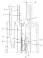
以下、本発明を具体化した実施例1を図1〜図8を参照して説明する。本実施例1のコネクタは、合成樹脂製のハウジング10と、ハウジング10に対し後方から挿入されて取り付けられる端子金具30とを備えて構成されている。尚、以下の説明において、前後の方向は、図2,4,6〜8における左側を前側と定義する。上下の方向については、図1〜7に表れる向きを基準とする。左右の方向については、図1,3,5に表れる向きを基準とする。
<Example 1>
A first embodiment of the present invention will be described below with reference to FIGS. The connector according to the first embodiment includes a
ハウジング10内には、前後方向に細長い端子収容室11が形成されている。端子収容室11には、ハウジング10の後方から端子金具30が挿入されるようになっている。ハウジング10には、端子収容室11の下面壁(内壁)に沿って前方へ片持ち状に延出した形態のランス12が、一体に形成されている。ランス12は、その後端部(基端部)を支点として上下方向(端子収容室11に対する端子金具30の挿入方向とほぼ直角に交差する方向)へ弾性撓みし得るようになっている。尚、以下のランス12の形状、位置関係等に関しては、ランス12が弾性撓みしていない自由状態を基準として説明する。
A
ランス12の上面、即ち端子収容室11に挿入された端子金具30と上下方向に対向する対向面13は、ランス12の前端から前後方向略中央位置に至る水平面14と、水平面14の後端からランス12の後端(基端)に至る傾斜面15とで構成されている。水平面14は、端子収容室11に対する端子金具30の挿入方向(以下、単に「挿入方向」という)と平行である。傾斜面15は、後方に向かって次第に端子金具30から離間するように下り勾配となるように傾斜している。
The upper surface of the
ランス12の前端面(延出端面)は、端子金具30の挿入方向と略直角に交差し、後述する端子金具30の係止部36に対し前後方向に対向、又は当接する受圧面16となっている。図3,4に示すように、受圧面16は、ランス12の水平面14の前端縁に直角に連なる第1鉛直面17と、第1鉛直面17の下端縁から下方へ連なるオーバーハング状の誘導面18と、第1鉛直面17と平行であって誘導面18の下端縁から下方へ連なる第2鉛直面19とから構成されている。第1鉛直面17と誘導面18と第2鉛直面19は、ランス12の弾性撓み方向に沿って上下に並んでいる。端子金具30が適正に端子収容室11に挿入された状態では、端子金具30の係止部36は、受圧面16のうち誘導面18に当接又は対向するようになっている。
The front end surface (extended end surface) of the
図4に示すように、誘導面18は、斜め下前方に面している。したがって、誘導面18に対して前方から押圧力が付与されると、誘導面18の傾斜により、ランス12には、上方、即ち端子金具30に接近する方向へ弾性撓みさせる力が作用するようになっている。また、上下方向において、誘導面18の形成領域は、傾斜面15の形成領域の範囲内となっている。つまり、誘導面18の最上端は、傾斜面15の最上端よりも少し低い高さに位置し、誘導面18の最下端は、傾斜面15の最下端と同じ高さに位置する。
As shown in FIG. 4, the
したがって、誘導面18から水平に後方(つまり、端子金具30が端子収容室11から抜き取られる方向)へ延ばした仮想水平面は、その高さが誘導面18の形成範囲内であれば、必ず、傾斜面15に到達する。誘導面18に対し前方から押圧力が作用すると、ランス12には、押圧力を受けた高さの仮想水平面に沿って剪断力が生じる。本実施例1では、この仮想水平面に沿ってランス12を仮想的に切断したときの断面を「剪断面」と定義し、この水平な剪断面の断面積を「剪断面積」と定義する。
Therefore, the virtual horizontal surface extending horizontally from the guide surface 18 (that is, the direction in which the terminal fitting 30 is extracted from the terminal accommodating chamber 11) is always inclined if the height is within the formation range of the
剪断面積は、剪断面(仮想水平面)の高さが誘導面18の上端に近いほど小さく、先端面の高さが誘導面18の下端に近いほど大きくなる。誘導面18に押圧力が作用した時のランス12の破壊強度は、剪断面積が大きいほど高くなる。ランス12の破壊強度が高いということは、端子金具30を抜止め状態に保持するためのランス12の保持力が強いことを意味する。
The shear area is smaller as the height of the shear plane (virtual horizontal plane) is closer to the upper end of the
図3に示すように、ランス12には、対向面13から段差状に下方へ凹んだ形態の左右対称な一対の切欠部20が形成されいる。切欠部20は、ランス12の前端面(受圧面16)及び左右両外側面に開放されている。切欠部20の側面は、端子金具30の挿入方向(前後方向)及びランス12の弾性撓み方向(上下方向)の両方向に対して直角な平坦面である。図4に示すように、切欠部20の底面は、前方に向かって下り勾配となった当接面21となっている。当接面21は、上方、即ち端子金具30と対向する方向に面している。また、切欠部20の後面は、前方に面するストッパ22となっている。
As shown in FIG. 3, the
前後方向における切欠部20(当接面21)の形成領域は、傾斜面15よりも前方の領域である。つまり、切欠部20と当接面21は、ランス12の前端から、水平面14の後端より前方の位置に至る範囲に亘って形成されている。また、上下方向における切欠部20(ストッパ22)の形成領域は、第1鉛直面17の全体、及び誘導面18における上端側の領域と対応している。つまり、切欠部20とストッパ22は、ランス12の上端(水平面14)から、誘導面18の下端よりも少し上方の位置に至る範囲に亘って形成されている。
The formation region of the notch 20 (contact surface 21) in the front-rear direction is a region in front of the
端子金具30は、所定形状の金属板材に曲げ加工等を施すことにより、全体として前後方向の細長い形状に成形したものである。端子金具30は、ハウジング10の後方から端子収容室11内に挿入され、ランス12の係止作用により後方への抜けが規制された状態に保持されている。図2に示すように、端子金具30の後端部には、オープンバレル状の圧着部31が形成され、この圧着部31には、電線32の前端部が接続されている。
The
端子金具30の前端部には、角筒部33が形成されている。図4,8に示すように、角筒部33を構成する底壁部34には、係止孔35が形成されている。端子金具30が端子収容室11に正規挿入された状態において、係止孔35はランス12と対応するように位置する。また、底壁部34には、係止孔35の開口縁における前端縁に沿うように係止部36が形成されている。係止部36は、底壁部34のうち係止孔35よりも前方の略台形状の領域を下方へ叩き出した形態である。係止部36の水平な後縁部は、ランス12に当接される押圧縁部37となっている。この押圧縁部37は、底壁部34よりも下方(つまり、ランス12側)に位置している。左右方向において、係止部36と押圧縁部37は、角筒部33(底壁部34)の中央に位置している。
A
図8に示すように、底壁部34には、左右対称な一対の撓み規制部38が形成されている。撓み規制部38は、係止孔35の開口縁のうち左右両側縁部から内側へ略方形状に張り出した形態である。撓み規制部38は、底壁部34に対して面一状に連なっている。したがって、図4に示すように、押圧縁部37は、撓み規制部38よりも下方に位置している。前後方向において、撓み規制部38は、押圧縁部37よりも少し後方に配置されている。また、図8に示すように、左右方向において、一対の撓み規制部38は、押圧縁部37の左右両端よりも更に外側方の位置に配置されている。
As shown in FIG. 8, the
次に、本実施例1の作用を説明する。端子収容室11に端子金具30を挿入する前の状態では、ランス12は、ランス12自体の剛性により弾性撓みしない自由状態を保つ。端子金具30を挿入する過程では、角筒部33の底壁部34の前端又は係止部36が、ランス12の傾斜面15に当接するので、ランス12は下方へ弾性撓みする。この状態から更に端子金具30の挿入が進む過程では、底壁部34又は係止部36が傾斜面15と水平面14に摺接する。
Next, the operation of the first embodiment will be described. In a state before the
そして、端子金具30が正規の挿入位置に到達すると、係止部36の押圧縁部37がランス12の前端を通過するので、ランス12は、その弾性復元力により上方へ弾性復帰して自由状態となる。この状態では、図4に示すように、ランス12の水平面14が押圧縁部37よりも上方に位置し、押圧縁部37が、誘導面18の上端部に対し前後方向に僅かな隙間を空けて対向する。
When the terminal fitting 30 reaches the proper insertion position, the
また、ランス12が自由状態に弾性復帰すると、ランス12の上端部が係止孔35内に進出し、ランス12のうち左右両切欠部20の間の部分が、左右一対の撓み規制部38の間で非接触状態で挟まれるように位置する。このとき、撓み規制部38と当接面21は非接触である。つまり、撓み規制部38の下面は、当接面21に対し所定の空間を空けて上下に対向するように位置する。また、撓み規制部38の後端は、ランス12のストッパ22に対し、僅かな隙間を空けて前後方向に対向した状態(つまり、非接触の状態)となる。
Further, when the
この状態から、端子金具30に後方への引張力が作用すると、端子金具30が僅かに後方へ変位したところで、押圧縁部37が誘導面18の上端部に当接し、ランス12が、殆ど弾性撓みせずに端子金具30に対して後方から係止した状態となる。このランス12の係止作用により、端子金具30は抜止め状態に保持される。この時、誘導面18における押圧縁部37との当接位置から後方へ延長した剪断面の剪断面積は、比較的小さいが、端子金具30に作用する引張力が小さければ、端子金具30は抜止め状態に保持される。
From this state, when a rearward tensile force is applied to the terminal fitting 30, when the terminal fitting 30 is slightly displaced rearward, the
しかし、端子金具30に作用する引張力が強い場合には、押圧縁部37から誘導面18に作用する前方からの押圧力も強くなるので、誘導面18の傾斜により、ランス12が上方(つまり、端子金具30に接近する方向)へ弾性撓みさせられる。そして、図6に示すように、当接面21が撓み規制部38に対して下から当接したところで、ランス12の上方変位が阻止される。この状態では、誘導面18における押圧縁部37の当接位置が、下方へ変位している。このとき、誘導面18の下端部から後方(端子金具30に対する引張り方向と平行な方向)に延長した剪断面Sa(図6参照)の剪断面積は、誘導面18の上端部における剪断面Sb(図4参照)の剪断面積よりも大きいので、ランス12の剪断強度、即ち端子金具30を抜止め状態に保持するための保持力が高まっている。
However, when the tensile force acting on the terminal fitting 30 is strong, the pressing force from the front acting on the
このようにランス12が上方へ弾性撓みした状態でも、ランス12の前端面である誘導面18は、斜め下前方を向いている。そのため、端子金具30に対する引張力が更に強くなった場合には、押圧縁部37からの押圧力により、ランス12がその上面(端子金具30との対向面13)を上方(端子金具30側)へ膨らませるように座屈変形することが懸念される。しかし、本実施例1では、誘導面18よりも後方(ランス12の基端側)の位置に当接面21を配置し、この当接面21に対して端子金具30の撓み規制部38が上から当接しているので、ランス12は上方へ膨らむような座屈変形を興じることはない。
Thus, even in a state where the
このように本実施例1では、ランス12が座屈変形しないようにしているので、端子金具30に対する引張力が強くなったときには、図7に示すように、端子金具30が後方へ僅かに変位しながら、押圧縁部37が誘導面18に食い込んでいく。そして、撓み規制部38の後端が、ランス12のストッパ22に対して前方から当接する。すると、ストッパ22に対する撓み規制部38の当接により、それ以上の端子金具30の後方変位と、誘導面18に対する押圧縁部37の食い込みが規制される。
Thus, in the first embodiment, since the
上述のように、本実施例1のコネクタは、ランス12の前端面に受圧面16が形成され、端子金具30に、受圧面16に対して前方から係止することで端子金具30を抜止めする係止部36が形成され、受圧面16に、係止部36が受圧面16を押圧したときにランス12を端子金具30に接近する方向へ撓ませる誘導面18が形成されている。また、ランス12における端子金具30との対向面13には、後方に向かって端子金具30から離間するように傾斜した傾斜面15が形成され、ランス12における受圧面16よりも後方の位置には、端子金具30側に面する当接面21が形成されいる。一方、端子金具30には、係止部36よりも後方の位置に、ランス12が弾性撓みしていない自由状態にあるときに、当接面21に対しランス12の弾性撓み方向と略平行な上下方向に間隔を空けて対向する撓み規制部38が形成されている。
As described above, in the connector of the first embodiment, the
この構成によれば、ランス12の前端面(受圧面16)に対し前方から係止部36の押圧力が作用したときに、ランス12が、その基端(後端)と延出端(前端)との間で上方へ座屈変形しようとしても、撓み規制部38と当接面21との当接によってランス12の座屈が防止される。したがって、本実施例1によれば、ランス12の座屈変形に起因してランス12による保持力が失われる虞がないので、ランス12による端子金具30の保持機能の信頼性に優れている。
According to this configuration, when the pressing force of the locking
また、係止部36の押圧縁部37が受圧面16の誘導面18に食い込んだときには、撓み規制部38がストッパ22に対して前方から当接することにより、ランス12に対する端子金具30の後方への相対変位を規制している。したがって、受圧面16に対する係止部36の過剰な食い込みが防止されている。
Further, when the
また、ランス12の弾性撓み方向(上下方向)における係止部36(押圧縁部37)と受圧面16(誘導面18)との係止代は、ランス12における端子金具30との対向面13から押圧縁部37までの距離に相当する。もし、ランス12における端子金具30との対向面13に当接面21を設定した場合、撓み規制部38と押圧縁部37との高低差が大きくなるので、端子金具30の形状が複雑化することになる。この点に鑑み、本実施例1では、ランス12に、端子金具30との対向面13に対して凹んだ形態の切欠部20を形成し、この切欠部20のうち端子金具30と対向する面を当接面21としている。これにより、撓み規制部38と係止部36との高低差が小さくなっているので、端子金具30の形状の簡素化が実現されている。
The locking margin between the locking portion 36 (pressing edge portion 37) and the pressure receiving surface 16 (guide surface 18) in the elastic deflection direction (vertical direction) of the
また、当接面21と撓み規制部38は、ランス12の弾性撓み方向(上下方向)及び端子金具30の挿入方向(前後方向)の両方向に対して交差する幅方向に関して、左右対称に一対ずつ設けられている。この構成によれば、当接面21が撓み規制部38に当接したときに、ランス12の姿勢が左右に傾くことがないので、ランス12による端子金具30の保持機能が安定する。
Further, the
また、撓み規制部38とストッパ22は、ランス12の弾性撓み方向及び端子金具30の挿入方向の両方向に対して交差する幅方向に関して、左右対称に一対ずつ設けられている。この構成によれば、撓み規制部38がストッパ22に当接したときに、ランス12の姿勢が左右に向きを変えることがないので、ランス12による端子金具30の保持機能が安定する。
Further, a pair of the
<他の実施例>
本発明は上記記述及び図面によって説明した実施例に限定されるものではなく、例えば次のような実施例も本発明の技術的範囲に含まれる。
(1)上記実施例1では、撓み規制部と当接面が、その後端部における狭い領域だけで上下に当接するようにしたが、撓み規制部と当接面は、前後方向に広い範囲に亘って面当たりするようにしてもよい。
(2)上記実施例1では、一対の当接面と一対の撓み規制部を左右対称な形態としたが、一対の当接面と一対の撓み規制部のうち少なくとも一方は、左右非対称な形態であってもよい。
(3)上記実施例1では、当接面と撓み規制部を一対ずつ設けたが、当接面と撓み規制部の数は、1つずつであってもよい。
(4)上記実施例1では、一対の撓み規制部と一対のストッパを左右対称な形態としたが、一対の撓み規制部と一対のストッパのうち少なくとも一方は、左右非対称な形態であってもよい。
(5)上記実施例1では、撓み規制部とストッパを一対ずつ設けたが、撓み規制部とストッパの数は、1つずつであってもよい。
(6)上記実施例1では、ランスにおける端子金具との対向面(ランスの弾性撓み方向において、係止部と受圧面の係止代の基準となる面)を凹ませた形態の切欠部を形成し、この切欠部内に当接面を設けたが、当接面は、ランスにおける端子金具との対向面に切欠部を形成せず、ランスの弾性撓み方向において係止部と受圧面の係止代の基準となる対向面に、当接面を配置してもよい。
(7)上記実施例1では、ランスが弾性撓みしない自由状態であるときに、当接面が、端子金具の挿入方向に対し前方に向かって下り勾配となるように傾斜する向きとしたが、当接面は、ランスが自由状態であるときに、端子金具の挿入方向と平行な面であってもよい。
(8)上記実施例1では、誘導面をランスの受圧面のみに形成したが、誘導面は、端子金具の係止部(押圧縁部)のみに形成してもよく、受圧面と係止部の両方に形成してもよい。
<参考例>
(1)上記実施例1では、係止部が受圧面に食い込んだときに、ランスに対する端子金具の後方への相対変位を規制するストッパを設けたが、このようなストッパを設けない形態とすることも考えられる。
<Other embodiments>
The present invention is not limited to the embodiments described with reference to the above description and drawings. For example, the following embodiments are also included in the technical scope of the present invention.
(1) In the first embodiment, the bending restricting portion and the contact surface are in contact with each other vertically only in a narrow region at the rear end portion, but the bending restricting portion and the contact surface are in a wide range in the front-rear direction. You may make it hit a surface over.
(2) In the first embodiment, the pair of contact surfaces and the pair of bending restricting portions are symmetrically formed, but at least one of the pair of contact surfaces and the pair of bending restricting portions is an asymmetric shape. It may be.
(3) In Example 1 described above, a pair of contact surfaces and deflection regulating portions are provided, but the number of contact surfaces and deflection regulating portions may be one each.
(4) In the first embodiment, the pair of bending restricting portions and the pair of stoppers have a bilaterally symmetric form, but at least one of the pair of bending restricting portions and the pair of stoppers may have a bilaterally asymmetric form. Good.
(5) In the first embodiment, a pair of bending restriction portions and stoppers are provided, but the number of bending restriction portions and stoppers may be one by one.
(6) In the first embodiment, the notch portion in the form in which the surface facing the terminal fitting in the lance (the surface serving as a reference for the locking margin between the locking portion and the pressure receiving surface in the elastic deflection direction of the lance) is recessed. The contact surface is formed in the notch, but the contact surface does not form a notch on the surface of the lance facing the terminal fitting, and the engagement between the locking portion and the pressure receiving surface in the elastic deflection direction of the lance. You may arrange | position a contact surface in the opposing surface used as the reference | standard of a stop allowance.
(7) In Example 1 described above, when the lance is in a free state where it does not elastically bend, the contact surface is inclined so as to have a downward slope toward the front with respect to the insertion direction of the terminal fitting. The contact surface may be a surface parallel to the insertion direction of the terminal fitting when the lance is in a free state.
(8) In the first embodiment, the guide surface is formed only on the pressure-receiving surface of the lance. However, the guide surface may be formed only on the locking portion (pressing edge portion) of the terminal fitting. You may form in both parts.
<Reference example>
(1) In the first embodiment, a stopper is provided that restricts the relative displacement of the terminal fitting to the rear of the lance when the locking portion bites into the pressure receiving surface. However, such a stopper is not provided. It is also possible.
10…ハウジング
11…端子収容室
12…ランス
13…対向面
15…傾斜面
16…受圧面
18…誘導面
20…切欠部
21…当接面
22…ストッパ
30…端子金具
36…係止部
38…撓み規制部
DESCRIPTION OF
Claims (4)
後方から前記端子収容室に挿入される端子金具と、
前記端子収容室の内壁に沿って前方へ片持ち状に延出した形態であり、前記端子収容室に対する前記端子金具の挿入過程では挿入方向と交差する方向に弾性撓みし、前記端子金具が前記端子収容室に正規挿入されると自由状態に弾性復帰する合成樹脂製のランスと、
前記ランスの前端面に形成された受圧面と、
前記端子金具に形成され、前記受圧面に対して前方から係止することで前記端子金具を抜止めする係止部と、
前記ランスにおける前記端子金具との対向面に形成され、後方に向かって前記端子金具から離間するように傾斜した傾斜面と、
前記受圧面と前記係止部のうち少なくとも一方に形成され、前記係止部が前記受圧面を押圧したときに、前記ランスを前記端子金具に接近する方向へ撓ませる誘導面と、
前記ランスにおける前記受圧面よりも後方の位置に形成され、前記端子金具側に面する当接面と、
前記端子金具における前記係止部よりも後方の位置に形成され、前記ランスが弾性撓みしていない自由状態にあるときに、前記当接面に対し前記ランスの弾性撓み方向と略平行な方向に間隔を空けて対向する撓み規制部と、
前記ランスに形成され、前記係止部が前記受圧面に食い込んだときに、前記撓み規制部を前方から当接させることにより、前記ランスに対する前記端子金具の後方への相対変位を規制するストッパとを備えていることを特徴とするコネクタ。 A housing having a terminal accommodating chamber formed therein;
A terminal fitting inserted into the terminal accommodating chamber from behind,
It is a form that cantilevered forward along the inner wall of the terminal accommodating chamber, and in the process of inserting the terminal fitting into the terminal accommodating chamber, the terminal fitting is elastically bent in a direction intersecting the insertion direction, and the terminal fitting is A synthetic resin lance that elastically returns to a free state when it is properly inserted into the terminal accommodating chamber;
A pressure-receiving surface formed on the front end surface of the lance;
A locking portion formed on the terminal metal fitting, for retaining the terminal metal fitting by locking the pressure receiving surface from the front;
An inclined surface that is formed on a surface of the lance facing the terminal fitting and is inclined so as to be separated from the terminal fitting toward the rear;
A guide surface that is formed on at least one of the pressure receiving surface and the locking portion, and deflects the lance in a direction approaching the terminal fitting when the locking portion presses the pressure receiving surface;
A contact surface that is formed at a position behind the pressure-receiving surface of the lance and faces the terminal fitting;
When the lance is in a free state in which the lance is not elastically bent, the lance is formed in a direction substantially parallel to the elastic deflection direction of the lance with respect to the contact surface. A deflection restricting portion opposed to each other with an interval between;
A stopper that is formed on the lance and restricts the relative displacement of the terminal fitting to the rear with respect to the lance by bringing the bending restricting portion into contact with the lance when the engaging portion bites into the pressure receiving surface. A connector characterized by comprising:
Priority Applications (4)
| Application Number | Priority Date | Filing Date | Title |
|---|---|---|---|
| JP2013093994A JP6004278B2 (en) | 2013-04-26 | 2013-04-26 | connector |
| CN201380075782.9A CN105229864B (en) | 2013-04-26 | 2013-12-04 | Connector |
| US14/782,332 US9509077B2 (en) | 2013-04-26 | 2013-12-04 | Connector with locking lance and terminal fitting with deflection regulating portion for regulating deflection of the locking lance |
| PCT/JP2013/082633 WO2014174718A1 (en) | 2013-04-26 | 2013-12-04 | Connector |
Applications Claiming Priority (1)
| Application Number | Priority Date | Filing Date | Title |
|---|---|---|---|
| JP2013093994A JP6004278B2 (en) | 2013-04-26 | 2013-04-26 | connector |
Publications (3)
| Publication Number | Publication Date |
|---|---|
| JP2014216243A JP2014216243A (en) | 2014-11-17 |
| JP2014216243A5 JP2014216243A5 (en) | 2015-10-15 |
| JP6004278B2 true JP6004278B2 (en) | 2016-10-05 |
Family
ID=51791309
Family Applications (1)
| Application Number | Title | Priority Date | Filing Date |
|---|---|---|---|
| JP2013093994A Active JP6004278B2 (en) | 2013-04-26 | 2013-04-26 | connector |
Country Status (4)
| Country | Link |
|---|---|
| US (1) | US9509077B2 (en) |
| JP (1) | JP6004278B2 (en) |
| CN (1) | CN105229864B (en) |
| WO (1) | WO2014174718A1 (en) |
Families Citing this family (12)
| Publication number | Priority date | Publication date | Assignee | Title |
|---|---|---|---|---|
| JP6048342B2 (en) * | 2013-08-09 | 2016-12-21 | 住友電装株式会社 | connector |
| JP6064832B2 (en) * | 2013-08-09 | 2017-01-25 | 住友電装株式会社 | connector |
| JP2016207253A (en) * | 2015-04-15 | 2016-12-08 | 矢崎総業株式会社 | Connection structure for connector and terminal fitting |
| JP6380241B2 (en) * | 2015-06-09 | 2018-08-29 | 住友電装株式会社 | connector |
| CN106486809A (en) * | 2016-10-31 | 2017-03-08 | 河南天海电器有限公司 | A kind of new type of plug terminal |
| JP2018120687A (en) * | 2017-01-24 | 2018-08-02 | 住友電装株式会社 | connector |
| JP6865075B2 (en) * | 2017-03-16 | 2021-04-28 | 矢崎総業株式会社 | connector |
| JP6780571B2 (en) * | 2017-04-10 | 2020-11-04 | 住友電装株式会社 | Terminal bracket |
| KR102366167B1 (en) * | 2017-09-13 | 2022-02-22 | 한국단자공업 주식회사 | Connector |
| CN109546424B (en) * | 2017-09-22 | 2021-04-09 | 上海莫仕连接器有限公司 | Electric connector assembly and electric connector |
| JP2020102338A (en) * | 2018-12-21 | 2020-07-02 | タイコエレクトロニクスジャパン合同会社 | Connector housing and connector |
| JP7424247B2 (en) * | 2020-08-26 | 2024-01-30 | 住友電装株式会社 | connector |
Family Cites Families (8)
| Publication number | Priority date | Publication date | Assignee | Title |
|---|---|---|---|---|
| JP2003257532A (en) * | 2002-03-01 | 2003-09-12 | Sumitomo Wiring Syst Ltd | Connector |
| JP3912204B2 (en) | 2002-06-28 | 2007-05-09 | 住友電装株式会社 | connector |
| DE60223352T2 (en) * | 2002-07-04 | 2008-08-28 | Sumitomo Wiring Systems, Ltd., Yokkaichi | Interconnects |
| JP4457917B2 (en) * | 2005-02-23 | 2010-04-28 | 住友電装株式会社 | connector |
| EP1786066B1 (en) * | 2005-11-15 | 2011-01-26 | Sumitomo Wiring Systems, Ltd. | A connector |
| JP2007141509A (en) * | 2005-11-15 | 2007-06-07 | Sumitomo Wiring Syst Ltd | Terminal fitting |
| JP2009123373A (en) * | 2007-11-12 | 2009-06-04 | Sumitomo Wiring Syst Ltd | Connector |
| JP2012216344A (en) * | 2011-03-31 | 2012-11-08 | Sumitomo Wiring Syst Ltd | Connector |
-
2013
- 2013-04-26 JP JP2013093994A patent/JP6004278B2/en active Active
- 2013-12-04 WO PCT/JP2013/082633 patent/WO2014174718A1/en active Application Filing
- 2013-12-04 US US14/782,332 patent/US9509077B2/en active Active
- 2013-12-04 CN CN201380075782.9A patent/CN105229864B/en active Active
Also Published As
| Publication number | Publication date |
|---|---|
| US20160164212A1 (en) | 2016-06-09 |
| JP2014216243A (en) | 2014-11-17 |
| CN105229864B (en) | 2017-09-22 |
| US9509077B2 (en) | 2016-11-29 |
| WO2014174718A1 (en) | 2014-10-30 |
| CN105229864A (en) | 2016-01-06 |
Similar Documents
| Publication | Publication Date | Title |
|---|---|---|
| JP6004278B2 (en) | connector | |
| JP5831818B2 (en) | connector | |
| JP2009123373A (en) | Connector | |
| JP5810980B2 (en) | connector | |
| JP5454121B2 (en) | connector | |
| JP5737216B2 (en) | connector | |
| JP5757426B2 (en) | connector | |
| JP2013187117A (en) | Connector | |
| JP2014099332A (en) | Connector | |
| JP2011249169A (en) | Terminal fitting | |
| JP5999510B2 (en) | Female terminal fitting and manufacturing method thereof | |
| JP2011216435A (en) | Terminal fitting | |
| JP5482557B2 (en) | Terminal fittings and connectors | |
| JP5569267B2 (en) | connector | |
| WO2012029351A1 (en) | Connector | |
| WO2019035331A1 (en) | Connector | |
| JP2011253717A (en) | Connector | |
| JP4304478B2 (en) | connector | |
| JP2020080271A (en) | connector | |
| JP2005216810A (en) | Connector | |
| JP4220937B2 (en) | connector | |
| JP5505288B2 (en) | Terminal fitting | |
| JP2010003465A (en) | Female connector | |
| JP6597434B2 (en) | connector | |
| JP6327521B2 (en) | connector |
Legal Events
| Date | Code | Title | Description |
|---|---|---|---|
| A621 | Written request for application examination |
Free format text: JAPANESE INTERMEDIATE CODE: A621 Effective date: 20150630 |
|
| A521 | Written amendment |
Free format text: JAPANESE INTERMEDIATE CODE: A523 Effective date: 20150827 |
|
| A131 | Notification of reasons for refusal |
Free format text: JAPANESE INTERMEDIATE CODE: A131 Effective date: 20160603 |
|
| A521 | Written amendment |
Free format text: JAPANESE INTERMEDIATE CODE: A523 Effective date: 20160722 |
|
| TRDD | Decision of grant or rejection written | ||
| A01 | Written decision to grant a patent or to grant a registration (utility model) |
Free format text: JAPANESE INTERMEDIATE CODE: A01 Effective date: 20160812 |
|
| A61 | First payment of annual fees (during grant procedure) |
Free format text: JAPANESE INTERMEDIATE CODE: A61 Effective date: 20160825 |
|
| R150 | Certificate of patent (=grant) or registration of utility model |
Ref document number: 6004278 Country of ref document: JP Free format text: JAPANESE INTERMEDIATE CODE: R150 |