WO2019035331A1 - Connector - Google Patents
Connector Download PDFInfo
- Publication number
- WO2019035331A1 WO2019035331A1 PCT/JP2018/028015 JP2018028015W WO2019035331A1 WO 2019035331 A1 WO2019035331 A1 WO 2019035331A1 JP 2018028015 W JP2018028015 W JP 2018028015W WO 2019035331 A1 WO2019035331 A1 WO 2019035331A1
- Authority
- WO
- WIPO (PCT)
- Prior art keywords
- lance
- housing
- terminal module
- connector
- insertion space
- Prior art date
Links
Images


Classifications
-
- H—ELECTRICITY
- H01—ELECTRIC ELEMENTS
- H01R—ELECTRICALLY-CONDUCTIVE CONNECTIONS; STRUCTURAL ASSOCIATIONS OF A PLURALITY OF MUTUALLY-INSULATED ELECTRICAL CONNECTING ELEMENTS; COUPLING DEVICES; CURRENT COLLECTORS
- H01R13/00—Details of coupling devices of the kinds covered by groups H01R12/70 or H01R24/00 - H01R33/00
- H01R13/40—Securing contact members in or to a base or case; Insulating of contact members
- H01R13/42—Securing in a demountable manner
- H01R13/422—Securing in resilient one-piece base or case, e.g. by friction; One-piece base or case formed with resilient locking means
- H01R13/4223—Securing in resilient one-piece base or case, e.g. by friction; One-piece base or case formed with resilient locking means comprising integral flexible contact retaining fingers
-
- H—ELECTRICITY
- H01—ELECTRIC ELEMENTS
- H01R—ELECTRICALLY-CONDUCTIVE CONNECTIONS; STRUCTURAL ASSOCIATIONS OF A PLURALITY OF MUTUALLY-INSULATED ELECTRICAL CONNECTING ELEMENTS; COUPLING DEVICES; CURRENT COLLECTORS
- H01R13/00—Details of coupling devices of the kinds covered by groups H01R12/70 or H01R24/00 - H01R33/00
- H01R13/64—Means for preventing incorrect coupling
- H01R13/641—Means for preventing incorrect coupling by indicating incorrect coupling; by indicating correct or full engagement
-
- H—ELECTRICITY
- H01—ELECTRIC ELEMENTS
- H01R—ELECTRICALLY-CONDUCTIVE CONNECTIONS; STRUCTURAL ASSOCIATIONS OF A PLURALITY OF MUTUALLY-INSULATED ELECTRICAL CONNECTING ELEMENTS; COUPLING DEVICES; CURRENT COLLECTORS
- H01R13/00—Details of coupling devices of the kinds covered by groups H01R12/70 or H01R24/00 - H01R33/00
- H01R13/648—Protective earth or shield arrangements on coupling devices, e.g. anti-static shielding
- H01R13/658—High frequency shielding arrangements, e.g. against EMI [Electro-Magnetic Interference] or EMP [Electro-Magnetic Pulse]
- H01R13/6591—Specific features or arrangements of connection of shield to conductive members
- H01R13/6592—Specific features or arrangements of connection of shield to conductive members the conductive member being a shielded cable
Definitions
- the present invention relates to a connector.
- Patent Document 1 discloses a connector for inserting a contact into a contact receiving cavity formed in a housing, and locking a lance formed in the contact receiving cavity to the contact to prevent the contact from being removed.
- the lance elastically deforms due to the interference with the contact, and when the contact is in the normal insertion state, the lance elastically returns and locks on the contact.
- the lance is housed inside the housing.
- the lance may be pushed into the contact receiving cavity and plastically deformed when foreign matter hits the outer surface of the lance.
- the present invention has been completed based on the above circumstances, and it is an object of the present invention to prevent unauthorized deformation of a lance.
- the connector of the present invention is A housing having an insertion space; An insertion member insertable into the insertion space; The outer surface is formed on the housing so as to be exposed to the outside of the housing, and in the process of inserting the insertion member into the insertion space, it is elastically deformed to the outer surface side, and elastically returns when the insertion member is properly inserted.
- a lance for retaining the insertion member; The lance is characterized in that the lance is formed with the lance, and the lance is restricted to be displaced to the insertion space side by being locked to the housing.
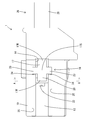
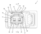
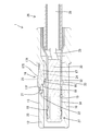
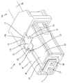
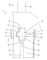
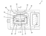
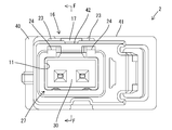
- the perspective view of the connector in the state where the terminal module was properly inserted into the housing in the first embodiment Top view of the connector with the terminal module properly inserted into the housing AA line sectional view of FIG. 2 BB line sectional view of FIG. 3
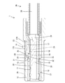
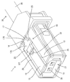
- the perspective view of the connector in the state where the terminal module was properly inserted into the housing in the second embodiment Top view of the connector with the terminal module properly inserted into the housing DD line cross section of FIG. 9 EE line sectional view of FIG. 10
- the present invention is configured such that the lance extends in a cantilever shape substantially in parallel with the insertion direction of the insertion member, and the restricting portion extends beyond the proximal end in the extension direction of the lance. It may be arranged at the position of.
- the lance elastically deforms to the outer surface due to the interference with the insertion member, the amount of deflection of the lance becomes maximum at the proximal end, so if the restriction portion is formed at the proximal end of the lance, the proximal end of the lance The bending rigidity is increased, and the resistance when inserting the insertion member is increased.
- the restriction portion is formed at a position closer to the extending end than the proximal end in the extending direction of the lance.
- the outer surface of the lance may be disposed at a position deeper than the outer wall surface of the housing when the lance is in a free state in which it does not elastically deform. According to this configuration, the foreign matter is less likely to interfere with the outer surface of the lance.
- the lance may be cantilevered substantially parallel to the insertion direction of the insertion member, and a pair of the restriction portions may project from both side edges of the lance. According to this configuration, when the restricting portion abuts on the housing to restrict the elastic deformation of the lance, there is no possibility that the lance may tilt.
- a detection groove may be formed on the outer wall surface of the housing so as to face the restriction portion displaced in accordance with the elastic deformation of the lance. According to this configuration, the lance elastically deforms to the outer surface side when the insertion member is partially inserted. In this state, when the mating member is fitted along the detection groove, the mating member abuts against the restricting portion, and this abutment can detect that the insertion member is in the partially inserted state.
- the lance extends in a cantilever shape substantially in parallel with the insertion direction of the insertion member, and the outer wall surface of the housing is a guide extending toward the extension end of the lance.
- a groove may be formed.
- Example 1 A first embodiment of the present invention will now be described with reference to FIGS. 1 to 7.
- the lower left in FIGS. 1 and 5 and the left in FIGS. 2, 4 and 7 are defined as the front.
- the directions appearing in FIGS. 1, 3, 5 to 7 are defined as upper and lower as they are.
- the connector 1 is configured to include a housing 10 made of synthetic resin and a terminal module 27 (an insertion member described in the claims) configuring the shield conductive path 26.
- the terminal module 27 is inserted into the housing 10 from the rear.
- the shield conductive path 26 is configured by attaching the terminal module 27 to the front end of the shield wire 28.
- the terminal module 27 includes an inner conductor (not shown) individually connected to the twisted pair wires 29 constituting the shielded wire 28, a dielectric 30 for housing the inner conductor, and an outer conductor 31 for surrounding the dielectric 30. It is configured.
- the terminal module 27 is provided with a locking projection 32 projecting from the upper surface of the outer conductor 31 and an abutting projection 33 projecting from the lower surface of the outer conductor 31.
- the housing 10 is generally in the form of a block, and an insertion space 11 is formed in the housing 10.
- the front end portion of the insertion space 11 opens at the front end surface of the housing 10, and the rear end portion of the insertion space 11 opens at the rear end surface of the housing 10 as an insertion port.
- the upper wall portion 12 which partitions the insertion space 11 constitutes an upper wall surface 13 (an outer wall surface described in the claims) of the housing 10.
- the upper wall portion 12 is formed with a notch portion 14 for communicating the outside of the housing 10 with the inside of the insertion space 11.
- the planar view shape (shape seen from the direction orthogonal to the upper wall surface 13) of the notch part 14 is a rectangle long in the front-back direction as a whole.
- the housing 10 is formed with a front stop 15 in a form projecting from the bottom of the insertion space 11.
- the housing 10 is integrally formed with a lance 16 which is cantilevered forward along the ceiling surface of the insertion space 11.
- the lance 16 is provided with a lance body 17 and a pair of left and right restricting portions 23.
- the plan view shape of the lance body 17 is rectangular like a notch 14 long in the front-rear direction.
- the lance main body portion 17 constitutes the upper wall portion 12 of the housing 10 by being accommodated in the notch portion 14.
- the rear end 17R of the lance main body 17 (the base end of the lance described in the claims) is continuous with the rear edge of the opening area of the notch 14, but the front end 17F of the lance main body 17 (claim The extended end of the lance described in the above and the left and right side edges are not in contact with the opening edge of the notch 14. That is, between the opening edge of the notch 14 and the outer peripheral edge of the lance body 17, there is a slit having a substantially U-shaped plan view. That is, the lance body 17 (lance 16) is cantilevered forward, and is elastically deformed upward (on the upper wall 13 side of the housing 10) with the rear end 17R of the lance body 17 as a fulcrum. It is supposed to be able to
- a retaining projection 18 is formed on the lower surface of the lance body 17. As shown in FIGS. 1 to 4, when the lance 16 is in the non-elastically deformed retaining position (free state), the retaining projection 18 advances into the insertion path of the terminal module 27 in the insertion space 11. As shown in FIGS. 5 to 7, when the lance 16 is at the release position elastically displaced upward, the retaining projection 18 retracts above the insertion space 11.
- the front end surface of the retaining projection 18 is a locking surface 19 and is located slightly behind the front end of the lance body 17. The rear end of the retaining projection 18 is located slightly forward of the rear end of the lance body 17.
- the entire area of the upper surface 17S of the lance body 17 (the outer surface of the lance described in the claims) is slightly lower than the upper wall 13 of the housing 10 (relative to the upper wall 13). In the recessed position).
- the region of the top surface 17S of the lance body 17 on the front end 17F side is displaced to a position higher than the top wall 13 of the housing 10 (a position protruding from the top wall 13).
- a front end (extension end) of the upper surface 17S of the lance main body 17 is a guiding slope 20.
- the formation area of the guiding slope 20 in the front-rear direction is a range from the front end of the lance body 17 to a position slightly behind the locking surface 19.
- the guiding slope 20 slopes downward toward the front.
- the lower surface (inner surface) of the front end portion of the lance body 17 is a jig receiving surface 21.
- the formation area of the jig receiving surface 21 in the front-rear direction is a range extending from the front end of the lance body 17 to a position forward of the locking surface 19.
- the jig receiving surface 21 is inclined so as to be inclined upward toward the front.
- the housing 10 is formed with a jig insertion portion 22 in which a part (central portion in the left-right direction) of the front edge portion of the cutout portion 14 in a plan view is recessed.
- the jig receiving surface 21 is positioned to approach and oppose the jig insertion portion 22 in the front-rear direction.
- the lance 16 is integrally formed with a pair of left and right restricting portions 23 which are square in plan view.
- the restricting portion 23 protrudes outward in the left-right direction (width direction) from the left and right side edge portions of the lance main body portion 17.
- the formation area of the restricting portion 23 in the front-rear direction is a position (retracting stop) in front of the rear end of the lance body 17 from a position slightly behind the locking surface 19 (a position slightly behind the rear end of the guiding slope 20). (A position slightly ahead of the rear end of the projection 18).
- the formation region of the restriction portion 23 is only a part of the side edge along the extension direction of the lance 16, and the restriction portion 23 is a base end portion (rear end portion 17R in the extension direction of the lance 16). ) Is disposed at a position closer to the extension end (on the front end 17F side).
- the thickness dimension (the dimension in the direction substantially parallel to the elastic deformation direction of the lance 16) of the restricting portion 23 is smaller than the maximum thickness dimension of the lance body 17.
- the upper surface of the restriction portion 23 is flush with the region of the upper surface 17S of the lance 16 behind the guiding slope 20.
- the lower surface of the restricting portion 23 is located above the lower surface of the lance body 17.
- the restricting portion 23 protrudes laterally from the left and right side edges of the lance main body portion 17, and therefore protrudes outward of the opening region of the cutout portion 14 in a plan view.
- a pair of laterally symmetrical stoppers 24 are formed on the housing 10 by recessing the left and right side edge portions of the opening region of the notch portion 14 of the upper wall surface 13 of the housing 10 so as to correspond to the regulation portion 23. ing.
- the stopper 24 faces upward and is positioned to vertically face the lower surface (inner surface) of the regulating portion 23.
- the lower surface of the restricting portion 23 is positioned to face the stopper 24 with a slight gap.
- the restricting portion 23 is displaced upward away from the stopper 24.
- the regulating portion 23 abuts against the stopper 24 when the lance 16 is displaced slightly downward, The elastic deformation of the is to be regulated.
- a pair of left and right detection grooves 25 are formed on the upper wall surface 13 of the housing 10.
- the pair of detection grooves 25 linearly extend in the front-rear direction from the front end of the upper wall surface 13 of the housing 10 toward the left and right restricting portions 23. That is, the pair of detection grooves 25 are positioned to correspond to the pair of restricting portions 23 in the left-right direction.
- the rear end of the detection groove 25 is in communication with the notch 14.
- the groove lower surface of the detection groove 25 has substantially the same height as the upper surface of the restricting portion 23 when the lance 16 is in the retaining position. Therefore, when the lance 16 is elastically deformed to the release position, the restricting portion 23 is displaced to a position higher than the bottom of the detection groove 25.
- the terminal module 27 When assembling the terminal module 27 and the housing 10, the terminal module 27 is inserted into the insertion space 11 from the rear of the housing 10. In the process of insertion, when the terminal module 27 reaches the half insertion position just before the regular insertion position, the locking projection 32 of the outer conductor 31 abuts on the retaining projection 18 of the lance 16, as shown in FIG. The lance 16 is elastically deformed from the retaining position to the release position. From this state, when the insertion proceeds and the terminal module 27 reaches the normal insertion position, the abutment projection 33 of the terminal module 27 abuts on the front stop 15 of the insertion space 11, so further insertion of the terminal module 27 takes place. It is regulated.
- the locking projection 32 passes through the locking projection 18 so that the lance 16 in the release position elastically returns to the locking position and the locking surface 19 of the locking projection 18 is locked.
- the projection 32 is locked from behind.
- the terminal module 27 is restricted in its rearward displacement and held at the normal insertion position.
- the retaining projection 18 abuts on the upper surface of the outer conductor 31, and the lower surface of the front end portion of the lance main body 17 abuts on the upper surface of the locking projection 32. Does not improperly move in the opposite direction (downward).
- the connector 1 is fitted to a mating connector (for example, the substrate connector 1) not shown.
- a mating connector for example, the substrate connector 1
- detection ribs individually formed in the pair of detection grooves 25 in the fitting process are formed. Therefore, the incorrect orientation in which the connector 1 is upside down with respect to the mating connector There is no risk of being fitted with
- the fitting direction leading end of the detection rib is positioned so as to cover the upper surface of the regulating portion 23.
- the locking projection 32 remains in interference with the retaining projection 18 so that the lance 16 is lifted to the release position It becomes a state.
- the detection rib abuts on the front end of the restricting portion 23, so the connector 1 and the mating connector can not be fitted properly. By this, it can be detected that the terminal module 27 remains in the partially inserted state.
- the same configuration as the detection rib may be provided in the continuity inspection device (not shown).
- the connector 1 is set in the conduction detection device, it is possible to detect the presence of the terminal module 27 in the semi-inserted state.
- a jig (not shown) is inserted into the jig insertion portion 22 and abuts on the jig receiving surface 21 of the lance 16, and the jig is inclined to make the lever
- the lance 16 is elastically deformed to the release position.
- the retaining projection 18 separates from the locking projection 32 and retracts above the locking projection 32, so that the terminal module 27 is released from the retention state.
- the twist pair wire 29 may be pinched to pull the terminal module 27 backward.
- the connector 1 of the first embodiment includes a housing 10 having an insertion space 11, a terminal module 27 which can be inserted into the insertion space 11, and a lance 16.
- the lance 16 is formed in the housing 10 so that the upper surface 17S (outer surface) is exposed to the outside of the housing 10.
- the lance 16 elastically deforms to the outer surface (upper surface 17S) side, and when the terminal module 27 is properly inserted, the lance 16 elastically returns to prevent the terminal module 27 from being removed. It is supposed to
- the lance 16 In the state in which the terminal module 27 is inserted into the insertion space 11, the lance 16 abuts on the upper surface of the outer conductor 31 and therefore does not displace downward (in the direction of advancing into the insertion space 11). However, before the terminal module 27 is inserted into the housing 10, there is no member for supporting the lance 16 from the insertion space 11 side. Moreover, the outer surface (upper surface 17S) of the lance 16 is exposed to the outside of the housing 10. Therefore, when the outer surface (upper surface 17S) of the lance 16 is pressed, there is a concern that the lance 16 may be deformed illegally to advance into the insertion space 11.
- a regulating portion 23 is formed in the lance 16.
- the lance 16 is cantilevered in a direction (forward) substantially parallel to the insertion direction of the terminal module 27.
- the amount of deflection of the lance 16 is maximum at the rear end 17R (proximal end). Therefore, when the restricting portion 23 is formed at the rear end 17R of the lance 16, the bending rigidity of the rear end 17R of the lance 16 becomes high, and the resistance when inserting the terminal module 27 becomes large.
- the restricting portion 23 is disposed at a position closer to the front end 17F than the rear end 17R in the extension direction of the lance 16.
- the portion of the lance 16 on the side of the front end 17F where the restricting portion 23 is formed has a smaller amount of deflection than the rear end 17R of the lance 16. Therefore, even if the restricting portion 23 is formed in the lance 16, the bending rigidity does not increase when the lance 16 elastically deforms, and the resistance when inserting the terminal module 27 does not increase.
- the outer surface of the lance 16 (the upper surface 17S of the lance main body 17) is at a position deeper than the upper wall surface 13 of the housing 10. Because they are disposed, foreign matter is less likely to interfere with the outer surface (upper surface 17S) of the lance 16.
- the lance 16 is cantilevered substantially parallel to the insertion direction of the terminal module 27. Focusing on this form, the pair of restricting portions 23 are protruded from the left and right side edge portions of the lance 16. According to this configuration, when the pair of left and right restricting portions 23 abut on the housing 10 to restrict the elastic deformation of the lance 16, the lance 16 can be prevented from tilting.
- a detection groove 25 is formed on the upper wall surface 13 of the housing 10 so as to face the restricting portion 23 displaced in accordance with the elastic deformation of the lance 16.
- the lance 16 elastically deforms to the upper surface 17S (outer surface) side, but in this state, along the detection groove 25, the other member (detection rib of the other connector, etc.)
- the counterpart member abuts against the restricting portion 23. Thereby, it can be detected that the terminal module 27 remains in the half inserted state.
- Example 2 Next, a second embodiment of the present invention will be described with reference to FIGS.
- the connector 2 of the second embodiment is configured such that the shape of the upper wall surface 41 (the outer wall surface described in the claims) of the housing 40 is different from that of the first embodiment.
- the other parts of the configuration are the same as those of the first embodiment, and thus the same reference numerals are given to the same components, and descriptions of the structures, operations, and effects are omitted.
- the upper wall 13 of the housing 10 is formed with the pair of detection grooves 25 corresponding to the pair of restricting portions in the left-right direction.
- the detection groove 25 is not formed on the wall surface 41, and only one guide groove 42 is formed.
- the guide groove 42 is arranged not to correspond to the pair of restricting portions 23 and to correspond to the lance main body portion 17.
- the rear end of the guide groove 42 faces the jig insertion portion 22. That is, the guide groove 42 and the jig insertion portion 22 communicate with each other.
- the guide groove 42 is formed focusing on the point that the lance 16 is cantilevered substantially parallel (forward) to the insertion direction of the terminal module 27.
- the guide groove 42 extends linearly from the front end edge of the housing 10 toward the front end 17F (extension end) of the lance 16 in which the jig receiving surface 21 is formed. Therefore, when disengaging the lance 16 from the terminal module 27, sliding the jig (not shown) backward along the guide groove 42 ensures that the jig is guided to the jig insertion portion 22, Dive into jig receiving surface 21 (inside of front end 17F of lance 16). Therefore, the workability is excellent.
- the present invention is not limited to the embodiments described above with reference to the drawings.
- the following embodiments are also included in the technical scope of the present invention.
- the restricting portion is disposed at a position closer to the extending end than the proximal end in the extending direction of the lance, the restricting portion may be disposed at the proximal end of the lance.
- the restricting portion is disposed only at a part of the side edge along the extending direction of the lance, but the restricting portion continues over the entire length of the side edge of the lance. It may be formed as follows.
- the outer surface of the lance when the lance is in the free state, the outer surface of the lance is disposed at a position recessed from the outer wall surface of the housing, but the outer surface of the lance is flush with the outer surface wall of the housing. Or may project beyond the outer wall of the housing.
- the restricting portion protrudes from the side edge of the lance, but the restricting portion may protrude forward from the extending end of the lance.
- the insertion member is a terminal module in which the dielectric in which the inner conductor is accommodated is surrounded by the outer conductor
- the insertion member is the inner conductor
- the present invention can also be applied to the case where a lance is formed in the dielectric, or the case where the insertion member is an exposed terminal fitting not accommodated in the dielectric or the like.
Abstract
The present invention prevents a lance from being improperly deformed. This connector (1) is provided with: a housing (10) having an insertion space (11); a terminal module (27) which can be inserted into the insertion space (11); a lance (16) having an outer surface (17S) that is disposed in the housing (10) so as to be exposed to the outside of the housing (10), the lance (16) elastically deforming toward the outer surface (17S) during the course of inserting the terminal module (27) into the insertion space (11), and elastically recovering after the terminal module (27) is inserted normally, thereby fixing the terminal module (27) so that the terminal module (27) does not fall out; and a restricting part (23) formed in the lance (16) and locked to the housing (10) to restrict the displacement of the lance (16) toward the insertion space (11).
Description
本発明は、コネクタに関するものである。
The present invention relates to a connector.
特許文献1には、ハウジングに形成したコンタクト収容キャビティ内に、コンタクトを挿入し、コンタクト収容キャビティに形成したランスをコンタクトに係止させることで、コンタクトを抜止めするコネクタが開示されている。コンタクトの挿入過程では、ランスがコンタクトとの干渉によって弾性変形し、コンタクトが正規挿入状態になるとランスが弾性復帰にしてコンタクトに係止する。
Patent Document 1 discloses a connector for inserting a contact into a contact receiving cavity formed in a housing, and locking a lance formed in the contact receiving cavity to the contact to prevent the contact from being removed. In the process of inserting the contact, the lance elastically deforms due to the interference with the contact, and when the contact is in the normal insertion state, the lance elastically returns and locks on the contact.
上記コネクタでは、ランスがハウジングの内部に収容された形態となっている。このコネクタにおいて低背化を図ろうとする場合、ハウジングのうちランスを覆っている部分を除去し、ランスがハウジングの外面に露出した状態とする構造が考えられる。しかし、ランスをハウジングの外面に露出させてしまうと、異物がランスの外面に当たったときに、ランスがコンタクト収容キャビティ内に押し込まれ、塑性変形してしまうことが懸念される。
In the above connector, the lance is housed inside the housing. In order to reduce the height of the connector, it is conceivable to remove the portion of the housing covering the lance and leave the lance exposed on the outer surface of the housing. However, if the lance is exposed to the outer surface of the housing, there is a concern that the lance may be pushed into the contact receiving cavity and plastically deformed when foreign matter hits the outer surface of the lance.
本発明は上記のような事情に基づいて完成されたものであって、ランスの不正な変形を防止することを目的とする。
The present invention has been completed based on the above circumstances, and it is an object of the present invention to prevent unauthorized deformation of a lance.
本発明のコネクタは、
挿入空間を有するハウジングと、
前記挿入空間内に挿入可能な挿入部材と、
外面が前記ハウジングの外部へ露出するように前記ハウジングに形成され、前記挿入部材が前記挿入空間に挿入する過程では前記外面側へ弾性変形し、前記挿入部材が正規挿入されると弾性復帰して前記挿入部材を抜止めするランスと、
前記ランスに形成され、前記ハウジングに係止することで前記ランスが前記挿入空間側へ変位することを規制する規制部とを備えているところに特徴を有する。 The connector of the present invention is
A housing having an insertion space;
An insertion member insertable into the insertion space;
The outer surface is formed on the housing so as to be exposed to the outside of the housing, and in the process of inserting the insertion member into the insertion space, it is elastically deformed to the outer surface side, and elastically returns when the insertion member is properly inserted. A lance for retaining the insertion member;
The lance is characterized in that the lance is formed with the lance, and the lance is restricted to be displaced to the insertion space side by being locked to the housing.
ランスの外面が押されても、規制部がハウジングに係止するので、ランスが挿入空間側へ不正に変形する虞はない。
Even if the outer surface of the lance is pushed, the restriction portion is locked to the housing, so there is no possibility that the lance will be deformed improperly to the insertion space side.
本発明は、前記ランスは、前記挿入部材の挿入方向と略平行に片持ち状に延出した形態であり、前記規制部は、前記ランスの延出方向における基端部より延出端部側の位置に配されていてもよい。ランスが挿入部材との干渉によって外面側へ弾性変形するときには、ランスの撓み量が基端部で最大となるため、規制部がランスの基端部に形成されていると、ランスの基端部の曲げ剛性が高くなり、挿入部材を挿入するときの抵抗が大きくなる。そこで、規制部を、ランスの延出方向における基端部よりも延出端部側の位置に形成した。これにより、ランスが弾性変形するときの曲げ剛性が高くならずに済むので、挿入部材を挿入する際の抵抗が増大することもない。
The present invention is configured such that the lance extends in a cantilever shape substantially in parallel with the insertion direction of the insertion member, and the restricting portion extends beyond the proximal end in the extension direction of the lance. It may be arranged at the position of. When the lance elastically deforms to the outer surface due to the interference with the insertion member, the amount of deflection of the lance becomes maximum at the proximal end, so if the restriction portion is formed at the proximal end of the lance, the proximal end of the lance The bending rigidity is increased, and the resistance when inserting the insertion member is increased. Therefore, the restriction portion is formed at a position closer to the extending end than the proximal end in the extending direction of the lance. As a result, the bending rigidity does not increase when the lance elastically deforms, so that the resistance when inserting the insertion member does not increase.
本発明は、前記ランスが弾性変形しない自由状態であるときに、前記ランスの前記外面が、前記ハウジングの外壁面よりも奥まった位置に配されていてもよい。この構成によれば、ランスの外面に異物が干渉し難くなる。
In the present invention, the outer surface of the lance may be disposed at a position deeper than the outer wall surface of the housing when the lance is in a free state in which it does not elastically deform. According to this configuration, the foreign matter is less likely to interfere with the outer surface of the lance.
本発明は、前記ランスは、前記挿入部材の挿入方向と略平行に片持ち状に延出した形態であり、前記ランスの両側縁部から一対の前記規制部が突出していてもよい。この構成によれば、規制部がハウジングに当接してランスの弾性変形を規制したときに、ランスが傾く虞がない。
In the present invention, the lance may be cantilevered substantially parallel to the insertion direction of the insertion member, and a pair of the restriction portions may project from both side edges of the lance. According to this configuration, when the restricting portion abuts on the housing to restrict the elastic deformation of the lance, there is no possibility that the lance may tilt.
本発明は、前記ハウジングの外壁面には、前記ランスの弾性変形に伴って変位した前記規制部に臨む検知溝が形成されていてもよい。この構成によれば、挿入部材が半挿入の状態ではランスが外面側へ弾性変形する。この状態で、検知溝に沿って相手側部材を嵌合させると、相手側部材が規制部に突き当たるので、この突き当たりにより、挿入部材が半挿入状態であることを検知できる。
In the present invention, a detection groove may be formed on the outer wall surface of the housing so as to face the restriction portion displaced in accordance with the elastic deformation of the lance. According to this configuration, the lance elastically deforms to the outer surface side when the insertion member is partially inserted. In this state, when the mating member is fitted along the detection groove, the mating member abuts against the restricting portion, and this abutment can detect that the insertion member is in the partially inserted state.
本発明は、前記ランスは、前記挿入部材の挿入方向と略平行に片持ち状に延出した形態であり、前記ハウジングの外壁面には、前記ランスの前記延出端部に向かって延びるガイド溝が形成されていてもよい。この構成によれば、ランスを挿入部材から解離させる際には、治具を、ガイド溝に沿ってスライドさせることによりランスの延出端部の内側へ潜り込ませることができるので、作業性がよい。
In the present invention, the lance extends in a cantilever shape substantially in parallel with the insertion direction of the insertion member, and the outer wall surface of the housing is a guide extending toward the extension end of the lance. A groove may be formed. According to this configuration, when disengaging the lance from the insertion member, by sliding the jig along the guide groove, it can be embedded inside the extended end of the lance, so that the workability is good. .
<実施例1>
以下、本発明を具体化した実施例1を図1~図7を参照して説明する。尚、以下の説明において、前後の方向については、図1、5における斜め左下方及び図2,4,7における左方を前方と定義する。上下の方向については、図1,3,5~7にあらわれる向きを、そのまま上方、下方と定義する。 Example 1
A first embodiment of the present invention will now be described with reference to FIGS. 1 to 7. In the following description, with regard to the front and rear direction, the lower left in FIGS. 1 and 5 and the left in FIGS. 2, 4 and 7 are defined as the front. With regard to the upper and lower directions, the directions appearing in FIGS. 1, 3, 5 to 7 are defined as upper and lower as they are.
本実施例1のコネクタ1は、合成樹脂製のハウジング10と、シールド導電路26を構成する端子モジュール27(請求項に記載の挿入部材)とを備えて構成されている。端子モジュール27は後方からハウジング10内に挿入されている。端子モジュール27をシールド電線28の前端部に取り付けることで、シールド導電路26が構成されている。
The connector 1 according to the first embodiment is configured to include a housing 10 made of synthetic resin and a terminal module 27 (an insertion member described in the claims) configuring the shield conductive path 26. The terminal module 27 is inserted into the housing 10 from the rear. The shield conductive path 26 is configured by attaching the terminal module 27 to the front end of the shield wire 28.
端子モジュール27は、シールド電線28を構成するツイストペア線29に個別に接続した内導体(図示省略)と、内導体を収容する誘電体30と、誘電体30を包囲する外導体31とを備えて構成されている。端子モジュール27には、外導体31の上面から突出した係止突起32が形成されているとともに、外導体31の下面から突出した突当突起33が形成されている。
The terminal module 27 includes an inner conductor (not shown) individually connected to the twisted pair wires 29 constituting the shielded wire 28, a dielectric 30 for housing the inner conductor, and an outer conductor 31 for surrounding the dielectric 30. It is configured. The terminal module 27 is provided with a locking projection 32 projecting from the upper surface of the outer conductor 31 and an abutting projection 33 projecting from the lower surface of the outer conductor 31.
ハウジング10は全体としてブロック状をなしており、ハウジング10の内部には1つの挿入空間11が形成されている。挿入空間11の前端部はハウジング10の前端面に開口し、挿入空間11の後端部は、ハウジング10の後端面において挿入口として開口している。挿入空間11を区画する上壁部12は、ハウジング10の上壁面13(請求項に記載の外壁面)を構成している。上壁部12には、ハウジング10の外部と挿入空間11の内部とを連通させる切欠部14が形成されている。切欠部14の平面視形状(上壁面13に対して直交する方向から視た形状)は、全体として前後方向に長い長方形である。
The housing 10 is generally in the form of a block, and an insertion space 11 is formed in the housing 10. The front end portion of the insertion space 11 opens at the front end surface of the housing 10, and the rear end portion of the insertion space 11 opens at the rear end surface of the housing 10 as an insertion port. The upper wall portion 12 which partitions the insertion space 11 constitutes an upper wall surface 13 (an outer wall surface described in the claims) of the housing 10. The upper wall portion 12 is formed with a notch portion 14 for communicating the outside of the housing 10 with the inside of the insertion space 11. The planar view shape (shape seen from the direction orthogonal to the upper wall surface 13) of the notch part 14 is a rectangle long in the front-back direction as a whole.
ハウジング10には、挿入空間11の底面から突出した形態の前止まり部15が形成されている。ハウジング10には、挿入空間11の天井面に沿って前方へ片持ち状に延出した形態のランス16が一体形成されている。ランス16は、ランス本体部17と左右一対の規制部23とを備えている。ランス本体部17の平面視形状は、切欠部14と同じく前後方向に長い長方形をなす。ランス本体部17は、切欠部14内に収容されることで、ハウジング10の上壁部12を構成する。
The housing 10 is formed with a front stop 15 in a form projecting from the bottom of the insertion space 11. The housing 10 is integrally formed with a lance 16 which is cantilevered forward along the ceiling surface of the insertion space 11. The lance 16 is provided with a lance body 17 and a pair of left and right restricting portions 23. The plan view shape of the lance body 17 is rectangular like a notch 14 long in the front-rear direction. The lance main body portion 17 constitutes the upper wall portion 12 of the housing 10 by being accommodated in the notch portion 14.
ランス本体部17の後端部17R(請求項に記載のランスの基端部)は、切欠部14の開口領域の後縁部に連なっているが、ランス本体部17の前端部17F(請求項に記載のランスの延出端部)と左右両側縁部は、切欠部14の開口縁とは非接触である。つまり、切欠部14の開口縁部とランス本体部17の外周縁との間には、平面視が略U字形をなすスリットが存在している。即ち、ランス本体部17(ランス16)は、前方へ片持ち状に延出した形態であり、ランス本体部17の後端部17Rを支点として上方(ハウジング10の上壁面13側)へ弾性変形し得るようになっている。
The rear end 17R of the lance main body 17 (the base end of the lance described in the claims) is continuous with the rear edge of the opening area of the notch 14, but the front end 17F of the lance main body 17 (claim The extended end of the lance described in the above and the left and right side edges are not in contact with the opening edge of the notch 14. That is, between the opening edge of the notch 14 and the outer peripheral edge of the lance body 17, there is a slit having a substantially U-shaped plan view. That is, the lance body 17 (lance 16) is cantilevered forward, and is elastically deformed upward (on the upper wall 13 side of the housing 10) with the rear end 17R of the lance body 17 as a fulcrum. It is supposed to be able to
ランス本体部17の下面には、抜止め突起18が形成されている。図1~4に示すように、ランス16が弾性変形していない抜止め位置(自由状態)にあるときには、抜止め突起18が挿入空間11内における端子モジュール27の挿入経路内へ進出する。図5~7に示すように、ランス16が上方へ弾性変位した解除位置にあるときには、抜止め突起18が挿入空間11の上方へ退避する。抜止め突起18の前端面は係止面19となっており、ランス本体部17の前端より少し後方に位置している。抜止め突起18の後端は、ランス本体部17の後端より少し前方に位置している。
A retaining projection 18 is formed on the lower surface of the lance body 17. As shown in FIGS. 1 to 4, when the lance 16 is in the non-elastically deformed retaining position (free state), the retaining projection 18 advances into the insertion path of the terminal module 27 in the insertion space 11. As shown in FIGS. 5 to 7, when the lance 16 is at the release position elastically displaced upward, the retaining projection 18 retracts above the insertion space 11. The front end surface of the retaining projection 18 is a locking surface 19 and is located slightly behind the front end of the lance body 17. The rear end of the retaining projection 18 is located slightly forward of the rear end of the lance body 17.
ランス16が抜止め位置にある状態では、ランス本体部17の上面17S(請求項に記載のランスの外面)の全領域が、ハウジング10の上壁面13よりも少し低い位置(上壁面13に対して凹んだ位置)にある。ランス16が解除位置にある状態では、ランス本体部17の上面17Sのうち前端部17F側の領域が、ハウジング10の上壁面13よりも高い位置(上壁面13から突出した位置)へ変位する。
With the lance 16 in the retaining position, the entire area of the upper surface 17S of the lance body 17 (the outer surface of the lance described in the claims) is slightly lower than the upper wall 13 of the housing 10 (relative to the upper wall 13). In the recessed position). When the lance 16 is in the release position, the region of the top surface 17S of the lance body 17 on the front end 17F side is displaced to a position higher than the top wall 13 of the housing 10 (a position protruding from the top wall 13).
ランス本体部17の上面17Sにおける前端部(延出端部)は、誘導斜面20となっている。前後方向(ランス16の延出方向と平行な方向)における誘導斜面20の形成領域は、ランス本体部17の前端から、係止面19より少し後方の位置に至る範囲である。ランス16が抜止め位置にあるとき、誘導斜面20は、前方に向かって下り勾配となるように傾斜する。
A front end (extension end) of the upper surface 17S of the lance main body 17 is a guiding slope 20. The formation area of the guiding slope 20 in the front-rear direction (the direction parallel to the extending direction of the lance 16) is a range from the front end of the lance body 17 to a position slightly behind the locking surface 19. When the lance 16 is in the retaining position, the guiding slope 20 slopes downward toward the front.
ランス本体部17の前端部における下面(内面)は、治具受け面21となっている。前後方向における治具受け面21の形成領域は、ランス本体部17の前端から、係止面19より前方の位置に至る範囲である。ランス16が抜止め位置にあるとき、治具受け面21は、前方に向かって上り勾配となるように傾斜している。また、ハウジング10には、平面視において切欠部14の前縁部の一部(左右方向中央部)を凹ませた形態の治具挿入部22が形成されている。治具受け面21は治具挿入部22に対し前後方向に接近して対向するように位置している。
The lower surface (inner surface) of the front end portion of the lance body 17 is a jig receiving surface 21. The formation area of the jig receiving surface 21 in the front-rear direction is a range extending from the front end of the lance body 17 to a position forward of the locking surface 19. When the lance 16 is in the retaining position, the jig receiving surface 21 is inclined so as to be inclined upward toward the front. Further, the housing 10 is formed with a jig insertion portion 22 in which a part (central portion in the left-right direction) of the front edge portion of the cutout portion 14 in a plan view is recessed. The jig receiving surface 21 is positioned to approach and oppose the jig insertion portion 22 in the front-rear direction.
ランス16には、平面視形状が方形をなす左右対称な一対の規制部23が一体形成されている。規制部23は、ランス本体部17の左右両側縁部から左右方向(幅方向)外方へ突出している。前後方向における規制部23の形成領域は、係止面19より少し後方の位置(誘導斜面20の後端より僅かに後方の位置)から、ランス本体部17の後端より前方の位置(抜止め突起18の後端より少し前方の位置)に至る範囲である。換言すると、規制部23の形成領域は、ランス16の延出方向に沿った側縁部における一部のみであり、規制部23は、ランス16の延出方向における基端部(後端部17R)より延出端部側(前端部17F側)の位置に配されている。
The lance 16 is integrally formed with a pair of left and right restricting portions 23 which are square in plan view. The restricting portion 23 protrudes outward in the left-right direction (width direction) from the left and right side edge portions of the lance main body portion 17. The formation area of the restricting portion 23 in the front-rear direction is a position (retracting stop) in front of the rear end of the lance body 17 from a position slightly behind the locking surface 19 (a position slightly behind the rear end of the guiding slope 20). (A position slightly ahead of the rear end of the projection 18). In other words, the formation region of the restriction portion 23 is only a part of the side edge along the extension direction of the lance 16, and the restriction portion 23 is a base end portion (rear end portion 17R in the extension direction of the lance 16). ) Is disposed at a position closer to the extension end (on the front end 17F side).
規制部23の厚さ寸法(ランス16の弾性変形方向と概ね平行な方向の寸法)は、ランス本体部17の最大厚さ寸法より小さい。規制部23の上面は、ランス16の上面17Sのうち誘導斜面20より後方の領域に対して面一状に連なっている。規制部23の下面は、ランス本体部17の下面より上方に位置する。
The thickness dimension (the dimension in the direction substantially parallel to the elastic deformation direction of the lance 16) of the restricting portion 23 is smaller than the maximum thickness dimension of the lance body 17. The upper surface of the restriction portion 23 is flush with the region of the upper surface 17S of the lance 16 behind the guiding slope 20. The lower surface of the restricting portion 23 is located above the lower surface of the lance body 17.
規制部23は、ランス本体部17の左右両側縁から側方へ突出した形態なので、平面視では、切欠部14の開口領域の外部へ張り出している。この規制部23と対応するように、ハウジング10には、ハウジング10の上壁面13のうち切欠部14の開口領域の左右両側縁部を凹ませることにより、左右対称な一対のストッパ24が形成されている。ストッパ24は、上方に面していて、規制部23の下面(内面)と上下に対向するように位置している。
The restricting portion 23 protrudes laterally from the left and right side edges of the lance main body portion 17, and therefore protrudes outward of the opening region of the cutout portion 14 in a plan view. A pair of laterally symmetrical stoppers 24 are formed on the housing 10 by recessing the left and right side edge portions of the opening region of the notch portion 14 of the upper wall surface 13 of the housing 10 so as to correspond to the regulation portion 23. ing. The stopper 24 faces upward and is positioned to vertically face the lower surface (inner surface) of the regulating portion 23.
ランス16が抜止め位置にあるときには、規制部23の下面がストッパ24に対し僅かな隙間を空けて対向するように位置する。ランス16が解除位置へ弾性変形すると、規制部23がストッパ24から遠ざかるように上方へ変位する。抜止め位置のランス16が解除位置とは反対側(下方)へ変位しようとしたときは、ランス16が僅かに下方へ変位したところで、規制部23がストッパ24に当接し、それ以上のランス16の弾性変形が規制されるようになっている。
When the lance 16 is in the retaining position, the lower surface of the restricting portion 23 is positioned to face the stopper 24 with a slight gap. When the lance 16 elastically deforms to the release position, the restricting portion 23 is displaced upward away from the stopper 24. When the lance 16 at the retaining position tries to displace to the opposite side (downward) from the release position, the regulating portion 23 abuts against the stopper 24 when the lance 16 is displaced slightly downward, The elastic deformation of the is to be regulated.
また、ハウジング10の上壁面13には、左右一対の検知溝25が形成されている。一対の検知溝25は、ハウジング10の上壁面13の前端から左右両規制部23に向かって前後方向に直線状に延びた形態である。つまり、一対の検知溝25は、左右方向に関して一対の規制部23と対応するように位置している。検知溝25の後端部は切欠部14と連通している。検知溝25の溝低面は、ランス16が抜止め位置にあるときの規制部23の上面とほぼ同じ高さである。したがって、ランス16が解除位置へ弾性変形すると、規制部23は検知溝25の溝底面より高い位置へ変位する。
Further, on the upper wall surface 13 of the housing 10, a pair of left and right detection grooves 25 are formed. The pair of detection grooves 25 linearly extend in the front-rear direction from the front end of the upper wall surface 13 of the housing 10 toward the left and right restricting portions 23. That is, the pair of detection grooves 25 are positioned to correspond to the pair of restricting portions 23 in the left-right direction. The rear end of the detection groove 25 is in communication with the notch 14. The groove lower surface of the detection groove 25 has substantially the same height as the upper surface of the restricting portion 23 when the lance 16 is in the retaining position. Therefore, when the lance 16 is elastically deformed to the release position, the restricting portion 23 is displaced to a position higher than the bottom of the detection groove 25.
次に、本実施例1の作用及び効果を説明する。端子モジュール27とハウジング10を組み付ける際には、ハウジング10の後方から端子モジュール27を挿入空間11内に挿入する。挿入の過程において、端子モジュール27が正規挿入位置の直前の半挿入位置に至ると、外導体31の係止突起32がランス16の抜止め突起18に当接するので、図7に示すように、ランス16は抜止め位置から解除位置へ弾性変形させられる。この状態から挿入が進んで端子モジュール27が正規の挿入位置に到達すると、端子モジュール27の突当突起33が挿入空間11の前止まり部15に突き当たるので、端子モジュール27のそれ以上の挿入動作が規制される。
Next, the operation and effect of the first embodiment will be described. When assembling the terminal module 27 and the housing 10, the terminal module 27 is inserted into the insertion space 11 from the rear of the housing 10. In the process of insertion, when the terminal module 27 reaches the half insertion position just before the regular insertion position, the locking projection 32 of the outer conductor 31 abuts on the retaining projection 18 of the lance 16, as shown in FIG. The lance 16 is elastically deformed from the retaining position to the release position. From this state, when the insertion proceeds and the terminal module 27 reaches the normal insertion position, the abutment projection 33 of the terminal module 27 abuts on the front stop 15 of the insertion space 11, so further insertion of the terminal module 27 takes place. It is regulated.
端子モジュール27が正規挿入されると、係止突起32が抜止め突起18を通過するので、解除位置のランス16が抜止め位置へ弾性復帰し、抜止め突起18の係止面19が係止突起32に対し後方から係止する状態となる。これにより、端子モジュール27が後方への変位を規制されて、正規挿入位置に保持される。この状態では、抜止め突起18が外導体31の上面に当接するとともに、ランス本体部17の前端部下面が係止突起32の上面に当接するので、抜止め位置のランス16が、解除位置とは反対方向(下方)へ不正に変位することはない。
When the terminal module 27 is properly inserted, the locking projection 32 passes through the locking projection 18 so that the lance 16 in the release position elastically returns to the locking position and the locking surface 19 of the locking projection 18 is locked. The projection 32 is locked from behind. As a result, the terminal module 27 is restricted in its rearward displacement and held at the normal insertion position. In this state, the retaining projection 18 abuts on the upper surface of the outer conductor 31, and the lower surface of the front end portion of the lance main body 17 abuts on the upper surface of the locking projection 32. Does not improperly move in the opposite direction (downward).
ハウジング10に端子モジュール27を取り付けた後、コネクタ1は、図示しない相手側コネクタ(例えば、基板用コネクタ1)に嵌合される。相手側コネクタには、嵌合過程で一対の検知溝25に個別に嵌合される検知リブ(図示省略)が形成されているので、コネクタ1が相手側コネクタに対して上下反転した不正な向きで嵌合される虞はない。コネクタ1が相手側コネクタに正規嵌合されると、検知リブの嵌合方向先端部が規制部23の上面を覆うように位置する。
After the terminal module 27 is attached to the housing 10, the connector 1 is fitted to a mating connector (for example, the substrate connector 1) not shown. In the mating connector, detection ribs (not shown) individually formed in the pair of detection grooves 25 in the fitting process are formed. Therefore, the incorrect orientation in which the connector 1 is upside down with respect to the mating connector There is no risk of being fitted with When the connector 1 is properly fitted to the mating connector, the fitting direction leading end of the detection rib is positioned so as to cover the upper surface of the regulating portion 23.
端子モジュール27が正規挿入位置に到達する直前の半挿入位置のままで、挿入作業を終了すると、係止突起32が抜止め突起18と干渉したままとなるので、ランス16は解除位置へ持ち上がった状態となる。この状態でコネクタ1を相手側コネクタに嵌合すると、検知リブが規制部23の前端に突き当たるので、コネクタ1と相手側コネクタを正規に嵌合することができない。このことにより、端子モジュール27が半挿入状態のままであることを検知できる。
When the insertion work is finished with the half insertion position just before the terminal module 27 reaches the regular insertion position, the locking projection 32 remains in interference with the retaining projection 18 so that the lance 16 is lifted to the release position It becomes a state. When the connector 1 is fitted to the mating connector in this state, the detection rib abuts on the front end of the restricting portion 23, so the connector 1 and the mating connector can not be fitted properly. By this, it can be detected that the terminal module 27 remains in the partially inserted state.
尚、コネクタ1を相手側コネクタに嵌合する前に、端子モジュール27(シールド導電路26)の導通検査を行う場合、導通検査装置(図示省略)に上記検知リブと同様の構造を設けておけば、コネクタ1を導通検知装置にセットする際に、半挿入状態の端子モジュール27の存在を検出することが可能である。
When the continuity inspection of the terminal module 27 (shield conductive path 26) is performed before the connector 1 is fitted to the mating connector, the same configuration as the detection rib may be provided in the continuity inspection device (not shown). For example, when the connector 1 is set in the conduction detection device, it is possible to detect the presence of the terminal module 27 in the semi-inserted state.
ハウジング10に挿入されている端子モジュール27を抜き取る際には、治具(図示省略)を、治具挿入部22に差し込んでランス16の治具受け面21に当て、治具を傾けてテコの原理によりランス16を解除位置へ弾性変形させる。ランス16が解除位置へ変位すると、抜止め突起18が係止突起32から解離して係止突起32の上方へ退避するので、端子モジュール27が抜止め状態から解放される。この後は、ランス16を解除位置へ変位させたままの状態で、ツイストペア線29を摘んで端子モジュール27を後方へ引き抜けばよい。
When removing the terminal module 27 inserted in the housing 10, a jig (not shown) is inserted into the jig insertion portion 22 and abuts on the jig receiving surface 21 of the lance 16, and the jig is inclined to make the lever In principle, the lance 16 is elastically deformed to the release position. When the lance 16 is displaced to the release position, the retaining projection 18 separates from the locking projection 32 and retracts above the locking projection 32, so that the terminal module 27 is released from the retention state. After this, with the lance 16 being displaced to the release position, the twist pair wire 29 may be pinched to pull the terminal module 27 backward.
本実施例1のコネクタ1は、挿入空間11を有するハウジング10と、挿入空間11内に挿入可能な端子モジュール27と、ランス16とを備えている。ランス16は、その上面17S(外面)がハウジング10の外部へ露出するようにハウジング10に形成されたものである。端子モジュール27が挿入空間11に挿入する過程では、ランス16がその外面(上面17S)側へ弾性変形し、端子モジュール27が正規挿入されるとランス16が弾性復帰して端子モジュール27を抜止めするようになっている。
The connector 1 of the first embodiment includes a housing 10 having an insertion space 11, a terminal module 27 which can be inserted into the insertion space 11, and a lance 16. The lance 16 is formed in the housing 10 so that the upper surface 17S (outer surface) is exposed to the outside of the housing 10. In the process of inserting the terminal module 27 into the insertion space 11, the lance 16 elastically deforms to the outer surface (upper surface 17S) side, and when the terminal module 27 is properly inserted, the lance 16 elastically returns to prevent the terminal module 27 from being removed. It is supposed to
端子モジュール27が挿入空間11に挿入されている状態では、ランス16が、外導体31の上面に当接するので下方(挿入空間11内に進出する方向)へ変位することはない。しかし、端子モジュール27をハウジング10に挿入する前の状態では、ランス16を挿入空間11側から支える部材が存在しない。しかも、ランス16の外面(上面17S)は、ハウジング10の外部へ露出している。そのため、ランス16の外面(上面17S)が押された場合、ランス16が挿入空間11内へ進出するように不正に変形することが懸念される。
In the state in which the terminal module 27 is inserted into the insertion space 11, the lance 16 abuts on the upper surface of the outer conductor 31 and therefore does not displace downward (in the direction of advancing into the insertion space 11). However, before the terminal module 27 is inserted into the housing 10, there is no member for supporting the lance 16 from the insertion space 11 side. Moreover, the outer surface (upper surface 17S) of the lance 16 is exposed to the outside of the housing 10. Therefore, when the outer surface (upper surface 17S) of the lance 16 is pressed, there is a concern that the lance 16 may be deformed illegally to advance into the insertion space 11.
この対策として、ランス16には規制部23を形成している。ランス16が挿入空間11側への変位を開始すると、開始直後に規制部23がハウジング10のストッパ24に係止することにより、ランス16が挿入空間11側へ変位することが規制されている。したがって、端子モジュール27がハウジング10に未挿入の状態で、ランス16の上面17Sが押されても、ランス16が挿入空間11側へ不正に変形する虞はない。
As a countermeasure against this, a regulating portion 23 is formed in the lance 16. When the lance 16 starts displacement to the insertion space 11 side, immediately after the locking portion 23 is engaged with the stopper 24 of the housing 10, displacement of the lance 16 to the insertion space 11 side is restricted. Therefore, even if the upper surface 17S of the lance 16 is pushed while the terminal module 27 is not inserted into the housing 10, there is no possibility that the lance 16 is deformed improperly to the insertion space 11 side.
また、ランス16は、端子モジュール27の挿入方向と略平行な方向(前方)に片持ち状に延出した形態であり、ランス16が端子モジュール27との干渉によって外面側へ弾性変形するときには、ランス16の撓み量(ランス16に生じる応力)はその後端部17R(基端部)で最大となる。そのため、規制部23がランス16の後端部17Rに形成されていると、ランス16の後端部17Rの曲げ剛性が高くなり、端子モジュール27を挿入するときの抵抗が大きくなる。本実施例1では、この対策として、規制部23をランス16の延出方向における後端部17Rより前端部17F側の位置に配している。ランス16のうち規制部23が形成されている前端部17F側の部位は、ランス16の後端部17Rに比べて撓み量が小さい。したがって、ランス16に規制部23を形成しても、ランス16が弾性変形するときの曲げ剛性が高くならずに済み、端子モジュール27を挿入する際の抵抗が増大することもない。
The lance 16 is cantilevered in a direction (forward) substantially parallel to the insertion direction of the terminal module 27. When the lance 16 elastically deforms to the outer surface side due to interference with the terminal module 27, The amount of deflection of the lance 16 (stress produced in the lance 16) is maximum at the rear end 17R (proximal end). Therefore, when the restricting portion 23 is formed at the rear end 17R of the lance 16, the bending rigidity of the rear end 17R of the lance 16 becomes high, and the resistance when inserting the terminal module 27 becomes large. In the first embodiment, as a countermeasure, the restricting portion 23 is disposed at a position closer to the front end 17F than the rear end 17R in the extension direction of the lance 16. The portion of the lance 16 on the side of the front end 17F where the restricting portion 23 is formed has a smaller amount of deflection than the rear end 17R of the lance 16. Therefore, even if the restricting portion 23 is formed in the lance 16, the bending rigidity does not increase when the lance 16 elastically deforms, and the resistance when inserting the terminal module 27 does not increase.
また、ランス16が弾性変形しない自由状態であるとき(抜止め位置にあるとき)に、ランス16の外面(ランス本体部17の上面17S)が、ハウジング10の上壁面13よりも奥まった位置に配されているので、ランス16の外面(上面17S)に異物が干渉し難くなっている。
Further, when the lance 16 is in a free state not elastically deformed (when in the retaining position), the outer surface of the lance 16 (the upper surface 17S of the lance main body 17) is at a position deeper than the upper wall surface 13 of the housing 10. Because they are disposed, foreign matter is less likely to interfere with the outer surface (upper surface 17S) of the lance 16.
また、ランス16は、端子モジュール27の挿入方向と略平行に片持ち状に延出した形態である。この形態に着目し、一対の規制部23を、ランス16の左右両側縁部から突出させた。この構成によれば、左右一対の規制部23がハウジング10に当接してランス16の弾性変形を規制したときに、ランス16が傾くことを防止できる。
The lance 16 is cantilevered substantially parallel to the insertion direction of the terminal module 27. Focusing on this form, the pair of restricting portions 23 are protruded from the left and right side edge portions of the lance 16. According to this configuration, when the pair of left and right restricting portions 23 abut on the housing 10 to restrict the elastic deformation of the lance 16, the lance 16 can be prevented from tilting.
また、ハウジング10の上壁面13には、ランス16の弾性変形に伴って変位した規制部23に臨むように、検知溝25が形成されている。端子モジュール27が半挿入の状態ではランス16がその上面17S(外面)側へ弾性変形するが、この状態のままで、検知溝25に沿って相手側部材(相手側コネクタの検知リブ等)をスライドさせると、相手側部材が規制部23に突き当たる。これにより、端子モジュール27が半挿入状態のままであることを検知できる。
Further, a detection groove 25 is formed on the upper wall surface 13 of the housing 10 so as to face the restricting portion 23 displaced in accordance with the elastic deformation of the lance 16. When the terminal module 27 is partially inserted, the lance 16 elastically deforms to the upper surface 17S (outer surface) side, but in this state, along the detection groove 25, the other member (detection rib of the other connector, etc.) When the sliding is made, the counterpart member abuts against the restricting portion 23. Thereby, it can be detected that the terminal module 27 remains in the half inserted state.
<実施例2>
次に、本発明を具体化した実施例2を図8~図14を参照して説明する。本実施例2のコネクタ2は、ハウジング40の上壁面41(請求項に記載の外壁面)の形状を上記実施例1とは異なる構成としたものである。その他の構成については上記実施例1と同じであるため、同じ構成については、同一符号を付し、構造、作用及び効果の説明は省略する。 Example 2
Next, a second embodiment of the present invention will be described with reference to FIGS. Theconnector 2 of the second embodiment is configured such that the shape of the upper wall surface 41 (the outer wall surface described in the claims) of the housing 40 is different from that of the first embodiment. The other parts of the configuration are the same as those of the first embodiment, and thus the same reference numerals are given to the same components, and descriptions of the structures, operations, and effects are omitted.
次に、本発明を具体化した実施例2を図8~図14を参照して説明する。本実施例2のコネクタ2は、ハウジング40の上壁面41(請求項に記載の外壁面)の形状を上記実施例1とは異なる構成としたものである。その他の構成については上記実施例1と同じであるため、同じ構成については、同一符号を付し、構造、作用及び効果の説明は省略する。 Example 2
Next, a second embodiment of the present invention will be described with reference to FIGS. The
上記実施例1のコネクタ1では、ハウジング10の上壁面13に、左右方向において一対の規制部と対応する一対の検知溝25を形成したが、本実施例2のコネクタ2では、ハウジング40の上壁面41に、検知溝25は形成せず、1本のガイド溝42のみを形成している。左右方向において、ガイド溝42は、一対の規制部23とは非対応であり、且つランス本体部17と対応するように配されている。ガイド溝42の後端は、治具挿入部22に臨んでいる。つまり、ガイド溝42と治具挿入部22は連通している。
In the connector 1 of the first embodiment, the upper wall 13 of the housing 10 is formed with the pair of detection grooves 25 corresponding to the pair of restricting portions in the left-right direction. The detection groove 25 is not formed on the wall surface 41, and only one guide groove 42 is formed. In the left-right direction, the guide groove 42 is arranged not to correspond to the pair of restricting portions 23 and to correspond to the lance main body portion 17. The rear end of the guide groove 42 faces the jig insertion portion 22. That is, the guide groove 42 and the jig insertion portion 22 communicate with each other.
ガイド溝42は、ランス16が、端子モジュール27の挿入方向と略平行に(前方へ)片持ち状に延出した形態である点に着目して形成された。ガイド溝42は、ハウジング10の前端縁から、ランス16のうち治具受け面21が形成されている前端部17F(延出端部)に向かって直線状に延びた形態である。したがって、ランス16を端子モジュール27から解離させる際には、治具(図示省略)をガイド溝42に沿って後方へスライドさせれば、治具は、確実に治具挿入部22に案内され、治具受け面21(ランス16の前端部17Fの内側)へ潜り込む。したがって、作業性に優れている。
The guide groove 42 is formed focusing on the point that the lance 16 is cantilevered substantially parallel (forward) to the insertion direction of the terminal module 27. The guide groove 42 extends linearly from the front end edge of the housing 10 toward the front end 17F (extension end) of the lance 16 in which the jig receiving surface 21 is formed. Therefore, when disengaging the lance 16 from the terminal module 27, sliding the jig (not shown) backward along the guide groove 42 ensures that the jig is guided to the jig insertion portion 22, Dive into jig receiving surface 21 (inside of front end 17F of lance 16). Therefore, the workability is excellent.
<他の実施例>
本発明は上記記述及び図面によって説明した実施例に限定されるものではなく、例えば次のような実施例も本発明の技術的範囲に含まれる。
(1)上記実施例1、2では、規制部を、ランスの延出方向における基端部より延出端部側の位置に配したが、規制部はランスの基端部に配してもよい。
(2)上記実施例1、2では、規制部を、ランスの延出方向に沿った側縁部における一部のみに配したが、規制部はランスの側縁部の全長に亘って連続するように形成してもよい。
(3)上記実施例1、2では、ランスが自由状態であるときに、ランスの外面がハウジングの外壁面より奥まった位置に配されているが、ランスの外面はハウジングの外面壁と面一となるように、又はハウジングの外壁面よりも突出するように配されていてもよい。
(4)上記実施例1、2では、規制部がランスの側縁部から突出しているが、規制部は、ランスの延出端部から前方へ突出していてもよい。
(5)上記実施例では、挿入部材が、内導体が収容された誘電体を外導体で包囲した形態の端子モジュールである場合について説明したが、本発明は、挿入部材が内導体であり、誘電体にランスが形成されている場合や、挿入部材が誘電体等に収容されていない露出状態の端子金具である場合等にも適用することができる。 Other Embodiments
The present invention is not limited to the embodiments described above with reference to the drawings. For example, the following embodiments are also included in the technical scope of the present invention.
(1) In the first and second embodiments, although the restricting portion is disposed at a position closer to the extending end than the proximal end in the extending direction of the lance, the restricting portion may be disposed at the proximal end of the lance. Good.
(2) In the first and second embodiments, the restricting portion is disposed only at a part of the side edge along the extending direction of the lance, but the restricting portion continues over the entire length of the side edge of the lance. It may be formed as follows.
(3) In the first and second embodiments, when the lance is in the free state, the outer surface of the lance is disposed at a position recessed from the outer wall surface of the housing, but the outer surface of the lance is flush with the outer surface wall of the housing. Or may project beyond the outer wall of the housing.
(4) In the first and second embodiments, the restricting portion protrudes from the side edge of the lance, but the restricting portion may protrude forward from the extending end of the lance.
(5) In the above embodiment, although the case where the insertion member is a terminal module in which the dielectric in which the inner conductor is accommodated is surrounded by the outer conductor has been described, in the present invention, the insertion member is the inner conductor, The present invention can also be applied to the case where a lance is formed in the dielectric, or the case where the insertion member is an exposed terminal fitting not accommodated in the dielectric or the like.
1,2…コネクタ
10,40…ハウジング
11…挿入空間
13,41…ハウジングの上壁面(外壁面)
16…ランス
17F…ランスの前端部(延出端部)
17R…ランスの後端部(基端部)
17S…ランスの上面(外面)
23…規制部
25…検知溝
27…端子モジュール(挿入部材)
42…ガイド溝 1, 2 ... connector 10, 40 ... housing 11 ... insertion space 13, 41 ... top surface of housing (outer wall surface)
16:Lance 17F: Front end of lance (extending end)
17R: Rear end of lance (base end)
17S ... top surface of lance (outer surface)
23: Restriction part 25: Detection groove 27: Terminal module (insertion member)
42: Guide groove
10,40…ハウジング
11…挿入空間
13,41…ハウジングの上壁面(外壁面)
16…ランス
17F…ランスの前端部(延出端部)
17R…ランスの後端部(基端部)
17S…ランスの上面(外面)
23…規制部
25…検知溝
27…端子モジュール(挿入部材)
42…ガイド溝 1, 2 ...
16:
17R: Rear end of lance (base end)
17S ... top surface of lance (outer surface)
23: Restriction part 25: Detection groove 27: Terminal module (insertion member)
42: Guide groove
Claims (6)
- 挿入空間を有するハウジングと、
前記挿入空間内に挿入可能な挿入部材と、
外面が前記ハウジングの外部へ露出するように前記ハウジングに形成され、前記挿入部材が前記挿入空間に挿入する過程では前記外面側へ弾性変形し、前記挿入部材が正規挿入されると弾性復帰して前記挿入部材を抜止めするランスと、
前記ランスに形成され、前記ハウジングに係止することで前記ランスが前記挿入空間側へ変位することを規制する規制部とを備えていることを特徴とするコネクタ。 A housing having an insertion space;
An insertion member insertable into the insertion space;
The outer surface is formed on the housing so as to be exposed to the outside of the housing, and in the process of inserting the insertion member into the insertion space, it is elastically deformed to the outer surface side, and elastically returns when the insertion member is properly inserted. A lance for retaining the insertion member;
A connector comprising: a lance formed on the lance, and restraining the lance from moving toward the insertion space by being locked to the housing. - 前記ランスは、前記挿入部材の挿入方向と略平行に片持ち状に延出した形態であり、
前記規制部は、前記ランスの延出方向における基端部より延出端部側の位置に配されていることを特徴とする請求項1記載のコネクタ。 The lance extends in a cantilever shape substantially in parallel with the insertion direction of the insertion member,
The connector according to claim 1, wherein the restricting portion is disposed at a position closer to the extending end than the proximal end in the extending direction of the lance. - 前記ランスが弾性変形しない自由状態であるときに、前記ランスの前記外面が、前記ハウジングの外壁面よりも奥まった位置に配されていることを特徴とする請求項1又は請求項2記載のコネクタ。 The connector according to claim 1 or 2, wherein the outer surface of the lance is disposed at a position recessed from an outer wall surface of the housing when the lance is in a free state not elastically deformed. .
- 前記ランスは、前記挿入部材の挿入方向と略平行に片持ち状に延出した形態であり、
前記ランスの両側縁部から一対の前記規制部が突出していることを特徴とする請求項1ないし請求項3のいずれか1項に記載のコネクタ。 The lance extends in a cantilever shape substantially in parallel with the insertion direction of the insertion member,
The connector according to any one of claims 1 to 3, wherein a pair of the restriction portions protrude from both side edges of the lance. - 前記ハウジングの外壁面には、前記ランスの弾性変形に伴って変位した前記規制部に臨む検知溝が形成されていることを特徴とする請求項1ないし請求項4のいずれか1項に記載のコネクタ。 The detection groove which faces the said control part displaced according to the elastic deformation of the said lance is formed in the outer wall surface of the said housing, The said structure according to any one of the Claims 1 thru | or 4 characterized by the above-mentioned. connector.
- 前記ランスは、前記挿入部材の挿入方向と略平行に片持ち状に延出した形態であり、
前記ハウジングの外壁面には、前記ランスの前記延出端部に向かって延びるガイド溝が形成されていることを特徴とする請求項1ないし請求項5のいずれか1項に記載のコネクタ。 The lance extends in a cantilever shape substantially in parallel with the insertion direction of the insertion member,
The connector according to any one of claims 1 to 5, wherein a guide groove extending toward the extension end of the lance is formed on an outer wall surface of the housing.
Priority Applications (2)
| Application Number | Priority Date | Filing Date | Title |
|---|---|---|---|
| CN201880051901.XA CN111033904A (en) | 2017-08-16 | 2018-07-26 | Connector with a locking member |
| US16/634,734 US11031718B2 (en) | 2017-08-16 | 2018-07-26 | Connector with a housing having a locking lance with a restricting portion to restrict outward deformation of the locking lance |
Applications Claiming Priority (2)
| Application Number | Priority Date | Filing Date | Title |
|---|---|---|---|
| JP2017157076A JP6819510B2 (en) | 2017-08-16 | 2017-08-16 | connector |
| JP2017-157076 | 2017-08-16 |
Publications (1)
| Publication Number | Publication Date |
|---|---|
| WO2019035331A1 true WO2019035331A1 (en) | 2019-02-21 |
Family
ID=65362844
Family Applications (1)
| Application Number | Title | Priority Date | Filing Date |
|---|---|---|---|
| PCT/JP2018/028015 WO2019035331A1 (en) | 2017-08-16 | 2018-07-26 | Connector |
Country Status (4)
| Country | Link |
|---|---|
| US (1) | US11031718B2 (en) |
| JP (1) | JP6819510B2 (en) |
| CN (1) | CN111033904A (en) |
| WO (1) | WO2019035331A1 (en) |
Cited By (1)
| Publication number | Priority date | Publication date | Assignee | Title |
|---|---|---|---|---|
| JP2021190328A (en) * | 2020-06-01 | 2021-12-13 | 矢崎総業株式会社 | connector |
Families Citing this family (2)
| Publication number | Priority date | Publication date | Assignee | Title |
|---|---|---|---|---|
| JP6750540B2 (en) * | 2017-03-10 | 2020-09-02 | 株式会社オートネットワーク技術研究所 | Shield terminal and shield connector |
| JP6816668B2 (en) * | 2017-07-11 | 2021-01-20 | 株式会社オートネットワーク技術研究所 | connector |
Citations (3)
| Publication number | Priority date | Publication date | Assignee | Title |
|---|---|---|---|---|
| JP2006236678A (en) * | 2005-02-23 | 2006-09-07 | Sumitomo Wiring Syst Ltd | Connector |
| JP2010040508A (en) * | 2008-07-08 | 2010-02-18 | Sumitomo Wiring Syst Ltd | Connector and wire harness |
| JP2014017101A (en) * | 2012-07-06 | 2014-01-30 | Jst Mfg Co Ltd | Harness |
Family Cites Families (6)
| Publication number | Priority date | Publication date | Assignee | Title |
|---|---|---|---|---|
| JP3788592B2 (en) * | 2001-10-04 | 2006-06-21 | 住友電装株式会社 | connector |
| JP2006054141A (en) | 2004-08-13 | 2006-02-23 | Tyco Electronics Amp Kk | Electric connector |
| CN201197013Y (en) * | 2008-04-08 | 2009-02-18 | 富士康(昆山)电脑接插件有限公司 | Connector for electronic card |
| CN103166024B (en) * | 2011-12-16 | 2015-11-18 | 陈惟诚 | Surface installation side is to direction telescopic limit elastic sheet |
| JP2014011148A (en) * | 2012-07-03 | 2014-01-20 | Yazaki Corp | Connector |
| JP6061198B2 (en) * | 2013-08-05 | 2017-01-18 | 住友電装株式会社 | connector |
-
2017
- 2017-08-16 JP JP2017157076A patent/JP6819510B2/en active Active
-
2018
- 2018-07-26 CN CN201880051901.XA patent/CN111033904A/en active Pending
- 2018-07-26 WO PCT/JP2018/028015 patent/WO2019035331A1/en active Application Filing
- 2018-07-26 US US16/634,734 patent/US11031718B2/en active Active
Patent Citations (3)
| Publication number | Priority date | Publication date | Assignee | Title |
|---|---|---|---|---|
| JP2006236678A (en) * | 2005-02-23 | 2006-09-07 | Sumitomo Wiring Syst Ltd | Connector |
| JP2010040508A (en) * | 2008-07-08 | 2010-02-18 | Sumitomo Wiring Syst Ltd | Connector and wire harness |
| JP2014017101A (en) * | 2012-07-06 | 2014-01-30 | Jst Mfg Co Ltd | Harness |
Cited By (2)
| Publication number | Priority date | Publication date | Assignee | Title |
|---|---|---|---|---|
| JP2021190328A (en) * | 2020-06-01 | 2021-12-13 | 矢崎総業株式会社 | connector |
| JP7146845B2 (en) | 2020-06-01 | 2022-10-04 | 矢崎総業株式会社 | connector |
Also Published As
| Publication number | Publication date |
|---|---|
| CN111033904A (en) | 2020-04-17 |
| US20200212617A1 (en) | 2020-07-02 |
| US11031718B2 (en) | 2021-06-08 |
| JP6819510B2 (en) | 2021-01-27 |
| JP2019036465A (en) | 2019-03-07 |
Similar Documents
| Publication | Publication Date | Title |
|---|---|---|
| KR101631792B1 (en) | Connector | |
| KR101065811B1 (en) | A connector | |
| JP2017224549A (en) | connector | |
| JP4985206B2 (en) | Connector and short terminal | |
| WO2019035331A1 (en) | Connector | |
| US9306330B2 (en) | Lever-type connector and connector assembly | |
| US11791584B2 (en) | Connector having improved holding force for retainer | |
| US10903604B2 (en) | Connector with a housing that restricts excessive deflection of the lock arm | |
| US10511117B2 (en) | Connector | |
| JP2011253717A (en) | Connector | |
| CN108604749B (en) | Terminal fitting | |
| JP2015005490A (en) | Connector | |
| JP6252386B2 (en) | connector | |
| JP2005216810A (en) | Connector | |
| JP2010244912A (en) | Terminal fitting | |
| KR20190105500A (en) | Connector | |
| JP4396652B2 (en) | connector | |
| JP2001135400A (en) | Card edge connector | |
| WO2023157613A1 (en) | Connector | |
| JP2010097765A (en) | Connector | |
| US10622754B2 (en) | Connector | |
| JP4089604B2 (en) | connector | |
| JP4311315B2 (en) | connector | |
| JP6107903B2 (en) | Card edge connector | |
| JP2009123365A (en) | Connector |
Legal Events
| Date | Code | Title | Description |
|---|---|---|---|
| 121 | Ep: the epo has been informed by wipo that ep was designated in this application |
Ref document number: 18846510 Country of ref document: EP Kind code of ref document: A1 |
|
| NENP | Non-entry into the national phase |
Ref country code: DE |
|
| 122 | Ep: pct application non-entry in european phase |
Ref document number: 18846510 Country of ref document: EP Kind code of ref document: A1 |