JP5994677B2 - Fuel injection control device - Google Patents
Fuel injection control device Download PDFInfo
- Publication number
- JP5994677B2 JP5994677B2 JP2013033472A JP2013033472A JP5994677B2 JP 5994677 B2 JP5994677 B2 JP 5994677B2 JP 2013033472 A JP2013033472 A JP 2013033472A JP 2013033472 A JP2013033472 A JP 2013033472A JP 5994677 B2 JP5994677 B2 JP 5994677B2
- Authority
- JP
- Japan
- Prior art keywords
- pressure
- injection
- fuel
- amount
- calculating
- Prior art date
- Legal status (The legal status is an assumption and is not a legal conclusion. Google has not performed a legal analysis and makes no representation as to the accuracy of the status listed.)
- Expired - Fee Related
Links
Images


Classifications
-
- Y—GENERAL TAGGING OF NEW TECHNOLOGICAL DEVELOPMENTS; GENERAL TAGGING OF CROSS-SECTIONAL TECHNOLOGIES SPANNING OVER SEVERAL SECTIONS OF THE IPC; TECHNICAL SUBJECTS COVERED BY FORMER USPC CROSS-REFERENCE ART COLLECTIONS [XRACs] AND DIGESTS
- Y02—TECHNOLOGIES OR APPLICATIONS FOR MITIGATION OR ADAPTATION AGAINST CLIMATE CHANGE
- Y02T—CLIMATE CHANGE MITIGATION TECHNOLOGIES RELATED TO TRANSPORTATION
- Y02T10/00—Road transport of goods or passengers
- Y02T10/10—Internal combustion engine [ICE] based vehicles
- Y02T10/40—Engine management systems
Landscapes
- Electrical Control Of Air Or Fuel Supplied To Internal-Combustion Engine (AREA)
Description
本発明は、燃料噴射時の燃料圧力の圧力低下量に基づいて燃料噴射弁の実噴射量を算出し、算出した実噴射量と目標噴射量との差に基づいて燃料噴射弁に指令する噴射指令値を補正する燃料噴射制御装置に関する。 The present invention calculates the actual injection amount of the fuel injection valve based on the pressure drop amount of the fuel pressure at the time of fuel injection, and instructs the fuel injection valve based on the difference between the calculated actual injection amount and the target injection amount The present invention relates to a fuel injection control device that corrects a command value.
従来、エンジンの機差または経時変化等により生じる燃料噴射弁における目標噴射量と実噴射量との差を学習し、実噴射量が目標噴射量になるように燃料噴射弁に対する噴射指令値を補正することが知られている。噴射指令値を補正する場合、例えば無噴射減速運転時において学習噴射を実行し、学習噴射により生じるエンジン回転数の変動量に基づいて実噴射量を算出することが知られている。 Conventionally, the difference between the target injection amount and the actual injection amount in the fuel injection valve caused by engine differences or changes over time is learned, and the injection command value for the fuel injection valve is corrected so that the actual injection amount becomes the target injection amount It is known to do. When correcting the injection command value, it is known that, for example, learning injection is executed during the non-injection deceleration operation, and the actual injection amount is calculated on the basis of the fluctuation amount of the engine speed caused by the learning injection.
しかしながら、エンジン回転数の変動量と実噴射量との対応関係が機差のためにエンジン毎に大きく異なる場合、エンジン回転数の変動量と実噴射量との対応関係をエンジン毎に適合させることは困難である。 However, if the correspondence between the fluctuation amount of the engine speed and the actual injection amount varies greatly from engine to engine due to machine differences, the correspondence between the fluctuation amount of the engine speed and the actual injection amount must be adapted to each engine. It is difficult.
また、エンジンが使用される環境によっては、噴射量の学習条件である無噴射減速運転が成立しないことがある。
そこで、燃料噴射弁が燃料を噴射するときに、機差に関わらず燃料圧力が噴射量に応じて低下することに着目し、燃料噴射時の圧力低下量に基づいて実噴射量を算出する技術が知られている(例えば、特許文献1参照。)。噴射量が大きいほど圧力低下量も大きい。燃料噴射時の圧力低下量は、燃料噴射時における噴射前圧力と噴射後圧力との差から算出される。
Further, depending on the environment in which the engine is used, the non-injection deceleration operation, which is the injection amount learning condition, may not be established.
Therefore, paying attention to the fact that when the fuel injection valve injects fuel, the fuel pressure decreases according to the injection amount regardless of the machine difference, a technique for calculating the actual injection amount based on the pressure decrease amount at the time of fuel injection Is known (for example, see Patent Document 1). The greater the injection amount, the greater the pressure drop. The amount of pressure drop during fuel injection is calculated from the difference between the pre-injection pressure and the post-injection pressure during fuel injection.
燃料を噴射すると圧力脈動が発生し、燃料圧力は減衰しながら低下するので、噴射後圧力を直接取得することは困難である。そこで、例えば圧力脈動の平均値から噴射後圧力を算出することが考えられる。 When fuel is injected, pressure pulsation occurs, and the fuel pressure decreases while decreasing. Therefore, it is difficult to directly acquire the post-injection pressure. Therefore, for example, it is conceivable to calculate the post-injection pressure from the average value of pressure pulsations.
噴射量が大きい場合には圧力低下量が大きいので、圧力低下量に対する圧力脈動の振幅の比は小さくなる。そのため、圧力脈動の平均値から噴射後圧力を算出し、噴射前圧力と噴射後圧力との差から圧力低下量を算出しても、噴射後圧力の算出誤差が圧力低下量に与える影響は小さい。したがって、圧力低下量から実噴射量を高精度に算出できる。 When the injection amount is large, the pressure drop amount is large, so the ratio of the pressure pulsation amplitude to the pressure drop amount is small. Therefore, even if the post-injection pressure is calculated from the average value of the pressure pulsation, and the pressure decrease amount is calculated from the difference between the pre-injection pressure and the post-injection pressure, the post-injection pressure calculation error has little effect on the pressure decrease amount. . Therefore, the actual injection amount can be calculated with high accuracy from the pressure drop amount.
しかしながら、噴射量が小さくなるにしたがい圧力低下量は小さくなるので、圧力低下量に対する圧力脈動の振幅の比は大きくなる。そのため、圧力脈動の平均値から噴射後圧力を算出し、噴射前圧力と噴射後圧力との差から圧力低下量を算出すると、噴射後圧力の算出誤差が圧力低下量に与える影響は大きくなる。したがって、圧力低下量から実噴射量を高精度に算出することは困難である。 However, as the injection amount decreases, the pressure decrease amount decreases, so the ratio of the pressure pulsation amplitude to the pressure decrease amount increases. Therefore, if the post-injection pressure is calculated from the average value of the pressure pulsations and the pressure drop amount is calculated from the difference between the pre-injection pressure and the post-injection pressure, the influence of the post-injection pressure calculation error on the pressure drop amount increases. Therefore, it is difficult to calculate the actual injection amount from the pressure drop amount with high accuracy.
この場合、噴射量が大きい領域で噴射量の異なる2点で噴射量学習を行い、2点において算出した実噴射量と噴射指令値との関係に基づいて噴射量の小さい領域の実噴射量を推定することが考えられる。 In this case, the injection amount learning is performed at two points having different injection amounts in the region where the injection amount is large, and the actual injection amount in the region where the injection amount is small is calculated based on the relationship between the actual injection amount calculated at the two points and the injection command value. It can be estimated.
しかしながら、噴射量が大きい領域で指令する噴射指令値と実噴射量との関係と、噴射量が小さい領域で指令する噴射指令値と実噴射量との関係とが異なる場合には、噴射量が大きい領域で算出した実噴射量から噴射量の小さい領域の実噴射量を推定すると、実噴射量の推定誤差が大きくなる。 However, when the relationship between the injection command value commanded in the region where the injection amount is large and the actual injection amount is different from the relationship between the injection command value commanded in the region where the injection amount is small and the actual injection amount, the injection amount is If the actual injection amount in the region where the injection amount is small is estimated from the actual injection amount calculated in the large region, the estimation error of the actual injection amount becomes large.
本発明は、上記課題を解決するためになされたものであり、目標噴射量が所定量以下の場合、圧力低下量に基づいて実噴射量を高精度に算出する燃料噴射制御装置を提供することを目的とする。 The present invention has been made to solve the above problems, and provides a fuel injection control device that calculates an actual injection amount with high accuracy based on a pressure drop amount when a target injection amount is a predetermined amount or less. With the goal.
本願発明者は、目標噴射量が所定量以下であり、燃料噴射時の圧力低下量に対する圧力脈動の振幅の比が大きくなる噴射量領域では、圧力低下量と圧力脈動の振幅とに相関関係があることに加え、圧力低下量の変化に対して圧力脈動の振幅の変化の感度が高いことに着目した。 The inventor of the present application has a correlation between the pressure drop amount and the pressure pulsation amplitude in the injection amount region where the target injection amount is equal to or less than the predetermined amount and the ratio of the pressure pulsation amplitude to the pressure drop amount during fuel injection is large. In addition to this, we focused on the high sensitivity of changes in pressure pulsation amplitude to changes in pressure drop.
そこで、本発明の燃料噴射制御装置によると、圧力取得手段は蓄圧室で蓄圧され燃料噴射弁に供給される燃料圧力を取得し、低下量算出手段は圧力取得手段が取得する燃料圧力に基づいて、燃料噴射時の圧力低下量を算出する。 Therefore, according to the fuel injection control device of the present invention, the pressure acquisition means acquires the fuel pressure accumulated in the pressure accumulation chamber and supplied to the fuel injection valve, and the reduction amount calculation means is based on the fuel pressure acquired by the pressure acquisition means. The amount of pressure drop during fuel injection is calculated.
さらに、噴射量算出手段は、燃料噴射弁の実噴射量を圧力低下量に基づいて算出し、補正手段は、目標噴射量と噴射量算出手段が算出する実噴射量との差に基づいて、燃料噴射弁に指令する噴射指令値を補正する。そして、低下量算出手段は、目標噴射量が所定量以下の場合、燃料噴射弁が燃料を噴射するときに生じる燃料圧力の脈動の振幅と圧力低下量との相関関係に基づいて圧力低下量を算出する。 Further, the injection amount calculating means calculates the actual injection amount of the fuel injection valve based on the pressure drop amount, and the correcting means is based on the difference between the target injection amount and the actual injection amount calculated by the injection amount calculating means. The injection command value commanded to the fuel injection valve is corrected. When the target injection amount is equal to or less than the predetermined amount, the decrease amount calculating means calculates the pressure decrease amount based on the correlation between the amplitude of the fuel pressure pulsation that occurs when the fuel injection valve injects the fuel and the pressure decrease amount. calculate.
このように、目標噴射量が所定量以下であり、圧力低下量の変化に対して圧力脈動の振幅の変化の感度が高い噴射量領域において、燃料噴射時の圧力低下量と圧力脈動の振幅との相関関係に基づいて圧力低下量を高精度に算出できるので、圧力低下量に基づいて実噴射量を高精度に算出できる。 Thus, in the injection amount region where the target injection amount is equal to or less than the predetermined amount and the sensitivity of the change in the pressure pulsation amplitude is high with respect to the change in the pressure drop amount, the pressure drop amount during fuel injection and the amplitude of the pressure pulsation Since the pressure drop amount can be calculated with high accuracy based on the correlation, the actual injection amount can be calculated with high accuracy based on the pressure drop amount.
その結果、目標噴射量と実噴射量との差に基づいて、燃料噴射弁に対する噴射指令値を高精度に補正できる。 As a result, the injection command value for the fuel injection valve can be corrected with high accuracy based on the difference between the target injection amount and the actual injection amount.
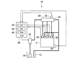
以下、本発明の実施の形態を図に基づいて説明する。本実施形態による燃料噴射システムを図1に示す。
(燃料噴射システム10)
燃料噴射システム10は、例えば、3気筒のディーゼルエンジン(以下、単に「エンジン」ともいう。)2に燃料を噴射するためのものである。燃料噴射システム10は、低圧ポンプ14と、高圧ポンプ16と、コモンレール20と、燃料噴射弁30と、電子制御装置(Electronic Control Unit:ECU)40とを備えている。
Hereinafter, embodiments of the present invention will be described with reference to the drawings. A fuel injection system according to this embodiment is shown in FIG.
(Fuel injection system 10)
The
電動の低圧ポンプ14は燃料タンク12から燃料を吸い上げて高圧ポンプ16に供給する。高圧ポンプ16は、カムシャフトのカムの回転に伴いプランジャが往復移動することにより、低圧ポンプ14から供給される燃料を加圧する公知のポンプである。高圧ポンプ16の燃料吸入側に設置された図示しない電磁弁を開閉することにより、高圧ポンプ16の吐出量が調量される。
The electric low-pressure pump 14 sucks fuel from the
コモンレール20は、高圧ポンプ16から吐出される燃料を蓄圧する中空の部材である。コモンレール20には、内部の燃料圧力(コモンレール圧)を検出する圧力センサ22、および、コモンレール圧が所定圧を超えると開弁してコモンレール20内の燃料を排出するプレッシャリミッタ24が設けられている。
The
エンジン2には、運転状態を検出するセンサとして、エンジン回転数(NE)を検出する回転数センサ32が設置されている。さらに、運転状態を検出する他のセンサとして、運転者によるアクセル操作量を示すアクセル開度(ACCP)を検出するアクセルセンサ、冷却水の温度(水温)、吸入空気の温度(吸気温)をそれぞれ検出する温度センサ等が燃料噴射システム10に設けられている。
The
燃料噴射弁30は、エンジン2の各気筒に設置されており、コモンレール20で蓄圧された燃料を気筒内に噴射する。燃料噴射弁30は、例えば、噴孔を開閉するノズルニードルのリフトを制御室の圧力で制御する公知の電磁弁である。燃料噴射弁30の噴射量は、ECU40から指令される噴射指令信号のパルス幅によって制御される。噴射指令信号のパルス幅が長くなると噴射量が増加する。
The
ECU40は、CPU42、RAM44、ROM46、および図示しないフラッシュメモリ等を中心とするマイクロコンピュータにて主に構成されている。ECU40は、ROM46またはフラッシュメモリに記憶されている制御プログラムをCPU42が実行することにより、圧力センサ22、回転数センサ32を含む各種センサから取り込んだ出力信号に基づき、燃料噴射システム10の各種制御を実行する。例えば、ECU40は、燃料噴射制御として、燃料噴射弁30の噴射量、噴射時期を制御する。
The ECU 40 is mainly configured by a microcomputer centering on a
ECU40は、燃料噴射弁30に噴射を指令する噴射指令信号のパルス幅(T)と噴射量(Q)との相関を示す所謂TQマップを、コモンレール圧の所定の圧力範囲毎にROM46またはフラッシュメモリに記憶している。そして、ECU40は、エンジン回転数およびアクセル開度等のエンジン運転状態に基づいて燃料噴射弁30の噴射量を決定すると、圧力センサ22が検出するコモンレール圧に応じて該当する圧力範囲のTQマップを参照し、決定した噴射量を燃料噴射弁30に指令する噴射指令信号のパルス幅をTQマップから取得する。
The
(噴射量学習)
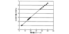
図2に示すように、噴射量と燃料噴射時の圧力低下量ΔPとは比例関係にあるので、圧力低下量ΔPが分かれば、燃料噴射弁30から実際に噴射される実噴射量Qrを式(1)から算出できる。圧力低下量ΔPは次式(2)から算出できる。
Qr=ΔP×V/E ・・・(1)
ΔP=Pbefore−Pafter ・・・(2)
式(1)において、V:コモンレール20および高圧配管を含む燃料噴射システム10の高圧部の容積、E:燃料の体積弾性係数である。また、式(2)において、Pbeforeは燃料噴射前のコモンレール圧である噴射前圧力を表わし、Pafterは燃料噴射後に圧力脈動が減衰しながら燃料圧力が低下して安定したときのコモンレール圧である噴射後圧力を表わしている。
(Injection amount learning)
As shown in FIG. 2, since the injection amount and the pressure drop amount ΔP at the time of fuel injection are in a proportional relation, if the pressure drop amount ΔP is known, the actual injection amount Qr actually injected from the
Qr = ΔP × V / E (1)
ΔP = Pbefore−Pafter (2)
In the formula (1), V is the volume of the high-pressure part of the
したがって、圧力センサ22の出力信号からPbeforeおよびPafterを取得できれば、式(2)から圧力低下量ΔPを算出して式(1)に代入することにより実噴射量Qrを算出できる。 Therefore, if Pbefore and Pafter can be acquired from the output signal of the pressure sensor 22, the actual injection amount Qr can be calculated by calculating the pressure drop amount ΔP from the equation (2) and substituting it into the equation (1).
燃料を噴射する前はコモンレール圧が安定しているので、圧力センサ22の出力信号から噴射前圧力Pbeforeを高精度に取得できる。一方、燃料噴射弁30が燃料を噴射して燃料圧力が低下するときには圧力脈動が生じる。そのため、圧力センサ22の出力信号から噴射後圧力Pafterを直接取得することは困難である。
Since the common rail pressure is stable before fuel is injected, the pre-injection pressure Pbefore can be obtained from the output signal of the pressure sensor 22 with high accuracy. On the other hand, when the
そこで、圧力脈動の平均値から噴射後圧力Pafterを取得することが考えられる。しかしながら、目標噴射量が所定量以下、例えば10mm3以下の微小量噴射時には、次に説明するように、圧力脈動の平均値から噴射後圧力Pafterを高精度に取得することは困難である。 Therefore, it is conceivable to obtain the post-injection pressure Pafter from the average value of pressure pulsations. However, when the target injection amount is a predetermined amount or less, for example, a small amount injection of 10 mm 3 or less, it is difficult to obtain the post-injection pressure Pafter with high accuracy from the average value of the pressure pulsation as described below.
図5に、燃料噴射時の燃料圧力の変化を示す。点線200は微小量噴射時の燃料圧力の変化を示し、実線202は目標噴射量が10mm3よりも多い通常噴射時の燃料圧力の変化を示している。
FIG. 5 shows changes in fuel pressure during fuel injection. A dotted
図5では、微少量噴射時と通常噴射時とにおける圧力低下量ΔPに対する圧力脈動の振幅ΔP’の大きさを比較するために、Pbefore、Pafter、ΔPを同じにして示しているが、当然のことながら、噴射量が減少するにしたがいΔPは小さくなる。 In FIG. 5, in order to compare the magnitude of the pressure pulsation amplitude ΔP ′ with respect to the pressure drop amount ΔP during the minute injection and during the normal injection, Pbefore, Pafter, and ΔP are shown to be the same. In fact, ΔP decreases as the injection amount decreases.
図5から分かるように、通常噴射時には、圧力低下量ΔPに対して圧力脈動の振幅ΔP’が小さいため、圧力脈動の平均値からPafterを所定の精度で算出できる。したがって、圧力センサ22の圧力信号から圧力脈動の大きさを取得し、圧力脈動の平均値から算出するPafterと圧力センサ22から取得するPbeforeとを式(2)に代入することにより圧力低下量ΔPを算出できる。そして、圧力低下量ΔPを式(1)に代入することにより実噴射量を算出できる。 As can be seen from FIG. 5, during normal injection, since the pressure pulsation amplitude ΔP ′ is smaller than the pressure drop amount ΔP, Pafter can be calculated with a predetermined accuracy from the average value of the pressure pulsations. Therefore, the magnitude of the pressure pulsation is obtained from the pressure signal of the pressure sensor 22, and the pressure drop amount ΔP is obtained by substituting Pafter calculated from the average value of the pressure pulsation and Pbefore obtained from the pressure sensor 22 into the equation (2). Can be calculated. Then, the actual injection amount can be calculated by substituting the pressure drop amount ΔP into the equation (1).
一方、微小量噴射時には、圧力低下量ΔPに対して圧力脈動の振幅ΔP’が大きいため、圧力脈動の平均値からPafterを所定の精度で算出することは困難である。
そこで、本願発明者は、燃料噴射時の圧力低下量ΔPに対する圧力脈動の振幅ΔP’の比が大きくなる微小量噴射領域では、噴射量の変化、つまり圧力低下量と圧力脈動の振幅とに相関関係があることに加え、圧力低下量の変化に対して圧力脈動の振幅の変化の感度が高いことに着目した。以下、燃料噴射時の圧力低下量と圧力脈動の振幅ΔP’との相関関係に基づいて圧力低下量を算出し、圧力低下量から実噴射量を算出する方法について説明する。
On the other hand, at the time of injection of a minute amount, since the pressure pulsation amplitude ΔP ′ is larger than the pressure drop amount ΔP, it is difficult to calculate Pafter from the average value of the pressure pulsation with a predetermined accuracy.
Therefore, the present inventor correlates with the change in the injection amount, that is, the pressure drop amount and the amplitude of the pressure pulsation in the minute amount injection region where the ratio of the pressure pulsation amplitude ΔP ′ to the pressure drop amount ΔP during fuel injection becomes large. In addition to the relationship, we focused on the high sensitivity of changes in pressure pulsation amplitude to changes in pressure drop. Hereinafter, a method of calculating the pressure drop amount based on the correlation between the pressure drop amount during fuel injection and the pressure pulsation amplitude ΔP ′ and calculating the actual injection amount from the pressure drop amount will be described.
まず、圧力脈動の振幅ΔP’は次式(3)で表わされる。式(3)において、PAmaxは圧力脈動の最大圧力を表わしている。
ΔP'=PAmax−Pafter ・・・(3)
図5に示すように、PAmaxは、駆動電流が燃料噴射弁30に供給されてから、噴射指令信号のパルス幅の時間と、駆動電流の供給が停止されてから燃料噴射弁30の噴射が終了するまでの噴射終了遅れ時間とを加算した合計時間が経過すると、所定時間内でコモンレール圧をサンプリングすることにより検出される。
First, the pressure pulsation amplitude ΔP ′ is expressed by the following equation (3). In equation (3), PAmax represents the maximum pressure pulsation.
ΔP ′ = PAmax−Pafter (3)
As shown in FIG. 5, PAmax is the time of the pulse width of the injection command signal after the drive current is supplied to the
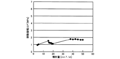
図2に示すように、噴射量が増加するにしたがい燃料噴射時の圧力低下量ΔPは大きくなる。これに対し、図3に示すように、燃料噴射時に生じる圧力脈動の振幅ΔP'は噴射量に関わらずほぼ一定である。これは、以下の理由による。 As shown in FIG. 2, the pressure drop amount ΔP during fuel injection increases as the injection amount increases. On the other hand, as shown in FIG. 3, the amplitude ΔP ′ of the pressure pulsation generated during fuel injection is substantially constant regardless of the injection amount. This is due to the following reason.
微小量噴射の場合、燃料噴射弁30の閉弁速度が通常噴射よりも速いため、水撃作用による圧力波が燃料噴射弁30とコモンレール20との間の高圧配管を往復して戻る前に燃料噴射弁30が閉弁する。
In the case of minute injection, since the valve closing speed of the
これにより、微小量噴射の場合、噴射量が微小なために通常噴射よりも高圧配管内の燃料の流速は遅いが、圧力脈動の最大圧力PAmaxは圧力低下量ΔP、つまり噴射量に対して大きくなる。 Thus, in the case of minute injection, the flow rate of fuel in the high-pressure pipe is slower than normal injection because the injection amount is minute, but the maximum pressure PAmax of pressure pulsation is larger than the pressure drop amount ΔP, that is, the injection amount. Become.
一方、通常噴射の場合、燃料噴射弁30の閉弁速度が微小量噴射よりも遅いため、燃料噴射弁30が閉弁する前に水撃作用による圧力波が燃料噴射弁30とコモンレール20との間の高圧配管を往復する。
On the other hand, in the case of normal injection, since the closing speed of the
その結果、燃料噴射弁30で遮断される前に圧力波の圧力が抜けるので、高圧配管内の燃料の流速は噴射量が大きいために微少量噴射よりも速いが、圧力脈動の最大圧力PAmaxは圧力低下量ΔP、つまり噴射量に対して小さくなる。
As a result, since the pressure wave pressure is released before being shut off by the
このように、微小量噴射時には高圧配管内の燃料の流速は遅いが圧力波の影響は大きくなり、通常噴射時には高圧配管内の燃料の流速は速いが圧力波の影響は小さくなるので、燃料噴射時に生じる圧力脈動の振幅は、噴射量に関わらずほぼ一定になる。 In this way, the flow rate of fuel in the high-pressure pipe is slow during micro injection, but the effect of pressure waves is large. In normal injection, the flow rate of fuel in the high-pressure pipe is fast, but the effect of pressure waves is small. The amplitude of the pressure pulsation that occurs sometimes becomes almost constant regardless of the injection amount.
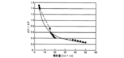
これにより、図4に示すように、噴射量と、圧力低下量ΔPに対する圧力脈動の振幅ΔP’の比(ΔP’/ΔP)との関係は反比例になる。圧力脈動の振幅ΔP’は噴射量に関わらず一定であるから、圧力低下量ΔPが小さくなるほど、つまり噴射量が小さくなるほど、圧力低下量ΔPに対して圧力脈動の振幅ΔP’は大きくなる。 As a result, as shown in FIG. 4, the relationship between the injection amount and the ratio (ΔP ′ / ΔP) of the pressure pulsation amplitude ΔP ′ to the pressure drop amount ΔP is inversely proportional. Since the pressure pulsation amplitude ΔP ′ is constant regardless of the injection amount, the smaller the pressure drop amount ΔP, that is, the smaller the injection amount, the greater the pressure pulsation amplitude ΔP ′ with respect to the pressure drop amount ΔP.
次式(4)に示すように(ΔP’/ΔP)をαで表わし、式(4)に式(2)、(3)を代入して整理すると、次式(5)が得られる。
ΔP’=α×ΔP ・・・(4)
PAmax−Pafter=α×(Pbefore−Pafter)
Pafter=Pbefore×α/(α−1)−PAmax×1/(α−1) ・・・(5)
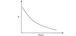
Pbeforeと比(α)との間には、図6に示すような特性の相関関係がある。この特性を表わすマップをROM46に記憶しておくことにより、マップに基づいてPbeforeに対応するαを取得できる。このαを式(4)に代入することにより、今回の噴射前圧力Pbeforeにおける圧力低下量ΔPと圧力脈動の振幅ΔP’との相関関係が規定される。
As shown in the following equation (4), (ΔP ′ / ΔP) is represented by α, and when the equations (2) and (3) are substituted into the equation (4) and rearranged, the following equation (5) is obtained.
ΔP ′ = α × ΔP (4)
PAmax−Pafter = α × (Pbefore−Pafter)
Pafter = Pbefore × α / (α−1) −PAmax × 1 / (α−1) (5)
There is a correlation of characteristics as shown in FIG. 6 between Pbefore and the ratio (α). By storing a map representing this characteristic in the
そして、式(4)を整理した式(5)に、αと、圧力センサ22から取得するPbeforeおよびPAmaxとを代入することによりPafterを算出できる。
Pbeforeと式(5)から算出したPafterとを式(2)に代入して圧力低下量ΔPを算出し、ΔPを式(1)に代入することにより実噴射量Qrを算出できる。
Then, Pafter can be calculated by substituting α and Pbefore and PAmax acquired from the pressure sensor 22 into Expression (5) obtained by rearranging Expression (4).
The actual injection amount Qr can be calculated by substituting Pbefore and Pafter calculated from equation (5) into equation (2) to calculate the pressure drop amount ΔP and substituting ΔP into equation (1).
図6のマップを用いず、Pafterを次式(6)が示すジューコフスキーの式から直接算出してもよい。
PAmax−Pafter=ρ×v0×a ・・・(6)
式(6)において、ρ:燃料密度、v0:流速、a:圧力波の速度、である。v0、aはそれぞれ次式(7)、(8)で表わされる。
v0={2×(Pbefore−Pafter)/ρ}1/2 ・・・(7)
a=(K/ρ)1/2 ・・・(8)
式(8)において、K:体積弾性係数、である。そして、式(7)および(8)を式(6)に代入することにより、圧力低下量ΔPと圧力脈動の振幅ΔP’との相関関係が規定される。
Instead of using the map of FIG. 6, Pafter may be directly calculated from the Zhukovsky equation represented by the following equation (6).
PAmax−Pafter = ρ × v0 × a (6)
In the equation (6), ρ: fuel density, v0: flow velocity, a: pressure wave velocity. v0 and a are represented by the following equations (7) and (8), respectively.
v0 = {2 * (Pbefore-Pafter) / [rho]} 1/2 (7)
a = (K / ρ) 1/2 (8)
In equation (8), K: bulk modulus. Then, by substituting Equations (7) and (8) into Equation (6), the correlation between the pressure drop amount ΔP and the pressure pulsation amplitude ΔP ′ is defined.
そして、式(7)および(8)を式(6)に代入して整理することにより、次式(9)からPafterを算出する。
Pafter=−K+PAmax+{(K−PAmax)2−PAmax2+2×K×Pbefore}1/2
・・・(9)
Pbeforeと式(9)から算出したPafterとを式(2)に代入して圧力低下量ΔPを算出し、ΔPを式(1)に代入することにより実噴射量Qrを算出できる。
Then, Pafter is calculated from the following equation (9) by substituting equations (7) and (8) into equation (6) and rearranging them.
Pafter = −K + PAmax + {(K−PAmax) 2 −PAmax 2 + 2 × K × Pbefore} 1/2
... (9)
The actual injection amount Qr can be calculated by substituting Pbefore and Pafter calculated from the equation (9) into the equation (2) to calculate the pressure drop amount ΔP and substituting ΔP into the equation (1).
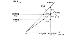
ECU40は、今回の微小量噴射で算出した実噴射量Qrと図7に示す基準特性210のマップとから、噴射指令値としての噴射指令信号のパルス幅を以下に説明するように補正する。
The
図7では、基準特性210と実際の実特性212とを一次式として示している。また、図7に示すTq0は、燃料噴射弁30が噴射を開始する最低パルス幅であり、基準特性210と実特性212とで最低パルス幅は同じであるとしている。
In FIG. 7, the
ECU40は、基準特性210の傾きと、微小量噴射において式(1)から算出する実噴射量Qrと目標噴射量Qtrgの指令パルス幅Tqとから決定される実特性212の傾きとの比を次式(10)から算出する。
{Qtrg/(Tq−Tq0)}/{Qr/(Tq−Tq0)}
=Qtrg/Qr ・・・(10)
式(10)で算出された基準特性210と実特性212との傾きの比は、図7に示すΔQ’とΔQとの比と等しい。ΔQは目標噴射量と実噴射量との差である。したがって、ΔQ’は次式(11)から算出できる。
ΔQ’=ΔQ×(Qtrg/Qr) ・・・(11)
ECU40は、基準特性210の傾き{Qtrg/(Tq−Tq0)}とΔQ’/ΔTqとが等しいことから、ΔQ’となるΔTqを次式(12)から算出する。
ΔTq=ΔQ’×(Tq−Tq0)/Qtrg ・・・(12)
式(12)から算出されたΔTqが、目標噴射量Qtrgとなる噴射指令信号のパルス幅Tqを補正する補正パルス幅である。
The
{Qtrg / (Tq-Tq0)} / {Qr / (Tq-Tq0)}
= Qtrg / Qr (10)
The ratio of the slope between the
ΔQ ′ = ΔQ × (Qtrg / Qr) (11)
The
ΔTq = ΔQ ′ × (Tq−Tq0) / Qtrg (12)
ΔTq calculated from Expression (12) is a correction pulse width for correcting the pulse width Tq of the injection command signal that becomes the target injection amount Qtrg.
次に、図8および図9のフローチャートに基づいて噴射量学習処理を説明する。図8および図9のフローチャートにおいて、「S」はステップを表わしている。図8および図9に示す噴射量学習処理は、常時実行してもよいし、燃料噴射弁30が経時変化したと判定されたときに実行してもよい。
Next, the injection amount learning process will be described based on the flowcharts of FIGS. In the flowcharts of FIGS. 8 and 9, “S” represents a step. The injection amount learning process shown in FIGS. 8 and 9 may be executed constantly or when it is determined that the
燃料噴射弁30は、例えば、所定走行距離に達したとき、あるいは気筒間で同じ目標噴射量のときに目標噴射量と実噴射量との差が所定量以上になったとき、あるいは気筒間の回転数変動のばらつきが所定値以上になったときに、経時変化したと判定される。
The
図8のフローチャートにおいてECU40は、燃料噴射弁30に噴射を指令する前の所定クランク角度になると(S400)、噴射前のコモンレール圧(Pbefore)を圧力センサ22から取得する(S402)。そして、噴射指令信号のパルス幅の時間と噴射終了遅れ時間との合計時間分、待機する(S404)。
In the flowchart of FIG. 8, the
待機時間が経過すると、ECU40は、所定レートで圧力センサ22の出力信号をサンプリングし、取得したコモンレール圧(Ptemp)をRAMに記憶する(S406)。
今回取得したPtempが前回までの最大圧力PAmaxよりも大きい場合には(S408:Yes)、ECU40はPtempをPAmaxとして設定する(S410)。今回取得したPtempが前回までの最大圧力PAmax以下の場合には(S408:No)、ECU40はS412に処理を移行する。PAmaxの初期値として例えば0が設定されている。
When the standby time has elapsed, the
When Ptemp acquired this time is larger than the maximum pressure PAmax until the previous time (S408: Yes), the
ECU40は、サンプリングを開始してからの経過時間(Tnow)が所定時間(TfCA)に達するまで(S412:Yes)、S406〜S410の処理を繰り返す。
経過時間(Tnow)が所定時間(TfCA)に達すると(S412:Yes)、ECU40は、前述したマップまたはジューコフスキーの式から噴射後のコモンレール圧(Pafter)を算出する(S414)。
The
When the elapsed time (Tnow) reaches a predetermined time (TfCA) (S412: Yes), the
Pafterを算出すると、ECU40は、PbeforeとPafterとを式(2)に代入して圧力低下量ΔPを算出し、ΔPを式(1)に代入して実噴射量Qrを算出する(S416)。
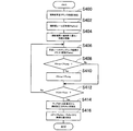
実噴射量を算出すると、ECU40は、図9のフローチャートに基づいて、噴射指令信号のパルス幅の補正値を算出する。
After calculating Pafter, the
When the actual injection amount is calculated, the
ECU40は、式(10)に基づいて実特性212の傾きに対する基準特性210の傾きの比を算出し(S420)、目標噴射量と実噴射量との差ΔQを算出する(S422)。
The
そして、ECU40は、基準特性210において目標噴射量と実噴射量との差ΔQに相当するΔQ’を式(11)から算出し(S424)、ΔQ’と基準特性210の傾きとに基づいて、式(12)から基準特性210においてΔQ’となるパルス幅ΔTqを算出する(S426)。このパルス幅ΔTqが、目標噴射量となる噴射指令信号のパルス幅Tqを補正する補正パルス幅である。
Then, the
以上説明した上記実施形態では、微小量噴射において、圧力低下量と圧力脈動の振幅とに相関関係があることに加え、圧力低下量の変化に対して圧力脈動の振幅の変化の感度が高いことに着目し、圧力脈動の振幅に基づいて微小量噴射時の圧力低下量を高精度に算出した。 In the above-described embodiment, in the minute injection, in addition to the correlation between the pressure drop amount and the pressure pulsation amplitude, the sensitivity of the change in the pressure pulsation amplitude to the change in the pressure drop amount is high. Focusing on the above, the amount of pressure drop at the time of minute injection was calculated with high accuracy based on the amplitude of pressure pulsation.
これにより、圧力低下量から実噴射量を算出し、目標噴射量と実噴射量との差に基づいて噴射指令信号のパルス幅を補正する学習方法において、圧力低下量に対して圧力脈動の振幅が大きい微小量噴射において、噴射指令信号を高精度に補正できる。 Thus, in the learning method of calculating the actual injection amount from the pressure decrease amount and correcting the pulse width of the injection command signal based on the difference between the target injection amount and the actual injection amount, the amplitude of the pressure pulsation with respect to the pressure decrease amount The injection command signal can be corrected with high accuracy in a small amount injection with a large.
[他の実施形態]
上記実施形態では、微小量噴射において、圧力脈動の振幅として圧力脈動の最大圧力に着目して圧力低下量と圧力脈動の振幅との相関関係を利用して実噴射量を算出したが、圧力脈動の振幅として圧力脈動の最低圧力に着目して圧力低下量と圧力脈動の振幅との相関関係を利用して実噴射量を算出してもよい。
[Other Embodiments]
In the above embodiment, in the small amount injection, the actual injection amount is calculated using the correlation between the pressure drop amount and the pressure pulsation amplitude by paying attention to the maximum pressure pulsation amplitude as the pressure pulsation amplitude. The actual injection amount may be calculated using the correlation between the pressure drop amount and the amplitude of the pressure pulsation by paying attention to the minimum pressure of the pressure pulsation as the amplitude of.
このように、本発明は、上記実施形態に限定されるものではなく、その要旨を逸脱しない範囲で種々の実施形態に適用可能である。 As described above, the present invention is not limited to the above-described embodiment, and can be applied to various embodiments without departing from the gist thereof.
2:ディーゼルエンジン(内燃機関)、30:燃料噴射弁、40:ECU(燃料噴射制御装置、圧力取得手段、低下量算出手段、噴射量算出手段、補正手段)、46:ROM(記憶手段) 2: diesel engine (internal combustion engine), 30: fuel injection valve, 40: ECU (fuel injection control device, pressure acquisition means, reduction amount calculation means, injection amount calculation means, correction means), 46: ROM (storage means)
Claims (3)
前記圧力取得手段が取得する前記燃料圧力に基づいて、燃料噴射時の前記燃料圧力の圧力低下量を算出する低下量算出手段(S408〜S416)と、
前記燃料噴射弁の実噴射量を前記圧力低下量に基づいて算出する噴射量算出手段(S416)と、
前記燃料噴射弁の目標噴射量と前記噴射量算出手段が算出する前記実噴射量との差に基づいて、前記燃料噴射弁に指令する噴射指令値を補正する補正手段(S420〜S426)と、
を備え、
前記目標噴射量が所定量以下の場合、前記低下量算出手段は、前記燃料噴射弁が燃料を噴射するときに生じる燃料の圧力脈動が減衰したときの前記燃料圧力の噴射後圧力を、前記噴射後圧力と前記燃料圧力の噴射前圧力と前記圧力脈動の最大圧力との相関関係を表わす式から算出し、前記噴射前圧力と前記噴射後圧力との差から前記圧力低下量を算出する、
ことを特徴とする燃料噴射制御装置(40)。 Pressure acquisition means (S402, S406) for acquiring fuel pressure accumulated in the pressure accumulation chamber (20) and supplied to the fuel injection valve (30);
A decrease amount calculating means (S408 to S416) for calculating a pressure decrease amount of the fuel pressure at the time of fuel injection based on the fuel pressure acquired by the pressure acquiring means;
Injection amount calculating means (S416) for calculating the actual injection amount of the fuel injection valve based on the pressure drop amount;
Correction means (S420 to S426) for correcting an injection command value commanded to the fuel injection valve based on a difference between a target injection amount of the fuel injection valve and the actual injection amount calculated by the injection amount calculation means;
With
When the target injection amount is less than or equal to a predetermined amount, the decrease amount calculation means calculates the post-injection pressure of the fuel pressure when the fuel pressure pulsation generated when the fuel injection valve injects the fuel is attenuated. Calculating from a formula representing a correlation between a post-pressure, a pre-injection pressure of the fuel pressure, and a maximum pressure of the pressure pulsation, and calculating the pressure decrease amount from a difference between the pre-injection pressure and the post-injection pressure ;
The fuel-injection control apparatus (40) characterized by the above-mentioned.
前記圧力取得手段が取得する前記燃料圧力に基づいて、燃料噴射時の前記燃料圧力の圧力低下量を算出する低下量算出手段(S408〜S416)と、
前記燃料噴射弁の実噴射量を前記圧力低下量に基づいて算出する噴射量算出手段(S416)と、
前記燃料噴射弁の目標噴射量と前記噴射量算出手段が算出する前記実噴射量との差に基づいて、前記燃料噴射弁に指令する噴射指令値を補正する補正手段(S420〜S426)と、
前記圧力低下量と前記燃料噴射弁が燃料を噴射するときに生じる燃料の圧力脈動の振幅との比と前記燃料圧力の噴射前圧力との相関関係を表わすマップが記憶されている記憶手段(46)と、
を備え、
前記目標噴射量が前記所定量以下の場合、前記低下量算出手段は、前記噴射前圧力に基づいて前記マップから前記比を取得し、前記圧力脈動が減衰したときの前記燃料圧力の噴射後圧力を、前記比と前記噴射後圧力と前記噴射前圧力と前記圧力脈動の最大圧力との相関関係を表わす式から算出し、前記噴射前圧力と前記噴射後圧力との差から前記圧力低下量を算出する、
ことを特徴とする燃料噴射制御装置(40)。 Pressure acquisition means (S402, S406) for acquiring fuel pressure accumulated in the pressure accumulation chamber (20) and supplied to the fuel injection valve (30);
A decrease amount calculating means (S408 to S416) for calculating a pressure decrease amount of the fuel pressure at the time of fuel injection based on the fuel pressure acquired by the pressure acquiring means;
Injection amount calculating means (S416) for calculating the actual injection amount of the fuel injection valve based on the pressure drop amount;
Correction means (S420 to S426) for correcting an injection command value commanded to the fuel injection valve based on a difference between a target injection amount of the fuel injection valve and the actual injection amount calculated by the injection amount calculation means;
Storage means (46) storing a map representing the correlation between the ratio of the pressure drop amount and the amplitude of the fuel pressure pulsation generated when the fuel injection valve injects fuel and the pre-injection pressure of the fuel pressure. )When,
With
When the target injection amount is less than or equal to the predetermined amount, the decrease amount calculation means acquires the ratio from the map based on the pre-injection pressure, and the post-injection pressure of the fuel pressure when the pressure pulsation is attenuated Is calculated from an equation representing the correlation between the ratio, the post-injection pressure, the pre-injection pressure, and the maximum pressure of the pressure pulsation, and the pressure drop amount is calculated from the difference between the pre-injection pressure and the post-injection pressure. calculate,
The fuel-injection control apparatus (40) characterized by the above-mentioned.
Priority Applications (1)
| Application Number | Priority Date | Filing Date | Title |
|---|---|---|---|
| JP2013033472A JP5994677B2 (en) | 2013-02-22 | 2013-02-22 | Fuel injection control device |
Applications Claiming Priority (1)
| Application Number | Priority Date | Filing Date | Title |
|---|---|---|---|
| JP2013033472A JP5994677B2 (en) | 2013-02-22 | 2013-02-22 | Fuel injection control device |
Publications (2)
| Publication Number | Publication Date |
|---|---|
| JP2014163260A JP2014163260A (en) | 2014-09-08 |
| JP5994677B2 true JP5994677B2 (en) | 2016-09-21 |
Family
ID=51614113
Family Applications (1)
| Application Number | Title | Priority Date | Filing Date |
|---|---|---|---|
| JP2013033472A Expired - Fee Related JP5994677B2 (en) | 2013-02-22 | 2013-02-22 | Fuel injection control device |
Country Status (1)
| Country | Link |
|---|---|
| JP (1) | JP5994677B2 (en) |
Families Citing this family (2)
| Publication number | Priority date | Publication date | Assignee | Title |
|---|---|---|---|---|
| JP6156397B2 (en) | 2015-01-14 | 2017-07-05 | トヨタ自動車株式会社 | Internal combustion engine |
| CN115596567B (en) * | 2022-10-26 | 2025-01-28 | 东风商用车有限公司 | A method, device, equipment and storage medium for adaptive compensation of fuel injection quantity |
Family Cites Families (2)
| Publication number | Priority date | Publication date | Assignee | Title |
|---|---|---|---|---|
| JP3849367B2 (en) * | 1999-09-20 | 2006-11-22 | いすゞ自動車株式会社 | Common rail fuel injection system |
| JP4996580B2 (en) * | 2008-10-30 | 2012-08-08 | 本田技研工業株式会社 | Fuel injection device |
-
2013
- 2013-02-22 JP JP2013033472A patent/JP5994677B2/en not_active Expired - Fee Related
Also Published As
| Publication number | Publication date |
|---|---|
| JP2014163260A (en) | 2014-09-08 |
Similar Documents
| Publication | Publication Date | Title |
|---|---|---|
| JP4075774B2 (en) | Injection quantity control device for diesel engine | |
| JP5212502B2 (en) | Fuel injection device | |
| US20150112576A1 (en) | Pump control apparatus for fuel supply system of fuel-injection engine | |
| JP2010261334A (en) | Fuel injection control device | |
| JP6221913B2 (en) | Pump control device | |
| JP6168016B2 (en) | Fuel density detector | |
| JP4710888B2 (en) | Diesel engine fuel injection control device and diesel engine fuel injection amount learning method | |
| JP5994677B2 (en) | Fuel injection control device | |
| JP4470975B2 (en) | Fuel injection control device and fuel injection system using the same | |
| JP4470976B2 (en) | Fuel injection control device and fuel injection system using the same | |
| JP5472151B2 (en) | Fuel injection device | |
| JP5110109B2 (en) | Fuel pressure control device | |
| JP5648646B2 (en) | Fuel injection control device | |
| JP5267441B2 (en) | Fuel injection device for internal combustion engine | |
| JP4788700B2 (en) | Fuel injection control device and fuel injection system using the same | |
| JP6303992B2 (en) | Fuel injection control device | |
| JP6036519B2 (en) | Fuel injection control device | |
| JP5218260B2 (en) | Fuel injection control device | |
| JP2011038449A (en) | Fuel injection control device | |
| WO2018061472A1 (en) | Vehicular control device | |
| JP6398631B2 (en) | Fuel injection status acquisition device | |
| JP5884710B2 (en) | Fuel pressure control device | |
| JP5338650B2 (en) | Accumulated fuel injection system | |
| JP2007303315A (en) | Common rail fuel injection device | |
| JP6094464B2 (en) | Fuel injection control device |
Legal Events
| Date | Code | Title | Description |
|---|---|---|---|
| A621 | Written request for application examination |
Free format text: JAPANESE INTERMEDIATE CODE: A621 Effective date: 20150518 |
|
| A977 | Report on retrieval |
Free format text: JAPANESE INTERMEDIATE CODE: A971007 Effective date: 20160212 |
|
| A131 | Notification of reasons for refusal |
Free format text: JAPANESE INTERMEDIATE CODE: A131 Effective date: 20160223 |
|
| A521 | Request for written amendment filed |
Free format text: JAPANESE INTERMEDIATE CODE: A523 Effective date: 20160420 |
|
| TRDD | Decision of grant or rejection written | ||
| A01 | Written decision to grant a patent or to grant a registration (utility model) |
Free format text: JAPANESE INTERMEDIATE CODE: A01 Effective date: 20160726 |
|
| A61 | First payment of annual fees (during grant procedure) |
Free format text: JAPANESE INTERMEDIATE CODE: A61 Effective date: 20160808 |
|
| R151 | Written notification of patent or utility model registration |
Ref document number: 5994677 Country of ref document: JP Free format text: JAPANESE INTERMEDIATE CODE: R151 |
|
| R250 | Receipt of annual fees |
Free format text: JAPANESE INTERMEDIATE CODE: R250 |
|
| R250 | Receipt of annual fees |
Free format text: JAPANESE INTERMEDIATE CODE: R250 |
|
| R250 | Receipt of annual fees |
Free format text: JAPANESE INTERMEDIATE CODE: R250 |
|
| R250 | Receipt of annual fees |
Free format text: JAPANESE INTERMEDIATE CODE: R250 |
|
| LAPS | Cancellation because of no payment of annual fees |