JP5994321B2 - Body front structure - Google Patents
Body front structure Download PDFInfo
- Publication number
- JP5994321B2 JP5994321B2 JP2012069998A JP2012069998A JP5994321B2 JP 5994321 B2 JP5994321 B2 JP 5994321B2 JP 2012069998 A JP2012069998 A JP 2012069998A JP 2012069998 A JP2012069998 A JP 2012069998A JP 5994321 B2 JP5994321 B2 JP 5994321B2
- Authority
- JP
- Japan
- Prior art keywords
- vehicle
- bumper
- vehicle body
- bumper member
- width direction
- Prior art date
- Legal status (The legal status is an assumption and is not a legal conclusion. Google has not performed a legal analysis and makes no representation as to the accuracy of the status listed.)
- Active
Links
Images


Classifications
-
- B—PERFORMING OPERATIONS; TRANSPORTING
- B60—VEHICLES IN GENERAL
- B60R—VEHICLES, VEHICLE FITTINGS, OR VEHICLE PARTS, NOT OTHERWISE PROVIDED FOR
- B60R19/00—Wheel guards; Radiator guards, e.g. grilles; Obstruction removers; Fittings damping bouncing force in collisions
- B60R19/02—Bumpers, i.e. impact receiving or absorbing members for protecting vehicles or fending off blows from other vehicles or objects
- B60R19/18—Bumpers, i.e. impact receiving or absorbing members for protecting vehicles or fending off blows from other vehicles or objects characterised by the cross-section; Means within the bumper to absorb impact
-
- B—PERFORMING OPERATIONS; TRANSPORTING
- B60—VEHICLES IN GENERAL
- B60R—VEHICLES, VEHICLE FITTINGS, OR VEHICLE PARTS, NOT OTHERWISE PROVIDED FOR
- B60R19/00—Wheel guards; Radiator guards, e.g. grilles; Obstruction removers; Fittings damping bouncing force in collisions
- B60R19/02—Bumpers, i.e. impact receiving or absorbing members for protecting vehicles or fending off blows from other vehicles or objects
- B60R19/04—Bumpers, i.e. impact receiving or absorbing members for protecting vehicles or fending off blows from other vehicles or objects formed from more than one section in a side-by-side arrangement
- B60R19/12—Bumpers, i.e. impact receiving or absorbing members for protecting vehicles or fending off blows from other vehicles or objects formed from more than one section in a side-by-side arrangement vertically spaced
-
- B—PERFORMING OPERATIONS; TRANSPORTING
- B60—VEHICLES IN GENERAL
- B60R—VEHICLES, VEHICLE FITTINGS, OR VEHICLE PARTS, NOT OTHERWISE PROVIDED FOR
- B60R19/00—Wheel guards; Radiator guards, e.g. grilles; Obstruction removers; Fittings damping bouncing force in collisions
- B60R19/02—Bumpers, i.e. impact receiving or absorbing members for protecting vehicles or fending off blows from other vehicles or objects
- B60R19/18—Bumpers, i.e. impact receiving or absorbing members for protecting vehicles or fending off blows from other vehicles or objects characterised by the cross-section; Means within the bumper to absorb impact
- B60R2019/1806—Structural beams therefor, e.g. shock-absorbing
-
- B—PERFORMING OPERATIONS; TRANSPORTING
- B60—VEHICLES IN GENERAL
- B60R—VEHICLES, VEHICLE FITTINGS, OR VEHICLE PARTS, NOT OTHERWISE PROVIDED FOR
- B60R19/00—Wheel guards; Radiator guards, e.g. grilles; Obstruction removers; Fittings damping bouncing force in collisions
- B60R19/02—Bumpers, i.e. impact receiving or absorbing members for protecting vehicles or fending off blows from other vehicles or objects
- B60R19/18—Bumpers, i.e. impact receiving or absorbing members for protecting vehicles or fending off blows from other vehicles or objects characterised by the cross-section; Means within the bumper to absorb impact
- B60R2019/186—Additional energy absorbing means supported on bumber beams, e.g. cellular structures or material
Description
本発明は、車体の前端に設置されるフロントバンパーを含む車体前部構造に関するものである。 The present invention relates to a vehicle body front part structure including a front bumper installed at a front end of a vehicle body.
車体前部構造としては、例えば、歩行者が車体に衝突した際に生じる車両前方からの衝撃荷重を衝撃吸収体で吸収することで、歩行者の脚部を保護するものが知られている(例えば、特許文献1)。 As a vehicle body front part structure, for example, a structure that protects a pedestrian's leg by absorbing an impact load from the front of the vehicle that occurs when the pedestrian collides with the vehicle body is known ( For example, Patent Document 1).
特許文献1には、第1の衝撃吸収体を備えた車体前部構造が記載されている。第1の衝撃吸収体は、車両前後方向に延びた一対のフレーム(本願発明のサイドメンバに相当)の前端にそれぞれ接続されたクラッシュカンと、クラッシュカン間に差し渡された車幅方向に延びるビーム部とを有する。また、この車体前部構造は、第1の衝撃吸収体に加え、ビーム部の下方を通ってバンパーフェイシアの裏面近傍まで延びていて、第1の衝撃吸収体よりも剛性が低い第2の衝撃吸収体も備えている。 Patent Document 1 describes a vehicle body front structure provided with a first shock absorber. The first shock absorber is connected to the front ends of a pair of frames (corresponding to the side members of the present invention) extending in the vehicle longitudinal direction, and extends in the vehicle width direction passed between the crash cans. And a beam portion. In addition to the first shock absorber, the vehicle body front portion structure extends to the vicinity of the back surface of the bumper fascia through the lower part of the beam portion, and has a second impact lower than that of the first shock absorber. It also has an absorber.
特許文献1では、第1の衝撃吸収体に加えて第2の衝撃吸収体を備えることで、衝撃荷重の吸収性を向上させ、歩行者保護性能を向上させるとしている。 In Patent Document 1, the second shock absorber is provided in addition to the first shock absorber, thereby improving the absorbability of the shock load and improving the pedestrian protection performance.
しかし、歩行者の脚部を十分に保護するためには、衝撃荷重を単に吸収するのみでなく、脚部の膝関節部へのせん断や曲げなどの負荷を緩和することが求められる。つまり、車体前部構造では、衝撃荷重を車両前端でどのように受け止めて吸収するかが重要である。 However, in order to sufficiently protect the legs of a pedestrian, it is required not only to absorb an impact load but also to relieve loads such as shearing and bending on the knee joints of the legs. That is, in the vehicle body front part structure, it is important how to receive and absorb the impact load at the front end of the vehicle.
特許文献1に記載の車体前部構造のように、衝撃荷重の吸収性を向上させるだけでは、歩行者の脚部を十分に保護することは困難である。 As in the vehicle body front structure described in Patent Document 1, it is difficult to sufficiently protect the pedestrian's legs only by improving the absorbability of the impact load.
本発明は、このような課題に鑑み、歩行者保護性能を向上できる車体前部構造を提供することを目的としている。 In view of such a problem, an object of the present invention is to provide a vehicle body front structure capable of improving pedestrian protection performance.
上記課題を解決するために、本発明にかかる車体前部構造の代表的な構成は、車体の前端に設置されるフロントバンパーを含む車体前部構造において、フロントバンパーの後側で車幅方向に間隔をおいて配置された車両前後方向に延びている一対のサイドメンバと、車幅方向に延びていて一対のサイドメンバの前端部に両端部が接続されたバンパーメンバと、バンパーメンバの後側の空隙と、バンパーメンバの前側に配置され車両前方からの衝撃を吸収する車幅方向に延びるアブソーバーと、バンパーメンバの上方に配置された車幅方向に延びるアッパーメンバであってアッパーメンバの前端がバンパーメンバの、車両前後方向におけるわずかに後ろに位置するアッパーメンバとを備え、バンパーメンバは一枚板で形成されていて、車両前方に突出した車幅方向全体にわたる突出部を形成していて、突出部は、車両前後方向よりも車両上下方向に長い形状を有することを特徴とする。 In order to solve the above problems, a typical structure of the vehicle body front structure according to the present invention is a vehicle body front structure including a front bumper installed at the front end of the vehicle body. A pair of side members extending in the vehicle longitudinal direction, a bumper member extending in the vehicle width direction and having both ends connected to the front end portions of the pair of side members, and a gap on the rear side of the bumper member And an absorber extending in the vehicle width direction that is disposed on the front side of the bumper member and absorbs an impact from the front of the vehicle, and an upper member that is disposed above the bumper member and extends in the vehicle width direction, and the front end of the upper member is the bumper member of slightly and a upper member located behind the vehicle front-bumper member is formed of a single plate, the front of the vehicle Form a protrusion over the entire protruding vehicle width direction, the protrusions, characterized by having a long shape in the vertical direction of the vehicle than the vehicle front-rear direction.
上記の構成において、車体に正対する歩行者の脚部が車体の中央付近に衝突し、これによってフロントバンパーが前方からの衝撃荷重を受けた場合を想定する。フロントバンパーが衝撃荷重を受けると、その後側に位置し閉断面を形成していない一枚板のバンパーメンバがまず潰れてエネルギーを吸収する。バンパーメンバの後側には空隙が存在するので、バンパーメンバは、車両中央付近が後側に弓なりに変形する。さらに、バンパーメンバに対しては、その両端部に接続された一対のサイドメンバより引張り力が作用する。これによってバンパーメンバは、衝撃荷重に伴うエネルギーを吸収し、変形を完了する。その後、アブソーバーが潰れることで、エネルギーはさらに吸収される。また、アッパーメンバの前端は、バンパーメンバの、車両前後方向におけるわずかに後ろに位置するので、エネルギーを吸収して潰れたバンパーメンバおよびアブソーバーの位置は、車両前後方向でアッパーメンバの前端よりも車両後方に位置することになる。その結果、衝突した歩行者の脚部のうち、膝関節部を境界とした下側部は、上側部よりも車両後方に位置する。このような位置関係であれば、膝関節部への衝撃を緩和することができる。なお、歩行者の脚部のうち大腿部に相当する上側部の位置は、アッパーメンバの位置に対応している。歩行者の脚部のうち下腿部に相当する下側部の位置は、バンパーメンバおよびアブソーバーの位置に対応している。 In the above configuration, it is assumed that the pedestrian's leg portion facing the vehicle body collides with the vicinity of the center of the vehicle body, thereby causing the front bumper to receive an impact load from the front. When the front bumper receives an impact load, a single-plate bumper member that is located on the rear side and does not form a closed cross section first collapses to absorb energy. Since a gap exists on the rear side of the bumper member, the bumper member is deformed like a bow on the rear side near the center of the vehicle. Further, a tensile force acts on the bumper member from a pair of side members connected to both ends thereof. As a result, the bumper member absorbs the energy accompanying the impact load and completes the deformation. Thereafter, the energy is further absorbed by the collapse of the absorber. Further, since the front end of the upper member is located slightly behind the bumper member in the vehicle front-rear direction , the positions of the bumper member and the absorber that have been crushed by absorbing the energy are higher than the front end of the upper member in the vehicle front-rear direction. It will be located behind. As a result, among the legs of the colliding pedestrian, the lower side with the knee joint as the boundary is located behind the vehicle relative to the upper side. With such a positional relationship, the impact on the knee joint can be reduced. In addition, the position of the upper part corresponding to the thigh among the legs of the pedestrian corresponds to the position of the upper member. The position of the lower part corresponding to the lower leg part of the leg part of the pedestrian corresponds to the positions of the bumper member and the absorber.
言い換えると、上記構成によれば、バンパーメンバを積極的に変形させることができ、さらに、アッパーメンバの前端に対して最適な位置関係になるように、アブソーバーおよびバンパーメンバを後退させることが可能となる。その結果として、歩行者の脚部の膝関節部へのせん断や曲げなどの負荷を緩和し、歩行者の脚部の保護性能を向上できる。なお、本明細書では、車体に正対する歩行者に対して、車体が極端な速度(すなわち、150km/hあるいは5km/h)で衝突することは想定していず、例えば20−40km/h程度の所定の速度で衝突するような状況を前提としている。 In other words, according to the above configuration, the bumper member can be positively deformed, and further, the absorber and the bumper member can be retracted so as to have an optimum positional relationship with respect to the front end of the upper member. Become. As a result, it is possible to alleviate loads such as shearing and bending on the knee joint of the pedestrian's leg, and improve the protection performance of the pedestrian's leg. In this specification, it is not assumed that the vehicle body collides with a pedestrian facing the vehicle body at an extreme speed (that is, 150 km / h or 5 km / h), for example, about 20-40 km / h. It is assumed that the vehicle will collide at a predetermined speed.
本発明によれば、歩行者保護性能を向上できる車体前部構造を提供することができる。 ADVANTAGE OF THE INVENTION According to this invention, the vehicle body front part structure which can improve a pedestrian protection performance can be provided.
以下に添付図面を参照しながら、本発明の好適な実施形態について詳細に説明する。かかる実施形態に示す寸法、材料、その他具体的な数値などは、発明の理解を容易とするための例示に過ぎず、特に断る場合を除き、本発明を限定するものではない。なお、本明細書及び図面において、実質的に同一の機能、構成を有する要素については、同一の符号を付することにより重複説明を省略し、また本発明に直接関係のない要素は図示を省略する。 Hereinafter, preferred embodiments of the present invention will be described in detail with reference to the accompanying drawings. The dimensions, materials, and other specific numerical values shown in the embodiments are merely examples for facilitating understanding of the invention, and do not limit the present invention unless otherwise specified. In the present specification and drawings, elements having substantially the same function and configuration are denoted by the same reference numerals, and redundant description is omitted, and elements not directly related to the present invention are not illustrated. To do.
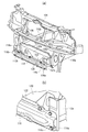
図1は、本実施形態における車体前部構造の概略構成を示す図である。図2は、図1の車体前部構造からフロントバンパーを取り外した状態を示す図である。図3は、図2の車体前部構造からアブソーバーを取り外した状態を示す図である。図3(a)は、車体前部構造の車両前方側の概略構成を示す図である。図3(b)は、図3(a)の一部を拡大して示す図である。 FIG. 1 is a diagram showing a schematic configuration of a vehicle body front portion structure in the present embodiment. FIG. 2 is a view showing a state in which the front bumper is removed from the vehicle body front part structure of FIG. FIG. 3 is a view showing a state where the absorber is removed from the vehicle body front part structure of FIG. 2. FIG. 3A is a diagram showing a schematic configuration of the vehicle front portion structure on the vehicle front side. FIG. 3B is an enlarged view of a part of FIG.
車体前部構造100は、図1に示すように、車体の前端にフロントバンパー102が設置されている。フロントバンパー102は、外装となるバンパーフェイシア104を含む。バンパーフェイシア104の上部104aは、図2および図3(a)に示す車幅方向に延びるアッパーメンバ106に沿うように配置されている。また、アッパーメンバ106の車両上側には、車幅方向に延びていて不図示のフードを支持するフードメンバ108が配置されている。
As shown in FIG. 1, the vehicle body
車体前部構造100は、上記各部材に加え、図2に示すように車両前後方向に延びている一対のサイドメンバ110a、110bと、一対のクラッシュカン112a、112bおよび支持部材114a、114bと、バンパーメンバ116と、アブソーバー118と、クロスメンバ120とを備える。
The vehicle
クラッシュカン112a、112bは、車両前後方向に延びる衝撃吸収部材であり、サイドメンバ110a、110bの前端に接続されている。支持部材114a、114bは、クラッシュカン112a、112bの前端に接続された部材であり、図3(a)に示すようにバンパーメンバ116を支持している。
The
バンパーメンバ116は、図3(a)に示すように車幅方向に延びていて、両端部116a、116bが支持部材114a、114bにそれぞれ接続されている。また、バンパーメンバ116は、例えば金属製の一枚板で形成された部材であり、図3(b)の端部116aに示すように閉断面を形成せず、車両後方に向かって開放された形状を有する。アブソーバー118は、図2に示すように車幅方向に延びる部材であり、バンパーメンバ116の車両前側に配置されていて、車両前方からの衝撃を吸収する。
As shown in FIG. 3A, the
クロスメンバ120は、車幅方向に延びる部材であり、バンパーメンバ116の後方に位置している。バンパーメンバ116とクロスメンバ120との間には、図2、図3(a)および図3(b)に示すように、空隙122が介在している。クロスメンバ120は、図2および図3(a)に示すように、車両前側に位置するクロスメンバーファーストフロント(以下、前側クロスメンバ120a)と、車両後側に位置するクロスメンバーファーストリア(以下、後側クロスメンバ120b)とを含んでいる。なお、前側クロスメンバ120aと後側クロスメンバ120bとは閉断面を形成している。
The
図4は、図1の車体前部構造100の一部を車両後方側の上方から見た状態を示す図である。図4(a)は、フロントバンパー102およびクロスメンバ120を示す図である。図4(b)は、フロントバンパー102、バンパーメンバ116およびアブソーバー118を示す図である。
FIG. 4 is a diagram illustrating a state in which a part of the vehicle
フロントバンパー102のバンパーフェイシア104は、図示のように、車両後方に向かって延びている下部104bを備える。バンパーフェイシア104の下部104bは、車幅方向に並んで形成された3つの台座124a、124b、124c(図4(a)参照)と、台座124a、124b、124cよりも車両前側で車幅方向に並んで形成された2つの台座126a、126b(図4(b)参照)とを有する。
The
台座124a、124bは、図4(a)に示すように、ブラケット128a、128bを介して後側クロスメンバ120bに接続されている。台座124cは、ブラケット128cを介して前側クロスメンバ120aに接続されている。このようにして、フロントバンパー102は、クロスメンバ120に接続される。
As shown in FIG. 4A, the
台座126a、126bは、図4(b)に示すように、ブラケット130a、130bを介してバンパーメンバ116に接続されている。このようにして、フロントバンパー102は、バンパーメンバ116に接続される。なお、バンパーメンバ116は、車両前側でアブソーバー118を保持している。
As shown in FIG. 4B, the
以下、図5〜図7を参照して、歩行者の脚部を模した衝突子200が矢印Bに示すように車両前側から車体前部構造100に衝突した場合での、車体前部構造100の挙動について説明する。なお本実施形態では、車体に正対する歩行者の脚部が車体の中央付近に衝突し、これによってフロントバンパー102が前方からの衝撃荷重を受けた場合を想定している。この場合、車体に正対する歩行者に対して、車体が例えば20−40km/h程度の所定の速度で衝突するような状況を前提としている。
Hereinafter, with reference to FIG. 5 to FIG. 7, the vehicle
図5は、図1の車体前部構造100のA−A断面図である。図5(a)は、車体前部構造100のA−A断面を衝突子200とともに示す図である。図5(b)は、図5(a)のバンパーメンバ116を拡大して示す図である。
FIG. 5 is a cross-sectional view of the vehicle
衝突子200は、図5(a)に示すように、上側部202と、下側部204と、膝関節部206とを含む。上側部202は、歩行者の脚部の大腿部を模している部分である。上側部202の位置は、アッパーメンバ106の位置に対応している。下側部204は、歩行者の脚部の下腿部を模している部分である。下側部204の位置は、バンパーメンバ116およびアブソーバー118の位置に対応している。膝関節部206は、歩行者の膝関節部を模した部分である。
As shown in FIG. 5A, the
アッパーメンバ106は、バンパーメンバ116の上方に配置され車幅方向に延びる部材であり、さらに図5(a)の鎖線Cに示すように、その前端106aがバンパーメンバ116の、車両前後方向におけるわずかに後ろに位置している。また、バンパーメンバ116の後側には、上記空隙122が存在している。
The
バンパーメンバ116は、図5(b)に示すように、側面視での断面形状が閉断面を形成せず、車両後方に向かって開放された形状を有する。より具体的には、バンパーメンバ116は、車両前方に突出した車幅方向全体にわたる突出部132を形成している。突出部132は、車両前側に位置する縦壁部134と、傾斜部136a、136bとを有する。傾斜部136a、136bは、例えば縦壁部134から連続し車両後方に向かって、それぞれ車両上側、車両下側に傾斜している。
As shown in FIG. 5B, the
また、突出部132の車両上下方向の寸法Laは、図示のように、車両前後方向の寸法Lbよりも大きい。つまり、突出部132は、車両前後方向よりも車両上下方向に長い形状を有する。なお、バンパーメンバ116は、フランジ部138a、138bを有する。フランジ部138a、138bは、傾斜部136a、136bから連続し車両上側、車両下側に向かってそれぞれ張り出している。
Further, the dimension La of the
このように、バンパーメンバ116は、車両前後方向よりも車両上下方向に長い形状を有する突出部132を形成し、さらに、閉断面を形成せず車両後方に向かって開放されている。このため、バンパーメンバ116は、車両前後方向の衝撃に対して剛性が低く、かつ、車両上下方向の衝撃に対しては剛性が高くなっている。
As described above, the
図6は、図5の車両前部構造100の一部を示す上面図である。図6では、便宜上、フロントバンパー102、アッパーメンバ106およびフードメンバ108を省略して示している。図7は、図5の車両前部構造100に衝突子200が衝突した状態を示す図である。なお、衝突子200が衝突する前の状態は、図中仮想線で示している。
FIG. 6 is a top view showing a part of the
衝突子200が矢印Bに示すように車体前方から衝突すると、まず、車両前後方向の衝撃に対して剛性が低いバンパーメンバ116の断面が潰れ、衝突エネルギーを吸収する。バンパーメンバ116の後側には空隙122が存在する。このため、バンパーメンバ116は、図6の鎖線Dに示すように、車両中央付近がクロスメンバ120に近付くように後方に弓なりに変形する。言い換えると、空隙122が存在するので、バンパーメンバ116は、後方に変形できる。
When the
さらに、バンパーメンバ116は、上記したように、両端部116a、116bが支持部材114a、114b、クラッシュカン112a、112bを介してサイドメンバ110a、110bに接続されている。このため、バンパーメンバ116に対しては、その両端部116a、116bに接続されたサイドメンバ110a、110bから矢印E、Fに示すように車幅方向に引張り力が作用する。これによって、バンパーメンバ116は、衝突エネルギーを吸収し、鎖線Dで示すように変形を完了する。
Furthermore, as described above, the
バンパーメンバ116の変形が完了すると、続いてアブソーバー118が後方に潰れる。これにより、衝突エネルギーは、アブソーバー118によってさらに吸収される。後方に変形し潰れたバンパーメンバ116およびアブソーバー118の位置は、図7の鎖線Gに示すように、アッパーメンバ106の前端106aよりも車両後方に位置する。
When the deformation of the
このように、バンパーメンバ116およびアブソーバー118の変形に伴い衝突エネルギーが吸収されることで、衝突子200の下側部204は、減速しながら車両後方に向かって進行する。衝突子200の上側部202は、例えば慣性力によりアッパーメンバ106の前端106aに接触するまで車両後方に向かって進行する。なお、本実施形態で想定している所定の速度で歩行者の脚部が車体前部構造100に衝突したとき、バンパーメンバ116はクロスメンバ120には接触しないとする。
Thus, the collision energy is absorbed along with the deformation of the
そして、バンパーメンバ116およびアブソーバー118は、アッパーメンバ106の前端106aよりも車両後方に位置するまで変形し後退しながら衝突エネルギーを吸収する。その結果、衝突子200は、図7に示すように、下側部204が上側部202よりも車両後方に位置する。このような位置関係であれば、衝突子200の膝関節部206への衝撃が緩和され、いわば最適な位置関係を得ることができる。
The
ところで、既存の車体前部構造では、単に、バンパーフェイシアの内部に、バンパーメンバと、バンパーメンバの前側に配置されたアブソーバーとを配置し、歩行者の脚部が衝突した際にアブソーバーを潰すことで衝突エネルギーを吸収し、歩行者への被害を緩和させていた。 By the way, in the existing vehicle front structure, a bumper member and an absorber arranged on the front side of the bumper member are simply arranged inside the bumper fascia, and the absorber is crushed when a pedestrian's leg collides. It absorbed the collision energy and eased the damage to pedestrians.
また、車体前部構造では、車体の居住空間や荷室容量を確保するために、コンパクト化が求められている。その一方で、車体前部構造では、衝突時の乗員の保護のために、強固な一対のサイドメンバを車両前後方向により延長した構成も求められている。これらの要請を考慮すると、車体前部構造は、バンパーフェイシアとバンパーメンバとの間に、例えばアブソーバーを配置するための空隙を確保することが困難となり、衝突エネルギーを十分に吸収することができない場合があり得る。 In addition, the vehicle body front structure is required to be compact in order to secure the living space of the vehicle body and the cargo space capacity. On the other hand, in the vehicle body front structure, a configuration in which a pair of strong side members is extended in the vehicle front-rear direction is also required in order to protect passengers in the event of a collision. Considering these requirements, it is difficult for the vehicle body front structure to sufficiently absorb the collision energy because it becomes difficult to secure a gap for arranging, for example, the absorber between the bumper fascia and the bumper member. There can be.
また、歩行者の脚部を保護するためには、歩行者の脚部の膝関節部へのせん断や曲げなどの負荷を緩和することが求められる。そのため、車体前部構造では、車両前方からの衝突エネルギーを車体前端でどのように受け止めるかが重要である。しかし、既存の車体前部構造では、衝突エネルギーをどのように受け止めるかは、車体前端に配置された各部材(車体構造物)のレイアウトに依存する場合がある。しかも、車体構造物のレイアウトは、車体の意匠、あるいは衝突時の乗員保護に大きく寄与することから、歩行者脚部保護の観点からは不利なレイアウトとなる場合もあった。 Moreover, in order to protect a leg part of a pedestrian, it is calculated | required to ease loads, such as a shear and bending to the knee joint part of a pedestrian's leg part. Therefore, in the vehicle body front structure, it is important how the collision energy from the front of the vehicle is received at the vehicle front end. However, in the existing vehicle body front structure, how collision energy is received may depend on the layout of each member (vehicle body structure) disposed at the vehicle body front end. In addition, the layout of the vehicle body structure greatly contributes to the design of the vehicle body or the occupant protection in the event of a collision, which may be a disadvantageous layout from the viewpoint of protecting the pedestrian legs.
これに対して、本実施形態の車体前部構造100では、上記したように、アブソーバー118を保持するバンパーメンバ116は、閉断面を形成せず車両後方に向かって開放されている。また、バンパーメンバ116の後側には、空隙122が存在している。このため、車体前部構造100では、バンパーメンバ116が積極的に変形して衝突エネルギーを吸収し、この変形が終了すると、続いてアブソーバー118が潰れて後退しながら衝突エネルギーをさらに吸収できる。
On the other hand, in the vehicle
その結果、車体前部構造100では、アッパーメンバ106の前端106aに対して、バンパーメンバ116およびアブソーバー118が車両後方に位置する、最適な位置関係となる。つまり、衝突子200では、図7に示すように、下側部204が上側部202よりも車両後方に位置する。このような位置関係であれば、衝突子200の膝関節部206への衝撃を緩和することができる。したがって、車体前部構造100は、歩行者の脚部の膝関節部へのせん断や曲げなどの負荷を緩和し、歩行者の脚部の保護性能を向上できる。
As a result, in the vehicle
なお、車体前部構造100では、バンパーメンバ116を積極的に変形させ、バンパーメンバ116およびアブソーバー118を適切な位置まで後退させることで、歩行者の脚部の保護性能を向上できる。このため、仮に、上記車体構造物のレイアウトが歩行者脚部保護の観点から不利な車両であっても、車体前部構造100を適用することで、歩行者保護性能を向上できる。
In the vehicle
上記実施形態では、バンパーメンバ116を金属製の部材としたが、これに限定されず、衝撃時の割れに強く、引張り方向の入力に対して高強度であれば樹脂など適宜の材料で形成してもよい。
In the above embodiment, the
以上、添付図面を参照しながら本発明の好適な実施形態について説明したが、本発明は係る例に限定されないことは言うまでもない。当業者であれば、特許請求の範囲に記載された範疇内において、各種の変更例または修正例に想到し得ることは明らかであり、それらについても当然に本発明の技術的範囲に属するものと了解される。 As mentioned above, although preferred embodiment of this invention was described referring an accompanying drawing, it cannot be overemphasized that this invention is not limited to the example which concerns. It will be apparent to those skilled in the art that various changes and modifications can be made within the scope of the claims, and these are naturally within the technical scope of the present invention. Understood.
本発明は、車体の前端に設置されるフロントバンパーを含む車体前部構造に利用することができる。 The present invention can be used for a vehicle body front structure including a front bumper installed at the front end of the vehicle body.
100…車体前部構造、102…フロントバンパー、104…バンパーフェイシア、104a…上部、104b…下部、106…アッパーメンバ、106a…前端、108…フードメンバ、110a、110b…サイドメンバ、112a、112b…クラッシュカン、114a、114b…支持部材、116…バンパーメンバ、116a、116b…両端部、118…アブソーバー、120…クロスメンバ、120a…前側クロスメンバ、120b…後側クロスメンバ、122…空隙、124a、124b、124c、126a、126b…台座、128a、128b、128c、130a、130b…ブラケット、132…突出部、134…縦壁部、136a、136b…傾斜部、138a、138b…フランジ部、200…衝突子、202…上側部、204…下側部、206…膝関節部
DESCRIPTION OF
Claims (1)
前記フロントバンパーの後側で車幅方向に間隔をおいて配置された車両前後方向に延びている一対のサイドメンバと、
車幅方向に延びていて前記一対のサイドメンバの前端部に両端部が接続されたバンパーメンバと、
前記バンパーメンバの後側の空隙と、
前記バンパーメンバの前側に配置され車両前方からの衝撃を吸収する車幅方向に延びるアブソーバーと、
前記バンパーメンバの上方に配置された車幅方向に延びるアッパーメンバであって該アッパーメンバの前端が前記バンパーメンバの、車両前後方向におけるわずかに後ろに位置するアッパーメンバとを備え、
前記バンパーメンバは一枚板で形成されていて、車両前方に突出した車幅方向全体にわたる突出部を形成していて、該突出部は、車両前後方向よりも車両上下方向に長い形状を有し、
前記バンパーメンバは、前記フロントバンパーの外装となるバンパーフェイシアの車両後方に向かって延びる下部に配置されていることを特徴とする車体前部構造。 In the vehicle body front structure including the front bumper installed at the front end of the vehicle body,
A pair of side members extending in the vehicle front-rear direction and spaced apart in the vehicle width direction on the rear side of the front bumper;
A bumper member extending in the vehicle width direction and having both ends connected to the front ends of the pair of side members;
A gap on the rear side of the bumper member;
An absorber that is arranged on the front side of the bumper member and extends in the vehicle width direction for absorbing impact from the front of the vehicle;
An upper member disposed above the bumper member and extending in the vehicle width direction, and a front end of the upper member is located slightly behind the bumper member in the vehicle front-rear direction; and
The bumper member is formed of a single plate, to thereby form a protrusion over the entire vehicle width direction which projects forward of the vehicle, projecting portion, the elongated possess in the vehicle vertical direction than the vehicle front-rear direction ,
The bumper member, the vehicle body front structure which is characterized that you have been placed in the lower extending toward the vehicle rear bumper fascia made the exterior of the front bumper.
Priority Applications (4)
| Application Number | Priority Date | Filing Date | Title |
|---|---|---|---|
| JP2012069998A JP5994321B2 (en) | 2012-03-26 | 2012-03-26 | Body front structure |
| US13/840,064 US8651559B2 (en) | 2012-03-26 | 2013-03-15 | Vehicle body front structure |
| DE102013204767.3A DE102013204767B4 (en) | 2012-03-26 | 2013-03-19 | Vehicle body front structure |
| CN201310095055.0A CN103359028B (en) | 2012-03-26 | 2013-03-22 | Vehicle body front structure |
Applications Claiming Priority (1)
| Application Number | Priority Date | Filing Date | Title |
|---|---|---|---|
| JP2012069998A JP5994321B2 (en) | 2012-03-26 | 2012-03-26 | Body front structure |
Publications (3)
| Publication Number | Publication Date |
|---|---|
| JP2013199250A JP2013199250A (en) | 2013-10-03 |
| JP2013199250A5 JP2013199250A5 (en) | 2015-04-16 |
| JP5994321B2 true JP5994321B2 (en) | 2016-09-21 |
Family
ID=49112420
Family Applications (1)
| Application Number | Title | Priority Date | Filing Date |
|---|---|---|---|
| JP2012069998A Active JP5994321B2 (en) | 2012-03-26 | 2012-03-26 | Body front structure |
Country Status (4)
| Country | Link |
|---|---|
| US (1) | US8651559B2 (en) |
| JP (1) | JP5994321B2 (en) |
| CN (1) | CN103359028B (en) |
| DE (1) | DE102013204767B4 (en) |
Families Citing this family (7)
| Publication number | Priority date | Publication date | Assignee | Title |
|---|---|---|---|---|
| JP5969417B2 (en) * | 2013-03-25 | 2016-08-17 | 富士重工業株式会社 | Body front structure |
| US9016766B2 (en) * | 2013-04-24 | 2015-04-28 | GM Global Technology Operations LLC | Energy dissipation system for vehicles |
| JP6102478B2 (en) * | 2013-05-08 | 2017-03-29 | スズキ株式会社 | Vehicle front structure |
| US10688948B2 (en) * | 2016-07-28 | 2020-06-23 | Tiercon Corp | Automotive vehicle bumper assembly |
| EP3953201B1 (en) * | 2019-04-10 | 2023-01-11 | Volvo Truck Corporation | A vehicle comprising a battery protection structure |
| US11014611B2 (en) * | 2019-04-11 | 2021-05-25 | Hyundai Motor Company | Front body of vehicle |
| CN112758034B (en) * | 2021-01-05 | 2023-03-14 | 重庆长安汽车股份有限公司 | Pedestrian leg protection structure |
Family Cites Families (20)
| Publication number | Priority date | Publication date | Assignee | Title |
|---|---|---|---|---|
| JP2002178862A (en) * | 2000-12-18 | 2002-06-26 | Fuji Heavy Ind Ltd | Bumper face fitting structure |
| JP2003011750A (en) * | 2001-07-05 | 2003-01-15 | Fuji Heavy Ind Ltd | Bumper structure for automobile |
| JP2004058726A (en) * | 2002-07-25 | 2004-02-26 | Fuji Heavy Ind Ltd | Bumper structure for automobile |
| DE10324460A1 (en) * | 2003-05-30 | 2004-12-16 | Volkswagen Ag | Bumper arrangement for a vehicle, in particular for a motor vehicle |
| JP2005306161A (en) * | 2004-04-20 | 2005-11-04 | Asteer Co Ltd | Bumper device |
| US7073831B2 (en) * | 2004-06-23 | 2006-07-11 | Netshape International Llc | Bumper with crush cones and energy absorber |
| US7163243B2 (en) * | 2004-12-13 | 2007-01-16 | Netshape International, Llc | Bumper for pedestrian impact having thermoformed energy absorber |
| JP2006256463A (en) * | 2005-03-16 | 2006-09-28 | Toyota Motor Corp | Front bumper structure |
| JP4389847B2 (en) * | 2005-06-27 | 2009-12-24 | トヨタ自動車株式会社 | Vehicle front structure |
| US7455351B2 (en) * | 2006-02-15 | 2008-11-25 | Mazda Motor Corporation | Vehicle front end structure |
| JP4797726B2 (en) * | 2006-03-20 | 2011-10-19 | マツダ株式会社 | Automotive front structure |
| JP4872541B2 (en) * | 2006-08-31 | 2012-02-08 | マツダ株式会社 | Automotive bumper structure |
| JP4853197B2 (en) | 2006-09-19 | 2012-01-11 | マツダ株式会社 | Vehicle front structure |
| DE102006047419A1 (en) * | 2006-10-06 | 2008-04-10 | Daimler Ag | Carrier part for a front end module of a passenger car |
| US7533912B2 (en) * | 2007-06-12 | 2009-05-19 | Ford Global Technologies, Llc | Hybrid energy absorber for automobile bumper |
| JP4584963B2 (en) * | 2007-07-31 | 2010-11-24 | 本田技研工業株式会社 | Body front structure |
| FR2919568B1 (en) * | 2007-08-03 | 2010-01-22 | Faurecia Bloc Avant | FRONT PANEL OF MOTOR VEHICLE WITH RIGID BEAM INTERPOSED BETWEEN SHOCK ABSORBERS AND MAIN LENGTHS |
| US8505990B2 (en) * | 2007-12-21 | 2013-08-13 | Sabic Innovative Plastics Ip B.V. | Corner energy absorber and bumper system |
| CN201264573Y (en) * | 2008-06-02 | 2009-07-01 | 中顺汽车控股有限公司 | Automobile bumper |
| JP5839889B2 (en) * | 2011-08-29 | 2016-01-06 | ダイハツ工業株式会社 | Front end structure of the vehicle |
-
2012
- 2012-03-26 JP JP2012069998A patent/JP5994321B2/en active Active
-
2013
- 2013-03-15 US US13/840,064 patent/US8651559B2/en not_active Expired - Fee Related
- 2013-03-19 DE DE102013204767.3A patent/DE102013204767B4/en active Active
- 2013-03-22 CN CN201310095055.0A patent/CN103359028B/en not_active Expired - Fee Related
Also Published As
| Publication number | Publication date |
|---|---|
| US20130249246A1 (en) | 2013-09-26 |
| US8651559B2 (en) | 2014-02-18 |
| CN103359028B (en) | 2015-08-19 |
| DE102013204767B4 (en) | 2020-08-27 |
| JP2013199250A (en) | 2013-10-03 |
| CN103359028A (en) | 2013-10-23 |
| DE102013204767A1 (en) | 2013-09-26 |
Similar Documents
| Publication | Publication Date | Title |
|---|---|---|
| JP5994321B2 (en) | Body front structure | |
| JP5749959B2 (en) | Body front structure | |
| JP6459839B2 (en) | Vehicle skeleton structure | |
| JP2015107742A (en) | Front part vehicle body structure of vehicle | |
| WO2012073621A1 (en) | Front end section construction of vehicle | |
| JP2016537253A (en) | Body | |
| JP6738132B2 (en) | Body front structure | |
| JP2007182162A (en) | Front body structure of automobile | |
| JP4798485B2 (en) | Vehicle front bumper structure | |
| JP2007030778A (en) | Crash box | |
| CN110962936A (en) | Cross member structure and vehicle frame | |
| KR101369725B1 (en) | The crash box used a car | |
| KR101345168B1 (en) | Bumper beam unit for vehicle | |
| JP5880414B2 (en) | Automobile leg mounting structure | |
| JP6801502B2 (en) | Front hood for vehicles | |
| JP5027684B2 (en) | Body front structure | |
| KR20110071250A (en) | Crash box of bumper for vehicle | |
| KR101057986B1 (en) | Bumper Unit for Vehicle | |
| JP6232995B2 (en) | Front underrun protector, vehicle equipped with the same, and vehicle collision energy absorbing method using the same | |
| KR101393550B1 (en) | Front vehicle body structure | |
| KR101523851B1 (en) | Front side member with collision avoidance structure for vehicle | |
| KR101372814B1 (en) | Bumper beam for vehicles | |
| JP2011110991A (en) | Vehicular front structure | |
| KR101355591B1 (en) | Upper stiffener apparatus for vehicle | |
| JP7322750B2 (en) | Body front structure |
Legal Events
| Date | Code | Title | Description |
|---|---|---|---|
| A521 | Written amendment |
Free format text: JAPANESE INTERMEDIATE CODE: A523 Effective date: 20150225 |
|
| A621 | Written request for application examination |
Free format text: JAPANESE INTERMEDIATE CODE: A621 Effective date: 20150225 |
|
| A131 | Notification of reasons for refusal |
Free format text: JAPANESE INTERMEDIATE CODE: A131 Effective date: 20150825 |
|
| A02 | Decision of refusal |
Free format text: JAPANESE INTERMEDIATE CODE: A02 Effective date: 20160315 |
|
| A521 | Written amendment |
Free format text: JAPANESE INTERMEDIATE CODE: A523 Effective date: 20160517 |
|
| A521 | Written amendment |
Free format text: JAPANESE INTERMEDIATE CODE: A821 Effective date: 20160517 |
|
| A911 | Transfer of reconsideration by examiner before appeal (zenchi) |
Free format text: JAPANESE INTERMEDIATE CODE: A911 Effective date: 20160607 |
|
| TRDD | Decision of grant or rejection written | ||
| A01 | Written decision to grant a patent or to grant a registration (utility model) |
Free format text: JAPANESE INTERMEDIATE CODE: A01 Effective date: 20160726 |
|
| A61 | First payment of annual fees (during grant procedure) |
Free format text: JAPANESE INTERMEDIATE CODE: A61 Effective date: 20160808 |
|
| R151 | Written notification of patent or utility model registration |
Ref document number: 5994321 Country of ref document: JP Free format text: JAPANESE INTERMEDIATE CODE: R151 |