JP7322750B2 - Body front structure - Google Patents
Body front structure Download PDFInfo
- Publication number
- JP7322750B2 JP7322750B2 JP2020030447A JP2020030447A JP7322750B2 JP 7322750 B2 JP7322750 B2 JP 7322750B2 JP 2020030447 A JP2020030447 A JP 2020030447A JP 2020030447 A JP2020030447 A JP 2020030447A JP 7322750 B2 JP7322750 B2 JP 7322750B2
- Authority
- JP
- Japan
- Prior art keywords
- bumper
- shroud
- vehicle body
- vehicle
- radiator
- Prior art date
- Legal status (The legal status is an assumption and is not a legal conclusion. Google has not performed a legal analysis and makes no representation as to the accuracy of the status listed.)
- Active
Links
Images


Classifications
-
- Y—GENERAL TAGGING OF NEW TECHNOLOGICAL DEVELOPMENTS; GENERAL TAGGING OF CROSS-SECTIONAL TECHNOLOGIES SPANNING OVER SEVERAL SECTIONS OF THE IPC; TECHNICAL SUBJECTS COVERED BY FORMER USPC CROSS-REFERENCE ART COLLECTIONS [XRACs] AND DIGESTS
- Y02—TECHNOLOGIES OR APPLICATIONS FOR MITIGATION OR ADAPTATION AGAINST CLIMATE CHANGE
- Y02T—CLIMATE CHANGE MITIGATION TECHNOLOGIES RELATED TO TRANSPORTATION
- Y02T10/00—Road transport of goods or passengers
- Y02T10/80—Technologies aiming to reduce greenhouse gasses emissions common to all road transportation technologies
- Y02T10/82—Elements for improving aerodynamics
Description
本発明は、車体前部構造に関するものである。 The present invention relates to a vehicle body front structure.
自動車などの車体の前部には、例えばフロントバンパと、フロントバンパの後側に配置されたラジエータと、ロアクロスメンバおよびシュラウドとが備えられている。ロアクロスメンバは、ラジエータの下方に配置され車幅方向に延びる剛性の高い部材である。またシュラウドは、フロントバンパとラジエータとの間に位置していて、フロントバンパを通過する外気を前記ラジエータに導く部材である。 A front portion of a vehicle body such as an automobile includes, for example, a front bumper, a radiator arranged behind the front bumper, a lower cross member, and a shroud. The lower cross member is a highly rigid member arranged below the radiator and extending in the vehicle width direction. The shroud is a member that is positioned between the front bumper and the radiator and guides outside air passing through the front bumper to the radiator.
特許文献1には、車両前方に設けられたバンパ構造体と、バンパ構造体の下部の内面に設けられたバンパフェースロア補強部と、ラジエータシュラウドとを備えた自動車の前部構造が記載されている。この前部構造は、ラジエータシュラウドに一体成形され前方に延びる前方延出部を有し、さらに前方延出部の内部には肉厚のリブを高密度に設けたハニカム構造を形成している。
特許文献1の前部構造では、衝突時にバンパフェースロア補強部をラジエータシュラウドの前方延出部に当接させることにより、バンパ構造体の後方への変位を防ぎ、障害物(歩行者)の脚部を跳ね上げて、脚部が車両下方に巻き込まれることを防止する。
In the front structure of
特許文献1のラジエータシュラウドに設けられた前方延出部は、車両前後方向にある程度長いスペースを必要とする。しかし、特に小型車などのパワーユニット搭載ルームは省スペース化が図られているため、小型車に特許文献1のラジエータシュラウドを適用することは困難である。その一方、このような狭小なパワーユニット搭載ルームを備えた小型車の車体前部構造にも、障害物(歩行者)の脚部を跳ね上げて保護することが求められている。
The forward extending portion provided in the radiator shroud of
本発明は、このような課題に鑑み、狭小なパワーユニット搭載ルームを備えた小型車にも適用可能な、障害物(歩行者)の脚部を上方に跳ね上げて保護できる車体前部構造を提供することを目的としている。 In view of these problems, the present invention provides a front vehicle body structure that can be applied to compact vehicles with a narrow power unit installation room and that can protect the legs of obstacles (pedestrians) by flipping them upward. It is intended to
上記課題を解決するために、本発明にかかる車体前部構造の代表的な構成は、車両のフロントバンパと、フロントバンパの後側に配置されたラジエータと、ラジエータの下方に配置され車幅方向に延びるロアクロスメンバとを備えた車体前部構造において、車体前部構造はさらに、フロントバンパとラジエータとの間で上下方向に延びフロントバンパを通過する外気をラジエータに導くシュラウドを備え、シュラウドは、フロントバンパの後側に固定される第1バンパ固定部と、第1バンパ固定部の下端から連続して後方に延びる底部と、第1バンパ固定部と底部をつなぐ連結部とを有し、底部の後端および連結部は、ロアクロスメンバの前方に位置し、ロアクロスメンバと高さが等しいことを特徴とする。 In order to solve the above-described problems, a typical configuration of the vehicle body front structure according to the present invention includes a front bumper of a vehicle, a radiator arranged behind the front bumper, and a radiator arranged below the radiator in the vehicle width direction. and a lower cross member extending to the front of the vehicle body, the front vehicle body structure further includes a shroud that extends vertically between the front bumper and the radiator and guides outside air passing through the front bumper to the radiator. , a first bumper fixing portion fixed to the rear side of the front bumper, a bottom portion extending rearward continuously from the lower end of the first bumper fixing portion, and a connecting portion connecting the first bumper fixing portion and the bottom portion, The rear end of the bottom portion and the connecting portion are positioned in front of the lower cross member and have the same height as the lower cross member.
本発明によれば、狭小なパワーユニット搭載ルームを備えた小型車にも適用可能な、障害物(歩行者)の脚部を上方に跳ね上げて保護できる車体前部構造を提供することができる。 According to the present invention, it is possible to provide a vehicle body front structure that can be applied to a compact vehicle having a narrow power unit installation room and that can protect the legs of obstacles (pedestrians) by flipping them upward.
本発明の一実施の形態に係る車体前部構造の代表的な構成は、車両のフロントバンパと、フロントバンパの後側に配置されたラジエータと、ラジエータの下方に配置され車幅方向に延びるロアクロスメンバとを備えた車体前部構造において、車体前部構造はさらに、フロントバンパとラジエータとの間で上下方向に延びフロントバンパを通過する外気をラジエータに導くシュラウドを備え、シュラウドは、フロントバンパの後側に固定される第1バンパ固定部と、第1バンパ固定部の下端から連続して後方に延びる底部と、第1バンパ固定部と底部をつなぐ連結部とを有し、底部の後端および連結部は、ロアクロスメンバの前方に位置し、ロアクロスメンバと高さが等しいことを特徴とする。 A typical configuration of the vehicle body front structure according to one embodiment of the present invention includes a front bumper of the vehicle, a radiator arranged behind the front bumper, and a lower body arranged below the radiator and extending in the vehicle width direction. and a cross member, the front body structure further includes a shroud that extends vertically between the front bumper and the radiator and guides outside air passing through the front bumper to the radiator. It has a first bumper fixing portion fixed to the rear side, a bottom portion continuously extending rearward from the lower end of the first bumper fixing portion, and a connecting portion connecting the first bumper fixing portion and the bottom portion. The end and connecting portion are located in front of the lower cross member and are characterized by having the same height as the lower cross member.
上記構成では、シュラウドの底部の後端および連結部が、ロアクロスメンバの前方に位置し高さが等しくなっている。このため、フロントバンパに障害物(歩行者)の脚部が衝突した場合、シュラウドは、第1バンパ固定部から荷重が伝達されて底部の後端および連結部が後退して、ロアクロスメンバに当接する。つまり、衝突時にロアクロスメンバが後ろ盾になって、シュラウドの後退が抑制される。このため、フロントバンパが後退し難くなり、障害物(歩行者)の脚部を上方に跳ね上げて保護できる。 In the above configuration, the rear end of the bottom portion of the shroud and the connecting portion are located in front of the lower cross member and have the same height. Therefore, when the leg of an obstacle (pedestrian) collides with the front bumper, the shroud receives the load from the first bumper fixing portion, and the rear end of the bottom and the connecting portion retreat, and the lower cross member moves. abut. In other words, the lower cross member acts as a backing in the event of a collision, suppressing retreat of the shroud. As a result, the front bumper is less likely to move backward, and the legs of the obstacle (pedestrian) can be flipped upward to protect them.
また、シュラウドの連結部は、第1バンパ固定部と底部をつないでいるため、底部の剛性を高めて、衝突時に底部が折れて変形することを防止できる。すなわち本発明によれば、衝突時に底部が折れて変形し荷重が吸収され障害物(歩行者)の脚部を十分に跳ね上げることができず脚部を保護することが困難になる、という問題を解決できる。 In addition, since the connecting portion of the shroud connects the first bumper fixing portion and the bottom portion, the rigidity of the bottom portion can be increased, and the bottom portion can be prevented from being bent and deformed in the event of a collision. That is, according to the present invention, when a collision occurs, the bottom portion is bent and deformed, the load is absorbed, and the leg portion of the obstacle (pedestrian) cannot be fully kicked up, making it difficult to protect the leg portion. can be resolved.
さらにシュラウドは、衝突時に底部の後端および連結部をロアクロスメンバに当接させることで障害物(歩行者)の脚部を保護している。このため、シュラウドを設置するための車両前後方向のスペースは、第1バンパ固定部の下端から後方に延びる底部の車両前後方向のスペースだけで済む。したがって本発明は、車両前後方向に長いスペースを確保できない狭小なパワーユニット搭載ルームを備えた小型車にも適用可能である。 Furthermore, the shroud protects the legs of obstacles (pedestrians) by bringing the rear end of the bottom and the connecting portion into contact with the lower cross member in the event of a collision. Therefore, the space in the longitudinal direction of the vehicle for installing the shroud is limited to the space in the longitudinal direction of the vehicle at the bottom portion extending rearward from the lower end of the first bumper fixing portion. Therefore, the present invention can also be applied to a compact vehicle having a narrow power unit installation room in which a long space cannot be secured in the longitudinal direction of the vehicle.
上記のシュラウドの第1バンパ固定部の周辺には、前側に凸状のビードが形成されているとよい。これにより、第1バンパ固定部およびその周辺の剛性がビードによって高められる。このため、フロントバンパに障害物(歩行者)の脚部が衝突した場合、後退するフロントバンパに対して、第1バンパ固定部および周辺が突っ張って変形し難くなる。このため上記構成によれば、障害物(歩行者)の脚部を確実に跳ね上げることができ、脚部の保護性能を向上させることができる。 A bead projecting forward may be formed around the first bumper fixing portion of the shroud. Thus, the bead increases the rigidity of the first bumper fixing portion and its surroundings. For this reason, when the leg of an obstacle (pedestrian) collides with the front bumper, the first bumper fixing portion and its surroundings are stretched against the retreating front bumper, making it difficult to deform. Therefore, according to the above configuration, the legs of the obstacle (pedestrian) can be reliably flipped up, and the protection performance of the legs can be improved.
上記のシュラウドはさらに、底部の前端から第1バンパ固定部に沿って上方に延びるリブを有するとよい。これにより、フロントバンパに障害物(歩行者)の脚部が衝突して、第1バンパ固定部から底部に荷重が伝達された場合であっても、底部は、リブによって補強されているため、底部が折れることを防止できる。 The shroud may further include ribs extending upward from the front edge of the bottom along the first bumper fixation. As a result, even if the leg of an obstacle (pedestrian) collides with the front bumper and the load is transmitted from the first bumper fixing portion to the bottom, the bottom is reinforced by the ribs. Prevents the bottom from breaking.
上記のシュラウドの底部は、後方にゆくほど下方に傾斜しているとよい。これにより、衝突時に底部の後端および連結部がロアクロスメンバに確実に当接することができ、障害物(歩行者)の脚部を確実に跳ね上げることができる。 The bottom of the shroud described above preferably slopes downward toward the rear. As a result, the rear end of the bottom portion and the connecting portion can reliably contact the lower cross member in the event of a collision, and the leg of the obstacle (pedestrian) can be reliably kicked up.
上記のシュラウドの底部は、後方にゆくほど車幅方向に広がる末広がり形状を有するとよい。このように、シュラウドの底部が、末広がり形状であるため、底部の後端すなわち衝突時にロアクロスメンバと当接する部位の車幅方向の寸法を大きくできる。このため、シュラウドは、衝突時の荷重をロアクロスメンバに確実に分散させて、フロントバンパが後方に後退することを防止できる。また上記構成では、シュラウドが衝突時に上下方向の軸に対して回転してねじれ変形することも防止できる。 It is preferable that the bottom portion of the shroud has a shape that widens in the vehicle width direction toward the rear. Since the bottom portion of the shroud is thus widened, the rear end of the bottom portion, that is, the portion that abuts against the lower cross member in the event of a collision, can be made larger in the width direction of the vehicle. Therefore, the shroud can reliably distribute the load at the time of collision to the lower cross member and prevent the front bumper from moving backward. Further, with the above configuration, it is possible to prevent the shroud from being torsionally deformed by rotating with respect to the vertical axis at the time of collision.
上記の車体前部構造はさらに、シュラウドとラジエータとの間に配置され車幅方向に延びるバンパメンバを備え、シュラウドはさらに、第1バンパ固定部よりも上方のバンパメンバと等しい高さでフロントバンパの後側に固定された少なくとも2つの第2バンパ固定部を有し、少なくとも2つの第2バンパ固定部の前後方向の位置は異なっているとよい。 The above vehicle body front structure further includes a bumper member disposed between the shroud and the radiator and extending in the vehicle width direction. There may be at least two second bumper fixing parts fixed on the sides, and the positions of the at least two second bumper fixing parts in the front-rear direction may be different.
ここでバンパメンバは、シュラウドの後側に位置する剛性の高い部材であって、その高さは障害物(歩行者)の例えば膝の高さに等しい場合がある。そこで上記構成のシュラウドでは、バンパメンバと等しい高さに、前後方向の位置が異なるすなわち前後方向にオフセットした少なくとも2つの第2バンパ固定部を設けている。このため、フロントバンパに障害物(歩行者)の膝が衝突した場合、まず、少なくとも2つの第2バンパ固定部のうち、最も前方に位置する第2バンパ固定部に荷重が伝達される。最も前方に位置する第2バンパ固定部は、他の第2バンパ固定部よりも前方にオフセットしている分、荷重を受けたときに確実に後退することができる。つまり上記構成では、最も前方に位置する第2バンパ固定部に対して、衝突時に後退するための前後方向のストロークを確保している。このため、最も前方に位置する第2バンパ固定部は、荷重を受けると確実に後退して荷重を吸収する。したがってシュラウドは、バンパメンバの車両前方で上下方向の軸に対して回転してねじれ変形しつつ、後退しながら荷重を吸収することができる。したがって上記構成によれば、バンパメンバ周辺の衝撃吸収性能を高めることができ、障害物(歩行者)の膝を保護できる。 Here, the bumper member is a highly rigid member located on the rear side of the shroud, and its height may be equal to, for example, the knee height of the obstacle (pedestrian). Therefore, in the shroud having the above configuration, at least two second bumper fixing portions are provided at the same height as the bumper member, but at different positions in the front-rear direction, that is, offset in the front-rear direction. Therefore, when the knee of an obstacle (pedestrian) collides with the front bumper, first, the load is transmitted to the second bumper fixing portion positioned most forward among the at least two second bumper fixing portions. Since the second bumper fixing portion positioned most forwardly is offset further forward than the other second bumper fixing portions, it can reliably retreat when receiving a load. In other words, in the above configuration, a stroke in the front-rear direction is secured for the second bumper fixing portion, which is located furthest forward, so that the vehicle can move backward in the event of a collision. For this reason, the second bumper fixing portion, which is positioned furthest forward, reliably retreats to absorb the load when it receives the load. Therefore, the shroud can absorb the load while retreating while being torsionally deformed by rotating about the vertical axis in front of the bumper member with respect to the vehicle. Therefore, according to the above configuration, the impact absorption performance around the bumper member can be enhanced, and the knees of obstacles (pedestrians) can be protected.
上記の車体前部構造はさらに、ロアクロスメンバの車幅方向の両端とフロントバンパとを連結している一対のリンフォースを備えるとよい。これにより、フロントバンパに障害物(歩行者)の脚部が衝突した場合、フロントバンパが受けた荷重は、一対のリンフォースを介してロアクロスメンバの車幅方向の両端まで伝達し分散される。このため、フロントバンパは、車幅方向の両端で後退することが抑制され、障害物(歩行者)の脚部保護性能を高めることができる。 The vehicle body front structure may further include a pair of reinforcements connecting both ends of the lower cross member in the vehicle width direction to the front bumper. As a result, when the legs of an obstacle (pedestrian) collide with the front bumper, the load received by the front bumper is transmitted and dispersed to both ends of the lower cross member in the vehicle width direction via the pair of reinforcements. . Therefore, the front bumper is prevented from retreating at both ends in the vehicle width direction, and the leg protection performance of obstacles (pedestrians) can be enhanced.
以下に添付図面を参照しながら、本発明の好適な実施例について詳細に説明する。かかる実施例に示す寸法、材料、その他具体的な数値などは、発明の理解を容易とするための例示に過ぎず、特に断る場合を除き、本発明を限定するものではない。なお、本明細書および図面において、実質的に同一の機能、構成を有する要素については、同一の符号を付することにより重複説明を省略し、また本発明に直接関係のない要素は図示を省略する。 Preferred embodiments of the present invention will be described in detail below with reference to the accompanying drawings. The dimensions, materials, and other specific numerical values shown in these examples are merely examples for facilitating understanding of the invention, and do not limit the invention unless otherwise specified. In the present specification and drawings, elements having substantially the same function and configuration are given the same reference numerals to omit redundant description, and elements that are not directly related to the present invention are omitted from the drawings. do.
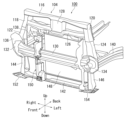
図1は、本発明の実施例に係る車体前部構造100が適用された車両102を斜め前方から見た状態を示す図である。なお以下各図において、車両前後方向をそれぞれ矢印Front、Back、車幅方向の左右をそれぞれ矢印Left、Right、車両上下方向をそれぞれ矢印Up、Downで例示する。
FIG. 1 is a diagram showing a
車両102の前部には、パワーユニット搭載ルーム104を上から覆うフロントフード106が配置されている。車両102は、小型車などであり、そのパワーユニット搭載ルーム104は省スペース化が図られている。このため、パワーユニット搭載ルーム104では、車両前後方向に長いスペースを確保することが困難である。
A
本実施例では、このような狭小なパワーユニット搭載ルーム104を備えた車両102において、図示を省略する障害物(歩行者)がフロントバンパ108に衝突した場合に障害物(歩行者)を保護するための、車体前部構造100を採用した。
In this embodiment, in the
フロントバンパ108は、車体前端に設置され車幅方向に延びる長尺で薄板状の部材である。フロントバンパ108は、ラジエータアッパグリル110、ラジエータロアグリル112およびフロントロアバンパ114を有する。
The
図2は、図1の車体前部構造100の要部を示す図である。ここでは、図1の車両102からフロントフード106およびフロントバンパ108などを省略し、車体前部構造100とともに車体骨格も示している。なお車体骨格は、複数の車体構造部材が接合されることにより形成されている。ただし図2に示す車体骨格については、理解を容易にするための例示にすぎず、これに限定するものではない。
FIG. 2 is a diagram showing a main part of the vehicle
車体骨格において、車幅方向の上方の骨格はフードロックメンバ116によって構成されている。このフードロックメンバ116の車幅方向の両端には、上下方向に延びる一対のランプサポートブレース118、120が接合されている。ランプサポートブレース118、120の下方には、上下方向に延びる一対のエプロンサイドメンバエクステンション122、124が接合されている。また、フードロックメンバ116の下方には、車幅方向に延びるラジエータサポートメンバ126が配置されている。フードロックメンバ116とラジエータサポートメンバ126は、車幅方向中央でフードロックリンフォース128によって接合されている。
In the vehicle body frame, the upper frame in the vehicle width direction is constituted by a
また、ラジエータサポートメンバ126の下方には、車幅方向に延びるバンパメンバ130が配置されている。バンパメンバ130の車幅方向の両端には、一対のバンパメンバリンフォース132、134が接合されている。なおバンパメンバリンフォース132には、バンパメンバプレート136が接合されている。さらに、バンパメンバ130の車幅方向の両端の後側には、車両前後方向に延びる一対のエプロンサイドメンバ138、140が配置されている。一対のエプロンサイドメンバ138、140とフードロックメンバ116の車幅方向の両端とは、上下方向に延びる一対のランプサポートブレース118、120およびエプロンサイドメンバエクステンション122、124によって接合されている。
A
さらにバンパメンバ130の下方には、車幅方向の下方の骨格として車幅方向に延びるロアクロスメンバ142が配置されている。ロアクロスメンバ142の車幅方向の両端とバンパメンバ130の車幅方向の両端とは、車両上下方向に延びる一対のロアエプロンサイドメンバエクステンション144、146によって接合されている。図1に示す小型車である車両102では、これらの各部材により、車体骨格が形成され、パワーユニット搭載ルーム104が区画されている。
Further, a
この車両102に適用される車体前部構造100は、車体構造部材であるバンパメンバ130およびロアクロスメンバ142を備える。車体前部構造100はさらに、上記フロントバンパ108と、フロントバンパ108の後側に配置されたラジエータ148と、シュラウド150と、一対のリンフォース152、154とを備える。
A vehicle
バンパメンバ130は、図示のようにラジエータ148とシュラウド150の間に配置されていて、シュラウド150の後側に位置する剛性の高い部材である。バンパメンバ130の高さは、障害物(歩行者)の膝の高さに等しい場合がある。ロアクロスメンバ142は、ラジエータ148の下方に配置されていて、車幅方向に延びている剛性の高い部材である。
シュラウド150は、図示のようにフロントバンパ108とラジエータ148との間で上下方向に延びていて、フロントバンパ108を通過する外気をラジエータに導く。一対のリンフォース152、154は、ロアクロスメンバ142の車幅方向の両端に接合されている。
The
図3は、図2の車体前部構造100のシュラウド150を拡大して示す図である。シュラウド150は、上下方向に延びる柱状の部材であり、第1バンパ固定部156、158(図4参照)と、第2バンパ固定部160、162と、第3バンパ固定部164とを有し、これらはフロントバンパ108の後側に固定される。
FIG. 3 is an enlarged view of the
第1バンパ固定部156、158は、シュラウド150の下端部166に形成されている。この下端部166は、図示のように車両後方に開放されたくぼみ形状を有する。第1バンパ固定部156、158は、フロントバンパ108のラジエータロアグリル112(図1参照)に固定され、例えば障害物(歩行者)の脚部の高さに位置している。
First
第2バンパ固定部160、162は、第1バンパ固定部156、158の上方でラジエータロアグリル112に固定され、例えば障害物(歩行者)の膝の高さに位置している。また第1バンパ固定部156、158と第2バンパ固定部160、162は、下側部位168によってつながれている。
The second
シュラウド150では、第2バンパ固定部160、162が第1バンパ固定部156、158よりも前方に位置し、下側部位168が第2バンパ固定部160、162よりも後方に位置している。このため、フロントバンパ108に障害物(歩行者)が衝突した場合、第2バンパ固定部160、162は、第1バンパ固定部156、158に先行して荷重を受けることになる。
In
第3バンパ固定部164は、シュラウド150の上端部170に形成されている。第3バンパ固定部164は、第2バンパ固定部160、162の上方でラジエータアッパグリル110に固定される。また第3バンパ固定部164と第2バンパ固定部160、162は、上側部位172によってつながれている。
The third
図4は、図3のシュラウド150の要部を示す図である。図4(a)、図4(b)は、シュラウド150の下端部166を斜め前方、斜め後方から見た状態をそれぞれ示す図である。図4(c)は、シュラウド150の第2バンパ固定部160、162および周辺を斜め後方から見た状態を示す図である。
FIG. 4 is a diagram showing the essential parts of
シュラウド150の下端部166は、図4(a)および図4(b)に示すように、上記第1バンパ固定部156、158と、底部174と、連結部176、178とを有する。第1バンパ固定部156、158は、くぼみ形状の下端部166の前面180に形成された係合孔であって、ラジエータロアグリル112の爪部182、184(図6(b)参照)と係合してラジエータロアグリル112に固定される。
The
底部174は、第1バンパ固定部156、158が形成された前面180の下端186から連続して後方に延びる部位であり、図4(b)に示すように後方にゆくほど車幅方向に広がる末広がり形状を有する。このため、底部174の後端187は、底部174のうち車幅方向の寸法が最も大きい部位となっている。
The
連結部176、178は、第1バンパ固定部156、158と底部174とをつなぐ部位である。具体的には、連結部176は、第1バンパ固定部156および底部174の車幅方向右側の一端同士をつなぐ側壁である。連結部178は、第1バンパ固定部158および底部174の車幅方向左側の一端同士をつなぐ側壁である。このような側壁である連結部176、178は、第1バンパ固定部156、158と底部174とをつなぐことにより、底部174の剛性を高めている。
The connecting
シュラウド150の下端部166はさらに、一対のビード188、190と、図4(b)に示すリブ192とを有する。一対のビード188、190は、図4(a)に示すように前面180に形成されていて、前側に凸状になっている。また、一対のビード188、190は、第1バンパ固定部156、158の周辺に位置し、L字状に形成されていて、側壁である連結部176、178まで延びている。このようにして、一対のビード188、190は、第1バンパ固定部156、158およびその周辺の剛性を高めている。
The
リブ192は、図4(b)に示すように、一対のビード188、190の間に位置し、底部174の前端すなわち前面180の下端186から第1バンパ固定部156、158に沿って上方に延びている。またリブ192は、底部174から上方に延びて、さらに底部174に対向する上面193まで延びて、底部174と上面193とをつないでいる。この上面193は、後方にゆくほど上方に傾斜している。このようにして、リブ192は、底部174の剛性を高めている。
4(b), the
図4(c)に示す第2バンパ固定部160、162は、後述するが、前後方向の位置が異なるように形成されていて、前後方向にオフセットしている(図7参照)。またシュラウド150はさらに、薄肉リブ194を有する。薄肉リブ194は、前後方向にオフセットした第2バンパ固定部160、162の間に沿って、下側部位168から上方に延びて、下側部位168と上側部位172とをつないでいる。また薄肉リブ194は、図4(c)に示すように、下側部位168から上側部位172まで上方に延びつつ、第2バンパ固定部160、162の後方に位置する部位196が、他の部位198よりも前後方向に短くなっている。
As will be described later, the second
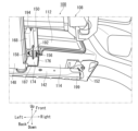
図5は、図1の車体前部構造100のA-A断面図である。シュラウド150の下端部166では、図示のように、底部174の後端187および連結部176が、ロアクロスメンバ142の前方に位置していて、さらにロアクロスメンバ142と高さが等しくなっている。すなわち、シュラウド150の後端187と連結部176の一部または全部は、これらの部位が位置する箇所で、ロアクロスメンバ142の上下方向の範囲内に位置している。また、シュラウド150の底部174は、後方にゆくほど下方に傾斜している。なお連結部178も同様に、ロアクロスメンバ142の前方に位置し、ロアクロスメンバ142と高さが等しい。
FIG. 5 is a cross-sectional view of the vehicle
ここで、フロントバンパ108のラジエータロアグリル112やフロントロアバンパ114に障害物(歩行者)の脚部が衝突した場合、シュラウド150の下端部166では、フロントバンパ108からシュラウド150の第1バンパ固定部156、158に荷重が伝達される。つぎに、シュラウド150の下端部166では、この荷重を受けて、底部174の後端187および連結部176、178が図5の矢印Bに示すように後退し、さらに点線Cに示すようにロアクロスメンバ142に当接する。また、シュラウド150の底部174が後方にゆくほど下方に傾斜しているため、衝突時に底部174の後端187および連結部176、178をロアクロスメンバ142に確実に当接させることができる。
Here, when the legs of an obstacle (pedestrian) collide with radiator
つまり車体前部構造100では、衝突時に、剛性の高いロアクロスメンバ142が後ろ盾になって、シュラウド150の後退が抑制されるため、フロントバンパ108が後退し難くなり、障害物(歩行者)の脚部を上方に確実に跳ね上げて保護できる。
In other words, in the vehicle
また車体前部構造100では、シュラウド150の底部174が、末広がり形状であるため、底部174の後端187すなわち衝突時にロアクロスメンバ142と当接する部位の車幅方向の寸法を大きくできる。このため、シュラウド150は、衝突時の荷重をロアクロスメンバ142に確実に分散させて、フロントバンパ108が後方に後退することを確実に防止できる。さらに、底部174の後端187の車幅方向の寸法を大きくできるため、シュラウド150が衝突時に上下方向の軸に対して回転してねじれ変形することも防止できる。
In the vehicle
シュラウド150では、第1バンパ固定部156、158と底部174を連結部176、178によってつなぐことにより、底部174の剛性を高めて、衝突時に底部174が折れて変形することを防止している。またシュラウド150は、底部174がリブ192によっても補強されているため、衝突時に底部174が折れることをさらに防止できる。すなわちシュラウド150によれば、衝突時に底部174が折れて変形し荷重が吸収され、障害物(歩行者)の脚部を十分に跳ね上げることができず、脚部を保護することが困難になる、という事態を回避できる。
In the
また車体前部構造100では、シュラウド150を設置するための車両前後方向のスペースが、図5に示すシュラウド150の底部174の車両前後方向のスペース、すなわち前面180の下端186から底部174の後端187までのスペースだけで済む。したがって車体前部構造100は、車両前後方向に長いスペースを確保できない狭小なパワーユニット搭載ルーム104を備えた小型車などの車両102(図1参照)にも適用可能である。
In the vehicle
図6は、図3のシュラウド150の要部をフロントバンパ108とともに示す図である。図6(a)は、シュラウド150およびフロントバンパ108を斜め後方から見た状態を示す図である。図6(b)は、図6(a)の車体前部構造100のD-D断面図である。
FIG. 6 is a diagram showing a main portion of the
シュラウド150の第1バンパ固定部156、158および第2バンパ固定部160、162は、図6(a)に示すように、フロントバンパ108のラジエータロアグリル112に固定されている。特に第1バンパ固定部156、158は、図6(b)に示すように、ラジエータロアグリル112から後方に突出した爪部182、184が係合孔に挿入されることで、爪部182、184と係合してラジエータロアグリル112に固定されている。
The first
また、第1バンパ固定部156、158の周辺に形成された前側に凸状の一対のビード188、190は、前方のラジエータロアグリル112に対向している。このため、フロントバンパ108に障害物(歩行者)の脚部が衝突した場合、後退するラジエータロアグリル112に対して、第1バンパ固定部156、158およびその周辺が突っ張って変形し難くなる。したがって車体前部構造100では、障害物(歩行者)の脚部を確実に跳ね上げることができ、脚部の保護性能を向上させることができる。
Also, a pair of forwardly projecting
図7は、図3のシュラウド150の第2バンパ固定部160、162およびその周辺構造を示す図である。図7(a)は、シュラウド150を斜め前方から見た状態を示している。また図7(a)では、シュラウド150の前方に位置するフロントバンパ108と、シュラウド150の後方に位置するバンパメンバ130とを点線で示している。図7(b)は、シュラウド150の第2バンパ固定部160、162およびその周辺構造を上方から見た状態を示し、さらにフロントバンパ108の一部の断面を示している。
FIG. 7 is a diagram showing the second
図7(a)に示すバンパメンバ130は、シュラウド150の後側に位置する剛性の高い部材であって、その高さは障害物(歩行者)の膝の高さに等しい場合がある。そこでシュラウド150では、図7(a)および図7(b)に示すようにバンパメンバ130と等しい高さに、前後方向の位置が異なるすなわち前後方向にオフセットした第2バンパ固定部160、162を設けている。
The
このため、フロントバンパ108に障害物(歩行者)の膝が衝突した場合、まず、第2バンパ固定部160、162のうち、最も前方に位置する第2バンパ固定部160に荷重が伝達される。第2バンパ固定部160は、図7(b)に示すように第2バンパ固定部162よりも前方にオフセットしている分、荷重を受けたときに確実に後退することができる。
Therefore, when the knee of an obstacle (pedestrian) collides with the
すなわち車体前部構造100では、最も前方に位置する第2バンパ固定部160に対して、衝突時に後退するための前後方向のストロークを確保することができる。このため、第2バンパ固定部160は、荷重を受けると確実に後退して荷重を吸収できる。また図4(c)に示す薄肉リブ194は、第2バンパ固定部160、162の後方に位置する部位196が、他の部位198よりも前後方向に短くなっているため、荷重を受けると変形し易い脆弱なものである。
That is, in the vehicle
このためシュラウド150は、衝突時に第2バンパ固定部160、162および薄肉リブ194の周辺において、バンパメンバ130の車両前方で上下方向の軸に対して回転して左右に折れるようにねじれ変形し、さらに後退しながら荷重を吸収できる。したがって車体前部構造100では、バンパメンバ130の周辺の衝撃吸収性能を高めることができ、障害物(歩行者)の膝を保護できる。また上記したように、第2バンパ固定部160、162は、第1バンパ固定部156、158に先行して荷重を受けるため、ねじれ変形し易くなる。なおここでは、シュラウド150に前後方向にオフセットした2つの第2バンパ固定部160、162を設けたが、これに限定されず、バンパメンバ130の車両前方でねじれ変形を生じさせることが可能であれば、3つ以上の第2バンパ固定部を適宜設けてもよい。
Therefore, the
図8は、図2の車体前部構造100の一部をフロントバンパ108とともに示す図である。リンフォース152は、図示のように、ロアクロスメンバ142の車幅方向右側の端部199と、フロントバンパ108のフロントロアバンパ114との間に配置され、これら端部199とフロントロアバンパ114を連結している。なお図2に示すリンフォース154は、図示を省略するが、ロアクロスメンバ142の車幅方向左側の端部とフロントロアバンパ114を連結している。
FIG. 8 is a diagram showing a portion of the vehicle
このため、フロントバンパ108に障害物(歩行者)の脚部が衝突した場合、フロントバンパ108が受けた荷重は、一対のリンフォース152、154を介してロアクロスメンバ142の車幅方向の両端まで伝達し分散される。したがって車体前部構造100では、フロントバンパ108が車幅方向の両端で後退することを抑制し、障害物(歩行者)の脚部保護性能を高めることができる。
Therefore, when the legs of an obstacle (pedestrian) collide with the
以上、添付図面を参照しながら本発明の好適な実施例について説明したが、本発明はかかる例に限定されないことは言うまでもない。当業者であれば、特許請求の範囲に記載された範疇内において、各種の変更例または修正例に想到し得ることは明らかであり、それらについても当然に本発明の技術的範囲に属するものと了解される。 Although the preferred embodiments of the present invention have been described above with reference to the accompanying drawings, it goes without saying that the present invention is not limited to such examples. It is obvious that a person skilled in the art can conceive of various modifications or modifications within the scope described in the claims, and these also belong to the technical scope of the present invention. Understood.
本発明は、車体前部構造に利用することができる。 INDUSTRIAL APPLICABILITY The present invention can be used for a vehicle body front structure.
100…車体前部構造、102…車両、104…パワーユニット搭載ルーム、106…フロントフード、108…フロントバンパ、110…ラジエータアッパグリル、112…ラジエータロアグリル、114…フロントロアバンパ、116…フードロックメンバ、118、120…ランプサポートブレース、122、124…エプロンサイドメンバエクステンション、126…ラジエータサポートメンバ、128…フードロックリンフォース、130…バンパメンバ、132、134…バンパメンバリンフォース、136…バンパメンバプレート、138、140…エプロンサイドメンバ、142…ロアクロスメンバ、144、146…ロアエプロンサイドメンバエクステンション、148…ラジエータ、150…シュラウド、152、154…リンフォース、156、158…第1バンパ固定部、160、162…第2バンパ固定部、164…第3バンパ固定部、166…シュラウドの下端部、168…下側部位、170…シュラウドの上端部、172…上側部位、174…底部、176、178…連結部、180…前面、182、184…爪部、186…前面の下端、187…底部の後端、188、190…ビード、192…リブ、193…上面、194…薄肉リブ、196、198…薄肉リブの部位、199…ロアクロスメンバの端部
DESCRIPTION OF
Claims (7)
車幅方向に延びてラジエータの下方に配置されるロアクロスメンバと、
上下方向に延びて前記フロントバンパを通過する外気を前記ラジエータに導くシュラウドとを備え、
前記シュラウドは、前記ロアクロスメンバの前方に位置して前記フロントバンパの後側に固定されるバンパ固定部を有することを特徴とする車体前部構造。 a vehicle front bumper;
a lower cross member extending in the vehicle width direction and arranged below the radiator ;
a shroud that extends vertically and guides outside air passing through the front bumper to the radiator;
The vehicle body front structure, wherein the shroud has a bumper fixing portion positioned in front of the lower cross member and fixed to the rear side of the front bumper.
前記シュラウドは、前記バンパメンバの前方に位置して前記フロントバンパの後側に固定される複数の第2バンパ固定部を有し、
前記複数の第2バンパ固定部は、前後方向の位置が互いに異なる少なくとも2つの第2バンパ固定部を含むことを特徴とする請求項1から5のいずれか1項に記載の車体前部構造。 The vehicle body front structure includes a bumper member disposed between the shroud and the radiator and above the bumper fixing portion and extending in the vehicle width direction,
The shroud has a plurality of second bumper fixing portions positioned in front of the bumper member and fixed to the rear side of the front bumper,
The vehicle body front structure according to any one of claims 1 to 5 , wherein the plurality of second bumper fixing portions includes at least two second bumper fixing portions whose positions in the front-rear direction are different from each other. .
Priority Applications (1)
| Application Number | Priority Date | Filing Date | Title |
|---|---|---|---|
| JP2020030447A JP7322750B2 (en) | 2020-02-26 | 2020-02-26 | Body front structure |
Applications Claiming Priority (1)
| Application Number | Priority Date | Filing Date | Title |
|---|---|---|---|
| JP2020030447A JP7322750B2 (en) | 2020-02-26 | 2020-02-26 | Body front structure |
Publications (3)
| Publication Number | Publication Date |
|---|---|
| JP2021133773A JP2021133773A (en) | 2021-09-13 |
| JP2021133773A5 JP2021133773A5 (en) | 2022-12-02 |
| JP7322750B2 true JP7322750B2 (en) | 2023-08-08 |
Family
ID=77659942
Family Applications (1)
| Application Number | Title | Priority Date | Filing Date |
|---|---|---|---|
| JP2020030447A Active JP7322750B2 (en) | 2020-02-26 | 2020-02-26 | Body front structure |
Country Status (1)
| Country | Link |
|---|---|
| JP (1) | JP7322750B2 (en) |
Citations (4)
| Publication number | Priority date | Publication date | Assignee | Title |
|---|---|---|---|---|
| JP4972942B2 (en) | 2006-01-31 | 2012-07-11 | マツダ株式会社 | Automotive front structure |
| JP2014511295A (en) | 2010-11-17 | 2014-05-15 | ルノー エス.ア.エス. | Cooling device having an air guide for a radiator of an automobile engine |
| JP2015182480A (en) | 2014-03-20 | 2015-10-22 | スズキ株式会社 | Air stream guide plate |
| JP2017144814A (en) | 2016-02-16 | 2017-08-24 | マツダ株式会社 | Vehicular bumper structure |
-
2020
- 2020-02-26 JP JP2020030447A patent/JP7322750B2/en active Active
Patent Citations (4)
| Publication number | Priority date | Publication date | Assignee | Title |
|---|---|---|---|---|
| JP4972942B2 (en) | 2006-01-31 | 2012-07-11 | マツダ株式会社 | Automotive front structure |
| JP2014511295A (en) | 2010-11-17 | 2014-05-15 | ルノー エス.ア.エス. | Cooling device having an air guide for a radiator of an automobile engine |
| JP2015182480A (en) | 2014-03-20 | 2015-10-22 | スズキ株式会社 | Air stream guide plate |
| JP2017144814A (en) | 2016-02-16 | 2017-08-24 | マツダ株式会社 | Vehicular bumper structure |
Also Published As
| Publication number | Publication date |
|---|---|
| JP2021133773A (en) | 2021-09-13 |
Similar Documents
| Publication | Publication Date | Title |
|---|---|---|
| JP4797726B2 (en) | Automotive front structure | |
| JP4872541B2 (en) | Automotive bumper structure | |
| JP5761212B2 (en) | Vehicle hood structure | |
| JP5969417B2 (en) | Body front structure | |
| JP4479550B2 (en) | Engine under cover mounting structure | |
| JP5994321B2 (en) | Body front structure | |
| JP4781171B2 (en) | Fender panel mounting structure for vehicles | |
| WO2012096244A1 (en) | Structure for front hood of automobile | |
| JP6601439B2 (en) | Vehicle front hood | |
| JP4894270B2 (en) | Front body structure of automobile | |
| JP2010000866A5 (en) | ||
| JP2005178682A (en) | Body front structure of automobile | |
| JP4876822B2 (en) | Rear bumper structure of automobile | |
| JP7322750B2 (en) | Body front structure | |
| JP2011079471A (en) | Mounting structure for battery | |
| JP4798485B2 (en) | Vehicle front bumper structure | |
| JP7052332B2 (en) | Vehicle front structure | |
| KR20200117277A (en) | Front pillar structure for vehicle | |
| JP7351817B2 (en) | car body | |
| JP2011246040A (en) | Pedestrian protecting device for vehicle | |
| JP6024429B2 (en) | Automobile leg mounting structure | |
| JP5577214B2 (en) | Auto body front structure | |
| JP5966895B2 (en) | Automobile leg mounting structure | |
| JP5880414B2 (en) | Automobile leg mounting structure | |
| JP2008143233A (en) | Vehicle front body structure |
Legal Events
| Date | Code | Title | Description |
|---|---|---|---|
| A521 | Request for written amendment filed |
Free format text: JAPANESE INTERMEDIATE CODE: A523 Effective date: 20221124 |
|
| A621 | Written request for application examination |
Free format text: JAPANESE INTERMEDIATE CODE: A621 Effective date: 20221201 |
|
| A977 | Report on retrieval |
Free format text: JAPANESE INTERMEDIATE CODE: A971007 Effective date: 20230613 |
|
| TRDD | Decision of grant or rejection written | ||
| A01 | Written decision to grant a patent or to grant a registration (utility model) |
Free format text: JAPANESE INTERMEDIATE CODE: A01 Effective date: 20230627 |
|
| A61 | First payment of annual fees (during grant procedure) |
Free format text: JAPANESE INTERMEDIATE CODE: A61 Effective date: 20230710 |
|
| R151 | Written notification of patent or utility model registration |
Ref document number: 7322750 Country of ref document: JP Free format text: JAPANESE INTERMEDIATE CODE: R151 |