JP5975199B1 - Steering device - Google Patents
Steering device Download PDFInfo
- Publication number
- JP5975199B1 JP5975199B1 JP2016530024A JP2016530024A JP5975199B1 JP 5975199 B1 JP5975199 B1 JP 5975199B1 JP 2016530024 A JP2016530024 A JP 2016530024A JP 2016530024 A JP2016530024 A JP 2016530024A JP 5975199 B1 JP5975199 B1 JP 5975199B1
- Authority
- JP
- Japan
- Prior art keywords
- pair
- stopper
- column
- steering
- portions
- Prior art date
- Legal status (The legal status is an assumption and is not a legal conclusion. Google has not performed a legal analysis and makes no representation as to the accuracy of the status listed.)
- Active
Links
- 230000002093 peripheral effect Effects 0.000 claims description 32
- 230000008602 contraction Effects 0.000 claims description 21
- 238000006073 displacement reaction Methods 0.000 claims description 9
- 230000001105 regulatory effect Effects 0.000 claims description 3
- 230000035939 shock Effects 0.000 description 5
- XEEYBQQBJWHFJM-UHFFFAOYSA-N Iron Chemical compound [Fe] XEEYBQQBJWHFJM-UHFFFAOYSA-N 0.000 description 4
- 229910045601 alloy Inorganic materials 0.000 description 4
- 239000000956 alloy Substances 0.000 description 4
- 229920003002 synthetic resin Polymers 0.000 description 4
- 239000000057 synthetic resin Substances 0.000 description 4
- 229910052751 metal Inorganic materials 0.000 description 3
- 239000002184 metal Substances 0.000 description 3
- 229910052782 aluminium Inorganic materials 0.000 description 2
- XAGFODPZIPBFFR-UHFFFAOYSA-N aluminium Chemical compound [Al] XAGFODPZIPBFFR-UHFFFAOYSA-N 0.000 description 2
- 230000005540 biological transmission Effects 0.000 description 2
- 239000003638 chemical reducing agent Substances 0.000 description 2
- 229910052742 iron Inorganic materials 0.000 description 2
- 239000000463 material Substances 0.000 description 2
- 238000005096 rolling process Methods 0.000 description 2
- 238000000034 method Methods 0.000 description 1
- 229920005989 resin Polymers 0.000 description 1
- 239000011347 resin Substances 0.000 description 1
- 125000006850 spacer group Chemical group 0.000 description 1
- 239000000725 suspension Substances 0.000 description 1
Images


Classifications
-
- B—PERFORMING OPERATIONS; TRANSPORTING
- B62—LAND VEHICLES FOR TRAVELLING OTHERWISE THAN ON RAILS
- B62D—MOTOR VEHICLES; TRAILERS
- B62D1/00—Steering controls, i.e. means for initiating a change of direction of the vehicle
- B62D1/02—Steering controls, i.e. means for initiating a change of direction of the vehicle vehicle-mounted
- B62D1/16—Steering columns
- B62D1/18—Steering columns yieldable or adjustable, e.g. tiltable
- B62D1/19—Steering columns yieldable or adjustable, e.g. tiltable incorporating energy-absorbing arrangements, e.g. by being yieldable or collapsible
- B62D1/192—Yieldable or collapsible columns
-
- B—PERFORMING OPERATIONS; TRANSPORTING
- B62—LAND VEHICLES FOR TRAVELLING OTHERWISE THAN ON RAILS
- B62D—MOTOR VEHICLES; TRAILERS
- B62D1/00—Steering controls, i.e. means for initiating a change of direction of the vehicle
- B62D1/02—Steering controls, i.e. means for initiating a change of direction of the vehicle vehicle-mounted
- B62D1/16—Steering columns
- B62D1/18—Steering columns yieldable or adjustable, e.g. tiltable
- B62D1/19—Steering columns yieldable or adjustable, e.g. tiltable incorporating energy-absorbing arrangements, e.g. by being yieldable or collapsible
- B62D1/195—Yieldable supports for the steering column
-
- B—PERFORMING OPERATIONS; TRANSPORTING
- B62—LAND VEHICLES FOR TRAVELLING OTHERWISE THAN ON RAILS
- B62D—MOTOR VEHICLES; TRAILERS
- B62D1/00—Steering controls, i.e. means for initiating a change of direction of the vehicle
- B62D1/02—Steering controls, i.e. means for initiating a change of direction of the vehicle vehicle-mounted
- B62D1/16—Steering columns
- B62D1/18—Steering columns yieldable or adjustable, e.g. tiltable
- B62D1/184—Mechanisms for locking columns at selected positions
-
- B—PERFORMING OPERATIONS; TRANSPORTING
- B62—LAND VEHICLES FOR TRAVELLING OTHERWISE THAN ON RAILS
- B62D—MOTOR VEHICLES; TRAILERS
- B62D1/00—Steering controls, i.e. means for initiating a change of direction of the vehicle
- B62D1/02—Steering controls, i.e. means for initiating a change of direction of the vehicle vehicle-mounted
- B62D1/16—Steering columns
- B62D1/18—Steering columns yieldable or adjustable, e.g. tiltable
- B62D1/185—Steering columns yieldable or adjustable, e.g. tiltable adjustable by axial displacement, e.g. telescopically
-
- F—MECHANICAL ENGINEERING; LIGHTING; HEATING; WEAPONS; BLASTING
- F16—ENGINEERING ELEMENTS AND UNITS; GENERAL MEASURES FOR PRODUCING AND MAINTAINING EFFECTIVE FUNCTIONING OF MACHINES OR INSTALLATIONS; THERMAL INSULATION IN GENERAL
- F16H—GEARING
- F16H25/00—Gearings comprising primarily only cams, cam-followers and screw-and-nut mechanisms
- F16H25/08—Gearings comprising primarily only cams, cam-followers and screw-and-nut mechanisms for interconverting rotary motion and reciprocating motion
- F16H25/14—Gearings comprising primarily only cams, cam-followers and screw-and-nut mechanisms for interconverting rotary motion and reciprocating motion with reciprocation perpendicular to the axis of rotation
-
- B—PERFORMING OPERATIONS; TRANSPORTING
- B62—LAND VEHICLES FOR TRAVELLING OTHERWISE THAN ON RAILS
- B62D—MOTOR VEHICLES; TRAILERS
- B62D1/00—Steering controls, i.e. means for initiating a change of direction of the vehicle
- B62D1/02—Steering controls, i.e. means for initiating a change of direction of the vehicle vehicle-mounted
- B62D1/16—Steering columns
- B62D1/18—Steering columns yieldable or adjustable, e.g. tiltable
- B62D1/187—Steering columns yieldable or adjustable, e.g. tiltable with tilt adjustment; with tilt and axial adjustment
- B62D1/189—Steering columns yieldable or adjustable, e.g. tiltable with tilt adjustment; with tilt and axial adjustment the entire column being tiltable as a unit
Landscapes
- Engineering & Computer Science (AREA)
- Mechanical Engineering (AREA)
- Chemical & Material Sciences (AREA)
- Combustion & Propulsion (AREA)
- Transportation (AREA)
- General Engineering & Computer Science (AREA)
- Steering Controls (AREA)
Abstract
ステアリングホイールの前後位置を調節する際に、このステアリングホイールを前端位置まで勢いよく変位させた場合でも、支持ブラケットに前方に向いた衝撃が加わることを防止できるステアリング装置の構造を実現する。ストッパ部材28の一部が、ハウジング10aなどの固定部材に支持される。ステアリングホイールの前後位置を調節可能にした状態で、アウタコラム22aが前方に変位した場合に、調節ロッドと1対のテレスコ調節用長孔とが衝突する以前に、アウタコラム22aとともに前方に変位する部分が、ストッパ部材28の1対のストッパ面41に衝突する。When adjusting the front-rear position of the steering wheel, the structure of the steering device is realized that can prevent a forward impact from being applied to the support bracket even when the steering wheel is displaced to the front end position. A part of the stopper member 28 is supported by a fixing member such as the housing 10a. When the outer column 22a is displaced forward with the front / rear position of the steering wheel being adjustable, it is displaced forward together with the outer column 22a before the adjustment rod and the pair of telescopic adjustment long holes collide with each other. The portion collides with a pair of stopper surfaces 41 of the stopper member 28.
Description
本発明は、ステアリングホイールの前後位置の調節を可能とし、かつ、二次衝突時に、ステアリングコラムを前方への離脱を可能に車体に支持するための構造を備えたステアリング装置に関する。 The present invention relates to a steering apparatus having a structure for supporting a steering column on a vehicle body so that the front and rear positions of a steering wheel can be adjusted and a steering column can be detached forward during a secondary collision.
図10は、従来構造の自動車用ステアリング装置を示している。ステアリングホイール1の回転はステアリングギヤユニット2の入力軸3に伝達され、入力軸3の回転に伴って左右1対のタイロッド4が押し引きされて、前車輪に舵角が付与される。ステアリングホイール1は、ステアリングシャフト5の後端部に支持固定されており、ステアリングシャフト5は、円筒状のステアリングコラム6を軸方向に挿通した状態で、ステアリングコラム6に回転自在に支持されている。ステアリングシャフト5の前端部は、自在継手7を介して中間シャフト8の後端部に接続され、中間シャフト8の前端部は、別の自在継手9を介して、入力軸3に接続されている。ステアリングコラム6の前端部は、電動式パワーステアリング装置を構成する減速機やトルク測定器などの部品が収納されたハウジング10の後端部に結合固定されている。ハウジング10には、電動式パワーステアリング装置の動力源である電動モータ11が支持されている。なお、前後方向、左右方向(幅方向)、および上下方向は、特に断らない限り、車両の前後方向、左右方向(幅方向)、および上下方向を意味する。
FIG. 10 shows an automotive steering apparatus having a conventional structure. The rotation of the steering wheel 1 is transmitted to the input shaft 3 of the
特開2012−86588号公報、特開2013−18472号公報などに開示されているように、ステアリング装置には、運転者の体格や運転姿勢などに応じて、ステアリングホイール1の上下位置を調節するためのチルト機構や、ステアリングホイール1の前後位置を調節するためのテレスコピック機構が組み込まれる。チルト機構は、ステアリングコラム6の前端部が車体に対し、幅方向に配置されたチルト用枢軸12により、揺動変位を可能に支持されることにより構成される。ステアリングコラム6の中間部後端寄り部分に被挟持部13が固設されており、被挟持部13が、車体14に組み付けられた支持ブラケット15の左右1対の支持板部16同士の間に挟持されている。1対の支持板部16の互いに整合する部分には、上下方向に伸長するチルト調節用長孔18が形成されている。調節ロッド17が、被挟持部13のチルト調節用長孔18に挿通されている。ステアリングホイール1の上下位置は、調節ロッド17がチルト調節用長孔18内で変位できる範囲内で、調節可能である。
As disclosed in JP 2012-86588 A, JP 2013-18472 A, and the like, the steering device adjusts the vertical position of the steering wheel 1 according to the physique and driving posture of the driver. And a telescopic mechanism for adjusting the front-rear position of the steering wheel 1 are incorporated. The tilt mechanism is configured such that the front end portion of the steering column 6 is supported by the
テレスコピック機構は、ステアリングシャフト5およびステアリングコラム6を伸縮可能とすることにより構成される。ステアリングシャフト5は、前側のインナシャフト19の後端部と後側のアウタシャフト20の前端部とを、スプライン係合などの非円形嵌合により、トルクの伝達を可能に、かつ、軸方向の変位を可能に組み合わせた構造を有している。ステアリングコラム6は、前側のインナコラム21の後端部と後側のアウタコラム22の前端部と嵌合させることにより、前後方向の変位を可能に組み合わせた構造を有している。被挟持部13には、ステアリングコラム6の軸方向に伸長するテレスコ調節用長孔23が形成されている。調節ロッド17は、テレスコ調節用長孔23にも挿通されている。ステアリングホイール1の前後位置は、調節ロッド17がテレスコ調節用長孔23内で変位できる範囲内で、調節可能である。
The telescopic mechanism is configured by allowing the
調節ロッド17の軸方向両端部のうち、1対の支持板部16の外側面から突出した部分には、1対の押圧部が設けられており、調節ロッド17の軸方向一端部には、調節レバーが設けられている。1対の押圧部同士の間隔は、この調節レバーの操作に基づいて作動する拡縮装置により、拡縮可能になっている。
A pair of pressing portions is provided at portions protruding from the outer side surfaces of the pair of
ステアリングホイール1の上下位置または前後位置を調節する際には、調節レバーを所定方向(一般的には下方)に揺動させることにより、1対の押圧部同士の間隔を拡げ、1対の支持板部16の内側面と被挟持部13の外側面との間に作用している摩擦力を小さくする。この摩擦力を小さくした状態で、調節ロッド17が、チルト調節用長孔18およびテレスコ調節用長孔23内で変位できる範囲で、ステアリングホイール1の位置が調節可能となる。調節後は、調節レバーを所定方向とは逆方向(一般的には上方)に揺動させることにより、1対の押圧部同士の間隔を縮め、前記摩擦力を大きくすることにより、ステアリングホイール1が調節後の位置に保持される。
When adjusting the vertical position or the front / rear position of the steering wheel 1, the adjustment lever is swung in a predetermined direction (generally downward) to widen the distance between the pair of pressing portions and to support the pair. The frictional force acting between the inner surface of the
ステアリング装置には、衝突事故の際に、運転者の身体がステアリングホイール1に衝突する二次衝突が発生した場合に、運転者に加わる衝撃荷重を緩和するために、ステアリングホイール1が前方に変位することを許容する衝撃吸収機構も備えられている。この衝撃吸収機構は、支持ブラケット15を車体14に対し、二次衝突時の衝撃により前方への離脱を可能に支持することにより構成される。
In the steering device, in the event of a collision, when a secondary collision occurs in which the driver's body collides with the steering wheel 1, the steering wheel 1 is displaced forward to reduce the impact load applied to the driver. An impact absorbing mechanism is also provided to allow this. This shock absorbing mechanism is configured by supporting the
テレスコピック機構と衝撃吸収機構を備えたステアリング装置の場合、ステアリングホイール1の前後位置の調節を行う際に、ステアリングホイール1を最前位置にまで勢いよく変位させ、調節ロッド17の外周面にテレスコ調節用長孔23の後端部を勢いよく衝突させると、支持ブラケット15には、調節ロッド17を介して二次衝突時に加わる衝撃と同じ方向の衝撃が加わる。
In the case of a steering device equipped with a telescopic mechanism and an impact absorbing mechanism, when adjusting the front / rear position of the steering wheel 1, the steering wheel 1 is vigorously displaced to the foremost position, and the
二次衝突時に運転者に加わる衝撃荷重をより緩和できるようにするためには、車体14に対する支持ブラケット15の支持強度を小さくすることが考えられる。しかしながら、この支持強度を単に小さくすると、ステアリングホイール1の前後位置の調節を行う際に、ステアリングホイール1を前端位置まで勢いよく変位させると、支持ブラケット15に加わる衝撃によって、支持ブラケット15を車体に対して支持する部分にがたつきが発生し、ステアリングホイール1を操作する運転者に違和感を与える可能性がある。したがって、二次衝突時の衝撃荷重を緩和するとともに、支持ブラケット15の支持部分にがたつきが発生することを防止するために、ステアリングホイール1の前後位置を調節する際に、ステアリングホイール1を前端位置まで勢いよく変位させた場合でも、支持ブラケット15に前方に向いた衝撃が加わることを防止できるステアリング装置の構造の実現が望まれている。
In order to further reduce the impact load applied to the driver during the secondary collision, it is conceivable to reduce the support strength of the
本発明は、上述のような事情に鑑みて、ステアリングホイールの前後位置を調節する際に、ステアリングホイールを前端位置まで勢いよく変位させた場合でも、支持ブラケットに前方に向いた衝撃が加わることを防止できる、ステアリング装置を提供することを目的としている。 In the present invention, in view of the above situation, when adjusting the front / rear position of the steering wheel, even if the steering wheel is vigorously displaced to the front end position, a shock applied to the support bracket is applied to the support bracket. An object of the present invention is to provide a steering device that can be prevented.
本発明のステアリング装置は、ステアリングコラムと、1対の被挟持部と、1対のテレスコ調節用長孔と、支持ブラケットと、1対の車体側通孔と、調節ロッドと、1対の押圧部と、拡縮装置と、カム部材と、固定部材と、ストッパ部材とを備える。 The steering device of the present invention includes a steering column, a pair of clamped portions, a pair of telescopic adjustment long holes, a support bracket, a pair of vehicle body side through holes, an adjustment rod, and a pair of pressing members. A part, an expansion / contraction device, a cam member, a fixing member, and a stopper member.
前記ステアリングコラムは、インナコラムとアウタコラムとを有し、該インナコラムの後部と該アウタコラムの前部とを、軸方向の相対変位を可能に嵌合することにより構成される。該ステアリングコラムの内側には、伸縮可能なステアリングシャフトが回転自在に支持される。 The steering column includes an inner column and an outer column, and is configured by fitting a rear portion of the inner column and a front portion of the outer column so as to allow relative displacement in the axial direction. A telescopic steering shaft is rotatably supported inside the steering column.
前記1対の被挟持部は、前記アウタコラムの上面または下面の幅方向に離隔した2箇所位置に、該アウタコラムと一体に設けられている。 The pair of sandwiched portions are provided integrally with the outer column at two positions separated in the width direction of the upper surface or the lower surface of the outer column.
前記1対のテレスコ調節用長孔は、前記1対の被挟持部の互いに整合する部分に、前記アウタコラムの軸方向に伸長する状態で設けられている。 The pair of telescopic adjustment long holes are provided in a portion extending in the axial direction of the outer column in a portion where the pair of sandwiched portions are aligned with each other.
前記支持ブラケットは、前記1対の被挟持部を幅方向両側から挟む左右1対の支持板部を有し、車体に対し、二次衝突時に加わる荷重に基づいて前方への離脱を可能に支持されている。 The support bracket has a pair of left and right support plate portions that sandwich the pair of sandwiched portions from both sides in the width direction, and supports the vehicle body so that it can be detached forward based on a load applied during a secondary collision. Has been.
前記1対の車体側通孔は、前記1対の支持板部の互いに整合する部分に設けられている。 The pair of vehicle body side through holes are provided in portions of the pair of support plate portions that are aligned with each other.
前記調節ロッドは、前記1対の車体側通孔と前記1対のテレスコ調節用長孔とを幅方向に挿通する状態で設けられている。 The adjustment rod is provided in a state where the pair of vehicle body side through holes and the pair of telescopic adjustment long holes are inserted in the width direction.
前記1対の押圧部は、前記調節ロッドの両端部で、前記両支持板部の外側面から突出した部分に設けられている。 The pair of pressing portions are provided at portions projecting from the outer surfaces of the both support plate portions at both ends of the adjustment rod.
前記拡縮装置は、前記1対の押圧部同士の間隔を拡縮するためのものである。 The said expansion / contraction apparatus is for expanding / contracting the space | interval of said one pair of press parts.
前記カム部材は、前記調節ロッドのうち、該調節ロッドの軸方向中間部で前記1対の被挟持部同士の間に位置する部分に固定されている。 The cam member is fixed to a portion of the adjusting rod that is positioned between the pair of sandwiched portions at an intermediate portion in the axial direction of the adjusting rod.
前記固定部材は、前記車体に対する前後位置を規制された状態で設けられている。好ましくは、該固定部材は、前記インナコラムに固定される。 The fixing member is provided in a state in which a front-rear position with respect to the vehicle body is restricted. Preferably, the fixing member is fixed to the inner column.
前記ストッパ部材は、前記固定部材に支持された状態で後方に向いたストッパ面と、前記固定部材に支持された状態で前記ステアリングコラムの外周面と対向する上下方向片側面とを有し、該上下方向片側面を前記カム部材の外周面に当接させている。 The stopper member has a stopper surface facing rearward while being supported by the fixing member, and a vertical side surface facing the outer peripheral surface of the steering column while being supported by the fixing member, One side surface in the vertical direction is in contact with the outer peripheral surface of the cam member.
前記ストッパ部材は、前記拡縮装置により前記1対の押圧部同士の間隔を拡げた状態では、前記ストッパ面は、前記カム部材により前記ステアリングコラム側に変位させられ、前記アウタコラムが前方に変位した場合において、前記1対のテレスコ調節用長孔の後端部と前記調節ロッドの外周面とが衝突する以前に、前記ストッパ面と前記アウタコラムとともに前方に変位する部分とが衝突し、前記拡縮装置により前記1対の押圧部同士の間隔を縮めた状態では、前記ストッパ面は、前記カム部材により前記ステアリングコラムから離れる方向に変位させられ、前記アウタコラムが前方に変位した場合でも、前記1対のテレスコ調節用長孔の後端部と前記調節ロッドの外周面とが衝突する以前に、前記ストッパ面と前記アウタコラムとともに前方に変位する部分とが衝突することがないように構成されている。 The stopper member is displaced to the steering column side by the cam member and the outer column is displaced forward in a state where the gap between the pair of pressing portions is expanded by the expansion / contraction device. In this case, before the rear end portion of the pair of telescopic adjustment long holes collides with the outer peripheral surface of the adjustment rod, the stopper surface and a portion displaced forward together with the outer column collide, and the expansion / contraction In a state where the distance between the pair of pressing portions is reduced by the device, the stopper surface is displaced in a direction away from the steering column by the cam member, and even when the outer column is displaced forward, the 1 Before the rear end of the pair of telescopic adjustment long holes and the outer peripheral surface of the adjustment rod collide with the stopper surface and the outer column A portion for displacement is configured so as not to collide with people.
前記アウタコラムの前部の上部または下部に軸方向に伸長するスリットを設けることにより、該アウタコラムの前部の直径を拡縮可能に構成し、該アウタコラムの上面または下面で前記スリットを幅方向両側から挟む位置に、前記1対の被挟持部を、前記アウタコラムと一体に形成することが好ましい。 By providing a slit extending in the axial direction at the upper part or lower part of the front part of the outer column, the diameter of the front part of the outer column can be expanded and reduced, and the slit is formed in the width direction on the upper surface or the lower surface of the outer column. It is preferable that the pair of sandwiched portions are formed integrally with the outer column at positions sandwiched from both sides.
前記固定部材を、前記インナコラムの前側に配置され、前記ストッパ部材が、前端部と後端面を有するストッパ本体を備え、前記ストッパ面は、該ストッパ本体の後端面に設けられており、前記ストッパ本体の前端部は前記固定部材に対して支持され、前記ストッパ面と前記アウタコラムとともに前方に変位する部分とが衝突した状態で、前記ストッパ本体が、前記アウタコラムとともに前方に変位する部分と前記固定部材との間で前後方向に挟持されるように構成されていることが好ましい。 The fixing member is disposed on the front side of the inner column, the stopper member includes a stopper main body having a front end portion and a rear end surface, and the stopper surface is provided on a rear end surface of the stopper main body, A front end portion of the main body is supported by the fixing member, and the stopper main body is moved forward together with the outer column in a state where the stopper surface and a portion displaced forward together with the outer column collide with the outer column. It is preferable to be configured to be sandwiched between the fixing member in the front-rear direction.
前記固定部材は、たとえば、前記インナコラムの前端部に結合固定された、電動式パワーステアリング装置の構成部品を収めたハウジング、車体に支持するためのブラケット、または、車体の一部などとすることができる。 The fixing member may be, for example, a housing that is coupled and fixed to a front end portion of the inner column, housing a component of the electric power steering device, a bracket for supporting the vehicle body, or a part of the vehicle body. Can do.
前記ストッパ部材は、前記ストッパ本体の後端面のうち、前記ストッパ面から外れた部分から後方に延出する状態で設けられたリフト部を備え、前記ストッパ部材の上下方向片側面は、該リフト部に設けられており、該リフト部が、前記上下方向片側面が、前記カム部材の外周面に、ステアリングホイールの前後位置を調節する際に前記アウタコラムの前後方向変位が阻害されない程度に軽い力で押し付けられるように構成されていることが好ましい。この場合には、前記カム部材を、幅方向から見た形状がオーバル形で、周方向1箇所に、前記調節ロッドの外周面からの径方向に関する突出量が他の部分と比較して大きくなった先端部を有するように構成することができる。そして、前記カム部材が、前記ステアリングコラムの上方に配置される場合には、前記1対の押圧部同士の間隔を縮めた状態で、前記カム部材の先端部が上方ないしは斜め上方に向いた状態となり、該1対の押圧部同士の間隔を拡げた状態で、該カム部材の先端部が下方ないしは前後方向に向いた状態となるように、あるいは、前記ステアリングコラムの下方に配置される場合には、前記1対の押圧部同士の間隔を縮めた状態で、前記カム部材の先端部が下方ないしは斜め下方に向いた状態となり、該1対の押圧部同士の間隔を拡げた状態で、該カム部材の先端部が上方ないしは前後方向に向いた状態となるように、構成される。 The stopper member includes a lift portion provided in a state of extending rearward from a portion of the rear end surface of the stopper main body that is separated from the stopper surface, and one side surface of the stopper member in the vertical direction is the lift portion. The lift portion has a force that is light enough to prevent the outer column from being displaced in the front-rear direction when the front-rear position of the steering wheel is adjusted to the outer peripheral surface of the cam member. It is preferable that it is configured to be pressed by. In this case, the cam member has an oval shape when viewed from the width direction, and the protruding amount in the radial direction from the outer peripheral surface of the adjusting rod is larger at one place in the circumferential direction than the other portions. It can comprise so that it may have a front-end | tip part. And when the said cam member is arrange | positioned above the said steering column, the state which the front-end | tip part of the said cam member faced upwards or diagonally upwards in the state which shortened the space | interval of a pair of said press part When the tip of the cam member is oriented downward or in the front-rear direction with the gap between the pair of pressing portions widened, or when the cam member is disposed below the steering column. Is a state in which the tip of the cam member is directed downward or obliquely downward in a state where the distance between the pair of pressing parts is reduced, and in a state where the distance between the pair of pressing parts is increased, It is comprised so that the front-end | tip part of a cam member may be in the state which faced the upper direction or the front-back direction.
前記ストッパ部材が、付勢手段を備え、該ストッパ部材が、該付勢手段により上下方向に関して前記ステアリングコラム側に付勢されていることが好ましい。また、前記ストッパ部材が、幅方向に配設されたストッパ用枢軸により前記固定部材に対して枢動可能に支持され、前記ストッパ部材が、前記付勢手段により、前記ストッパ用枢軸を中心として前記ステアリングコラム側に揺動する方向に付勢されるようにすることができる。前記付勢手段は、前記ストッパ部材と前記固定部材との間に設けられた弾性部材とすることができる。該弾性部材は、該ストッパ部材と一体に、あるいは、該ストッパ部材と別体に設けられ得る。 Preferably, the stopper member includes urging means, and the stopper member is urged toward the steering column side in the vertical direction by the urging means. The stopper member is pivotally supported with respect to the fixed member by a stopper pivot disposed in the width direction, and the stopper member is centered on the stopper pivot by the biasing means. It can be urged in a swinging direction toward the steering column. The biasing means may be an elastic member provided between the stopper member and the fixing member. The elastic member can be provided integrally with the stopper member or separately from the stopper member.
前記ストッパ用枢軸は、前記ストッパ部材と前記固定部材とのうちの一方の部材に固定された状態で、前記ストッパ部材と前記固定部材とのうちの他方の部材に形成された枢軸用通孔に挿通され、前記アウタコラムとともに前方に変位する部分と前記ストッパ面とが衝突した状態でも、前記ストッパ用枢軸の外周面が前記枢軸用通孔の内周面に強く押し付けられないように構成されていることが好ましい。 The stopper pivot is fixed to one member of the stopper member and the fixing member, and the pivot shaft formed in the other member of the stopper member and the fixing member. The outer peripheral surface of the stopper pivot is not strongly pressed against the inner peripheral surface of the pivot through-hole even when the stopper surface collides with a portion that is inserted and displaced forward together with the outer column. Preferably it is.
前記ストッパ部材は、前記アウタコラムとともに前方に変位する部分と前記ストッパ面とが衝突する際に加わる衝撃と、二次衝突時に前記カム部材と前記ストッパ部材とが衝突する際に加わる衝撃とのうちの、少なくとも一方の衝撃が加わった場合に、該ストッパ部材の他の部分に比べて大きく弾性変形する緩衝部を備えることが好ましい。 The stopper member includes an impact applied when a portion displaced forward together with the outer column and the stopper surface collide, and an impact applied when the cam member and the stopper member collide at the time of a secondary collision. It is preferable to provide a buffer portion that is elastically deformed greatly when compared with other portions of the stopper member when at least one impact is applied.
本発明のステアリング装置によれば、ステアリングホイールの前後位置を調節する際に、該ステアリングホイールを前端位置まで勢いよく変位させた場合でも、支持ブラケットに前方に向いた衝撃が加わることを防止できる。前記ステアリングホイールの前後位置の調節を可能とするために、拡縮装置により1対の押圧部同士の間隔を拡げた状態で、前記ステアリングホイールを変位させることにより、アウタコラムを前方に変位させると、1対のテレスコ調節用長孔の後端部と調節ロッドの外周面とが衝突する以前に、前記アウタコラムとともに前方に変位する部分と、ストッパ部材のストッパ面とが衝突する。すなわち、前記アウタコラムとともに前方に変位する部分と前記ストッパ面との衝突により、前記1対のテレスコ調節用長孔の後端部と前記調節ロッドの外周面との衝突が防止される。前記アウタコラムとともに前方に変位する部分と前記ストッパ面との衝突した状態で、該アウタコラムに加わる前方に向いた力は、前記ストッパ部材および前記固定部材を介して車体に支承される。したがって、前記ステアリングホイールの前後位置を調節する際に、このステアリングホイールを前端位置まで勢いよく変位させた場合でも、前記アウタコラムに加わる前方に向いた力が、前記調節ロッドを介して前記支持ブラケットに加わることを防止できて、該支持ブラケットに前方に向いた衝撃が加わることを防止することができる。 According to the steering device of the present invention, it is possible to prevent a forward impact from being applied to the support bracket even when the steering wheel is vigorously displaced to the front end position when adjusting the front / rear position of the steering wheel. To displace the outer column forward by displacing the steering wheel in a state where the distance between the pair of pressing portions is expanded by the expansion / contraction device in order to enable adjustment of the front / rear position of the steering wheel, Before the rear end portion of the pair of telescopic adjustment long holes collides with the outer peripheral surface of the adjustment rod, the portion displaced forward together with the outer column and the stopper surface of the stopper member collide. That is, the collision between the outer column and the portion displaced forward and the stopper surface prevents the rear end portion of the pair of telescopic adjustment long holes from colliding with the outer peripheral surface of the adjustment rod. In a state where the portion displaced forward together with the outer column and the stopper surface collide, the forward force applied to the outer column is supported on the vehicle body via the stopper member and the fixing member. Therefore, when adjusting the front-rear position of the steering wheel, even if the steering wheel is vigorously displaced to the front end position, the forward force applied to the outer column is applied to the support bracket via the adjustment rod. It is possible to prevent the shock from being applied to the support bracket.
前記アウタコラムが前方に変位した場合に、該アウタコラムとともに前方に変位する部分と、前記ストッパ部材のストッパ面とが衝突するのは、前記拡縮装置により前記1対の押圧部同士の間隔を拡げている場合のみである。言い換えれば、二次衝突が発生する運転時の状態、すなわち、前記拡縮装置により前記1対の押圧部同士の間隔を縮めて、前記ステアリングホイールを調節後の位置に保持した状態では、二次衝突時の衝撃荷重により前記アウタコラムが前方に変位しても、該アウタコラムとともに前方に変位する部分と、前記ストッパ部材のストッパ面とは衝突せず、前記1対のテレスコ調節用長孔の後端部と前記調節ロッドの外周面との衝突が許容される。したがって、二次衝突時の衝撃荷重を、該調節ロッドを介して前記支持ブラケットに伝えることができ、該支持ブラケットを車体に対し前方に離脱(変位)させて、運転者に加わる衝撃荷重を緩和することができる。 When the outer column is displaced forward, the portion displaced forward together with the outer column and the stopper surface of the stopper member collide with each other by widening the gap between the pair of pressing portions by the expansion / contraction device. Only if you have. In other words, in a driving state where a secondary collision occurs, that is, in a state where the distance between the pair of pressing portions is reduced by the expansion / contraction device and the steering wheel is held at the adjusted position, a secondary collision occurs. Even if the outer column is displaced forward due to impact load at the time, the portion displaced forward together with the outer column does not collide with the stopper surface of the stopper member, and the rear of the pair of telescopic adjustment long holes Collision between the end and the outer peripheral surface of the adjusting rod is allowed. Therefore, the impact load at the time of the secondary collision can be transmitted to the support bracket via the adjustment rod, and the support bracket is detached (displaced) forward from the vehicle body to reduce the impact load applied to the driver. can do.
本発明のステアリング装置は、前記ステアリングホイールの前後位置を調節する際に、該ステアリングホイールを前端位置まで勢いよく変位させた場合でも、前記支持ブラケットに前方に向いた衝撃が加わらないように構成されている。要するに、車体に対する該支持ブラケットの支持強度を決定する場合に、前記ステアリングホイールの前後位置を調節する際に前記支持ブラケットに前方に向いた衝撃荷重が加わることを考慮する必要がなく、前記支持強度の設計を容易化できて、二次衝突時に運転者に加わる衝撃荷重の緩和を図りやすい。 The steering device of the present invention is configured so that when the steering wheel is adjusted in the front-rear position, even when the steering wheel is vigorously displaced to the front end position, a forward impact is not applied to the support bracket. ing. In short, when determining the support strength of the support bracket with respect to the vehicle body, it is not necessary to consider that a forward impact load is applied to the support bracket when adjusting the front-rear position of the steering wheel. This makes it easy to design and eases the impact load applied to the driver during a secondary collision.
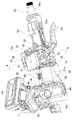
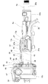
図1〜図9は、本発明の実施の形態の1例を示している。ステアリング装置は、ステアリングコラム6aと、1対の被挟持部13aと、1対のテレスコ調節用長孔23aと、ステアリングシャフト5aと、支持ブラケット15aと、1対の車体側貫通孔である1対のチルト調節用長孔18aと、調節ロッド17aと、1対の押圧部24a、24bと、拡縮装置と、カム部材27と、ストッパ部材28とを備える。
1 to 9 show an example of an embodiment of the present invention. The steering device includes a
ステアリングコラム6aは、鉄系合金やアルミニウム系合金などの金属製であり、円筒状のインナコラム21aと円筒状のアウタコラム22aとを有し、前側に配置されたインナコラム21aの後部と、後側に配置されたアウタコラム22aの前部とを、軸方向の変位を可能に嵌合することにより構成されている。好ましくは、アウタコラム22aの前部の上部または下部(図示の例では上部)には、軸方向に伸長するスリット29が設けられ、アウタコラム22aは、スリット29aによりアウタコラム22aの前部の直径を弾性的に拡縮可能に構成される。インナコラム21aの前端部には、鉄系合金やアルミニウム系合金などの金属製または合成樹脂製のハウジング10aが結合固定されている。ハウジング10aには、電動式パワーステアリング装置の構成部品である減速機やトルク測定器などが収められ、かつ、この電動式パワーステアリング装置の動力源である電動モータ11が支持されている。ハウジング10aは、ハウジング10aの上部前端に幅方向に配設された支持管30に挿通されたボルトなどのチルト用枢軸により、車体に対し支持されている。ハウジング10aおよびインナコラム21aは、車体への取付状態で、この車体に対する前後位置を規制された状態となる。図示の例では、ハウジング10aが、本発明の固定部材に相当する。なお、固定部材には、インナコラム21aに固定可能で、インナコラム21aとともに車体に対する前後位置を規制された状態で、車体に対し支持されることができる、公知の任意の構造が採用され得る。
The
1対の被挟持部13aは、アウタコラム22aの前部の上面でスリット29を幅方向両側から挟む幅方向2箇所位置に、アウタコラム22aと一体に形成されている。
The pair of sandwiched
1対のテレスコ調節用長孔23aは、1対の被挟持部13aの互いに整合する部分に、アウタコラム22aの軸方向に伸長する状態で設けられている。
The pair of telescopic adjustment
1対の被挟持部13aの内側面のうち、1対のテレスコ調節用長孔23aよりも前側に位置する部分の一部(図示の例では、下端部ないしは中間部)、1対のストッパ片31が、幅方向内側に向けて突出する状態で設けられている。1対のストッパ片31の下端部は、アウタコラム22aの上面に結合されており、ステアリングホイール1(図10参照)の前後位置を調節する際や二次衝突の際には、アウタコラム22aとともに前方に変位する。すなわち、1対のストッパ片31が、本発明のアウタコラムとともに前方に変位する部分に相当する。
A part of the inner surface of the pair of sandwiched
ステアリングシャフト5aは、前側に配置されたインナシャフト19aの後部と、後側に配置されたアウタシャフト20aの前部とを、スプライン係合などの非円形嵌合により、トルクの伝達を可能に、かつ、軸方向の変位を可能に組み合わせた構造を有し、ステアリングコラム6aの内側に回転自在に支持されている。インナシャフト19aは、インナコラム21aの内側に、単列深溝型の玉軸受などのラジアル荷重およびスラスト荷重を支承可能な転がり軸受により、回転のみ可能に支持されている。アウタシャフト20aは、アウタコラム22aの内側に、単列深溝型の玉軸受などのラジアル荷重およびスラスト荷重を支承可能な転がり軸受により、回転のみ可能に支持されている。したがって、ステアリングシャフト5aは、ステアリングコラム6aの伸縮に伴って伸縮する。アウタシャフト20aの後端部で、アウタコラム22aの後端開口よりも後方に突出した部分には、ステアリングホイール1が支持固定される。
The steering
支持ブラケット15aは、車体に対し、二次衝突時に加わる衝撃荷重により前方への離脱(変位)を可能に支持される取付板部32と、取付板部32の下面から垂下する状態で設けられた、互いにほぼ平行な1対の支持板部16aとを有する。取付板部32は、取付板部32の幅方向両端部に、取付板部32の後端縁に開口する状態で形成された1対の係止切り欠き34を有する。1対の支持板部16aは、1対の被挟持部13aを幅方向両側から挟む位置に配置されている。支持ブラケット15aは、車体に対して、二次衝突が発生する以前の通常時にはステアリングコラム6aを十分な剛性で保持できるように、二次衝突の発生時には、該二次衝突に伴う衝撃荷重に基づいて前方への離脱を可能に、支持される。1対の係止部材33は、1対の係止部材33の幅方向中央部に形成された1対の通孔35を有し、1対の通孔35を挿通した1対のボルトまたはスタッドにより車体に対し固定され、1対の係止部材33に1対の係止切り欠き34が係止される。二次衝突の発生時に、支持ブラケット15aに前方に向いた衝撃荷重が加わると、1対の係止部材33が1対の係止切り欠き34から後方に抜け出して、支持ブラケット15aが車体に対し前方に離脱することが許容される。支持ブラケット15aが前方に離脱するのに要する荷重、換言すれば、車体に対する支持ブラケット15aの支持強度は、たとえば、1対の係止切り欠き34と1対の係止部材33との係合部に作用する摩擦力を変えることによって調整することができる。支持ブラケット15aと1対の係止部材33との間に、支持ブラケット15aの前方への離脱の際に破断する樹脂製のピンを掛け渡すように設けている場合、ピンの本数、直径、材質などを変更することにより、車体に対する支持ブラケット15aの支持強度を調整することもできる。支持ブラケット15aと1対の係止部材33との間に、支持ブラケット15aの前方への離脱に伴って塑性変形する金属製の衝撃吸収部材を掛け渡すように設けている場合、衝撃吸収部材の形状や材質などを変更することにより、車体に対する支持ブラケット15aの支持強度を調整することもできる。
The
1対のチルト調節用長孔18aは、1対の支持板部16aの互いに整合する部分に、上下方向に伸長する状態で、支持管30に挿通したチルト用枢軸を中心とする円弧状に形成されている。なお、1対のチルト調節用長孔18aは、前記チルト用枢軸を中心とする円弧の接線方向に、上下方向に伸張する状態で、形成されることもできる。
The pair of tilt adjusting
調節ロッド17aは、1対のテレスコ調節用長孔23aと1対のチルト調節用長孔18aとを幅方向に挿通する状態で配置されている。
The
1対の押圧部24a、24bは、調節ロッド17aの両端部で、1対の支持板部16aの外側面から突出した部分に設けられている。
The pair of
拡縮装置は、調節ロッド17aの一端部に設けられた調節レバー25の回動に伴って、1対の押圧部24a、24b同士の間隔を拡縮するように構成される。この拡縮装置としては、たとえば、駆動側カムと被駆動側カムにより構成されるカム装置や、ボルトとナットにより構成されるねじ装置などが採用され得る。
The expansion / contraction device is configured to expand or contract the distance between the pair of
カム部材27は、調節ロッド17aのうち、調節ロッド17aの軸方向中間部で1対の被挟持部13a同士の間に位置する部分に外嵌固定されており、幅方向から見た形状がオーバル形で、周方向の1箇所に、調節ロッド17aの外周面からの径方向に関する突出量が他の部分に比べて大きくなった先端部を有する。カム部材27の形状は、図示のようなオーバル形に限られない。たとえば、カム部材27を、周方向の1箇所位置に、径方向外方に突出するピン部により構成して、該ピン部を、調節ロッド17aの外周面からの径方向に関する突出量が他の部分に比べて大きくなった先端部として機能させることもできる。図示の例では、カム部材27の先端部は、調節レバー25を図4および図5に示す位置まで上方に回動させ、ステアリングホイール1を調節後の位置に保持した状態では、後ろ斜め上方を向いた状態となり、調節レバー25を図6および図7に示す位置まで下方に回動させ、ステアリングホイール1の位置を調節可能とした状態では、後方を向いた状態となる。
The
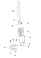
図示の例では、ストッパ部材28は、合成樹脂により全体を一体に造られており、前側に配置されたストッパ本体36と、後側に配置されたリフト部37とを備え、ステアリングコラム6aの前半部の上面と対向する位置に設けられている。
In the illustrated example, the
ストッパ本体36は、ステアリングコラム6aの中心軸とほぼ平行となる方向である前後方向に伸長した長矩形板状で、第1緩衝部38と、幅狭部39と、第1通孔40と、1対のストッパ面41とを有する。第1緩衝部38は、ストッパ本体36の長さ方向中間部の幅方向中間部および幅方向両端部に、上下方向に貫通するかまたは上下方向に貫通するとともに幅方向両側面に開口する状態で複数の肉抜き部を形成することにより、ストッパ本体36の長さ方向中間部に設けられており、ストッパ本体36の他の部分に比べて、長さ方向に関して弾性的に圧縮変形しやすくなっている。幅狭部39は、ストッパ本体36の前端部に設けられ、後側に隣接する部分に比べて幅寸法が狭くなっている。第1通孔40は、断面形状が円形で、幅狭部39に幅方向に設けられている。1対のストッパ面41は、ストッパ本体36の後端面の幅方向両端部に設けられ、ストッパ本体36の長さ方向に対して直交する同一の仮想平面内に配置されている。
The
リフト部37は、ストッパ本体36の後端面のうち、1対のストッパ面41同士の間に挟まれた部分である幅方向中央部から、後方に向けて延出する状態で設けられている。リフト部37は、前端部に第2緩衝部42を備えている。第2緩衝部42は、上下方向に関する波形に形成されたもので、リフト部37の他の部分、および、ストッパ本体36のうちの第1緩衝部38以外の部分に比べて、長さ方向に関して弾性的に圧縮変形しやすくなっている。リフト部37のうち、第2緩衝部42以外の部分は、第2緩衝部42の後端面の上端部から後方に向け延出する状態で設けられており、長矩形板状に構成されている。
The
図示の例では、ストッパ部材28の前端部を構成する幅狭部39の最前部には、ストッパ部材28と同じ種類の合成樹脂により造られた板ばねである付勢ばね43が、ストッパ部材28と一体に設けられている。付勢ばね43は、幅狭部39の最前部から上方に向け直角に折れ曲がる状態で設けられた長矩形板状の起立板部44と、起立板部44の上端部から前方に向け180度折り返された半円弧板状の折り返し板部45と、折り返し板部45の前端部から垂下した短矩形板状の垂下板部46と、垂下板部46の下端部から前方に向け直角に折れ曲がる状態で設けられた短矩形板状の張り出し板部47とから構成されている。
In the illustrated example, an urging
図示の例では、ハウジング10aの後端面のうち、幅方向中央部の上端寄り部分に、互いに平行な1対の固定板49が、幅方向に離隔した状態で突設されている。1対の固定板49のうち互いに整合する部分に、断面形状が円形である1対の第2通孔50が、互いに同心に設けられている。ストッパ部材28の前端部は、幅狭部39が1対の固定板49同士の間部分に配置された状態で、幅狭部39に設けられた第1通孔40と、1対の第2通孔50とに掛け渡す状態で、ストッパ用枢軸であるピン48を設置することで、ハウジング10aの後端部に対して枢支されている。具体的には、図8(A)に示すように、ピン48の両端部を1対の第2通孔50に圧入により内嵌固定するとともに、ピン48の中間部を、枢軸用通孔である第1通孔40に緩く挿通する。または、図8(B)に示すように、ピン48の中間部を第1通孔40に圧入により内嵌固定するとともに、ピン48の両端部を、それぞれが枢軸用通孔である1対の第2通孔50に緩く挿通する。図8(B)の構造を採用する場合、ピン48をストッパ部材28と一体に設ける、すなわち、ストッパ部材28を構成する合成樹脂により造ることもできる。いずれにしても、ストッパ部材28の前端面がハウジング10aの後端面に衝突した状態で、ピン48の外周面が、枢軸用通孔である第1通孔40または1対の第2通孔50の内周面に強く押し付けられることがないように、ピン48の外径や第1通孔40または1対の第2通孔50の内径が規制されている。
In the illustrated example, a pair of fixing
ストッパ部材28の前端部をピン48により枢支した状態で、リフト部37の下面を、カム部材27の外周面に軽い力で押し付けるともに、付勢ばね43を構成する張り出し板部47の前端部を、ハウジング10aの後端面の上端部に対し、付勢ばね43の弾力に基づいて押し付けている。付勢ばね43の弾力に基づく押し付け力は、ストッパ部材28をピン48を中心としてステアリングコラム6a側に向け揺動させる力に変換され、リフト部37の下面は、カム部材27の外周面に弾性的に押し付けられる。リフト部37がカム部材27の外周面に弾性的に押し付けられた状態では、ストッパ部材28を構成する第2緩衝部42の弾力も、リフト部37の下面をカム部材27の外周面に弾性的に押し付ける力として作用する。リフト部37の下面をカム部材27の外周面に弾性的に押し付けることにより、カム部材27の外周面に対するリフト部37の下面の追従性が良好になる。ただし、リフト部37の下面をカム部材27の外周面に弾性的に押し付ける力は、ステアリングホイール1の前後位置を調節する際に、アウタコラム22aの前後方向変位が阻害されることがない程度に小さくなっている。図示の例では、付勢ばね43がストッパ部材28と一体に形成されているため、部品点数の減少によるコストの低減および組立性の向上が図られている。
With the front end portion of the
ステアリングホイール1の上下位置または前後位置を調節する際には、調節レバー25を、図4および図5に示す位置から、図6および図7に示す位置まで下方に回動させ、拡縮装置を操作することにより、1対の押圧部24a、24b同士の間隔(図2の左右方向の間隔)が拡がる。これにより、アウタコラム22aの前部の直径が弾性的に拡がって、アウタコラム22aの前部内周面とインナコラム21aの後部外周面との当接部の面圧が低下あるいは喪失し、かつ、1対の支持板部16aの内側面と1対の被挟持部13aの外側面との当接部の面圧が低下あるいは喪失する。この状態で、調節ロッド17aが、1対のテレスコ調節用長孔23aおよび1対のチルト調節用長孔18a内で変位できる範囲で、ステアリングホイール1の位置が調節可能となる。調節後は、調節レバー25を、図6および図7に示す位置から、図4および図5に示す位置まで上方に回動させ、拡縮装置を操作することにより、1対の押圧部24a、24b同士の間隔が縮まる。これにより、アウタコラム22aの前部内周面とインナコラム21aの後部外周面との当接部の面圧が大きくなり、かつ、1対の支持板部16aの内側面と1対の被挟持部13aの外側面との当接部の面圧も大きくなって、ステアリングホイール1が調節後の位置に保持される。
When adjusting the vertical position or the front-rear position of the steering wheel 1, the
調節レバー25を、図6および図7に示す位置まで下方に回動させた状態、すなわち、ステアリングホイール1の位置調節を可能とした状態では、カム部材27の先端部が後方に向いた状態となる。これにより、ストッパ部材28を構成するリフト部37が下方に変位し、1対のストッパ面41も下方に変位する。1対のストッパ面41が下方に変位した状態では、ステアリングホイール1の前後位置にかかわらず、1対のストッパ面41のうちの少なくとも下端部が、1対のストッパ片31の前端面のうちの少なくとも上端部と、ステアリングコラム6aの軸方向に関して対向した状態になる。1対のストッパ面41が下方に変位した状態で、アウタコラム22aを前方に変位させると、図7に示すように、1対のテレスコ調節用長孔23aの後端部が調節ロッド17aの外周面に衝突する以前に、1対のストッパ片31の前端面が1対のストッパ面41と衝突(当接)して、ストッパ部材28を構成するストッパ本体36が、ハウジング10aの後端面と1対のストッパ片31の前端面との間で前後方向に挟持される。すなわち、1対のストッパ片31の前端面と1対のストッパ面41とが衝突する位置が、ステアリングホイール1の位置調節可能範囲の前端位置となる。
When the
調節レバー25を、図4および図5に示す位置まで上方に回動させた状態、すなわち、ステアリングホイール1を調節後の位置に保持した状態では、カム部材27の先端部が斜め後ろ上方に向いた状態となる。これにより、ストッパ部材28を構成するリフト部37が上方に変位し、1対のストッパ面41も上方に変位する。1対のストッパ面41が上方に変位した状態では、ステアリングホイール1の前後位置にかかわらず、1対のストッパ面41の全体が、1対のストッパ片31の前端面よりも上方に位置した状態、すなわち、1対のストッパ面41と1対のストッパ片31の前端面とが、ステアリングコラム6aの軸方向に対向しない状態となる。
When the
このような構成のステアリング装置では、ステアリングホイール1の前後位置を調節する際に、ステアリングホイール1を前端位置まで勢いよく変位させた場合でも、支持ブラケット15aに前方に向いた衝撃が加わることを防止できる。すなわち、ステアリングホイール1の前後位置の調節を可能とするために、調節レバー25を、図6および図7に示す位置まで下方に回動させ、拡縮装置により1対の押圧部24a、24b同士の間隔を拡げた状態では、ステアリングホイール1を変位させることにより、アウタコラム22aを前方に変位させると、図7に示すように、1対のテレスコ調節用長孔23aの後端部が調節ロッド17aの外周面に衝突する以前に、1対のストッパ片31の前端面が1対のストッパ面41と衝突(当接)し、ストッパ本体36が、ハウジング10aの後端面と1対のストッパ片31の前端面との間で前後方向に挟持された状態となって、1対のテレスコ調節用長孔23aの後端部と調節ロッド17aの外周面との衝突が防止される。1対のストッパ片31の前端面が1対のストッパ面41と衝突した状態では、ステアリングホイール1からアウタコラム22aに加わる前方に向いた力は、ストッパ本体36およびハウジング10aを介して車体に支承される。したがって、ステアリングホイール1の前後位置を調節する際に、ステアリングホイール1を前端位置まで勢いよく変位させた場合でも、ステアリングホイール1からアウタコラム22aに加わる前方に向いた力が、調節ロッド17aを介して支持ブラケット15aに伝わることが阻止され、もって支持ブラケット15aに前方に向いた衝撃が加わることが防止される。
In the steering device having such a configuration, even when the steering wheel 1 is displaced to the front end position when adjusting the front-rear position of the steering wheel 1, it is possible to prevent a forward impact from being applied to the
図示の例では、ストッパ部材28は、前側に配置されるストッパ本体36と後側に配置されるリフト部37とから構成され、ストッパ本体36のみが、ハウジング10aの後端面と1対のストッパ片31の前端面との間で前後方向に挟持される。したがって、長尺なストッパ部材28の全体がハウジング10aの後端面と1対のストッパ片31の前端面との間で前後方向に挟持される構成を採用する場合に比べて、前後方向に挟持される部分の座屈強度を高めることができる。1対のストッパ片31の前端面が1対のストッパ面41に衝突した際の衝撃が、ストッパ本体36の第1緩衝部38が弾性的に圧縮されることにより緩和される。ストッパ本体36が、ハウジング10aの後端面と1対のストッパ片31の前端面との間で前後方向に挟持された状態、すなわち、ストッパ部材28の前端面がハウジング10aの後端面に当接した状態でも、ピン48の外周面が、枢軸用通孔である第1通孔40または第2通孔50の内周面に強く押し付けられないようになっているため、ピン48や1対の固定板49が破損してしまうことが防止される。
In the illustrated example, the
ステアリングホイール1を調節後の位置に保持するため、調節レバー25を、図4および図5に示す位置まで上方に回動させ、拡縮装置により1対の押圧部24a、24b同士の間の間隔を縮めた状態では、1対のストッパ面41の全体が、1対のストッパ片31の前端面よりも上方に位置する。したがって、二次衝突時の衝撃荷重により、アウタコラム22aが前方に変位した場合でも、1対のストッパ片31の前端面が1対のストッパ面41と衝突することが阻止され、1対のテレスコ調節用長孔23aaの後端部が調節ロッド17aに当接することが許容される。この結果、二次衝突時の衝撃荷重を、調節ロッド17aを介して支持ブラケット15aに伝えることができて、支持ブラケット15aを車体に対し前方に離脱(変位)させて、運転者に加わる衝撃荷重を緩和することができる。ステアリングホイール1の前後位置を調節する際に、ステアリングホイール1を前端位置まで勢いよく変位させた場合でも、支持ブラケット15aに前方に向いた衝撃が加わらないようにできる。要するに、車体に対する支持ブラケット15aの支持強度を決定する場合に、ステアリングホイール1の前後位置を調節する際に支持ブラケット15aに前方に向いた衝撃荷重が加わることを考慮する必要がなく、支持ブラケット15aの支持強度の設計を容易化できて、二次衝突時に運転者に加わる衝撃荷重の緩和を図り易い。
In order to hold the steering wheel 1 in the adjusted position, the
二次衝突時に、支持ブラケット15aが車体に対し前方に変位する過程で、カム部材27が、ストッパ部材28を構成する第2緩衝部42の後端面の下端部ないしは中間部に衝突する可能性があるが、仮にカム部材27が第2緩衝部42に衝突した場合でも、第2緩衝部42と第1緩衝部38とが前後方向に関して弾性的に圧縮されて、衝突に基づく衝撃を緩和できる。また、カム部材27が第2緩衝部42に衝突した状態で、カム部材27の前端面ないしは上面は、図5に示すように、後方に向かうに従って上方に向かう方向に傾斜した状態となっている。このため、衝突が起こった直後に、第2緩衝部42がカム部材27の上面に円滑に乗り上がって、支持ブラケット15aの前方への変位が、引き続き許容される。
During the secondary collision, the
本発明を実施する場合、支持ブラケットを車体に対し、二次衝突時に加わる衝撃荷重に基づいて前方への離脱を可能に支持する部分の構造は、特に限定されることはなく、幅方向中央1箇所位置に設けられた係止切り欠きに、1個の係止部材を係止する構造なども採用され得る。特開2013−18472号公報に記載されているように、ステアリングコラム構造として、1対の被挟持部を、アウタコラムの前端部を径方向外方に膨出させることにより形成して、アウタコラムとインナコラムとの間にがたつき防止のためのスペーサを設けた構造も採用され得る。 In the case of carrying out the present invention, the structure of the portion that supports the support bracket so as to be able to be detached forward based on the impact load applied to the vehicle body at the time of the secondary collision is not particularly limited. A structure in which one locking member is locked in a locking notch provided at a location may be employed. As described in Japanese Patent Application Laid-Open No. 2013-18472, as a steering column structure, a pair of sandwiched portions are formed by bulging the front end portion of the outer column radially outward, and the outer column A structure in which a spacer for preventing rattling is provided between the inner column and the inner column may be employed.
本発明は、テレスコピック機構とチルト機構とのうちの、テレスコピック機構のみを備えているステアリング装置に適用することもできる。この場合、1対の車体側通孔は、調節ロッドを挿通可能な円孔により構成される。 The present invention can also be applied to a steering device having only a telescopic mechanism of a telescopic mechanism and a tilt mechanism. In this case, the pair of vehicle body side through holes are formed by circular holes through which the adjustment rods can be inserted.
付勢手段の構造は、ストッパ部材を上下方向に関してステアリングコラム側に付勢できる限り、特に問われない。たとえば、付勢手段を弾性部材とする場合、この弾性部材としては、種々の形状のものを採用することができ、ストッパ部材と一体に形成することもできるし、ストッパ部材と別体に形成することもできる。 The structure of the urging means is not particularly limited as long as the stopper member can be urged toward the steering column with respect to the vertical direction. For example, when the urging means is an elastic member, various shapes can be adopted as the elastic member, and the elastic member can be formed integrally with the stopper member or formed separately from the stopper member. You can also.
図示の例では、本発明は、1対の被挟持部13aが、アウタコラム22aの上面の幅方向に離隔した2箇所位置に設けけられており、調節ロッド17aが、アウタコラム22aの上方で、1対の被挟持部13aのテレスコ調節用長孔23aに挿通されるように配置されている。ただし、本発明は、1対の被挟持部が、アウタコラムの下面の幅方向に離隔した2箇所位置に、アウタコラムと一体に設けられ、調節ロッドが、該アウタコラム下方で、前記1対の被挟持部のテレスコ調節用長孔に挿通される構造を有するステアリング装置にも適用可能である。この場合、本発明を構成する1対の押圧部と、拡縮装置と、カム部材と、ストッパ部材の配置および向きが上下方向で逆に構成される。
In the illustrated example, in the present invention, a pair of sandwiched
1 ステアリングホイール
2 ステアリングギヤユニット
3 入力軸
4 タイロッド
5、5a ステアリングシャフト
6、6a ステアリングコラム
7 自在継手
8 中間シャフト
9 自在継手
10、10a ハウジング
11 電動モータ
12 チルト用枢軸
13、13a 被挟持部
14 車体
15、15a 支持ブラケット
16、16a 支持板部
17、17a 調節ロッド
18、18a チルト調節用長孔
19、19a インナシャフト
20、20a アウタシャフト
21、21a インナコラム
22、22a アウタコラム
23、23a テレスコ調節用長孔
24a、24b 押圧部
25 調節レバー
27 カム部材
28 ストッパ部材
29 スリット
30 支持管
31 ストッパ片
32 取付板部
33 係止部材
34 係止切り欠き
35 通孔
36 ストッパ本体
37 リフト部
38 第1緩衝部
39 幅狭部
40 第1通孔
41 ストッパ面
42 第2緩衝部
43 付勢ばね
44 起立板部
45 折り返し板部
46 垂下板部
47 張り出し板部
48 ピン
49 固定板
50 第2通孔DESCRIPTION OF SYMBOLS 1
Claims (8)
前記ステアリングコラムは、インナコラムとアウタコラムとを有し、該インナコラムの後部と該アウタコラムの前部とを、軸方向の相対変位を可能に嵌合することにより構成され、かつ、内側に、伸縮可能なステアリングシャフトが回転自在に支持可能であり、
前記1対の被挟持部は、前記アウタコラムの上面または下面の幅方向に離隔した2箇所位置に、該アウタコラムと一体に設けられており、
前記1対のテレスコ調節用長孔は、前記1対の被挟持部の互いに整合する部分に、前記アウタコラムの軸方向に伸長する状態で設けられており、
前記支持ブラケットは、前記1対の被挟持部を幅方向両側から挟む1対の支持板部を有し、車体に対し、二次衝突時に加わる荷重に基づいて前方への離脱を可能に支持されており、
前記1対の車体側貫通孔は、前記1対の支持板部の互いに整合する部分に設けられており、
前記調節ロッドは、前記1対のテレスコ調節用長孔と前記1対の車体側貫通孔とを幅方向に挿通する状態で設けられており、
前記1対の押圧部は、前記調節ロッドの両端部で、前記1対の支持板部の外側面から突出した部分に設けられており、
前記拡縮装置は、前記1対の押圧部同士の間隔を拡縮するものであり、
前記カム部材は、前記調節ロッドのうち、該調節ロッドの軸方向中間部で前記1対の被挟持部同士の間に位置する部分に固定されており、
前記固定部材は、前記車体に対する前後位置を規制された状態で設けられており、
前記ストッパ部材は、前記固定部材に支持された状態で後方に向いたストッパ面と、前記固定部材に支持された状態で前記ステアリングコラムの外周面と対向し、かつ、前記カム部材の外周面に当接する上下方向片側面とを有し、および、前記拡縮装置により前記1対の押圧部同士の間隔を拡げた状態で、前記ストッパ面が、前記カム部材により前記ステアリングコラム側に変位させられ、前記アウタコラムが前方に変位した場合において、前記1対のテレスコ調節用長孔の後端部と前記調節ロッドの外周面とが衝突する以前に、前記ストッパ面と前記アウタコラムとともに前方に変位する部分とが衝突し、前記拡縮装置により前記1対の押圧部同士の間隔を縮めた状態では、前記ストッパ面が、前記カム部材により前記ステアリングコラムから離れる方向に変位させられ、前記アウタコラムが前方に変位した場合でも、前記1対のテレスコ調節用長孔の後端部と前記調節ロッドの外周面とが衝突する以前に、前記ストッパ面と前記アウタコラムとともに前方に変位する部分とが衝突することがないように、構成されている、
ステアリング装置。A steering column, a pair of sandwiched portions, a pair of telescopic adjustment long holes, a support bracket, a pair of vehicle body side through holes, an adjustment rod, a pair of pressing portions, and an expansion / contraction device, A cam member, a fixing member, and a stopper member;
The steering column includes an inner column and an outer column, and is configured by fitting a rear portion of the inner column and a front portion of the outer column so as to be capable of relative displacement in the axial direction, and on the inner side. The telescopic steering shaft can be rotatably supported,
The pair of sandwiched portions are provided integrally with the outer column at two positions spaced in the width direction of the upper surface or the lower surface of the outer column,
The pair of telescopic adjustment long holes are provided in a state in which the pair of sandwiched portions are aligned with each other so as to extend in the axial direction of the outer column,
The support bracket includes a pair of support plate portions that sandwich the pair of sandwiched portions from both sides in the width direction, and is supported so as to be able to be detached forward based on a load applied to the vehicle body during a secondary collision. And
The pair of vehicle body side through holes are provided in portions of the pair of support plate portions that are aligned with each other,
The adjustment rod is provided in a state of passing through the pair of telescopic adjustment long holes and the pair of vehicle body side through holes in the width direction,
The pair of pressing portions are provided at portions projecting from the outer surfaces of the pair of support plate portions at both ends of the adjustment rod,
The expansion / contraction device expands / contracts an interval between the pair of pressing portions,
The cam member is fixed to a portion of the adjusting rod that is positioned between the pair of sandwiched portions at an intermediate portion in the axial direction of the adjusting rod.
The fixing member is provided in a state in which a front-rear position with respect to the vehicle body is regulated,
The stopper member is supported by the fixing member and faces the stopper surface facing backward, the outer peripheral surface of the steering column while being supported by the fixing member, and on the outer peripheral surface of the cam member. The stopper surface is displaced to the steering column side by the cam member in a state in which the one-side surface in contact with the upper and lower sides is in contact and the space between the pair of pressing portions is expanded by the expansion / contraction device. When the outer column is displaced forward, it is displaced forward together with the stopper surface and the outer column before the rear end portions of the pair of telescopic adjustment long holes collide with the outer peripheral surface of the adjustment rod. In the state where the portion collides and the distance between the pair of pressing portions is reduced by the expansion / contraction device, the stopper surface is moved by the cam member to the steering column. Even if the outer column is displaced forward, the stopper surface and the rear end portion of the pair of telescopic adjustment long holes and the outer peripheral surface of the adjustment rod collide with each other. It is configured so that it does not collide with the outer column and the part displaced forward,
Steering device.
前記ストッパ部材は、前端部と後端面を有するストッパ本体を備え、前記ストッパ面は、該ストッパ本体の後端面に設けられており、前記ストッパ本体の前端部は前記固定部材に対し支持されており、
前記ストッパ面と前記アウタコラムとともに前方に変位する部分とが衝突した状態で、前記ストッパ本体が、該アウタコラムとともに前方に変位する部分と前記固定部材との間で前後方向に挟持される、
請求項1に記載のステアリング装置。The fixing member is disposed on the front side of the inner column,
The stopper member includes a stopper main body having a front end portion and a rear end surface, the stopper surface is provided on a rear end surface of the stopper main body, and the front end portion of the stopper main body is supported by the fixing member. ,
In a state where the stopper surface and a portion displaced forward together with the outer column collide, the stopper main body is sandwiched in the front-rear direction between the portion displaced forward together with the outer column and the fixing member.
The steering apparatus according to claim 1.
請求項1に記載のステアリング装置。The stopper member has urging means, and the stopper member is urged toward the steering column side in the vertical direction by the urging means.
The steering apparatus according to claim 1.
前記ストッパ部材は、前記付勢手段により、前記ストッパ用枢軸を中心として前記ステアリングコラム側に揺動する方向に付勢されている、
請求項4に記載のステアリング装置。The stopper member is supported pivotably with respect to the fixed member by a stopper pivot arranged in the width direction,
The stopper member is urged by the urging means in a direction of swinging toward the steering column side about the stopper pivot.
The steering apparatus according to claim 4.
Applications Claiming Priority (3)
| Application Number | Priority Date | Filing Date | Title |
|---|---|---|---|
| JP2015005129 | 2015-01-14 | ||
| JP2015005129 | 2015-01-14 | ||
| PCT/JP2016/051035 WO2016114366A1 (en) | 2015-01-14 | 2016-01-14 | Steering device |
Publications (2)
| Publication Number | Publication Date |
|---|---|
| JP5975199B1 true JP5975199B1 (en) | 2016-08-23 |
| JPWO2016114366A1 JPWO2016114366A1 (en) | 2017-04-27 |
Family
ID=56405906
Family Applications (1)
| Application Number | Title | Priority Date | Filing Date |
|---|---|---|---|
| JP2016530024A Active JP5975199B1 (en) | 2015-01-14 | 2016-01-14 | Steering device |
Country Status (5)
| Country | Link |
|---|---|
| US (1) | US10086865B2 (en) |
| EP (1) | EP3225505B1 (en) |
| JP (1) | JP5975199B1 (en) |
| CN (1) | CN107107946B (en) |
| WO (1) | WO2016114366A1 (en) |
Cited By (1)
| Publication number | Priority date | Publication date | Assignee | Title |
|---|---|---|---|---|
| KR20190113283A (en) * | 2018-03-28 | 2019-10-08 | 남양넥스모 주식회사 | steering column |
Families Citing this family (3)
| Publication number | Priority date | Publication date | Assignee | Title |
|---|---|---|---|---|
| DE102015216536B3 (en) * | 2015-08-28 | 2017-02-16 | Thyssenkrupp Ag | Clamping device of an adjustable steering column for motor vehicles |
| JP6905918B2 (en) * | 2017-11-17 | 2021-07-21 | 株式会社山田製作所 | Steering device |
| US10858032B2 (en) * | 2018-11-29 | 2020-12-08 | Steering Solutions Ip Holding Corporation | Clamp load adjustment assembly for steering column |
Citations (5)
| Publication number | Priority date | Publication date | Assignee | Title |
|---|---|---|---|---|
| JP2008308072A (en) * | 2007-06-15 | 2008-12-25 | Mitsubishi Motors Corp | Shock absorbing structure of steering column device |
| US20110210536A1 (en) * | 2008-06-04 | 2011-09-01 | Zf Systemes De Direction Nacam Sas | Adjustable steering column for motor vehicles |
| JP2013124079A (en) * | 2011-12-16 | 2013-06-24 | Nsk Ltd | Position adjusting type steering column device for vehicle |
| JP2014051129A (en) * | 2012-09-05 | 2014-03-20 | Kayaba Ind Co Ltd | Steering system |
| JP2014129087A (en) * | 2011-04-14 | 2014-07-10 | Nsk Ltd | Steering device |
Family Cites Families (31)
| Publication number | Priority date | Publication date | Assignee | Title |
|---|---|---|---|---|
| ES2161127B1 (en) * | 1999-03-16 | 2002-09-01 | Castellon Melchor Daumal | TELESCOPIC TREE FOR STEERING COLUMNS IN CAR VEHICLES WITH SLIDING SYSTEM WITH LOAD CONTROL. |
| DE10057861A1 (en) * | 2000-11-21 | 2002-05-23 | Mkl Miniaturkugellager Gmbh | Ball bearing for high speed devices has at least one device to produce RPM-dependent clamping force for bracing of bearing and comprises at least a part of balls of bearing |
| JP4254194B2 (en) * | 2002-10-10 | 2009-04-15 | 日本精工株式会社 | Telescopic shaft for vehicle steering |
| CN100460259C (en) * | 2002-11-29 | 2009-02-11 | 日本精工株式会社 | Telescoping shaft for vehicle steering |
| JP4696916B2 (en) * | 2004-01-27 | 2011-06-08 | 日本精工株式会社 | Telescopic shaft for vehicle steering |
| US8047096B2 (en) * | 2007-03-30 | 2011-11-01 | Nexteer (Beijing) Technology Co., Ltd. | Lock mechanism for an adjustable steering column assembly |
| JP2009090856A (en) * | 2007-10-10 | 2009-04-30 | Nsk Ltd | Steering device |
| EP2197728A4 (en) * | 2007-10-15 | 2012-12-05 | Deok Chang Machinery Co Ltd | Telescopic shaft for vehicle |
| JP5030744B2 (en) * | 2007-11-26 | 2012-09-19 | Ntn株式会社 | Bearing device |
| US8375822B2 (en) * | 2009-05-29 | 2013-02-19 | Steering Solutions Ip Holding Corporation | Energy absorbing device for a collapsible steering column assembly |
| JP5327179B2 (en) | 2010-10-15 | 2013-10-30 | 日本精工株式会社 | Steering column support device |
| JP2012167814A (en) * | 2011-01-25 | 2012-09-06 | Nsk Ltd | Rolling bearing |
| JP5609838B2 (en) | 2011-06-16 | 2014-10-22 | 日本精工株式会社 | Steering column device |
| JP5917030B2 (en) * | 2011-06-30 | 2016-05-11 | Ntn株式会社 | Rolling bearing |
| JP5865805B2 (en) * | 2012-09-05 | 2016-02-17 | Kyb株式会社 | Steering device |
| JP2015044507A (en) * | 2013-07-31 | 2015-03-12 | 株式会社ジェイテクト | Steering device |
| CN105764772A (en) * | 2013-10-04 | 2016-07-13 | Nsk美国有限公司 | Collapsible steering column assembly |
| WO2015064393A1 (en) * | 2013-10-30 | 2015-05-07 | 日本精工株式会社 | Steering device |
| DE102014101194B4 (en) * | 2014-01-31 | 2015-09-10 | Thyssenkrupp Ag | Steering shaft for a motor vehicle |
| DE102014105822B4 (en) * | 2014-04-25 | 2016-03-03 | Thyssenkrupp Presta Ag | Steering shaft for a motor vehicle |
| GB201411629D0 (en) * | 2014-06-30 | 2014-08-13 | Trw Ltd | Telescopic steering column assembly |
| EP3101295B1 (en) * | 2014-07-03 | 2018-10-03 | NSK Ltd. | Extensible rotation transmission shaft |
| CN107074267B (en) * | 2014-11-10 | 2018-05-18 | 日本精工株式会社 | Impact-absorbing steering device |
| EP3190027B1 (en) * | 2014-12-18 | 2019-05-08 | NSK Ltd. | Steering apparatus |
| US9849906B2 (en) * | 2015-03-27 | 2017-12-26 | Fuji Kiko Co., Ltd. | Steering column device |
| JP5980992B1 (en) * | 2015-06-04 | 2016-08-31 | Dmg森精機株式会社 | Machine tool bearing lubrication system |
| JP6604162B2 (en) * | 2015-11-25 | 2019-11-13 | 株式会社ジェイテクト | Planetary roller type transmission, its assembling method and its mounting method |
| JP6642827B2 (en) * | 2016-02-12 | 2020-02-12 | 株式会社ジェイテクト | Steering device |
| JP6694739B2 (en) * | 2016-03-25 | 2020-05-20 | 富士機工株式会社 | Steering column device |
| KR101639036B1 (en) * | 2016-04-25 | 2016-07-12 | 서한산업(주) | Telescopic Shaft |
| DE102016224271A1 (en) * | 2016-12-06 | 2017-02-02 | Thyssenkrupp Ag | Steering shaft for a motor vehicle |
-
2016
- 2016-01-14 WO PCT/JP2016/051035 patent/WO2016114366A1/en active Application Filing
- 2016-01-14 US US15/127,905 patent/US10086865B2/en active Active
- 2016-01-14 CN CN201680005821.1A patent/CN107107946B/en active Active
- 2016-01-14 JP JP2016530024A patent/JP5975199B1/en active Active
- 2016-01-14 EP EP16737437.0A patent/EP3225505B1/en active Active
Patent Citations (5)
| Publication number | Priority date | Publication date | Assignee | Title |
|---|---|---|---|---|
| JP2008308072A (en) * | 2007-06-15 | 2008-12-25 | Mitsubishi Motors Corp | Shock absorbing structure of steering column device |
| US20110210536A1 (en) * | 2008-06-04 | 2011-09-01 | Zf Systemes De Direction Nacam Sas | Adjustable steering column for motor vehicles |
| JP2014129087A (en) * | 2011-04-14 | 2014-07-10 | Nsk Ltd | Steering device |
| JP2013124079A (en) * | 2011-12-16 | 2013-06-24 | Nsk Ltd | Position adjusting type steering column device for vehicle |
| JP2014051129A (en) * | 2012-09-05 | 2014-03-20 | Kayaba Ind Co Ltd | Steering system |
Cited By (2)
| Publication number | Priority date | Publication date | Assignee | Title |
|---|---|---|---|---|
| KR20190113283A (en) * | 2018-03-28 | 2019-10-08 | 남양넥스모 주식회사 | steering column |
| KR102398780B1 (en) | 2018-03-28 | 2022-05-17 | 남양넥스모 주식회사 | steering column |
Also Published As
| Publication number | Publication date |
|---|---|
| EP3225505A4 (en) | 2018-01-10 |
| CN107107946B (en) | 2018-07-10 |
| CN107107946A (en) | 2017-08-29 |
| US10086865B2 (en) | 2018-10-02 |
| EP3225505B1 (en) | 2018-12-26 |
| US20170355393A1 (en) | 2017-12-14 |
| WO2016114366A1 (en) | 2016-07-21 |
| JPWO2016114366A1 (en) | 2017-04-27 |
| EP3225505A1 (en) | 2017-10-04 |
Similar Documents
| Publication | Publication Date | Title |
|---|---|---|
| JP5812194B2 (en) | Electric steering wheel position adjustment device | |
| JP5070795B2 (en) | Steering wheel position adjustment device | |
| JP5975199B1 (en) | Steering device | |
| JP6142967B2 (en) | Telescopic steering device | |
| JP6048617B2 (en) | Steering wheel position adjustment device | |
| JP5737456B2 (en) | Steering column and telescopic steering device | |
| JP6455200B2 (en) | Cam device with speed reduction mechanism and steering wheel position adjusting device | |
| JP5891876B2 (en) | Steering device | |
| JPWO2017069186A1 (en) | Outer column with bracket, steering column with bracket, and steering device | |
| JP7310166B2 (en) | steering column device | |
| JP2018024400A (en) | Telescopic steering column and steering wheel position adjustment device | |
| JP6710984B2 (en) | Steering wheel position adjustment device | |
| JP6379863B2 (en) | Steering wheel position adjusting device and manufacturing method thereof | |
| JP6384225B2 (en) | Steering column support device | |
| JP6668619B2 (en) | Telescopic steering column device | |
| JP5967234B2 (en) | Tilt-type steering device | |
| JP5895754B2 (en) | Steering wheel position adjustment device | |
| JP2016032955A (en) | Telescopic steering column and adjustment device of front and back positions of steering wheel | |
| JP6098745B2 (en) | Steering device | |
| JP2016222056A (en) | Tilt-type steering column device | |
| JP2017132323A (en) | Position adjustment device for steering wheel | |
| JP2016068589A (en) | Support device for steering column | |
| JP2016047669A5 (en) | ||
| JP5692257B2 (en) | Tilt-type steering device | |
| JP6094177B2 (en) | Steering wheel position adjustment device |
Legal Events
| Date | Code | Title | Description |
|---|---|---|---|
| A621 | Written request for application examination |
Free format text: JAPANESE INTERMEDIATE CODE: A621 Effective date: 20160511 |
|
| A871 | Explanation of circumstances concerning accelerated examination |
Free format text: JAPANESE INTERMEDIATE CODE: A871 Effective date: 20160511 |
|
| TRDD | Decision of grant or rejection written | ||
| A975 | Report on accelerated examination |
Free format text: JAPANESE INTERMEDIATE CODE: A971005 Effective date: 20160616 |
|
| A01 | Written decision to grant a patent or to grant a registration (utility model) |
Free format text: JAPANESE INTERMEDIATE CODE: A01 Effective date: 20160621 |
|
| A61 | First payment of annual fees (during grant procedure) |
Free format text: JAPANESE INTERMEDIATE CODE: A61 Effective date: 20160704 |
|
| R150 | Certificate of patent or registration of utility model |
Ref document number: 5975199 Country of ref document: JP Free format text: JAPANESE INTERMEDIATE CODE: R150 |
|
| R250 | Receipt of annual fees |
Free format text: JAPANESE INTERMEDIATE CODE: R250 |