JP2016222056A - Tilt-type steering column device - Google Patents
Tilt-type steering column device Download PDFInfo
- Publication number
- JP2016222056A JP2016222056A JP2015108696A JP2015108696A JP2016222056A JP 2016222056 A JP2016222056 A JP 2016222056A JP 2015108696 A JP2015108696 A JP 2015108696A JP 2015108696 A JP2015108696 A JP 2015108696A JP 2016222056 A JP2016222056 A JP 2016222056A
- Authority
- JP
- Japan
- Prior art keywords
- portions
- bracket
- support bracket
- support
- side convex
- Prior art date
- Legal status (The legal status is an assumption and is not a legal conclusion. Google has not performed a legal analysis and makes no representation as to the accuracy of the status listed.)
- Pending
Links
Images


Landscapes
- Steering Controls (AREA)
Abstract
Description
本発明は、運転者の体格や運転姿勢に応じてステアリングホイールの上下位置を調節する為のチルト機構付きのステアリングコラム装置の改良に関する。 The present invention relates to an improvement in a steering column device with a tilt mechanism for adjusting the vertical position of a steering wheel in accordance with the physique and driving posture of a driver.
自動車用のステアリング装置は、図8に示す様に構成して、ステアリングホイール1の回転をステアリングギヤユニット2の入力軸3に伝達し、この入力軸3の回転に伴って左右1対のタイロッド4、4を押し引きして、前車輪に舵角を付与する様にしている。前記ステアリングホイール1は、ステアリングシャフト5の後端部に支持固定しており、このステアリングシャフト5は、円筒状のステアリングコラム6を軸方向に挿通した状態で、このステアリングコラム6に回転自在に支持している。又、前記ステアリングシャフト5の前端部は、自在継手7を介して中間シャフト8の後端部に接続し、この中間シャフト8の前端部を、別の自在継手9を介して、前記入力軸3に接続している。尚、本明細書及び特許請求の範囲全体で、前後方向、左右方向(幅方向)、及び上下方向は、特に断らない限り、車両の前後方向、左右方向(幅方向)、及び上下方向を言う。
The steering device for an automobile is configured as shown in FIG. 8, and transmits the rotation of the steering wheel 1 to the input shaft 3 of the steering gear unit 2, and a pair of left and right tie rods 4 in accordance with the rotation of the input shaft 3. 4 is pushed and pulled to give a steering angle to the front wheels. The steering wheel 1 is supported and fixed to the rear end portion of the
上述の様なステアリング装置として、運転者の体格や運転姿勢に応じ、前記ステアリングホイール1の上下位置を調節する為のチルト機構を組み込んだ構造が、例えば特許文献1等に記載される等して、従来から広く知られている。このチルト機構を構成する為に、図8に示した従来構造の場合には、前記ステアリングコラム6の前端部を車体10に対して、左右方向に設置した枢軸11を中心とする揺動変位を可能に支持している。又、前記ステアリングコラム6の後端寄り部分に支持ブラケット12を設置し、この支持ブラケット12を車体10に対し支持している。この支持ブラケット12は、幅方向に離隔した左右1対の支持板部13を備え、これら両支持板部13により、前記ステアリングコラム6の後端寄り部分に固設した変位ブラケット14を幅方向両側から挟む状態で、前記車体10に対し支持されている。
As a steering apparatus as described above, a structure incorporating a tilt mechanism for adjusting the vertical position of the steering wheel 1 according to the physique and driving posture of the driver is described in, for example, Patent Document 1 It has been widely known. In order to constitute this tilt mechanism, in the case of the conventional structure shown in FIG. 8, the displacement of the steering column 6 with respect to the
そして、前記両支持板部13に上下方向に伸長する上下方向長孔15を、前記変位ブラケット14の一部でこれら両上下方向長孔15の一部に整合する部分にコラム側通孔16を、それぞれ形成している。尚、図8に示した構造は、前記ステアリングホイール1の上下位置を調節する為のチルト機構に加えて、前後位置を調節する為のテレスコピック機構を組み込んでいる為、前記コラム側通孔16を、前記ステアリングシャフト5及び前記ステアリングコラム6の軸方向に伸長する長孔としている。そして、このステアリングコラム6を、後側のアウタコラム17の前端部と、前側のインナコラム18の後端部とを軸方向の変位を可能に嵌合させる事により、全長を伸縮可能に構成している。又、前記ステアリングシャフト5を、アウタシャフト19とインナシャフト20とを、スプライン係合等により、トルクの伝達を可能に、且つ、全長を伸縮可能に組み合わせたものとしている。この様なテレスコピック機構を組み込んだチルト式ステアリングコラム装置の、より具体的な構造に就いて、前記図8に加えて図9を参照しつつ説明する。
The
ステアリングコラム6を構成するアウタコラム17の前端部下面に、このアウタコラム17の軸方向に伸長する状態でスリット21を設けて、このアウタコラム17の前端部の内径を弾性的に拡縮可能としている。又、このアウタコラム17の前端部下面のうち、前記スリット21を左右両側から挟む部分に左右1対の被挟持部22、22を設け、これら両被挟持部22、22により変位ブラケット14を構成している。そして、これら両被挟持部22、22の外側面同士を貫通する状態で、前記アウタコラム17の軸方向に伸長するコラム側通孔16を形成している。この様な変位ブラケット14を、車体10に支持された支持ブラケット12に対し、ステアリングホイール1の位置を調節可能な状態と、調節後の位置に保持する状態とを切り換え可能に支持している。前記支持ブラケット12は、左右1対の取付板部23、23と、これら両取付板部23、23の幅方向内側縁から下方に折れ曲がった状態で設けられ、前記変位ブラケット14を幅方向両側から挟む左右1対の支持板部13、13とを備える。これら両支持板部13、13の互いに整合する部分には、上下方向に伸長する上下方向長孔15、15を形成している。そして、これら両上下方向長孔15、15、及び、前記コラム側通孔16に、調節ロッド24を挿通している。この調節ロッド24の先端部(図9の左端部)のうちで、前記両支持板部13、13のうちの一方(図9の左方)の支持板部13の外側面から突出した部分に調節ナット25を螺合し、この調節ナット25を調節レバー26により回転可能としている。
A
前記ステアリングホイール1の上下位置又は前後位置を調節する際には、前記調節レバー26を所定方向(一般的には下方)に回動させる事により前記調節ナット25を回転させ、この調節ナット25と前記調節ロッド24の基端部に設けられた頭部27との間隔を拡げる。これにより、前記両支持板部13、13の内側面が前記両被挟持部22、22の外側面を押え付けている力を解放する。この結果、前記両支持板部13、13の内側面と前記両被挟持部22、22の外側面との当接部の面圧が低下乃至は喪失すると同時に、前記アウタコラム17の前端部の内径が弾性的に拡がり、このアウタコラム17の前端部内周面とインナコラム18の後端部外周面との当接部の面圧が低下乃至は喪失する。この状態で、前記調節ロッド24が前記両上下方向長孔15、15と前記両コラム側通孔16、16との内側で変位できる範囲で、前記ステアリングホイール1の上下位置及び前後位置を調節できる。
When adjusting the vertical position or the front-rear position of the steering wheel 1, the
前記ステアリングホイール1を所望位置に移動させた後、前記調節レバー26を前記所定方向とは逆方向(上方)に回動させる事により前記調節ナット25を回転させ、この調節ナット25と前記調節ロッド24の頭部27との間隔を縮め、前記両支持板部13、13の内側面により前記両被挟持部22、22の外側面を押え付ける。この結果、これら両支持板部13、13の内側面とこれら両被挟持部22、22の外側面との当接部の面圧が上昇すると同時に、前記アウタコラム17の前端部の内径が弾性的に縮まり、このアウタコラム17の前端部内周面と前記インナコラム18の後端部外周面との当接部の面圧が上昇して、前記ステアリングホイール1を調節後の位置に保持できる。
After the steering wheel 1 is moved to a desired position, the adjusting
尚、上述の様な従来のチルト式ステアリングコラム装置は、衝突事故の際に、運転者の身体が前記ステアリングホイール1にぶつかる、二次衝突が発生した場合に、運転者の身体に加わる衝撃荷重を緩和すべく、このステアリングホイール1が前方に変位する事を許容する衝撃吸収機構を備えている。この為に、前記支持ブラケット12の取付板部23、23に形成された係止切り欠き28、28を、前記車体10に固定された係止カプセル29、29に、前方に向いた強い衝撃が加わった場合に前方への離脱を可能に係止している。二次衝突の発生に伴い、前記ステアリングホイール1から前記アウタコラム17に前方に向いた強い力(衝撃荷重)が加わると、前記両係止カプセル29、29が前記両係止切り欠き28、28から後方に抜け出る(実際には、これら両係止カプセル29、29がそのままの位置に止まったまま、前記支持ブラケット12が前方に変位する)。そして、前記アウタシャフト19を前記インナシャフト20に対し前方に変位させて、前記ステアリングシャフト5の全長を収縮しつつ、前記アウタコラム17が前記インナコラム18に対し前方に変位して、前記ステアリングコラム6の全長が収縮する。
Note that the conventional tilt type steering column device as described above has an impact load applied to the driver's body when a secondary collision occurs in which a driver's body hits the steering wheel 1 in the event of a collision. In order to alleviate this, an impact absorbing mechanism that allows the steering wheel 1 to move forward is provided. For this purpose, the
上述の様な従来のチルト式ステアリングコラム装置の場合、前記ステアリングホイール1を調節後の位置に保持する保持力を安定させる面からは、改良の余地がある。
即ち、前記ステアリングホイール1を調節後の位置に保持すべく、前記調節ナット25と前記調節ロッド24の頭部27との間隔を縮めた状態では、これら調節ナット25と頭部27との間に挟持された前記両支持板部13、13が弾性的に撓んでしまう(これら両支持板部13、13が、前記調節ナット25と前記頭部27との間に挟持された部分が最も幅方向内方に突出する様に、略V字形に弾性変形してしまう)可能性がある。この様な前記両支持板部13、13の撓み変形量(弾性変形量)は、前記支持ブラケット12及び前記変位ブラケット14の製造誤差や組立誤差等によってばらつきが生じる可能性がある。この様なばらつきが生じると、前記調節ナット25と前記頭部27との間隔を縮めた状態での、前記両支持板部13、13の内側面と、前記両被挟持部22、22の外側面との当接部の面圧分布(当接状態)がばらついて、前記ステアリングホイール1を調節後の位置に保持する力がばらつく可能性がある。特に、前記図8〜9に示した従来構造の様に、前記支持ブラケット12を前記車体10から離脱させる事に基づく衝撃吸収機構を備えるステアリング装置の場合には、前記ステアリングホイール1を調節後の位置に保持する力がばらつくと、前記衝撃吸収機構の設計が面倒になる。
In the case of the conventional tilt type steering column apparatus as described above, there is room for improvement in terms of stabilizing the holding force for holding the steering wheel 1 in the adjusted position.
That is, in a state where the distance between the
本発明は、上述の様な事情に鑑み、ステアリングホイールを調節後の位置に保持する力を安定させられる、チルト式ステアリングコラム装置の構造を実現すべく発明したものである。 The present invention has been invented to realize a structure of a tilt type steering column apparatus that can stabilize the force for holding the steering wheel at the adjusted position in view of the above-described circumstances.
本発明のチルト式ステアリングコラム装置は、ステアリングコラムと、変位ブラケットと、コラム側通孔と、支持ブラケットと、1対の上下方向長孔と、調節ロッドと、1対の押圧部と、拡縮装置とを備える。
このうちのステアリングコラムは、筒状で、内側に、後端部にステアリングホイールを支持固定したステアリングシャフトを回転自在に支持する為のものである。
前記変位ブラケットは、前記ステアリングコラムの一部に固設されている。
前記コラム側通孔は、前記変位ブラケットに、この変位ブラケットを幅方向に貫通する状態で設けられている。
前記支持ブラケットは、上部に設けられた取付板部と、この取付板部から下方に垂れ下がった1対の支持板部とを有し、これら両支持板部により前記変位ブラケットを幅方向両側から挟んだ状態で、前記取付板部により車体に対し支持されている。
前記両上下方向長孔は、前記両支持板部の互いに整合する部分に、上下方向に伸長する状態で設けられている。
前記調節ロッドは、前記コラム側貫通孔及び前記両上下方向長孔を幅方向に挿通する状態で設けられている。
前記両押圧部は、前記調節ロッドの両端部で、前記両支持板部の外側面から突出した部分に設けられている。
前記拡縮装置は、前記両押圧部同士の間隔を拡縮する為のものである。
A tilt type steering column device according to the present invention includes a steering column, a displacement bracket, a column side through hole, a support bracket, a pair of vertically elongated holes, an adjustment rod, a pair of pressing portions, and an expansion / contraction device. With.
Among these, the steering column has a cylindrical shape, and is for supporting a steering shaft having a steering wheel supported and fixed at the rear end thereof in a rotatable manner.
The displacement bracket is fixed to a part of the steering column.
The column side through hole is provided in the displacement bracket so as to penetrate the displacement bracket in the width direction.
The support bracket has a mounting plate portion provided at an upper portion and a pair of support plate portions hanging downward from the mounting plate portion, and the displacement bracket is sandwiched from both sides in the width direction by the both support plate portions. In this state, the mounting plate portion supports the vehicle body.
Both the upper and lower direction long holes are provided in a state in which the two support plate portions are aligned with each other so as to extend in the vertical direction.
The adjustment rod is provided in a state of being inserted in the width direction through the column side through hole and the both vertical elongated holes.
The both pressing portions are provided at portions projecting from the outer surfaces of the both support plate portions at both ends of the adjusting rod.
The said expansion / contraction apparatus is for expanding / contracting the space | interval of the said both press parts.
特に、本発明のチルト式ステアリングコラム装置の場合、前記両支持板部の内側面のうち、前記両上下方向長孔の前後方向両側の、上下方向に関して少なくともこれら両上下方向長孔の上端部から下端部に掛けての部分と整合する部分に、幅方向内方に突出する支持ブラケット側凸部を、上下方向に連続した状態で形成している。 In particular, in the case of the tilt type steering column device of the present invention, at least from the upper end portions of both the vertical slots in the vertical direction, on both sides in the front-rear direction of the vertical slots, on the inner side surfaces of the support plates. A support bracket side convex portion that protrudes inward in the width direction is formed in a portion that is aligned with the portion hung on the lower end portion in a state of being continuous in the vertical direction.
上述の様な本発明のチルト式ステアリングコラム装置を実施する場合に好ましくは、請求項2に記載した発明の様に、前記両支持ブラケット側凸部を、前記両支持板部の内側面のうち、前記両上下方向長孔の上端縁よりも上側に位置する部分まで形成する。そして、前記両押圧部同士の間隔を最も縮めた(前記ステアリングホイールを調節後の位置に保持した)状態で、前記各支持ブラケット側凸部の上端面を、前記取付板部又はこの取付板部の下面に支持固定された部分の下面に当接乃至近接対向させる。 When implementing the tilt type steering column apparatus of the present invention as described above, preferably, the both support bracket side convex portions are arranged on the inner side surfaces of the both support plate portions as in the invention described in claim 2. , Up to a portion located above the upper end edge of both the vertical slots. And in the state where the interval between the both pressing parts is most shortened (the steering wheel is held at the adjusted position), the upper end surface of each support bracket side convex part is the mounting plate part or the mounting plate part. It is brought into contact with or in close proximity to the lower surface of the portion supported and fixed to the lower surface.
又、好ましくは請求項3に記載した発明の様に、前記両押圧部の前後方向に関する幅寸法を、前記各支持ブラケット側凸部のうち、前記両上下方向長孔よりも前側部分に形成された支持ブラケット側凸部の後側縁と、同じく後側部分に形成された支持ブラケット側凸部の前側縁との間隔よりも小さくする。 Preferably, as in the invention described in claim 3, the width dimension of the both pressing portions in the front-rear direction is formed in a front side portion of the support bracket side convex portions with respect to the upper and lower direction long holes. The distance between the rear edge of the support bracket-side convex portion and the front edge of the support bracket-side convex portion similarly formed on the rear portion is made smaller.
又、好ましくは請求項4に記載した発明の様に、前記変位ブラケットの両側面に上下方向に離隔する状態で、幅方向外方に突出する変位ブラケット側凸部を形成する。そして、前記両押圧部同士の間隔を最も縮めた状態で、前記各支持ブラケット側凸部の先端面と前記各変位ブラケット側凸部の先端面とを当接させる。 Preferably, as in the invention described in claim 4, a displacement bracket side convex portion protruding outward in the width direction is formed on both side surfaces of the displacement bracket in a state of being vertically separated. Then, the front end surfaces of the support bracket side convex portions and the front end surfaces of the displacement bracket side convex portions are brought into contact with each other in a state where the distance between the two pressing portions is minimized.
又、好ましくは請求項5に記載した発明の様に、前記支持ブラケットを前記車体に対し、二次衝突に伴って加わる衝撃荷重に基づいて前方への離脱を可能に支持する。
Preferably, as in the invention described in
上述の様に構成する本発明のチルト式ステアリングコラム装置によれば、ステアリングホイールを調節後の位置に保持する力を安定させる事ができる。
即ち、本発明の場合には、支持ブラケットを構成する1対の支持板部の内側面のうち、上下方向長孔の前後方向両側の、上下方向に関して少なくとも上下方向長孔の上端部から下端部に掛けての部分と整合する部分に、幅方向内方に突出した支持ブラケット側凸部を形成している。この為、前記ステアリングホイールを調節後の位置に保持すべく、1対の押圧部同士の間隔を縮めた状態では、前記両支持板部の内側面に形成された前記各支持ブラケット側凸部の先端面が、変位ブラケットの両側面と当接する(両側面を押圧する)。従って、本発明の場合には、前記両押圧部同士の間隔を縮めた状態で、互いに対向する前記両支持板部の内側面と前記変位ブラケットの両側面との当接部の面積を、前述の図8〜9に示した従来構造の様に、1対の支持板部13、13の内側面と変位ブラケット14の両側面(1対の被挟持部22、22の外側面)とを、互いに対向する部分のほぼ全面で当接させる構造と比較して小さくできる。この結果、前記当接部の当接状態がばらつくのを抑えて、前記ステアリングホイールを調節後の位置に保持する力を安定させられる。
According to the tilt type steering column apparatus of the present invention configured as described above, the force for holding the steering wheel at the adjusted position can be stabilized.
That is, in the case of the present invention, among the inner surfaces of the pair of support plate portions constituting the support bracket, at least the upper end portion and the lower end portion of the vertical slot in the vertical direction on both sides in the front-rear direction of the vertical slot. A support bracket-side convex portion protruding inward in the width direction is formed in a portion aligned with the hooked portion. For this reason, in the state which shortened the space | interval of a pair of press parts in order to hold | maintain the said steering wheel in the position after adjustment, each said support bracket side convex part formed in the inner surface of both said support plate parts. The front end surface comes into contact with both side surfaces of the displacement bracket (presses both side surfaces). Therefore, in the case of the present invention, the area of the contact portion between the inner side surfaces of the two support plate portions facing each other and the both side surfaces of the displacement bracket in a state where the distance between the two pressing portions is reduced is described above. 8 to 9, the inner side surfaces of the pair of
[実施の形態の第1例]
図1〜3は、請求項1〜3、5に対応する、本発明の実施の形態の第1例を示している。本例のチルト式ステアリングコラム装置は、前述の図8〜9に示す従来構造と同様に、ステアリングコラム6aと、変位ブラケット14aと、コラム側貫通孔16aと、支持ブラケット12aと、1対の上下方向長孔15a、15bと、調節ロッド24aと、調節ナット25aと、調節レバー26aとを備える。
[First example of embodiment]
1 to 3 show a first example of an embodiment of the present invention corresponding to claims 1 to 5. The tilt type steering column device of this example is similar to the conventional structure shown in FIGS. 8 to 9 described above, and includes a
このうちのステアリングコラム6aは、それぞれが筒状である、後側のアウタコラム17aの前端部と、前側のインナコラム18aの後端部とを軸方向の変位を可能に嵌合させる事により、全長を伸縮可能に構成しており、内側に、後端部にステアリングホイール1(図8参照)を支持固定したステアリングシャフト5aを回転自在に支持している。そして、前記ステアリングコラム6aの前端部(インナコラム18aの前端部)を車体10(図8参照)に対し、左右方向に設置した枢軸11(図8参照)を中心とする揺動変位を可能に支持している。尚、前記ステアリングシャフト5aは、アウタシャフト19とインナシャフト20(図8参照)とを、スプライン係合等により、トルクの伝達を可能に、且つ、全長を伸縮可能に組み合わせる事により構成されている。
Of these, the
前記アウタコラム17aの前端部下面には、このアウタコラム17aの軸方向に伸長する状態でスリット21aを設けている。そして、このスリット21aの前端部を、前記アウタコラム17aの前端縁、又は、このアウタコラム17aの前端部下面に周方向に伸長する状態で形成された周方向スリットに開口させて、このアウタコラム17aの前端部の内径を弾性的に拡縮可能としている。このアウタコラム17aの前端部下面のうち、前記スリット21aを左右両側から挟む部分に、前記変位ブラケット14aを構成する1対の被挟持部22a、22aを設けている。そして、前記コラム側通孔16aを、これら両被挟持部22a、22aの外側面同士を貫通し、前記アウタコラム17aの軸方向に伸長する状態で設けている。この様な被挟持部22a、22aは、例えば、このアウタコラム17aを、アルミニウム系合金やマグネシウム系合金等の軽合金をダイキャスト成形により造るのと同時に、前記アウタコラム17aと一体に形成する事ができる。但し、このアウタコラム17aを前記支持ブラケット12aに支持する為の変位ブラケットを、アウタコラムの本体部分に、金属材料を鋳造又は鍛造したり、鋼板等の金属板に曲げ加工を施す事により、このアウタコラムの本体部分とは別体に設けられた部材を溶接等により支持固定する事で設けても良い。或いは、前記変位ブラケットを、炭素鋼等の金属製の円筒状部材の一部を、ハイドロフォーム工法等により膨出させる事で設けても良い。
A
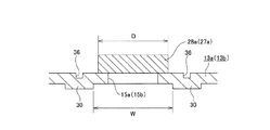
前記支持ブラケット12aは、前記車体10に支持する為の取付板部23aと、この取付板部23aの下面の幅方向に離隔した部分から垂下され、前記変位ブラケット14aを幅方向両側から挟む、互いに平行な1対の支持板部13a、13bとを備える。このうちの取付板部23aは、幅方向両側2箇所位置に、後側縁に開口する状態で、1対の係止切り欠き28a、28aを設け、これら両係止切り欠き28a、28aに、図示しないボルトにより前記車体10に固定された係止カプセル29、29を係止している。これら両係止カプセル29、29を前記両係止切り欠き28a、28aに係止した状態で、これら両係止カプセル29、29と、前記取付板部23aの一部で前記両係止切り欠き28a、28aの両側部分との互いに整合する部分には、それぞれ複数個ずつの小通孔35、35を設けている。そして、合成樹脂、アルミニウム系合金等の裂断し易い材料製の係止ピン(図示省略)を、前記各小通孔35、35に掛け渡す状態で設けている。前記両支持板部13a、13bは、上端縁を前記取付板部23aの下面に溶接等により結合固定されている。これら両支持板部13a、13bの互いに整合する部分には前記両上下方向長孔15a、15bを、前記枢軸11を中心とする円弧状又はこの円弧の接線方向に伸長する直線状で上下方向に伸長する状態で形成している。本例の場合、前記両支持板部13a、13bの内側面のうち、前記両上下方向長孔15a、15bの前後方向両側部分に、幅方向内方に突出する支持ブラケット側凸部30、30を設けている。従って、前記ステアリングホイール1を調節後の位置に保持すべく、前記両支持板部13a、13bにより前記変位ブラケット14aを幅方向両側から押え付けた(挟持した)状態では、前記各支持ブラケット側凸部30、30の先端面が、前記変位ブラケット14aの両側面、即ち、前記両被挟持部22a、22aの外側面と当接する。尚、前記各支持ブラケット側凸部30、30の先端面は、前記ステアリングホイール1を調節後の位置に保持した状態で、これら各先端面と当接する前記両被挟持部22a、22aの外側面と平行な平坦面としている。又、本例の場合、前記各支持ブラケット側凸部30、30の上端縁を、前記両上下方向長孔15a、15bの上端縁よりも上方に位置させると共に、前記各支持ブラケット側凸部30、30の下端縁を、前記両上下方向長孔15a、15bの下端縁よりも下方に位置させている。より具体的には、前記各支持ブラケット側凸部30、30の上端縁の位置を、前記ステアリングホイール1を調節後の位置に保持すべく、前記両支持板部13a、13bにより前記変位ブラケット14aを幅方向両側から押え付けた状態で、前記各支持ブラケット側凸部30、30の上端面と、前記取付板部23aの下面とが当接乃至近接対向する位置としている。尚、前記ステアリングホイール1の位置を調節可能とすべく、前記両支持板部13a、13bにより前記変位ブラケット14aを幅方向両側から押え付けている力を解放した状態では、前記両支持板部13a、13bが、これら両支持板部13a、13b同士の間隔を縮める方向(幅方向)に弾性変形する事を可能にすべく、前記各支持ブラケット側凸部30、30の上端面と、前記取付板部23aの下面との間に隙間を介在させている。この様な支持ブラケット側凸部30、30は、前記両支持板部15a、15bを構成する鋼板等の金属板に、プレスによる張り出し加工を施す事により形成する事ができる。従って、前記両支持板部13a、13bの外側面のうち、内側面に形成した前記各支持ブラケット側凸部30、30と整合する部分には、幅方向内方に凹んだ上下方向凹溝36、36が形成される。
The
前記両上下方向長孔15a、15a及び前記コラム側通孔16aには、前記調節ロッド24aを挿通している。この調節ロッド24aの先端部(図1の左端部)のうちで、前記両支持板部13a、13bのうちの一方(図1〜2の左方)の支持板部13aの外側面から突出した部分に前記調節ナット25aを螺合し、この調節ナット25aを前記調節レバー26aにより回転可能としている。そして、この調節レバー26aを回動してこの調節ナット25aを回転させ、この調節ナット25aの締め付け量(螺合量)を調節する事により、この調節ナット25aと、前記調節ロッド24aの基端部に設けられた頭部27aとの間隔を拡縮可能としている。即ち、本例の場合には、前記調節ナット25a及び前記調節ロッド24aの頭部27aが、特許請求の範囲に記載した1対の押圧部に相当し、前記調節ロッド24a、前記調節ナット25a及び前記調節レバー26aが、同じく拡縮装置に相当する。但し、1対の押圧部同士の間隔を拡縮する為の拡縮装置として、例えば、1対のカム部材のカム面同士の係合により軸方向寸法を拡縮可能としたカム装置を使用する事もできる。即ち、このカム装置を構成する被駆動側カムを、一方の支持板部に形成された上下方向長孔に回転を阻止した状態で係合させると共に、駆動側カムを、調節レバーにより回動可能とする。この場合には、前記被駆動側カムと、調節ロッドの基端部に形成された頭部とが、1対の押圧部に相当する。
The adjusting
又、本例の場合、それぞれが押圧部である、前記調節ナット25aと前記調節ロッド24aの頭部27aとの前後方向に関する幅寸法、即ち、外径Dを、前記各支持ブラケット側凸部30、30のうち、前記両上下方向長孔15a、15aよりも前側部分に形成された(前側の)支持ブラケット側凸部30の後側縁と、同じく後側部分に形成された(後側の)支持ブラケット凸部30の前側縁との間隔Wよりも小さくしている(D<W)。
In the case of this example, the width dimension in the front-rear direction of the adjusting
前記ステアリングホイール1の上下位置又は前後位置を調節する際には、前記調節レバー26aを操作して、前記調節ナット25aと前記調節ロッド24aの頭部27aとの間隔を拡げる。この結果、前記各支持ブラケット側凸部30、30の先端面と前記両被挟持部22a、22aの外側面との当接部の面圧が低下乃至は喪失すると同時に、前記アウタコラム17aの前端部の内径が弾性的に拡がり、このアウタコラム17aの前端部内周面とインナコラム18aの後端部外周面との当接部の面圧が低下乃至は喪失する。この状態で、前記調節ロッド24aが前記両上下方向長孔15a、15aと前記コラム側通孔16aとの内側で変位できる範囲で、前記ステアリングホイール1の上下位置及び前後位置を調節する。
When adjusting the vertical position or the front / rear position of the steering wheel 1, the
前記ステアリングホイール1を所望位置に移動させた後、前記調節レバー26aを操作する事により、前記調節ナット25aと前記調節ロッド24aの頭部27aとの間隔を縮める。この結果、前記各支持ブラケット側凸部30、30の先端面と前記両被挟持部22、22の外側面との当接部の面圧が上昇すると同時に、前記アウタコラム17aの前端部の内径が弾性的に縮まり、このアウタコラム17aの前端部内周面と前記インナコラム18aの後端部外周面との当接部の面圧が上昇して、前記ステアリングホイール1を調節後の位置に保持できる。
After moving the steering wheel 1 to a desired position, the distance between the
尚、本例のチルト式ステアリングコラム装置の場合、衝突事故の際に、運転者の身体が前記ステアリングホイール1にぶつかる、二次衝突が発生し、このステアリングホイール1から前記アウタコラム17aに前方に向いた強い力が加わると、前記両係止カプセル29、29と前記両係止切り欠き28a、28aとの間に掛け渡された係止ピンが裂断する。そして、前記両係止カプセル29、29が前記両係止切り欠き28a、28aから後方に抜け出る(実際には、これら両係止カプセル29、29がそのままの位置に止まったまま、前記支持ブラケット12aが前方に変位する)。そして、前記アウタシャフト19を前記インナシャフト20に対し前方に変位させて、前記ステアリングシャフト5aの全長を収縮しつつ、前記アウタコラム17aが前記インナコラム18aに対し前方に変位して、前記ステアリングコラム6aの全長が収縮する。これにより、前記ステアリングホイール1に衝突した運転者の身体に加わる衝撃を緩和する事ができる。
In the case of the tilt type steering column device of the present example, a secondary collision occurs in which a driver's body hits the steering wheel 1 in the event of a collision, and the steering wheel 1 moves forward to the
上述の様な本例のチルト式ステアリングコラム装置によれば、ステアリングホイールを調節後の位置に保持する力を安定させる事ができる。
即ち、本例の場合、前記支持ブラケット12aを構成する1対の支持板部13a、13bの内側面のうち、前記両上下方向長孔15a、15bの前後方向両側部分に、幅方向内方に突出した支持ブラケット側凸部30、30を形成している。この為、前記ステアリングホイール1を調節後の位置に保持すべく、前記調節ナット25aと前記調節ロッド24aとの間隔を縮めた状態では、前記各支持ブラケット側凸部30、30の先端面が、前記変位ブラケット14aを構成する1対の被挟持部22a、22aの外側面と当接する。従って、本例の場合には、前記ステアリングホイール1を調節後の位置に保持した状態で、互いに当接する、前記各支持ブラケット側凸部30、30の先端面と前記両被挟持部22a、22aの外側面との当接部の面積を、前述の図8〜9に示した従来構造の様に、1対の支持板部13、13の内側面と1対の被挟持部22、22の外側面とを互いに対向する部分のほぼ全面で当接させる構造と比較して小さくできる。この結果、前記各支持ブラケット側凸部30、30の先端面と前記両被挟持部22a、22aの外側面との当接部の面圧を大きくできると共に、当接状態がばらつくのを抑えて、前記ステアリングホイール1を調節後の位置に保持する力を安定させられる。従って、本例の場合には、二次衝突時に運転者の身体に加わる衝撃荷重を緩和する衝撃吸収機構の設計を行い易くできる。
According to the tilt type steering column apparatus of the present example as described above, the force for holding the steering wheel in the adjusted position can be stabilized.
That is, in the case of this example, among the inner side surfaces of the pair of
特に本例の場合には、前記各支持ブラケット側凸部30、30の上端部を、前記両上下方向長孔15a、15bの上端部よりも上方に位置させると共に、前記各支持ブラケット側凸部30、30の下端部を、前記両上下方向長孔15a、15bの下端部よりも下方に位置させている。この為、前記ステアリングホイール1の前後位置にかかわらず、前記各支持ブラケット側凸部30、30の先端面と前記両被挟持部22a、22aの外側面との当接部の当接状態がばらつくのを抑えて、前記ステアリングホイール1を調節後の位置に保持する力を安定させる事ができる。更に本例の場合には、このステアリングホイール1を調節後の位置に保持すべく、前記両支持板部13a、13bにより前記変位ブラケット14aを幅方向両側から押え付けた状態で、前記各支持ブラケット側凸部30、30の上端面と、前記取付板部23aの下面とが当接乃至近接対向する様にしている。従って、前記ステアリングホイール1を調節後の位置に保持した状態で、前記両支持板部13a、13bが前記取付板部23aに対し幅方向に倒れる(傾く)方向の剛性を向上させられる。この結果、前記支持ブラケット12aに対する前記変位ブラケット14aの幅方向に関する支持剛性をより向上させる事ができる。
In particular, in the case of this example, the upper end portions of the respective support bracket side
又、本例の場合、前記各支持ブラケット側凸部30、30を、前記両支持板部15a、15bを構成する金属板にプレス加工による張り出し加工を施す事により設けているので、これら両支持板部15a、15bの左右方向に関する曲げ剛性を向上させる事ができる。この為、前記ステアリングホイール1を調節後の位置に保持した状態での、前記支持ブラケット12aに対する前記変位ブラケット14a(前記アウタコラム17a)の幅方向に関する支持剛性、及び、このアウタコラム17aの振動剛性を向上させられる。この結果、前記ステアリングホイール1の支持剛性感を良好にできて、このステアリングホイール1を操作する運転者の違和感を低減乃至解消できる。
In the case of this example, each of the support bracket side
更に本例の場合には、前記調節ナット25a及び前記調節ロッド24aの頭部27aの外径Dを、前側の支持ブラケット側凸部30の後側縁と後側の支持ブラケット側凸部30の前側縁との間隔Wよりも小さくしている(D<W)。この為、前記ステアリングホイール1を調節後の位置を保持すべく、前記調節レバー26aを操作し前記調節ナット25aの締め付け量を大きくする事に伴って、前記各支持ブラケット側凸部30、30の先端面と前記両被挟持部22、22の外側面との間に作用するモーメントを大きくする事ができる。この結果、前記各支持ブラケット側凸部30、30の先端面と前記両被挟持部22、22の外側面との当接部の当接圧をより大きくする事ができ、前記ステアリングホイール1を調節後の位置に保持する力をより安定させる事ができる。
Furthermore, in the case of this example, the outer diameter D of the
尚、本発明のチルト式ステアリングコラム装置を実施する場合に、アウタコラムの前端部の内径を拡縮可能とする為のスリットを、このアウタコラムの前端部上面に設け、このアウタコラムの前端部上面に変位ブラケットを設ける事もできる。或いは、本発明のチルト式ステアリングコラム装置は、前側のアウタコラムの後端部と、後側のインナコラムの前端部とを軸方向の変位を可能に嵌合させた構造で実施する事もできる。この場合には、変位ブラケットをアウタコラムの後端部の下面又は上面に設ける。又、本発明のチルト式ステアリングコラム装置は、ステアリングホイールの前後位置を調節する為のテレスコピック機構を備えない構造で実施する事もできる。この場合には、変位ブラケットを幅方向に貫通するコラム側通孔を、単なる円孔とする。 When the tilt type steering column device of the present invention is implemented, a slit is provided on the upper surface of the front end portion of the outer column so that the inner diameter of the front end portion of the outer column can be enlarged or reduced. Displacement brackets can also be provided. Alternatively, the tilt type steering column apparatus of the present invention can be implemented with a structure in which the rear end portion of the front outer column and the front end portion of the rear inner column are fitted so as to be capable of axial displacement. . In this case, the displacement bracket is provided on the lower surface or the upper surface of the rear end portion of the outer column. The tilt type steering column apparatus of the present invention can also be implemented with a structure that does not include a telescopic mechanism for adjusting the front-rear position of the steering wheel. In this case, the column side through hole penetrating the displacement bracket in the width direction is simply a circular hole.
[実施の形態の第2例]
図4〜5は、請求項1〜3、5に対応する、本発明の実施の形態の第2例を示している。本例のチルト式ステアリングコラム装置を構成する支持ブラケット12bは、取付板部23bと、締付ブラケット31とを備える。このうちの締付ブラケット31は、鋼板等の金属板を略U字形に曲げ形成して成るもので、1対の支持板部13c、13dと、これら両支持板部13c、13dの上端縁同士を連結する上板部32とを備える。これら両支持板部13c、13dの互いに整合する部分には、上下方向に伸長する状態で、上下方向長孔15c、15dがそれぞれ形成されており、前記両支持板部13c、13dの内側面のうち、これら両上下方向長孔15c、15dの前後両側部分に、幅方向内方に突出する支持ブラケット側凸部30a、30aが設けられている。本例の場合、これら各支持ブラケット側凸部30a、30aの上端縁の位置を、ステアリングホイール1(図8参照)を調節後の位置に保持すべく、前記両支持板部13c、13dにより変位ブラケット14a(図1参照)を幅方向両側から押え付けた状態で、前記各支持ブラケット側凸部30a、30aの上端面と、前記上板部32の下面とが当接乃至近接対向する位置としている。
[Second Example of Embodiment]
FIGS. 4-5 has shown the 2nd example of embodiment of this invention corresponding to Claims 1-3. The
上述の様な本例のチルト式ステアリングコラム装置によれば、前記支持ブラケット12bを構成する部品の点数を少なく抑え、この支持ブラケット12b、延いては、チルト式ステアリングコラム装置全体のコスト低減を図る事ができる。
その他の部分の構成及び作用は、上述した実施の形態の第1例と同様である。
According to the tilt type steering column apparatus of the present example as described above, the number of parts constituting the
The configuration and operation of the other parts are the same as in the first example of the embodiment described above.
[実施の形態の第3例]
図6〜7は、請求項1〜5に対応する、本発明の実施の形態の第3例を示している。本例のチルト式ステアリングコラム装置の変位ブラケット14bを構成する1対の被挟持部22b、22bは、外側面のうちの上端部と下端部とに、幅方向外方に突出する変位ブラケット側凸部33、33を、軸方向に亙って設けている。換言すれば、前記両被挟持部22b、22bの外側面のうち、コラム側通孔16bの開口部を含む上下方向中間部に、幅方向内方に凹んだ凹部34、34を設けている。従って、ステアリングホイール1(図8参照)を調節後の位置に保持すべく、調節ナット25aと調節ロッド24aの頭部27aとの間隔を縮めた状態では、支持ブラケット側凸部30、30の先端面と前記各変位ブラケット側凸部33、33の先端面との当接部の面圧が上昇すると共に、アウタコラム17bの前端部の内径が弾性的に縮まり、このアウタコラム17bの前端部内周面とインナコラム18aの後端部外周面との当接部の面圧が上昇する。即ち、本例の場合には、前記各支持ブラケット側凸部30、30の先端面と前記各変位ブラケット側凸部33、33の先端面とが、前記変位ブラケット14bの幅方向両側で4箇所ずつ、合計8箇所で当接する。この様な変位ブラケット側凸部33、33は、前記アウタコラム17b及び前記変位ブラケット14bを、軽合金をダイキャスト成形する事により一体に形成するのと同時に設ける事ができる。
[Third example of embodiment]
FIGS. 6-7 has shown the 3rd example of embodiment of this invention corresponding to Claims 1-5. The pair of sandwiched
上述の様な本例によれば、前記ステアリングホイール1を調節後の位置に保持した状態で、互いに対向する、1対の支持板部13c、13dの内側面と前記両被挟持部22b、22bの外側面とのうちの当接部の当接面積を、上述した実施の形態の第1〜2例の構造と比較して小さくできる。この結果、前記当接部の面圧をより大きくできると共に、当接状態がばらつくのを抑えて、前記ステアリングホイール1を調節後の位置に保持する力をより安定化させられる。
その他の部分の構成及び作用は、前記実施の形態の第1〜2例と同様である。
According to this example as described above, with the steering wheel 1 held at the adjusted position, the inner surfaces of the pair of
The structure and operation of the other parts are the same as in the first and second examples of the above embodiment.
1 ステアリングホイール
2 ステアリングギヤユニット
3 入力軸
4 タイロッド
5、5a ステアリングシャフト
6、6a ステアリングコラム
7 自在継手
8 中間シャフト
9 自在継手
10 車体
11 枢軸
12、12a、12b 支持ブラケット
13、13a〜13d 支持板部
14、14a、14b 変位ブラケット
15、15a〜15d 上下方向長孔
16、16a、16b コラム側通孔
17、17a、17b アウタコラム
18、18a インナコラム
19 アウタシャフト
20 インナシャフト
21、21a スリット
22、22a、22b 被挟持部
23、23a 取付板部
24、24a 調節ロッド
25、25a 調節ナット
26、26a 調節レバー
27、27a 頭部
28、28a 係止切り欠き
29 係止カプセル
30、30a 支持ブラケット側凸部
31 締付ブラケット
32 上板部
33 変位ブラケット側凸部
34 凹部
35 小通孔
36 上下方向凹溝
DESCRIPTION OF SYMBOLS 1 Steering wheel 2 Steering gear unit 3 Input shaft 4
Claims (5)
このステアリングコラムの一部に固設された変位ブラケットと、
この変位ブラケットに、この変位ブラケットを幅方向に貫通する状態で設けられたコラム側通孔と、
上部に設けられた取付板部及びこの取付板部から下方に垂れ下がった1対の支持板部を有し、これら両支持板部により前記変位ブラケットを幅方向両側から挟んだ状態で、前記取付板部により車体に対し支持される支持ブラケットと、
前記両支持板部の互いに整合する部分に設けられた、上下方向に伸長する1対の上下方向長孔と、
前記コラム側通孔及び前記両上下方向長孔を幅方向に挿通する状態で設けられた調節ロッドと、
この調節ロッドの両端部で、前記両支持板部の外側面から突出した部分に設けられた1対の押圧部と、
これら両押圧部同士の間隔を拡縮する拡縮装置と、
を備えるチルト式ステアリングコラム装置に於いて、
前記両支持板部の内側面のうち、前記両上下方向長孔の前後方向両側の、上下方向に関して少なくともこれら両上下方向長孔の上端部から下端部に掛けての部分と整合する部分に、幅方向内方に突出する支持ブラケット側凸部が、上下方向に連続した状態で形成されている、
事を特徴とするチルト式ステアリングコラム装置。 Inside, a cylindrical steering column for rotatably supporting a steering shaft with a steering wheel supported and fixed at the rear end,
A displacement bracket fixed to a part of the steering column;
In this displacement bracket, a column side through hole provided in a state of penetrating the displacement bracket in the width direction,
A mounting plate provided on the top and a pair of support plates hanging downward from the mounting plate, the mounting plate being sandwiched from both sides in the width direction by the two support plates; A support bracket supported to the vehicle body by the part,
A pair of vertically elongated holes extending in the up-down direction, provided in portions of the support plate portions that are aligned with each other;
An adjustment rod provided in a state of passing through the column side through hole and the two vertical holes in the width direction;
A pair of pressing portions provided at portions projecting from the outer surfaces of the support plate portions at both ends of the adjustment rod;
An expansion / contraction device that expands / contracts the space between the two pressing parts;
In a tilt type steering column device comprising:
Of the inner side surfaces of the two support plate portions, on both sides in the front-rear direction of the two vertical slots, at least in a portion that is aligned with the portion extending from the upper end to the lower end of both the vertical slots in the vertical direction, The support bracket side convex portion protruding inward in the width direction is formed in a state continuous in the vertical direction,
A tilt-type steering column device characterized by this.
前記両押圧部同士の間隔を最も縮めた状態で、前記各支持ブラケット側凸部の上端面を、前記取付板部又はこの取付板部の下面に支持固定された部分の下面に当接乃至近接対向させている、
請求項1に記載したチルト式ステアリングコラム装置。 Each of the support bracket-side convex portions is formed up to a portion located on the upper side of the upper end edges of the upper and lower direction long holes, of the inner side surfaces of the both support plate portions,
With the space between the two pressing portions being most contracted, the upper end surface of each support bracket side convex portion is in contact with or close to the lower surface of the mounting plate portion or the portion fixed to the lower surface of the mounting plate portion. Facing each other,
The tilt type steering column apparatus according to claim 1.
請求項1〜2のうちの何れか1項に記載したチルト式ステアリングコラム装置。 The width dimension in the front-rear direction of the both pressing parts is the same as the rear side edge of the support bracket side convex part formed in the front part of the two vertical bracket elongated holes in the support bracket side convex part. Smaller than the distance from the front edge of the support bracket side convex part formed in the part,
The tilt type steering column apparatus according to any one of claims 1 and 2.
前記両押圧部同士の間隔を最も縮めた状態で、前記各支持ブラケット側凸部の先端面と前記各変位ブラケット側凸部の先端面とを当接させる、
請求項1〜3のうちの何れか1項に記載したチルト式ステアリングコラム装置。 Displacement bracket side convex portions projecting outward in the width direction are formed on both side surfaces of the displacement bracket in a state of being separated in the vertical direction,
In a state where the distance between the two pressing parts is most shortened, the front end surface of each support bracket side convex portion and the front end surface of each displacement bracket side convex portion are brought into contact with each other,
The tilt type steering column apparatus according to any one of claims 1 to 3.
請求項1〜4のうちの何れか1項に記載したチルト式ステアリングコラム装置。 The support bracket is supported with respect to the vehicle body so that it can be detached forward based on an impact load applied in a secondary collision.
The tilt type steering column apparatus according to any one of claims 1 to 4.
Priority Applications (1)
| Application Number | Priority Date | Filing Date | Title |
|---|---|---|---|
| JP2015108696A JP2016222056A (en) | 2015-05-28 | 2015-05-28 | Tilt-type steering column device |
Applications Claiming Priority (1)
| Application Number | Priority Date | Filing Date | Title |
|---|---|---|---|
| JP2015108696A JP2016222056A (en) | 2015-05-28 | 2015-05-28 | Tilt-type steering column device |
Publications (2)
| Publication Number | Publication Date |
|---|---|
| JP2016222056A true JP2016222056A (en) | 2016-12-28 |
| JP2016222056A5 JP2016222056A5 (en) | 2018-06-21 |
Family
ID=57745105
Family Applications (1)
| Application Number | Title | Priority Date | Filing Date |
|---|---|---|---|
| JP2015108696A Pending JP2016222056A (en) | 2015-05-28 | 2015-05-28 | Tilt-type steering column device |
Country Status (1)
| Country | Link |
|---|---|
| JP (1) | JP2016222056A (en) |
Cited By (1)
| Publication number | Priority date | Publication date | Assignee | Title |
|---|---|---|---|---|
| JP2017197178A (en) * | 2016-04-22 | 2017-11-02 | 日本精工株式会社 | Steering device support bracket and steering device |
Citations (3)
| Publication number | Priority date | Publication date | Assignee | Title |
|---|---|---|---|---|
| JP2004359101A (en) * | 2003-06-04 | 2004-12-24 | Nsk Ltd | Steering column device |
| JP2010052725A (en) * | 2008-07-31 | 2010-03-11 | Fuji Kiko Co Ltd | Steering column device |
| JP2010215098A (en) * | 2009-03-17 | 2010-09-30 | Jtekt Corp | Steering device for vehicle |
-
2015
- 2015-05-28 JP JP2015108696A patent/JP2016222056A/en active Pending
Patent Citations (3)
| Publication number | Priority date | Publication date | Assignee | Title |
|---|---|---|---|---|
| JP2004359101A (en) * | 2003-06-04 | 2004-12-24 | Nsk Ltd | Steering column device |
| JP2010052725A (en) * | 2008-07-31 | 2010-03-11 | Fuji Kiko Co Ltd | Steering column device |
| JP2010215098A (en) * | 2009-03-17 | 2010-09-30 | Jtekt Corp | Steering device for vehicle |
Cited By (5)
| Publication number | Priority date | Publication date | Assignee | Title |
|---|---|---|---|---|
| JP2017197178A (en) * | 2016-04-22 | 2017-11-02 | 日本精工株式会社 | Steering device support bracket and steering device |
| WO2018193657A1 (en) * | 2016-04-22 | 2018-10-25 | 日本精工株式会社 | Steering device support bracket and steering device |
| US11148703B2 (en) | 2016-04-22 | 2021-10-19 | Nsk Ltd. | Support bracket for steering apparatus and steering apparatus |
| JP2021175663A (en) * | 2016-04-22 | 2021-11-04 | 日本精工株式会社 | Steering device support bracket and steering device |
| JP7160159B2 (en) | 2016-04-22 | 2022-10-25 | 日本精工株式会社 | Steering device support bracket and steering device |
Similar Documents
| Publication | Publication Date | Title |
|---|---|---|
| JP7160159B2 (en) | Steering device support bracket and steering device | |
| JP6142969B2 (en) | Steering device | |
| JP6142967B2 (en) | Telescopic steering device | |
| JP5609838B2 (en) | Steering column device | |
| JP5962777B2 (en) | Tilt-type steering device | |
| JP2014104871A (en) | Support device for steering column | |
| JP7409317B2 (en) | Outer column and steering device | |
| US11970205B2 (en) | Steering column device | |
| JP2014076805A5 (en) | ||
| JP5975199B1 (en) | Steering device | |
| JP7331865B2 (en) | steering device | |
| JP2016222056A (en) | Tilt-type steering column device | |
| JP2018024400A (en) | Telescopic steering column and steering wheel position adjustment device | |
| JP6759786B2 (en) | Support bracket for steering device and steering device | |
| JP5786760B2 (en) | Telescopic steering device | |
| JP6668619B2 (en) | Telescopic steering column device | |
| JP6384225B2 (en) | Steering column support device | |
| JP2017154558A (en) | Steering device | |
| JP2016084137A (en) | Steering device | |
| JP2016052895A (en) | Steering device | |
| JP2014104786A (en) | Impact absorption-type steering device | |
| JP5408214B2 (en) | Telescopic steering device | |
| JP2014104784A (en) | Support device for steering column | |
| JP2014076806A5 (en) | ||
| JP5708839B2 (en) | Steering column support device |
Legal Events
| Date | Code | Title | Description |
|---|---|---|---|
| A521 | Written amendment |
Free format text: JAPANESE INTERMEDIATE CODE: A523 Effective date: 20180510 |
|
| A621 | Written request for application examination |
Free format text: JAPANESE INTERMEDIATE CODE: A621 Effective date: 20180510 |
|
| A977 | Report on retrieval |
Free format text: JAPANESE INTERMEDIATE CODE: A971007 Effective date: 20190308 |
|
| A131 | Notification of reasons for refusal |
Free format text: JAPANESE INTERMEDIATE CODE: A131 Effective date: 20190319 |
|
| A521 | Written amendment |
Free format text: JAPANESE INTERMEDIATE CODE: A523 Effective date: 20190509 |
|
| A02 | Decision of refusal |
Free format text: JAPANESE INTERMEDIATE CODE: A02 Effective date: 20190820 |