JP5974996B2 - Seedling transplanter - Google Patents
Seedling transplanter Download PDFInfo
- Publication number
- JP5974996B2 JP5974996B2 JP2013175448A JP2013175448A JP5974996B2 JP 5974996 B2 JP5974996 B2 JP 5974996B2 JP 2013175448 A JP2013175448 A JP 2013175448A JP 2013175448 A JP2013175448 A JP 2013175448A JP 5974996 B2 JP5974996 B2 JP 5974996B2
- Authority
- JP
- Japan
- Prior art keywords
- frame
- loading
- seedling
- rotation
- loading device
- Prior art date
- Legal status (The legal status is an assumption and is not a legal conclusion. Google has not performed a legal analysis and makes no representation as to the accuracy of the status listed.)
- Active
Links
Images


Landscapes
- Transplanting Machines (AREA)
Description
この発明は、走行装置を有する機体に予備苗枠を備えた苗移植機に関する。 The present invention relates to a seedling transplanting machine having a spare seedling frame on a machine body having a traveling device.
機体後部に設けた苗タンクに載置した苗床から苗を苗植付部の苗植付け装置で挟み取りながら圃場に苗を植え付ける苗移植機において、苗タンクに載置した苗床が無くなると、上下方向に複数の予備苗載せ台を並べて配置した予備苗枠から苗床を苗タンクに移し替えて圃場への苗の移植を続行する構成が知られている。 In a seedling transplanter that plantes seedlings in a field while pinching seedlings from a seedbed placed in a seedling tank provided at the rear of the aircraft with a seedling planting device in the seedling planting section, when there is no seedbed placed in the seedling tank, the vertical direction A configuration is known in which a seedbed is transferred to a seedling tank from a preliminary seedling frame in which a plurality of preliminary seedling platforms are arranged side by side, and transplantation of seedlings to a field is continued.
特許文献1及び2の苗移植機は、施肥装置で肥料を植え付けた苗に供給しているので、苗の補充作業だけでなく、肥料の補充作業を行う必要がある。このため、予備の苗を予備苗枠に積み込む際、予備の肥料も機体に積み込んでおき、施肥装置に貯留した肥料が減少したとき、圃場端まで戻ることなく肥料の補充を行えるようにしている。
Since the seedling transplanting machines of
しかしながら、苗とは異なり、圃場外から肥料を積み込んで機体に搬送する肥料搬送用の部材は特許文献1及び2の苗移植機には設けられておらず、作業者は苗よりも重い肥料を圃場端から機体まで持ち運ぶ必要があり、作業者の労力がその分増大するという問題がある。
However, unlike seedlings, the fertilizer transport member that loads fertilizer from outside the field and transports it to the machine body is not provided in the seedling transplanters of
特に、圃場端に水路があるときや、圃場端の土質が悪いときなど、圃場端から機体に直接肥料を積み込むことが難しい状況では、作業者は重い肥料を持って圃場内に入り込み、泥土に足を取られる不安定な状態で機体まで移動しなければならない。 Especially in situations where it is difficult to load fertilizer directly into the machine from the field edge, such as when there is a waterway at the field edge or when the soil quality at the field edge is poor, the worker enters the field with heavy fertilizer and enters the mud. You have to move to the aircraft in an unstable state where you can take your feet.
予備苗枠に肥料を積むこともできるが、予備苗枠は苗を積載することを想定したものであるので、重い肥料の積込作業に用いていると、予備苗枠の構成部品にかかる負荷が大きく、通常よりも耐久性の低下が早まり、破損しやすくなる問題がある。 Although it is possible to load fertilizer on the reserve seedling frame, the spare seedling frame is assumed to be loaded with seedlings, so if it is used for loading heavy fertilizer, the load on the components of the reserve seedling frame However, there is a problem that the durability is deteriorated more quickly than usual and is easily damaged.
肥料の量を少なくすれば上記問題は生じないが、その分肥料の積込作業に要する時間が長くなるので、作業能率が大幅に低下する問題がある。
そこで、本発明の課題は、肥料の量が多くても肥料の積込作業を容易に行うことができる作業能率が高い予備苗枠を備えた苗移植機を提供することである。
If the amount of fertilizer is reduced, the above problem does not occur. However, since the time required for loading the fertilizer becomes longer, there is a problem that the work efficiency is greatly reduced.
Then, the subject of this invention is providing the seedling transplanting machine provided with the reserve seedling frame with the high working efficiency which can perform the loading operation | work of a fertilizer easily even if there is much quantity of a fertilizer.
上記本発明の課題を解決するために次のような解決手段を採用する。
請求項1記載の発明は、走行車体(2)の後部に苗植付部(4)及び施肥装置(5)を設け、該走行車体(2)の前部に苗を積載する予備苗枠(38)と作業資材を積載して搬送する積込装置(66)を設け、前記予備苗枠(38)と前記積込装置(66)を各々独立して走行車体(2)に回動自在に設けた苗移植機において、前記予備苗枠(38)と前記積込装置(66)を回動可能な状態と回動が規制された状態に切り替えるロックピン(77a)を設けたことを特徴とする苗移植機である。
In order to solve the above-described problems of the present invention, the following means are adopted.
The invention of
請求項2記載の発明は、前記走行車体(2)の機体前側に前記予備苗枠(38)と積込装置(66)を支持する支持部材(48)を設け、該支持部材(48)の上部に予備苗枠(38)の苗枠回転軸(72)を配置し、前記予備苗枠(38)の下側で、且つ苗枠回転軸(72)の前側の走行車体(2)に積込装置(66)の積込装置回転軸(73)を設け、該積込装置回転軸(73)に回動アーム(74)の基部を回動自在に取り付け、該回動アーム(74)の端部に作業資材を積載する積載部材(76)を設け、前記積込装置(66)は、該積載部材(76)が機体の前側及び側方外側に突出する積込作業位置と、該積載部材(76)が施肥装置(5)に向かって突出する補充作業位置と、該積載部材(76)が予備苗枠(38)の下方に位置する収納位置に切替自在に構成したことを特徴とする請求項1記載の苗移植機である。
According to a second aspect of the invention, the preliminary seedling frame to the fuselage front (38) and loading you supporting device (66) supporting support member (48) provided in said vehicle body (2), the support member (48 upper in the preliminary seedling frame (38) seedling frame axis of rotation of the) (72) arranged at the lower side of the preliminary seedling frame (38), and the front vehicle body of Naewaku rotation axis (72) (2) the loading loading apparatus rotation axis of the device (66) to (73) is provided, fitted with a base of laminate write device rotating shaft rotating arm (73) (74) rotatably, said pivot arm (74 ) the loading member (76) for loading the work material to the end provided of the loading device (66) includes a loading work position in which the carrying member (76) projects into the front and laterally outward of the fuselage, and replenishing working position the stacking member (76) is projecting toward the fertilizing unit (5), the stacking member (76) is below the pre seedling frame (38) A seedling transplantation machine according to
請求項3記載の発明は、前記苗枠回転軸(72)と積込装置回転軸(73)に各々ロック部材(77、78)を設け、該ロック部材(77、78)に少なくとも一つのロック孔を各々形成し、前記ロックピン(77a)を各ロック部材(77、78)のロック孔に差し込むと、前記予備苗枠(38)と前記積込装置(66)の回動が各々規制される構成としたことを特徴とする請求項1または2記載の苗移植機である。
According to a third aspect of the present invention, each of the seedling frame rotation shaft (72) and the loading device rotation shaft (73) is provided with a lock member (77, 78), and the lock member (77, 78) has at least one lock. When each hole is formed and the lock pin (77a) is inserted into the lock hole of each lock member (77, 78), the rotation of the preliminary seedling frame (38) and the loading device (66) is restricted. The seedling transplanter according to
請求項4記載の発明は、前記積載部材(76)の積載位置と非積載位置の切替操作は、前記予備苗枠(38)を苗枠回転軸(72)を中心として機体後ろ側に所定角度回動させると共に、前記積込装置(66)を積込装置回転軸(73)を中心として機体前側に所定角度回動させてから行うことを特徴とする請求項1から3のいずれか1項記載の苗移植機である。 Fourth aspect of the present invention, the loading position and the switching operation of the unladen position location of the stacking member (76) is given to the fuselage behind the preliminary seedling frame (38) around Naewaku rotation axis (72) together to angularly rotate, either claims 1 to 3, characterized in that from by a predetermined angle rotates the fuselage forward the loading device (66) around the loading device rotating shaft (73) 1 The seedling transplanter according to the item .
請求項5記載の発明は、前記走行車体(2)上で、且つ前記施肥装置(5)の前方に作業者が搭乗する操縦席(31)を設け、該操縦席(31)の周辺にフロアステップ(35)を設け、前記積載部材(76)は、作業資材の積込作業位置で機体側方に突出するときは、該積載部材(76)の長手方向と機体左右方向が平行となり、作業資材の積込作業位置で機体前方に突出するとき、及び補充作業位置にあるときには、該積載部材(76)の長手方向と機体前後方向が平行となると共に、補充作業位置では該積載部材(76)の機体内側端部が前記フロアステップ(35)の外側端部と重なることを特徴とする請求項1から4の何れか1項に記載の苗移植機である。
Invention of claim 5, wherein on the vehicle body (2), and provided the cockpit (31) of the operator forwardly to boarding the fertilizing device (5), the floor around the said cockpit (31) step (35) is provided, wherein the stacking member (76), when projected on the body side in the loading work position of the work material, the longitudinal direction and the horizontal direction of the machine body of the laminate placing member (76) is parallel to the working when projecting the aircraft forward in loading work position of the material, and when in the replenishing operation position, together with the longitudinal direction and the vehicle body front-rear direction of the stacking member (76) is parallel, the replenishment working position the stacking member (76 5) The seedling transplanter according to any one of
請求項6記載の発明は、前記走行車体(2)上で、且つ前記操縦席(31)の機体前側に操縦部(33)を設け、該操縦部(33)に燃料タンク(83)を設け、前記積込装置(66)は、前記積載部材(76)が機体前側に突出する位置よりも機体内側方向に回動可能にすると共に、前記積込装置(66)は、操縦部(33)の前方位置まで機体内側方向に回動可能にすることを特徴とする請求項5記載の苗移植機である。 According to a sixth aspect of the invention, on the vehicle body (2), and the provided body front side steering portion of the cockpit (31) (33), a fuel tank (83) provided on the maneuvering section (33) the loading device (66), said with stacking member (76) is rotatable in the inboard direction from the position projecting to the fuselage forward, the loading device (66) is maneuverable part (33) The seedling transplanting machine according to claim 5 , wherein the seedling transplanting machine is configured to be rotatable in an inner side direction of the machine body to a forward position.
請求項7記載の発明は、前記回動アーム(74)は、平面視で「へ」の字形状として屈曲部を形成し、該回動アーム(74)を機体内側方向に回動させると、この屈曲部が前記走行車体(2)に接近し、機体後ろ側方向に回動させると前記屈曲部が走行車体(2)から離間する形状とし、前記回動アーム(74)の端部に回動支軸(68)を接続し、該回動支軸(68)を中心として鉛直方向に回動する回動フレーム(67)を設け、該回動フレーム(67)に積載部材(76)を有する積込装置(66)を載置し、積載部材(76)は、回動フレーム(67)を回動アーム(74)より離れる方向に回動させた際に上方を向いて積載位置になり、回動フレーム(67)を回動アーム(74)に重なる位置に向けて回動させると、下方を向いて非積載位置となる構成とすると共に、前記積載部材(76)は、前記回動フレーム(67)に作業資材を受ける支持枠(69)を備えており、回動フレーム(67)は、内部に空間部を有する長方形とし、支持枠(69)は回動フレーム(67)の長手方向に所定間隔毎に配置した構成からなり、回動フレーム(67)の長手方向の端部に回動支軸(68)を設け、該回動支軸(68)には、回動フレーム(67)の空間部と同じ幅の空間部を各々形成し、複数の支持枠(69)と回動支軸(68)は、回動フレーム(67)の長手方向の幅よりも短い範囲内に配置したことを特徴とする請求項1から6の何れか1項に記載の苗移植機である。
According to a seventh aspect of the present invention, when the turning arm (74) is formed in a bent shape as a letter "H" in a plan view, and the turning arm (74) is turned inward of the body, When the bent portion approaches the traveling vehicle body (2) and is rotated in the rearward direction of the aircraft, the bent portion is separated from the traveling vehicle body (2), and is turned around the end of the rotating arm (74). A movable support shaft (68) is connected, a rotation frame (67) that rotates in the vertical direction about the rotation support shaft (68) is provided, and a stacking member (76) is attached to the rotation frame (67). The loading device (66) is placed, and the stacking member (76) faces upward when the rotating frame (67) is rotated in a direction away from the rotating arm (74). When the rotating frame (67) is rotated toward the position overlapping the rotating arm (74), it faces downward. The stacking member (76) includes a support frame (69) for receiving work material on the rotating frame (67), and the rotating frame (67) is disposed inside. The support frame (69) has a configuration in which the support frame (69) is arranged at predetermined intervals in the longitudinal direction of the rotation frame (67), and a rotation support shaft at the end in the longitudinal direction of the rotation frame (67). (68) is provided, and a space portion having the same width as the space portion of the rotation frame (67) is formed on the rotation support shaft (68), and a plurality of support frames (69) and a rotation support shaft ( 68) is a seedling transplanter according to any one of
請求項1記載の発明によれば、積込装置(66)を用いて肥料容器等の作業資材を苗移植機に積み込むことができるので、重量物である作業資材を積み込む作業に要する労力を軽減することができ、作業者の労力が軽減される。 According to the first aspect of the present invention, since work materials such as fertilizer containers can be loaded into the seedling transplanter using the loading device (66), labor required for loading work materials that are heavy is reduced. Can reduce the labor of the operator.
また、予備苗枠(38)と積込装置(66)を、各々独立して回動可能に走行車体(2)に設けたことにより、予備苗枠(38)に苗を積み込んだ後でも積込装置(66)に作業資材を載置して肥料の積込を行うことができるので、苗や肥料の積込作業の能率が従来技術より向上する。
そして、予備苗枠(38)と積込装置(66)を回動可能な状態と回動が規制された状態に切り替えるロックピン(77a)を設けたことにより、作業資材の積載作業中に積込装置(66)が回動することを防止できるので、積載部材(76)を積込作業位置に戻す作業が不要となり、作業能率が従来よりも向上すると共に、積込中の作業資材が落下することが防止され、地面に落下した作業資材の拾い上げが不要となる。
また、積載部材(76)を収納位置に移動させた状態でロック部材(77、78)同士をロックピン(77a)でロックすると、機体の振動等によって回動アーム(74)が回動して積載部材(76)が積込作業位置や補充作業位置に移動することを防止できるので、積載部材(76)が障害物に接触して破損することが防止される。
Further, preliminary seedlings frame (38) and loading device (66), by digits set to pivotably vehicle body (2) each independently, even after embarked seedlings to preliminary seedling frame (38) product Since the work material can be placed on the loading device (66) and fertilizer can be loaded, the efficiency of loading work of seedlings and fertilizer is improved as compared with the prior art.
Then, by providing a lock pin (77a) for switching the preliminary seedling frame (38) and the loading device (66) between a rotatable state and a state where the rotation is restricted, loading is performed during a work material loading operation. Since the loading device (66) can be prevented from rotating, there is no need to return the stacking member (76) to the loading work position, the work efficiency is improved as compared with the prior art, and the work material being loaded is dropped. This eliminates the need to pick up work materials that have fallen on the ground.
Further, when the lock members (77, 78) are locked with the lock pins (77a) in a state where the stacking member (76) is moved to the storage position, the rotation arm (74) is rotated by vibration of the machine body or the like. Since the loading member (76) can be prevented from moving to the loading work position or the replenishment work position, the loading member (76) is prevented from being damaged due to contact with an obstacle.
請求項2記載の発明によれば、請求項1記載の発明の効果に加えて、予備苗枠(38)と積込装置(66)が共にU字形状の支持部材(48)に支持されることにより、さらに余分なU字形状の支持部材を設ける必要がなくなり、部品点数が削減される。
According to the invention described in
また、積込装置(66)を積込作業位置に配置すると、積載部材(76)が走行車体(2)の前側または走行車体(2)の側方に突出する構成としたことにより、圃場端に走行車体(2)が接近する姿勢になっていても圃場外から肥料や燃料等の作業資材が積み込みやすくなるので、作業能率が向上すると共に、作業者の労力が軽減される。 Further, when the loading device (66) is arranged at the loading work position, the loading member (76) protrudes to the front side of the traveling vehicle body (2) or to the side of the traveling vehicle body (2). Even when the traveling vehicle body (2) is in the approaching position, work materials such as fertilizer and fuel can be easily loaded from outside the field, so that the work efficiency is improved and the labor of the operator is reduced.
そして、積込装置(66)を補充作業位置に移動させると、積載部材(76)と施肥装置(5)、及び苗植付部(4)の間隔が狭くなるので、積載部材(76)に積載した作業資材の積込作業に要する時間と労力が小さくなり、作業能率が向上する。 Then, when the loading device (66) is moved to the replenishment work position, the interval between the loading member (76), the fertilizer application device (5), and the seedling planting part (4) becomes narrow, so the loading member (76) The time and labor required for loading the loaded work material is reduced, and the work efficiency is improved.
さらに、積込装置(66)を収納位置に移動させると、積込装置(66)が走行車体(2)の前方や側方に突出しないので積込装置(66)が壁等の障害物に接触して破損することが防止されると共に、走行車体(2)から作業者が乗り降りする部分を塞がないので、作業者が走行車体(2)から乗り降りする際に積込装置(66)を移動させる作業が不要となり、作業能率が向上する。 Further, when the loading device (66) is moved to the storage position, the loading device (66) does not protrude forward or sideward of the traveling vehicle body (2), so that the loading device (66) becomes an obstacle such as a wall. Since it is prevented from being damaged by contact, and the portion where the operator gets on and off the traveling vehicle body (2) is not blocked, the loading device (66) is installed when the operator gets on and off the traveling vehicle body (2). The work to be moved becomes unnecessary, and the work efficiency is improved.
請求項3記載の発明によれば、請求項1または2記載の発明の効果に加えて、予備苗枠(38)と積込装置(66)を回動可能な状態と回動が規制された状態に切り替えるロックピン(77a)を設けたことにより、作業資材の積載作業中に積込装置(66)が回動することを防止できるので、積載部材(76)を積込作業位置に戻す作業が不要となり、作業能率が従来よりも向上すると共に、積込中の作業資材が落下することが防止され、地面に落下した作業資材の拾い上げが不要となる。
また、積載部材(76)を収納位置に移動させた状態でロック部材(77、78)同士をロックピン(77a)でロックすると、機体の振動等によって回動アーム(74)が回動して積載部材(76)が積込作業位置や補充作業位置に移動することを防止できるので、積載部材(76)が障害物に接触して破損することが防止される。
According to the invention described in
Further, when the lock members (77, 78) are locked with the lock pins (77a) in a state where the stacking member (76) is moved to the storage position, the rotation arm (74) is rotated by vibration of the machine body or the like. Since the loading member (76) can be prevented from moving to the loading work position or the replenishment work position, the loading member (76) is prevented from being damaged due to contact with an obstacle.
請求項4記載の発明によれば、請求項1から3のいずれか1項に記載の発明の効果に加えて、予備苗枠(38)を機体後ろ側に所定角度回動させ、積込装置(66)を機体前側に所定角度回動させてから積載部材(76)を操作することにより、予備苗枠(38)と積込装置(66)が干渉し合うことを防止できるので、機体が傷付くことが防止される。
また、積込装置(66)の回動軌跡上に予備苗枠(38)が位置することにより、積込装置(66)を移動させたい位置まで動かせず、作業資材の積込作業能率が低下することが防止される。
According to the fourth aspect of the present invention, in addition to the effect of the invention according to any one of
Further , since the preliminary seedling frame (38) is positioned on the rotation trajectory of the loading device (66), the loading device (66) cannot be moved to the position where it is desired to move, and the loading efficiency of the work material can be increased. Decrease is prevented.
そして、積載部材(76)を非積載状態とし、予備苗枠(38)を回動させてから積載部材(76)を収納位置に移動させると、予備苗枠(38)を積載部材(76)に干渉させることで積載部材(76)の回動を抑えることができるので、回動アーム(74)が回動することがあっても積込装置(66)が大きく機体前方や側方に突出することが防止され、障害物に接触して破損することが防止される。 Then, when the stacking member (76) is brought into a non-stacked state, the preliminary seedling frame (38) is rotated, and then the stacking member (76) is moved to the storage position, the preliminary seedling frame (38) is moved to the stacking member (76). Since the rotation of the loading member (76) can be suppressed by interfering with the load, the loading device (66) is large and protrudes forward or sideward even if the rotation arm (74) rotates. And is prevented from being damaged by contact with an obstacle.
さらに、積載部材(76)を積載状態とし、予備苗枠(38)を回動させると予備苗枠(38)が回動フレーム(67)の上下回動を抑えることにより、走行車体(2)の振動等で回動フレーム(67)が回動することを防止できるので、積載された作業資材が落下することが防止され、積込装置(66)から落下した作業資材(36)の回収に要する労力が軽減される。 Further, when the loading member (76) is placed in the loaded state and the preliminary seedling frame (38) is rotated, the preliminary seedling frame (38) suppresses the vertical rotation of the rotating frame (67), thereby causing the traveling vehicle body (2). since it is possible to prevent the pivoting frame in a vibration (67) is rotated, it is prevented that the stacked working materials falls, the recovery of working materials dropped from loading device (66) (36) The labor required is reduced.
請求項5記載の発明によれば、請求項1から4の何れか1項に記載の発明の効果に加えて、積載部材(76)は、作業資材の積込作業位置で機体側方に突出するときは、その長手方向と機体左右方向が平行となり、作業資材の積込作業位置で機体前方に突出する(この位置は補充作業位置でもある)ときは、積載部材(76)の長手方向と機体前後方向が平行となることにより、積載部材(76)の突出量を大きくすることができるので、機外から作業資材の積込や、積載部材(76)から施肥装置(5)や苗植付部(4)への作業資材の補充作業が容易になるので、作業能率が向上すると共に、作業者の労力が軽減される。
According to the invention described in claim 5, in addition to the effect of the invention described in any one of
また、積載部材(76)は、補充作業位置では積載部材(76)の機体内側端部がフロアステップ(35)の外側端部と重なり合うことにより、走行車体(2)に搭乗する作業者がフロアステップ(35)の外側端部を把握しやすくなり、移動に気を使い過ぎることがなく、作業者の負担が軽減される。 In addition, the loading member (76) is configured such that, at the replenishment work position, the inner end of the body of the loading member (76) overlaps with the outer end of the floor step (35), so that an operator who rides on the traveling vehicle body (2) can move to the floor. It becomes easy to grasp the outer end portion of step (35), and the operator's burden is reduced without excessive use of movement.
また、請求項6記載の発明によれば、請求項5に記載の発明の効果に加えて、積込装置(66)を機体内側方向に回動させると、ハンドル(34)やボンネット(32)等からなる操縦部(33)の前に積載部材(76)が位置することにより、燃料入りのポリタンク等の作業資材を燃料タンク(83)に近付けることができるので、作業者が作業資材を操縦部(33)の前まで運ぶ必要がなく、作業者の労力が軽減される。 According to the sixth aspect of the invention, in addition to the effect of the fifth aspect of the invention, when the loading device (66) is rotated inward of the fuselage, the handle (34) and the bonnet (32) Since the loading member (76) is positioned in front of the control unit (33) composed of, etc., the work material such as a fuel-filled polytank can be brought close to the fuel tank (83). It is not necessary to carry it to the front of the part (33), and the labor of the operator is reduced.
また、積載部材(76)と操縦部(33)に設ける燃料タンク(83)の間隔を短くすることができるので、積載部材(76)に積載した作業資材から燃料タンク(83)に燃料を送り込みやすくなり、作業能率が向上する。 Further, since the distance between the loading member (76) and the fuel tank (83) provided in the control section (33) can be shortened, the fuel is sent from the work material loaded on the loading member (76) to the fuel tank (83). becomes easier, the working efficiency is above direction.
請求項7記載の発明によれば、請求項1から6の何れか1項に記載の発明の効果に加えて、回動フレーム(67)を、回動支軸(68)を中心として回動アーム(74)より離れる方向に向けて回動させると上方を向いて積載位置になり、積載部材(76)を回動アーム(74)に重なる位置に向けて回動させると、積載部材(76)が上方を向いて積載位置となることにより、積載部材(76)の突出量を大きくすることができるので、作業資材の積込作業能率が一層向上すると共に、積載部材(76)から施肥装置(5)や苗植付部(4)への作業資材の移動に要する時間と労力が軽減される。
また、回動支軸(68)を中心として回動フレーム(67)を回動アーム(74)に重なる位置に向けて回動させると積載部材(76)が下方を向いて非積載位置となることにより、予備苗枠(38)と積載部材(76)の上下間隔を広くすることができるので、積載部材(76)が予備苗枠(38)に干渉することが防止され、積込装置(66)が予備苗枠(38)からはみ出す範囲が抑えられ、積込装置(66)が障害物に接触して破損することが防止される。
また、積込装置(66)を機体内側方向に回動させると、回動アーム(74)の屈曲部が走行車体(2)に接近することにより、回動アーム(74)による走行車体(2)の前側の作業空間の占有面積を小さくすることができるので、作業者が走行車体に近寄りやすくなり、燃料や肥料等の作業資材(36)の積込作業能率が向上する。
そして、積込装置(66)を機体後ろ側方向に回動させると、回動アーム(74)の屈曲部が走行車体(2)から離間することにより、回動アーム(74)が苗枠回転軸(72)に接触するまでの回動量が大きくなるので、積載部材(76)を走行車体(2)に近づけることができ、肥料等の補充作業を安定した位置で行え、補充作業の能率が向上する。
さらに、複数の支持枠(69)を回動フレーム(67)に所定間隔毎に配置して積載部材(76)を構成したことにより、作業者は積載した作業資材を支持枠(69)同士の空間部に手を入れて積み降ろしすることができるので、作業資材の積み降ろし作業の能率が向上する。
According to the invention described in
Further, when the rotation frame (67) is rotated about the rotation support shaft (68) toward the position overlapping the rotation arm (74), the stacking member (76) is directed downward to the non-loading position. As a result, the vertical gap between the preliminary seedling frame (38) and the stacking member (76) can be widened, so that the stacking member (76) is prevented from interfering with the preliminary seedling frame (38), and the loading device ( 66) is prevented from protruding from the reserve seedling frame (38), and the loading device (66) is prevented from being damaged due to contact with an obstacle.
Further, when the loading device (66) is rotated inward of the machine body, the bent portion of the rotating arm (74) approaches the traveling vehicle body (2), whereby the traveling vehicle body (2 by the rotating arm (74) is obtained. ) Can be reduced, the operator can easily approach the traveling vehicle body, and the work efficiency of loading work materials (36) such as fuel and fertilizer is improved.
Then, when the loading device (66) is rotated in the rear direction of the machine body, the bent portion of the rotating arm (74) is separated from the traveling vehicle body (2), so that the rotating arm (74) rotates the seedling frame. Since the amount of rotation until it comes into contact with the shaft (72) is increased, the stacking member (76) can be brought close to the traveling vehicle body (2), and replenishment work such as fertilizer can be performed at a stable position, and the efficiency of the replenishment work is improved. improves.
Furthermore, by arranging a plurality of support frames (69) on the rotating frame (67) at predetermined intervals to form the stacking member (76), the operator can place the loaded work material between the support frames (69). Since it is possible to load and unload the space part, the efficiency of the work material loading and unloading work is improved.
以下、図面に基づき、本発明の好ましい実施の形態について説明する。
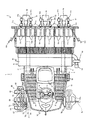
図1及び図2は作業車両の一実施例である乗用型苗移植機の左側面図及び平面図であり、図3には図1の乗用型苗移植機の右前方側面図を示し、図4には図1の乗用型苗移植機の前方要部平面図を示し、図5には図1の乗用型苗移植機の要部正面図を示す。
Hereinafter, preferred embodiments of the present invention will be described with reference to the drawings.
1 and 2 are a left side view and a plan view of a riding seedling transplanter as an embodiment of a work vehicle, and FIG. 3 is a right front side view of the riding seedling transplanter of FIG. 4 shows a front plan view of the main part of the riding seedling transplanter of FIG. 1, and FIG. 5 shows a front view of the main part of the riding seedling transplanter of FIG.
なお、本実施例では乗用型苗移植機の操縦席で運転する者が前進する方向に向かって左右方向をそれぞれ左、右とし、前進する方向を前、後退する方向を後ろという。
この乗用型苗移植機1には、走行車体2の後ろ側に昇降リンク装置3を介して作業部としての苗植付部4が昇降可能に装着されている。
In the present embodiment, the left and right directions are referred to as left and right, respectively, in the direction in which the person driving at the cockpit of the riding seedling transplanter moves forward, the forward direction is referred to as the front, and the backward direction is referred to as the rear.
A
乗用型苗移植機1は、駆動輪である左右一対の前輪10,10及び左右一対の後輪11,11を備えた四輪駆動車両であって、機体の前部にミッションケース12が配置され、そのミッションケース12の左右側方に前輪ファイナルケース13,13が設けられ、該左右前輪ファイナルケース13,13の操向方向を変更可能な各々の前輪支持部から外向きに突出する左右前輪車軸10a,10aに左右前輪10,10が各々取り付けられている。
The riding
また、走行車体2の後ろ側に昇降リンク装置3を介して苗植付部4が昇降可能に装着され、走行車体2の後部上側に施肥装置5の本体部分が設けられている。
さらに、ミッションケース12の背面部にメインフレーム15の前端部が固着されており、そのメインフレーム15の後端左右中央部に前後水平に設けた後輪ローリング軸(図示せず)を支点にして後輪ケース18,18がローリング自在に支持され、その後輪ケース18,18から外向きに突出する後輪車軸11a,11aに後輪11,11が取り付けられている。
In addition, a
Further, the front end portion of the
エンジン20はメインフレーム15の上に搭載されており、該エンジン20の回転動力が、静油圧式無段変速装置(HST)23などを介してミッションケース12に伝達される。ミッションケース12に伝達された回転動力は、該ミッションケース12内の主変速装置及び副変速装置により変速された後、走行動力と外部取り出し軸に分離して取り出される。
The
エンジン20からHST23を介して伝達される走行動力は、一部が前輪ファイナルケース13,13を経て前輪10,10を駆動すると共に、残りが後輪ケース18,18を経て後輪11,11を駆動する。また、外部取出動力は、走行車体2の後部に設けた植付クラッチケース(図示せず)に伝達され、それから植付伝動軸26によって苗植付部4へ伝動される。
A part of the driving power transmitted from the
エンジン20の上部には操縦席31が設置された操縦部33があり、該操縦部33にはHST23を操作して走行車体2の前後進、停止及び走行速度を変速する走行操作レバー(HST操作レバー)17と走行車体2の走行速度を複数段に変速するための副変速レバー16が配置されている。
There is a
操縦席31の前方には各種操作機構を内蔵するフロントカバー32があり、その上方に前輪10,10を操向操作するハンドル34が設けられている。フロントカバー32の下端左右両側は水平状のフロアステップ35になっている。フロアステップ35は多数の穴が設けられており(図2参照)、該ステップ35を歩く作業者の靴についた泥が圃場に落下するようになっている。フロアステップ35上の後部は、後輪フェンダを兼ねるリアステップ36となっている。
A
また、走行車体2の前部左右両側には、補給用の苗を載せておく予備苗枠38(予備苗載せ台38a,38b,38c)を設けている。左側の予備苗枠38Lは図1に示すように前後及び上下に移動式の苗枠38とし、右側の予備苗枠38Rは苗枠回転軸72を中心に回動する苗枠である。
Further, on both the left and right sides of the front portion of the traveling
移動式の予備苗枠38Lは機体の一部である正面視U字状の予備苗枠支持フレーム48の左側先端部に支持された支持支柱80Lに第3予備苗枠38cLと第2、第3移動リンク部材39b,39cを取り付け、第2、第3移動リンク部材39b,39cで第2予備苗枠38bLを支持し、さらに第1、第2移動リンク部材39a,39bと第2予備苗枠38bLで第1予備苗枠38aLを支持している。第1、第2、第3移動リンク部材39a,39b,39cは支持支柱80Lに取り付けられた第2移動リンク部材39bの回動中心軸に設けられた図示しないモータを有する駆動装置70で回動して、第1予備苗枠38aL、第2予備苗枠38bL、第3予備苗枠38cLを前後ほぼ同一平面状に展開する展開状態と上下に段状に配置される積層状態に変更することができる。
The movable
第1予備苗枠38aL、第2予備苗枠38bL、第3予備苗枠38cLの底面側には図示しないが4輪からなるローラが設けられており、第1予備苗枠38aL、第2予備苗枠38bL、第3予備苗枠38cLを展開状態にしたときに、該ローラはローラ回転用モータ82a,82b,82cで駆動可能であり、走行車体2の前方から苗を補充する際にこれらのローラを駆動することで、作業者は苗を第1予備苗枠38aLから第3予備苗枠38cLまで手で押し込む必要が無くなり、作業者の労力が軽減されると共に、苗を押す際に作業者が苗を掴んだときや、第1予備苗枠38aL,第2予備苗枠38bL、第3予備苗枠38cLの左右の側壁部分に接触したときに、苗が潰されることが防止されるという利点がある。
Although not shown, a roller having four wheels is provided on the bottom side of the first preliminary seedling frame 38aL, the second preliminary seedling frame 38bL, and the third preliminary seedling frame 38cL, and the first preliminary seedling frame 38aL and the second preliminary seedling frame 38aL are provided. When the frame 38bL and the third preliminary seedling frame 38cL are in the unfolded state, the rollers can be driven by
右側の予備苗枠38Rは苗枠回転軸72を中心に回動する苗枠38とし、U字状支持フレーム48の右側先端部に並列状に立設された一対の支持支柱80Rに第3予備苗枠38aR、第2予備苗枠38bR、第3予備苗枠38cRが取り付けられている。一方の支持支柱80Rの下端部が苗枠回転軸72により、予備苗枠支持フレーム48の右側先端部に水平方向に回転自在に支持されている。なお、並列状に立設された一対の支持支柱80Rの基部は橋渡し部材79で支持されている。
The right
また、第3予備苗枠38cRの下方には、積込装置66が設けられており、該積込装置66は積込装置回転軸73で予備苗枠支持フレーム48の右側先端部に水平方向に回転自在に支持されている。
In addition, a
前記積込装置回転軸73は苗枠回転軸72の直ぐ前側にあり、積込装置回転軸73には「ヘ」字状の回動アーム74の一端が接続しており、また、「ヘ」字状の回動アーム74の他端が回動支軸68の中央部に接続している。回動支軸68の両端は平面視で矩形状の回動フレーム67に回動自在に接続しており、矩形状の回動フレーム67のなす平面上に積込装置が載置されるように両者が固着している。
The loading
従って、積込装置66は、積込装置回転軸73を中心として回動アーム74の水平方向への回転に応じて図4に示すように苗移植機の右前方で走行車体2の周りを約270度の範囲で回転することができる。
Therefore, the
また、図5の苗移植機の右前方部の平面図に示すように、操縦席33の右横位置で、走行車体2に隣接させて積込装置66を配置して、各種の作業用資材を載置することができるので操縦者には便利である。
Further, as shown in the plan view of the right front portion of the seedling transplanter in FIG. 5, a
さらに、積込装置66は回動支軸68を支点とする回動フレーム67の回動に応じて上下方向に回動できる。従って、積込装置66は、図4に示す実線位置で積み込み作業ができる展開位置となり、図2に示す実線位置で収納位置となる。前記収納位置で積込装置66は、ほぼ同一面積の予備苗枠38の下側で天地が逆転することになる。
Further, the
肥料袋などの重い作業用資材を積込装置66に積み込む場合、あるいは圃場に移動させる場合に、積込装置66が図3の点線位置(=図4のステップ35に隣接した点線位置)にあると、積込装置66がステップ35の上方位置で平面視で一部重なることになるので、操縦者がステップ35から足を踏み外すことなく、作業をしやすくなり、また圃場で作業をする補助者も、エンジンカバーとほぼ同じ高さ位置にある積込装置66上の作業用資材を扱い易くなる。
When a heavy work material such as a fertilizer bag is loaded on the
また、図4に示す実線位置(走行車体2の右側面に積込装置66の長手方向が直交する位置)に積込装置66がある場合は、「ヘ」字状の回動アーム74は走行車体2の前端部と、予備苗枠38Rの前端部に比べて少し前側に位置する。この位置は、作業時に畦と確実に重なる位置であるので、作業者は足場の不安定な圃場内に入ることなく苗や肥料、燃料入りのポリタンク等の作業資材を積み込むことができ、積込装置66への作業資材の出し入れ作業が容易になる。
Further, when the
また、図6に示す予備苗枠38Rと積込装置66のように、予備苗枠38Rを矢印X方向に機体内側に90度回転させると共に積込装置66を回動支軸68を支点として回動フレーム67を下側から矢印Y方向に機体2側に180度回動させると、予備苗枠38と積込装置66が重ならなくなる。また、図4の破線で示すステップ35に沿った位置にある積込装置66を90度回転させて図4の実線位置に移動させると、積込装置66の載置面側が上側に向いているので、圃場の作業者が積込装置66の載置面上にある肥料袋などの作業資材を持ち上げ易くなり、作業能率が向上する。
Further, like the
こうして、走行車体2の左右にある予備苗枠38に苗が載置されていても、さらに積込装置66を利用して苗床だけでなく肥料容器、燃料入りのポリタンクなどの作業資材を積み込むことができる。また、作業の必要に応じて回転軸72、73をそれぞれ支点として予備苗枠38、積込装置66を回動させることができる。
In this way, even if seedlings are placed on the spare seedling frames 38 on the left and right of the traveling
図4の矢印Sで示す位置に積込装置66を移動させると、積込装置66と走行車体2の前側に内装される燃料タンク83との間隔を狭めることができる。これにより、図7に示すように、積込装置66上に燃料入りの携行缶84を載置し、該燃料タンク83と積込装置66上の携行缶84をホース85で接続し、携行缶84から燃料を燃料タンク83に供給することができる。
When the
このとき、積込装置66と燃料タンク83の間隔が狭いために、作業者は携行缶84を片手で傾け、もう片方の手でホース85を支持して燃料タンク83に燃料を供給することができるので、従来のように携行缶84を持ち上げて燃料の補充をする必要がなく、作業者の労力が軽減されると共に、ホース85が外れて燃料が圃場にこぼれることが防止される。
At this time, since the gap between the
図8に示す位置にある予備苗枠38Rと収納位置にある積込装置66について述べる。
苗枠回転軸72と積込装置回転軸73にそれぞれロック孔を有する円盤状のロック部材77、78を設けている。該ロック部材77、78のロック孔を合わせ、ロックピン77aを該ロック孔に挿入してロック部材77、78同士を連結すると、予備苗枠38Rと積込装置66との回動が規制されることにより、作業資材の積載作業中に積込装置66が回動することを防止できるので、積載部材76を積込作業位置に戻す作業が不要となり、作業能率が従来より向上すると共に、積込中の作業資材が落下することが防止され、地面に落下した作業資材の拾い上げが不要となる。
The
Disk-shaped
また、積載部材76を収納位置に移動させた状態で、ロック部材77、78同士をロックすると、機体の振動等によって回動アーム74が回動して積載部材76が積込作業位置や補充作業位置に移動することを防止できるので、積載部材76が障害物に接触して破損することが防止される。
In addition, when the
図9には、積込装置66に取り付ける積載部材76の斜視図(図9(a))と平面図(図9(b))を示す。積載部材76は回動フレーム67と該回動フレーム67に接続した複数の支持枠69からなる。回動フレーム67は、内部に間隙を有する長方形(ループ状)とし、複数の支持枠69は折り曲げた回動フレーム67の長手方向に所定間隔毎に溶接接続している。
FIG. 9 shows a perspective view (FIG. 9A) and a plan view (FIG. 9B) of the stacking
回動フレーム67の長手方向の両端部を橋渡しする回動支軸68には、回動フレーム67の空間部と同じ幅の空間部を各々形成し、複数の支持枠69と回動支軸68は、回動フレーム67の長手方向の幅よりも短い範囲内に配置した作業資材を受ける構成としている。
A space portion having the same width as the space portion of the
こうして、複数の支持枠69を回動フレーム67に所定間隔毎に配置して積載部材76を構成したことにより、作業者は積載した作業資材を支持枠69同士の空間部に手を入れて積み降ろしすることができるので、作業資材の積み降ろし作業の能率が向上する。
In this way, the stacking
回動フレーム67の長手方向の一端部は積込装置66を動かす際に、持ち手とすることができる。この持ち手を把持しながら図4に示すように積込装置66を水平移動することができ、さらに積込装置66の収納時にもこの部分を把持しながら、積込装置66を収納位置に回転させることができるので、作業能率が向上する。
One end of the
図10の苗移植機の前方の側面図に示すように、積込装置回転軸73を中心に積込装置66を回転させた後に積込装置66がA位置にあっても、B位置にあっても、積込装置回転軸73を傾斜(水平に対して5〜10度程度)状態の底とするように回動アーム74に接続している。
As shown in the side view in front of the seedling transplanter in FIG. 10, even if the
そのため、ステップ35上でオペレータが肥料を補給する際に、オペレータが積込装置66に肥料などを補給する際に、積込装置66の側方より少し前方の位置に立った状態でも、またオペレータが積込装置66の側方で片足をステップ35後方の高い位置に掛けた状態でも、積込装置66の後方が上がっているため、楽な姿勢で肥料袋などを持ち上げることができる。またボンネット32の前で積込装置66上に載せた携行缶84から燃料を苗移植機へ補給する際にも積込装置66の後方が上がっているため、燃料補給をし易い。
Therefore, when the operator replenishes the fertilizer on the
次に、図11を用いて本実施例の左側予備苗枠38Lを用いて展開状態と積載状態の切り替えのための制御フローチャートについて説明する。なお、図11で左側のフローチャートは電気回路の動きを示すステップであり、右側のフローチャートは、実際のモータの作動で予備苗枠38Lが積載状態から展開状態に切り替わると、苗送りローラ82a、82b、82cが回転して補充された苗を機体後方(苗植付部側)に搬送する作業を示すステップである。
Next, a control flowchart for switching between the unfolded state and the loaded state using the left-side
まず、積載状態にある予備苗枠38a、38b、38c上の全てに苗が載置されていることを予備苗枠38a、38b、38c上のすべてに設置している図示しない苗残量センサが検知すると、切替駆動装置70が作動して、予備苗枠38Lを展開状態にする。予備苗枠38Lを前後方向のほぼ同一平面上に並べて展開状態にすることを苗レール変形と呼ぶこととし、予備苗枠38Lを上下3段に配置して積層状態にすることを苗枠変形と呼ぶこととにする。
First, a seedling remaining amount sensor (not shown) installed on all the spare seedling frames 38a, 38b, and 38c indicates that seedlings are placed on all of the spare seedling frames 38a, 38b, and 38c in the loaded state. When detected, the switching
苗レール変形にするためには苗レール切替用の図示しないモータ(切替駆動装置70内にある)を作動させる(S3)。次いで、S4で苗レール変形をリミットスイッチが検知すると前記苗レール切替モータが停止する。また、図示しないリミットスイッチで予備苗枠38Lが展開状態になったことを検知すると、苗レールのローラ回転用モータ82(図5)が作動する(S5)。次いで図示しない苗残量センサが苗レール上の苗が全てなくなったことを検出する(S6)と、苗レールのローラ回転用モータ82が停止する(S7)。次に苗レール変形モータが作動して(S8)、予備苗枠38Lを積載状態に変える作動が行われ、予備苗枠変形をリミットスイッチが検知すると予備苗枠は積載状態となる(S9)。
In order to change the seedling rail, a motor (not shown) for switching the seedling rail (in the switching drive device 70) is operated (S3). Next, when the limit switch detects the deformation of the seedling rail in S4, the seedling rail switching motor stops. When the limit switch (not shown) detects that the
次に、苗移植機のその他の構成の概略の説明をする。
図1に示すように、苗植付部4の昇降リンク装置3は平行リンク構成であって、1本の上リンク40と左右一対の下リンク41,41を備えている。これらリンク40,41,41は、その基部側がメインフレーム15の後端部に立設した背面視門型のリンクベースフレーム42に回動自在に取り付けられ、その先端側に縦リンク43が連結されている。
Next, an outline of the other configuration of the seedling transplanter will be described.
As shown in FIG. 1, the
そして、縦リンク43の下端部に苗植付部4に回転自在に支承された連結軸44が挿入連結され、連結軸44を中心として苗植付部4がローリング自在に連結されている。メインフレーム15に固着した支持部材と上リンク40に一体形成したスイングアーム(図示せず)の先端部との間に昇降用油圧シリンダ46が設けられており、該シリンダ46を油圧で伸縮させることにより、上リンク40が上下に回動し、苗植付部4がほぼ一定姿勢のまま昇降する。
And the connecting
また、苗載せ台51は苗植付部4の全体を支持する左右方向と上下方向に幅一杯の矩形の支持フレーム65bと支持ローラ65aからなる枠体構造物65をレール状にして左右方向にスライドする構成である。
In addition, the
苗植付部4は6条植の構成で、フレームを兼ねる伝動ケース50と、マット苗を載せて左右往復動し、苗を一株分ずつ各条の苗取出口51a,…に供給すると共に横一列分の苗を全て苗取出口51a,…に供給する苗送りベルト51b,…により苗を下方に移送する苗載台51と、苗取出口51a,…に供給された苗を圃場に植え付ける苗植付爪52aを備えた苗植付装置52,…と、次工程における機体の進路を表土面に線引きする左右一対の線引きマーカ184,184等を備えている。
The
なお、機体の前部左右両側には、隣接条に植え付けられた苗の上方に位置し続け、作業者が機体を走行させる目安とする左右一対のサイドマーカ75,75を備えている。前記線引きマーカ184,184は圃場面を削って直進走行の目安となる線を形成するものであるが、土質が柔らかいと、溝が時間の経過によって自然に埋まったり、線引きマーカ184,184が巻き上げた泥で溝が見えなくなったりすることがある。このときは、サイドマーカ75,75と既に植えた隣接条の苗を合わせながら走行すると、隣接条の苗の植え付けに合わせた苗の植え付けが可能となるので、苗の植え付け方向が乱れることがなく、植付精度が向上する。なお、線引きサイドマーカ75は予備苗枠支持フレーム48に支持されて、機体両側に設けられている。
Note that a pair of left and
また、苗植付部4の下部には中央にセンターフロート55、その左右両側にサイドフロート56,56がそれぞれ設けられている。
これらフロート55,56,56を、圃場の泥面に接地させた状態で機体を進行させると、フロート55,56,56が泥面を整地しつつ滑走し、その整地跡に苗植付装置52,…により苗が植え付けられる。各フロート55,56,56は圃場表土面の凹凸に応じて前端側が上下動するように回動自在に取り付けられており、植付作業時にはセンターフロート55の前部の上下動がフロート傾斜角センサ(図示せず)により検出され、その検出結果に応じ、前記昇降用油圧シリンダ46を制御する油圧バルブを切り替えて苗植付部4を昇降させることにより、苗の植付深さを常に一定に維持する。
Further, a
When these floats 55, 56, 56 are grounded on the mud surface of the field, the aircraft moves forward, and the
苗植付部4には整地装置の一例であるロータ27(27a,27b)が取り付けられている。整地ロータ27a,27bの後ろ上方には、ロータカバー28を設け、フロート55,56上に泥がかからないようにしている。
A rotor 27 (27a, 27b) which is an example of a leveling device is attached to the
施肥装置5は、肥料ホッパ60に貯留されている粒状の肥料を繰出部61,…によって一定量ずつ繰り出し、その肥料を施肥ホース62,…でフロート55,56,56の左右両側に取り付けた施肥ガイド(図示せず)まで導き、施肥ガイドの前側に設けた作溝体64(図1),…によって苗植付条の側部近傍に形成される施肥溝内に落とし込むようになっている。ブロア用電動モータ53で駆動するブロア58で発生させたエアが左右方向に長いエアチャンバ59を経由して施肥ホース62に吹き込まれ、施肥ホース62内の肥料を風圧で強制的に搬送するようになっている。
The fertilizer applicator 5 feeds the granular fertilizer stored in the
操縦席31の前方下部に設けられた副変速レバー16はレバーガイド(図示せず)に沿って回動操作することにより、図示しない副変速装置が「路上走行速」、「中立」、「植付速」のいずれかに手動で切り換わるように構成されている。そして、副変速レバー16の基部側に設けた副変速レバーセンサ(レバー16の操作角度を検出するポテンショメータなど)(図示せず)によって副変速レバー16の操作位置を検出することができる。
The
本発明は、苗植付部を搭載した乗用型苗移植機に限らず、他の作業車両にも利用可能である。 The present invention is not limited to a riding-type seedling transplanter equipped with a seedling planting unit, and can be used for other work vehicles.
2 走行車体
4 苗植付部
5 施肥装置
31 操縦席
33 操縦部
35 フロアステップ
38 予備苗枠
48 予備苗枠支持フレーム(支持部材)
66 積込装置
67 回動フレーム
68 回動支軸
69 支持枠
72 苗枠回転軸
73 積込装置回転軸
74 回動アーム
76 積載部材
77 ロック部材
77a ロックピン
78 ロック部材
83 燃料タンク
2 traveling
66
Claims (7)
前記予備苗枠(38)と前記積込装置(66)を回動可能な状態と回動が規制された状態に切り替えるロックピン(77a)を設けたことを特徴とする苗移植機。 Rear seedlings planting of run line body (2) (4) and fertilizing device (5) is provided, said vehicle body (2) of the front portion pre備苗frame you load the seedlings (38) and work loading device for transporting and loading the material (66) is provided, the preliminary seedling frame (38) and said loading device (66) each independently seedlings transplanted provided rotatably on the vehicle body (2) In the machine
A seedling transplanter provided with a lock pin (77a) for switching the preliminary seedling frame (38) and the loading device (66) between a rotatable state and a state in which the rotation is restricted .
前記予備苗枠(38)の下側で、且つ苗枠回転軸(72)の前側の走行車体(2)に積込装置(66)の積込装置回転軸(73)を設け、該積込装置回転軸(73)に回動アーム(74)の基部を回動自在に取り付け、該回動アーム(74)の端部に作業資材を積載する積載部材(76)を設け、
前記積込装置(66)は、該積載部材(76)が機体の前側及び側方外側に突出する積込作業位置と、該積載部材(76)が施肥装置(5)に向かって突出する補充作業位置と、該積載部材(76)が予備苗枠(38)の下方に位置する収納位置に切替自在に構成したことを特徴とする請求項1記載の苗移植機。 Wherein the vehicle body (2) wherein the vehicle body front preliminary seedling frame (38) and loading you supporting device (66) supporting support member (48) provided in the upper in the preliminary seedling frame of the support member (48) ( 38) the seedling frame rotation axis (72),
The preliminary beneath the seedling frame (38), and the front side of the vehicle body of Naewaku rotation axis (72) (2) provided loading device loading apparatus rotation axis (66) and (73), integrating write a base mounted for rotation of the rotating arm device rotation axis (73) (74), the stacking member (76) provided for loading the work material to the end of the pivot arm (74),
Replenishing the loading device (66) includes a loading work position in which the carrying member (76) projects into the front and laterally outward of the fuselage, said carrying member (76) protrudes toward the fertilizing unit (5) a working position, the stacking member (76) is seedling transplanter according to claim 1, characterized in that switchable constructed in the storage position located below the preliminary seedling frame (38).
前記ロックピン(77a)を各ロック部材(77、78)のロック孔に差し込むと、前記予備苗枠(38)と前記積込装置(66)の回動が各々規制される構成としたことを特徴とする請求項1または2記載の苗移植機。 The seedling frame rotating shaft (72) and the loading device rotating shaft (73) are each provided with a locking member (77, 78), and at least one locking hole is formed in the locking member (77, 78),
When the lock pin (77a) is inserted into the lock hole of each lock member (77, 78), the rotation of the preliminary seedling frame (38) and the loading device (66) is restricted. The seedling transplanter according to claim 1 or 2, characterized in that
前記積載部材(76)の積載位置と非積載位置の切替操作は、前記予備苗枠(38)を苗枠回転軸(72)を中心として機体後ろ側に所定角度回動させると共に、前記積込装置(66)を積込装置回転軸(73)を中心として機体前側に所定角度回動させてから行うことを特徴とする請求項1から3のいずれか1項記載の苗移植機。 (Claim 4)
The loading position and the switching operation of the unladen position location of the stacking member (76) causes a predetermined angle rotates the fuselage behind the preliminary seedling frame (38) around Naewaku rotation axis (72), the product The seedling transplanting machine according to any one of claims 1 to 3 , wherein the seeding transplanter is performed after the loading device (66) is rotated by a predetermined angle about the loading device rotation shaft (73) toward the front side of the machine body.
前記積載部材(76)は、作業資材の積込作業位置で機体側方に突出するときは、該積載部材(76)の長手方向と機体左右方向が平行となり、作業資材の積込作業位置で機体前方に突出するとき、及び補充作業位置にあるときには、該積載部材(76)の長手方向と機体前後方向が平行となると共に、補充作業位置では該積載部材(76)の機体内側端部が前記フロアステップ(35)の外側端部と重なることを特徴とする請求項1から4の何れか1項に記載の苗移植機。 Wherein on the vehicle body (2), and the fertilizing device (5) a cockpit (31) a worker rides forward provided a floor step (35) provided in the periphery of the cockpit (31),
When the loading member (76) protrudes to the side of the machine body at the work material loading work position, the longitudinal direction of the loading member (76) is parallel to the machine body left-right direction. when projecting forward fuselage, and when in the replenishing operation position, together with the longitudinal direction and the vehicle body front-rear direction of the stacking member (76) is parallel, inboard end of the stacking member is supplemented working position (76) seedling transplantation machine as set forth in any one of claims 1 to 4, characterized in that overlaps the outer edge of the floor step (35).
前期積込装置(66)は、前記積載部材(76)が機体前側に突出する位置よりも機体内側方向に回動可能にすると共に、前記積込装置(66)は、操縦部(33)の前方位置まで機体内側方向に回動可能にすることを特徴とする請求項5記載の苗移植機。 Wherein on the vehicle body (2), and the steering unit to the machine body front side (33) provided in the cockpit (31), a fuel tank (83) provided on the maneuvering section (33),
Year loading device (66), together with the loading member (76) is rotatable in the inboard direction from the position projecting to the fuselage forward, the loading device (66) is maneuverable part of (33) The seedling transplanting machine according to claim 5 , wherein the seedling transplanting machine is configured to be pivotable in an inward direction of the machine body to a forward position.
前記回動アーム(74)の端部に回動支軸(68)を接続し、該回動支軸(68)を中心として鉛直方向に回動する回動フレーム(67)を設け、該回動フレーム(67)に積載部材(76)を有する積込装置(66)を載置し、積載部材(76)は、回動フレーム(67)を回動アーム(74)より離れる方向に回動させた際に上方を向いて積載位置になり、回動フレーム(67)を回動アーム(74)に重なる位置に向けて回動させると、下方を向いて非積載位置となる構成とすると共に、
前記積載部材(76)は、前記回動フレーム(67)に作業資材を受ける支持枠(69)を備えており、回動フレーム(67)は、内部に空間部を有する長方形とし、支持枠(69)は回動フレーム(67)の長手方向に所定間隔毎に配置した構成からなり、回動フレーム(67)の長手方向の端部に回動支軸(68)を設け、該回動支軸(68)には、回動フレーム(67)の空間部と同じ幅の空間部を各々形成し、複数の支持枠(69)と回動支軸(68)は、回動フレーム(67)の長手方向の幅よりも短い範囲内に配置したことを特徴とする請求項1から6の何れか1項に記載の苗移植機。 The turning arm (74) forms a bent portion in a shape of a “he” in plan view, and when the turning arm (74) is turned inward of the fuselage, the bent portion becomes the traveling vehicle body ( 2) When approaching and turning in the rear direction of the aircraft, the bent part is separated from the traveling vehicle body (2),
A rotation support shaft (68) is connected to the end of the rotation arm (74), and a rotation frame (67) that rotates in the vertical direction about the rotation support shaft (68) is provided. A loading device (66) having a loading member (76) is placed on the moving frame (67), and the loading member (76) rotates the rotating frame (67) away from the rotating arm (74). When it is made to turn upward, it becomes the loading position, and when the turning frame (67) is turned toward the position overlapping the turning arm (74), it is turned downward to become the non-loading position. ,
The stacking member (76) includes a support frame (69) that receives work material on the rotating frame (67). The rotating frame (67) is a rectangle having a space portion therein, and the supporting frame ( 69) has a configuration in which the rotation frame (67) is arranged at predetermined intervals in the longitudinal direction. A rotation support shaft (68) is provided at the end of the rotation frame (67) in the longitudinal direction. A space portion having the same width as the space portion of the rotation frame (67) is formed on the shaft (68), and the plurality of support frames (69) and the rotation support shaft (68) are formed on the rotation frame (67). The seedling transplanter according to any one of claims 1 to 6, wherein the seedling transplanter is disposed within a range shorter than a width in the longitudinal direction .
Priority Applications (5)
| Application Number | Priority Date | Filing Date | Title |
|---|---|---|---|
| JP2013175448A JP5974996B2 (en) | 2013-08-27 | 2013-08-27 | Seedling transplanter |
| KR20140104935A KR20150024775A (en) | 2013-08-27 | 2014-08-13 | Seedling transplanting machine |
| MYPI2014702379A MY175083A (en) | 2013-08-27 | 2014-08-25 | Seedling transplanter |
| CN201410424935.2A CN104412761B (en) | 2013-08-27 | 2014-08-26 | Seeding transplant machine |
| KR1020160177241A KR101717608B1 (en) | 2013-08-27 | 2016-12-23 | Seedling transplanting machine |
Applications Claiming Priority (1)
| Application Number | Priority Date | Filing Date | Title |
|---|---|---|---|
| JP2013175448A JP5974996B2 (en) | 2013-08-27 | 2013-08-27 | Seedling transplanter |
Related Child Applications (1)
| Application Number | Title | Priority Date | Filing Date |
|---|---|---|---|
| JP2016143804A Division JP6024853B1 (en) | 2016-07-21 | 2016-07-21 | Seedling transplanter |
Publications (3)
| Publication Number | Publication Date |
|---|---|
| JP2015043701A JP2015043701A (en) | 2015-03-12 |
| JP2015043701A5 JP2015043701A5 (en) | 2016-04-14 |
| JP5974996B2 true JP5974996B2 (en) | 2016-08-23 |
Family
ID=52669828
Family Applications (1)
| Application Number | Title | Priority Date | Filing Date |
|---|---|---|---|
| JP2013175448A Active JP5974996B2 (en) | 2013-08-27 | 2013-08-27 | Seedling transplanter |
Country Status (1)
| Country | Link |
|---|---|
| JP (1) | JP5974996B2 (en) |
Families Citing this family (1)
| Publication number | Priority date | Publication date | Assignee | Title |
|---|---|---|---|---|
| JP6733696B2 (en) * | 2018-03-30 | 2020-08-05 | 井関農機株式会社 | Work vehicle |
Family Cites Families (4)
| Publication number | Priority date | Publication date | Assignee | Title |
|---|---|---|---|---|
| JPH06327307A (en) * | 1993-05-26 | 1994-11-29 | Kubota Corp | Rice-transplanter provided with fertilizing apparatus |
| JP4036619B2 (en) * | 2001-03-30 | 2008-01-23 | 三菱農機株式会社 | Transplanter |
| JP5357722B2 (en) * | 2009-12-01 | 2013-12-04 | 株式会社クボタ | Ride type rice transplanter |
| JP2012019701A (en) * | 2010-07-12 | 2012-02-02 | Mitsubishi Agricultural Machinery Co Ltd | Transplanter |
-
2013
- 2013-08-27 JP JP2013175448A patent/JP5974996B2/en active Active
Also Published As
| Publication number | Publication date |
|---|---|
| JP2015043701A (en) | 2015-03-12 |
Similar Documents
| Publication | Publication Date | Title |
|---|---|---|
| JP5974996B2 (en) | Seedling transplanter | |
| KR101717608B1 (en) | Seedling transplanting machine | |
| JP6024853B1 (en) | Seedling transplanter | |
| JP2015043701A5 (en) | ||
| JP6135049B2 (en) | Seedling transplanter | |
| JP6885320B2 (en) | Work vehicle | |
| JP2015159777A (en) | seedling transplanting machine | |
| JP6733696B2 (en) | Work vehicle | |
| JP6069903B2 (en) | Spare seedling stand | |
| JP7359190B2 (en) | Riding type seedling planting machine | |
| JP3812591B2 (en) | Passenger rice transplanter | |
| JP2015195742A (en) | Seedling transplanter | |
| JP7060043B2 (en) | Work vehicle | |
| JP2014027903A (en) | Seedling transplanter | |
| JP2014000041A5 (en) | ||
| JP7200972B2 (en) | work vehicle | |
| JP2014087276A (en) | Seedling transplanter | |
| JP2024008650A (en) | Sulky seedling planting machine | |
| JP5418182B2 (en) | Seedling transplanter | |
| JP2024042441A (en) | Riding type seedling planting machine | |
| JP6737152B2 (en) | Work vehicle | |
| JP6209816B2 (en) | Seedling transplanter | |
| JP2019022537A (en) | Seedling transplanter | |
| JP6446838B2 (en) | Seedling transplanter | |
| JP3412200B2 (en) | Seedling machine |
Legal Events
| Date | Code | Title | Description |
|---|---|---|---|
| A621 | Written request for application examination |
Free format text: JAPANESE INTERMEDIATE CODE: A621 Effective date: 20151218 |
|
| A521 | Written amendment |
Free format text: JAPANESE INTERMEDIATE CODE: A523 Effective date: 20160229 |
|
| A871 | Explanation of circumstances concerning accelerated examination |
Free format text: JAPANESE INTERMEDIATE CODE: A871 Effective date: 20160229 |
|
| A975 | Report on accelerated examination |
Free format text: JAPANESE INTERMEDIATE CODE: A971005 Effective date: 20160307 |
|
| A977 | Report on retrieval |
Free format text: JAPANESE INTERMEDIATE CODE: A971007 Effective date: 20160616 |
|
| TRDD | Decision of grant or rejection written | ||
| A01 | Written decision to grant a patent or to grant a registration (utility model) |
Free format text: JAPANESE INTERMEDIATE CODE: A01 Effective date: 20160621 |
|
| A61 | First payment of annual fees (during grant procedure) |
Free format text: JAPANESE INTERMEDIATE CODE: A61 Effective date: 20160704 |
|
| R150 | Certificate of patent (=grant) or registration of utility model |
Ref document number: 5974996 Country of ref document: JP Free format text: JAPANESE INTERMEDIATE CODE: R150 |