JP4036619B2 - Transplanter - Google Patents
Transplanter Download PDFInfo
- Publication number
- JP4036619B2 JP4036619B2 JP2001101677A JP2001101677A JP4036619B2 JP 4036619 B2 JP4036619 B2 JP 4036619B2 JP 2001101677 A JP2001101677 A JP 2001101677A JP 2001101677 A JP2001101677 A JP 2001101677A JP 4036619 B2 JP4036619 B2 JP 4036619B2
- Authority
- JP
- Japan
- Prior art keywords
- auxiliary seedling
- fertilizer
- auxiliary
- support column
- stand
- Prior art date
- Legal status (The legal status is an assumption and is not a legal conclusion. Google has not performed a legal analysis and makes no representation as to the accuracy of the status listed.)
- Expired - Fee Related
Links
Images


Description
【0001】
【発明の属する技術分野】
本発明は、乗用田植機等の移植機の技術分野に属するものである。
【0002】
【従来の技術】
一般に、乗用田植機等の移植機は、機体前部の左右両側に補助苗載台を備えている。この種の補助苗載台は多段に構成されており、苗補給時には、各段に載置された補給苗を運転席側から取出し、これを機体後部の苗載台に載置する。
近来、上記苗補給時の作業性を向上させるために、補助苗載台を回動式にしたものが提案されている。このものでは、補助苗載台から補給苗を取り出す際に、補助苗載台の向きを自由に変えることができるため、補給苗の取出しが容易になる利点がある。
【0003】
【発明が解決しようとする課題】
しかるに、上記移植機のなかには、補助苗載台の近傍に肥料タンクを備えるものがあり、この様な移植機では、補助苗載台を上記のように構成すると、肥料タンクへの肥料補給作業を阻害する可能性がある。つまり、平面視において前記補助苗載台が肥料タンクの肥料供給口にオーバーラップするように配置された場合、肥料タンクへの肥料供給作業時に補助苗載台が邪魔になる不都合が生じる。そのため従来では、補助苗載台支柱を肥料タンクの後方離間位置に立設しているが、この場合には、機体バランスや機体の乗降性に悪影響を及ぼす可能性がある。
【0004】
【課題を解決するための手段】
本発明は、上記の如き実情に鑑みこれらの課題を解決することを目的として創作されたものであって、請求項1の発明は、肥料タンク内の肥料を圃場に施す施肥装置と、補給苗を載置する補助苗載台とを備える移植機において、前記肥料タンクと補助苗載台とを機体前部の左右両側部に配し、前記肥料タンクの近傍に、補助苗載台支柱を立設すると共に、該補助苗載台支柱の左右両側に一対の補助苗載台を多段に設け、さらに、該補助苗載台を前記補助苗載台支柱を支点として回動自在に支持するにあたり、肥料タンクの上部には、肥料供給口が前側に偏倚するようにして設けられ、前記補助苗載台支柱は、左右の補助苗載台に挟まれた状態で補助苗載台の前後方向中央位置で、かつ肥料タンクの左右方向外側に位置して肥料タンクの前後長内にて後方に偏倚する位置に設けられていて、前記補助苗載台は左右方向両方に回動可能で、該回動範囲に、平面視で前記補助苗載台の前部が左右方向外側を向いて前記肥料供給口にオーバーラップし、後部が左右方向内側を向いて補助苗取出ができる第一の回動位置と、平面視で前記補助苗載台の前部が左右方向内側を向いて前記肥料供給口から退避し、後部が左右方向外側方を向いて肥料供給ができる第二の回動位置とを含むように設定されていることを特徴とする移植機である。つまり、肥料供給時に補助苗載台が邪魔になる不都合を回避しつつ、補助苗載台支柱の立設位置を肥料タンクに可及的に近付けることが可能になり、その結果、機体バランスや乗降性を向上させることができる。
請求項2の発明は、請求項1において、前記補助苗載台支柱から前記肥料供給口までの距離は、前記補助苗載台支柱から前記補助苗載台の外端までの最大距離よりも小さく、且つ、前記補助苗載台支柱から前記補助苗載台の外端までの最小距離よりも大きいことを特徴とする移植機である。つまり、補助苗載台支柱から肥料供給口までの距離を、補助苗載台支柱から補助苗載台の外端までの最大距離よりも小さくすることによって、補助苗載台支柱の立設位置を肥料タンクに可及的に近付けることができ、しかも、上記距離を、補助苗載台支柱から補助苗載台の外端までの最小距離よりも大きくすることにより、肥料供給時に補助苗載台が邪魔になる不都合を解消することができる。
【0005】
【発明の実施の形態】
次に、本発明の実施の形態の一つを図面に基づいて説明する。図面において、1は乗用田植機の走行機体であって、該走行機体1の後部には、機体走行に伴ってマット苗を圃場に移植する植付部(図示せず)が昇降リンク機構(図示せず)を介して連結されるが、植付部および昇降リンク機構の構成は従来通りであるため、図示および詳細な説明を省略する。
【0006】
前記走行機体1は、機体フレーム2と、該機体フレーム2の前部に搭載されるエンジン(図示せず)と、エンジン動力を変速するトランスミッション(図示せず)と、上記機体フレーム2の中間部に一体的に設けられるフロントアクスルケース3と、該フロントアクスルケース3の左右両端部に設けられる前輪4と、上記機体フレーム2の後部に一体的に設けられるリヤアクスルケース5と、該リヤアクスルケース5の左右両端部に設けられる後輪6とを備えて構成される。また、機体上部は、エンジンを覆うボンネット7と、操作部床面を形成するステップ8と、運転席9を支持する機体カバー10とで覆われており、さらに、上記ステップ8の左右両側には、操作部床面を左右外側方に拡張するワイドステップ11が設けられている。
【0007】
前記機体フレーム2は、前後方向を向く左右一対のメインフレーム12と、該メインフレーム12同士を連結する連結フレーム13と、上記メインフレーム12の外側方に並設されるサイドフレーム14と、上記メインフレーム12から左右外側方に延出する複数の延出フレーム15と、該延出フレーム15の先端部に設けられるワイドステップフレーム16とを備えて構成されている。
【0008】
前記走行機体1は、ペースト肥料を圃場に施す施肥装置を備えている。この施肥装置は、機体前部の左右両側部に設けられる肥料タンク17と、該肥料タンク17内の肥料を植付部に圧送供給する施肥ポンプ(図示せず)と、該施肥ポンプから供給される肥料を土中に吐出する施肥ノズル(図示せず)とを備えて構成されており、上記肥料タンク17の上部には、図1、3、6から明らかなように、肥料を供給(補給)するための肥料供給口17aが前側に偏倚した位置に位置するようにして設けられている。
【0009】
18は機体前部の左右両側部に設けられる補助苗載台装置であって、該補助苗載台装置18は、機体前部の左右両側部に立設される補助苗載台支柱19と、該補助苗載台支柱19の下端部を回動自在に支持する補助苗載台支持フレーム20と、上記補助苗載台支柱19の左右両側に振り分け状に設けられ、且つ、上下方向に所定間隔を存して多段に構成される補助苗載台21とを備えて構成されており、これによって補助苗載台支柱19は、左右の補助苗載台21に挟まれた状態になっている。そして、作業始めにおいては、例えば図1に示すように、走行機体1の前端部を畦に着けた状態で、補助作業者が畦側から各補助苗載台21に補給苗を載置する一方、苗補給時においては、機体上の作業者が各補助苗載台21に載置された補給苗を運転席9側から取出し、これを植付部の苗載台(図示せず)に載置する。
【0010】
前記補助苗載台支持フレーム20は、パイプ材からなる第一〜第三のフレーム部材22、23、24を備えて構成されている。第一フレーム部材22は、正面視L字状に曲折形成されており、その上端側は、ジョイント軸19aを介して補助苗載台支柱19を回動自在に支持する一方、その下端側は、内側方に延出して前記フロントアクスルケース3に一体的に連結されている。第二フレーム部材23は、前後方向を向いて直線状に形成されており、その前端側は、第一フレーム部材22の中間部に溶着される一方、その後端側は、前記ワイドステップフレーム16の前端部に一体的に連結されている。第三フレーム部材(補助苗載台ステー)24は、平面視でJ字状に曲折し、且つ、側面視で前低後高状に傾斜するように形成されており、その後端側は、第一フレーム部材22の上端部に一体的に連結される一方、その前端側は、前記サイドフレーム14の前端部に一体的に連結されている。即ち、補助苗載台支持フレーム20は、強固な部材である機体フレーム2(サイドフレーム14、ワイドステップフレーム16)およびフロントアクスルケース3に対して三点で連結支持されている。これにより、補助苗載台支柱19の支持強度を高めて補助苗載台支柱19および補助苗載台21の揺れを抑制することができ、その結果、機体走行に伴う補助苗載台支柱19の揺れによって補助苗載台21から補給苗が脱落する等の不都合を防止することが可能になる。
【0011】
前述のように機体前部の左右両側部に設けられる肥料タンク17は、機体フレーム2を構成するサイドフレーム14と、補助苗載台支柱19をサイドフレーム14の前部に連結させる第三フレーム部材24との間に配置されている。そして、この位置は、前方および側方が第三フレーム部材24で囲まれると共に、後方が第一フレーム部材22および第二フレーム部材23で囲まれるため、補助苗載台支柱19を支持する強固なフレーム部材22、23、24(補助苗載台支持フレーム20)を利用して肥料タンク17をガードすることが可能になる。
しかも補助苗載台支柱19は、図1、3、6から明らかなように、補助苗載台21の前後方向中央位置に位置し、かつ肥料タンク17の左右方向外方に位置した状態で、該肥料タンク17の前後長内にて後方に偏倚する位置に設けられている。
【0012】
前記補助苗載台支柱19の下端部には、後方に延出する回動操作レバー25が設けられている。この回動操作レバー25を左右方向に操作することにより、補助苗載台支柱19および補助苗載台21が回動する。回動操作レバー25は、補助苗載台支柱19に対して上下回動自在に設けられており、通常時は、前記第三フレーム部材24との間に介設されるバネ26の付勢力で上側位置に保持されている。
【0013】
一方、第一フレーム部材22の上端部には、前方に突出する扇状の位置決めプレート27が一体的に設けられている。該位置決めプレート27の先端部には、周方向に所定間隔を存して3つの位置決め溝27aが形成されており、各位置決め溝27aには、前記回動操作レバー25の基端部から下方に突出するストッパピン28が係合する。つまり、回動操作レバー25をバネ26の付勢力に抗して下側に操作した状態では、ストッパピン28が位置決め溝27aから抜けており、回動操作レバー25による補助苗載台21の回動操作が許容される。一方、所定の回動位置で回動操作レバー25を放すと、バネ26の付勢力で回動操作レバー25が上側位置に復帰するのに伴い、ストッパピン28が下動して何れかの位置決め溝27aに係合する。この状態では、補助苗載台21が所定の回動位置で位置決め状に回動規制されることになる。以下、上記位置決め溝27aによる3つの回動規制位置を図6に基づいて説明する。
【0014】
図6の(A)は、ストッパピン28が中央の位置決め溝27aに係合した状態における補助苗載台21の回動位置を示している。この位置は、補助苗載台21が前後方向を向く通常回動位置であり、作業走行時等に選択される。また、図6の(B)は、ストッパピン28が外側の位置決め溝27aに係合した状態における補助苗載台21の第一の回動位置を示している。この位置は、補助苗載台21の後部を機体内方(運転席9側)に回動させて補給苗取出しができ、このとき補助苗載台21の前部は左右方向外方を向いた回動位置であり、補助苗載台21から補給苗を取出す際に選択されるが、この回動位置では、平面視で補助苗載台21が前記肥料タンク17の肥料供給口17aにオーバーラップする。さらに、図6の(C)は、ストッパピン28が内側の位置決め溝27aに係合した状態における補助苗載台21の第二の回動位置を示している。この位置は、補助苗載台21の後部を機体外方に回動させた肥料供給ができ、このとき補助苗載台21の前部は左右方向外方を向いた回動位置であり、肥料供給口17aから肥料タンク17内に肥料を供給する際に選択される。つまり、この回動位置では、平面視で補助苗載台21が肥料供給口17aから退避し、肥料供給の妨げとなることが回避される。これにより、補助苗載台支柱19の立設位置を肥料タンク17に可及的に近付けることが可能になる。言い換えると、補助苗載台支柱19から肥料供給口17aまでの距離Lは、補助苗載台支柱19から補助苗載台21の外端までの最大距離L1よりも小さく、且つ、補助苗載台支柱19から補助苗載台21の外端までの最小距離L2よりも大きくなるように設定されている。
【0015】
さらに、29は機体の左右に立設した前記補助苗載台支柱19の上端部同士を連結させる上部連結フレームであって、該上部連結フレーム29は、正面視で冂字状に形成されており、その両端部から下方に突出するジョイント軸30が補助苗載台支柱19の上端部に嵌入することにより、補助苗載台支柱19同士を連結させる。一方、補助苗載台支柱19の上端部には、上部連結フレーム29を上下動自在に支持するフレームブラケット31が設けられている。つまり、フレームブラケット31は、上部連結フレーム29を抜き差し方向にガイドし、且つ、抜き取り状態の上部連結フレーム29を支持する長孔31aを有しており、そのため、機体格納時等においては、必要に応じて上部連結フレーム29を折り畳むことが可能になる。尚、32は上部連結フレーム29を利用して取付けられるバックミラーである。
【0016】
叙述の如く構成されたものにおいて、肥料タンク17内の肥料を圃場に施す施肥装置と、補給苗を載置する補助苗載台21とを備える移植機において、前記肥料タンク17の近傍に、補助苗載台支柱19を立設すると共に、該補助苗載台支柱19の両側に一対の補助苗載台21を多段に設け、さらに、該補助苗載台21を前記補助苗載台支柱19を支点として回動自在に支持するにあたり、前記補助苗載台21の回動範囲に、平面視で前記補助苗載台21が前記肥料タンク17の肥料供給口17aにオーバーラップする補給苗取出し用回動位置と、平面視で前記補助苗載台21が前記肥料供給口17aから退避する肥料供給用回動位置とを含むようにしたため、肥料供給時に補助苗載台21が邪魔になる不都合を回避しつつ、補助苗載台支柱19の立設位置を肥料タンク17に可及的に近付けることが可能になり、その結果、補助苗載台支柱19を肥料タンク17の後方離間位置に立設していた従来のもののように、機体バランスや機体の乗降性に悪影響を及ぼす不都合を解消することができる。
【0017】
また、前記補助苗載台21は、前後方向を向く通常位置から左右両側方への回動が許容され、その一方の回動範囲に補給苗取出し用回動位置が設定される一方、他方の回動範囲に肥料供給用回動位置が設定されているため、苗補給作業用回動位置や肥料供給作業用回動位置への回動操作量を可及的に少なくすることができ、その結果、苗補給時や肥料供給時の作業性を向上させることができる。
【0018】
また、前記補助苗載台支柱19から前記肥料供給口17aまでの距離Lは、前記補助苗載台支柱19から前記補助苗載台21の外端までの最大距離L1よりも小さく、且つ、前記補助苗載台支柱19から前記補助苗載台21の外端までの最小距離L2よりも大きくなるように設定されている。つまり、補助苗載台支柱19から肥料供給口17aまでの距離Lを、補助苗載台支柱19から補助苗載台21の外端までの最大距離L1よりも小さくすることによって、補助苗載台支柱19の立設位置を肥料タンク17に可及的に近付けることができ、しかも、上記距離Lを、補助苗載台支柱19から補助苗載台21の外端までの最小距離L2よりも大きくすることにより、肥料供給時に補助苗載台21が邪魔になる不都合を解消することができる。
【図面の簡単な説明】
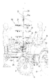
【図1】乗用田植機の要部側面図である。
【図2】同上要部正面図である。
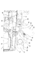
【図3】同上要部平面図である。
【図4】補助苗載台の位置決め構造を示す要部側面図である。
【図5】同上要部平面図である。
【図6】(A)は通常位置を示す補助苗載台の平面図、(B)は補給苗取出し用回動位置を示す補助苗載台の平面図、(C)は肥料供給用回動位置を示す補助苗載台の平面図である。
【符号の説明】
1 走行機体
2 機体フレーム
3 フロントアクスルケース
9 運転席
17 肥料タンク
17a 肥料供給口
18 補助苗載台装置
19 補助苗載台支柱
20 補助苗載台支持フレーム
21 補助苗載台
22 第一フレーム部材
23 第二フレーム部材
24 第三フレーム部材
25 回動操作レバー
27 位置決めプレート
29 上部連結フレーム[0001]
BACKGROUND OF THE INVENTION
The present invention belongs to the technical field of transplanting machines such as riding rice transplanters.
[0002]
[Prior art]
In general, a transplanter such as a riding rice transplanter includes auxiliary seedling platforms on the left and right sides of the front part of the machine body. This type of auxiliary seedling stage is configured in multiple stages, and at the time of seedling replenishment, the supplementary seedlings placed on each stage are taken out from the driver's seat side and placed on the seedling stage at the rear of the machine body.
Recently, in order to improve the workability at the time of seedling replenishment, there has been proposed a rotating auxiliary seedling stage. In this case, when the supplementary seedling is taken out from the auxiliary seedling stage, the direction of the auxiliary seedling stage can be freely changed, so that there is an advantage that the supplementary seedling can be easily taken out.
[0003]
[Problems to be solved by the invention]
However, some of the transplanters include a fertilizer tank in the vicinity of the auxiliary seedling stage. In such a transplanter, when the auxiliary seedling stage is configured as described above, the fertilizer supply operation to the fertilizer tank is performed. May interfere. That is, when the auxiliary seedling stage is arranged so as to overlap the fertilizer supply port of the fertilizer tank in a plan view, there arises a problem that the auxiliary seedling stage becomes an obstacle at the time of supplying fertilizer to the fertilizer tank. Therefore, conventionally, the auxiliary seedling support column is erected at the rearwardly spaced position of the fertilizer tank, but in this case, there is a possibility of adversely affecting the balance of the aircraft and the boarding / alighting performance of the aircraft.
[0004]
[Means for Solving the Problems]
The present invention has been created in view of the above circumstances and has been created for the purpose of solving these problems. The invention of
The invention of
[0005]
DETAILED DESCRIPTION OF THE INVENTION
Next, one embodiment of the present invention will be described with reference to the drawings. In the drawings,
[0006]
The
[0007]
The
[0008]
The
[0009]
18 is an auxiliary seedling table device provided on both left and right side portions of the front part of the machine body, and the auxiliary
[0010]
The auxiliary
[0011]
As described above, the
Moreover, as is apparent from FIGS. 1, 3, and 6, the auxiliary seedling
[0012]
A
[0013]
On the other hand, a fan-
[0014]
FIG. 6A shows the rotational position of the auxiliary
[0015]
Further,
[0016]
In the configuration configured as described above, in a transplanter including a fertilizer application device for applying fertilizer in the
[0017]
Further, the auxiliary
[0018]
The distance L from the auxiliary
[Brief description of the drawings]
FIG. 1 is a side view of a main part of a riding rice transplanter.
FIG. 2 is a front view of the relevant part.
FIG. 3 is a plan view of the main part of the same.
FIG. 4 is a side view of the main part showing the positioning structure of the auxiliary seedling placing stand.
FIG. 5 is a plan view of the relevant part.
6A is a plan view of an auxiliary seedling table showing a normal position, FIG. 6B is a plan view of an auxiliary seedling table showing a rotation position for removing a supplementary seedling, and FIG. 6C is a rotation for supplying fertilizer; It is a top view of the auxiliary seedling mounting stand which shows a position.
[Explanation of symbols]
DESCRIPTION OF
Claims (2)
Priority Applications (1)
| Application Number | Priority Date | Filing Date | Title |
|---|---|---|---|
| JP2001101677A JP4036619B2 (en) | 2001-03-30 | 2001-03-30 | Transplanter |
Applications Claiming Priority (1)
| Application Number | Priority Date | Filing Date | Title |
|---|---|---|---|
| JP2001101677A JP4036619B2 (en) | 2001-03-30 | 2001-03-30 | Transplanter |
Publications (2)
| Publication Number | Publication Date |
|---|---|
| JP2002291311A JP2002291311A (en) | 2002-10-08 |
| JP4036619B2 true JP4036619B2 (en) | 2008-01-23 |
Family
ID=18954959
Family Applications (1)
| Application Number | Title | Priority Date | Filing Date |
|---|---|---|---|
| JP2001101677A Expired - Fee Related JP4036619B2 (en) | 2001-03-30 | 2001-03-30 | Transplanter |
Country Status (1)
| Country | Link |
|---|---|
| JP (1) | JP4036619B2 (en) |
Families Citing this family (4)
| Publication number | Priority date | Publication date | Assignee | Title |
|---|---|---|---|---|
| JP5290212B2 (en) * | 2010-01-08 | 2013-09-18 | 三菱農機株式会社 | Transplanter |
| JP6069903B2 (en) * | 2012-06-19 | 2017-02-01 | 井関農機株式会社 | Spare seedling stand |
| JP5974996B2 (en) * | 2013-08-27 | 2016-08-23 | 井関農機株式会社 | Seedling transplanter |
| JP6024853B1 (en) * | 2016-07-21 | 2016-11-16 | 井関農機株式会社 | Seedling transplanter |
Family Cites Families (5)
| Publication number | Priority date | Publication date | Assignee | Title |
|---|---|---|---|---|
| JPH0697894B2 (en) * | 1986-10-14 | 1994-12-07 | 三菱農機株式会社 | Auxiliary seedling stand in seedling planting machine |
| JPH0726894Y2 (en) * | 1987-01-20 | 1995-06-21 | 三菱農機株式会社 | Auxiliary seedling stand support device in seedling planting machine |
| JP2944370B2 (en) * | 1993-08-03 | 1999-09-06 | 株式会社クボタ | Riding rice transplanter |
| JPH07115816A (en) * | 1993-10-29 | 1995-05-09 | Kubota Corp | Preliminary rice seedling-carrying part structure of riding type rice transplanter |
| JP2536465B2 (en) * | 1995-09-13 | 1996-09-18 | 井関農機株式会社 | Riding type seedling planter |
-
2001
- 2001-03-30 JP JP2001101677A patent/JP4036619B2/en not_active Expired - Fee Related
Also Published As
| Publication number | Publication date |
|---|---|
| JP2002291311A (en) | 2002-10-08 |
Similar Documents
| Publication | Publication Date | Title |
|---|---|---|
| JP4417093B2 (en) | Transplanter | |
| JP4036619B2 (en) | Transplanter | |
| JP2006109773A (en) | Reserve seedling-carrying platform in transplanter | |
| JP4512527B2 (en) | Transplanter | |
| JP2007151557A (en) | Transplanter | |
| JP3620300B2 (en) | Seedling transplanter | |
| JP2017121218A (en) | Riding rice planting machine | |
| JP3737378B2 (en) | Transplanter | |
| JP2016077200A (en) | Riding type paddy field work machine | |
| JP4591437B2 (en) | Seedling planting machine | |
| JP2002095318A (en) | Rice transplanter | |
| JP4510228B2 (en) | Mounting structure of marker for turning planting of rice transplanter | |
| JP5568269B2 (en) | Ride type rice transplanter | |
| JPH0514727Y2 (en) | ||
| JP4017589B2 (en) | Preliminary seedling placement structure for riding rice transplanter | |
| JP4732828B2 (en) | Transplanter | |
| JP5678811B2 (en) | Seedling transplanter | |
| JP5228640B2 (en) | Passenger rice transplanter | |
| JP2508841B2 (en) | Riding type seedling planter | |
| JPH085907Y2 (en) | Passenger paddy work machine steps | |
| JP5497581B2 (en) | Transplanter | |
| JP2019150074A (en) | Sulky rice planting machine | |
| JP2007097502A (en) | Transplanter | |
| JP4457463B2 (en) | Seedling planting machine | |
| JP3519982B2 (en) | Balance weight device for riding rice transplanter |
Legal Events
| Date | Code | Title | Description |
|---|---|---|---|
| A621 | Written request for application examination |
Free format text: JAPANESE INTERMEDIATE CODE: A621 Effective date: 20060331 |
|
| A977 | Report on retrieval |
Free format text: JAPANESE INTERMEDIATE CODE: A971007 Effective date: 20070525 |
|
| A131 | Notification of reasons for refusal |
Free format text: JAPANESE INTERMEDIATE CODE: A131 Effective date: 20070531 |
|
| A521 | Written amendment |
Free format text: JAPANESE INTERMEDIATE CODE: A523 Effective date: 20070727 |
|
| TRDD | Decision of grant or rejection written | ||
| A01 | Written decision to grant a patent or to grant a registration (utility model) |
Free format text: JAPANESE INTERMEDIATE CODE: A01 Effective date: 20071018 |
|
| A61 | First payment of annual fees (during grant procedure) |
Free format text: JAPANESE INTERMEDIATE CODE: A61 Effective date: 20071030 |
|
| FPAY | Renewal fee payment (event date is renewal date of database) |
Free format text: PAYMENT UNTIL: 20101109 Year of fee payment: 3 |
|
| LAPS | Cancellation because of no payment of annual fees |