JP5973756B2 - Focus position changing device and confocal optical device using the same - Google Patents
Focus position changing device and confocal optical device using the same Download PDFInfo
- Publication number
- JP5973756B2 JP5973756B2 JP2012057103A JP2012057103A JP5973756B2 JP 5973756 B2 JP5973756 B2 JP 5973756B2 JP 2012057103 A JP2012057103 A JP 2012057103A JP 2012057103 A JP2012057103 A JP 2012057103A JP 5973756 B2 JP5973756 B2 JP 5973756B2
- Authority
- JP
- Japan
- Prior art keywords
- rotating plate
- optical path
- light source
- light
- path changing
- Prior art date
- Legal status (The legal status is an assumption and is not a legal conclusion. Google has not performed a legal analysis and makes no representation as to the accuracy of the status listed.)
- Active
Links
Images


Classifications
-
- G—PHYSICS
- G02—OPTICS
- G02B—OPTICAL ELEMENTS, SYSTEMS OR APPARATUS
- G02B21/00—Microscopes
- G02B21/24—Base structure
- G02B21/248—Base structure objective (or ocular) turrets
-
- G—PHYSICS
- G02—OPTICS
- G02B—OPTICAL ELEMENTS, SYSTEMS OR APPARATUS
- G02B7/00—Mountings, adjusting means, or light-tight connections, for optical elements
- G02B7/02—Mountings, adjusting means, or light-tight connections, for optical elements for lenses
- G02B7/14—Mountings, adjusting means, or light-tight connections, for optical elements for lenses adapted to interchange lenses
- G02B7/16—Rotatable turrets
-
- G—PHYSICS
- G02—OPTICS
- G02B—OPTICAL ELEMENTS, SYSTEMS OR APPARATUS
- G02B21/00—Microscopes
- G02B21/0004—Microscopes specially adapted for specific applications
- G02B21/002—Scanning microscopes
- G02B21/0024—Confocal scanning microscopes (CSOMs) or confocal "macroscopes"; Accessories which are not restricted to use with CSOMs, e.g. sample holders
Landscapes
- Physics & Mathematics (AREA)
- General Physics & Mathematics (AREA)
- Optics & Photonics (AREA)
- Chemical & Material Sciences (AREA)
- Analytical Chemistry (AREA)
- Microscoopes, Condenser (AREA)
- Length Measuring Devices By Optical Means (AREA)
- Lens Barrels (AREA)
Description
本発明は、共焦点光学系に用いられ対物レンズの焦点位置を光軸方向に変更する焦点位置変更装置およびこれを用いた共焦点光学装置に関する。 The present invention relates to a focal position changing device that is used in a confocal optical system and changes the focal position of an objective lens in the optical axis direction, and a confocal optical device using the same.
共焦点光学系を用いた光学装置である共焦点光学装置は、被計測体表面の立体形状を計測する計測装置として利用され、あるいは被計測体表面を観察する顕微鏡として利用される。これらの目的で用いられる場合、共焦点光学装置は、被計測体表面上の各点に焦点を合わせる必要がある。このため、対物レンズの焦点位置を変更するための焦点位置変更装置を備えることが多い。 A confocal optical device that is an optical device using a confocal optical system is used as a measuring device that measures the three-dimensional shape of the surface of the measurement object, or as a microscope that observes the surface of the measurement object. When used for these purposes, the confocal optical device needs to focus on each point on the surface of the object to be measured. For this reason, a focal position changing device for changing the focal position of the objective lens is often provided.
従来、この種の焦点位置変更装置として、特開平9−126739号公報(特許文献1)に開示されたものがある。 Conventionally, as this type of focal position changing device, there is one disclosed in Japanese Patent Laid-Open No. 9-126739 (Patent Document 1).
この特許文献1に開示された焦点位置変更装置は、共焦点光学系に設けられ、互いに厚さが異なるかまたは互いに屈折率が異なる複数の平行平板形の透明体と、この複数の透明体が配列された回転体と、を備える。この焦点位置変更装置は、回転体の回転にともない光軸と順次交差する透明体の厚さまたは屈折率に応じて、対物レンズの焦点位置を光軸方向(被計測体の高さ方向)に変更できるようになっている。このため、この種の回転体を用いた焦点位置変更装置によれば、対物レンズの焦点位置を固定し被計測体の載置台を動かす場合に比べ、非常に高速かつ精細に焦点位置を変更することができる。 The focal position changing device disclosed in Patent Document 1 is provided in a confocal optical system, and includes a plurality of parallel plate-shaped transparent bodies having different thicknesses or different refractive indexes, and the plurality of transparent bodies. An arranged rotating body. This focal position changing device adjusts the focal position of the objective lens in the optical axis direction (height direction of the measured object) in accordance with the thickness or refractive index of the transparent body that sequentially intersects the optical axis as the rotating body rotates. It can be changed. For this reason, according to the focal position changing apparatus using this type of rotating body, the focal position is changed at a very high speed and finely compared with the case where the focal position of the objective lens is fixed and the mounting table of the measured object is moved. be able to.
しかし、回転体を用いた焦点位置変更装置を用いると、回転体自体が光軸と交差する期間が生じてしまう。回転体自体が光軸と交差すると、回転体により光が反射される。この回転体からの反射光は、被計測体からの反射光をあつかう共焦点撮像系にとっては本来不要なものであって、低減されることが望ましい。 However, when a focus position changing device using a rotator is used, a period in which the rotator itself intersects the optical axis occurs. When the rotator itself intersects the optical axis, the light is reflected by the rotator. The reflected light from the rotating body is essentially unnecessary for the confocal imaging system that handles the reflected light from the object to be measured, and is desirably reduced.
一方、回転体の透明体設置面は、透明体の傾きによる対物レンズの焦点位置のずれを防ぐため、研磨を施されるなどして平面度が高く設定されることが好ましい。ところが、平面度が高いと反射率が非常に高くなってしまい、回転体からの反射光がより多く共焦点撮像系に入力されてしまう。 On the other hand, it is preferable that the transparent body installation surface of the rotator is set to have high flatness by polishing or the like in order to prevent a shift of the focal position of the objective lens due to the inclination of the transparent body. However, if the flatness is high, the reflectance becomes very high, and more reflected light from the rotating body is input to the confocal imaging system.
本発明は、上述した事情を考慮してなされたもので、回転体からの反射光を抑制することができる焦点位置変更装置およびこれを用いた共焦点光学装置を提供することを目的とする。 The present invention has been made in consideration of the above-described circumstances, and an object of the present invention is to provide a focal position changing device that can suppress reflected light from a rotating body and a confocal optical device using the same.
本発明の一実施形態に係る焦点位置変更装置は、上述した課題を解決するために、光源、対物レンズを有する共焦点光学装置の光路上に設けられ、対物レンズの焦点位置を光軸方向に変更する焦点位置変更装置であって、それぞれ平行平板形の透明体により構成されるとともに屈折率および厚さの少なくとも一方が互いに異なる複数の光路変更片と、複数の光路変更片が対物レンズの光軸と交差するよう回転方向に沿って配設されるとともに、光源側の面の所定の領域に反射防止層が形成された回転板と、回転板を回転駆動する駆動部と、を備え、回転板は、複数の光路変更片のそれぞれに対応する複数の光線通過部、を有し、複数の光路変更片のそれぞれは、回転板の光源と反対側の面内の複数の光線通過部に対応する位置に設けられ、回転板の反射防止層は、回転板の光源側の面内の領域であって、複数の光路変更片のそれぞれに対応する複数の光線通過部を除く領域のうち少なくとも光源の光が照射される領域に形成されたものである。 In order to solve the above-described problem, a focal position changing device according to an embodiment of the present invention is provided on the optical path of a confocal optical device having a light source and an objective lens, and the focal position of the objective lens is set in the optical axis direction. A focal position changing device to be changed, each of which is composed of a parallel plate-shaped transparent body and has at least one of a refractive index and a thickness different from each other, and a plurality of optical path changing pieces are light of the objective lens A rotating plate that is disposed along the rotation direction so as to intersect the axis, and that has an antireflection layer formed in a predetermined region on the surface on the light source side, and a drive unit that drives the rotation plate to rotate. The plate has a plurality of light beam passage portions corresponding to each of the plurality of light path change pieces, and each of the plurality of light path change pieces corresponds to a plurality of light ray passage portions in a surface opposite to the light source of the rotating plate. Provided at the position where The antireflection layer of the plate is a region in the plane on the light source side of the rotating plate, and is a region to which at least light from the light source is irradiated among a plurality of light passage portions corresponding to each of the plurality of optical path changing pieces. It is formed .
本発明に係る焦点位置変更装置およびこれを用いた共焦点光学装置によれば、回転体からの反射光を抑制することができる。 According to the focal position changing device and the confocal optical device using the same according to the present invention, it is possible to suppress the reflected light from the rotating body.
本発明に係る焦点位置変更装置およびこれを用いた共焦点光学装置の実施の形態について、添付図面を参照して説明する。 Embodiments of a focal position changing apparatus and a confocal optical apparatus using the same according to the present invention will be described with reference to the accompanying drawings.
本発明の一実施形態に係る焦点位置変更装置を備えた共焦点光学装置は、2次元配列型の共焦点開口アレイまたはニポウディスクを有する共焦点光学系を用いて、たとえば被計測体表面の立体形状を計測するための計測装置として利用され、あるいは表面形状観察をするための顕微鏡として利用されるものである。計測対象物としては、たとえばICパッケージのような大量生産部品の電極端子(たとえば大きさ数十ミクロン〜数百ミクロン)などが挙げられる。 A confocal optical device including a focal position changing device according to an embodiment of the present invention uses a confocal optical system having a two-dimensional array type confocal aperture array or nipou disc, for example, a three-dimensional shape of the surface of a measurement object. It is used as a measuring device for measuring the surface or as a microscope for observing the surface shape. Examples of the measurement object include electrode terminals (for example, several tens of microns to several hundreds of microns) of mass-produced parts such as IC packages.
(第1の実施形態)
図1は、本発明の第1実施形態に係る焦点位置変更装置を備えた共焦点光学装置の一例を示す概略的な全体構成図である。なお、以下の説明では、光軸方向をZ軸、光軸方向に垂直な方向をX軸およびY軸とする場合の例について示す。また、以下の説明では、焦点位置変更装置を備えた共焦点光学装置が被計測体表面の立体形状を計測するための計測装置として利用される場合の例について示す。
(First embodiment)
FIG. 1 is a schematic overall configuration diagram illustrating an example of a confocal optical device including a focal position changing device according to a first embodiment of the present invention. In the following description, an example in which the optical axis direction is the Z axis and the directions perpendicular to the optical axis direction are the X axis and the Y axis will be described. Moreover, in the following description, an example in which a confocal optical device including a focal position changing device is used as a measurement device for measuring the three-dimensional shape of the surface of the measurement object will be described.
共焦点光学装置10は、光源11aを有する照明光学系11、主面が光軸方向に垂直となるよう配置された開口板12、対物レンズ13、焦点位置変更部14、被計測体15を載置するための載物台16、被計測体15からの反射光を入射される光検出器17aを複数有する光検出器群17、載物台16をXYZ各方向に移動させるための載物台駆動部18、載物台16および載物台駆動部18を支持する支持基台19、および画像処理装置20を有する。載物台駆動部18は、載物台Z変位部21および載物台XY変位部22を有する。
The confocal optical device 10 includes an illumination
光源11aとしては、たとえばハロゲンランプやレーザなどを用いることができる。光源11aから出射された光は、照明レンズ23を介して面状の照明光束となる。この光は、偏光ビームスプリッタ24を介して開口板12を照明する。
For example, a halogen lamp or a laser can be used as the
開口板12は、それぞれ共焦点開口部として機能する複数の開口部25を有する。開口板12には複数の開口部25が形成されていればよく、開口板12としては開口部25が2次元に配列されて開口アレイが形成されたものを用いてもよいし、いわゆるニポウディスクを用いてもよい。ニポウディスクを用いる場合、ニポウディスクは図示しない駆動機構により回転駆動される。
The
各開口部25を通過した光は、焦点位置変更部14を介して対物レンズ13を照射し、対物レンズ13によって被計測体15に投光されつつ開口部25と共役なスポット(物体側集光点)に集光される。各物体側集光点は、Z軸方向の所定の位置の光軸方向に垂直な面(以下、物体側集光面という)上に位置する。なお、対物レンズ13は、たとえば複数のレンズおよび絞りにより構成されて両側テレセントリック光学系を構成されてもよい。
The light that has passed through each
載物台Z変位部21は、ステッピングモータやサーボモータ、あるいはピエゾモータなどの一般的な駆動装置により構成され、載物台16を光軸方向に変位させる。この変位の量、方向およびタイミングは、画像処理装置20によりZ軸ドライバ30を介して制御される。載物台Z変位部21は、たとえば測定開始前に載物台16を光軸方向に大まかに変位させる。
The stage Z displacement unit 21 is configured by a general driving device such as a stepping motor, a servo motor, or a piezo motor, and displaces the
図2は、焦点位置変更部14の一構成例を示す斜視図である。図2には、光路変更片31が被計測体側の面に設けられる場合の例について示した。
FIG. 2 is a perspective view illustrating a configuration example of the focal
対物レンズ13の光路中に透明体により構成された平行平板形の光路変更片31を配置すると、対物レンズ13の物体側集光面の位置がZ方向に移動する。この焦点移動幅は、光路変更片31の屈折率および厚さによって制御することができる。
When a parallel plate-shaped optical
このため、図2に示すように、回転板32に対して回転方向に沿って等間隔に互いに焦点移動幅が異なる光路変更片31を配設する。この回転板32をモータなどの駆動部33により所定の速度で連続回転させることにより、光路変更片31のそれぞれが対物レンズ13の光軸と交わるごとに離散的に(ステップ的に)対物レンズ13の物体側集光面の位置をZ方向(光軸方向)に移動させることができる。なお、回転板32に配設された光路変更片31の一部は、他の光路変更片31と同一の屈折率および厚さを有し同一の焦点移動幅を有するものであってもよい。
Therefore, as shown in FIG. 2, optical
回転板32の回転状態はタイミングセンサ34により検知される。タイミングセンサ34の出力は画像処理装置20に与えられる。画像処理装置20は、あらかじめ各光路変更片31と物体側集光点のZ軸座標とを関連付けた情報を保持している。画像処理装置20がタイミングセンサ34の出力にもとづいて各光路変更片31と光軸とが交わるタイミングで光検出器群17を露光させることを繰り返すことにより、離散的な複数の物体側集光点の位置のそれぞれで、容易かつ高速に撮像を行うことができる。
The rotation state of the
駆動部33は、画像処理装置20により制御可能に構成されてもよい。この場合、画像処理装置20は回転板32の回転速度を制御することができる。
The
なお、図2には、複数の光路変更片31のそれぞれに対応する複数の光線通過部35が回転板32に貫通口として設けられるとともに、光路変更片31が回転板32の光源側の面(以下、光源側面という)36には設けられず、回転板32の光源11aと反対側の面(以下、被計測体側面という)37に光路変更片31が設けられる場合の例について示した。このとき、この場合、開口部25を通過した光は、貫通口としての光線通過部35を通過してから、光路変更片31を透過して被計測体15に向かう。
In FIG. 2, a plurality of light
また、以下の説明では光線通過部35および光路変更片31の形状が円形である場合の例について示すが、これらの形状は楕円形、多角形等であってもよい。
Moreover, although the following description shows an example in which the shapes of the light
被計測体15による反射光のうち特に物体側集光点における反射光は、対物レンズ13により、物体側集光点と光学的共役関係にある点(以下、像側集光点という)に集光される。点光源としての開口部25と物体側集光点とは、1対1に対応する。本実施形態では、像側集光点が点光源としての開口部25に一致する場合の例について説明する。この場合、開口部25を通過した光は物体側集光点に集光されるとともに、この物体側集光点で反射されて開口部25に再度入射することになる。
Of the reflected light from the
開口部25に再度入射した光は、偏光ビームスプリッタ24により偏向されて結像光学系38に入射し、光検出器群17を構成する光検出器17aに入射する。ここで、結像光学系38は、開口部25の像を光検出器群17の光電変換面に結ぶように構成される。開口部25(像側集光点)とこの開口部25に対応する位置に配設された光検出器17aとは、偏光ビームスプリッタ24および結像光学系38により互いに共役関係となる。
The light that has entered the
光検出器群17は、いわゆる2次元イメージセンサであり、光検出器群17を構成する光検出器17aは、CCD(Charge Coupled Device)イメージセンサやCMOS(Complementary Metal Oxide Semiconductor)イメージセンサにより構成されて、照射された光の強度に応じた信号を画像処理装置20に出力する。また、光検出器群17は、画像処理装置20により光検出のタイミングを制御される。
The
画像処理装置20は、この光検出器群17から受けた信号を、画像(以下、共焦点画像という)を生成するための画像データ(以下、共焦点画像データという)として用いることができる。また、画像処理装置20は、たとえば共焦点画像データにもとづく共焦点画像を露光ごとに生成してもよい。なお、画像処理装置20は、露光ごとに光検出器群17の出力信号を得ることができれば、この出力信号にもとづいて立体形状計測を行うことが可能であり、共焦点画像は必ずしも生成せずともよい。
The
画像処理装置20は、CPUなどの演算処理部、演算処理部により読み書き可能な記憶部、入力部および表示部などを有する一般的なパーソナルコンピュータなどの情報処理装置によって構成することができる。画像処理装置20の演算処理部は、少なくとも立体形状計測に必要な演算処理および共焦点光学装置10の動作の全般的な制御を実行する。
The
載物台駆動部18の載物台XY変位部22は、載物台16を光軸方向に垂直な方向に変位させる。たとえば、載物台XY変位部22は、測定の合間に測定対象領域をXY面内で移動させるために用いられる。
The mounting table XY displacement unit 22 of the mounting
この載物台XY変位部22は、載物台16のX軸方向およびY軸方向の位置決めを行うX軸変位機構41およびY軸変位機構42を有する。X軸変位機構41およびY軸変位機構42は、たとえばサーボモータにより構成され、変位の量、方向およびタイミングは、画像処理装置20によりXY軸ドライバ45を介して制御される。
The mounting table XY displacement unit 22 includes an X-axis displacement mechanism 41 and a Y-
次に、焦点位置変更部14の構成について詳細に説明する。
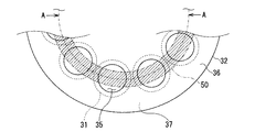
図3は、光路変更片31が被計測体側面37に設けられる場合における回転板32の一部の構成例を示す平面図である。
Next, the configuration of the focal
FIG. 3 is a plan view showing a configuration example of a part of the
回転板32の回転にともない、光源11aの光は光源側面36の帯状の領域(以下、光照射領域という)50を照射する。しかしながら、回転板32のうち被計測体15に向けて光を通過させるべき領域は光線通過部35のみである。たとえば回転板32が金属などの高反射率部材により構成され、光線通過部35が貫通口により構成される場合、光線通過部35における反射はおこらないものの、回転板32の光源側面36内の領域であって光線通過部35を除く領域のうち、光照射領域50に属する領域に照射された光は、光源側に反射されて光検出器群17に入射してしまう場合がある。
As the
ここで、回転板32の光路変更片31の設置面は、光路変更片31の傾きによる画像の横ずれを防ぐため、研磨を施されるなどして平面度が高く設定され、反射率が非常に高くなっている。このため、光路変更片31の設置面を光源側面36とすると、光検出器群17に入射される光源側面36の反射光が非常に多くなってしまう。
Here, the installation surface of the optical
そこで、本実施形態に係る焦点位置変更部14は、光路変更片31の設置面を被計測体側面37とし、光源側面36の反射光を抑制するよう構成される。
Therefore, the focal
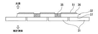
図4は、焦点位置変更部14の構成例の一部を図3のA−A線に沿って外周側から見た弧状の断面図である。
FIG. 4 is an arcuate cross-sectional view of a part of the configuration example of the focal
図4に示す焦点位置変更部14の構成例において、光線通過部35は貫通口により構成される。また、光路変更片31は、回転板32の被計測体側面37の、光線通過部35に対応する位置に設けられる。この場合、被計測体側面37はあらかじめ研磨を施されるなどして平面度が高く設定される。一方、光源側面36内の領域であって光線通過部35を除く領域のうち、少なくとも光照射領域50に属する領域には、反射防止層51が形成される。
In the configuration example of the focal
反射防止層51は、回転板32に貼り付けられた反射防止材、回転板32に塗布された黒色系塗料、回転板32の表面を粗面化して形成された層のいずれかまたはこれらの組み合わせにより形成することができる。
The
この第1構成例に係る焦点位置変更部14によれば、光源側面36に照射される光の反射を反射防止層51によって抑制することができる。
According to the focal
図5は、図4に示す焦点位置変更部14の構成例における回転板32の変形例を示す図である。
FIG. 5 is a view showing a modification of the
回転板32は、金属板などの高反射率部材により構成されてもよいし、透明体により構成されてもよい。透明体により構成される場合、光線通過部35にはなにも施されず、貫通口とされる必要はない。すなわち、透明体により構成される場合、回転板32は光線通過部35を含む全体を一枚の連続した板で構成することができる。
The rotating
回転板32を透明体により構成し、光線通過部35(図5の斜線部)にはなにも施さずに回転板32を貫通口のない一枚の連続した板とする場合、図4に示す構成例における回転板32をこの変形例に係る回転板32に置き換えればよい。図5には、図4に示す焦点位置変更部14の構成例における回転板32を変形例に係る回転板32に置き換える場合について例示した。
In the case where the
本実施形態に係る焦点位置変更部14および共焦点光学装置10によれば、光路変更片31の設置面に対して研磨を施すなどして平面度を高く設定することにより光路変更片31の意図しない傾きを防止しつつ、回転板32の光源側面36の反射光を抑制することができる。したがって、本実施形態に係る焦点位置変更部14を用いた共焦点光学装置10によれば、焦点位置を光軸方向に高速かつ精細に制御することができるとともに、光源側面36からの反射光の影響を低減した画像を取得することができる。
According to the focal
(第2の実施形態)
次に、本発明に係る焦点位置変更装置およびこれを用いた共焦点光学装置の第2実施形態について説明する。
(Second Embodiment)
Next, a second embodiment of the focal position changing device and the confocal optical device using the same according to the present invention will be described.
図6は、本発明の第2実施形態に係る共焦点光学装置10A(焦点位置変更部14を含む)の一例を示す概略的な全体構成図である。
FIG. 6 is a schematic overall configuration diagram illustrating an example of the confocal
この第2実施形態に示す共焦点光学装置10Aは、焦点位置変更部14が対物レンズ13の被計測体15側に設けられる点で第1実施形態に示す共焦点光学装置10と異なる。他の構成および作用については図1に示す共焦点光学装置10と実質的に異ならないため、同じ構成には同一符号を付して説明を省略する。
The confocal
図6に示すように、焦点位置変更部14は被計測体15側に設けられてもよい。この共焦点光学装置10Aによっても、第1実施形態に係る共焦点光学装置10と同様の作用効果を奏する。
As shown in FIG. 6, the focal
(第3の実施形態)
次に、本発明に係る焦点位置変更装置およびこれを用いた共焦点光学装置の第3実施形態について説明する。
(Third embodiment)
Next, a third embodiment of the focal position changing apparatus and the confocal optical apparatus using the same according to the present invention will be described.
図7は、本発明の第3実施形態に係る共焦点光学装置10B(焦点位置変更部14を含む)の一例を示す概略的な全体構成図である。 FIG. 7 is a schematic overall configuration diagram illustrating an example of the confocal optical device 10B (including the focal position changing unit 14) according to the third embodiment of the present invention.
この第3実施形態に示す共焦点光学装置10Bは、開口板12として開口部25が2次元に配列されて開口アレイが形成されたものを用い、この開口板12を開口板変位部60により光軸方向に垂直な所定の方向にリニアに変位させる点で第1実施形態に示す共焦点光学装置10と異なる。他の構成および作用については図1に示す共焦点光学装置10と実質的に異ならないため、同じ構成には同一符号を付して説明を省略する。
In the confocal optical device 10B shown in the third embodiment, an
一般に、2次元配列型の開口アレイの開口部25同士は、ビーム間のクロストークを小さくするために所定の離間距離をあけて設けられる必要がある。このため、2次元配列型の開口アレイを有する共焦点光学系では、この離間距離のために光軸に垂直な面内方向の分解能が制約されてしまう。一方、近年、固体撮像素子を用いた2次元イメージセンサは、非常に高画素のものが開発されてきている。
In general, the
そこで、本実施形態では、光検出器群17を露光させつつ、開口板変位部60により開口板12を光軸方向に垂直な所定の方向に直線的に走査することにより、1つの開口部25で複数の画素に対応させる。
Therefore, in the present embodiment, one
この共焦点光学装置10Bによっても、第1実施形態に係る共焦点光学装置10と同様の作用効果を奏する。また、本実施形態に係る共焦点光学装置10Bによれば、光軸に垂直な面内方向における取得される撮像画像の分解能を、より向上させることができる。 This confocal optical device 10B also has the same effects as the confocal optical device 10 according to the first embodiment. Further, according to the confocal optical device 10B according to the present embodiment, the resolution of the captured image acquired in the in-plane direction perpendicular to the optical axis can be further improved.
なお、本発明のいくつかの実施形態を説明したが、これらの実施形態は、例として提示したものであり、発明の範囲を限定することは意図していない。これら新規な実施形態は、その他の様々な形態で実施されることが可能であり、発明の要旨を逸脱しない範囲で、種々の省略、置き換え、変更を行うことができる。これら実施形態やその変形は、発明の範囲や要旨に含まれるとともに、特許請求の範囲に記載された発明とその均等の範囲に含まれる。 In addition, although some embodiment of this invention was described, these embodiment is shown as an example and is not intending limiting the range of invention. These novel embodiments can be implemented in various other forms, and various omissions, replacements, and changes can be made without departing from the scope of the invention. These embodiments and modifications thereof are included in the scope and gist of the invention, and are included in the invention described in the claims and the equivalents thereof.
10、10A、10B 共焦点光学装置
11 照明光学系
11a 光源
12 開口板
13 対物レンズ
14 焦点位置変更部
15 被計測体
17 光検出器群
17a 光検出器
25 開口部
31 光路変更片
32 回転板
33 駆動部
35 光線通過部
36 光源側面
37 被計測体側面
50 光照射領域
51 反射防止層
DESCRIPTION OF
Claims (4)
それぞれ平行平板形の透明体により構成されるとともに屈折率および厚さの少なくとも一方が互いに異なる複数の光路変更片と、
前記複数の光路変更片が前記対物レンズの光軸と交差するよう回転方向に沿って配設されるとともに、前記光源側の面の所定の領域に反射防止層が形成された回転板と、
前記回転板を回転駆動する駆動部と、
を備え、
前記回転板は、
前記複数の光路変更片のそれぞれに対応する複数の光線通過部、
を有し、
前記複数の光路変更片のそれぞれは、
前記回転板の前記光源と反対側の面内の前記複数の光線通過部に対応する位置に設けられ、
前記回転板の前記反射防止層は、
前記回転板の前記光源側の面内の領域であって、前記複数の光路変更片のそれぞれに対応する複数の光線通過部を除く領域のうち少なくとも前記光源の光が照射される領域に形成された、
焦点位置変更装置。 A focal position changing device provided on an optical path of a confocal optical device having a light source and an objective lens, and changing a focal position of the objective lens in an optical axis direction;
A plurality of optical path changing pieces each formed of a parallel plate-shaped transparent body and having at least one of a refractive index and a thickness different from each other;
A rotating plate in which the plurality of optical path changing pieces are disposed along the rotation direction so as to intersect the optical axis of the objective lens, and a reflection plate is formed in a predetermined region of the light source side surface;
A drive unit that rotationally drives the rotating plate;
Equipped with a,
The rotating plate is
A plurality of light beam passing portions corresponding to each of the plurality of optical path changing pieces,
Have
Each of the plurality of optical path changing pieces is
Provided at a position corresponding to the plurality of light beam passing portions in a surface opposite to the light source of the rotating plate;
The antireflection layer of the rotating plate is
It is an area in the surface on the light source side of the rotating plate, and is formed in at least an area irradiated with light from the light source among areas excluding a plurality of light beam passing portions corresponding to each of the plurality of optical path changing pieces. The
Focus position changing device.
前記複数の光路変更片が前記対物レンズの前記光源側の光軸と交差するよう、前記光源と前記対物レンズとの間の光路上に設けられた、
請求項1記載の焦点位置変更装置。 The rotating plate is
Provided on the optical path between the light source and the objective lens so that the plurality of optical path changing pieces intersects the optical axis of the objective lens on the light source side,
The focal position changing device according to claim 1.
前記回転板に貼り付けられた反射防止材、前記回転板に塗布された黒色系塗料、または前記回転板の表面を粗面化して形成された層のいずれかにより形成された、
請求項1または2に記載の焦点位置変更装置。 The antireflection layer is
The anti-reflective material attached to the rotating plate, the black paint applied to the rotating plate, or a layer formed by roughening the surface of the rotating plate,
The focal position changing device according to claim 1 or 2 .
複数の共焦点開口部が形成された開口板と、
前記複数の共焦点開口部を通過したそれぞれの光を物体側集光点に集光するとともに、この集光した光の被計測体による反射光をそれぞれ対応する共焦点開口部に再度集光する対物レンズと、
それぞれ平行平板形の透明体により構成されるとともに屈折率および厚さの少なくとも一方が互いに異なる複数の光路変更片と、前記複数の光路変更片が前記対物レンズの光軸と交差するよう回転方向に沿って配設されるとともに前記光源側の面の所定の領域に反射防止層が形成された回転板と、前記回転板を回転駆動する駆動部と、を有し、前記回転板の回転にともない光軸と交わる前記光路変更片が変わるごとに前記対物レンズの焦点を光軸方向に離散的に変更する焦点位置変更部と、
前記共焦点開口部に再度集光された前記被計測体による反射光を入力される撮像系と、
を備え、
前記回転板は、
前記複数の光路変更片のそれぞれに対応する複数の光線通過部、
を有し、
前記複数の光路変更片のそれぞれは、
前記回転板の前記光源と反対側の面内の前記複数の光線通過部に対応する位置に設けられ、
前記回転板の前記反射防止層は、
前記回転板の前記光源側の面内の領域であって、前記複数の光路変更片のそれぞれに対応する複数の光線通過部を除く領域のうち少なくとも前記光源の光が照射される領域に形成された、
共焦点光学装置。 A light source;
An aperture plate in which a plurality of confocal apertures are formed;
The respective lights that have passed through the plurality of confocal openings are condensed on the object-side condensing point, and the reflected light of the collected light from the measurement object is again condensed on the corresponding confocal openings. An objective lens;
A plurality of optical path changing pieces each formed of a parallel plate-shaped transparent body and having at least one of a refractive index and a thickness different from each other, and the plurality of optical path changing pieces in a rotation direction so as to intersect the optical axis of the objective lens And a rotation plate having an antireflection layer formed in a predetermined region on the light source side surface, and a drive unit that drives the rotation plate to rotate. As the rotation plate rotates A focal position changing unit that discretely changes the focal point of the objective lens in the optical axis direction each time the optical path changing piece intersecting the optical axis changes;
An imaging system that receives the reflected light from the object to be measured, which is condensed again at the confocal aperture;
Equipped with a,
The rotating plate is
A plurality of light beam passing portions corresponding to each of the plurality of optical path changing pieces,
Have
Each of the plurality of optical path changing pieces is
Provided at a position corresponding to the plurality of light beam passing portions in a surface opposite to the light source of the rotating plate;
The antireflection layer of the rotating plate is
It is an area in the surface on the light source side of the rotating plate, and is formed in at least an area irradiated with light from the light source among areas excluding a plurality of light beam passing portions corresponding to each of the plurality of optical path changing pieces. The
Confocal optical device.
Priority Applications (5)
| Application Number | Priority Date | Filing Date | Title |
|---|---|---|---|
| JP2012057103A JP5973756B2 (en) | 2012-03-14 | 2012-03-14 | Focus position changing device and confocal optical device using the same |
| US13/610,112 US9435982B2 (en) | 2012-03-14 | 2012-09-11 | Focus position changing apparatus and confocal optical apparatus using the same |
| TW101136680A TWI486555B (en) | 2012-03-14 | 2012-10-04 | Focus position changing apparatus and confocal optical apparatus using the same |
| KR1020120118659A KR101428864B1 (en) | 2012-03-14 | 2012-10-24 | Focus position changing apparatus and confocal optical apparatus using the same |
| CN201210488295.2A CN103309030B (en) | 2012-03-14 | 2012-11-26 | Focal position changes equipment and uses its confocal optics equipment |
Applications Claiming Priority (1)
| Application Number | Priority Date | Filing Date | Title |
|---|---|---|---|
| JP2012057103A JP5973756B2 (en) | 2012-03-14 | 2012-03-14 | Focus position changing device and confocal optical device using the same |
Publications (3)
| Publication Number | Publication Date |
|---|---|
| JP2013190624A JP2013190624A (en) | 2013-09-26 |
| JP2013190624A5 JP2013190624A5 (en) | 2015-02-12 |
| JP5973756B2 true JP5973756B2 (en) | 2016-08-23 |
Family
ID=49134432
Family Applications (1)
| Application Number | Title | Priority Date | Filing Date |
|---|---|---|---|
| JP2012057103A Active JP5973756B2 (en) | 2012-03-14 | 2012-03-14 | Focus position changing device and confocal optical device using the same |
Country Status (5)
| Country | Link |
|---|---|
| US (1) | US9435982B2 (en) |
| JP (1) | JP5973756B2 (en) |
| KR (1) | KR101428864B1 (en) |
| CN (1) | CN103309030B (en) |
| TW (1) | TWI486555B (en) |
Families Citing this family (6)
| Publication number | Priority date | Publication date | Assignee | Title |
|---|---|---|---|---|
| EP2511852B1 (en) * | 2011-04-15 | 2013-03-13 | Sick Ag | Lighting device for a camera-based code reader |
| CN105258686B (en) * | 2015-10-22 | 2019-02-01 | 青岛镭创光电技术有限公司 | Laser level |
| US10254105B2 (en) * | 2016-12-05 | 2019-04-09 | Quality Vision International, Inc. | Exchangeable lens module system for probes of optical measuring machines |
| JP6819362B2 (en) * | 2017-03-02 | 2021-01-27 | オムロン株式会社 | Confocal measuring device |
| JP2022552093A (en) * | 2019-10-19 | 2022-12-15 | アポロ メディカル オプティクス,エルティーディー. | Optical system and its interference objective module |
| CN115091107B (en) * | 2022-08-24 | 2023-04-25 | 中国工程物理研究院激光聚变研究中心 | High-precision clamping device and clamping method for laser processing |
Family Cites Families (20)
| Publication number | Priority date | Publication date | Assignee | Title |
|---|---|---|---|---|
| JPH095046A (en) * | 1995-06-21 | 1997-01-10 | Takaoka Electric Mfg Co Ltd | Three-dimensional shape measuring apparatus |
| US6426835B1 (en) * | 1999-03-23 | 2002-07-30 | Olympus Optical Co., Ltd. | Confocal microscope |
| JP2001083426A (en) | 1999-07-09 | 2001-03-30 | Olympus Optical Co Ltd | Confocal microscope |
| JP2001093426A (en) * | 1999-09-28 | 2001-04-06 | Matsushita Electric Ind Co Ltd | Ac type plasma display panel and drive method of the same |
| JP2001133695A (en) * | 1999-11-01 | 2001-05-18 | Nikon Corp | Microscope device |
| JP3714251B2 (en) * | 2000-03-27 | 2005-11-09 | トヨタ自動車株式会社 | Exhaust gas purification device |
| TW555954B (en) * | 2001-02-28 | 2003-10-01 | Olympus Optical Co | Confocal microscope, optical height-measurement method, automatic focusing method |
| JP4148350B2 (en) | 2002-05-24 | 2008-09-10 | 独立行政法人科学技術振興機構 | Confocal microscope and micro-aperture turntable |
| JP2005010516A (en) * | 2003-06-19 | 2005-01-13 | Olympus Corp | Microscope |
| US8238019B2 (en) * | 2003-11-01 | 2012-08-07 | Silicon Quest Kabushiki-Kaisha | Projection apparatus with coherent light source |
| US7704402B2 (en) * | 2004-10-27 | 2010-04-27 | Nikon Corporation | Optical element manufacturing method, optical element, Nipkow disk, confocal optical system and 3-D measurement device |
| JP2006235250A (en) * | 2005-02-25 | 2006-09-07 | Nikon Corp | Measuring microscope |
| TWI279580B (en) * | 2005-12-22 | 2007-04-21 | Metal Ind Res & Dev Ct | Co-focal microscopic imaging system with adjustable light source pattern |
| JP4867354B2 (en) | 2006-01-16 | 2012-02-01 | 横河電機株式会社 | Confocal microscope |
| JP4678601B2 (en) * | 2006-08-15 | 2011-04-27 | 横河電機株式会社 | Drug discovery screening device |
| JP2008096895A (en) * | 2006-10-16 | 2008-04-24 | Olympus Corp | Illuminator for microscope |
| WO2008069220A1 (en) * | 2006-11-30 | 2008-06-12 | Nikon Corporation | Imaging device and microscope |
| JP4970211B2 (en) * | 2007-10-18 | 2012-07-04 | ヘキサゴン・メトロジー株式会社 | 3D shape measuring instrument |
| US8042974B2 (en) * | 2007-10-23 | 2011-10-25 | American Dj Supply, Inc. | Removable, rotatable gobo holder assembly |
| JP2009168964A (en) | 2008-01-15 | 2009-07-30 | Nikon Corp | Confocal microscope |
-
2012
- 2012-03-14 JP JP2012057103A patent/JP5973756B2/en active Active
- 2012-09-11 US US13/610,112 patent/US9435982B2/en active Active
- 2012-10-04 TW TW101136680A patent/TWI486555B/en active
- 2012-10-24 KR KR1020120118659A patent/KR101428864B1/en not_active Application Discontinuation
- 2012-11-26 CN CN201210488295.2A patent/CN103309030B/en active Active
Also Published As
| Publication number | Publication date |
|---|---|
| TWI486555B (en) | 2015-06-01 |
| JP2013190624A (en) | 2013-09-26 |
| CN103309030B (en) | 2016-01-27 |
| TW201337215A (en) | 2013-09-16 |
| KR101428864B1 (en) | 2014-08-14 |
| US9435982B2 (en) | 2016-09-06 |
| KR20130105267A (en) | 2013-09-25 |
| US20130242396A1 (en) | 2013-09-19 |
| CN103309030A (en) | 2013-09-18 |
Similar Documents
| Publication | Publication Date | Title |
|---|---|---|
| KR101409644B1 (en) | Three-dimensional shape measuring apparatus | |
| JP5999121B2 (en) | Confocal light scanner | |
| JP5973756B2 (en) | Focus position changing device and confocal optical device using the same | |
| KR100474100B1 (en) | Confocal microscope and height measurement method using the same | |
| KR102362657B1 (en) | Wafer inspection | |
| US8610902B2 (en) | Apparatus and method for inspecting an object with increased depth of field | |
| JP5376076B1 (en) | Confocal scanner and optical measurement apparatus using the same | |
| JP5268061B2 (en) | Board inspection equipment | |
| RU2540453C2 (en) | Microscope, imaging device and imaging system | |
| JP2000275027A (en) | Slit confocal microscope and surface shape measuring apparatus using it | |
| JP6090607B2 (en) | Confocal scanner, confocal microscope | |
| JP6895768B2 (en) | Defect inspection equipment and defect inspection method | |
| JPWO2019159427A1 (en) | Camera module adjustment device and camera module adjustment method | |
| JP6226577B2 (en) | Confocal laser scanning microscope | |
| JP3509088B2 (en) | Optical device for three-dimensional shape measurement | |
| KR101867081B1 (en) | Confocal 3d sensing system with digital optical system | |
| JP2016148829A (en) | Observation device | |
| JP5822067B2 (en) | Microscope equipment | |
| JP2008261829A (en) | Surface measuring device | |
| JP2013011492A (en) | Three-dimentional image acquisition device and three-dimentional image acquisition method | |
| JP2008032995A (en) | Confocal microscope | |
| JP2012167930A (en) | Three-dimensional image acquisition device and three-dimensional image acquisition method |
Legal Events
| Date | Code | Title | Description |
|---|---|---|---|
| A711 | Notification of change in applicant |
Free format text: JAPANESE INTERMEDIATE CODE: A712 Effective date: 20140620 |
|
| A521 | Written amendment |
Free format text: JAPANESE INTERMEDIATE CODE: A523 Effective date: 20141217 |
|
| A621 | Written request for application examination |
Free format text: JAPANESE INTERMEDIATE CODE: A621 Effective date: 20141217 |
|
| A977 | Report on retrieval |
Free format text: JAPANESE INTERMEDIATE CODE: A971007 Effective date: 20151109 |
|
| A131 | Notification of reasons for refusal |
Free format text: JAPANESE INTERMEDIATE CODE: A131 Effective date: 20151201 |
|
| A521 | Written amendment |
Free format text: JAPANESE INTERMEDIATE CODE: A523 Effective date: 20160118 |
|
| TRDD | Decision of grant or rejection written | ||
| A01 | Written decision to grant a patent or to grant a registration (utility model) |
Free format text: JAPANESE INTERMEDIATE CODE: A01 Effective date: 20160705 |
|
| A61 | First payment of annual fees (during grant procedure) |
Free format text: JAPANESE INTERMEDIATE CODE: A61 Effective date: 20160715 |
|
| R150 | Certificate of patent or registration of utility model |
Ref document number: 5973756 Country of ref document: JP Free format text: JAPANESE INTERMEDIATE CODE: R150 |