JP5973109B1 - Light reflecting film, and light control film, optical film, functional glass and head-up display using the same - Google Patents
Light reflecting film, and light control film, optical film, functional glass and head-up display using the same Download PDFInfo
- Publication number
- JP5973109B1 JP5973109B1 JP2016513159A JP2016513159A JP5973109B1 JP 5973109 B1 JP5973109 B1 JP 5973109B1 JP 2016513159 A JP2016513159 A JP 2016513159A JP 2016513159 A JP2016513159 A JP 2016513159A JP 5973109 B1 JP5973109 B1 JP 5973109B1
- Authority
- JP
- Japan
- Prior art keywords
- light
- film
- prl
- light reflecting
- reflection
- Prior art date
- Legal status (The legal status is an assumption and is not a legal conclusion. Google has not performed a legal analysis and makes no representation as to the accuracy of the status listed.)
- Active
Links
- 239000010408 film Substances 0.000 title claims abstract description 228
- 239000011521 glass Substances 0.000 title claims abstract description 124
- 239000012788 optical film Substances 0.000 title claims abstract description 54
- 102100024601 Protein tyrosine phosphatase type IVA 3 Human genes 0.000 claims abstract description 47
- HXNBAOLVPAWYLT-NVNXTCNLSA-N (5z)-5-[[5-bromo-2-[(2-bromophenyl)methoxy]phenyl]methylidene]-2-sulfanylidene-1,3-thiazolidin-4-one Chemical compound S\1C(=S)NC(=O)C/1=C/C1=CC(Br)=CC=C1OCC1=CC=CC=C1Br HXNBAOLVPAWYLT-NVNXTCNLSA-N 0.000 claims abstract description 46
- 101710138647 Protein tyrosine phosphatase type IVA 3 Proteins 0.000 claims abstract description 46
- 102100024599 Protein tyrosine phosphatase type IVA 1 Human genes 0.000 claims abstract description 44
- 101710138644 Protein tyrosine phosphatase type IVA 1 Proteins 0.000 claims abstract description 44
- 102100024602 Protein tyrosine phosphatase type IVA 2 Human genes 0.000 claims abstract description 41
- 101710138646 Protein tyrosine phosphatase type IVA 2 Proteins 0.000 claims abstract description 40
- 239000005340 laminated glass Substances 0.000 claims description 33
- 238000002834 transmittance Methods 0.000 abstract description 43
- 230000010287 polarization Effects 0.000 abstract description 23
- 239000010410 layer Substances 0.000 description 254
- NIXOWILDQLNWCW-UHFFFAOYSA-M Acrylate Chemical compound [O-]C(=O)C=C NIXOWILDQLNWCW-UHFFFAOYSA-M 0.000 description 39
- 238000000034 method Methods 0.000 description 33
- 238000004519 manufacturing process Methods 0.000 description 32
- 239000004973 liquid crystal related substance Substances 0.000 description 22
- 239000004986 Cholesteric liquid crystals (ChLC) Substances 0.000 description 21
- -1 chalconyl group Chemical group 0.000 description 20
- 239000004988 Nematic liquid crystal Substances 0.000 description 17
- 238000010030 laminating Methods 0.000 description 17
- 239000000178 monomer Substances 0.000 description 16
- UWCWUCKPEYNDNV-LBPRGKRZSA-N 2,6-dimethyl-n-[[(2s)-pyrrolidin-2-yl]methyl]aniline Chemical compound CC1=CC=CC(C)=C1NC[C@H]1NCCC1 UWCWUCKPEYNDNV-LBPRGKRZSA-N 0.000 description 15
- 229920002799 BoPET Polymers 0.000 description 15
- 230000008859 change Effects 0.000 description 15
- 239000011248 coating agent Substances 0.000 description 14
- 238000000576 coating method Methods 0.000 description 14
- 230000031700 light absorption Effects 0.000 description 14
- 239000007788 liquid Substances 0.000 description 14
- 230000000694 effects Effects 0.000 description 13
- 239000000853 adhesive Substances 0.000 description 11
- 150000001875 compounds Chemical class 0.000 description 11
- 239000000203 mixture Substances 0.000 description 11
- 229920002037 poly(vinyl butyral) polymer Polymers 0.000 description 11
- 238000002310 reflectometry Methods 0.000 description 11
- 239000007795 chemical reaction product Substances 0.000 description 10
- 239000011229 interlayer Substances 0.000 description 10
- 229920005989 resin Polymers 0.000 description 10
- 239000011347 resin Substances 0.000 description 10
- 230000001070 adhesive effect Effects 0.000 description 9
- CERQOIWHTDAKMF-UHFFFAOYSA-N Methacrylic acid Chemical compound CC(=C)C(O)=O CERQOIWHTDAKMF-UHFFFAOYSA-N 0.000 description 8
- 238000010521 absorption reaction Methods 0.000 description 8
- 239000003999 initiator Substances 0.000 description 8
- 230000003595 spectral effect Effects 0.000 description 8
- 239000004820 Pressure-sensitive adhesive Substances 0.000 description 7
- 230000000052 comparative effect Effects 0.000 description 7
- ISAOCJYIOMOJEB-UHFFFAOYSA-N benzoin Chemical compound C=1C=CC=CC=1C(O)C(=O)C1=CC=CC=C1 ISAOCJYIOMOJEB-UHFFFAOYSA-N 0.000 description 6
- 238000011156 evaluation Methods 0.000 description 6
- 238000010438 heat treatment Methods 0.000 description 6
- NIXOWILDQLNWCW-UHFFFAOYSA-N acrylic acid group Chemical group C(C=C)(=O)O NIXOWILDQLNWCW-UHFFFAOYSA-N 0.000 description 5
- 239000012790 adhesive layer Substances 0.000 description 5
- 210000002858 crystal cell Anatomy 0.000 description 5
- 238000010586 diagram Methods 0.000 description 5
- TXBCBTDQIULDIA-UHFFFAOYSA-N 2-[[3-hydroxy-2,2-bis(hydroxymethyl)propoxy]methyl]-2-(hydroxymethyl)propane-1,3-diol Chemical compound OCC(CO)(CO)COCC(CO)(CO)CO TXBCBTDQIULDIA-UHFFFAOYSA-N 0.000 description 4
- 238000006243 chemical reaction Methods 0.000 description 4
- 230000003287 optical effect Effects 0.000 description 4
- 239000000243 solution Substances 0.000 description 4
- 239000002904 solvent Substances 0.000 description 4
- 239000000758 substrate Substances 0.000 description 4
- PEDCQBHIVMGVHV-UHFFFAOYSA-N Glycerine Chemical compound OCC(O)CO PEDCQBHIVMGVHV-UHFFFAOYSA-N 0.000 description 3
- 235000000126 Styrax benzoin Nutrition 0.000 description 3
- 244000028419 Styrax benzoin Species 0.000 description 3
- 235000008411 Sumatra benzointree Nutrition 0.000 description 3
- 239000007983 Tris buffer Substances 0.000 description 3
- 239000012752 auxiliary agent Substances 0.000 description 3
- 229960002130 benzoin Drugs 0.000 description 3
- 230000033228 biological regulation Effects 0.000 description 3
- 238000001816 cooling Methods 0.000 description 3
- 125000003700 epoxy group Chemical group 0.000 description 3
- 239000010419 fine particle Substances 0.000 description 3
- 235000019382 gum benzoic Nutrition 0.000 description 3
- ZFSLODLOARCGLH-UHFFFAOYSA-N isocyanuric acid Chemical compound OC1=NC(O)=NC(O)=N1 ZFSLODLOARCGLH-UHFFFAOYSA-N 0.000 description 3
- 229940059574 pentaerithrityl Drugs 0.000 description 3
- WXZMFSXDPGVJKK-UHFFFAOYSA-N pentaerythritol Chemical compound OCC(CO)(CO)CO WXZMFSXDPGVJKK-UHFFFAOYSA-N 0.000 description 3
- 229920000642 polymer Polymers 0.000 description 3
- 239000011342 resin composition Substances 0.000 description 3
- MLKIVXXYTZKNMI-UHFFFAOYSA-N 1-(4-dodecylphenyl)-2-hydroxy-2-methylpropan-1-one Chemical compound CCCCCCCCCCCCC1=CC=C(C(=O)C(C)(C)O)C=C1 MLKIVXXYTZKNMI-UHFFFAOYSA-N 0.000 description 2
- KWVGIHKZDCUPEU-UHFFFAOYSA-N 2,2-dimethoxy-2-phenylacetophenone Chemical compound C=1C=CC=CC=1C(OC)(OC)C(=O)C1=CC=CC=C1 KWVGIHKZDCUPEU-UHFFFAOYSA-N 0.000 description 2
- BTJPUDCSZVCXFQ-UHFFFAOYSA-N 2,4-diethylthioxanthen-9-one Chemical compound C1=CC=C2C(=O)C3=CC(CC)=CC(CC)=C3SC2=C1 BTJPUDCSZVCXFQ-UHFFFAOYSA-N 0.000 description 2
- LWRBVKNFOYUCNP-UHFFFAOYSA-N 2-methyl-1-(4-methylsulfanylphenyl)-2-morpholin-4-ylpropan-1-one Chemical compound C1=CC(SC)=CC=C1C(=O)C(C)(C)N1CCOCC1 LWRBVKNFOYUCNP-UHFFFAOYSA-N 0.000 description 2
- VVBLNCFGVYUYGU-UHFFFAOYSA-N 4,4'-Bis(dimethylamino)benzophenone Chemical compound C1=CC(N(C)C)=CC=C1C(=O)C1=CC=C(N(C)C)C=C1 VVBLNCFGVYUYGU-UHFFFAOYSA-N 0.000 description 2
- RTZKZFJDLAIYFH-UHFFFAOYSA-N Diethyl ether Chemical compound CCOCC RTZKZFJDLAIYFH-UHFFFAOYSA-N 0.000 description 2
- LYCAIKOWRPUZTN-UHFFFAOYSA-N Ethylene glycol Chemical compound OCCO LYCAIKOWRPUZTN-UHFFFAOYSA-N 0.000 description 2
- OFBQJSOFQDEBGM-UHFFFAOYSA-N Pentane Chemical compound CCCCC OFBQJSOFQDEBGM-UHFFFAOYSA-N 0.000 description 2
- ATUOYWHBWRKTHZ-UHFFFAOYSA-N Propane Chemical compound CCC ATUOYWHBWRKTHZ-UHFFFAOYSA-N 0.000 description 2
- 239000003522 acrylic cement Substances 0.000 description 2
- 125000003647 acryloyl group Chemical group O=C([*])C([H])=C([H])[H] 0.000 description 2
- 229910052782 aluminium Inorganic materials 0.000 description 2
- 230000001276 controlling effect Effects 0.000 description 2
- BGTOWKSIORTVQH-UHFFFAOYSA-N cyclopentanone Chemical compound O=C1CCCC1 BGTOWKSIORTVQH-UHFFFAOYSA-N 0.000 description 2
- 230000007423 decrease Effects 0.000 description 2
- 239000006185 dispersion Substances 0.000 description 2
- 239000005038 ethylene vinyl acetate Substances 0.000 description 2
- 230000001747 exhibiting effect Effects 0.000 description 2
- 230000001678 irradiating effect Effects 0.000 description 2
- 238000003475 lamination Methods 0.000 description 2
- 239000000463 material Substances 0.000 description 2
- QSHDDOUJBYECFT-UHFFFAOYSA-N mercury Chemical compound [Hg] QSHDDOUJBYECFT-UHFFFAOYSA-N 0.000 description 2
- 229910052753 mercury Inorganic materials 0.000 description 2
- CRVGTESFCCXCTH-UHFFFAOYSA-N methyl diethanolamine Chemical compound OCCN(C)CCO CRVGTESFCCXCTH-UHFFFAOYSA-N 0.000 description 2
- 238000002156 mixing Methods 0.000 description 2
- 230000035699 permeability Effects 0.000 description 2
- 229920003023 plastic Polymers 0.000 description 2
- 239000004033 plastic Substances 0.000 description 2
- 229920001200 poly(ethylene-vinyl acetate) Polymers 0.000 description 2
- 239000004417 polycarbonate Substances 0.000 description 2
- 229920000515 polycarbonate Polymers 0.000 description 2
- 229920001451 polypropylene glycol Polymers 0.000 description 2
- 238000002360 preparation method Methods 0.000 description 2
- 238000003825 pressing Methods 0.000 description 2
- 238000001228 spectrum Methods 0.000 description 2
- 230000001629 suppression Effects 0.000 description 2
- 229920001187 thermosetting polymer Polymers 0.000 description 2
- YRHRIQCWCFGUEQ-UHFFFAOYSA-N thioxanthen-9-one Chemical compound C1=CC=C2C(=O)C3=CC=CC=C3SC2=C1 YRHRIQCWCFGUEQ-UHFFFAOYSA-N 0.000 description 2
- XOLBLPGZBRYERU-UHFFFAOYSA-N tin dioxide Chemical compound O=[Sn]=O XOLBLPGZBRYERU-UHFFFAOYSA-N 0.000 description 2
- 229910001887 tin oxide Inorganic materials 0.000 description 2
- QNODIIQQMGDSEF-UHFFFAOYSA-N (1-hydroxycyclohexyl)-phenylmethanone Chemical compound C=1C=CC=CC=1C(=O)C1(O)CCCCC1 QNODIIQQMGDSEF-UHFFFAOYSA-N 0.000 description 1
- HJIAMFHSAAEUKR-UHFFFAOYSA-N (2-hydroxyphenyl)-phenylmethanone Chemical compound OC1=CC=CC=C1C(=O)C1=CC=CC=C1 HJIAMFHSAAEUKR-UHFFFAOYSA-N 0.000 description 1
- MSAHTMIQULFMRG-UHFFFAOYSA-N 1,2-diphenyl-2-propan-2-yloxyethanone Chemical compound C=1C=CC=CC=1C(OC(C)C)C(=O)C1=CC=CC=C1 MSAHTMIQULFMRG-UHFFFAOYSA-N 0.000 description 1
- YJTKZCDBKVTVBY-UHFFFAOYSA-N 1,3-Diphenylbenzene Chemical group C1=CC=CC=C1C1=CC=CC(C=2C=CC=CC=2)=C1 YJTKZCDBKVTVBY-UHFFFAOYSA-N 0.000 description 1
- DKEGCUDAFWNSSO-UHFFFAOYSA-N 1,8-dibromooctane Chemical compound BrCCCCCCCCBr DKEGCUDAFWNSSO-UHFFFAOYSA-N 0.000 description 1
- 239000012956 1-hydroxycyclohexylphenyl-ketone Substances 0.000 description 1
- CSCSROFYRUZJJH-UHFFFAOYSA-N 1-methoxyethane-1,2-diol Chemical compound COC(O)CO CSCSROFYRUZJJH-UHFFFAOYSA-N 0.000 description 1
- XLPJNCYCZORXHG-UHFFFAOYSA-N 1-morpholin-4-ylprop-2-en-1-one Chemical compound C=CC(=O)N1CCOCC1 XLPJNCYCZORXHG-UHFFFAOYSA-N 0.000 description 1
- YIKSHDNOAYSSPX-UHFFFAOYSA-N 1-propan-2-ylthioxanthen-9-one Chemical compound S1C2=CC=CC=C2C(=O)C2=C1C=CC=C2C(C)C YIKSHDNOAYSSPX-UHFFFAOYSA-N 0.000 description 1
- BRKORVYTKKLNKX-UHFFFAOYSA-N 2,4-di(propan-2-yl)thioxanthen-9-one Chemical compound C1=CC=C2C(=O)C3=CC(C(C)C)=CC(C(C)C)=C3SC2=C1 BRKORVYTKKLNKX-UHFFFAOYSA-N 0.000 description 1
- UXCIJKOCUAQMKD-UHFFFAOYSA-N 2,4-dichlorothioxanthen-9-one Chemical compound C1=CC=C2C(=O)C3=CC(Cl)=CC(Cl)=C3SC2=C1 UXCIJKOCUAQMKD-UHFFFAOYSA-N 0.000 description 1
- LZHUBCULTHIFNO-UHFFFAOYSA-N 2,4-dihydroxy-1,5-bis[4-(2-hydroxyethoxy)phenyl]-2,4-dimethylpentan-3-one Chemical compound C=1C=C(OCCO)C=CC=1CC(C)(O)C(=O)C(O)(C)CC1=CC=C(OCCO)C=C1 LZHUBCULTHIFNO-UHFFFAOYSA-N 0.000 description 1
- YSUQLAYJZDEMOT-UHFFFAOYSA-N 2-(butoxymethyl)oxirane Chemical compound CCCCOCC1CO1 YSUQLAYJZDEMOT-UHFFFAOYSA-N 0.000 description 1
- SJIXRGNQPBQWMK-UHFFFAOYSA-N 2-(diethylamino)ethyl 2-methylprop-2-enoate Chemical compound CCN(CC)CCOC(=O)C(C)=C SJIXRGNQPBQWMK-UHFFFAOYSA-N 0.000 description 1
- GJKGAPPUXSSCFI-UHFFFAOYSA-N 2-Hydroxy-4'-(2-hydroxyethoxy)-2-methylpropiophenone Chemical compound CC(C)(O)C(=O)C1=CC=C(OCCO)C=C1 GJKGAPPUXSSCFI-UHFFFAOYSA-N 0.000 description 1
- SYEWHONLFGZGLK-UHFFFAOYSA-N 2-[1,3-bis(oxiran-2-ylmethoxy)propan-2-yloxymethyl]oxirane Chemical compound C1OC1COCC(OCC1OC1)COCC1CO1 SYEWHONLFGZGLK-UHFFFAOYSA-N 0.000 description 1
- HDPLHDGYGLENEI-UHFFFAOYSA-N 2-[1-(oxiran-2-ylmethoxy)propan-2-yloxymethyl]oxirane Chemical compound C1OC1COC(C)COCC1CO1 HDPLHDGYGLENEI-UHFFFAOYSA-N 0.000 description 1
- WMYINDVYGQKYMI-UHFFFAOYSA-N 2-[2,2-bis(hydroxymethyl)butoxymethyl]-2-ethylpropane-1,3-diol Chemical compound CCC(CO)(CO)COCC(CC)(CO)CO WMYINDVYGQKYMI-UHFFFAOYSA-N 0.000 description 1
- COBPKKZHLDDMTB-UHFFFAOYSA-N 2-[2-(2-butoxyethoxy)ethoxy]ethanol Chemical compound CCCCOCCOCCOCCO COBPKKZHLDDMTB-UHFFFAOYSA-N 0.000 description 1
- AOBIOSPNXBMOAT-UHFFFAOYSA-N 2-[2-(oxiran-2-ylmethoxy)ethoxymethyl]oxirane Chemical compound C1OC1COCCOCC1CO1 AOBIOSPNXBMOAT-UHFFFAOYSA-N 0.000 description 1
- SHJIJMBTDZCOFE-UHFFFAOYSA-N 2-[2-[2-(2-hydroxyethoxy)ethoxy]ethoxy]-1-methoxyethanol Chemical compound COC(O)COCCOCCOCCO SHJIJMBTDZCOFE-UHFFFAOYSA-N 0.000 description 1
- SEFYJVFBMNOLBK-UHFFFAOYSA-N 2-[2-[2-(oxiran-2-ylmethoxy)ethoxy]ethoxymethyl]oxirane Chemical compound C1OC1COCCOCCOCC1CO1 SEFYJVFBMNOLBK-UHFFFAOYSA-N 0.000 description 1
- WTYYGFLRBWMFRY-UHFFFAOYSA-N 2-[6-(oxiran-2-ylmethoxy)hexoxymethyl]oxirane Chemical compound C1OC1COCCCCCCOCC1CO1 WTYYGFLRBWMFRY-UHFFFAOYSA-N 0.000 description 1
- FGTYTUFKXYPTML-UHFFFAOYSA-N 2-benzoylbenzoic acid Chemical compound OC(=O)C1=CC=CC=C1C(=O)C1=CC=CC=C1 FGTYTUFKXYPTML-UHFFFAOYSA-N 0.000 description 1
- UHFFVFAKEGKNAQ-UHFFFAOYSA-N 2-benzyl-2-(dimethylamino)-1-(4-morpholin-4-ylphenyl)butan-1-one Chemical compound C=1C=C(N2CCOCC2)C=CC=1C(=O)C(CC)(N(C)C)CC1=CC=CC=C1 UHFFVFAKEGKNAQ-UHFFFAOYSA-N 0.000 description 1
- ZCDADJXRUCOCJE-UHFFFAOYSA-N 2-chlorothioxanthen-9-one Chemical compound C1=CC=C2C(=O)C3=CC(Cl)=CC=C3SC2=C1 ZCDADJXRUCOCJE-UHFFFAOYSA-N 0.000 description 1
- 125000001731 2-cyanoethyl group Chemical group [H]C([H])(*)C([H])([H])C#N 0.000 description 1
- KMNCBSZOIQAUFX-UHFFFAOYSA-N 2-ethoxy-1,2-diphenylethanone Chemical compound C=1C=CC=CC=1C(OCC)C(=O)C1=CC=CC=C1 KMNCBSZOIQAUFX-UHFFFAOYSA-N 0.000 description 1
- RBMWDBHKRZTOMB-UHFFFAOYSA-N 2-ethoxy-1-phenylethanone Chemical compound CCOCC(=O)C1=CC=CC=C1 RBMWDBHKRZTOMB-UHFFFAOYSA-N 0.000 description 1
- QPXVRLXJHPTCPW-UHFFFAOYSA-N 2-hydroxy-2-methyl-1-(4-propan-2-ylphenyl)propan-1-one Chemical compound CC(C)C1=CC=C(C(=O)C(C)(C)O)C=C1 QPXVRLXJHPTCPW-UHFFFAOYSA-N 0.000 description 1
- XMLYCEVDHLAQEL-UHFFFAOYSA-N 2-hydroxy-2-methyl-1-phenylpropan-1-one Chemical compound CC(C)(O)C(=O)C1=CC=CC=C1 XMLYCEVDHLAQEL-UHFFFAOYSA-N 0.000 description 1
- 125000000954 2-hydroxyethyl group Chemical group [H]C([*])([H])C([H])([H])O[H] 0.000 description 1
- BQZJOQXSCSZQPS-UHFFFAOYSA-N 2-methoxy-1,2-diphenylethanone Chemical compound C=1C=CC=CC=1C(OC)C(=O)C1=CC=CC=C1 BQZJOQXSCSZQPS-UHFFFAOYSA-N 0.000 description 1
- MYISVPVWAQRUTL-UHFFFAOYSA-N 2-methylthioxanthen-9-one Chemical compound C1=CC=C2C(=O)C3=CC(C)=CC=C3SC2=C1 MYISVPVWAQRUTL-UHFFFAOYSA-N 0.000 description 1
- PYKUKGUIFBFVDR-UHFFFAOYSA-N 4,7-diazapentacyclo[10.7.1.02,11.03,8.016,20]icosa-1(19),2(11),3,5,7,9,12,14,16(20),17-decaene Chemical group C1=CC2=CC=CC(C=3C4=C5N=CC=NC5=CC=3)=C2C4=C1 PYKUKGUIFBFVDR-UHFFFAOYSA-N 0.000 description 1
- YDIYEOMDOWUDTJ-UHFFFAOYSA-N 4-(dimethylamino)benzoic acid Chemical compound CN(C)C1=CC=C(C(O)=O)C=C1 YDIYEOMDOWUDTJ-UHFFFAOYSA-N 0.000 description 1
- ZCYVEMRRCGMTRW-UHFFFAOYSA-N 7553-56-2 Chemical compound [I] ZCYVEMRRCGMTRW-UHFFFAOYSA-N 0.000 description 1
- 239000004925 Acrylic resin Substances 0.000 description 1
- 229920000178 Acrylic resin Polymers 0.000 description 1
- 229930185605 Bisphenol Natural products 0.000 description 1
- 229920000089 Cyclic olefin copolymer Polymers 0.000 description 1
- 239000004386 Erythritol Substances 0.000 description 1
- UNXHWFMMPAWVPI-UHFFFAOYSA-N Erythritol Natural products OCC(O)C(O)CO UNXHWFMMPAWVPI-UHFFFAOYSA-N 0.000 description 1
- 101000830691 Homo sapiens Protein tyrosine phosphatase type IVA 2 Proteins 0.000 description 1
- 101000830689 Homo sapiens Protein tyrosine phosphatase type IVA 3 Proteins 0.000 description 1
- 101000835900 Homo sapiens Submaxillary gland androgen-regulated protein 3B Proteins 0.000 description 1
- VQTUBCCKSQIDNK-UHFFFAOYSA-N Isobutene Chemical group CC(C)=C VQTUBCCKSQIDNK-UHFFFAOYSA-N 0.000 description 1
- 229920000877 Melamine resin Polymers 0.000 description 1
- BWPYBAJTDILQPY-UHFFFAOYSA-N Methoxyphenone Chemical compound C1=C(C)C(OC)=CC=C1C(=O)C1=CC=CC(C)=C1 BWPYBAJTDILQPY-UHFFFAOYSA-N 0.000 description 1
- NQSMEZJWJJVYOI-UHFFFAOYSA-N Methyl 2-benzoylbenzoate Chemical compound COC(=O)C1=CC=CC=C1C(=O)C1=CC=CC=C1 NQSMEZJWJJVYOI-UHFFFAOYSA-N 0.000 description 1
- OFSAUHSCHWRZKM-UHFFFAOYSA-N Padimate A Chemical compound CC(C)CCOC(=O)C1=CC=C(N(C)C)C=C1 OFSAUHSCHWRZKM-UHFFFAOYSA-N 0.000 description 1
- 238000006124 Pilkington process Methods 0.000 description 1
- 239000004698 Polyethylene Substances 0.000 description 1
- 239000002202 Polyethylene glycol Substances 0.000 description 1
- GSEJCLTVZPLZKY-UHFFFAOYSA-N Triethanolamine Chemical compound OCCN(CCO)CCO GSEJCLTVZPLZKY-UHFFFAOYSA-N 0.000 description 1
- SLINHMUFWFWBMU-UHFFFAOYSA-N Triisopropanolamine Chemical compound CC(O)CN(CC(C)O)CC(C)O SLINHMUFWFWBMU-UHFFFAOYSA-N 0.000 description 1
- ZJCCRDAZUWHFQH-UHFFFAOYSA-N Trimethylolpropane Chemical compound CCC(CO)(CO)CO ZJCCRDAZUWHFQH-UHFFFAOYSA-N 0.000 description 1
- DBHQYYNDKZDVTN-UHFFFAOYSA-N [4-(4-methylphenyl)sulfanylphenyl]-phenylmethanone Chemical compound C1=CC(C)=CC=C1SC1=CC=C(C(=O)C=2C=CC=CC=2)C=C1 DBHQYYNDKZDVTN-UHFFFAOYSA-N 0.000 description 1
- CSNCPNFITVRIBQ-UHFFFAOYSA-N [6-[4-[4-(4-prop-2-enoyloxybutoxycarbonyloxy)benzoyl]oxybenzoyl]oxy-2,3,3a,5,6,6a-hexahydrofuro[3,2-b]furan-3-yl] 4-[4-(4-prop-2-enoyloxybutoxycarbonyloxy)benzoyl]oxybenzoate Chemical compound C1=CC(OC(=O)OCCCCOC(=O)C=C)=CC=C1C(=O)OC1=CC=C(C(=O)OC2C3OCC(C3OC2)OC(=O)C=2C=CC(OC(=O)C=3C=CC(OC(=O)OCCCCOC(=O)C=C)=CC=3)=CC=2)C=C1 CSNCPNFITVRIBQ-UHFFFAOYSA-N 0.000 description 1
- VYGUBTIWNBFFMQ-UHFFFAOYSA-N [N+](#[C-])N1C(=O)NC=2NC(=O)NC2C1=O Chemical group [N+](#[C-])N1C(=O)NC=2NC(=O)NC2C1=O VYGUBTIWNBFFMQ-UHFFFAOYSA-N 0.000 description 1
- 239000003377 acid catalyst Substances 0.000 description 1
- XAGFODPZIPBFFR-UHFFFAOYSA-N aluminium Chemical compound [Al] XAGFODPZIPBFFR-UHFFFAOYSA-N 0.000 description 1
- 125000003277 amino group Chemical group 0.000 description 1
- 239000003963 antioxidant agent Substances 0.000 description 1
- 230000003078 antioxidant effect Effects 0.000 description 1
- 239000002216 antistatic agent Substances 0.000 description 1
- 238000000149 argon plasma sintering Methods 0.000 description 1
- 238000005452 bending Methods 0.000 description 1
- 239000012965 benzophenone Substances 0.000 description 1
- 150000008366 benzophenones Chemical class 0.000 description 1
- 230000005540 biological transmission Effects 0.000 description 1
- 125000006267 biphenyl group Chemical group 0.000 description 1
- MQDJYUACMFCOFT-UHFFFAOYSA-N bis[2-(1-hydroxycyclohexyl)phenyl]methanone Chemical compound C=1C=CC=C(C(=O)C=2C(=CC=CC=2)C2(O)CCCCC2)C=1C1(O)CCCCC1 MQDJYUACMFCOFT-UHFFFAOYSA-N 0.000 description 1
- IISBACLAFKSPIT-UHFFFAOYSA-N bisphenol A Chemical compound C=1C=C(O)C=CC=1C(C)(C)C1=CC=C(O)C=C1 IISBACLAFKSPIT-UHFFFAOYSA-N 0.000 description 1
- 239000004566 building material Substances 0.000 description 1
- HQABUPZFAYXKJW-UHFFFAOYSA-N butan-1-amine Chemical compound CCCCN HQABUPZFAYXKJW-UHFFFAOYSA-N 0.000 description 1
- CDQSJQSWAWPGKG-UHFFFAOYSA-N butane-1,1-diol Chemical compound CCCC(O)O CDQSJQSWAWPGKG-UHFFFAOYSA-N 0.000 description 1
- 125000003178 carboxy group Chemical group [H]OC(*)=O 0.000 description 1
- 239000003795 chemical substances by application Substances 0.000 description 1
- 239000003086 colorant Substances 0.000 description 1
- 238000004040 coloring Methods 0.000 description 1
- 239000002131 composite material Substances 0.000 description 1
- 239000004020 conductor Substances 0.000 description 1
- 229910052802 copper Inorganic materials 0.000 description 1
- 238000003851 corona treatment Methods 0.000 description 1
- 238000005520 cutting process Methods 0.000 description 1
- 230000003247 decreasing effect Effects 0.000 description 1
- 238000007872 degassing Methods 0.000 description 1
- XXJWXESWEXIICW-UHFFFAOYSA-N diethylene glycol monoethyl ether Chemical compound CCOCCOCCO XXJWXESWEXIICW-UHFFFAOYSA-N 0.000 description 1
- 238000009826 distribution Methods 0.000 description 1
- 238000001035 drying Methods 0.000 description 1
- 230000005684 electric field Effects 0.000 description 1
- 238000000295 emission spectrum Methods 0.000 description 1
- UNXHWFMMPAWVPI-ZXZARUISSA-N erythritol Chemical compound OC[C@H](O)[C@H](O)CO UNXHWFMMPAWVPI-ZXZARUISSA-N 0.000 description 1
- 229940009714 erythritol Drugs 0.000 description 1
- 235000019414 erythritol Nutrition 0.000 description 1
- 125000001033 ether group Chemical group 0.000 description 1
- 125000001495 ethyl group Chemical group [H]C([H])([H])C([H])([H])* 0.000 description 1
- 125000003055 glycidyl group Chemical group C(C1CO1)* 0.000 description 1
- 239000012760 heat stabilizer Substances 0.000 description 1
- RRAMGCGOFNQTLD-UHFFFAOYSA-N hexamethylene diisocyanate Chemical compound O=C=NCCCCCCN=C=O RRAMGCGOFNQTLD-UHFFFAOYSA-N 0.000 description 1
- 125000002887 hydroxy group Chemical group [H]O* 0.000 description 1
- WGCNASOHLSPBMP-UHFFFAOYSA-N hydroxyacetaldehyde Natural products OCC=O WGCNASOHLSPBMP-UHFFFAOYSA-N 0.000 description 1
- 230000006872 improvement Effects 0.000 description 1
- 229910052738 indium Inorganic materials 0.000 description 1
- 229910003437 indium oxide Inorganic materials 0.000 description 1
- PJXISJQVUVHSOJ-UHFFFAOYSA-N indium(iii) oxide Chemical compound [O-2].[O-2].[O-2].[In+3].[In+3] PJXISJQVUVHSOJ-UHFFFAOYSA-N 0.000 description 1
- 238000009413 insulation Methods 0.000 description 1
- 229910052740 iodine Inorganic materials 0.000 description 1
- 239000011630 iodine Substances 0.000 description 1
- 229910052742 iron Inorganic materials 0.000 description 1
- IQPQWNKOIGAROB-UHFFFAOYSA-N isocyanate group Chemical group [N-]=C=O IQPQWNKOIGAROB-UHFFFAOYSA-N 0.000 description 1
- HLJDOURGTRAFHE-UHFFFAOYSA-N isocyanic acid;3,5,5-trimethylcyclohex-2-en-1-one Chemical compound N=C=O.N=C=O.CC1=CC(=O)CC(C)(C)C1 HLJDOURGTRAFHE-UHFFFAOYSA-N 0.000 description 1
- 229910052748 manganese Inorganic materials 0.000 description 1
- JDSHMPZPIAZGSV-UHFFFAOYSA-N melamine Chemical compound NC1=NC(N)=NC(N)=N1 JDSHMPZPIAZGSV-UHFFFAOYSA-N 0.000 description 1
- 229910052751 metal Inorganic materials 0.000 description 1
- 239000002184 metal Substances 0.000 description 1
- 125000002816 methylsulfanyl group Chemical group [H]C([H])([H])S[*] 0.000 description 1
- 229910052750 molybdenum Inorganic materials 0.000 description 1
- UVEWQKMPXAHFST-UHFFFAOYSA-N n,1-diphenylmethanimine Chemical compound C=1C=CC=CC=1C=NC1=CC=CC=C1 UVEWQKMPXAHFST-UHFFFAOYSA-N 0.000 description 1
- 229910052759 nickel Inorganic materials 0.000 description 1
- 238000005121 nitriding Methods 0.000 description 1
- 239000002245 particle Substances 0.000 description 1
- FCJSHPDYVMKCHI-UHFFFAOYSA-N phenyl benzoate Chemical group C=1C=CC=CC=1C(=O)OC1=CC=CC=C1 FCJSHPDYVMKCHI-UHFFFAOYSA-N 0.000 description 1
- 125000001997 phenyl group Chemical group [H]C1=C([H])C([H])=C(*)C([H])=C1[H] 0.000 description 1
- LYXOWKPVTCPORE-UHFFFAOYSA-N phenyl-(4-phenylphenyl)methanone Chemical compound C=1C=C(C=2C=CC=CC=2)C=CC=1C(=O)C1=CC=CC=C1 LYXOWKPVTCPORE-UHFFFAOYSA-N 0.000 description 1
- IEQIEDJGQAUEQZ-UHFFFAOYSA-N phthalocyanine Chemical group N1C(N=C2C3=CC=CC=C3C(N=C3C4=CC=CC=C4C(=N4)N3)=N2)=C(C=CC=C2)C2=C1N=C1C2=CC=CC=C2C4=N1 IEQIEDJGQAUEQZ-UHFFFAOYSA-N 0.000 description 1
- 230000000704 physical effect Effects 0.000 description 1
- 239000000049 pigment Substances 0.000 description 1
- 238000009832 plasma treatment Methods 0.000 description 1
- 239000002985 plastic film Substances 0.000 description 1
- 229920006255 plastic film Polymers 0.000 description 1
- 229910052697 platinum Inorganic materials 0.000 description 1
- 229920000573 polyethylene Polymers 0.000 description 1
- 229920001223 polyethylene glycol Polymers 0.000 description 1
- 230000008569 process Effects 0.000 description 1
- 239000000047 product Substances 0.000 description 1
- 239000001294 propane Substances 0.000 description 1
- 230000001105 regulatory effect Effects 0.000 description 1
- 230000035945 sensitivity Effects 0.000 description 1
- 239000013464 silicone adhesive Substances 0.000 description 1
- 229910052709 silver Inorganic materials 0.000 description 1
- 239000005361 soda-lime glass Substances 0.000 description 1
- 239000000126 substance Substances 0.000 description 1
- 125000001424 substituent group Chemical group 0.000 description 1
- 238000004381 surface treatment Methods 0.000 description 1
- 229910052715 tantalum Inorganic materials 0.000 description 1
- 229910052718 tin Inorganic materials 0.000 description 1
- 229910052719 titanium Inorganic materials 0.000 description 1
- 239000005341 toughened glass Substances 0.000 description 1
- ZIBGPFATKBEMQZ-UHFFFAOYSA-N triethylene glycol Chemical compound OCCOCCOCCO ZIBGPFATKBEMQZ-UHFFFAOYSA-N 0.000 description 1
- JLGLQAWTXXGVEM-UHFFFAOYSA-N triethylene glycol monomethyl ether Chemical compound COCCOCCOCCO JLGLQAWTXXGVEM-UHFFFAOYSA-N 0.000 description 1
- 125000005580 triphenylene group Chemical group 0.000 description 1
- 229910052721 tungsten Inorganic materials 0.000 description 1
- 239000011882 ultra-fine particle Substances 0.000 description 1
- 239000006097 ultraviolet radiation absorber Substances 0.000 description 1
- 229910052720 vanadium Inorganic materials 0.000 description 1
- 125000000391 vinyl group Chemical group [H]C([*])=C([H])[H] 0.000 description 1
- 230000000007 visual effect Effects 0.000 description 1
- 239000013585 weight reducing agent Substances 0.000 description 1
- 229910052725 zinc Inorganic materials 0.000 description 1
Images


Classifications
-
- G—PHYSICS
- G02—OPTICS
- G02B—OPTICAL ELEMENTS, SYSTEMS OR APPARATUS
- G02B5/00—Optical elements other than lenses
- G02B5/08—Mirrors
- G02B5/0816—Multilayer mirrors, i.e. having two or more reflecting layers
-
- B—PERFORMING OPERATIONS; TRANSPORTING
- B60—VEHICLES IN GENERAL
- B60K—ARRANGEMENT OR MOUNTING OF PROPULSION UNITS OR OF TRANSMISSIONS IN VEHICLES; ARRANGEMENT OR MOUNTING OF PLURAL DIVERSE PRIME-MOVERS IN VEHICLES; AUXILIARY DRIVES FOR VEHICLES; INSTRUMENTATION OR DASHBOARDS FOR VEHICLES; ARRANGEMENTS IN CONNECTION WITH COOLING, AIR INTAKE, GAS EXHAUST OR FUEL SUPPLY OF PROPULSION UNITS IN VEHICLES
- B60K35/00—Arrangement of adaptations of instruments
-
- B60K35/22—
-
- B60K35/60—
-
- G—PHYSICS
- G02—OPTICS
- G02B—OPTICAL ELEMENTS, SYSTEMS OR APPARATUS
- G02B27/00—Optical systems or apparatus not provided for by any of the groups G02B1/00 - G02B26/00, G02B30/00
- G02B27/01—Head-up displays
-
- G—PHYSICS
- G02—OPTICS
- G02B—OPTICAL ELEMENTS, SYSTEMS OR APPARATUS
- G02B27/00—Optical systems or apparatus not provided for by any of the groups G02B1/00 - G02B26/00, G02B30/00
- G02B27/01—Head-up displays
- G02B27/0101—Head-up displays characterised by optical features
-
- G—PHYSICS
- G02—OPTICS
- G02B—OPTICAL ELEMENTS, SYSTEMS OR APPARATUS
- G02B5/00—Optical elements other than lenses
- G02B5/08—Mirrors
-
- G—PHYSICS
- G02—OPTICS
- G02B—OPTICAL ELEMENTS, SYSTEMS OR APPARATUS
- G02B5/00—Optical elements other than lenses
- G02B5/20—Filters
- G02B5/26—Reflecting filters
-
- G—PHYSICS
- G02—OPTICS
- G02B—OPTICAL ELEMENTS, SYSTEMS OR APPARATUS
- G02B5/00—Optical elements other than lenses
- G02B5/30—Polarising elements
-
- G—PHYSICS
- G02—OPTICS
- G02B—OPTICAL ELEMENTS, SYSTEMS OR APPARATUS
- G02B5/00—Optical elements other than lenses
- G02B5/30—Polarising elements
- G02B5/3083—Birefringent or phase retarding elements
-
- G—PHYSICS
- G02—OPTICS
- G02F—OPTICAL DEVICES OR ARRANGEMENTS FOR THE CONTROL OF LIGHT BY MODIFICATION OF THE OPTICAL PROPERTIES OF THE MEDIA OF THE ELEMENTS INVOLVED THEREIN; NON-LINEAR OPTICS; FREQUENCY-CHANGING OF LIGHT; OPTICAL LOGIC ELEMENTS; OPTICAL ANALOGUE/DIGITAL CONVERTERS
- G02F1/00—Devices or arrangements for the control of the intensity, colour, phase, polarisation or direction of light arriving from an independent light source, e.g. switching, gating or modulating; Non-linear optics
- G02F1/01—Devices or arrangements for the control of the intensity, colour, phase, polarisation or direction of light arriving from an independent light source, e.g. switching, gating or modulating; Non-linear optics for the control of the intensity, phase, polarisation or colour
- G02F1/13—Devices or arrangements for the control of the intensity, colour, phase, polarisation or direction of light arriving from an independent light source, e.g. switching, gating or modulating; Non-linear optics for the control of the intensity, phase, polarisation or colour based on liquid crystals, e.g. single liquid crystal display cells
- G02F1/133—Constructional arrangements; Operation of liquid crystal cells; Circuit arrangements
- G02F1/1333—Constructional arrangements; Manufacturing methods
- G02F1/1335—Structural association of cells with optical devices, e.g. polarisers or reflectors
-
- B60K2360/334—
-
- B60K2360/349—
-
- B60K2360/77—
-
- G—PHYSICS
- G02—OPTICS
- G02B—OPTICAL ELEMENTS, SYSTEMS OR APPARATUS
- G02B27/00—Optical systems or apparatus not provided for by any of the groups G02B1/00 - G02B26/00, G02B30/00
- G02B27/01—Head-up displays
- G02B27/0101—Head-up displays characterised by optical features
- G02B2027/0118—Head-up displays characterised by optical features comprising devices for improving the contrast of the display / brillance control visibility
- G02B2027/012—Head-up displays characterised by optical features comprising devices for improving the contrast of the display / brillance control visibility comprising devices for attenuating parasitic image effects
-
- G—PHYSICS
- G02—OPTICS
- G02B—OPTICAL ELEMENTS, SYSTEMS OR APPARATUS
- G02B27/00—Optical systems or apparatus not provided for by any of the groups G02B1/00 - G02B26/00, G02B30/00
- G02B27/01—Head-up displays
- G02B2027/0192—Supplementary details
- G02B2027/0194—Supplementary details with combiner of laminated type, for optical or mechanical aspects
Abstract
本発明は、高い可視光透過率を維持しながら、特定の偏光の反射率のみを有効に向上させることのできる光反射フィルム、ならびにこれを用いた光制御フィルム、光学フィルム、機能性ガラスおよびヘッドアップディスプレイを提案することにある。400nm以上500nm未満の中心反射波長をもち該中心反射波長での通常光に対する反射率が5%以上25%以下である光反射層PRL−1と、500nm以上600nm未満の中心反射波長をもち該中心反射波長での通常光に対する反射率が5%以上25%以下である光反射層PRL−2と、600nm以上700nm未満の中心反射波長をもち該中心反射波長での通常光に対する反射率が5%以上25%以下である光反射層PRL−3のうち、1つ以上の光反射層を含み、かつ互いに異なる中心反射波長をもつ少なくとも2つ以上の光反射層が積層され、積層される前記少なくとも2つ以上の光反射層は、いずれも同じ向きの偏光を反射する特性を有することを特徴とする光反射フィルム。The present invention relates to a light reflecting film capable of effectively improving only the reflectance of a specific polarization while maintaining a high visible light transmittance, and a light control film, an optical film, a functional glass and a head using the same. The idea is to propose an up-display. A light reflection layer PRL-1 having a central reflection wavelength of 400 nm or more and less than 500 nm and having a reflectance of 5% or more and 25% or less with respect to normal light at the central reflection wavelength, and a center reflection wavelength of 500 nm or more and less than 600 nm. The light reflection layer PRL-2 having a reflectance with respect to normal light at a reflection wavelength of 5% or more and 25% or less, and a center reflection wavelength of 600 nm or more and less than 700 nm, and a reflectance with respect to the ordinary light at the center reflection wavelength is 5%. The at least two or more light reflecting layers that include one or more light reflecting layers and have different central reflection wavelengths are laminated among the light reflecting layers PRL-3 that are 25% or less, The two or more light reflecting layers have a property of reflecting polarized light in the same direction.
Description
本発明は、例えばヘッドアップディスプレイに利用するのに好適な光反射フィルム、ならびにこれを用いた光制御フィルム、光学フィルム、機能性ガラスおよびヘッドアップディスプレイに関する。 The present invention relates to a light reflecting film suitable for use in, for example, a head-up display, and a light control film, an optical film, a functional glass and a head-up display using the same.
自動車や航空機等の運転者に情報を表示する方法として、ナビゲーションシステムやヘッドアップディスプレイ(以下、HUDともいう)等が用いられている。HUDは液晶表示体(以下、LCDという)等の画像投影手段から投射された画像を、例えば自動車のフロントガラス等に投影するシステムである。 As a method for displaying information to a driver of an automobile or an aircraft, a navigation system, a head-up display (hereinafter also referred to as HUD), or the like is used. The HUD is a system that projects an image projected from image projection means such as a liquid crystal display (hereinafter referred to as LCD) onto a windshield of an automobile, for example.
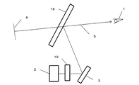
図1は、HUDの模式図である。画像表示手段2から出射した光は、光路5で示すように、反射鏡3にて反射し、フロントガラス4で反射した後、観察者1へ到達する。観察者1はフロントガラス4に投影された画像を見ているが、画像はフロントガラス4よりも遠方の画像位置6にあるように見える。この方法では、運転者はフロントガラス4の前方を注視した状態でほとんど視線を動かすことなく、様々な情報を入手することができるため、視線を移さなければならなかった従来のカーナビゲーションに比べ安全である。
FIG. 1 is a schematic diagram of a HUD. As shown by the
HUDは、表示情報を実際にフロントガラス4から見える景色に重ねて投影されるため、視界を遮ることなく、明るく見やすい画像を表示することが望ましい。そのためには、前景が十分に見えるだけの透過性と、HUDの反射画像が十分に見えるだけの反射性を兼ね備える必要がある。しかしながら、通常、透過率と反射率はトレードオフの関係にあり、一方を高くすれば他方は低くなるという問題があった。 Since the HUD is projected by superimposing display information on the scenery that is actually visible from the windshield 4, it is desirable to display a bright and easy-to-view image without obstructing the field of view. For that purpose, it is necessary to combine transparency that allows the foreground to be sufficiently seen, and reflectance that allows the reflected image of the HUD to be sufficiently seen. However, the transmittance and the reflectance are usually in a trade-off relationship, and there is a problem that if one is increased, the other is decreased.
特に、自動車用のフロントガラスの場合、ガラスに対する垂直方向の可視光透過率が70%以上という法的な制限があるために、高い反射率を有する部材の適用は難しい。このような課題に対し特許文献1〜4では、フロントガラスの合わせガラス内に偏光手段、偏光変調手段、反射性偏光手段を有するコンバイナーを設けることで、周囲の明るさに応じて偏光変調手段を制御し、コンバイナーの透過率や反射率を制御する技術が開示されている。
In particular, in the case of a windshield for automobiles, there is a legal limitation that the visible light transmittance in the vertical direction with respect to the glass is 70% or more, so it is difficult to apply a member having a high reflectance. In
また、特許文献5では光を反射する手段として、コレステリック液晶層を用い、自動車用のフロントガラス内に配置する技術が開示されている。
特許文献1、3および4の技術では、偏光変調手段として液晶セルを用いている。液晶セルは通常ガラス基板で作製されるために、曲面からなるフロントガラスの合わせガラス内へ適用することが困難である。また、近年、フロントガラス全面に画像を表示することが検討されており、合わせガラス全面に曲面状の液晶セルを用いて偏光変調することは極めて困難である。さらに、可視光透過率の法規制値を満たしつつも明るい画像をフロントガラスに表示し、かつ多彩なカラー表示に対応したHUDは未だ報告されていない。さらにまた、偏光手段および偏光変調手段である液晶セルには角度依存性があり、正面方向と傾けた方向では、偏光変調性能が異なるために、運転席からフロントガラス全面を均一な画質で見ることが困難であり、特にカラー表示の場合には運転手の見る場所によって表示色が変化してしまうという問題が生じてしまう。特許文献2、3、5においても、偏光性反射部材の角度依存性により、表示画像を斜めから見ると表示色が変化するだけでなく、これら偏光性反射部材を含むフロントガラスそのものが斜めから観察することで着色してしまい、自動車としてのデザインへ影響を及ぼすという問題がある。
In the techniques of
本発明の目的は、高い可視光透過率を維持しながら、特定の偏光の反射率のみを有効に向上させることのできる光反射フィルム、ならびにこれを用いた光制御フィルム、光学フィルム、機能性ガラスおよびヘッドアップディスプレイを提案することにある。 An object of the present invention is to provide a light reflecting film capable of effectively improving only the reflectance of a specific polarization while maintaining a high visible light transmittance, and a light control film, an optical film, and a functional glass using the same. And to propose a head-up display.
本発明者らは、上記課題を解決するため、鋭意検討した結果、400nm以上500nm未満の中心反射波長をもち該中心反射波長での通常光に対する反射率が5%以上25%以下である光反射層PRL−1と、500nm以上600nm未満の中心反射波長をもち該中心反射波長での通常光に対する反射率が5%以上25%以下である光反射層PRL−2と、600nm以上700nm未満の中心反射波長をもち該中心反射波長での通常光に対する反射率が5%以上25%以下である光反射層PRL−3のうち、1つ以上の光反射層を含み、互いに異なる中心反射波長をもつ少なくとも2つ以上の光反射層が積層され、積層される前記少なくとも2つ以上の光反射層は、いずれも同じ向きの偏光を反射する特性を有することを特徴とする光反射フィルムを用いることにより、フロントガラスの垂直方向の可視光透過率の規制値である70%以上を維持し、かつ、偏光を出射する投影機を用いて画像を投影することで、投影画像のみの反射率を通常光の反射率よりも大幅に向上させることができることを新規に見出し、本発明に至った。なお、PRLは、Polarized light Reflection Layerの略記であって、光反射層を意味するアルファベット表記である。 As a result of diligent studies to solve the above problems, the present inventors have a light reflection having a central reflection wavelength of 400 nm or more and less than 500 nm and having a reflectance of 5% or more and 25% or less with respect to normal light at the central reflection wavelength. Layer PRL-1, a light reflection layer PRL-2 having a central reflection wavelength of 500 nm or more and less than 600 nm and a reflectivity of 5% or more and 25% or less for normal light at the central reflection wavelength, and a center of 600 nm or more and less than 700 nm The light reflection layer PRL-3 having a reflection wavelength and having a reflectance with respect to normal light at the center reflection wavelength of 5% or more and 25% or less includes one or more light reflection layers and has different center reflection wavelengths. Light in which at least two or more light reflecting layers are laminated, and the laminated at least two or more light reflecting layers have characteristics of reflecting polarized light in the same direction. By using a projection film, the projected value is projected only by using a projector that emits polarized light while maintaining the vertical light transmittance limit value of 70% or more of the windshield in the vertical direction. The present inventors have newly found that the reflectance can be significantly improved from the reflectance of ordinary light, and the present invention has been achieved. PRL is an abbreviation for Polarized light Reflection Layer, and is an alphabetical notation meaning a light reflecting layer.
すなわち、本発明の要旨構成は、以下のとおりである。
(1)400nm以上500nm未満の中心反射波長をもち該中心反射波長での通常光に対する反射率が5%以上25%以下である光反射層PRL−1と、500nm以上600nm未満の中心反射波長をもち該中心反射波長での通常光に対する反射率が5%以上25%以下である光反射層PRL−2と、600nm以上700nm未満の中心反射波長をもち該中心反射波長での通常光に対する反射率が5%以上25%以下である光反射層PRL−3のうち、1つ以上の光反射層を含み、互いに異なる中心反射波長をもつ少なくとも2つ以上の光反射層が積層され、積層される前記少なくとも2つ以上の光反射層は、いずれも同じ向きの偏光を反射する特性を有することを特徴とする光反射フィルム。
(2)前記少なくとも2つ以上の光反射層は、前記光反射層PRL−1と、前記光反射層PRL−2と、前記光反射層PRL−3のうち、2つもしくは3つの光反射層を含むことを特徴とする、(1)に記載の光反射フィルム。
(3)前記少なくとも2つ以上の光反射層は、700nm以上950nm以下の中心反射波長をもち該中心反射波長での通常光に対する反射率が5%以上25%以下であって、かつ、(1)または(2)に記載された前記光反射層PRL−1、前記光反射層PRL−2および前記光反射層PRL−3と同じ向きの偏光を反射する特性を有する光反射層PRL−4を含むことを特徴とする、(1)または(2)に記載の光反射フィルム。
(4)各光反射層の半値幅が100nm以上、500nm以下であることを特徴とする、(1)ないし(3)のいずれか1つに記載の光反射フィルム。
(5)各光反射層が、固定化された螺旋配向を有するコレステリック液晶層であることを特徴とする、(1)ないし(4)のいずれか1つに記載の光反射フィルム。
(6)(1)ないし(5)のいずれか1項に記載の光反射フィルムと、1/4波長板および光吸収層の少なくとも一方の光制御層とが積層されていることを特徴とする光制御フィルム。
(7)前記光制御層が、1/4波長板であることを特徴とする(6)に記載の光制御フィルム。
(8)前記光制御層が、2枚の1/4波長板であり、前記光反射フィルムは、前記2枚の1/4波長板で挟持されるように積層されていることを特徴とする(7)に記載の光制御フィルム。
(9)前記2枚の1/4波長板は、遅相軸が互いに直交する位置関係で積層されていることを特徴とする、(8)に記載の光制御フィルム。
(10)(1)ないし(5)のいずれか1項に記載の光反射フィルムまたは(6)ないし(9)のいずれか1項に記載の光制御フィルムと、中間膜とを積層してなる光学フィルム。
(11)前記光反射フィルムまたは光制御フィルムが、2枚の中間膜で挟持されるように積層されていることを特徴とする、(10)に記載の光学フィルム。
(12)(1)ないし(5)のいずれか1項に記載の光反射フィルム、(6)ないし(9)のいずれか1項に記載の光制御フィルム、または(10)もしくは(11)に記載の光学フィルムのいずれかを有する機能性ガラス。
(13)(1)ないし(5)のいずれか1項に記載の光反射フィルム、(6)ないし(9)のいずれか1項に記載の光制御フィルム、または(10)もしくは(11)に記載の光学フィルムのいずれかを、2枚のガラス板によって挟持した合わせガラスにしたことを特徴とする、(12)に記載の機能性ガラス。
(14)(1)ないし(5)のいずれか1項に記載の光反射フィルム、(6)ないし(9)のいずれか1項に記載の光制御フィルム、または(10)もしくは(11)に記載の光学フィルム、または(12)もしくは(13)に記載の機能性ガラスのいずれかを用いたヘッドアップディスプレイ。
(15)画像表示するための投影機を有し、該投影機に、(1)ないし(5)のいずれか1項に記載の光反射フィルムの選択反射する円偏光と同じ向きの円偏光出射手段を設けたことを特徴とする、(14)に記載のヘッドアップディスプレイ。
(16)画像表示するための投影機を有し、該投影機に、P偏光を出射する手段を設けたことを特徴とする(14)に記載のヘッドアップディスプレイ。
(17)(6)ないし(9)のいずれか1項に記載の光制御フィルム、または、(10)もしくは(11)に記載の光学フィルムおよび(12)もしくは(13)に記載の機能性ガラスのうち、1/4波長板を積層した、光学フィルムおよび機能性ガラスのいずれかは、出射されたP偏光に対し、前記1/4波長板の遅相軸が45度になるように積層配置されていることを特徴とする(16)に記載のヘッドアップディスプレイ。That is, the gist configuration of the present invention is as follows.
(1) A light reflection layer PRL-1 having a central reflection wavelength of 400 nm or more and less than 500 nm and having a reflectance of 5% or more and 25% or less for normal light at the central reflection wavelength, and a central reflection wavelength of 500 nm or more and less than 600 nm A light reflection layer PRL-2 having a reflectance of 5% to 25% for normal light at the central reflection wavelength, and a reflectance for normal light at the central reflection wavelength of 600 nm to 700 nm. Among the light reflection layers PRL-3 having a thickness of 5% or more and 25% or less, at least two or more light reflection layers including one or more light reflection layers and having different central reflection wavelengths are laminated and laminated. The at least two or more light reflecting layers have a property of reflecting polarized light in the same direction.
(2) The at least two or more light reflection layers include two or three light reflection layers among the light reflection layer PRL-1, the light reflection layer PRL-2, and the light reflection layer PRL-3. The light reflecting film according to (1), comprising:
(3) The at least two or more light reflection layers have a central reflection wavelength of 700 nm or more and 950 nm or less, and reflectivity with respect to normal light at the central reflection wavelength is 5% or more and 25% or less, and (1 Or the light reflecting layer PRL-4 having the property of reflecting the polarized light in the same direction as the light reflecting layer PRL-1, the light reflecting layer PRL-2 and the light reflecting layer PRL-3 described in (2). The light reflecting film according to (1) or (2), wherein the light reflecting film is contained.
(4) The light reflecting film according to any one of (1) to (3), wherein the half width of each light reflecting layer is 100 nm or more and 500 nm or less.
(5) The light reflecting film according to any one of (1) to (4), wherein each light reflecting layer is a cholesteric liquid crystal layer having a fixed helical orientation.
(6) The light reflecting film according to any one of (1) to (5) and at least one light control layer of a quarter-wave plate and a light absorption layer are laminated. Light control film.
(7) The light control film according to (6), wherein the light control layer is a quarter-wave plate.
(8) The light control layer is two quarter-wave plates, and the light reflecting film is laminated so as to be sandwiched between the two quarter-wave plates. The light control film as described in (7).
(9) The light control film according to (8), wherein the two quarter-wave plates are laminated in a positional relationship in which slow axes are orthogonal to each other.
(10) The light reflecting film according to any one of (1) to (5) or the light control film according to any one of (6) to (9) and an intermediate film are laminated. Optical film.
(11) The optical film according to (10), wherein the light reflecting film or the light control film is laminated so as to be sandwiched between two intermediate films.
(12) The light reflecting film according to any one of (1) to (5), the light control film according to any one of (6) to (9), or (10) or (11) Functional glass having any of the optical films described.
(13) The light reflecting film according to any one of (1) to (5), the light control film according to any one of (6) to (9), or (10) or (11) The functional glass according to (12), wherein any one of the optical films described above is a laminated glass sandwiched between two glass plates.
(14) The light reflecting film according to any one of (1) to (5), the light control film according to any one of (6) to (9), or (10) or (11) A head-up display using any one of the optical film described in the above or the functional glass described in (12) or (13).
(15) A projector for displaying an image is provided, and the projector emits circularly polarized light in the same direction as the circularly polarized light selectively reflected by the light reflecting film according to any one of (1) to (5). The head-up display according to (14), characterized in that a means is provided.
(16) The head-up display according to (14), which has a projector for displaying an image and is provided with means for emitting P-polarized light.
(17) The light control film according to any one of (6) to (9), the optical film according to (10) or (11), and the functional glass according to (12) or (13) Among them, either the optical film or the functional glass on which the quarter wavelength plate is laminated is laminated so that the slow axis of the quarter wavelength plate is 45 degrees with respect to the emitted P-polarized light. The head-up display according to (16), wherein
本発明の光反射フィルムは、高い可視光透過率を有しながら、特定の偏光の反射率のみを有効に向上させることによって、HUDにおける投影画像の視認性を向上させることができ、特にフロントガラスのように可視光透過率が法的に規制されているような場合において、要求される可視光透過率を維持しながら、HUDにおける投影画像の視認性のみを向上させることができる。また、本発明の光反射フィルム、ならびにこれを用いた光制御フィルムおよび光学フィルムのいずれかを有する機能性ガラスは、フロントガラス全面のHUDにおける表示画像を明るく鮮明に映すことができ、運転者はフロントガラスのどの部分でも鮮明な画像を見ることができる。さらには、投影された画像を裸眼で見た場合でも、偏光サングラスをかけて見た場合でも明るい画像を見ることができる。 The light reflecting film of the present invention can improve the visibility of the projected image on the HUD by effectively improving only the reflectance of a specific polarization while having a high visible light transmittance. In such a case where the visible light transmittance is legally regulated, it is possible to improve only the visibility of the projected image on the HUD while maintaining the required visible light transmittance. Moreover, the functional glass having any of the light reflecting film of the present invention and the light control film and the optical film using the same can display a display image on the HUD of the entire windshield brightly and clearly. A clear image can be seen in any part of the windshield. Furthermore, a bright image can be seen even when the projected image is viewed with the naked eye or with polarized sunglasses.
本発明の光反射フィルムを構成する各光反射層は、特定の偏光に変換された画像表示手段から出射した光に対して高い反射率を有する特徴を持つ。偏光には、主に直線偏光と円偏光があるが、そのような偏光を反射する光反射層としては、例えば、直線偏光に対しては屈折率の異なる2種類以上の高分子からなる高分子多層膜からなる複屈折干渉型の偏光子や、ワイヤーグリッド型と呼ばれる微細な凹凸構造を有する偏光子が挙げられ、また、円偏光に対してはコレステリック液晶層からなる偏光子等が挙げられ、特に円偏光に対しては、コレステリック液晶層からなる偏光子が好ましい。 Each light reflecting layer constituting the light reflecting film of the present invention has a characteristic of having a high reflectance with respect to the light emitted from the image display means converted into the specific polarized light. Polarized light mainly includes linearly polarized light and circularly polarized light. As a light reflecting layer that reflects such polarized light, for example, a polymer composed of two or more kinds of polymers having different refractive indices with respect to linearly polarized light. Examples include a birefringence interference type polarizer made of a multilayer film and a polarizer having a fine uneven structure called a wire grid type, and for circularly polarized light, a polarizer made of a cholesteric liquid crystal layer, etc. In particular, for circularly polarized light, a polarizer composed of a cholesteric liquid crystal layer is preferable.
また、本発明の光反射フィルムは、画像表示手段から出射される光の波長に対して反射する必要があるため、可視光における青、緑、赤色の偏光に対して反射させる必要がある。一方で、自動車のフロントガラスのように法的に可視光透過率の規制があるような場合は、偏光フィルタ等によって特定の偏光成分だけを取りだす処理が施されていない光、いわゆる通常光に対する反射率が高すぎると透過率が低下し、使用できなくなってしまうため、通常光に対する光反射フィルムの反射率を適切に制御しなければならない。そのような光反射フィルムは、400nm以上500nm未満の中心反射波長をもち該中心反射波長での通常光に対する反射率が5%以上25%以下である光反射層PRL−1と、500nm以上600nm未満の中心反射波長をもち該中心反射波長での通常光に対する反射率が5%以上25%以下である光反射層PRL−2と、600nm以上700nm未満の中心反射波長をもち該中心反射波長での通常光に対する反射率が5%以上25%以下である光反射層PRL−3のうち1つ以上を含み、互いに異なる中心反射波長をもつ少なくとも2つ以上の光反射層が積層されている。このことは、本発明の光反射フィルムが、例えば、光反射層PRL−1、PRL−2、PRL−3のうちのいずれか1つの光反射層しか含んでいない場合には、光反射層PRL−1、PRL−2、PRL−3のいずれか1つのみの光反射層と、これらの光反射層とは異なる中心反射波長をもつ他の光反射層からなる群から選択される少なくとも1つ以上の光反射層との積層構造で構成されることを意味しており、光反射フィルムを構成する光反射層の層数は、少なくとも2つ以上であることが必要である。また、光反射層PRL−1、PRL−2、PRL−3のそれぞれの通常光に対する反射率は、好ましくは、10%以上25%以下、さらに好ましくは、15%以上20%以下程度とするのがよい。なお、各光反射層の中心反射波長での通常光に対する反射率は、上記の範囲内に調整できれば、いずれも同じあっても異なっていてもよい。 Moreover, since the light reflecting film of the present invention needs to reflect the wavelength of light emitted from the image display means, it is necessary to reflect blue, green and red polarized light in visible light. On the other hand, when the visible light transmittance is legally restricted, such as in the windshield of an automobile, the light that has not been processed to extract only a specific polarization component by a polarizing filter or the like, so-called reflection of normal light If the rate is too high, the transmittance is lowered and cannot be used. Therefore, the reflectance of the light reflecting film for normal light must be appropriately controlled. Such a light reflection film includes a light reflection layer PRL-1 having a central reflection wavelength of 400 nm or more and less than 500 nm and a reflectivity of 5% or more and 25% or less for normal light at the central reflection wavelength, and 500 nm or more and less than 600 nm. A light reflection layer PRL-2 having a central reflection wavelength of 5 to 25% with respect to normal light at the central reflection wavelength, and a central reflection wavelength of 600 nm to less than 700 nm. At least two or more light reflection layers having different central reflection wavelengths are stacked, including one or more of the light reflection layers PRL-3 having a reflectance of 5% to 25% for normal light. This is because, for example, when the light reflecting film of the present invention includes only one of the light reflecting layers PRL-1, PRL-2, and PRL-3, the light reflecting layer PRL. -1, PRL-2, or PRL-3, and at least one selected from the group consisting of another light reflecting layer having a central reflection wavelength different from those of the light reflecting layers. It means that it is configured by a laminated structure with the above light reflecting layers, and the number of light reflecting layers constituting the light reflecting film needs to be at least two. Further, the reflectance of each of the light reflection layers PRL-1, PRL-2, and PRL-3 with respect to normal light is preferably 10% or more and 25% or less, and more preferably 15% or more and 20% or less. Is good. In addition, as long as the reflectance with respect to the normal light in the center reflection wavelength of each light reflection layer can be adjusted in said range, all may be same or different.
本発明における中心反射波長とは、各光反射層の最大反射率の80%に相当する短波長側の波長と長波長側の波長の平均となる波長を意味する。例えば、PRL−1の最大反射率が20%であった場合、その80%に相当する16%の反射率を示す短波長側の波長をλ1、長波長側の波長をλ3とすると、下記式(1)で示されるλ2が中心反射波長となる。
(λ1+λ3)/2=λ2 (1)The central reflection wavelength in the present invention means a wavelength that is an average of the short wavelength side wavelength and the long wavelength side wavelength corresponding to 80% of the maximum reflectance of each light reflecting layer. For example, when the maximum reflectance of PRL-1 is 20%, assuming that the wavelength on the short wavelength side showing the reflectance of 16% corresponding to 80% is λ1, and the wavelength on the long wavelength side is λ3, the following formula Λ2 indicated by (1) is the central reflection wavelength.
(Λ1 + λ3) / 2 = λ2 (1)
また、本発明では、光反射層PRL−1、PRL−2、PRL−3のうち1つ以上を用いていれば、これらの光反射層は、各光反射層の反射帯域の広さに応じて積層数を調整することが可能である。HUDの画像表示手段からの光を所望とする分反射することが可能であれば、PRL−1、PRL−2、PRL−3のいずれか1層であってもよく、2層を積層してもよいし、3層共に積層してもよい。さらに、反射帯域を調整したい場合は、積層される光反射層には、光反射層PRL−1、PRL−2、PRL−3とは異なる中心反射波長をもつさらなる光反射層を用いることも可能であるが、後述する1/4波長板による円偏光から直線偏光への変換の際に、同じ向きの直線偏光に変換する必要性があるために、積層される各光反射層は、いずれも同じ向きの偏光を反射する特性を有することが必要である。 Further, in the present invention, if one or more of the light reflection layers PRL-1, PRL-2, and PRL-3 are used, these light reflection layers correspond to the width of the reflection band of each light reflection layer. The number of stacked layers can be adjusted. As long as the light from the HUD image display means can be reflected as much as desired, it may be one layer of PRL-1, PRL-2, or PRL-3. Alternatively, all three layers may be laminated. Furthermore, when the reflection band is to be adjusted, a further light reflection layer having a central reflection wavelength different from that of the light reflection layers PRL-1, PRL-2, and PRL-3 can be used as the laminated light reflection layer. However, in the case of conversion from circularly polarized light to linearly polarized light by the quarter wavelength plate described later, since it is necessary to convert to linearly polarized light in the same direction, each of the laminated light reflecting layers is It is necessary to have the property of reflecting polarized light in the same direction.
本発明での光反射フィルムは、光反射層がコレステリック液晶層である場合、入射してくる偏光が直線偏光であっても、円偏光であってもよいが、円偏光を入射させる方が好ましい。コレステリック液晶層は右回り円偏光もしくは左回り円偏光のいずれかを反射するように構成することができるが、円偏光には軸がないために、入射してくる偏光を光反射層が反射する右回り円偏光か左回り円偏光のいずれかを選択するだけで容易に、かつ、安定した高い反射率を得ることができる。 In the light reflecting film in the present invention, when the light reflecting layer is a cholesteric liquid crystal layer, the incident polarized light may be linearly polarized light or circularly polarized light, but it is preferable to make circularly polarized light incident. . The cholesteric liquid crystal layer can be configured to reflect either clockwise or counterclockwise circularly polarized light, but since circularly polarized light has no axis, the light reflecting layer reflects the incident polarized light. A stable high reflectance can be obtained easily by simply selecting either right-handed circularly polarized light or left-handed circularly polarized light.
円偏光を得る手段としては、例えば、染料系やヨウ素系といった吸収型の偏光板と1/4波長板とを、偏光板の吸収軸あるいは透過軸が、該1/4波長板の遅相軸あるいは進相軸に対して45度となるように配置すればよい。本発明においては、光反射層に到達するまでに円偏光となっていれば高い反射率を得ることができるため、偏光板と1/4波長板とを積層した、いわゆる円偏光板として、光反射層に入射させてもよいし、1/4波長板を光反射層とともに積層し、1/4波長板が偏光板側に位置するように配置してもよい。このような光反射フィルムと1/4波長板とを積層することによって、本発明の光制御フィルムを得ることができる。 As a means for obtaining circularly polarized light, for example, an absorption type polarizing plate such as a dye type or iodine type and a quarter wavelength plate are used, and the absorption axis or transmission axis of the polarizing plate is the slow axis of the quarter wavelength plate. Or what is necessary is just to arrange | position so that it may become 45 degree | times with respect to a fast axis. In the present invention, a high reflectance can be obtained if the circularly polarized light is reached before reaching the light reflecting layer. Therefore, as a so-called circularly polarizing plate in which a polarizing plate and a quarter wavelength plate are laminated, You may make it inject into a reflection layer, may laminate | stack a quarter wavelength plate with a light reflection layer, and may arrange | position so that a quarter wavelength plate may be located in the polarizing plate side. By laminating such a light reflecting film and a quarter wave plate, the light control film of the present invention can be obtained.
光反射層に用いられるコレステリック液晶とは、キラリティを持つネマチック液晶やネマチック液晶にカイラル剤を添加した配合物からなる。カイラル剤の種類や量により、螺旋の向きや反射波長を任意に設計できることから、ネマチック液晶にカイラル剤を添加してコレステリック液晶を得る方法が好ましい。本発明で使用されるネマチック液晶は、いわゆる電界で操作する液晶とは異なり、螺旋配向状態を固定化して使用されるため、重合性基を有するネマチック液晶モノマーを用いることが好ましい。 The cholesteric liquid crystal used for the light reflecting layer is composed of nematic liquid crystal having chirality or a composition in which a chiral agent is added to nematic liquid crystal. Since the direction of the spiral and the reflection wavelength can be arbitrarily designed depending on the kind and amount of the chiral agent, a method of obtaining a cholesteric liquid crystal by adding a chiral agent to a nematic liquid crystal is preferable. The nematic liquid crystal used in the present invention is different from the so-called liquid crystal operated by an electric field, and is used by fixing the helical alignment state. Therefore, it is preferable to use a nematic liquid crystal monomer having a polymerizable group.
重合性基を有するネマチック液晶モノマーとは、分子内に重合性基を有し、ある温度範囲あるいは濃度範囲で液晶性を示す化合物である。重合性基としては、例えば(メタ)アクリロイル基、ビニル基、カルコニル基、シンナモイル基、またはエポキシ基などが挙げられる。また、液晶性を示すためには分子内にメソゲン基があることが好ましく、メソゲン基とは、例えばビフェニル基、ターフェニル基、(ポリ)安息香酸フェニルエステル基、(ポリ)エーテル基、ベンジリデンアニリン基、またはアセナフトキノキサリン基等のロッド状、板状、あるいはトリフェニレン基、フタロシアニン基、またはアザクラウン基等の円盤状の置換基、即ち液晶相挙動を誘導する能力を有する基を意味する。ロッド状または板状基を有する液晶化合物はカラミティック液晶として当該技術分野で既知である。このような重合性基を有するネマチック液晶モノマーは具体的には特開2003−315556号公報および特開2004−29824号公報に記載の重合性液晶や、PALIOCOLORシリーズ(BASF社製)、RMMシリーズ(Merck社製)等が挙げられる。これら重合性基を有するネマチック液晶モノマーは単独でも、あるいは複数混合して用いることができる。 A nematic liquid crystal monomer having a polymerizable group is a compound having a polymerizable group in the molecule and exhibiting liquid crystallinity in a certain temperature range or concentration range. Examples of the polymerizable group include (meth) acryloyl group, vinyl group, chalconyl group, cinnamoyl group, and epoxy group. In order to exhibit liquid crystallinity, a mesogenic group is preferable in the molecule. Examples of the mesogenic group include a biphenyl group, a terphenyl group, a (poly) benzoic acid phenyl ester group, a (poly) ether group, and a benzylidene aniline. Or a rod-like, plate-like or acenaphthoquinoxaline group or a disc-like substituent such as a triphenylene group, a phthalocyanine group or an azacrown group, that is, a group having the ability to induce liquid crystal phase behavior. Liquid crystal compounds having rod-like or plate-like groups are known in the art as calamitic liquid crystals. Specifically, nematic liquid crystal monomers having such a polymerizable group include polymerizable liquid crystals described in JP-A Nos. 2003-315556 and 2004-29824, PALIOCOLOR series (manufactured by BASF), RMM series ( Merck)). These nematic liquid crystal monomers having a polymerizable group can be used alone or in combination.
カイラル剤としては、上記重合性基を有するネマチック液晶モノマーを右巻きあるいは左巻き螺旋配向させることができ、重合性基を有するネマチック液晶モノマーと同様に重合性基を有する化合物が好ましい。そのようなカイラル剤としては、例えば、Paliocolor LC756(BASF社製)、特開2002−179668号公報に記載されている化合物などが挙げられる。このカイラル剤の種類により、反射する円偏光の向きが決まり、さらには、ネマチック液晶に対するカイラル剤の添加量に応じて、光反射層の反射波長を変えることができる。例えば、カイラル剤の添加量を多くするほど、短波長側の波長を反射する光反射層を得ることができる。カイラル剤の添加量は、カイラル剤の種類と反射させる波長によっても異なるが、通常光に対する光反射層の中心反射波長λ2を、所望の波長領域に調整するため、重合性基を有するネマチック液晶モノマー100重量部に対し、0.5〜30重量部程度が好ましく、より好ましくは1〜20重量部程度であり、さらに好ましくは3〜10重量部程度である。 As the chiral agent, a nematic liquid crystal monomer having a polymerizable group can be right-handed or left-handed and spirally aligned, and a compound having a polymerizable group is preferred similarly to a nematic liquid crystal monomer having a polymerizable group. Examples of such chiral agents include compounds described in Paliocolor LC756 (manufactured by BASF) and JP-A No. 2002-179668. The direction of the circularly polarized light to be reflected is determined by the kind of the chiral agent, and the reflection wavelength of the light reflecting layer can be changed according to the amount of the chiral agent added to the nematic liquid crystal. For example, as the amount of the chiral agent added is increased, a light reflecting layer that reflects a wavelength on the short wavelength side can be obtained. The amount of the chiral agent added varies depending on the type of the chiral agent and the wavelength to be reflected, but in order to adjust the central reflection wavelength λ2 of the light reflection layer for normal light to a desired wavelength region, a nematic liquid crystal monomer having a polymerizable group The amount is preferably about 0.5 to 30 parts by weight, more preferably about 1 to 20 parts by weight, and still more preferably about 3 to 10 parts by weight with respect to 100 parts by weight.
さらに、重合性基を有するネマチック液晶モノマーと反応可能な液晶性を有しない重合性化合物を添加することも可能である。そのような化合物としては例えば紫外線硬化型樹脂等が挙げられる。紫外線硬化型樹脂としては、例えばジペンタエリスリトールヘキサ(メタ)アクリレート、ジペンタエリスリトールペンタ(メタ)アクリレートと1,6−ヘキサメチレン−ジ−イソシアネートとの反応生成物、イソシアヌル環を有するトリイソシアネートとペンタエリスリトールトリ(メタ)アクリレートとの反応生成物、ペンタエリスリトールトリ(メタ)アクリレートとイソホロン−ジ−イソシアネートとの反応生成物、ジペンタエリスリトールペンタ(メタ)アクリレート、ジペンタエリスリトールテトラ(メタ)アクリレート、ペンタエリスリトールテトラ(メタ)アクリレート、ペンタエリスリトールトリ(メタ)アクリレート、トリメチロールプロパントリ(メタ)アクリレート、ジトリメチロールプロパンテトラ(メタ)アクリレート、トリス(アクリロキシエチル)イソシアヌレート、トリス(メタアクリロキシエチル)イソシアヌレート、グリセロールトリグリシジルエーテルと(メタ)アクリル酸との反応生成物、カプロラクトン変性トリス(アクリロキシエチル)イソシアヌレート、トリメチロールプロパントリグリシジルエーテルと(メタ)アクリル酸との反応生成物、トリグリセロール−ジ−(メタ)アクリレート、プロピレングリコール−ジ−グリシジルエーテルと(メタ)アクリル酸との反応生成物、ポリプロピレングリコール−ジ−(メタ)アクリレート、トリプロピレングリコール−ジ−(メタ)アクリレート、ポリエチレングリコール−ジ−(メタ)アクリレート、テトラエチレングリコール−ジ−(メタ)アクリレート、トリエチレングリコール−ジ−(メタ)アクリレート、ペンタエリスリトール−ジ−(メタ)アクリレート、1,6−ヘキサンジオール−ジ−グリシジルエーテルと(メタ)アクリル酸との反応生成物、1,6−ヘキサンジオール−ジ−(メタ)アクリレート、グリセロール−ジ−(メタ)アクリレート、エチレングリコール−ジ−グリシジルエーテルと(メタ)アクリル酸との反応生成物、ジエチレングリコール−ジ−グリシジルエーテルと(メタ)アクリル酸との反応生成物、ビス(アクリロキシエチル)ヒドロキシエチルイソシアヌレート、ビス(メタアクリロキシエチル)ヒドロキシエチルイソシアヌレート、ビスフェノールA−ジ−グリシジルエーテルと(メタ)アクリル酸との反応生成物、テトラヒドロフルフリル(メタ)アクリレート、カプロラクトン変性テトラヒドロフルフリル(メタ)アクリレート、2−ヒドロキシエチル(メタ)アクリレート、2−ヒドロキシプロピル(メタ)アクリレート、ポリプロピレングリコール(メタ)アクリレート、ポリエチレングリコール(メタ)アクリレート、フェノキシヒドロキシプロピル(メタ)アクリレート、アクリロイルモルホリン、メトキシポリエチレングリコール(メタ)アクリレート、メトキシテトラエチレングリコール(メタ)アクリレート、メトキシトリエチレングリコール(メタ)アクリレート、メトキシエチレングリコール(メタ)アクリレート、メトキシエチル(メタ)アクリレート、グリシジル(メタ)アクリレート、グリセロール(メタ)アクリレート、エチルカルビトール(メタ)アクリレート、2−エトキシエチル(メタ)アクリレート、N,N−ジメチルアミノエチル(メタ)アクリレート、2−シアノエチル(メタ)アクリレート、ブチルグリシジルエーテルと(メタ)アクリル酸との反応生成物、ブトキシトリエチレングリコール(メタ)アクリレート、またはブタンジオールモノ(メタ)アクリレート等が挙げられ、これらは単独でもあるいは複数混合して用いることができる。これら液晶性を持たない紫外線硬化型樹脂は液晶性を失わない程度に添加しなければならず、好ましくは、重合性基を有するネマチック液晶モノマー100重量部に対して0.1〜20重量部、より好ましくは1.0〜10重量部程度がよい。 Furthermore, it is also possible to add a polymerizable compound having no liquid crystallinity capable of reacting with a nematic liquid crystal monomer having a polymerizable group. Examples of such a compound include an ultraviolet curable resin. Examples of the ultraviolet curable resin include dipentaerythritol hexa (meth) acrylate, a reaction product of dipentaerythritol penta (meth) acrylate and 1,6-hexamethylene-di-isocyanate, triisocyanate having an isocyanuric ring and pentane. Reaction product with erythritol tri (meth) acrylate, reaction product of pentaerythritol tri (meth) acrylate and isophorone-di-isocyanate, dipentaerythritol penta (meth) acrylate, dipentaerythritol tetra (meth) acrylate, penta Erythritol tetra (meth) acrylate, pentaerythritol tri (meth) acrylate, trimethylolpropane tri (meth) acrylate, ditrimethylolpropane tetra (meth) acrylate Rate, tris (acryloxyethyl) isocyanurate, tris (methacryloxyethyl) isocyanurate, reaction product of glycerol triglycidyl ether and (meth) acrylic acid, caprolactone-modified tris (acryloxyethyl) isocyanurate, trimethylol Reaction product of propane triglycidyl ether and (meth) acrylic acid, reaction product of triglycerol-di- (meth) acrylate, propylene glycol di-glycidyl ether and (meth) acrylic acid, polypropylene glycol di- (Meth) acrylate, tripropylene glycol-di- (meth) acrylate, polyethylene glycol-di- (meth) acrylate, tetraethylene glycol-di- (meth) acrylate, triethyleneglycol -Di- (meth) acrylate, pentaerythritol-di- (meth) acrylate, reaction product of 1,6-hexanediol-di-glycidyl ether and (meth) acrylic acid, 1,6-hexanediol- Di- (meth) acrylate, glycerol-di- (meth) acrylate, reaction product of ethylene glycol-di-glycidyl ether and (meth) acrylic acid, reaction of diethylene glycol-di-glycidyl ether and (meth) acrylic acid Products, bis (acryloxyethyl) hydroxyethyl isocyanurate, bis (methacryloxyethyl) hydroxyethyl isocyanurate, reaction product of bisphenol A-di-glycidyl ether and (meth) acrylic acid, tetrahydrofurfuryl (meth) ) Acrylate, Caprolac Modified tetrahydrofurfuryl (meth) acrylate, 2-hydroxyethyl (meth) acrylate, 2-hydroxypropyl (meth) acrylate, polypropylene glycol (meth) acrylate, polyethylene glycol (meth) acrylate, phenoxyhydroxypropyl (meth) acrylate, Acryloylmorpholine, methoxypolyethylene glycol (meth) acrylate, methoxytetraethylene glycol (meth) acrylate, methoxytriethylene glycol (meth) acrylate, methoxyethylene glycol (meth) acrylate, methoxyethyl (meth) acrylate, glycidyl (meth) acrylate, Glycerol (meth) acrylate, ethyl carbitol (meth) acrylate, 2-ethoxyethyl ( ) Acrylate, N, N-dimethylaminoethyl (meth) acrylate, 2-cyanoethyl (meth) acrylate, reaction product of butyl glycidyl ether and (meth) acrylic acid, butoxytriethylene glycol (meth) acrylate, or butane Diol mono (meth) acrylate and the like can be mentioned, and these can be used alone or in combination. These ultraviolet curable resins having no liquid crystallinity must be added to such an extent that the liquid crystallinity is not lost, and preferably 0.1 to 20 parts by weight with respect to 100 parts by weight of the nematic liquid crystal monomer having a polymerizable group, More preferably, the amount is about 1.0 to 10 parts by weight.
本発明で用いられる重合性基を有するネマチック液晶モノマーや他の重合性化合物が紫外線硬化型である場合、これらを含んだ組成物を紫外線により硬化させるために、光重合開始剤が添加される。光重合開始剤としては例えば、2−メチル−1−[4−(メチルチオ)フェニル]−2−モルホリノプロパン−1(BASF社製イルガキュアー907)、1−ヒドロキシシクロヘキシルフェニルケトン(BASF社製イルガキュアー184)、4−(2−ヒドロキシエトキシ)−フェニル(2−ヒドロキシ−2−プロピル)ケトン(BASF社製イルガキュアー2959)、1−(4−ドデシルフェニル)−2−ヒドロキシ−2−メチルプロパン−1−オン(Merck社製ダロキュアー953)、1−(4−イソプロピルフェニル)−2−ヒドロキシ−2−メチルプロパン−1−オン(Merck社製ダロキュアー1116)、2−ヒドロキシ−2−メチル−1−フェニルプロパン−1−オン(BASF社製イルガキュアー1173)、ジエトキシアセトフェノン等のアセトフェノン系化合物、ベンゾイン、ベンゾインメチルエーテル、ベンゾインエチルエーテル、ベンゾインイソプロピルエーテル、ベンゾインイソブチルエーテル、2,2−ジメトキシ−2−フェニルアセトフェノン(BASF社製イルガキュアー651)等のベンゾイン系化合物、ベンゾイル安息香酸、ベンゾイル安息香酸メチル、4−フェニルベンゾフェノン、ヒドロキシベンゾフェノン、4−ベンゾイル−4’−メチルジフェニルサルファイド、3,3’−ジメチル−4−メトキシベンゾフェノン(日本化薬社製カヤキュアーMBP)等のベンゾフェノン系化合物、チオキサントン、2−クロルチオキサントン(日本化薬社製カヤキュアーCTX)、2−メチルチオキサントン、2,4−ジメチルチオキサントン(カヤキュアーRTX)、イソプロピルチオキサントン、2,4−ジクロオチオキサントン(日本化薬社製カヤキュアーCTX)、2,4−ジエチルチオキサントン(日本化薬社製カヤキュアーDETX)、または2,4−ジイソプロピルチオキサントン(日本化薬社製カヤキュアーDITX)等のチオキサントン系化合物等が挙げられる。好ましくは、例えば、Irgacure TPO、Irgacure TPO−L、Irgacure OXE01、Irgacure OXE02、Irgacure 1300、Irgacure 184、Irgacure 369、Irgacure 379、Irgacure 819、Irgacure 127、Irgacure 907またはIrgacure 1173(いずれもBASF社製)、特に好ましくはIrgacure TPO、Irgacure TPO−L、Irgacure OXE01、Irgacure OXE02、Irgacure 1300またはIrgacure 907が挙げられる。これらの光重合開始剤は1種類でも複数でも任意の割合で混合して使用することができる。 When the nematic liquid crystal monomer having a polymerizable group and other polymerizable compounds used in the present invention are of an ultraviolet curable type, a photopolymerization initiator is added to cure the composition containing these with ultraviolet rays. Examples of the photopolymerization initiator include 2-methyl-1- [4- (methylthio) phenyl] -2-morpholinopropane-1 (Irgacure 907 manufactured by BASF), 1-hydroxycyclohexyl phenyl ketone (Irgacure manufactured by BASF). 184), 4- (2-hydroxyethoxy) -phenyl (2-hydroxy-2-propyl) ketone (Irgacure 2959 manufactured by BASF), 1- (4-dodecylphenyl) -2-hydroxy-2-methylpropane- 1-one (Merck Darocur 953), 1- (4-isopropylphenyl) -2-hydroxy-2-methylpropan-1-one (Merck Darocur 1116), 2-hydroxy-2-methyl-1- Phenylpropan-1-one (Irgacure 1173 manufactured by BASF), Benzoin-based compounds such as ethoxyacetophenone, benzoin-based compounds such as benzoin, benzoin methyl ether, benzoin ethyl ether, benzoin isopropyl ether, benzoin isobutyl ether, 2,2-dimethoxy-2-phenylacetophenone (Irgacure 651 manufactured by BASF), Benzoylbenzoic acid, methyl benzoylbenzoate, 4-phenylbenzophenone, hydroxybenzophenone, 4-benzoyl-4'-methyldiphenyl sulfide, 3,3'-dimethyl-4-methoxybenzophenone (Nippon Kayaku Co., Ltd. Kayacure MBP), etc. Benzophenone compounds, thioxanthone, 2-chlorothioxanthone (Nippon Kayaku Kayacure CTX), 2-methylthioxanthone, 2,4-dimethylthio Sandton (Kayacure RTX), isopropylthioxanthone, 2,4-dichlorothioxanthone (Kayacure CTX manufactured by Nippon Kayaku Co., Ltd.), 2,4-diethylthioxanthone (Kayacure DETX manufactured by Nippon Kayaku Co., Ltd.), or 2,4-diisopropylthioxanthone ( And thioxanthone compounds such as Nippon Kayaku Co., Ltd. Kayacure DITX). Preferably, for example, Irgacure TPO, Irgacure TPO-L, Irgacure OXE01, Irgacure OXE02, Irgacure 1300, Irgacure 184, Irgacure 369, Irgacure 379, Irgacure 379, Irgacure 379, Irgacure 379 Particularly preferred is Irgacure TPO, Irgacure TPO-L, Irgacure OXE01, Irgacure OXE02, Irgacure 1300, or Irgacure 907. These photopolymerization initiators may be used alone or in combination at any ratio.
光重合開始剤としてベンゾフェノン系化合物やチオキサントン系化合物を用いる場合には、光重合反応を促進させるために、助剤を併用することも可能である。そのような助剤としては例えば、トリエタノールアミン、メチルジエタノールアミン、トリイソプロパノールアミン、n−ブチルアミン、N−メチルジエタノールアミン、ジエチルアミノエチルメタアクリレート、ミヒラーケトン、4,4’―ジエチルアミノフェノン、4−ジメチルアミノ安息香酸エチル、4−ジメチルアミノ安息香酸(n−ブトキシ)エチル、または4−ジメチルアミノ安息香酸イソアミル等のアミン系化合物が挙げられる。 When a benzophenone compound or a thioxanthone compound is used as the photopolymerization initiator, an auxiliary agent can be used in combination to promote the photopolymerization reaction. Examples of such auxiliaries include triethanolamine, methyldiethanolamine, triisopropanolamine, n-butylamine, N-methyldiethanolamine, diethylaminoethyl methacrylate, Michler's ketone, 4,4′-diethylaminophenone, 4-dimethylaminobenzoic acid. Examples include amine compounds such as ethyl, 4-dimethylaminobenzoic acid (n-butoxy) ethyl, or isoamyl 4-dimethylaminobenzoate.
前記光重合開始剤および助剤の添加量は、本発明で用いられるネマチック液晶モノマーを含む組成物の液晶性に影響を与えない範囲で使用することが好ましく、その量は、当該組成物中の紫外線で硬化する化合物100重量部に対して、好ましくは0.5重量部以上10重量部以下、より好ましくは2重量部以上8重量部以下程度がよい。また、助剤は光重合開始剤に対して、0.5倍から2倍量程度がよい。 The addition amount of the photopolymerization initiator and the auxiliary agent is preferably used in a range that does not affect the liquid crystal properties of the composition containing the nematic liquid crystal monomer used in the present invention, and the amount thereof is in the composition. The amount is preferably 0.5 parts by weight or more and 10 parts by weight or less, more preferably 2 parts by weight or more and 8 parts by weight or less, with respect to 100 parts by weight of the compound cured with ultraviolet rays. Further, the auxiliary agent is preferably about 0.5 to 2 times the amount of the photopolymerization initiator.
上記コレステリック液晶を用いて、本発明の光反射フィルムに用いる光反射層を作製する方法としては、例えば、重合性基を有するネマチック液晶モノマーに、所望とする波長を反射するように右巻きもしくは左巻きとなるカイラル剤を必要量添加する。次にこれらを溶剤に溶解し、光重合開始剤を添加する。このような溶剤は、使用する液晶モノマーやカイラル剤等を溶解できれば、特に限定されるものではないが、シクロペンタノンの使用が好ましい。その後、この溶液をPETフィルム等のプラスチック基板上に厚みができるだけ均一になるように塗布し、加熱にて溶剤を除去させながら、基板上でコレステリック液晶となって所望の螺旋ピッチで配向するような温度条件で一定時間放置させる。このとき、プラスチックフィルム表面を塗布前にラビングあるいは延伸等の配向処理をしておくことで、コレステリック液晶の配向をより均一にすることができ、光反射層としてのヘーズ値を低減することが可能となる。次いでこの配向状態を保持したまま、高圧水銀灯等で紫外線を照射し、配向を固定化させることにより、本発明の光反射フィルムを構成するのに用いられる各光反射層が得られる。ここで、右巻き螺旋配向となるカイラル剤を選択した場合、得られる光反射層は右回り円偏光を選択的に反射し、左巻き螺旋配向となるカイラル剤を選択した場合、得られる光反射層は、左回り円偏光を選択的に反射する。この特定の円偏光を選択的に反射する現象を選択反射と言い、選択反射している波長帯域を選択反射領域という。 Examples of a method for producing a light reflecting layer used in the light reflecting film of the present invention using the cholesteric liquid crystal include, for example, right-handed or left-handed so as to reflect a desired wavelength on a nematic liquid crystal monomer having a polymerizable group. Add the required amount of chiral agent. Next, these are dissolved in a solvent, and a photopolymerization initiator is added. Such a solvent is not particularly limited as long as it can dissolve a liquid crystal monomer or a chiral agent to be used, but use of cyclopentanone is preferable. After that, this solution is applied on a plastic substrate such as a PET film so that the thickness is as uniform as possible. The solvent is removed by heating, and the cholesteric liquid crystal is aligned on the substrate at a desired helical pitch. Let stand for a certain period of time under temperature conditions. At this time, the orientation of the cholesteric liquid crystal can be made more uniform by subjecting the plastic film surface to an orientation treatment such as rubbing or stretching before coating, and the haze value as a light reflecting layer can be reduced. It becomes. Next, while maintaining this alignment state, each light reflection layer used for constituting the light reflection film of the present invention is obtained by irradiating ultraviolet rays with a high-pressure mercury lamp or the like to fix the alignment. Here, when a chiral agent having right-handed spiral orientation is selected, the obtained light reflecting layer selectively reflects clockwise circularly polarized light, and when selecting a chiral agent having left-handed spiral orientation, the obtained light reflecting layer is obtained. Selectively reflects counterclockwise circularly polarized light. The phenomenon of selectively reflecting the specific circularly polarized light is referred to as selective reflection, and the wavelength band where selective reflection is performed is referred to as a selective reflection region.
本発明の光反射フィルムに用いる光反射層の通常光に対する反射率を調整する他の方法としては、上記光反射層作製時における光反射層の厚さを変えることが挙げられる。通常、光反射層が厚くなればなるほど、反射率は向上するが、理論的な最大反射率である50%以上にはならない。従って、本発明における通常光に対する反射率を5%以上25%以下にするためには、理論的な最大反射率における厚さの約半分以下にすることが好ましく、使用するコレステリック液晶やカイラル剤の種類などに応じて、各光反射層の厚さは、例えば0.1〜3μm程度であり、また、通常光に対する各光反射層の反射率を所望の範囲内に調整できれば、各光反射層の厚さは、いずれも同じあっても異なっていてもよい。
Another method for adjusting the reflectance of the light reflecting layer used in the light reflecting film of the present invention with respect to normal light is to change the thickness of the light reflecting layer when the light reflecting layer is produced. In general, the thicker the light reflection layer, the better the reflectivity, but it does not exceed the theoretical maximum reflectivity of 50%. Therefore, in order to make the reflectance with respect to normal light in the
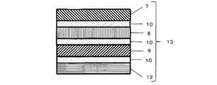
本発明の光反射フィルムは、上記の方法で作製した光反射層PRL−1、PRL−2、PRL−3のうち、1つ以上を含んでいる。各光反射層の半値幅が広い場合は、光反射層PRL−1、PRL−2、PRL−3のうちいずれか1層または2層が含まれることにより可視光領域の大部分をカバーできるが、各光反射層の半値幅が狭い場合は、反射させる偏光の多色化を実現するため、光反射層PRL−1、PRL−2、PRL−3の3つ全てを積層させることがより好ましい。例えば、半値幅が100nm以上200nm未満の狭い範囲の場合には、光反射フィルムは、光反射層PRL−1、PRL−2、PRL−3の3層全てを含み、また、半値幅が200nm以上500nm未満の場合には、光反射層PRL−1、PRL−2、PRL−3のうちいずれか1層または2層を含む等、半値幅に応じて光反射層PRL−1、PRL−2、PRL−3の積層数を適宜調整することができる。また、積層する光反射層の中心反射波長は、例えば100〜300nm程度離れている場合には、積層された反射スペクトルが、可視光領域全体、好ましくは400〜700nmの波長領域全体に渡って例えば5%以上、好ましくは10%以上となるように、適度に重なり合うように設計する。光反射層を積層する手段は、特に制限はなく、例えば、光反射層上に直接他の光反射層を積層したり、粘着剤や接着剤からなる接着層を介して間接的に積層する方法等が挙げられる。 The light reflecting film of the present invention includes one or more of the light reflecting layers PRL-1, PRL-2, and PRL-3 produced by the above method. When the half width of each light reflecting layer is wide, most of the visible light region can be covered by including one or two of the light reflecting layers PRL-1, PRL-2, and PRL-3. When the half width of each light reflecting layer is narrow, it is more preferable to laminate all three of the light reflecting layers PRL-1, PRL-2, and PRL-3 in order to realize multicolorization of the polarized light to be reflected. . For example, when the half width is a narrow range of 100 nm or more and less than 200 nm, the light reflecting film includes all three layers of the light reflecting layers PRL-1, PRL-2, and PRL-3, and the half width is 200 nm or more. In the case of less than 500 nm, the light reflecting layers PRL-1, PRL-2, PRL-3, including any one or two of the light reflecting layers PRL-1, PRL-2, PRL-3, etc. The number of layers of PRL-3 can be adjusted as appropriate. Further, when the central reflection wavelength of the light reflection layer to be stacked is, for example, about 100 to 300 nm away, the stacked reflection spectrum is, for example, over the entire visible light region, preferably over the entire wavelength region of 400 to 700 nm. It is designed to be appropriately overlapped so as to be 5% or more, preferably 10% or more. The means for laminating the light reflecting layer is not particularly limited. For example, a method of laminating another light reflecting layer directly on the light reflecting layer or indirectly laminating via an adhesive layer made of an adhesive or an adhesive. Etc.
図2には、本発明の光反射フィルムの構成図の一例が示してある。光反射層PRL−1、PRL−2、PRL−3のそれぞれに対応する光反射層7、8、9を、接着剤または粘着剤からなる接着層10により積層することで本発明の光反射フィルム11を得ることができる。接着層10に用いられる粘着剤としては、アクリル系やゴム系の粘着剤が挙げられるが、接着性や保持力等を調整しやすいアクリル系粘着剤が好ましい。また、接着層10に用いられる接着剤としては、紫外線硬化型樹脂組成物や熱硬化型樹脂組成物、およびこれらの混合物が挙げられる。紫外線硬化型樹脂の場合は、アクリロイル基、あるいはエポキシ基を有するモノマーを複数混合した組成物を光重合開始剤の存在下で、紫外線を照射することにより硬化させて接着させることができる。熱硬化型樹脂組成物の場合は、エポキシ基を有するモノマーを複数混合した組成物を酸触媒の存在下で加熱することにより硬化させて接着することができる。あるいは、アミノ基、カルボキシル基、水酸基を有する複数のモノマーやポリマーからなる組成物をイソシアネート基やメラミンを有する化合物の存在下で加熱することにより硬化させて接着することができる。
In FIG. 2, an example of the block diagram of the light reflection film of this invention is shown. The light reflecting film of the present invention is formed by laminating the
本発明の光反射フィルムは、入射する光の角度によって反射波長が変化する場合がある。例えば、コレステリック液晶層からなる光反射層の場合、中心反射波長λ2は、光反射層の正面方向から傾けていくに従って短波長側へシフトする。このとき、光反射層PRL−1、PRL−2、PRL−3が短波長側へシフトしても、それよりも長波長側にある光反射層が、代わりに反射することで、表示画像の色変化を抑制できるが、大きく傾けた場合は、PRL−3の帯域を反射することができなくなり、表示画像の色、特に赤色表示が不鮮明となって正しい色で映すことができないという問題が発生することがある。こうした現象は、自動車用のフロントガラス全面でHUDを行う場合、運転者から最も離れた助手席側やフロントガラス上方に表示された画像を見る際に起こりうる。そのような場合、中心反射波長が700nm以上950nm以下、好ましくは720nm以上900nm以下、より好ましくは730nm以上900nm以下、さらに好ましくは730nm以上850nm以下であって、中心反射波長での通常光に対する反射率が5%以上25%以下、好ましくは10%以上20%以下、より好ましくは15%以上、20%以下であって、かつ、PRL−1、PRL−2、PRL−3と同じ向きの偏光を反射する特性をもつ光反射層PRL−4をさらに積層することによって改善することができる。
The reflection wavelength of the light reflecting film of the present invention may change depending on the angle of incident light. For example, in the case of a light reflection layer made of a cholesteric liquid crystal layer, the center reflection wavelength λ2 shifts to the short wavelength side as it is tilted from the front direction of the light reflection layer. At this time, even if the light reflection layers PRL-1, PRL-2, and PRL-3 are shifted to the short wavelength side, the light reflection layer on the longer wavelength side instead reflects, thereby reflecting the display image. Although the color change can be suppressed, when tilted greatly, the PRL-3 band cannot be reflected, and the color of the display image, particularly the red display, becomes unclear and cannot be displayed in the correct color. There are things to do. Such a phenomenon can occur when an image displayed on the front passenger seat side or the front windshield furthest away from the driver is viewed when HUD is performed on the entire front windshield for an automobile. In such a case, the central reflection wavelength is 700 nm or more and 950 nm or less, preferably 720 nm or more and 900 nm or less, more preferably 730 nm or more and 900 nm or less, and further preferably 730 nm or more and 850 nm or less, and the reflectance with respect to normal light at the
本発明で用いられる光反射層PRL−4は、中心反射波長が近赤外線領域にあること以外は、他の光反射層PRL−1、PRL−2、PRL−3と同じである。光反射層PRL−4は正面方向では可視光域に反射域を持たないため、透明であるが、光反射層PRL−4を傾けることによって、反射帯域が短波長側へシフトし、可視光域で反射するようになる。その際、光反射層PRL−3の反射帯域にシフトするように中心反射波長を設定することで、斜めから見た場合においても、正面方向と同じ色の画像を見ることができる。 The light reflection layer PRL-4 used in the present invention is the same as the other light reflection layers PRL-1, PRL-2, and PRL-3 except that the central reflection wavelength is in the near infrared region. The light reflection layer PRL-4 is transparent because it does not have a reflection region in the visible direction, but the reflection band shifts to the short wavelength side by tilting the light reflection layer PRL-4, and the visible light region. It will be reflected at. At that time, by setting the central reflection wavelength so as to shift to the reflection band of the light reflection layer PRL-3, an image having the same color as the front direction can be seen even when viewed from an oblique direction.
図3には、光反射層PRL−4を含む本発明の光反射フィルム13の構成が示してある。PRL−4である光反射層12は、接着層10を介して他の光反射層7、8、9と共に積層される。光反射層PRL−4の中心反射波長での通常光に対する反射率は他の光反射層、特にPRL−3と同じにすることが好ましく、反射率5%以上25%以下であることが好ましく、さらに好ましくは、10%以上25%以下、さらに好ましくは、15%以上20%以下程度とするのがよい。また偏光の向きは、一緒に積層した他の光反射層PRL−1、PRL−2、PRL−3と同じ向き、特に光反射層PRL−3と同じ向きにするのがよい。光反射層PRL−4を積層する順番に特に制限はなく、厚さ方向に任意の位置に配置することができる。
In FIG. 3, the structure of the
本発明で用いる光反射層PRL−4は近赤外線領域に反射帯域を持つため、太陽光に対して遮熱効果も有する。従って、光反射層PRL−1、PRL−2、PRL−3のうちの1つ以上と、光反射層PRL−4とを含む本発明の光反射フィルムは、自動車のフロントガラスに用いることで、高い可視光透過率を有しながら、HUDにおける投影画像の視認性を向上させることができるだけでなく、HUDにおける表示画像の角度依存性をも改善し、さらには、遮熱効果により車内の温度の上昇抑制にも寄与することができる。特に、光反射層PRL−1、PRL−2、PRL−3のうち1層のみを用いる場合には、PRL−4をさらに積層することが好ましい。光反射層PRL−1、PRL−2、PRL−3のうちのいずれか1層と、光反射層PRL−4との2層の積層により、少ない積層数で、多色表示及び近赤外領域からのシフトによる可視光反射の補正効果の両方を実現することが可能となる。 Since the light reflection layer PRL-4 used in the present invention has a reflection band in the near infrared region, it also has a heat shielding effect against sunlight. Therefore, the light reflection film of the present invention including one or more of the light reflection layers PRL-1, PRL-2, and PRL-3 and the light reflection layer PRL-4 is used for a windshield of an automobile. While having high visible light transmittance, not only can the visibility of the projected image on the HUD be improved, but also the angle dependency of the display image on the HUD is improved, and further, the temperature inside the vehicle is improved by the heat shielding effect. It can also contribute to the rise suppression. In particular, when only one of the light reflecting layers PRL-1, PRL-2, and PRL-3 is used, it is preferable to further stack PRL-4. Multi-color display and near-infrared region with a small number of layers by stacking any one of the light reflecting layers PRL-1, PRL-2, and PRL-3 and the light reflecting layer PRL-4 It is possible to realize both the correction effect of the visible light reflection by the shift from.
本発明の光反射フィルムを構成する各光反射層の反射帯域は、少ない積層数で効率よく光源からの複数の波長の光を反射させることと、傾斜に伴う短波長シフトによる反射帯域の変化を抑制するために、広い方が好ましく、半値幅で100nm以上、500nm以下、より好ましくは150nm以上、400nm以下、さらに好ましくは150nm以上、350nm以下程度がよい。半値幅が100nm未満になると、傾斜に伴う波長シフトにより、反射波長が光源の波長と大きくずれてしまい、明るさを向上する効果が低下するだけでなく、上記PRL−4のような近赤外領域からのシフトによる可視光反射の補正効果が限定的となる傾向がある。また、半値幅を100nm未満、特に50nm以下に維持したまま反射率を下げることは困難である場合が多い。一方、半値幅が500nmを超えると、反射率が大幅に低下するため、5%以上の反射率を得ることが困難になり、望ましくない。また、例えば、各光反射層において同一材料のコレステリック液晶を使用した場合、各光反射層の半値幅が広ければ反射率が低くなり、半値幅が狭いと反射率が高くなる傾向がある。よって、各光反射層の半値幅を適切に調整することにより、特定の偏光の反射率をより有効に向上させることができる。なお、ここでいう半値幅とは、光反射層の最大反射率の50%に相当する、長波長側の波長と短波長側の波長とで区画された波長の幅のことを意味する。例えば、最大反射率の50%に相当する短波長側の波長が450nm、長波長側の波長が550nmである場合には、半値幅は100nmである。最大反射率の50%に相当する波長は、選択反射領域の最大反射率から選択反射領域以外の反射率の平均値(例えば、350nm〜950nmにおける平均値)を引くことにより、選択反射由来の反射率を基準として求めることができる。例えば、選択反射領域の最大反射率の値が30%で、選択反射率以外の反射率の平均値(反射率のベースライン)が6%である場合、最大反射率の50%に相当する波長は、30%から(30−6)/2を引いた18%の反射率を示す波長を意味する。 The reflection band of each light reflection layer constituting the light reflection film of the present invention reflects light of a plurality of wavelengths from a light source efficiently with a small number of laminations, and changes in the reflection band due to a short wavelength shift accompanying inclination. In order to suppress it, the wider one is preferable, and the full width at half maximum is 100 nm or more and 500 nm or less, more preferably 150 nm or more and 400 nm or less, and further preferably about 150 nm or more and 350 nm or less. When the full width at half maximum is less than 100 nm, the wavelength shift accompanying the tilt causes the reflected wavelength to deviate significantly from the wavelength of the light source, which not only reduces the effect of improving the brightness, but also the near infrared as in the PRL-4. There is a tendency that the correction effect of the visible light reflection due to the shift from the region is limited. In many cases, it is difficult to lower the reflectance while maintaining the half width at less than 100 nm, particularly 50 nm or less. On the other hand, if the half width exceeds 500 nm, the reflectivity is significantly lowered, and it becomes difficult to obtain a reflectivity of 5% or more, which is not desirable. Further, for example, when cholesteric liquid crystal of the same material is used in each light reflecting layer, the reflectance tends to decrease if the half width of each light reflecting layer is wide, and the reflectance tends to increase if the half width is narrow. Therefore, the reflectance of specific polarized light can be improved more effectively by appropriately adjusting the half width of each light reflecting layer. In addition, the half value width here means the width of the wavelength divided by the wavelength of the long wavelength side and the wavelength of the short wavelength side, which corresponds to 50% of the maximum reflectance of the light reflecting layer. For example, when the wavelength on the short wavelength side corresponding to 50% of the maximum reflectance is 450 nm and the wavelength on the long wavelength side is 550 nm, the half width is 100 nm. The wavelength corresponding to 50% of the maximum reflectance is obtained by subtracting the average value of the reflectance other than the selective reflection region (for example, the average value at 350 nm to 950 nm) from the maximum reflectance of the selective reflection region. It can be determined on the basis of the rate. For example, when the value of the maximum reflectance of the selective reflection region is 30% and the average value of reflectances other than the selective reflectance (reflectance baseline) is 6%, the wavelength corresponding to 50% of the maximum reflectance Means a wavelength exhibiting a reflectance of 18% obtained by subtracting (30-6) / 2 from 30%.
こうして得られた本発明の光反射フィルムを車のフロントガラスのような合わせガラスに挿入し、HUDとして表示する場合、車内側のガラスと車外側のガラスに投影された画像がずれて見える、いわゆるゴースト現象(二重写り)の問題が発生することがある。このようなゴースト現象を改善する方法としては、例えば、図7に示すように本発明の光反射フィルムの一方に、光制御層として1/4波長板23と呼ばれる位相差素子を積層した本発明の光制御フィルム20を用いる方法が好ましい。1/4波長板とは、円偏光を直線偏光に変換する機能を持つ位相差素子であり、例えば、ポリカーボネートやシクロオレフィンポリマーからなるフィルムを位相差が波長の1/4となるように一軸延伸したり、水平配向する重合性液晶を位相差が波長の1/4となるような厚さで配向させたりすることによって得ることができる。この1/4波長板は単独で用いてもよいし、波長分散による位相差のずれが大きい場合には、広帯域1/4波長板と呼ばれる位相差素子を用いてもよい。広帯域1/4波長板とは位相差の波長依存性が低減した位相差素子であり、例えば、同じ波長分散をもつ1/2波長板と1/4波長板とをそれぞれの遅相軸の成す角が60度となるように積層したものや、位相差の波長依存性を低減したポリカーボネート系位相差素子(帝人社製:ピュアエースWR−S)等が挙げられる。さらには、ヘッドアップディスプレイのように、光の入射角が1/4波長板に対して斜めから入射する場合、位相差素子によっては、光の入射角度によって位相差が変化する場合がある。このような場合に、より厳密に位相差を合わせる方法として、例えば、位相差素子の屈折率を調整した位相差素子を用いることにより、入射角に伴う、位相差の変化を抑制することができる。そのような例としては、位相差素子の面内での遅相軸方向の屈折率をnx、面内でnxと直交する方向の屈折率をny、厚さ方向の屈折率をnzとするとき、下記式(2)で示されるNz係数が、好ましくは0.3〜1.0、より好ましくは0.5〜0.8程度となるように制御する。
Nz=(nx−nz)/(nx−ny) (2)When the light reflecting film of the present invention thus obtained is inserted into a laminated glass such as a windshield of a car and displayed as a HUD, the images projected on the vehicle inner glass and the vehicle outer glass appear to be shifted, so-called The problem of ghost phenomenon (double image) may occur. As a method for improving such a ghost phenomenon, for example, the present invention in which a retardation element called a quarter-
Nz = (nx-nz) / (nx-ny) (2)
また、用いる位相差フィルムの遅相軸あるいは進相軸がロール状の1/4波長板の長尺方向に対して45度となっている場合、ロール状の1/4波長板と、同様にロール状の本発明の光反射フィルムとをロールツウロールで積層することにより、ロールの長尺方向に対し、遅相軸あるいは進相軸が45度である本発明の光制御フィルムを得ることができる。さらには、例えば、図8に示すように、図7において光反射フィルムの一方に積層した光制御層としての1/4波長板23とは反対側に、もう一つの光制御層である1/4波長板23をそれぞれの遅相軸あるいは進相軸が直交するように積層することで、光反射フィルムが各々の遅相軸あるいは進相軸が直交した1/4波長板23に挟持された本発明の光制御フィルム24を得ることができる。本発明のHUDの画像表示手段からの出射光がP偏光である場合、車のフロントガラスに本発明の機能性ガラスを用いるためには、1/4波長板の遅相軸あるいは進相軸がP偏光に対して、45度とならなければならない。ロール状の光反射フィルムに対して、1/4波長板の遅相軸あるいは進相軸が0度もしくは90度となるように積層すると、所望の大きさに切り出す時に、ロールの長尺方向に対して45度となるようにしなければならないため、使用できない部分が多数発生してしまい、歩留りを低下させてしまう。しかしながら、上述したように、ロールの長尺方向に対して、1/4波長板の遅相軸あるいは進相軸が45度となるような積層方法を用いることで、ロール状の本発明の光制御フィルムの長尺方向と平行あるいは直交方向に所望の大きさで切り出すことができるため、歩留りが大幅に向上し、本発明の光学フィルムあるいは機能性ガラスを効率的に得ることができる。なお、ここでいうP偏光とは、本発明の光反射フィルム、光制御フィルム、光学フィルム、機能性ガラスといった対象物に入射する光の電気スペクトルの振動方向が入射面内に含まれる直線偏光を意味する。
In addition, when the slow axis or the fast axis of the retardation film to be used is 45 degrees with respect to the longitudinal direction of the roll-shaped quarter wave plate, similarly to the roll-shaped quarter wave plate, By laminating the roll-shaped light reflecting film of the present invention with a roll-to-roll, the light control film of the present invention having a slow axis or a fast axis of 45 degrees with respect to the longitudinal direction of the roll can be obtained. it can. Further, for example, as shown in FIG. 8, another
また、ロール状の1/4波長板とロール状の本発明の光反射フィルムとをロールツウロールで積層する以外にも、1/4波長板上に直接光反射層を積層してもよい。1/4波長板上に直接光反射層が積層されることにより、ラビングなどの配向処理無しにヘーズ値の低い光反射層を得ることができる。このような場合、コレステリック液晶との優れた密着性および偏光に対する反射率の向上の観点から、重合性液晶から作製した1/4波長板の使用が特に好ましい。 Moreover, you may laminate | stack a light reflection layer directly on a quarter wavelength plate besides laminating | stacking a roll-shaped quarter wavelength plate and the roll-shaped light reflection film of this invention with a roll-to-roll. By laminating the light reflection layer directly on the quarter-wave plate, a light reflection layer having a low haze value can be obtained without an alignment treatment such as rubbing. In such a case, the use of a quarter-wave plate made of a polymerizable liquid crystal is particularly preferable from the viewpoint of excellent adhesion with a cholesteric liquid crystal and an improvement in reflectance with respect to polarized light.
ゴースト現象を低減する他の方法としては、例えば、図9に示すように本発明の光反射フィルムの一方に、光制御層として光吸収層21をさらに設けた本発明の光制御フィルム22を用いる方法が挙げられる。光吸収層21により、積層した光反射層PRL−1、PRL−2、PRL−3を透過した光が、ガラスで反射する前に吸収されることによりゴースト現象が低減される。光を吸収する方法は特に限定されないが、例えば、色素をアクリル樹脂等に混合させて光反射層上に塗布する方法や、偏光フィルムを用いる方法が挙げられる。車のフロントガラスに光吸収層を用いる場合は、透過率が合わせガラスとして70%以上であることが法規的に求められるため、光吸収層の透過率も70%以上90%以下、より好ましくは75%以上85%以下程度がよい。このように本発明の光反射層に1/4波長板や光吸収層を新たに積層した本発明の光制御フィルムを、車のフロントガラスとして合わせガラスにする際に、1/4波長板あるいは光吸収層が車外側に配置されるように用いることで、ゴースト現象を低減することが可能となる。但し、画像表示手段からの出射光がP偏光である場合は、本発明の光制御フィルムを車のフロントガラスとして合わせガラスにする際に、当該光制御フィルムの1/4波長板の遅相軸あるいは進相軸がP偏光に対して、HUDにおける投影画像が明るくなるような向きの45度となるように、かつ、車内側に1/4波長板が配置されるように用いるのが望ましい。この1/4波長板の軸配置を誤ると本発明の効果が十分に発現しなくなるため、軸配置は実際に画像を投影し、本発明の効果が十分発揮される軸配置を確認してから合わせガラスを作製することが好ましい。
As another method for reducing the ghost phenomenon, for example, as shown in FIG. 9, the
こうして得られた本発明の光反射フィルムもしくは光制御フィルムを、2枚の中間膜によってラミネートすることで本発明の光学フィルムを得ることができる。図4には、本発明の光学フィルムの一例が示されており、光学フィルム16は、光反射フィルムもしくは光制御フィルム14が2枚の中間膜15により挟持された構成をなし、光反射フィルム14は、例えば、図2の光反射フィルム11または図3の光反射フィルム13に相当し、光制御フィルム14は、例えば、図7の光制御フィルム20、図8の光制御フィルム24または図9の光制御フィルム22に相当する。中間膜としては、ポリビニルブチラール系樹脂(PVB)、あるいはエチレン−酢酸ビニル共重合系樹脂(EVA)を用いることができる。これらは合わせガラス用中間膜として汎用的であるために好ましく、合わせガラスとしての品質をニーズに整合し得るようなものであれば、特に限定されるものではない。
The optical film of the present invention can be obtained by laminating the light reflecting film or the light control film of the present invention thus obtained with two intermediate films. FIG. 4 shows an example of the optical film of the present invention. The
中間膜には、紫外線吸収剤、抗酸化剤、帯電防止剤、熱安定剤、着色剤、接着調整剤等が適宜添加配合されていてもよく、とりわけ、赤外線を吸収する微粒子が分散された中間膜は、高性能な遮熱合わせガラスを作製する上で重要である。赤外線を吸収する微粒子には、Sn、Ti、Zn、Fe、Al、Co、Ce、Cs、In、Ni、Ag、Cu、Pt、Mn、Ta、W、V、Moの金属、酸化物、窒化物あるいはSbやFをドープした各単独物、もしくはこれらの中から少なくとも2種以上を含む複合物などの導電性を有する材料の超微粒子を用いる。特に可視光線の領域では透明である錫ドープ酸化インジウム(ITO)、アンチモンドープ酸化錫(ATO)、フッ素ドープ酸化錫が、特に透明性が求められる建築用や自動車用の窓として用いる場合には、特に好ましい。中間膜に分散させる赤外線を吸収する微粒子の粒径は、0.2μm以下にするのが好ましい。このサイズであれば可視光線の領域での光の散乱を抑制しつつ赤外線を吸収でき、ヘーズを発生させず、電波透過性と透明性を確保しつつ、接着性、透明性、耐久性等の物性を未添加の中間膜と同等に維持し、さらには通常の合わせガラス製造ラインでの作業で合わせガラス化処理を行うことができる。なお、中間膜にPVBを用いる場合には、中間膜の含水率を最適に保つために、恒温恒湿の部屋で合わせ化処理を行う。また、中間膜には、その一部が着色したもの、遮音機能を有する層をサンドイッチしたもの、HUDにおけるゴースト現象(二重写り)を軽減するため、膜厚に傾斜があるもの(楔形)などが使用できる。 The interlayer film may be appropriately added and blended with an ultraviolet absorber, an antioxidant, an antistatic agent, a heat stabilizer, a colorant, an adhesion regulator, etc., and in particular, an intermediate in which fine particles that absorb infrared rays are dispersed. The film is important for producing a high-performance heat-shielding laminated glass. The fine particles that absorb infrared rays include Sn, Ti, Zn, Fe, Al, Co, Ce, Cs, In, Ni, Ag, Cu, Pt, Mn, Ta, W, V, Mo metal, oxide, and nitriding. Or ultrafine particles of a conductive material such as a single substance doped with Sb or F, or a composite containing at least two of them. In particular, when tin-doped indium oxide (ITO), antimony-doped tin oxide (ATO), and fluorine-doped tin oxide, which are transparent in the visible light region, are used as architectural and automotive windows that require transparency, Particularly preferred. The particle diameter of the fine particles that absorb infrared rays dispersed in the intermediate film is preferably 0.2 μm or less. If it is this size, it can absorb infrared rays while suppressing light scattering in the visible light region, does not generate haze, secures radio wave transparency and transparency, and has adhesiveness, transparency, durability, etc. The physical properties can be maintained at the same level as the non-added intermediate film, and further, the laminated glass can be formed by an operation on a normal laminated glass production line. In addition, when PVB is used for the intermediate film, in order to keep the moisture content of the intermediate film optimal, the combination process is performed in a constant temperature and humidity room. In addition, the intermediate film is partially colored, sandwiched with a layer having a sound insulation function, or has a thickness gradient (wedge shape) to reduce the ghost phenomenon (double image) in HUD Can be used.
中間膜によって光反射フィルムもしくは光制御フィルムをラミネートする方法は特に制限はないが、例えば、ニップロールを用いて、中間膜、光反射フィルムもしくは光制御フィルム、中間膜を同時に圧着によりラミネートする方法が挙げられる。ラミネートする際にニップロールが加熱できる場合は、加熱しながら圧着することも可能である。また、中間膜と光反射フィルムとの密着性が劣る場合は、コロナ処理やプラズマ処理などによる表面処理を予め行ってからラミネートしてもよい。 The method of laminating the light reflection film or the light control film with the intermediate film is not particularly limited, but for example, a method of laminating the intermediate film, the light reflection film or the light control film, and the intermediate film simultaneously by pressure bonding using a nip roll is mentioned. It is done. When the nip roll can be heated at the time of laminating, it is possible to perform pressure bonding while heating. Moreover, when the adhesiveness of an intermediate film and a light reflection film is inferior, you may laminate after performing surface treatment by a corona treatment, a plasma treatment, etc. previously.
本発明の光反射フィルム、光制御フィルムまたは光学フィルムをガラスと組み合わせることで、本発明の機能性ガラスを得ることができる。本発明の光反射フィルム、光制御フィルムまたは光学フィルムをガラスに貼り合わせる方法としては、粘着剤もしくは接着剤を該光反射フィルム、光制御フィルムまたは光学フィルムの片側あるいは両側に塗布し、次いで、ガラス板を貼り合わせることによって得ることができる。粘着剤や接着剤には特に制限はないが、後に剥がすことがある場合は、リワーク性に優れた粘着性がよく、例えばシリコーン粘着剤やアクリル系粘着剤等が好ましい。 The functional glass of the present invention can be obtained by combining the light reflecting film, the light control film or the optical film of the present invention with glass. As a method of laminating the light reflecting film, light control film or optical film of the present invention to glass, an adhesive or adhesive is applied to one side or both sides of the light reflecting film, light control film or optical film, and then glass It can be obtained by laminating plates. Although there is no restriction | limiting in particular in an adhesive and an adhesive agent, When peeling off later, the adhesiveness excellent in rework property is good, for example, a silicone adhesive, an acrylic adhesive, etc. are preferable.
本発明の光学フィルムを用いる場合は、2枚のガラス板の間に、該光学フィルムを配置し、高温・高圧にて圧着することにより合わせガラス内に光学フィルムが配置した本発明の機能性ガラスを得ることができる。図5には、本発明の機能性ガラスの一例を示している。図5に示す機能性ガラス18は、光学フィルム16が、2枚のガラス17により挟持された構成をなす。この時、光反射フィルムもしくは光制御フィルム14が挟持されている光学フィルム16における中間膜15は、ガラス17と光反射フィルムとの密着性を保持するための粘着剤もしくは接着剤としての機能も有する。
When the optical film of the present invention is used, the functional glass of the present invention in which the optical film is disposed in the laminated glass is obtained by disposing the optical film between two glass plates and press-bonding at a high temperature and high pressure. be able to. FIG. 5 shows an example of the functional glass of the present invention. The
上記光学フィルム16を用いて本発明の機能性ガラスを作製する方法の一例を具体的に説明する。まず、2枚のガラス板を準備する。自動車のフロントガラス用の合わせガラスとして用いる場合は、フロート法で作られたソーダライムガラスを使用する。ガラスは透明、緑色に着色されたもの、いずれでもよく、特に制限はない。これらのガラス板の厚さは、通常、約2mmtのものを使用するが、近年のガラスの軽量化の要求に応じて、これよりも若干薄い厚さのガラス板も使用できる。ガラス板を所定の形状に切り出し、ガラスエッジに面取りを施し洗浄する。黒色の枠状やドット状のプリントが必要な際には、ガラス板にこれを印刷する。フロントガラスのように曲面形状が必要とされる場合には、ガラス板を650℃以上に加熱し、その後、モールドによるプレスや自重による曲げなどで2枚が同じ面形状となるように整形し、ガラスを冷却する。このとき、冷却速度を早くしすぎると、ガラス板に応力分布が生じて強化ガラスとなるために、徐冷する。このように作製したガラス板のうちの1枚を水平に置き、その上に本発明の光学フィルムを重ね、さらにもう一方のガラス板を置く。あるいは、ガラス板の上に中間膜、本発明の光反射フィルムもしくは光制御フィルム、中間膜を順に重ね、最後にもう一方のガラス板を置くといった方法でもよい。このとき、本発明の光制御フィルムを用いる場合は、光制御層としての1/4波長板や光吸収層は、車外側になるように配置する。次いで、ガラスのエッジからはみ出した光学フィルムや中間膜、光反射フィルムは、カッターで切断・除去する。その後、サンドイッチ状に積層したガラス、中間膜、光反射フィルムもしくは光制御フィルムとの間に存在する空気を脱気しながら温度80℃から100℃に加熱し、予備接着を行う。空気を脱気する方法にはガラス/中間膜/光反射フィルムもしくは光制御フィルム/中間膜/ガラスの積層物を耐熱ゴムなどでできたゴムバッグで包んで行うバッグ法と、ガラスの端部のみをゴムリングで覆ってシールするリング法の2種があり、どちらの方法を用いてもよい。予備接着が終了後、ゴムバッグから取り出したガラス/中間膜/光反射フィルムもしくは光制御フィルム/中間膜/ガラスの積層物、もしくはゴムリングを取り外した積層物をオートクレーブに入れ、10〜15kg/cm2の高圧下で、120℃〜150℃に加熱し、この条件で20分〜40分間、加熱・加圧処理する。処理後、50℃以下に冷却したのちに除圧し、ガラス/中間膜/光反射フィルムもしくは光制御フィルム/中間膜/ガラスからなる本発明の機能性ガラスをオートクレーブから取り出す。An example of a method for producing the functional glass of the present invention using the
こうして得られた本発明の機能性ガラスは、普通自動車、小型自動車、軽自動車などともに、大型特殊自動車、小型特殊自動車のフロントガラス、サイドガラス、リアガラス、ルーフガラスとして使用できる。さらには、鉄道車両、船舶、航空機の窓としても、また、建材用および産業用の窓材としても使用できる。使用の形態であるが、UVカットや調光機能を有する部材と、積層あるいは貼合して用いることができる。 The functional glass of the present invention thus obtained can be used as a front glass, a side glass, a rear glass and a roof glass for large special automobiles, small special automobiles, as well as ordinary automobiles, small automobiles, light automobiles and the like. Furthermore, it can also be used as a window for railway vehicles, ships and aircraft, and as a window material for building materials and industrial use. Although it is a form of use, it can be used by laminating or bonding with a member having a UV cut or dimming function.
さらに、本発明の機能性ガラス18を図1のフロントガラス4と置き換えるか、あるいは本発明の光反射フィルムまたは光制御フィルムをフロントガラスの車内側ガラスに貼り付けることで、本発明のヘッドアップディスプレイ(HUD)を得ることができる。光反射層がコレステリック液晶層からなる場合は、図6における画像表示手段2からは直線偏光もしくは円偏光を出射させることにより、本発明の効果を得ることができ、特に円偏光の方がより高い反射率を得ることができる。円偏光出射手段としては、具体的には、図6に示すように、光反射層がコレステリック液晶層からなる本発明の機能性ガラス18に対し、画像表示手段2から出射される光が直線偏光である場合には、1/4波長板19を画像表示手段2と反射鏡3との間、もしくは反射鏡3と機能性ガラス18との間もしくは光反射層と車内側の中間膜との間に配置し、さらに、直線偏光の偏光軸に対して、光反射層であるコレステリック液晶層が反射する円偏光と同じ向きの円偏光となるように1/4波長板19の進相軸または遅相軸を合わせることにより、画像表示手段2から出射された光は、本発明の機能性ガラス18に到達するまでに円偏光となり、機能性ガラス内のコレステリック液晶層によって反射することにより、観察者1へ到達する。
Furthermore, the
本発明の効果は、上記構成に限定されない。例えば、光制御層としての1/4波長板を本発明の光反射層と積層した本発明の光制御フィルムを、1/4波長板が車内側になるように、なおかつ、1/4波長板の遅相軸または進相軸が投影されるP偏光に対してHUDにおける投影画像が明るくなるような向きの45度となるように配置されるように用い本発明の機能性ガラスを作製する。次に画像表示手段からの出射光をP偏光とし、さらにブリュースター角近傍で本発明の機能性ガラスへ入射して投影させると、車内側のガラスでの反射は大幅に低減され、透過した光は、1/4波長板で円偏光となって光反射層で反射し、再び1/4波長板でP偏光となって観察者へ明るい画像を投影することができる。上記の構成において本発明の機能性ガラスを使用した場合、HUDの投影画像を見た際に発生するゴースト現象を、大幅に軽減させることができる。さらに、偏光サングラスをかけて投影画像を見ることにより、投影画像の視認性は高いまま、かつ、ゴースト現象をほとんど消失させることができる。通常のHUDシステムは、P偏光の反射率が低いため、S偏光を利用する。また、路面の反射はS偏光であることから、偏光サングラスは、S偏光を吸収できるように偏光軸が設計されている。従って、偏光サングラスをかけて通常のHUDの投影画像を見ると、投影画像の視認性は極端に低下してしまう。一方、本発明の光制御フィルムを用いて、上記の如くP偏光の反射率を向上させたHUD、すなわち、P偏光を利用したHUDを作製することで、HUDの投影画像の視認性を高め、ゴースト現象を低減し、かつ、偏光サングラス着用時においても、投影画像の視認性は高く、ゴースト現象をほぼ解消できるという極めて優れた効果を得ることができる。 The effect of the present invention is not limited to the above configuration. For example, the light control film of the present invention in which a quarter wave plate as a light control layer is laminated with the light reflection layer of the present invention is used so that the quarter wave plate is on the vehicle interior and the quarter wave plate The functional glass of the present invention is produced so as to be arranged at 45 degrees so that the projected image on the HUD becomes brighter with respect to the P-polarized light whose slow axis or fast axis is projected. Next, when the emitted light from the image display means is converted to P-polarized light and then incident and projected onto the functional glass of the present invention in the vicinity of the Brewster angle, the reflection on the glass inside the vehicle is greatly reduced, and the transmitted light Can be circularly polarized by the quarter wave plate and reflected by the light reflecting layer, and can be again P polarized by the quarter wave plate to project a bright image to the viewer. When the functional glass of the present invention is used in the above configuration, the ghost phenomenon that occurs when viewing the projected image of the HUD can be greatly reduced. Furthermore, by viewing the projection image with polarized sunglasses, the visibility of the projection image remains high and the ghost phenomenon can be almost eliminated. A normal HUD system uses S-polarized light because of the low reflectance of P-polarized light. Further, since the reflection on the road surface is S-polarized light, the polarization axis of the polarized sunglasses is designed so that S-polarized light can be absorbed. Therefore, when a normal HUD projection image is viewed while wearing polarized sunglasses, the visibility of the projection image is extremely reduced. On the other hand, by using the light control film of the present invention to improve the reflectance of P-polarized light as described above, that is, by making a HUD using P-polarized light, the visibility of the projected image of the HUD is improved. The ghost phenomenon is reduced, and even when wearing polarized sunglasses, the visibility of the projected image is high, and an extremely excellent effect that the ghost phenomenon can be almost eliminated can be obtained.
さらに、本発明の機能性ガラス内にある光反射フィルムが、近赤外線領域を反射する光反射層PRL−4をさらに含む場合、HUDにおける角度依存性を解消し、観察者がフロントガラスを斜め方向から観察しても、PRL−4が反射波長域を近赤外線領域から可視光の赤色領域へとシフトさせるため、正面方向と同じ表示色を見ることが可能となる。さらには、光反射層PRL−4は、遮熱効果もあるために、太陽光入射による車内の温度上昇抑制にも寄与できる。 Furthermore, when the light reflecting film in the functional glass of the present invention further includes a light reflecting layer PRL-4 that reflects the near infrared region, the angle dependency in the HUD is eliminated, and the observer tilts the windshield in an oblique direction. Even if observed, the PRL-4 shifts the reflection wavelength region from the near infrared region to the red region of visible light, so that the same display color as the front direction can be seen. Furthermore, since the light reflection layer PRL-4 also has a heat shielding effect, it can contribute to the suppression of the temperature rise in the vehicle due to the incidence of sunlight.
本発明の光制御フィルムを、光反射層の車外側に光制御層として1/4波長板が積層されるように配置した場合には、光反射層を通過した円偏光は、1/4波長板により直線偏光に変換される。このとき、直線偏光がP偏光となるように1/4波長板の遅相軸または進相軸を調整して変換し、さらに、車外側のガラスへの入射角をブリュースター角あるいはその近傍になるように光路を調整することで、車外側ガラスでの反射率を大幅に低減することができるため、ゴースト現象が改善される。この時、入射光を円偏光にする手段として、光反射層と車内側の中間膜との間に光制御層として1/4波長板を配置する場合は、光反射層が2枚の1/4波長板に挟持された構成となる。これも本発明の光制御フィルムの一実施形態である。この時、2枚の1/4波長板の遅相軸は直交するように配置することが好ましく、より好ましくは、2枚の1/4波長板の遅相軸は直交するように、かつ、入射するP偏光に対して45度となるように配置するのがよい。このように配置することで、例えば、投射する光をP偏光とし、さらにブリュースター角近傍で本発明の合わせガラスへ入射させると、車内側のガラスでの反射は大幅に低減され、車内側のガラスを透過した光は、1/4波長板で円偏光となって光反射層で反射し、再び1/4波長板でP偏光となって観察者へ明るい画像を投影することができる。また、光反射層を通過した光は、車外側にある1/4波長板によりP偏光となり、車内側と同様にブリュースター角近傍であるために車外側のガラスでの反射を大幅に低減することができる。このことは、合わせガラスにおける車内側、車外側それぞれで発生するゴースト現象を改善し、投影された画像の視認性を向上させることができるため、特に好ましい。以上のように観察される光が円偏光、もしくはP偏光にすることにより、偏光サングラスをかけていても投影画像が暗くなることを防ぐことができるので好ましく、より好ましくはP偏光とするのがよい。 When the light control film of the present invention is arranged such that a quarter-wave plate is laminated as a light control layer on the vehicle exterior side of the light reflection layer, the circularly polarized light that has passed through the light reflection layer is a quarter wavelength. It is converted into linearly polarized light by the plate. At this time, conversion is performed by adjusting the slow axis or the fast axis of the quarter-wave plate so that the linearly polarized light becomes P-polarized light, and the incident angle to the glass on the outside of the vehicle is set at or near the Brewster angle. By adjusting the optical path in such a manner, the reflectance at the vehicle exterior glass can be greatly reduced, so that the ghost phenomenon is improved. At this time, when a quarter wavelength plate is disposed as a light control layer between the light reflection layer and the intermediate film on the vehicle interior as means for converting the incident light into circularly polarized light, the light reflection layer has two 1 / The structure is sandwiched between four wavelength plates. This is also an embodiment of the light control film of the present invention. At this time, it is preferable to arrange so that the slow axes of the two quarter-wave plates are orthogonal, more preferably so that the slow axes of the two quarter-wave plates are orthogonal, and It is preferable to arrange it at 45 degrees with respect to the incident P-polarized light. By arranging in this way, for example, when the light to be projected is P-polarized light and incident on the laminated glass of the present invention in the vicinity of the Brewster angle, reflection on the glass inside the vehicle is greatly reduced, The light transmitted through the glass becomes circularly polarized light by the quarter wavelength plate and reflected by the light reflecting layer, and again becomes P polarized light by the quarter wavelength plate, and a bright image can be projected to the observer. In addition, the light that has passed through the light reflecting layer becomes P-polarized light by the quarter wavelength plate on the outside of the vehicle, and is in the vicinity of the Brewster angle like the inside of the vehicle, so that reflection on the glass on the outside of the vehicle is greatly reduced. be able to. This is particularly preferable because it can improve the ghost phenomenon occurring on the inside and outside of the laminated glass and improve the visibility of the projected image. The light observed as described above is preferably circularly polarized or P-polarized so that the projected image can be prevented from becoming dark even when wearing polarized sunglasses, and more preferably P-polarized. Good.
本発明の光制御フィルムにおいて、光制御層として光吸収層を用いた場合、光反射層の車外側に光吸収層が配置されているため、光反射層を通過した光は、この光吸収層にて吸収されるため、車外側のガラスで反射されることなく、あるいは極めて僅かな反射しかしないため、ゴースト現象を改善することができる。なお、光吸収層を上記光反射層に、光吸収層が上記光反射層の車内側になるように積層した1/4波長板と併用することも可能であり、例えば、1/4波長板によってP偏光となった直線偏光を吸収するように、偏光板との吸収軸をP偏光の偏光軸合わせて1/4波長板のさらに車外側で、かつ、車外側のガラスの内側に光吸収層を配置することにより、さらにゴースト現象を低減することができる。このように光反射フィルムを1/4波長板と光吸収層で挟持するような構成の他に、1/4波長板にて挟持された光制御フィルムの一方にさらに光吸収層を設けた構成も本発明の光制御フィルムの一形態であり、これらの光制御フィルムの光吸収層が車外側になるように配置して合わせガラス、およびHUDを作製することにより、上記のブリュースター角近傍からのP偏光入射によるゴースト現象の改善効果と光吸収層による透過した光の吸収効果により、ゴースト現象をさらに低減することが可能となる。 In the light control film of the present invention, when a light absorption layer is used as the light control layer, the light absorption layer is disposed on the vehicle exterior side of the light reflection layer. Therefore, the ghost phenomenon can be improved because it is not reflected by the glass on the outside of the vehicle or has very little reflection. In addition, it is also possible to use together with the quarter wavelength plate which laminated | stacked the light absorption layer on the said light reflection layer so that a light absorption layer might become the vehicle inside of the said light reflection layer, for example, a quarter wavelength plate In order to absorb the linearly polarized light that has become P-polarized light, the absorption axis with the polarizing plate is aligned with the polarization axis of the P-polarized light so that the light is absorbed further outside the quarter wave plate and inside the glass outside the vehicle. The ghost phenomenon can be further reduced by arranging the layers. In addition to the configuration in which the light reflecting film is sandwiched between the quarter wavelength plate and the light absorbing layer in this manner, a configuration in which a light absorbing layer is further provided on one of the light control films sandwiched by the quarter wavelength plate. Is also a form of the light control film of the present invention, and the laminated glass and the HUD are prepared by arranging the light absorption layer of these light control films to be on the outside of the vehicle. The ghost phenomenon can be further reduced by the effect of improving the ghost phenomenon by the incidence of P-polarized light and the effect of absorbing the transmitted light by the light absorption layer.
本発明のHUDにおいて使用される画像表示手段は、最終的に機能性ガラスに到達するまでに、所望の偏光となっていれば特に制限はないが、液晶表示装置(LCD)、有機ELディスプレイ等が挙げられる。画像表示装置が液晶表示装置である場合、出射光は通常直線偏光となっているため、そのまま用いるか、図6のように1/4波長板19を設置して円偏光に変換することが可能である。あるいは自動車の場合は例えばダッシュボードのような光出射口に偏光板や円偏光板、1/4波長板を配置して最適な偏光に調整することも可能である。有機ELの場合は、1/4波長板19と画像表示手段2との間に偏光板を配置すればよい。あるいは上記液晶ディスプレイと同様に、光出射口に偏光板や円偏光板、1/4波長板を配置して最適な偏光に調整すればよい。また使用される光源もレーザー光源やLED光源等特に制限はない。本発明で用いる光反射層において、これら光源の発光スペクトルに対応するように中心反射波長を設定することで、より効果的に表示画像を明るく投影できる。 The image display means used in the HUD of the present invention is not particularly limited as long as it has a desired polarization before finally reaching the functional glass, but a liquid crystal display (LCD), an organic EL display, etc. Is mentioned. When the image display device is a liquid crystal display device, the emitted light is usually linearly polarized light, so it can be used as it is or can be converted into circularly polarized light by installing a quarter wavelength plate 19 as shown in FIG. It is. Alternatively, in the case of an automobile, for example, a polarizing plate, a circularly polarizing plate, and a ¼ wavelength plate can be arranged at a light exit port such as a dashboard to adjust to an optimum polarization. In the case of organic EL, a polarizing plate may be disposed between the quarter wavelength plate 19 and the image display means 2. Or like the said liquid crystal display, what is necessary is just to arrange | position a polarizing plate, a circularly-polarizing plate, and a quarter wavelength plate to a light-projection port, and just to adjust to an optimal polarization. The light source used is not particularly limited, such as a laser light source or an LED light source. In the light reflection layer used in the present invention, the display image can be projected more effectively by setting the center reflection wavelength so as to correspond to the emission spectrum of these light sources.
以下、実施例により、本発明を詳細に例示する。実施例において部は重量部を意味する。 Hereinafter, the present invention will be illustrated in detail by examples. In the examples, parts means parts by weight.
塗布液(液晶組成物)の調製
下記表に示す組成の塗布液(R1)、(R2)、(R3)、(R4)をそれぞれ調製した。Preparation of coating liquid (liquid crystal composition) Coating liquids (R1), (R2), (R3), and (R4) having the compositions shown in the following table were prepared.
塗布液(R1)の組成表

次に、塗布液(R1)のカイラル剤の処方量を下表に示す量に変更する以外は同様の処方にて塗布液(R2)、(R3)、(R4)を調整した。 Next, coating solutions (R2), (R3), and (R4) were prepared in the same manner except that the amount of the chiral agent in coating solution (R1) was changed to the amount shown in the table below.
[実施例1]
<光反射フィルムの作製>
調製した塗布液(R1)、(R2)、(R3)を用い、下記の手順にてそれぞれ光反射層PRL−1、光反射層PRL−2、光反射層PRL−3を作製し、次いでそれらを積層して本発明の光反射フィルムを作製した。プラスチック基板としては、特開2002−90743号公報の実施例1に記載された方法で下塗り層無し面を予めラビング処理した東洋紡績社製PETフィルム(商品名 A4100、厚さ50μm)を使用した。[Example 1]
<Production of light reflecting film>
Using the prepared coating liquids (R1), (R2), and (R3), the light reflecting layer PRL-1, the light reflecting layer PRL-2, and the light reflecting layer PRL-3 were respectively produced by the following procedure, and then Were laminated to prepare a light reflecting film of the present invention. As the plastic substrate, a PET film (trade name: A4100, thickness: 50 μm) manufactured by Toyobo Co., Ltd. was used in which the surface without the undercoat layer was previously rubbed by the method described in Example 1 of JP-A-2002-90743.
(1)各塗布液を、ワイヤーバーを用いて、乾燥後にそれぞれ得られる各光反射層の厚みが0.5μmになるように、各PETフィルムのラビング処理面上に室温にて塗布した。
(2)各塗布膜を、150℃にて5分間加熱して溶剤を除去するとともに、コレステリック液晶相とした。次いで、高圧水銀ランプ(ハリソン東芝ライティング社製)を120W出力、5〜10秒間UV照射し、コレステリック液晶相を固定して、PETフィルム上に光反射層を得た。
(3)(1)〜(2)にて作製した、PETフィルム上の光反射層PRL−1(塗布液(R1)使用)と光反射層PRL−2(塗布液(R2)使用)の光反射層側同士を、アクリル系粘着剤(綜研化学社製、アクリル粘着剤SKダイン906)を用いて積層した。
(4)光反射層PRL−2のPETフィルムを剥離した。
(5)(1)〜(2)と同様に作製したPETフィルム上の光反射層PRL−3(塗布液(R3)使用)の光反射層側と、(4)における光反射層PRL−2のうちPETフィルムを剥離させた光反射層側同士を、(3)と同じアクリル系粘着剤を用いて積層した。
(6)最後に、積層した光反射層PRL−1と、PRL−3の両外側にあるPETフィルムを剥離した。(1) Each coating solution was applied on the rubbing-treated surface of each PET film at room temperature using a wire bar so that the thickness of each light reflection layer obtained after drying was 0.5 μm.
(2) Each coating film was heated at 150 ° C. for 5 minutes to remove the solvent and make a cholesteric liquid crystal phase. Subsequently, a high pressure mercury lamp (manufactured by Harrison Toshiba Lighting Co., Ltd.) was irradiated with UV at 120 W for 5 to 10 seconds to fix the cholesteric liquid crystal phase to obtain a light reflecting layer on the PET film.
(3) Light of the light reflecting layer PRL-1 (using the coating liquid (R1)) and the light reflecting layer PRL-2 (using the coating liquid (R2)) on the PET film prepared in (1) to (2) The reflective layer sides were laminated using an acrylic pressure-sensitive adhesive (manufactured by Soken Chemical Co., Ltd., acrylic pressure-sensitive adhesive SK Dyne 906).
(4) The PET film of the light reflection layer PRL-2 was peeled off.
(5) The light reflecting layer PRL-3 (using the coating liquid (R3)) on the PET film prepared in the same manner as (1) to (2), and the light reflecting layer PRL-2 in (4) Among them, the light reflection layer sides from which the PET film was peeled were laminated using the same acrylic pressure-sensitive adhesive as in (3).
(6) Finally, the PET films on both outer sides of the laminated light reflecting layers PRL-1 and PRL-3 were peeled off.
こうして、光反射層PRL−1、光反射層PRL−2、光反射層PRL−3の順序で積層された3層からなる、厚さが1.5μmの本発明の光反射フィルムを得た。図10は、単一の各光反射層PRL−1、PRL−2、PRL−3、PRL−4を形成したときに波長と反射率の関係をプロットした図である。光反射層PRL−1、PRL−2、PRL−3の中心反射波長は、図10および下記の表3からもわかるように、それぞれ450nm(半値幅は123nm)、540nm(半値幅は131nm)、650nm(半値幅は148nm)であり、かつ光反射層PRL−1、PRL2、PRL−3の中心反射波長における反射率は、それぞれ約20%、約21%、約22%であった。 In this way, the light reflecting film of the present invention having a thickness of 1.5 μm composed of three layers laminated in the order of the light reflecting layer PRL-1, the light reflecting layer PRL-2, and the light reflecting layer PRL-3 was obtained. FIG. 10 is a diagram in which the relationship between the wavelength and the reflectance is plotted when each of the single light reflection layers PRL-1, PRL-2, PRL-3, and PRL-4 is formed. The central reflection wavelengths of the light reflection layers PRL-1, PRL-2, and PRL-3 are 450 nm (half-value width is 123 nm) and 540 nm (half-value width is 131 nm), as can be seen from FIG. 10 and Table 3 below. The reflectivity at the central reflection wavelength of the light reflection layers PRL-1, PRL2, and PRL-3 was about 20%, about 21%, and about 22%, respectively.
得られた光反射フィルムの透過率と反射率の分光特性を図11に示した。光反射フィルムの正面方向における可視光の平均透過率は、約77%であり、一般に視感度の高い550nm付近における反射率は、約23%であった。一方、得られた光反射フィルムを正面から50°傾けた位置から見ると、赤色領域(650nm付近)の透過率が上昇し、正面方向とは異なる色味となった。 The spectral characteristics of transmittance and reflectance of the obtained light reflecting film are shown in FIG. The average transmittance of visible light in the front direction of the light reflecting film was about 77%, and the reflectance around 550 nm, which is generally high in visual sensitivity, was about 23%. On the other hand, when the obtained light reflecting film was viewed from a position inclined by 50 ° from the front, the transmittance in the red region (near 650 nm) increased, and the color different from the front direction.
<光学フィルムの作製>
厚さが0.38mmの透明なポリビニルブチラール中間膜を2枚用い、上記本発明の光反射フィルムをポリビニルブチラールフィルム間に配置し、次いで、ラミネーターにて加圧圧着することにより、本発明の光学フィルムを得た。<Production of optical film>
By using two transparent polyvinyl butyral interlayers with a thickness of 0.38 mm, the light reflecting film of the present invention is placed between the polyvinyl butyral films, and then pressure-pressed with a laminator, the optical of the present invention A film was obtained.
<機能性ガラスの作製>
1枚の厚さが2mmのガラス板2枚の間に、上記光学フィルムを配置し、次いで、加圧・加熱することにより、本発明の機能性ガラスを得た。まず、透明なガラス板上に、上記本発明の光学フィルム、透明なガラス板を重ねた。次にガラス板のエッジ部からはみ出した光学フィルムの余分な部分を切断・除去した。これをゴムバッグで包み、90℃に加熱したオートクレーブ中で10分間脱気し、予備接着した。これを室温まで冷却後、ゴムバッグから取り出し、再度、オートクレーブ中で135℃、12kg/cm2の高圧下で30分間加熱・加圧し、外観が良好な本発明の光学フィルムを挿入した本発明の機能性ガラスを作製した。得られた本発明の機能性ガラスの可視光透過率は72%であった。<Production of functional glass>
The functional glass of the present invention was obtained by placing the optical film between two glass plates each having a thickness of 2 mm, and then applying pressure and heating. First, the optical film of the present invention and a transparent glass plate were stacked on a transparent glass plate. Next, the excess part of the optical film which protruded from the edge part of the glass plate was cut and removed. This was wrapped in a rubber bag, degassed for 10 minutes in an autoclave heated to 90 ° C., and pre-adhered. After cooling this to room temperature, it is taken out from the rubber bag and again heated and pressurized in an autoclave at 135 ° C. under a high pressure of 12 kg / cm 2 for 30 minutes, and the optical film of the present invention having a good appearance is inserted. Functional glass was produced. The functional glass of the present invention obtained had a visible light transmittance of 72%.
<ヘッドアップディスプレイの作製および表示画像の評価>
図6に示すような配置でヘッドアップディスプレイを作製した。なお、画像表示手段2としては液晶プロジェクター、1/4波長板19としては、高帯域1/4波長板(帝人社製:ピュアエースWR−S)、反射鏡3は市販の鏡を用い、機能性ガラス18は、上記で作製した合わせガラスを用いた。次に、暗室内にて、液晶プロジェクターから、機能性ガラスへ画像を投影したところ、表示画像は極めて明るく鮮明に投影された。一方、観察位置を斜め方向(正面方向から約50度)に傾けたところ、表示画像の赤色表示がやや不鮮明であった。<Preparation of head-up display and evaluation of display image>
A head-up display was produced in an arrangement as shown in FIG. The image display means 2 is a liquid crystal projector, the quarter-wave plate 19 is a high-band quarter-wave plate (manufactured by Teijin Limited: Pure Ace WR-S), and the
[実施例2]
塗布液(R4)を用いたこと以外は、実施例1と同様の作製法により、PETフィルム上に光反射層PRL−4(塗布液(R4)使用)を得た。実施例1の(1)〜(5)により得られた光反射フィルムの光反射層PRL−3側にあるPETフィルムを剥離し、PETフィルム上の光反射層PRL−4の光反射層側と、光反射層PRL−3のうちPETフィルムを剥離させた光反射層側同士を、アクリル系粘着剤を用いて積層し、次いで積層した光反射層PRL−1と、光反射層PRL−4の両外側にあるPETフィルムを剥離することにより、光反射層PRL−1、光反射層PRL−2、光反射層PRL−3、光反射層PRL−4の順序で積層された4層からなる本発明の光反射フィルムを得た。光反射層PRL−4の中心反射波長は、図10および表3からもわかるように、800nm(半値幅は178nm)であり、かつ光反射層PRL−4の中心反射波長における反射率は、約20%であった。[Example 2]
Except for using the coating liquid (R4), a light reflecting layer PRL-4 (using the coating liquid (R4)) was obtained on the PET film by the same production method as in Example 1. The PET film on the light reflecting layer PRL-3 side of the light reflecting film obtained by (1) to (5) of Example 1 is peeled off, and the light reflecting layer side of the light reflecting layer PRL-4 on the PET film is removed. Of the light reflection layer PRL-3, the light reflection layer sides from which the PET film was peeled were laminated using an acrylic adhesive, and then the laminated light reflection layer PRL-1 and light reflection layer PRL-4 A book consisting of four layers laminated in the order of the light reflecting layer PRL-1, the light reflecting layer PRL-2, the light reflecting layer PRL-3, and the light reflecting layer PRL-4 by peeling the PET films on both outer sides. An inventive light reflecting film was obtained. As can be seen from FIG. 10 and Table 3, the center reflection wavelength of the light reflection layer PRL-4 is 800 nm (half-value width is 178 nm), and the reflectance at the center reflection wavelength of the light reflection layer PRL-4 is about 20%.
得られた光反射フィルムの透過率と反射率の分光特性を図12に示した。光反射フィルムの正面方向における可視光の平均透過率は約77%であり、550nm付近における反射率は約22%であった。また、得られた光反射フィルムを正面から50°傾けた位置から見ても、赤色領域の透過率の変化はなく、正面方向と同様の色味であった。 FIG. 12 shows the spectral characteristics of the transmittance and reflectance of the obtained light reflecting film. The average transmittance of visible light in the front direction of the light reflecting film was about 77%, and the reflectance around 550 nm was about 22%. Moreover, even if it looked at the obtained light reflection film from the position inclined 50 degrees from the front, there was no change of the transmittance | permeability of a red area | region, and it was the same color as the front direction.
次に、実施例1と同様の作製法により、2枚のポリビニルブチラール中間膜に挟持することにより、本発明の光学フィルムを得た。さらには、実施例1と同様の作製法により、2枚のガラスを用いて本発明の光学フィルムを挟持して合わせガラスとすることにより、本発明の機能性ガラスを得た。得られた本発明の機能性ガラスの可視光透過率は72%であった。次に、実施例1と同様の作製法により、HUDを作製し、同様の評価を行ったところ、正面方向の表示画像は極めて明るく鮮明であった。また、観察位置を斜め方向(正面方向から約50度)に傾けても、表示画像の色は変化がなく、正面方向と同様に鮮明であった。 Next, the optical film of the present invention was obtained by sandwiching it between two polyvinyl butyral interlayers by the same production method as in Example 1. Furthermore, the functional glass of the present invention was obtained by using the two glasses to sandwich the optical film of the present invention into a laminated glass by the same production method as in Example 1. The functional glass of the present invention obtained had a visible light transmittance of 72%. Next, HUD was produced by the same production method as in Example 1, and the same evaluation was performed. As a result, the display image in the front direction was extremely bright and clear. Further, even when the observation position was tilted in an oblique direction (about 50 degrees from the front direction), the color of the display image did not change and was as clear as the front direction.
[実施例3]
実施例2で得られた光反射フィルムの光反射層PRL−4側に、光制御層としての広帯域1/4波長板(帝人社製:ピュアエースWR−S)を粘着剤にて貼り合わせて、本発明の光制御フィルムを得た。この光学フィルムを実施例1と同様の作製法により、2枚のポリビニルブチラール中間膜に挟持することにより、本発明の光学フィルムを得た。さらには、実施例1と同様の作製法により、2枚のガラスを用いて本発明の光学フィルムを1枚の1/4波長板が車外側のガラス側になるように挟持して合わせガラスとすることにより、本発明の機能性ガラスを得た。得られた本発明の機能性ガラスの可視光透過率は72%であった。次に、実施例1と同様の作製法により、HUDを作製し、同様の評価を行ったところ、正面方向の表示画像は極めて明るく鮮明であった。また、観察位置を斜め方向(正面方向から約50度)に傾けても、表示画像の色は変化がなく、正面方向と同様に鮮明であった。さらには、表示画像が明るくなるように、かつ、1/4波長板の遅相軸が45度となるように配置し、表示画像を裸眼にて観察したところ、ゴースト現象が実施例1および2よりも軽減し、表示画像の視認性がさらに向上した。次に、この表示画像を市販の偏光サングラス(吸収軸が地面と水平方向)をかけて観察したところ、ゴーストは大幅に軽減し、表示画像を鮮明に見ることができた。[Example 3]
A wide-band quarter-wave plate (manufactured by Teijin: Pure Ace WR-S) as a light control layer is bonded to the light reflecting layer PRL-4 side of the light reflecting film obtained in Example 2 with an adhesive. The light control film of the present invention was obtained. The optical film of the present invention was obtained by sandwiching this optical film between two polyvinyl butyral interlayers by the same production method as in Example 1. Furthermore, by the same manufacturing method as in Example 1, the optical film of the present invention is sandwiched between two glasses using one glass so that one quarter-wave plate is on the glass side outside the vehicle. Thus, the functional glass of the present invention was obtained. The functional glass of the present invention obtained had a visible light transmittance of 72%. Next, HUD was produced by the same production method as in Example 1, and the same evaluation was performed. As a result, the display image in the front direction was extremely bright and clear. Further, even when the observation position was tilted in an oblique direction (about 50 degrees from the front direction), the color of the display image did not change and was as clear as the front direction. Further, when the display image is brightened and the slow axis of the quarter-wave plate is 45 degrees and the display image is observed with the naked eye, the ghost phenomenon is found in the first and second embodiments. And the visibility of the displayed image is further improved. Next, when this display image was observed with commercially available polarized sunglasses (absorption axis is in the horizontal direction with respect to the ground), the ghost was greatly reduced and the display image could be seen clearly.
[実施例4]
実施例3で得られた光制御フィルムの光反射層PRL−1側に、実施例3で用いた光制御層としての広帯域1/4波長板をそれぞれの1/4波長板の遅相軸が直交に配置されるように同様の方法にてさらに貼り合せ、光反射フィルムを2枚の1/4波長板で挟持した本発明の光制御フィルムを得た。この光学フィルムを実施例1と作製法の操作により、2枚のポリビニルブチラール中間膜に挟持することにより、本発明の光学フィルムを得た。さらには、実施例1と作製法の操作により、2枚のガラスを用いて本発明の光学フィルムを挟持するようにして合わせガラスとすることにより、本発明の機能性ガラスを得た。得られた本発明の機能性ガラスの可視光透過率は72%であった。次に、画像表示手段として実施例1と同じ液晶プロジェクターを用い、図6における1/4波長板19を取り除き、反射鏡3と機能性ガラス18との間に、偏光板(ポラテクノ社製:SHC−13U)を配設して、機能性ガラス18に入射する光をP偏光とする以外は実施例1と同様の作製法により、本発明のHUDを作製した。次に本発明の機能性ガラス内にある位相差素子の遅相軸を投影した画像が明るくなるような位置(入射P偏光に対して約45度)となるように配置し、さらには、P偏光の入射角度を本発明の機能性ガラスの正面方向から約60度の位置から投影し、表示画像を裸眼にて観察したところ、ガラスに投影された正面方向の表示画像は極めて明るく鮮明であった。また、投影された反射光はP偏光であった。次に、観察位置を斜め方向(正面方向から約50度)に傾けたところ、表示画像の色は変化がなく、正面方向と同様に鮮明であった。さらには、ゴースト現象が実施例1〜3よりも軽減し、表示画像の視認性がさらに向上した。次に、この表示画像を市販の偏光サングラス(吸収軸が地面と水平方向)をかけて観察したところ、ゴーストは大幅に軽減し、表示画像を鮮明に見ることができた。[Example 4]
In the light reflection layer PRL-1 side of the light control film obtained in Example 3, the broadband quarter wavelength plate as the light control layer used in Example 3 has the slow axis of each quarter wavelength plate. The light control film of the present invention in which the light reflection film was sandwiched between two quarter-wave plates was obtained by further bonding in the same manner so as to be arranged orthogonally. The optical film of the present invention was obtained by sandwiching this optical film between two polyvinyl butyral interlayers by the operation of Example 1 and the production method. Furthermore, the functional glass of the present invention was obtained by using the two glasses to form a laminated glass by sandwiching the optical film of the present invention by the operation of Example 1 and the production method. The functional glass of the present invention obtained had a visible light transmittance of 72%. Next, the same liquid crystal projector as in Example 1 was used as the image display means, the quarter wavelength plate 19 in FIG. 6 was removed, and a polarizing plate (manufactured by Polatechno Co., Ltd .: SHC) between the reflecting
[実施例5]
光反射層PRL−1〜PPL−4の代わりに、光反射層PRL−1、光反射層PRL−3、光反射層PRL−4の3層を積層した以外は、実施例2と同様の作製法により本発明の光反射フィルムを得た。光反射層PRL−1、PRL−3、PRL−4の中心反射波長は、図13および下記の表4からもわかるように、それぞれ481nm(半値幅は192nm)、613nm(半値幅は246nm)、843nm(半値幅は242nm)であり、かつ光反射層PRL−1、PRL3、PRL−4の中心反射波長における反射率は、それぞれ約16%、約16%、約18%であった。[Example 5]
Production similar to Example 2 except that three layers of the light reflection layer PRL-1, the light reflection layer PRL-3, and the light reflection layer PRL-4 were laminated instead of the light reflection layers PRL-1 to PPL-4. The light reflecting film of the present invention was obtained by the method. The central reflection wavelengths of the light reflecting layers PRL-1, PRL-3, and PRL-4 are 481 nm (half-value width is 192 nm) and 613 nm (half-value width is 246 nm), as can be seen from FIG. 13 and Table 4 below. The reflectance at the center reflection wavelength of the light reflection layers PRL-1, PRL3, and PRL-4 was about 16%, about 16%, and about 18%, respectively.
得られた光反射フィルムの透過率と反射率の分光特性を図14に示した。光反射フィルムの正面方向における可視光の平均透過率は約82%であり、550nm付近における反射率は約18%であった。また、得られた光反射フィルムを正面から50°傾けた位置から見ても、赤色領域の透過率の変化はなく、正面方向と同様の色味であった。 The transmittance and reflectance spectral characteristics of the obtained light reflecting film are shown in FIG. The average transmittance of visible light in the front direction of the light reflecting film was about 82%, and the reflectance near 550 nm was about 18%. Moreover, even if it looked at the obtained light reflection film from the position inclined 50 degrees from the front, there was no change of the transmittance | permeability of a red area | region, and it was the same color as the front direction.
また、この光反射フィルムに、光制御層としての1/4波長板(カネカ社製:PCR−140)を実施例3と同様の作製法により積層して、本発明の光制御フィルムを得た。この光学フィルムを実施例1と同様の作製法により、2枚のポリビニルブチラール中間膜に挟持することにより、本発明の光学フィルムを得た。さらには、実施例1と同様の作製法により、2枚のガラスを用いて本発明の光学フィルムを1枚の1/4波長板が車内側のガラス側になるように挟持して合わせガラスとすることにより、本発明の機能性ガラスを得た。得られた本発明の機能性ガラスの可視光透過率は77%であった。次に、実施例4と同様の作製法により、HUDを作製し、実施例4と同様の方法により表示画像を裸眼にて観察したところ、正面方向の表示画像は極めて明るく鮮明であった。また、観察位置を斜め方向(正面方向から約50度)に傾けても、表示画像の色は変化がなく、正面方向と同様に鮮明であった。さらには、ゴースト現象が実施例4と同様、実施例1〜3よりも軽減し、表示画像の視認性がさらに向上した。次に、この表示画像を市販の偏光サングラス(吸収軸が地面と水平方向)をかけて観察したところ、ゴーストはほとんど観察されず、ゴースト現象は実施例4に比べてより軽減され、表示画像を極めて鮮明に見ることができた。 Further, on this light reflecting film, a quarter wave plate (manufactured by Kaneka Corporation: PCR-140) as a light control layer was laminated by the same production method as in Example 3 to obtain the light control film of the present invention. . The optical film of the present invention was obtained by sandwiching this optical film between two polyvinyl butyral interlayers by the same production method as in Example 1. Furthermore, by the same production method as in Example 1, the optical film of the present invention is sandwiched by using two sheets of glass so that one quarter-wave plate is on the glass side on the inside of the vehicle. Thus, the functional glass of the present invention was obtained. The functional glass of the present invention obtained had a visible light transmittance of 77%. Next, when a HUD was manufactured by the same manufacturing method as in Example 4 and the display image was observed with the naked eye by the same method as in Example 4, the display image in the front direction was extremely bright and clear. Further, even when the observation position was tilted in an oblique direction (about 50 degrees from the front direction), the color of the display image did not change and was as clear as the front direction. Furthermore, the ghost phenomenon was reduced as compared with Examples 1 to 3 as in Example 4, and the visibility of the display image was further improved. Next, when this display image was observed with commercially available polarized sunglasses (absorption axis is in the horizontal direction with respect to the ground), almost no ghost was observed, and the ghost phenomenon was further reduced compared to Example 4, and the display image was I could see it very clearly.
[実施例6]
光反射層PRL−1〜PPL−4の代わりに、光反射層PRL−2とPRL−4の2層のみを積層したこと以外は、実施例2と同様の作製法により本発明の光反射フィルムを得た。光反射層PRL−2、PRL−4の中心反射波長は、図15および下記表5からもわかるように、それぞれ540nm(半値幅は158nm)、732nm(半値幅は170nm)であり、かつ光反射層PRL−2、PRL−4の中心反射波長における反射率は、それぞれ約17%、約18%であった。[Example 6]
Instead of the light reflecting layers PRL-1 to PPL-4, the light reflecting film of the present invention is produced by the same production method as in Example 2 except that only two layers of the light reflecting layers PRL-2 and PRL-4 are laminated. Got. The central reflection wavelengths of the light reflection layers PRL-2 and PRL-4 are 540 nm (half-value width is 158 nm) and 732 nm (half-value width is 170 nm), respectively, as can be seen from FIG. 15 and Table 5 below. The reflectivities of the layers PRL-2 and PRL-4 at the central reflection wavelength were about 17% and about 18%, respectively.
得られた光反射フィルムの透過率と反射率の分光特性を図16に示した。光反射フィルムの正面方向における可視光の平均透過率は約82%であり、550nm付近における反射率は約17%であった。また、得られた光反射フィルムを正面から50°傾けた位置から見ても、赤色領域の透過率の変化は少なく、正面方向との色味の違いもわずかであった。 The transmittance and reflectance spectral characteristics of the obtained light reflecting film are shown in FIG. The average transmittance of visible light in the front direction of the light reflecting film was about 82%, and the reflectance near 550 nm was about 17%. Further, even when the obtained light reflecting film was viewed from a position inclined by 50 ° from the front, the change in transmittance in the red region was small, and the difference in color from the front direction was slight.
また、この光反射フィルムに、実施例5と同様の作製法により光制御層としての1/4波長板(カネカ社製:PCR−140)を積層して、本発明の光制御フィルムを得た。この光制御フィルムを実施例1と同様の作製法により、2枚のポリビニルブチラール中間膜に挟持することにより、本発明の光学フィルムを得た。さらには、実施例1と同様の作製法により、2枚のガラスを用いて本発明の光学フィルムを1枚の1/4波長板が車内側のガラス側になるように挟持して合わせガラスとすることにより、本発明の機能性ガラスを得た。得られた本発明の機能性ガラスの可視光透過率は77%であった。次に、実施例4と同様の作製法により、HUDを作製し、実施例4と同様の方法により表示画像を裸眼にて観察したところ、正面方向の表示画像は明るく鮮明であった。また、観察位置を斜め方向(正面方向から約50度)に傾けても、表示画像の色は変化がなく、正面方向と同様に鮮明であった。さらには、ゴースト現象が実施例4と同様、実施例1〜3よりも軽減し、表示画像の視認性がさらに向上した。次に、この表示画像を市販の偏光サングラス(吸収軸が地面と水平方向)をかけて観察したところ、ゴーストはほとんど観察されず、ゴースト現象は実施例4に比べてより軽減され、表示画像を極めて鮮明に見ることができた。 In addition, a quarter wave plate (manufactured by Kaneka Corporation: PCR-140) as a light control layer was laminated on this light reflecting film by the same production method as in Example 5 to obtain the light control film of the present invention. . The light control film was sandwiched between two polyvinyl butyral interlayers by the same production method as in Example 1 to obtain the optical film of the present invention. Furthermore, by the same production method as in Example 1, the optical film of the present invention is sandwiched by using two sheets of glass so that one quarter-wave plate is on the glass side on the inside of the vehicle. Thus, the functional glass of the present invention was obtained. The functional glass of the present invention obtained had a visible light transmittance of 77%. Next, HUD was produced by the same production method as in Example 4, and the display image was observed with the naked eye by the same method as in Example 4. As a result, the display image in the front direction was bright and clear. Further, even when the observation position was tilted in an oblique direction (about 50 degrees from the front direction), the color of the display image did not change and was as clear as the front direction. Furthermore, the ghost phenomenon was reduced as compared with Examples 1 to 3 as in Example 4, and the visibility of the display image was further improved. Next, when this display image was observed with commercially available polarized sunglasses (absorption axis is in the horizontal direction with respect to the ground), almost no ghost was observed, and the ghost phenomenon was further reduced compared to Example 4, and the display image was I could see it very clearly.
[比較例1]
本発明の光反射フィルムの代わりに、可視光域での反射率が23%となるようにアルミニウムを蒸着したPETフィルムを用いる以外は実施例1と同様の作製法により、合わせガラスを作製した。次に、実施例1と同様の作製法により、HUDを作製し、同様の評価を行ったところ、正面方向の表示画像は実施例に比べて暗く、鮮明さに劣るものであった。[Comparative Example 1]
Instead of the light reflecting film of the present invention, a laminated glass was produced by the same production method as in Example 1 except that a PET film on which aluminum was deposited so that the reflectance in the visible light region was 23% was used. Next, HUD was produced by the same production method as in Example 1, and the same evaluation was performed. As a result, the display image in the front direction was darker and inferior in sharpness than in the Example.
[比較例2]
実施例1と同様の作製法により、実施例1とは異なる半値幅を有する3つの光反射層を用いて、3つの光反射層を積層した光反射フィルムを得た。各光反射層の中心反射波長は、それぞれ450nm(半値幅は40nm)、540nm(半値幅は40nm)、650nm(半値幅は50nm)であり、かつ各光反射層の中心反射波長における反射率は、それぞれ約40%、約40%、約40%であった。得られた光反射フィルムの正面方向における可視光の平均透過率は約55%であり、550nm付近における反射率は約40%であった。次に得られた光反射フィルムを正面から50°傾けた位置から見ると、赤味を帯びており、正面方向とは異なる色味となった。次に、実施例1と同様の作製法により、得られた光反射フィルムを2枚のポリビニルブチラール中間膜に挟持し、次いで2枚のガラスを用いて合わせガラスを作製した。得られた合わせガラスの可視光透過率は50%であった。次に、実施例1と同様の作製法により、HUDを作製し、同様の評価を行ったところ、透過率の増大により表示画像の視認性が悪くなったが、正面方向の表示画像は非常に明るくなった。しかしながら、観察位置を斜め方向(正面方向から約50度)に傾けると明るさは低下し、さらには表示画像の色が変化した。特に赤色表示が不鮮明であった。[Comparative Example 2]
Using the same manufacturing method as in Example 1, three light reflecting layers having a half width different from that in Example 1 were used to obtain a light reflecting film in which three light reflecting layers were laminated. The center reflection wavelengths of the respective light reflection layers are 450 nm (half-value width is 40 nm), 540 nm (half-value width is 40 nm), and 650 nm (half-value width is 50 nm), respectively, and the reflectance at the center reflection wavelength of each light reflection layer is , About 40%, about 40%, and about 40%, respectively. The average transmittance of visible light in the front direction of the obtained light reflecting film was about 55%, and the reflectance near 550 nm was about 40%. Next, when the obtained light reflecting film was viewed from a position inclined by 50 ° from the front, it was reddish and had a color different from the front direction. Next, the obtained light reflecting film was sandwiched between two polyvinyl butyral interlayers by the same production method as in Example 1, and then laminated glass was produced using the two glasses. The visible light transmittance of the obtained laminated glass was 50%. Next, when a HUD was produced by the same production method as in Example 1 and the same evaluation was performed, the visibility of the display image deteriorated due to an increase in transmittance, but the display image in the front direction was very high. It became brighter. However, when the observation position is tilted in an oblique direction (about 50 degrees from the front direction), the brightness decreases and the color of the display image changes. In particular, the red display was unclear.
[比較例3]
本発明における光反射フィルムを用いることなく、実施例1で用いた2枚のガラス板の間に、中間膜としてイソブチレン樹脂(BASF社製:オパノールB10)を100℃の溶融状態で挟み込み、合わせガラスの一方の端において樹脂層の厚さを約100μm、合わせガラスの他方の端において当該樹脂層の厚さを約400μmになるように成形して室温で冷却することにより、厚さ方向の断面が楔型である擬似的な楔型中間膜を挟持した合わせガラスを作製した。この1/4波長板を含んでいない合わせガラスを、樹脂層の厚さが薄い方(約100μm)を下向にして、図6の機能性ガラス18の代わりに配置し、当該合わせガラスに入射する光をS偏光とする以外は実施例4と同様の作製法により、HUDを作製した。これを実施例4と同様の方法により裸眼にて観察したところ、観察位置によっては、ゴースト現象が低減する場所があるものの、観察位置をわずかに変えるだけでゴースト現象が現われてしまい、表示画像の視認性の評価にバラツキが生じた。さらに、この表示画像を市販の偏光サングラス(吸収軸が地面と水平方向)をかけて観察したところ、表示画像はほとんど見えなくなり、HUDとしての機能を有してはいなかった。[Comparative Example 3]
Without using the light reflecting film in the present invention, between the two glass plates used in Example 1, an isobutylene resin (manufactured by BASF: Opanol B10) as an intermediate film is sandwiched in a molten state at 100 ° C., and one of the laminated glasses The thickness of the resin layer is about 100 μm at the end of the laminated glass, and the thickness of the resin layer is about 400 μm at the other end of the laminated glass and cooled at room temperature. A laminated glass sandwiching a pseudo wedge-shaped interlayer film was produced. The laminated glass that does not include the quarter-wave plate is disposed instead of the
実施例1〜6と比較例1とを比較すると、比較例1は特定の偏光に対する反射特性がないために、投射光が偏光であっても通常光の反射率相当の明るさにしかならず、投影画像も暗くなってしまう。一方、実施例1〜6の場合は、特定の偏光に対する反射が大きいために、偏光となった投射光のみが通常光の反射率よりも高い反射率で反射するために、明るく鮮明な投影画像を見ることができる。また、実施例1では図11からも分かるように、見る位置を正面から傾けていくと、赤色領域の透過率が上昇するために、投影画像の色味が変化してしまうが、さらに光反射層PRL−4が積層された実施例2〜6では図12、14、16からも明らかなように、見る位置を傾けても、透過率に変化はなく、正面方向と同様の投影画像を見ることができる。また、実施例3〜6では、比較例3との対比からも明らかなように、1/4波長板を用いることにより、投影画像は明るく、しかもゴースト現象を軽減し、さらには偏光サングラスをかけても表示画像が鮮明に見えているため、さらに投影画像の視認性が向上していることが分かる。特に、実施例5、6においては、偏光サングラスをかけた状態でのゴースト現象がさらに改善されており、極めて良好な視認性を得ることができていることが分かる。 Comparing Examples 1 to 6 with Comparative Example 1, since Comparative Example 1 has no reflection characteristics with respect to specific polarization, even if the projection light is polarized light, the brightness is only equivalent to the reflectance of normal light. The image will also be dark. On the other hand, in the case of Examples 1 to 6, since the reflection with respect to the specific polarization is large, only the polarized projection light is reflected with a reflectance higher than the reflectance of the normal light, and thus a bright and clear projection image. Can see. In Example 1, as can be seen from FIG. 11, when the viewing position is tilted from the front, the transmittance of the red region increases, so the color of the projected image changes, but the light reflection is further increased. In Examples 2 to 6 in which the layer PRL-4 is laminated, as is apparent from FIGS. 12, 14, and 16, even if the viewing position is tilted, the transmittance does not change, and the same projected image as in the front direction is seen. be able to. In Examples 3 to 6, as is clear from the comparison with Comparative Example 3, by using a quarter-wave plate, the projected image is bright and the ghost phenomenon is reduced, and further, polarized sunglasses are used. However, since the display image looks clear, it can be seen that the visibility of the projected image is further improved. In particular, in Examples 5 and 6, it can be seen that the ghost phenomenon with polarized sunglasses is further improved, and extremely good visibility can be obtained.
さらには、比較例2において、高い反射率を有する光反射層を用いると、透過率が低下するために自動車のフロントガラスには適さない。また、各光反射層の半値幅が狭いため、正面方向で明るくても、傾けることで光源の波長と反射波長とがずれることで、明るい表示画像を得ることが出来なくなってしまう。一方、実施例1〜6の場合は、透過率は合わせガラス時においても自動車用フロントガラスの透過率規制値以上であり、さらには、各光反射層の半値幅が広いため、正面方向であっても、観察位置を傾けた場合でも明るい表示画像を見ることができる。特に実施例2〜6のように、傾斜に伴う波長シフトをPRL−4が補うことにより、正面方向であっても、観察位置を傾けた場合でも、明るい表示画像を色変化することなしに見ることができる。 Furthermore, in Comparative Example 2, when a light reflecting layer having a high reflectance is used, the transmittance is lowered, and therefore, it is not suitable for an automobile windshield. Further, since the half width of each light reflecting layer is narrow, even if it is bright in the front direction, the wavelength of the light source and the reflected wavelength are shifted by tilting, so that a bright display image cannot be obtained. On the other hand, in the case of Examples 1 to 6, the transmittance is equal to or greater than the transmittance regulation value of the front windshield for automobiles even when the laminated glass is used. However, a bright display image can be seen even when the observation position is tilted. In particular, as in Examples 2 to 6, PRL-4 compensates for the wavelength shift associated with the tilt, so that a bright display image can be viewed without color change even in the front direction or when the observation position is tilted. be able to.
本発明の光反射フィルムを用いることで、高い可視光透過率を有しながら、特定の偏光の反射率のみを有効に向上させることができる。従って、本発明の光反射フィルムを自動車のフロントガラスに用いた場合、法的な透過率規制値を維持しながら、特定の偏光の反射率のみを向上させることでヘッドアップディスプレイの投影画像を明るく鮮明に映すことができ、運転者はフロントガラスのどの部分でも鮮明な画像を見ることができる。 By using the light reflecting film of the present invention, it is possible to effectively improve only the reflectance of specific polarized light while having high visible light transmittance. Therefore, when the light reflecting film of the present invention is used for a windshield of an automobile, the projected image of the head-up display is brightened by improving only the reflectance of a specific polarization while maintaining the legal transmittance regulation value. The image can be clearly seen, and the driver can see a clear image on any part of the windshield.
1 観察者
2 画像表示手段
3 反射鏡
4 フロントガラス
5 光路
6 表示画像
7 光反射層PRL−1
8 光反射層PRL−2
9 光反射層PRL−3
10 接着層
11 光反射フィルム
12 光反射層PRL−4
13 光反射フィルム
14 光反射フィルムまたは光制御フィルム
15 中間膜
16 光学フィルム
17 ガラス
18 機能性ガラス
19 1/4波長板
20 光制御フィルム
21 光吸収層
22 光制御フィルム
23 1/4波長板
24 光制御フィルムDESCRIPTION OF
8 Light reflection layer PRL-2
9 Light reflection layer PRL-3
10
DESCRIPTION OF
Claims (10)
前記光制御層が、2枚の1/4波長板であり、
前記光反射フィルムが、前記2枚の1/4波長板で挟持されるように積層されていることを特徴とする光制御フィルム。 A light reflection layer PRL-1 having a central reflection wavelength of 400 nm or more and less than 500 nm and having a reflectance of 5% or more and 25% or less with respect to normal light at the central reflection wavelength, and a center reflection wavelength of 500 nm or more and less than 600 nm. The light reflection layer PRL-2 having a reflectance with respect to normal light at a reflection wavelength of 5% or more and 25% or less, and a center reflection wavelength of 600 nm or more and less than 700 nm, and a reflectance with respect to the ordinary light at the center reflection wavelength is 5%. The at least two or more light reflecting layers that include one or more light reflecting layers and have different central reflection wavelengths are laminated among the light reflecting layers PRL-3 that are 25% or less, two or more light reflecting layer, both a light reflection film that have a property of reflecting polarized light in the same direction, and the light control layer is laminated,
The light control layer is two quarter-wave plates;
Light control film which the light reflecting film, characterized in that it is laminated so as to be sandwiched between the quarter-wave plate of the two.
Applications Claiming Priority (9)
| Application Number | Priority Date | Filing Date | Title |
|---|---|---|---|
| JP2014208512 | 2014-10-10 | ||
| JP2014208512 | 2014-10-10 | ||
| JP2015002740 | 2015-01-09 | ||
| JP2015002740 | 2015-01-09 | ||
| JP2015032042 | 2015-02-20 | ||
| JP2015032042 | 2015-02-20 | ||
| JP2015116369 | 2015-06-09 | ||
| JP2015116369 | 2015-06-09 | ||
| PCT/JP2015/078578 WO2016056617A1 (en) | 2014-10-10 | 2015-10-08 | Light reflecting film, and light controlling film, optical film, functional glass, and head-up display using light reflecting film |
Related Child Applications (1)
| Application Number | Title | Priority Date | Filing Date |
|---|---|---|---|
| JP2016138605A Division JP6617082B2 (en) | 2014-10-10 | 2016-07-13 | Light reflecting film, and light control film, optical film, functional glass and head-up display using the same |
Publications (2)
| Publication Number | Publication Date |
|---|---|
| JP5973109B1 true JP5973109B1 (en) | 2016-08-23 |
| JPWO2016056617A1 JPWO2016056617A1 (en) | 2017-04-27 |
Family
ID=55653223
Family Applications (2)
| Application Number | Title | Priority Date | Filing Date |
|---|---|---|---|
| JP2016513159A Active JP5973109B1 (en) | 2014-10-10 | 2015-10-08 | Light reflecting film, and light control film, optical film, functional glass and head-up display using the same |
| JP2016138605A Active JP6617082B2 (en) | 2014-10-10 | 2016-07-13 | Light reflecting film, and light control film, optical film, functional glass and head-up display using the same |
Family Applications After (1)
| Application Number | Title | Priority Date | Filing Date |
|---|---|---|---|
| JP2016138605A Active JP6617082B2 (en) | 2014-10-10 | 2016-07-13 | Light reflecting film, and light control film, optical film, functional glass and head-up display using the same |
Country Status (7)
| Country | Link |
|---|---|
| US (1) | US10241241B2 (en) |
| EP (1) | EP3206058B1 (en) |
| JP (2) | JP5973109B1 (en) |
| KR (1) | KR101869369B1 (en) |
| CN (2) | CN106415335B (en) |
| TW (1) | TWI649589B (en) |
| WO (1) | WO2016056617A1 (en) |
Cited By (4)
| Publication number | Priority date | Publication date | Assignee | Title |
|---|---|---|---|---|
| WO2017175852A1 (en) | 2016-04-08 | 2017-10-12 | 日本化薬株式会社 | Optical laminate structure, head-up display system in which same is used, and optical reflection film |
| WO2021153763A1 (en) | 2020-01-30 | 2021-08-05 | 日本化薬株式会社 | Optical functional film for head-up display, optical laminate, functional glass, and head-up display system |
| WO2021256554A1 (en) | 2020-06-18 | 2021-12-23 | 日本化薬株式会社 | Optical laminate for head-up display, functional glass, and head-up display system |
| WO2022196732A1 (en) | 2021-03-19 | 2022-09-22 | 日本化薬株式会社 | Optical functional film for head-up display, optical laminate, functional glass, and head-up display system |
Families Citing this family (65)
| Publication number | Priority date | Publication date | Assignee | Title |
|---|---|---|---|---|
| GB201503360D0 (en) * | 2015-02-27 | 2015-04-15 | Jaguar Land Rover Ltd | Head up display apparatus adn display surface therefor |
| JP6726674B2 (en) * | 2015-10-15 | 2020-07-22 | マクセル株式会社 | Information display device |
| JP6677607B2 (en) * | 2016-04-21 | 2020-04-08 | 富士フイルム株式会社 | Mirror and half mirror with image display function |
| JP6297238B1 (en) * | 2016-04-26 | 2018-03-20 | 京セラ株式会社 | Vehicle display device |
| JP6586518B2 (en) * | 2016-05-02 | 2019-10-02 | 富士フイルム株式会社 | Transparent screen and image display system |
| JP2018017839A (en) * | 2016-07-27 | 2018-02-01 | 日本化薬株式会社 | Functional glass and head-up display using the same |
| WO2018025741A1 (en) | 2016-08-05 | 2018-02-08 | パナソニックIpマネジメント株式会社 | Combiner and head-up display device using same |
| JP6604287B2 (en) * | 2016-08-05 | 2019-11-13 | 株式会社デンソー | Head-up display device |
| CN106168710A (en) * | 2016-09-28 | 2016-11-30 | 乐视控股(北京)有限公司 | Head-up-display system and there is the automobile of head-up-display system |
| JP6768567B2 (en) * | 2016-11-04 | 2020-10-14 | 富士フイルム株式会社 | Windshield glass, heads-up display system, and half mirror film |
| WO2018084076A1 (en) * | 2016-11-04 | 2018-05-11 | 富士フイルム株式会社 | Windshield glass, head-up display system, and half-mirror film |
| CN106547094A (en) * | 2016-11-25 | 2017-03-29 | 刘涛 | The equipment that new line shows is realized using shield glass |
| US9946064B1 (en) * | 2017-01-20 | 2018-04-17 | E-Lead Electronic Co., Ltd. | Anti-ghosting reflection device and a display system with the same |
| WO2018143231A1 (en) * | 2017-01-31 | 2018-08-09 | 大日本印刷株式会社 | Display device, projection device, and movable body |
| US11586039B2 (en) | 2017-03-06 | 2023-02-21 | 3M Innovative Properties Company | Vehicle projection assembly |
| CN108627977A (en) * | 2017-03-21 | 2018-10-09 | 怡利电子工业股份有限公司 | Adjustable full-time head-up-display system |
| CN107045203B (en) * | 2017-03-27 | 2019-08-20 | 福耀玻璃工业集团股份有限公司 | A kind of head-up-display system |
| US20180284430A1 (en) * | 2017-03-30 | 2018-10-04 | E-Lead Electronic Co., Ltd. | Head-up display system of all time |
| WO2018186709A1 (en) * | 2017-04-06 | 2018-10-11 | 엘지전자 주식회사 | Head up display apparatus for vehicle |
| DE102017206544A1 (en) * | 2017-04-19 | 2018-10-25 | Continental Automotive Gmbh | Head-Up Display |
| DE202017102552U1 (en) | 2017-04-28 | 2017-05-29 | E-Lead Electronic Co., Ltd. | All-time head-up display system |
| DE202017102551U1 (en) | 2017-04-28 | 2017-06-01 | E-Lead Electronic Co., Ltd. | Adjustable all-time head-up display system |
| CN111051961B (en) * | 2017-09-07 | 2021-12-24 | 富士胶片株式会社 | Half mirror film for projection image display, laminated glass for projection image display, and image display system |
| EP3690505B1 (en) | 2017-09-26 | 2024-03-06 | LG Chem, Ltd. | Optical element, and imaging device |
| JP2019059904A (en) * | 2017-09-28 | 2019-04-18 | マクセルホールディングス株式会社 | Optical film for glass laminate and glass laminate using the same |
| JP7176177B2 (en) * | 2017-10-04 | 2022-11-22 | 大日本印刷株式会社 | Video display device, vehicle |
| JP7110575B2 (en) * | 2017-10-04 | 2022-08-02 | 大日本印刷株式会社 | Video display device, vehicle |
| JP6988353B2 (en) * | 2017-10-11 | 2022-01-05 | 大日本印刷株式会社 | Reflectors, display devices and mobiles |
| JP7309264B2 (en) * | 2017-10-19 | 2023-07-18 | 日東電工株式会社 | head-up display device |
| TWI702424B (en) * | 2017-10-24 | 2020-08-21 | 日商旭化成股份有限公司 | Image display device, wire grid polarizer and its manufacturing method, observation method of wire grid polarizer, and method of estimating the direction of polarization axis of wire grid polarizer |
| JP2019086766A (en) | 2017-11-09 | 2019-06-06 | 日東電工株式会社 | Head-up display device |
| WO2019146423A1 (en) * | 2018-01-25 | 2019-08-01 | 富士フイルム株式会社 | Projected image display member, windshield glass, and head-up display system |
| JP7059654B2 (en) * | 2018-01-29 | 2022-04-26 | 大日本印刷株式会社 | Display devices, mobiles, lighting devices and reflectors |
| KR102570280B1 (en) * | 2018-01-30 | 2023-08-24 | 삼성전자주식회사 | Appratus for providing head-up diplay image |
| RU2752285C2 (en) * | 2018-07-05 | 2021-07-26 | Самсунг Электроникс Ко., Лтд. | Indicator on windshield and automotive windshield with solar light |
| US11619826B2 (en) | 2018-04-17 | 2023-04-04 | Samsung Electronics Co., Ltd. | Augmented reality (AR) display apparatus and method |
| CN108803032B (en) * | 2018-05-29 | 2020-10-09 | 上海交通大学 | Reflective augmented reality display system and equipment |
| KR102097666B1 (en) * | 2018-07-27 | 2020-04-06 | (주)한교홀로그램 | Head up display |
| JP2022500703A (en) * | 2018-09-24 | 2022-01-04 | スリーエム イノベイティブ プロパティズ カンパニー | Glass laminate containing reflective film |
| CN112840244B (en) * | 2018-10-17 | 2023-02-28 | 富士胶片株式会社 | Member for projection image display, windshield, and head-up display system |
| EP3887892A4 (en) * | 2018-11-27 | 2022-08-24 | Corning Incorporated | Head-up display mirror with improved surface and edge quality and methods for forming the same |
| WO2020122023A1 (en) | 2018-12-10 | 2020-06-18 | 富士フイルム株式会社 | Projection image displaying member, windshield glass, and head-up display system |
| JP2022513890A (en) * | 2018-12-18 | 2022-02-09 | スリーエム イノベイティブ プロパティズ カンパニー | Optical stack |
| US20220050289A1 (en) * | 2019-02-19 | 2022-02-17 | Central Glass Company, Limited | Head-up display device |
| CN109870813A (en) * | 2019-03-18 | 2019-06-11 | 惠州市华阳多媒体电子有限公司 | A kind of AR-HUD light path system using PBS polarization spectro piece |
| CN110082917B (en) * | 2019-04-25 | 2020-09-08 | 上海交通大学 | Vehicle-mounted display system |
| EP3992678A4 (en) * | 2019-06-26 | 2023-07-26 | Zeon Corporation | Display medium, authenticity determination method, and article including display medium |
| US11543656B2 (en) * | 2019-08-05 | 2023-01-03 | GM Global Technology Operations LLC | Windshield for eliminating ghost images of a head up display system |
| CN114341709A (en) | 2019-09-11 | 2022-04-12 | 日本化药株式会社 | Image display system and head-up display system |
| JP7314294B2 (en) * | 2019-09-27 | 2023-07-25 | 富士フイルム株式会社 | Projected image display materials, windshield glass and head-up display systems |
| DE102019135757A1 (en) * | 2019-12-23 | 2021-06-24 | Oviation B.V. | Transparent sun visor for vehicles |
| WO2021156727A1 (en) * | 2020-02-07 | 2021-08-12 | 3M Innovative Properties Company | Optical systems for hud systems |
| EP4130816A4 (en) * | 2020-03-30 | 2023-11-22 | FUJIFILM Corporation | Linearly polarized light reflection film, windshield glass, and head-up display system |
| KR102631786B1 (en) * | 2020-06-24 | 2024-01-31 | 주식회사 레티널 | Lightweight optical device for augmented reality using state switchable optical element |
| WO2022123946A1 (en) | 2020-12-09 | 2022-06-16 | 富士フイルム株式会社 | Reflection film, windshield glass, and head-up display system |
| US11921299B2 (en) | 2020-12-21 | 2024-03-05 | 3M Innovative Properties Company | Display system for vehicle |
| WO2022214944A1 (en) * | 2021-04-05 | 2022-10-13 | 3M Innovative Properties Company | Backlight and display system |
| CN113238378B (en) * | 2021-04-14 | 2022-07-19 | 福耀玻璃工业集团股份有限公司 | Head-up display system |
| EP4334765A1 (en) * | 2021-05-07 | 2024-03-13 | 3M Innovative Properties Company | Multilayer optical film |
| WO2022244873A1 (en) * | 2021-05-20 | 2022-11-24 | Agc株式会社 | Laminated glass, and head-up display system |
| TWI806298B (en) * | 2021-12-21 | 2023-06-21 | 友達光電股份有限公司 | Display device |
| CN115561906A (en) * | 2022-01-21 | 2023-01-03 | 华为技术有限公司 | Display device and vehicle |
| CN114236855A (en) * | 2022-02-14 | 2022-03-25 | 北京瑞波科技术有限公司 | Optical system and AR apparatus |
| US20240045245A1 (en) * | 2022-08-08 | 2024-02-08 | Iris Optronics Co., Ltd. | Cholesteric liquid crystal composite display device |
| WO2024058138A1 (en) * | 2022-09-12 | 2024-03-21 | 日本化薬株式会社 | Head-up display system and optically functional layer for head-up display |
Citations (8)
| Publication number | Priority date | Publication date | Assignee | Title |
|---|---|---|---|---|
| WO2000033110A1 (en) * | 1998-11-30 | 2000-06-08 | Asahi Glass Company Ltd. | Transportation equipment window antireflection film, glass with antireflection film, laminated glass and production method therefor |
| JP2002014229A (en) * | 2000-06-29 | 2002-01-18 | Canon Inc | Polarizing element and liquid crystal display device using the same |
| JP2003050373A (en) * | 2001-08-08 | 2003-02-21 | Central Glass Co Ltd | Display device |
| JP2005182976A (en) * | 2003-12-15 | 2005-07-07 | Daewoo Electronics Corp | Holographic rom system |
| JP2006208786A (en) * | 2005-01-28 | 2006-08-10 | Dainippon Printing Co Ltd | Reflection element and projection system provided with the same |
| JP2013203827A (en) * | 2012-03-28 | 2013-10-07 | Fujifilm Corp | Cholesteric liquid crystalline mixture, film, infrared reflector, laminate and laminated glass |
| WO2013190959A1 (en) * | 2012-06-22 | 2013-12-27 | 旭硝子株式会社 | Head-up display |
| JP2014071250A (en) * | 2012-09-28 | 2014-04-21 | Dainippon Printing Co Ltd | Reflection type screen, and video display system |
Family Cites Families (29)
| Publication number | Priority date | Publication date | Assignee | Title |
|---|---|---|---|---|
| US5841494A (en) * | 1996-06-26 | 1998-11-24 | Hall; Dennis R. | Transflective LCD utilizing chiral liquid crystal filter/mirrors |
| JPH10115802A (en) * | 1996-10-11 | 1998-05-06 | Central Glass Co Ltd | Display device |
| DE19742454C2 (en) | 1997-09-26 | 2003-07-17 | Winter & Ibe Olympus | Endoscope optics with rod lenses spaced apart from distance tubes |
| JPH11249061A (en) | 1998-02-27 | 1999-09-17 | Asahi Glass Co Ltd | Information display device |
| JPH11249062A (en) | 1998-03-04 | 1999-09-17 | Asahi Glass Co Ltd | Information display device |
| JPH11281916A (en) | 1998-03-30 | 1999-10-15 | Asahi Glass Co Ltd | Information display device |
| JP2000028957A (en) | 1998-07-07 | 2000-01-28 | Asahi Glass Co Ltd | Information display device |
| GB0003781D0 (en) * | 2000-02-18 | 2000-04-05 | Pilkington Plc | Laminated glazings |
| JP2002090743A (en) | 2000-07-13 | 2002-03-27 | Nippon Kayaku Co Ltd | Method for rubbing |
| US6771334B2 (en) * | 2000-09-27 | 2004-08-03 | Matsushita Electric Industrial Co., Ltd. | Transflective liquid crystal display device |
| JP2002179668A (en) | 2000-12-15 | 2002-06-26 | Fuji Photo Film Co Ltd | Optically active compound, liquid crystal chiral agent, liquid crystal composition, liquid crystal color filter, optical film and recording medium |
| US7015993B2 (en) * | 2001-03-16 | 2006-03-21 | Koninklijke Philips Electronics N.V. | Reflective color filter and display device including the same |
| JP3705192B2 (en) * | 2001-10-24 | 2005-10-12 | セイコーエプソン株式会社 | Liquid crystal display device and electronic device |
| US7515336B2 (en) * | 2001-12-21 | 2009-04-07 | Bose Corporation | Selective reflecting |
| JP3960549B2 (en) | 2002-02-19 | 2007-08-15 | 日東電工株式会社 | Polarizing plate with optical compensation function for VA liquid crystal cell and optical compensation functional layer for VA liquid crystal cell |
| ATE521001T1 (en) | 2002-06-27 | 2011-09-15 | Merck Patent Gmbh | METHOD FOR PRODUCING LAYERS USING POLYMERIZED LIQUID CRYSTAL MATERIALS |
| KR100914749B1 (en) * | 2002-12-31 | 2009-08-31 | 엘지디스플레이 주식회사 | Reflective liquid crystal display device including driving circuit |
| US6952312B2 (en) | 2002-12-31 | 2005-10-04 | 3M Innovative Properties Company | Head-up display with polarized light source and wide-angle p-polarization reflective polarizer |
| DE602004018231D1 (en) * | 2003-06-10 | 2009-01-22 | Dainippon Printing Co Ltd | Projection screen and projection system |
| US7123409B2 (en) * | 2003-08-04 | 2006-10-17 | Dai Nippon Printing Co., Ltd. | Projection screen and projection system comprising the same |
| US7193777B2 (en) | 2003-09-08 | 2007-03-20 | Dai Nippon Printing Co., Ltd. | Projection screen and projection system comprising the same |
| US7355796B2 (en) | 2004-07-19 | 2008-04-08 | Colorlink, Inc. | Automobile windshield for HUD system |
| JP4955967B2 (en) | 2005-07-19 | 2012-06-20 | エプソンイメージングデバイス株式会社 | Head-up display system |
| US20070279755A1 (en) | 2006-06-01 | 2007-12-06 | 3M Innovative Properties Company | Head-Up Display System |
| GB2449682A (en) * | 2007-06-01 | 2008-12-03 | Sharp Kk | Optical system for converting a flat image to a non-flat image |
| US7791807B2 (en) | 2008-02-06 | 2010-09-07 | Microvision, Inc. | Avoiding interference artifacts in a head-up display or a reflected see-through type display |
| TWI443442B (en) * | 2012-09-25 | 2014-07-01 | Nat Univ Tsing Hua | Projection screen and projection system thereof |
| DE102013206505B4 (en) | 2013-04-12 | 2020-11-05 | Bayerische Motoren Werke Aktiengesellschaft | Translucent pane for displaying an image of a head-up display for polarized sunglasses, a head-up display arrangement and a vehicle with a head-up display arrangement |
| CN103792662B (en) * | 2014-01-15 | 2016-08-17 | 深圳点石创新科技有限公司 | A kind of anti-ghost head-up display |
-
2015
- 2015-10-08 TW TW104133463A patent/TWI649589B/en active
- 2015-10-08 US US15/502,899 patent/US10241241B2/en active Active
- 2015-10-08 WO PCT/JP2015/078578 patent/WO2016056617A1/en active Application Filing
- 2015-10-08 CN CN201580019741.7A patent/CN106415335B/en active Active
- 2015-10-08 EP EP15848706.6A patent/EP3206058B1/en active Active
- 2015-10-08 CN CN201711419059.4A patent/CN108152872B/en active Active
- 2015-10-08 JP JP2016513159A patent/JP5973109B1/en active Active
- 2015-10-08 KR KR1020177003109A patent/KR101869369B1/en active IP Right Grant
-
2016
- 2016-07-13 JP JP2016138605A patent/JP6617082B2/en active Active
Patent Citations (8)
| Publication number | Priority date | Publication date | Assignee | Title |
|---|---|---|---|---|
| WO2000033110A1 (en) * | 1998-11-30 | 2000-06-08 | Asahi Glass Company Ltd. | Transportation equipment window antireflection film, glass with antireflection film, laminated glass and production method therefor |
| JP2002014229A (en) * | 2000-06-29 | 2002-01-18 | Canon Inc | Polarizing element and liquid crystal display device using the same |
| JP2003050373A (en) * | 2001-08-08 | 2003-02-21 | Central Glass Co Ltd | Display device |
| JP2005182976A (en) * | 2003-12-15 | 2005-07-07 | Daewoo Electronics Corp | Holographic rom system |
| JP2006208786A (en) * | 2005-01-28 | 2006-08-10 | Dainippon Printing Co Ltd | Reflection element and projection system provided with the same |
| JP2013203827A (en) * | 2012-03-28 | 2013-10-07 | Fujifilm Corp | Cholesteric liquid crystalline mixture, film, infrared reflector, laminate and laminated glass |
| WO2013190959A1 (en) * | 2012-06-22 | 2013-12-27 | 旭硝子株式会社 | Head-up display |
| JP2014071250A (en) * | 2012-09-28 | 2014-04-21 | Dainippon Printing Co Ltd | Reflection type screen, and video display system |
Cited By (6)
| Publication number | Priority date | Publication date | Assignee | Title |
|---|---|---|---|---|
| WO2017175852A1 (en) | 2016-04-08 | 2017-10-12 | 日本化薬株式会社 | Optical laminate structure, head-up display system in which same is used, and optical reflection film |
| KR20180134366A (en) | 2016-04-08 | 2018-12-18 | 니폰 가야꾸 가부시끼가이샤 | Optical laminated structure, head-up display system using same, and light reflecting film |
| US10525666B2 (en) | 2016-04-08 | 2020-01-07 | Nippon Kayaku Kabushiki Kaisha | Optical laminate structure and head-up display system using the optical laminate structure, and light reflection film |
| WO2021153763A1 (en) | 2020-01-30 | 2021-08-05 | 日本化薬株式会社 | Optical functional film for head-up display, optical laminate, functional glass, and head-up display system |
| WO2021256554A1 (en) | 2020-06-18 | 2021-12-23 | 日本化薬株式会社 | Optical laminate for head-up display, functional glass, and head-up display system |
| WO2022196732A1 (en) | 2021-03-19 | 2022-09-22 | 日本化薬株式会社 | Optical functional film for head-up display, optical laminate, functional glass, and head-up display system |
Also Published As
| Publication number | Publication date |
|---|---|
| CN108152872A (en) | 2018-06-12 |
| JPWO2016056617A1 (en) | 2017-04-27 |
| EP3206058A1 (en) | 2017-08-16 |
| KR101869369B1 (en) | 2018-06-21 |
| EP3206058A4 (en) | 2018-04-11 |
| KR20170018095A (en) | 2017-02-15 |
| CN106415335A (en) | 2017-02-15 |
| JP6617082B2 (en) | 2019-12-04 |
| JP2016216039A (en) | 2016-12-22 |
| WO2016056617A1 (en) | 2016-04-14 |
| US20170235030A1 (en) | 2017-08-17 |
| CN108152872B (en) | 2020-09-25 |
| TWI649589B (en) | 2019-02-01 |
| EP3206058B1 (en) | 2019-05-08 |
| TW201621399A (en) | 2016-06-16 |
| CN106415335B (en) | 2018-01-23 |
| US10241241B2 (en) | 2019-03-26 |
Similar Documents
| Publication | Publication Date | Title |
|---|---|---|
| JP6617082B2 (en) | Light reflecting film, and light control film, optical film, functional glass and head-up display using the same | |
| JP6821492B2 (en) | Light-reflecting film, and optical film, functional glass and head-up display using it | |
| JP2017187685A (en) | Light reflection film having curved surface shape and method for manufacturing the same, and light control film, optical film, functional glass and head-up display using the light reflection film | |
| JP2018017839A (en) | Functional glass and head-up display using the same | |
| WO2018168726A1 (en) | Head-up display system | |
| US20220357494A1 (en) | Optical functional film for head-up display, optical laminate, functional glass, and head-up display system | |
| JP2023164856A (en) | Partial optical rotator and partial optical rotation film using the same, intermediate film laminate, functional glass, and head-up display | |
| WO2024058138A1 (en) | Head-up display system and optically functional layer for head-up display | |
| JP2020160207A (en) | Resin grazing and headup display using the same | |
| JP6944613B2 (en) | Optical films, optical laminates, functional glass and heads-up displays | |
| US20230146122A1 (en) | Optical laminate and functional glass for head-up display, and head-up display system |
Legal Events
| Date | Code | Title | Description |
|---|---|---|---|
| TRDD | Decision of grant or rejection written | ||
| A975 | Report on accelerated examination |
Free format text: JAPANESE INTERMEDIATE CODE: A971005 Effective date: 20160616 |
|
| A01 | Written decision to grant a patent or to grant a registration (utility model) |
Free format text: JAPANESE INTERMEDIATE CODE: A01 Effective date: 20160627 |
|
| A61 | First payment of annual fees (during grant procedure) |
Free format text: JAPANESE INTERMEDIATE CODE: A61 Effective date: 20160713 |
|
| R150 | Certificate of patent or registration of utility model |
Ref document number: 5973109 Country of ref document: JP Free format text: JAPANESE INTERMEDIATE CODE: R150 |
|
| R250 | Receipt of annual fees |
Free format text: JAPANESE INTERMEDIATE CODE: R250 |
|
| R250 | Receipt of annual fees |
Free format text: JAPANESE INTERMEDIATE CODE: R250 |