JP2022500703A - Glass laminate containing reflective film - Google Patents
Glass laminate containing reflective film Download PDFInfo
- Publication number
- JP2022500703A JP2022500703A JP2021516662A JP2021516662A JP2022500703A JP 2022500703 A JP2022500703 A JP 2022500703A JP 2021516662 A JP2021516662 A JP 2021516662A JP 2021516662 A JP2021516662 A JP 2021516662A JP 2022500703 A JP2022500703 A JP 2022500703A
- Authority
- JP
- Japan
- Prior art keywords
- glass
- reflective film
- reflected
- glass laminate
- layer
- Prior art date
- Legal status (The legal status is an assumption and is not a legal conclusion. Google has not performed a legal analysis and makes no representation as to the accuracy of the status listed.)
- Pending
Links
- 239000005340 laminated glass Substances 0.000 title claims abstract description 94
- 239000010410 layer Substances 0.000 claims abstract description 166
- 239000011521 glass Substances 0.000 claims abstract description 115
- 239000012790 adhesive layer Substances 0.000 claims abstract description 61
- 238000005304 joining Methods 0.000 claims abstract description 4
- 238000009826 distribution Methods 0.000 claims description 72
- 230000010287 polarization Effects 0.000 claims description 20
- 229920000642 polymer Polymers 0.000 claims description 16
- 238000002834 transmittance Methods 0.000 claims description 15
- 230000007423 decrease Effects 0.000 claims 1
- 239000010408 film Substances 0.000 description 96
- 239000000463 material Substances 0.000 description 19
- 230000002745 absorbent Effects 0.000 description 15
- 239000002250 absorbent Substances 0.000 description 15
- 230000003287 optical effect Effects 0.000 description 15
- 238000010586 diagram Methods 0.000 description 13
- 229920002037 poly(vinyl butyral) polymer Polymers 0.000 description 10
- 238000000034 method Methods 0.000 description 8
- 239000000853 adhesive Substances 0.000 description 6
- 230000001070 adhesive effect Effects 0.000 description 6
- 238000010521 absorption reaction Methods 0.000 description 5
- 230000000052 comparative effect Effects 0.000 description 5
- 238000004519 manufacturing process Methods 0.000 description 4
- 229920000139 polyethylene terephthalate Polymers 0.000 description 4
- 239000005020 polyethylene terephthalate Substances 0.000 description 4
- 238000002835 absorbance Methods 0.000 description 3
- 239000012788 optical film Substances 0.000 description 3
- NIXOWILDQLNWCW-UHFFFAOYSA-M Acrylate Chemical compound [O-]C(=O)C=C NIXOWILDQLNWCW-UHFFFAOYSA-M 0.000 description 2
- 102000008186 Collagen Human genes 0.000 description 2
- 108010035532 Collagen Proteins 0.000 description 2
- 229920001436 collagen Polymers 0.000 description 2
- 210000002808 connective tissue Anatomy 0.000 description 2
- 230000005684 electric field Effects 0.000 description 2
- 238000010191 image analysis Methods 0.000 description 2
- 238000003384 imaging method Methods 0.000 description 2
- 229920003229 poly(methyl methacrylate) Polymers 0.000 description 2
- 239000011112 polyethylene naphthalate Substances 0.000 description 2
- -1 polyethylene terephthalate Polymers 0.000 description 2
- 239000004926 polymethyl methacrylate Substances 0.000 description 2
- 238000002310 reflectometry Methods 0.000 description 2
- 230000000007 visual effect Effects 0.000 description 2
- 229910000831 Steel Inorganic materials 0.000 description 1
- 239000002253 acid Substances 0.000 description 1
- 230000005540 biological transmission Effects 0.000 description 1
- 238000005266 casting Methods 0.000 description 1
- 238000001218 confocal laser scanning microscopy Methods 0.000 description 1
- 229920001577 copolymer Polymers 0.000 description 1
- 230000003247 decreasing effect Effects 0.000 description 1
- 238000006073 displacement reaction Methods 0.000 description 1
- 230000000694 effects Effects 0.000 description 1
- 230000001788 irregular Effects 0.000 description 1
- 239000004973 liquid crystal related substance Substances 0.000 description 1
- 239000000203 mixture Substances 0.000 description 1
- 239000000049 pigment Substances 0.000 description 1
- 229920003207 poly(ethylene-2,6-naphthalate) Polymers 0.000 description 1
- 229920000515 polycarbonate Polymers 0.000 description 1
- 239000004417 polycarbonate Substances 0.000 description 1
- 229920000728 polyester Polymers 0.000 description 1
- 239000002861 polymer material Substances 0.000 description 1
- 230000035945 sensitivity Effects 0.000 description 1
- 239000010959 steel Substances 0.000 description 1
- 238000001429 visible spectrum Methods 0.000 description 1
Images


Classifications
-
- B—PERFORMING OPERATIONS; TRANSPORTING
- B32—LAYERED PRODUCTS
- B32B—LAYERED PRODUCTS, i.e. PRODUCTS BUILT-UP OF STRATA OF FLAT OR NON-FLAT, e.g. CELLULAR OR HONEYCOMB, FORM
- B32B17/00—Layered products essentially comprising sheet glass, or glass, slag, or like fibres
- B32B17/06—Layered products essentially comprising sheet glass, or glass, slag, or like fibres comprising glass as the main or only constituent of a layer, next to another layer of a specific material
- B32B17/10—Layered products essentially comprising sheet glass, or glass, slag, or like fibres comprising glass as the main or only constituent of a layer, next to another layer of a specific material of synthetic resin
- B32B17/10005—Layered products essentially comprising sheet glass, or glass, slag, or like fibres comprising glass as the main or only constituent of a layer, next to another layer of a specific material of synthetic resin laminated safety glass or glazing
- B32B17/10009—Layered products essentially comprising sheet glass, or glass, slag, or like fibres comprising glass as the main or only constituent of a layer, next to another layer of a specific material of synthetic resin laminated safety glass or glazing characterized by the number, the constitution or treatment of glass sheets
- B32B17/10036—Layered products essentially comprising sheet glass, or glass, slag, or like fibres comprising glass as the main or only constituent of a layer, next to another layer of a specific material of synthetic resin laminated safety glass or glazing characterized by the number, the constitution or treatment of glass sheets comprising two outer glass sheets
-
- B—PERFORMING OPERATIONS; TRANSPORTING
- B32—LAYERED PRODUCTS
- B32B—LAYERED PRODUCTS, i.e. PRODUCTS BUILT-UP OF STRATA OF FLAT OR NON-FLAT, e.g. CELLULAR OR HONEYCOMB, FORM
- B32B17/00—Layered products essentially comprising sheet glass, or glass, slag, or like fibres
- B32B17/06—Layered products essentially comprising sheet glass, or glass, slag, or like fibres comprising glass as the main or only constituent of a layer, next to another layer of a specific material
- B32B17/10—Layered products essentially comprising sheet glass, or glass, slag, or like fibres comprising glass as the main or only constituent of a layer, next to another layer of a specific material of synthetic resin
- B32B17/10005—Layered products essentially comprising sheet glass, or glass, slag, or like fibres comprising glass as the main or only constituent of a layer, next to another layer of a specific material of synthetic resin laminated safety glass or glazing
- B32B17/10165—Functional features of the laminated safety glass or glazing
- B32B17/10431—Specific parts for the modulation of light incorporated into the laminated safety glass or glazing
- B32B17/1044—Invariable transmission
- B32B17/10458—Polarization selective transmission
-
- B—PERFORMING OPERATIONS; TRANSPORTING
- B32—LAYERED PRODUCTS
- B32B—LAYERED PRODUCTS, i.e. PRODUCTS BUILT-UP OF STRATA OF FLAT OR NON-FLAT, e.g. CELLULAR OR HONEYCOMB, FORM
- B32B17/00—Layered products essentially comprising sheet glass, or glass, slag, or like fibres
- B32B17/06—Layered products essentially comprising sheet glass, or glass, slag, or like fibres comprising glass as the main or only constituent of a layer, next to another layer of a specific material
- B32B17/10—Layered products essentially comprising sheet glass, or glass, slag, or like fibres comprising glass as the main or only constituent of a layer, next to another layer of a specific material of synthetic resin
- B32B17/10005—Layered products essentially comprising sheet glass, or glass, slag, or like fibres comprising glass as the main or only constituent of a layer, next to another layer of a specific material of synthetic resin laminated safety glass or glazing
- B32B17/1055—Layered products essentially comprising sheet glass, or glass, slag, or like fibres comprising glass as the main or only constituent of a layer, next to another layer of a specific material of synthetic resin laminated safety glass or glazing characterized by the resin layer, i.e. interlayer
- B32B17/10743—Layered products essentially comprising sheet glass, or glass, slag, or like fibres comprising glass as the main or only constituent of a layer, next to another layer of a specific material of synthetic resin laminated safety glass or glazing characterized by the resin layer, i.e. interlayer containing acrylate (co)polymers or salts thereof
-
- B—PERFORMING OPERATIONS; TRANSPORTING
- B32—LAYERED PRODUCTS
- B32B—LAYERED PRODUCTS, i.e. PRODUCTS BUILT-UP OF STRATA OF FLAT OR NON-FLAT, e.g. CELLULAR OR HONEYCOMB, FORM
- B32B17/00—Layered products essentially comprising sheet glass, or glass, slag, or like fibres
- B32B17/06—Layered products essentially comprising sheet glass, or glass, slag, or like fibres comprising glass as the main or only constituent of a layer, next to another layer of a specific material
- B32B17/10—Layered products essentially comprising sheet glass, or glass, slag, or like fibres comprising glass as the main or only constituent of a layer, next to another layer of a specific material of synthetic resin
- B32B17/10005—Layered products essentially comprising sheet glass, or glass, slag, or like fibres comprising glass as the main or only constituent of a layer, next to another layer of a specific material of synthetic resin laminated safety glass or glazing
- B32B17/1055—Layered products essentially comprising sheet glass, or glass, slag, or like fibres comprising glass as the main or only constituent of a layer, next to another layer of a specific material of synthetic resin laminated safety glass or glazing characterized by the resin layer, i.e. interlayer
- B32B17/10761—Layered products essentially comprising sheet glass, or glass, slag, or like fibres comprising glass as the main or only constituent of a layer, next to another layer of a specific material of synthetic resin laminated safety glass or glazing characterized by the resin layer, i.e. interlayer containing vinyl acetal
-
- B—PERFORMING OPERATIONS; TRANSPORTING
- B32—LAYERED PRODUCTS
- B32B—LAYERED PRODUCTS, i.e. PRODUCTS BUILT-UP OF STRATA OF FLAT OR NON-FLAT, e.g. CELLULAR OR HONEYCOMB, FORM
- B32B27/00—Layered products comprising a layer of synthetic resin
- B32B27/06—Layered products comprising a layer of synthetic resin as the main or only constituent of a layer, which is next to another layer of the same or of a different material
- B32B27/08—Layered products comprising a layer of synthetic resin as the main or only constituent of a layer, which is next to another layer of the same or of a different material of synthetic resin
-
- B—PERFORMING OPERATIONS; TRANSPORTING
- B32—LAYERED PRODUCTS
- B32B—LAYERED PRODUCTS, i.e. PRODUCTS BUILT-UP OF STRATA OF FLAT OR NON-FLAT, e.g. CELLULAR OR HONEYCOMB, FORM
- B32B27/00—Layered products comprising a layer of synthetic resin
- B32B27/36—Layered products comprising a layer of synthetic resin comprising polyesters
-
- B—PERFORMING OPERATIONS; TRANSPORTING
- B32—LAYERED PRODUCTS
- B32B—LAYERED PRODUCTS, i.e. PRODUCTS BUILT-UP OF STRATA OF FLAT OR NON-FLAT, e.g. CELLULAR OR HONEYCOMB, FORM
- B32B7/00—Layered products characterised by the relation between layers; Layered products characterised by the relative orientation of features between layers, or by the relative values of a measurable parameter between layers, i.e. products comprising layers having different physical, chemical or physicochemical properties; Layered products characterised by the interconnection of layers
- B32B7/04—Interconnection of layers
- B32B7/12—Interconnection of layers using interposed adhesives or interposed materials with bonding properties
-
- G—PHYSICS
- G02—OPTICS
- G02B—OPTICAL ELEMENTS, SYSTEMS OR APPARATUS
- G02B27/00—Optical systems or apparatus not provided for by any of the groups G02B1/00 - G02B26/00, G02B30/00
-
- G—PHYSICS
- G02—OPTICS
- G02B—OPTICAL ELEMENTS, SYSTEMS OR APPARATUS
- G02B27/00—Optical systems or apparatus not provided for by any of the groups G02B1/00 - G02B26/00, G02B30/00
- G02B27/0018—Optical systems or apparatus not provided for by any of the groups G02B1/00 - G02B26/00, G02B30/00 with means for preventing ghost images
-
- G—PHYSICS
- G02—OPTICS
- G02B—OPTICAL ELEMENTS, SYSTEMS OR APPARATUS
- G02B5/00—Optical elements other than lenses
- G02B5/30—Polarising elements
-
- B—PERFORMING OPERATIONS; TRANSPORTING
- B32—LAYERED PRODUCTS
- B32B—LAYERED PRODUCTS, i.e. PRODUCTS BUILT-UP OF STRATA OF FLAT OR NON-FLAT, e.g. CELLULAR OR HONEYCOMB, FORM
- B32B2307/00—Properties of the layers or laminate
- B32B2307/40—Properties of the layers or laminate having particular optical properties
- B32B2307/416—Reflective
-
- B—PERFORMING OPERATIONS; TRANSPORTING
- B32—LAYERED PRODUCTS
- B32B—LAYERED PRODUCTS, i.e. PRODUCTS BUILT-UP OF STRATA OF FLAT OR NON-FLAT, e.g. CELLULAR OR HONEYCOMB, FORM
- B32B2307/00—Properties of the layers or laminate
- B32B2307/40—Properties of the layers or laminate having particular optical properties
- B32B2307/42—Polarizing, birefringent, filtering
-
- B—PERFORMING OPERATIONS; TRANSPORTING
- B32—LAYERED PRODUCTS
- B32B—LAYERED PRODUCTS, i.e. PRODUCTS BUILT-UP OF STRATA OF FLAT OR NON-FLAT, e.g. CELLULAR OR HONEYCOMB, FORM
- B32B2307/00—Properties of the layers or laminate
- B32B2307/70—Other properties
- B32B2307/732—Dimensional properties
-
- B—PERFORMING OPERATIONS; TRANSPORTING
- B32—LAYERED PRODUCTS
- B32B—LAYERED PRODUCTS, i.e. PRODUCTS BUILT-UP OF STRATA OF FLAT OR NON-FLAT, e.g. CELLULAR OR HONEYCOMB, FORM
- B32B2605/00—Vehicles
- B32B2605/08—Cars
-
- G—PHYSICS
- G02—OPTICS
- G02B—OPTICAL ELEMENTS, SYSTEMS OR APPARATUS
- G02B27/00—Optical systems or apparatus not provided for by any of the groups G02B1/00 - G02B26/00, G02B30/00
- G02B27/01—Head-up displays
- G02B27/0101—Head-up displays characterised by optical features
- G02B2027/0118—Head-up displays characterised by optical features comprising devices for improving the contrast of the display / brillance control visibility
- G02B2027/012—Head-up displays characterised by optical features comprising devices for improving the contrast of the display / brillance control visibility comprising devices for attenuating parasitic image effects
Abstract
ガラスラミネート(100)であって、第1及び第2のガラス層(102、104)と、対向する第1及び第2の主表面を有し、第1及び第2のガラス層(102、104)の間に配設された反射フィルム(110)であって、第1及び第2の主表面がそれぞれの第1及び第2のガラス層(102、104)に面している、反射フィルム(110)と、第1のガラス層(102)と反射フィルム(110)との間に配設され、それらを一体に接合する第1の接着剤層(117)と、第2のガラス層(104)と反射フィルム(110)との間に配設され、それらを一体に接合する第2の接着剤層(119)と、を含む、ガラスラミネート(100)が記載される。第2の接着剤層(119)は第1の接着剤層(117)よりも厚く、これにより、反射フィルム(110)の第1の主表面は第1のガラス層(102)の最外主表面から距離d1だけ分離されており、反射フィルム(110)の第2の主表面は第2のガラス層(104)の最外主表面から距離d2だけ分離されており、0.05≦d1/d2≦0.9である。A glass laminate (100) having first and second glass layers (102, 104) and opposing first and second main surfaces, the first and second glass layers (102, 104). ), Which is a reflective film (110) in which the first and second main surfaces face the first and second glass layers (102, 104), respectively. A first adhesive layer (117) disposed between the first glass layer (102) and the reflective film (110) and integrally joining them, and a second glass layer (104). ) And a second adhesive layer (119) that is disposed between the reflective film (110) and integrally joins them, the glass laminate (100) is described. The second adhesive layer (119) is thicker than the first adhesive layer (117), whereby the first main surface of the reflective film (110) is the outermost main surface of the first glass layer (102). Separated from the surface by a distance d1, the second main surface of the reflective film (110) is separated from the outermost main surface of the second glass layer (104) by a distance d2, 0.05 ≦ d1 /. d2 ≦ 0.9.
Description
ヘッドアップディスプレイは、画像を、投影像を観察者へ反射するフロントガラス上に投影するためのプロジェクタを含み得る。いくつかの場合には、フロントガラスはガラスラミネートである。 The head-up display may include a projector for projecting the image onto a windshield that reflects the projected image to the observer. In some cases, the windshield is a glass laminate.
本記載のいくつかの態様では、ガラスラミネートであって、互いに遠ざかる方に面した実質的に平行な最外主表面を有する第1及び第2のガラス層と、対向する第1及び第2の主表面を有し、第1及び第2のガラス層の間に配設された反射フィルムであって、第1及び第2の主表面がそれぞれの第1及び第2のガラス層に面している、反射フィルムと、第1のガラス層と反射フィルムとの間に配設され、それらを一体に接合する第1の接着剤層と、第2のガラス層と反射フィルムとの間に配設され、それらを一体に接合する第2の接着剤層と、を含むガラスラミネートが提供される。反射フィルムは、所定の入射角における所定の可視波長範囲内の第1の偏光状態に対する平均反射率が少なくとも15%であり、所定の入射角における所定の可視波長範囲内の直交する第2の偏光状態に対する平均透過率が少なくとも30%である。第2の接着剤層は第1の接着剤層よりも厚く、これにより、反射フィルムの第1の主表面は第1のガラス層の最外主表面から距離d1だけ分離されており、反射フィルムの第2の主表面は第2のガラス層の最外主表面から距離d2だけ分離されており、0.05≦d1/d2≦0.9である。 In some embodiments described herein, a first and second glass laminate that is opposed to a first and second glass layer having a substantially parallel outermost main surface facing away from each other. A reflective film that has a main surface and is disposed between the first and second glass layers, with the first and second main surfaces facing the first and second glass layers, respectively. The reflective film is disposed between the first glass layer and the reflective film, and is disposed between the first adhesive layer and the second glass layer and the reflective film that integrally bond them. A glass laminate comprising a second adhesive layer, which joins them together, is provided. The reflective film has an average reflectance of at least 15% for a first polarization state within a predetermined visible wavelength range at a predetermined incident angle, and is orthogonal second polarized light within a predetermined visible wavelength range at a predetermined incident angle. The average transmittance for the state is at least 30%. The second adhesive layer is thicker than the first adhesive layer, whereby the first main surface of the reflective film is separated from the outermost main surface of the first glass layer by a distance d1 and the reflective film. The second main surface of the second glass layer is separated from the outermost main surface of the second glass layer by a distance d2, and 0.05 ≦ d1 / d2 ≦ 0.9.
本記載のいくつかの態様では、実質的に平行な最外主表面を有する第1及び第2のガラス層と、複数の交互のポリマー干渉層を含み、最外主表面の間に非対称的に配設された反射フィルムと、を含むガラスラミネートが提供される。ガラスラミネートの2m以内に位置付けられた光源が、ガラスラミネートの法線に対して30度〜85度の範囲内の角度θをなす第1の方向に沿って第1のガラス層の最外主表面上に線を投影し、これにより、線が、第1の方向及び法線によって画定される第1の平面と直交する第2の方向に沿って延び、0.05度以下の半値全幅を有する投影された線の中心線の周りの投影輝度分布を有するときに、投影された線の第1の部分が反射フィルムから反射して、投影された線の第2の部分が第1のガラス層の最外主表面から反射する。線の反射像は、反射された第1の部分によって画定される1次反射像部分、及び反射された第2の部分によって画定される第1のゴースト部分を含む。第1のゴースト部分は1次反射像部分と実質的に重なり合う。 In some embodiments described herein, the first and second glass layers having substantially parallel outermost main surfaces and a plurality of alternating polymer interference layers are included asymmetrically between the outermost main surfaces. A glass laminate comprising an disposed reflective film is provided. The outermost main surface of the first glass layer along the first direction in which the light source located within 2 m of the glass laminate forms an angle θ within the range of 30 to 85 degrees with respect to the normal of the glass laminate. A line is projected onto it so that the line extends along a first direction and a second direction orthogonal to the first plane defined by the normal and has a half-value full width of 0.05 degrees or less. When having a projected brightness distribution around the centerline of the projected line, the first part of the projected line is reflected from the reflective film and the second part of the projected line is the first glass layer. Reflects from the outermost main surface of. The reflected image of the line includes a primary reflected image portion defined by the reflected first portion and a first ghost portion defined by the reflected second portion. The first ghost portion substantially overlaps with the primary reflection image portion.
本記載のいくつかの態様では、実質的に平行な最外主表面を有する第1及び第2のガラス層と、複数の交互のポリマー干渉層を含み、それぞれの第1及び第2の接着剤層を通じて第1及び第2のガラス層の間に配設され、それらに接着された反射フィルムと、を含むガラスラミネートが提供される。第1の接着剤層は第2の接着剤層の厚さの0.6倍以下の厚さを有する。光源が、ガラスラミネートの法線に対して30度〜85度の範囲内の角度θをなす第1の方向に沿って第1のガラス層の最外主表面上に複数の平行線を投影して、複数の平行線が、第1の方向及び法線によって画定される第1の平面と直交する第2の方向に沿って延び、第1の平面内にあって、第1の方向と直交する第3の方向に沿って離間されているときに、各投影された線の第1の部分が反射フィルムから反射する。各線の反射像は、反射された第1の部分を含む。各反射像は、反射像の中心線を画定する輝度分布を有する。反射像の中心線と第2の方向との間の角度αの分布は3度未満の半値全幅を有する。 In some embodiments described herein, the first and second glass layers have substantially parallel outermost main surfaces and a plurality of alternating polymer interference layers, respectively, the first and second adhesives. A glass laminate comprising a reflective film disposed between the first and second glass layers through the layers and adhered to them is provided. The first adhesive layer has a thickness of 0.6 times or less the thickness of the second adhesive layer. The light source projects a plurality of parallel lines onto the outermost main surface of the first glass layer along a first direction forming an angle θ within the range of 30 to 85 degrees with respect to the normal of the glass laminate. A plurality of parallel lines extend along a first direction and a second direction orthogonal to the first plane defined by the normal, and are in the first plane and orthogonal to the first direction. The first portion of each projected line is reflected from the reflective film when separated along a third direction. The reflected image of each line includes the reflected first portion. Each reflected image has a luminance distribution that defines the centerline of the reflected image. The distribution of the angle α between the centerline of the reflected image and the second direction has a full width at half maximum of less than 3 degrees.
以下の説明では、本明細書の一部を構成し、様々な実施形態が実例として示される、添付図面が参照される。図面は、必ずしも一定の比率の縮尺ではない。本明細書の範囲又は趣旨から逸脱することなく、他の実施形態が想到され、実施可能である点を理解されたい。したがって、以下の発明を実施するための形態は、限定的な意味では解釈されないものとする。 In the following description, reference is made to the accompanying drawings which form part of the present specification and show various embodiments as examples. The drawings are not necessarily at a constant scale. It should be understood that other embodiments are conceived and feasible without departing from the scope or intent of this specification. Therefore, the embodiment for carrying out the following invention shall not be construed in a limited sense.
ヘッドアップディスプレイは、通例、画像を、投影像を観察者へ反射するフロントガラス又はコンバイナ上に投影するディスプレイ又はプロジェクタを含む。いくつかの場合には、フロントガラスは、投影像を反射するための2つのガラス層の間の反射フィルムを含むガラスラミネートである。ガラスラミネートの外面から反射されたゴースト画像は反射像の画質を劣化させ得る。いくつかの場合には、ガラスラミネートは、反射フィルムと、ガラスラミネートの外面のうちの少なくとも1つとの間の勾配差をもたらすくさび形設計を有する。勾配差は、ゴーストが反射像の鮮明度を大きく劣化させないよう、ゴースト画像を、フィルムによって反射された画像上に移動させるように選択することができる。しかし、このようなくさび形設計は、少なくとも部分的に、費用効果の高い製造プロセスで所望の勾配差をもたらすことの難しさゆえに、多くの実施形態ではたいてい好ましくない。 Head-up displays typically include a display or projector that projects an image onto a windshield or combiner that reflects the projected image to the observer. In some cases, the windshield is a glass laminate that contains a reflective film between the two glass layers to reflect the projected image. Ghost images reflected from the outer surface of the glass laminate can degrade the quality of the reflected image. In some cases, the glass laminate has a wedge-shaped design that results in a gradient difference between the reflective film and at least one of the outer surfaces of the glass laminate. The gradient difference can be selected to move the ghost image onto the image reflected by the film so that the ghost does not significantly degrade the sharpness of the reflected image. However, such a wedge-shaped design is often preferred in many embodiments, at least in part, due to the difficulty of producing the desired gradient difference in a cost-effective manufacturing process.
本記載のいくつかの実施形態によれば、実質的に平行な最外主表面を有するガラス層の間に非対称的に配設された反射フィルムを利用することが、前側主表面から反射するゴースト画像を、それが1次反射像により接近するよう移動させることによって、知覚される画質の改善をもたらすことができることが見出された。いくつかの実施形態では、少なくとも1つのゴースト画像が、反射フィルムから反射された画像と実質的に重なり合う。伝統的に、ポリビニルブチラール(PVB)で作った比較的厚い層(例えば、0.76mm)が、フロントガラス内でガラス層を一体にラミネートするために用いられている。いくつかの実施形態では、薄い(例えば、50ミクロン以下の)接着剤層が、反射フィルムを、プロジェクタに面するガラス層にラミネートするために用いられ、厚い(例えば、700ミクロン以上の)接着剤層が、反射フィルムを反対側のガラス層にラミネートするために用いられる。これは、ゴースト画像が1次反射像により接近し、又はそれと実質的に重なり合い、それゆえ、反射像の鮮明度を大きく劣化させないよう、ゴースト画像を十分に移動させることが見出された。 According to some embodiments described herein, the use of reflective films asymmetrically disposed between glass layers with substantially parallel outermost main surfaces is a ghost that reflects from the anterior main surface. It has been found that moving an image so that it is closer to the primary reflection image can result in an improvement in the perceived image quality. In some embodiments, at least one ghost image substantially overlaps the image reflected from the reflective film. Traditionally, a relatively thick layer (eg 0.76 mm) made of polyvinyl butyral (PVB) has been used to integrally laminate the glass layers within the windshield. In some embodiments, a thin (eg, 50 micron or less) adhesive layer is used to laminate the reflective film to the glass layer facing the projector, and a thick (eg, 700 micron or more) adhesive. The layer is used to laminate the reflective film to the opposite glass layer. It has been found that the ghost image is sufficiently moved so that the ghost image is closer to or substantially overlaps with the primary reflection image and therefore does not significantly degrade the sharpness of the reflection image.
より薄い接着剤層は、フロントガラスのガラスラミネートにおいて一般的に用いられるPVB層の代わりに、例えば、伝統的なアクリレートベースの光学的に透明な接着剤(optically clear adhesive、OCA)であり得る。フロントガラスのガラスラミネートは、時として、単一のガラス層を用いることと比べて、その改善された耐衝撃性のために含まれる。例えば、1つの層が、物体が他の層に衝突し、それにひびを入れたときに、ガラスの破片を定位置に保持することができる。OCAの層を薄い接着剤層として、及びPVBの層を厚い接着剤層として用いることは、伝統的なフロントガラスのガラスラミネートに匹敵する耐衝撃性をもたらすことが見出された。具体的には、いくつかの実施形態では、5ポンドの鋼球が、ガラスラミネート上で、10フィートから、より厚い接着剤層に隣接したガラス層上に落下させられたときに、球はラミネートによって停止させられ、ガラスのかけらはガラスラミネートから分離されない。 The thinner adhesive layer can be, for example, a traditional acrylate-based optically clear adhesive (OCA) instead of the PVB layer commonly used in windshield glass laminates. Windshield glass laminates are sometimes included due to their improved impact resistance compared to using a single glass layer. For example, one layer can hold a piece of glass in place when an object collides with another and cracks it. It has been found that the use of the OCA layer as a thin adhesive layer and the PVB layer as a thick adhesive layer provides impact resistance comparable to that of traditional windshield glass laminates. Specifically, in some embodiments, when a 5-pound steel ball is dropped from 10 feet onto a glass layer adjacent to a thicker adhesive layer, the ball is laminated. Stopped by, the pieces of glass are not separated from the glass laminate.
本記載のいくつかの実施形態に係るガラスラミネートの別の利点は反射像の忠実度の改善である。ガラス層の間の反射フィルムを利用し、伝統的なフロントガラス接着剤層を用いることは、反射フィルムの平坦性の低下をもたらし得、これは、例えば、線がガラスラミネート上に投影されたときに、うねりを生じさせ得る。反射フィルムの、プロジェクタに面する側においてより薄い接着剤層を用いることはこのうねりを低減することが見出された。 Another advantage of the glass laminate according to some embodiments described herein is the improved fidelity of the reflected image. Utilizing a reflective film between the glass layers and using a traditional windshield adhesive layer can result in reduced flatness of the reflective film, for example when lines are projected onto the glass laminate. In addition, it can cause swell. It has been found that the use of a thinner adhesive layer on the side of the reflective film facing the projector reduces this waviness.
図1Aはガラスラミネート100及び光源122の概略断面図である。ガラスラミネート100は、互いに遠ざかる方に面した実質的に平行な最外主表面103及び105を有する第1及び第2のガラス層102及び104と、第1及び第2のガラス層102及び104の間に配設された対向する第1及び第2の主表面112及び114を有する反射フィルム110であって、第1及び第2の主表面112及び114がそれぞれの第1及び第2のガラス層102及び104に面している、反射フィルム110と、を含む。いくつかの実施形態では、反射フィルム110は、所定の入射角における所定の可視波長範囲内の第1の偏光状態(例えば、例示された実施形態ではp偏光状態である図1Bに示される偏光状態131)に対する平均反射率が少なくとも15%(例えば、15%〜30%の範囲内、又は約20%の)であり、所定の入射角における所定の可視波長範囲内の直交する第2の偏光状態(例えば、例示された実施形態ではs偏光状態である図1Bに示される偏光状態132)に対する平均透過率が少なくとも30%である。いくつかの実施形態では、反射フィルム110は、本明細書の他所において更に説明されるとおりの複数の交互のポリマー干渉層を含む。ガラスラミネート100は、第1のガラス層102と反射フィルム110との間に配設され、それらを一体に接合する第1の接着剤層117と、第2のガラス層104と反射フィルム110との間に配設され、それらを一体に接合する第2の接着剤層119と、を含む。第2の接着剤層119は、任意選択的に、本明細書の他所において更に説明されるとおりの光学吸収材料144を含むことができる。
FIG. 1A is a schematic cross-sectional view of the
いくつかの実施形態では、第2の接着剤層119は第1の接着剤層117よりも厚く、これにより、反射フィルム110の第1の主表面112は第1のガラス層102の最外主表面103から距離d1だけ分離されており、反射フィルム110の第2の主表面114は第2のガラス層104の最外主表面105から距離d2だけ分離されており、0.05≦d1/d2≦0.9である。いくつかの実施形態では、0.05≦d1/d2≦0.8、又は0.1≦d1/d2≦0.8、又は0.2≦d1/d2≦0.7である。いくつかの実施形態では、第2の接着剤層119は、第1の接着剤層117よりも少なくとも2、3、5、10、20、50、100、又は200倍厚い。いくつかの実施形態では、第1の接着剤層117は1ミクロン〜100ミクロンの範囲内の厚さを有し、第2の接着剤層119は100ミクロン〜1000ミクロンの範囲内の厚さを有する。いくつかの実施形態では、第1の接着剤層117は1ミクロン〜50ミクロンの範囲内の厚さを有し、第2の接着剤層119は700ミクロン〜1000ミクロンの範囲内の厚さを有する。
In some embodiments, the second
いくつかの実施形態では、第1及び第2のガラス層102及び104は実質的に同じ厚さを有する。本文脈では、実質的に同じ厚さは互いの5%以内を意味する。いくつかの実施形態では、第1のガラス層102は、第2のガラス層104の厚さの0.95〜1.05、又は0.97〜1.03、又は0.98〜1.02倍の範囲内の厚さを有する。いくつかの実施形態では、第2のガラス層104は第1のガラス層102よりも厚い。いくつかの実施形態では、第2のガラス層104は、第1のガラス層102よりも少なくとも1.2倍、又は1.5倍、又は1.8倍、又は2倍厚い。いくつかの実施形態では、第2のガラス層104は、第1のガラス層102よりも4倍、又は3倍、又は2.5倍以下厚い。より薄い第1のガラス層102を用いることは第1のゴースト画像を1次反射像のより近くに位置付けるが、より厚い第1のガラス層102(例えば、第2のガラス層104のものと同様の厚さを有する)を用いることは耐衝撃性を改善する。いくつかの実施形態では、第1のガラス層102は、2.2mm未満、又は2mm未満、又は1.5mm未満、又は1.2mm未満の厚さを有する。いくつかの実施形態では、第1のガラス層102は、0.6mm超、又は0.8mm超の厚さを有する。
In some embodiments, the first and second glass layers 102 and 104 have substantially the same thickness. In this context, substantially the same thickness means within 5% of each other. In some embodiments, the
いくつかの実施形態では、光源122は、半値全幅σを有する投影された線の中心線の周りの投影輝度分布を有する線の画像を放射又は投影する。輝度分布は、図1Aに示されるx座標の関数として、或いはピーク輝度方向からの、又は図1Bに概略的に示されるとおりの中心光線127からの角度に関して表され得る。図1Bには、非中心光線129a及び129bも示されている。光線129bは中心光線127と角度φをなす。輝度分布は角度φに関して表すことができる。ここで、図1Bにおける正のφは図1Aにおける正のx座標に対応する。輝度分布は、反射フィルム110から反射された中心光線と垂直な平面(例えば、図1Aのx−y−z座標系を参照したx−y平面)内の入力アパーチャを有する検出器を用いて決定することができる。好適な検出器としては、Radiant Vision Systems(Redmond,WA)から入手可能なPROMETRIC I8撮像測色計が挙げられる。明るさ(brightness)とも称され得る、視感度(luminosity)は、放射輝度(radiance)・掛ける・CIE 1931色空間における国際照明委員会(Commission Internationale de l'Eclairage、CIE)によって定義された明所視の視感度関数の、波長にわたる積分として定義することができる。輝度若しくは輝度分布に関して本明細書において説明される任意の関係は、放射輝度若しくは放射輝度分布について、又は強度若しくは強度分布についても当てはまり得る。
In some embodiments, the
いくつかの実施形態では、光源122は、第1の偏光状態131を有する偏光を投影する。図1Bに、第2の偏光状態132を有する環境光線133が、反射偏光子であり得る反射フィルム110を通して透過されるように示されている。光源122は、液晶ディスプレイ(liquid crystal display、LCD)又は有機発光ダイオード(organic light emitting diode、OLED)ディスプレイなどのディスプレイであるか、又はそれを含み得る。いくつかの実施形態では、様々な光学構成要素(例えば、曲面鏡(単数又は複数)及び/又は光学レンズ(単数又は複数))が、所望の光出力をガラスラミネート100に提供するために光源122内に含まれる。
In some embodiments, the
図2は、反射フィルム110に対応し得る、反射フィルム210の概略断面図である。反射フィルム210は複数の交互のポリマー干渉層241及び242を含む。例示された実施形態では、複数の交互のポリマー干渉層241及び242は任意選択的なスキン層240上に配設されている。いくつかの実施形態では、第2のスキン層が、スキン層240の反対側において複数の交互のポリマー干渉層241及び242に隣接して配設されている。スキン層240は、任意選択的に、光学吸収材料244を含み得る。光学吸収材料244は、スキン層240の高分子材料中に分散させられ得る染料、顔料、又はこれらの組み合わせであり得る。いくつかの実施形態では、インファランス(inference)層241又は242のうちの少なくとも1つは第1の方向(例えば、x1方向)に沿って配向されており、光学吸収材料244は、第1の方向に沿って少なくとも部分的に配向された二色性染料であるか、又はそれを含む。これらの光学吸収材料のうちの任意のものは、任意選択的に、スキン層240内に含む代わりに、又はそれに加えて、第2の接着剤層119内に含まれ得る。光学吸収材料は、本明細書の他所において更に説明されるように、最外主表面105から反射されたゴースト画像の明るさを低減するために含まれ得る。
FIG. 2 is a schematic cross-sectional view of the
干渉層は主に光干渉によって光を反射及び透過する。光を主に光干渉によって反射及び透過することは、干渉層の反射率及び透過率が光干渉によって合理的に説明できるか、又は光干渉の結果生じるものとして合理的に正確にモデル化できることを意味する。異なる屈折率を有する干渉層の隣接する対は、対が光の波長の1/2の合計光学的厚さ(屈折率を掛けた物理的厚さ)を有するときに、光干渉によって光を反射する。干渉層は、典型的には、250nm未満又は200nm未満の物理的厚さを有する。スキン層は、典型的には、光を主に光干渉によって反射及び透過するには大きすぎる光学的厚さを有し、典型的には1ミクロン超又は2ミクロン超の物理的厚さを有する、非干渉層である。反射フィルム210は、図2に概略的に示されるよりも多くの干渉層を含むことができる。例えば、反射フィルム210は50〜800個の干渉層を含むことができる。
The interference layer reflects and transmits light mainly by light interference. Reflecting and transmitting light mainly by light interference means that the reflectance and transmittance of the interference layer can be reasonably explained by light interference or can be reasonably and accurately modeled as the result of light interference. means. Adjacent pairs of interference layers with different indices of refraction reflect light by optical interference when the pair has a total optical thickness (physical thickness multiplied by the index of refraction) that is half the wavelength of the light. do. The interference layer typically has a physical thickness of less than 250 nm or less than 200 nm. The skin layer typically has an optical thickness that is too large to reflect and transmit light, primarily by light interference, and typically has a physical thickness of greater than 1 micron or greater than 2 microns. , Non-interference layer. The
交互の干渉層241及び242のための、並びにスキン層240のための好適な材料は、ポリエチレンナフタレート(PEN)、PEN及びポリエステル(例えば、ポリエチレンテレフタレート(PET)又は二安息香酸)を含有するコポリマー、グリコール変性ポリエチレンテレフタレート(PETg)、ポリカーボネート(PC)、ポリ(メチルメタクリレート)(PMMA)、又はこれらクラスの材料のブレンドを含む。
Suitable materials for the alternating
ポリマー材料から形成された例示的な反射フィルムは、共押出成形プロセス、キャスティングプロセス、及び配向プロセスを用いて作製することができる。このようなフィルムを作製する方法が、米国特許第5,882,774号(Jonzaら)「Optical Film」、同第6,179,948号(Merrillら)「Optical Film and Process for Manufacture Thereof」、同第6,783,349号(Neavinら)「Apparatus for Making Multilayer Optical Films」、及び米国特許出願公開第2011/0272849号(Neavinら)「Feedblock for Manufacturing Multilayer Polymeric Films」に記載されている。ヘッドアップディスプレイにおいて使用するために有用な反射フィルムが米国特許出願公開第2004/0135742号(Weberら)に記載されている。 Exemplary reflective films made from polymer materials can be made using coextrusion processes, casting processes, and orientation processes. Methods for producing such films are described in US Pat. No. 5,882,774 (Jonza et al.) "Optical Film" and No. 6,179,948 (Merrill et al.) "Optical Film and Process for Manufacture Thereof". No. 6,783,349 (Neavin et al.) "Apparatus for Manufacturing Multitical Films", and US Patent Application Publication No. 2011/0272849 (Neavin et al.) "Feedblock for Manufacturing Polymers". Reflective films useful for use in head-up displays are described in US Patent Application Publication No. 2004/01357742 (Weber et al.).
反射フィルムは、例えば、部分ミラー又は部分反射偏光子であり得る。いくつかの実施形態では、図2に示されるx1−x2−x3座標系を参照して、反射フィルムは主にx1方向に沿って配向されており、x1方向に沿った電界を有する第1の偏光状態に対してはより強い反射率、及びx2方向に沿った電界を有する第2の偏光状態に対してはより低い反射率を有する。 The reflective film can be, for example, a partial mirror or a partially reflected deflector. In some embodiments, with reference to the x1-x2-x3 coordinate system shown in FIG. 2, the reflective film is predominantly oriented along the x1 direction and has a first electric field along the x1 direction. It has a stronger reflectance for a polarized state and a lower reflectance for a second polarized state with an electric field along the x2 direction.
いくつかの実施形態では、反射フィルム110又は210は、所定の入射角における所定の可視波長範囲内の第1の偏光状態に対する平均反射率が少なくとも15%であり、所定の入射角における所定の可視波長範囲内の直交する第2の偏光状態に対する平均透過率が少なくとも30%である。所定の可視波長範囲は、全可視波長範囲(約400nm〜約700nm)、又は可視波長範囲の部分であり得る。いくつかの実施形態では、所定の可視波長範囲は少なくとも450nm〜650nmに及ぶ。いくつかの実施形態では、所定の可視波長範囲は400nm〜700nmに及ぶ。いくつかの実施形態では、反射フィルム110又は210は、例えば、ディスプレイの赤色、緑色、及び青色部分画素によって伝送される波長に対応する狭い帯域内では反射性である。この場合には、所定の波長範囲は、赤色範囲、緑色範囲、及び青色範囲の非交和であり得る。これは、反射フィルムが、赤色範囲と緑色範囲との間、及び緑色範囲と青色範囲との間の波長に対して両方の偏光状態に対して透過性になることを可能にすることができ、したがって、環境光に対する反射フィルムの透明性を増大させることができる。
In some embodiments, the
所定の入射角は、光源122がガラスラミネート上に投影するようになっている角度θ(図1A参照)であり得る。所定の入射角及び/若しくは角度θは、30度〜85度の範囲内、若しくは50度〜75度の範囲内、若しくは55度〜70度の範囲内、若しくは55度〜68度の範囲内、若しくは59度〜68度の範囲内、若しくは55度〜65度の範囲内、若しくは62度〜65度の範囲内であり得、又は所定の角度は、例えば、約55度(例えば、50〜60度、若しくは51〜59度)、約62度(例えば、58〜66度、若しくは59〜65度)、若しくは約65度(例えば、61〜69度、若しくは62〜68度)であり得る。
The predetermined angle of incidence can be the angle θ (see FIG. 1A) on which the
いくつかの実施形態では、所定の入射角における所定の可視波長範囲内の第1の偏光状態に対する反射フィルム110又は210の平均反射率は、少なくとも20%、又は少なくとも50%、又は少なくとも70%である。いくつかの実施形態では、所定の入射角における所定の可視波長範囲内の第2の偏光状態に対する反射フィルム110又は210の場合の平均透過率は、少なくとも50%、又は少なくとも70%である。
In some embodiments, the average reflectance of the
所定の波長範囲内の平均反射率及び平均透過率は、所定の波長範囲内の波長にわたって(重みを付けずに)平均された反射率及び透過率を指す。反射率及び透過率は、別途指示のない限り、空気中で反射フィルムに入射する光に対して決定される。 The average reflectance and the average transmittance within a predetermined wavelength range refer to the reflectance and the transmittance averaged (without weighting) over the wavelengths within the predetermined wavelength range. Reflectance and transmittance are determined for light incident on the reflective film in the air, unless otherwise indicated.
いくつかの実施形態では、反射フィルムは、フィルムの一方の側では(例えば、スキン層内に)吸収材料を含み、他方では含まないか、又は一方の側では他方よりも多くの吸収材料を含む。この場合には、反射率及び透過率は、フィルムの、吸収材料とは反対の、又はより吸収性の高い側とは反対の側で反射フィルムに入射する光に対して決定される。いくつかの実施形態では、反射フィルム210は第1及び第2のガラス層102及び104の間に配設されており、スキン層240は第2のガラス層104に面し、吸収材料はスキン層240内に含まれる。本明細書の他所において更に説明されるように、これは、第2のガラス層104の最外主表面105から反射されたゴースト画像の輝度を低減するために行われ得る。
In some embodiments, the reflective film contains an absorbent material on one side of the film (eg, in the skin layer) and not on the other, or contains more absorbent material on one side than the other. .. In this case, the reflectance and transmittance are determined for the light incident on the reflective film on the side of the film opposite to the absorbent material or opposite to the more absorbent side. In some embodiments, the
反射フィルムが、フロントガラスのガラスラミネートにおいて伝統的に用いられる厚さを有するPVB層を用いたガラスラミネート内に含まれるときには、フィルムの平坦性の低下のゆえに、反射フィルムから反射された画像の歪みが生じ得る。本記載によれば、光学的に透明な接着剤(例えば、光学構成要素において一般的に用いられる光学的に透明な接着剤(例えば、アクリレートベースのもの))の薄い層などの、薄い接着剤層が、フロントガラスラミネートにおいて伝統的に用いられる厚さを有するPVB層の代わりに用いられるときには、この歪みは相当に低減され得る。 When the reflective film is included in a glass laminate with a PVB layer that has the thickness traditionally used in windshield glass laminates, the image distortion reflected from the reflective film due to the reduced flatness of the film. Can occur. According to this description, a thin adhesive, such as a thin layer of an optically transparent adhesive (eg, an optically transparent adhesive commonly used in optical components (eg, acrylate-based ones)). This strain can be significantly reduced when the layer is used in place of the PVB layer with the thickness traditionally used in front glass laminates.
図3Aは、光源122によってガラスラミネート100上に投影され得る複数の平行線350の概略図である。図3Bは複数の平行線350の反射像352の概略図である。図3Cは、反射像352の中心線354とy方向(図1A参照)との間の角度αの分布356の概略図である。分布356は、例えば、3度未満であり得る半値全幅358を有する。
FIG. 3A is a schematic diagram of a plurality of
光源122は光120をガラスラミネート100上に投影する。光の部分124、126及び128がガラスラミネート100から反射する。投影された光120は、例えば、投影された線又は複数の投影された線であり得る。部分124、126、及び128は、文脈から明らかとなるように、投影された線の部分又は複数の投影された線の部分を指すことができる。いくつかの実施形態では、投影された線(単数又は複数)は第1の偏光状態(例えば、p偏光状態)にある。他の実施形態では、投影された線(単数又は複数)は偏光していない。
The
用語「平行線」は、別途指示のない限り、互いに平行である直線を指すと理解されるべきである。用語「投影された線」は、別途指示のない限り、投影直線を指すと理解されるべきである。しかし、用語「中心線」は、直線であってもよく、又は直線でなくてもよい曲線又は線を指すために用いられる(例えば、中心線は湾曲し、及び/又は不規則であってもよい)。 The term "parallel lines" should be understood to refer to straight lines that are parallel to each other, unless otherwise indicated. The term "projected line" should be understood to refer to a projected straight line, unless otherwise indicated. However, the term "centerline" is used to refer to a curve or line that may or may not be straight (eg, the centerline may be curved and / or irregular). good).
いくつかの実施形態では、ガラスラミネート100は、実質的に平行な最外主表面103及び105を有する第1及び第2のガラス層102及び104と、複数の交互のポリマー干渉層241及び242を含み、それぞれの第1及び第2の接着剤層117及び119を通じて第1及び第2のガラス層102及び104の間に配設され、接着された反射フィルム110又は210と、を含み、第1の接着剤層117が、第2の接着剤層119の厚さの0.6倍以下(又は0.5倍以下、又は0.4倍以下、又は0.2倍以下、又は0.1倍以下)の厚さを有し、これにより、光源122が、ガラスラミネート100の法線134に対して30度〜85度の範囲内の角度θをなす第1の方向(z’方向)に沿って第1のガラス層102の最外主表面103上に(及び第1のガラス層を通して反射フィルムに)複数の平行線350を投影して、複数の平行線350が、第1の方向及び法線134によって画定される第1の平面(x’−z’平面)と直交する第2の方向(y方向)に沿って延び、第1の平面内にあって、第1の方向と直交する第3の方向(x’方向)に沿って離間されているときに、各投影された線の第1の部分124が反射フィルム110又は210から反射し、各線の反射像352は、反射された第1の部分124を含み、各反射像352は、反射像352の中心線354を画定する輝度分布を有し、反射像352の中心線354と第2の方向(y方向)との間の角度αの分布356は3度未満の半値全幅358を有する。分布356は、各線に沿った複数の場所における、中心線354と第2の方向との間の角度αを決定し、αの全体的分布を決定することによって得ることができる。複数の場所は、第2の方向に沿って均一な間隔で選択することができ、場所の数は、半値全幅358などの、分布の統計的尺度が収束するまで増大させることができる。中心線接線角度αの配向の分布を決定するために用いることができる関連画像分析手順が、「Experimental investigation of collagen waviness and orientation in the arterial adventitia using confocal laser scanning microscopy」、Rezakhanihaら、Biomech Model Mechanobiol、2012年3月;11(3−4);461−73;doi:10.1007/s10237−011−0325−zに記載されている。いくつかの実施形態では、角度αの分布356の半値全幅358は、2度未満、又は1.5度未満、又は1.2度未満、又は1.1度未満である。
In some embodiments, the
いくつかの実施形態では、光源122は、ガラスラミネート100の2m、1.5m、1.2m、又は1m以内に位置付けられている。光源122とガラスラミネート100との間の距離は、光源122からガラスラミネート100までの中心光線に沿った距離(例えば、光120に沿った光源122とガラスラミネート100との間の距離)である。
In some embodiments, the
図4は反射像の反射輝度分布460の概略図である。分布は、検出器の場所における横方向寸法(x寸法)に関して、又はピーク輝度方向からの角度(例えば、図1Bに示される角度φ参照)に関して表され得る。分布は線の長さにわたって決定することができ、したがって、y方向に対する0でない角度α(図3B参照)は分布の幅を増大させることができる。
FIG. 4 is a schematic diagram of the reflected
いくつかの実施形態では、ガラスラミネート100は、実質的に平行な最外主表面103及び105を有する第1及び第2のガラス層102及び104と、複数の交互のポリマー干渉層241及び242を含み、最外主表面103及び105の間に非対称的に配設された反射フィルム110又は210と、を含み、これにより、ガラスラミネート100の2m以内に位置付けられた光源122が、ガラスラミネート100の法線134に対して30度〜85度の範囲内の角度θをなす第1の方向(z’方向)に沿って第1のガラス層102の最外主表面103上に(及び第1のガラス層を通して反射フィルムに)線350aを投影して、線が、第1の方向及び法線134によって画定される第1の平面(x’−z’平面)と直交する第2の方向(y方向)に沿って延び、0.05度以下の半値全幅σを有する投影された線の中心線の周りの投影輝度分布を有するときに、投影された線350aの第1の部分124が反射フィルムから反射し、投影された線350aの第2の部分126が第1のガラス層102の最外主表面103から反射し、線の反射像352aは、反射された第1の部分124によって画定される1次反射像部分472(図4における点線の下の部分)、及び反射された第2の部分126によって画定される第1のゴースト部分474(図4における点線と実線との間の部分)を含む。第1のゴースト部分474は1次反射像部分472と実質的に重なり合う。
In some embodiments, the
いくつかの実施形態では、投影された線350の第3の部分128が第2のガラス層104の最外主表面105から反射し、線の反射像352は、反射された第3の部分138によって画定される第2のゴースト部分476(図4における点線と実線との間の部分)を更に含み、第2のゴースト部分476は1次反射像部分472と実質的に重なり合う。
In some embodiments, the
いくつかの実施形態では、反射像352aは、反射輝度分布460のピーク462において最大を有し、ピーク462から反射像352aの縁部464へ少なくとも一方の横方向(+x方向)に単調減少する反射輝度分布460を有する。縁部464は、輝度が最大輝度の5%に降下する場所となるように選ぶことができる。
In some embodiments, the
いくつかの実施形態では、反射像352aは反射輝度分布460を有し、第1のゴースト部分474からの反射輝度分布460への寄与は、反射輝度分布460のプロットにおいて、1次反射像部分472からの反射輝度分布460への寄与から別個に分解可能でない。1次反射像部分472を参照することなく第1のゴースト部分474に帰することができる分布460の特徴が存在しないときには、第1のゴースト部分474からの寄与は1次反射像部分472からの寄与から別個に分解可能でない。例えば、第1のゴースト部分474に帰することができる極大又は変曲点が存在しない。1次反射部分472が決定されると、第1のゴースト部分474を決定することができる。1次反射部分472は、ゴーストが存在しないときに反射輝度分布が決定されることを可能にする投影された線の既知の輝度分布から決定することができる。例示された実施形態では、第2のゴースト部分476は、分布460の左手側における極大及び変曲点の存在のゆえに1次反射像部分472の寄与から別個に分解可能である。
In some embodiments, the reflected
いくつかの実施形態では、投影された線の半値全幅は、0.03度以下、又は0.02度以下である。いくつかの実施形態では、反射像は、0.1度以下、又は0.07度以下、又は0.05度以下の半値全幅を有する輝度角度分布を有する。 In some embodiments, the full width at half maximum of the projected line is 0.03 degrees or less, or 0.02 degrees or less. In some embodiments, the reflected image has a luminance angle distribution with a full width at half maximum of 0.1 degrees or less, or 0.07 degrees or less, or 0.05 degrees or less.
反射像の部分は、より大きい最大輝度を有する部分の輝度が他の部分の四半値の(角度又は直線)位置において他の部分の輝度と少なくとも同じ大きさである場合に、反射像の別の部分と実質的に重なり合う。図5A〜図5Cに、これが概略的に示されている。図5Aでは、1次反射像部分572の輝度は、四半値の位置579aにおける第1のゴースト部分574の四半値における輝度577よりも実質的に小さい。第1のゴースト部分574の四半値全幅578が指示されている。位置579aは、1次反射像部分572に最も接近した四半値位置である。図5Bでは、1次反射像部分572の輝度は、四半値の位置579bにおける第1のゴースト部分574の四半値における輝度577と等しい。図5Cでは、1次反射像部分572の輝度は、四半値の位置579cにおける第1のゴースト部分574の四半値における輝度577よりも大きい。図5Cに示されるケースでは、1次反射像部分572の輝度は、半値の位置における第1のゴースト部分574の半値における輝度よりも大きい。図5Cに、第1のゴースト部分574の半値全幅588が指示されている。第1のゴースト部分574は、図5B及び図5Cに示されるケースでは、1次反射像部分572と実質的に重なり合うが、図5Aに示されるケースでは、実質的に重なり合わない。1次反射像部分との第2のゴースト部分の重なり合いも同様に定義される。反射像の部分が、反射像の別の部分と実質的に重なり合うと説明されるいくつかの実施形態では、より大きい最大輝度を有する部分の輝度は、他の部分の半値の(角度又は直線)位置における他の部分の輝度と少なくとも同じ大きさである。
A portion of the reflected image is another part of the reflected image where the brightness of the portion with the higher maximum brightness is at least as great as the brightness of the other portion at the quadrant (angle or straight line) position of the other portion. Substantially overlaps with the part. This is schematically shown in FIGS. 5A-5C. In FIG. 5A, the luminance of the primary
図6Aは、第1及び第2のゴースト部分674及び676と実質的に重なり合う1次反射像部分672の輝度分布を概略的に示す。図6Bは、1次反射像部分672並びに第1及び第2のゴースト部分674及び676からの寄与を含む反射輝度分布660を概略的に示す。点線は、1次反射像部分672並びに第1及び第2のゴースト部分674及び676におけるピークの場所を指示する。鉛直方向(点線に沿った方向)は任意の単位による輝度を表し、水平方向は角度又は直線変位を表す。
FIG. 6A schematically shows the luminance distribution of the primary
いくつかの実施形態では、ガラスラミネート100は、第1のガラス層102と、第2のガラス層104の最外主表面105との間に配設された光学吸収材料を含む。いくつかの実施形態では、光学吸収材料は、反射フィルム110と、第2のガラス層104の最外主表面105との間、又は反射フィルム110の交互のポリマー干渉層と、第2のガラス層104の最外主表面105との間に配設されている。いくつかの実施形態では、第2のガラス層104は光学吸収性である(例えば、可視スペクトルの赤色部分内へ延びる近赤外内の光学吸収帯域を有する)。本明細書の他所において更に説明されるように、光学吸収材料は、例えば、スキン層240内、又は接着剤層119内に含むことができる。光学吸収材料は、第1のゴーストと比べて第2のゴーストの明るさを低減するために含まれ得る。いくつかの実施形態では、第2のゴースト部分476は第1のゴースト部分474の明るさ未満の明るさを有する。いくつかの実施形態では、第2のゴースト部分476は、第1のゴースト部分474の明るさの0.6、0.5、0.4、0.3、0.2、0.1、0.05、又は0.01倍未満の明るさを有する。第1及び第2のゴースト部分の明るさは第1及び第2のゴースト部分の輝度分布のピーク値である。
In some embodiments, the
いくつかの実施形態では、光学吸収材料は、偏光に応じた吸光度を有する。例えば、いくつかの実施形態では、反射フィルムは、所定の入射角における所定の可視波長範囲内の第1の偏光状態に対する平均反射率が少なくとも15%(若しくは少なくとも20%、若しくは少なくとも50%、若しくは少なくとも70%)であり、所定の入射角における所定の可視波長範囲内の直交する第2の偏光状態に対する平均透過率が少なくとも30%(若しくは少なくとも50%、若しくは少なくとも70%)であり、光学吸収材料は、第1の偏光セイト(sate)を有する光に対しては光学吸収性であり、第2の偏光状態を有する光に対しては実質的に光学透過性である(例えば、第2の偏光状態に対する吸光度は、第1の偏光状態に対する吸光度の0.2倍未満、又は0.1倍未満であり得る)。 In some embodiments, the optical absorbent material has an absorbance depending on the polarization. For example, in some embodiments, the reflective film has an average reflectance of at least 15% (or at least 20%, or at least 50%, or at least 50%) for a first polarization state within a given visible wavelength range at a given angle of incidence. At least 70%), with an average transmittance of at least 30% (or at least 50%, or at least 70%) for an orthogonal second polarization state within a given visible wavelength range at a given angle of incidence, and optical absorption. The material is optically absorbent to light having a first polarized sate and substantially optically transmissive to light having a second polarized state (eg, a second). The absorbance for the polarized state can be less than 0.2 times, or less than 0.1 times, the absorbance for the first polarized state).
本明細書において使用するとき、「実質的に平行な」最外主表面は、平行からのいかなる逸脱も、10パーセント未満の第1及び第2のゴースト部分のピークの相対位置の移動を生じさせるにとどまるよう、平行に十分に近い。実質的に平行な最外主表面は平行又は名目上平行であり得る。図7は、間に角度δを規定する最外主表面703及び705を有するガラスラミネート700の概略図である。いくつかの実施形態では、実質的に平行な最外主表面は、0.05、0.03、0.02、0.015、0.012、0.11、0.01、0.009、0.007、0.005、0.003、又は0.001度未満のそれらの間の角度δを規定する。角度δは、対向する最外主表面、ガラスラミネート上の場所における接平面の間の角度である。いくつかの実施形態では、δは、ガラスラミネート上の場所ごと、又はガラスラミネートの区域の少なくとも80%若しくは90%にわたる場所ごとに、上述の範囲のうちの任意のものの内部にある。いくつかの実施形態では、反射フィルム110は、平行からのいかなる逸脱も、10パーセント未満の、第1のゴースト及び1次反射像部分のピークの相対位置の移動を生じさせるにとどまるという意味で、最外主表面103と実質的に平行である。同様に、いくつかの実施形態では、反射フィルム110は、平行からのいかなる逸脱も、10パーセント未満の、第2のゴースト及び1次反射像部分のピークの相対位置の移動を生じさせるにとどまるという意味で、最外主表面105と実質的に平行である。
As used herein, the "substantially parallel" outermost main surface causes any deviation from parallel to the relative position shift of the peaks of the first and second ghost portions by less than 10 percent. Close enough to stay parallel. The outermost main surfaces that are substantially parallel can be parallel or nominally parallel. FIG. 7 is a schematic diagram of a
図8は、例えば、ガラスラミネート100であるか、又はそれを含み得るフロントガラス800の概略正面図である。いくつかの実施形態では、反射フィルムは実質的にフロントガラス800全体(例えば、フロントガラスの表面積の少なくとも80%又は少なくとも90%)を覆う。いくつかの実施形態では、反射フィルム並びに第1及び第2のガラス層は互いに実質的に同一の広がりを持つ(例えば、第1及び第2のガラス層並びに反射フィルムのうちのいずれかは、第1及び第2のガラス層並びに反射フィルムのうちのいずれか他のものの表面積の少なくとも80%又は少なくとも90%を覆い得る)。
FIG. 8 is a schematic front view of a
本出願は、2018年9月24日に出願された、米国仮特許出願第62/735567号に関連する。同出願はその全体が本明細書において参照により組み込まれる。 This application relates to US Provisional Patent Application No. 62/735567, filed September 24, 2018. The application is incorporated herein by reference in its entirety.
以下は、本明細書の例示的な実施形態の列挙である。 The following is a list of exemplary embodiments herein.
第1の実施形態は、ガラスラミネートであって、
互いに遠ざかる方に面した実質的に平行な最外主表面を有する第1及び第2のガラス層と、
対向する第1及び第2の主表面を有し、第1及び第2のガラス層の間に配設された反射フィルムであって、第1及び第2の主表面がそれぞれの第1及び第2のガラス層に面しており、反射フィルムが、少なくとも15%の所定の入射角における所定の可視波長範囲内の第1の偏光状態に対する平均反射率、及び少なくとも30%の所定の入射角における所定の可視波長範囲内の直交する第2の偏光状態に対する平均透過率を有する、反射フィルムと、
第1のガラス層と反射フィルムとの間に配設され、それらを一体に接合する第1の接着剤層と、
第2のガラス層と反射フィルムとの間に配設され、それらを一体に接合する第2の接着剤層と、を含み、第2の接着剤層が第1の接着剤層よりも厚く、これにより、反射フィルムの第1の主表面が第1のガラス層の最外主表面から距離d1だけ分離されており、反射フィルムの第2の主表面が第2のガラス層の最外主表面から距離d2だけ分離されており、0.05≦d1/d2≦0.9である、ガラスラミネートである。
The first embodiment is a glass laminate.
A first and second glass layer having a substantially parallel outermost main surface facing away from each other,
A reflective film having first and second main surfaces facing each other and disposed between the first and second glass layers, with the first and second main surfaces being the first and second, respectively. Facing the two glass layers, the reflective film has an average reflectance for a first polarization state within a given visible wavelength range at a given angle of incidence of at least 15%, and at a given angle of incidence of at least 30%. A reflective film having an average transmittance for a second polarized state orthogonal to each other within a predetermined visible wavelength range.
A first adhesive layer disposed between the first glass layer and the reflective film and integrally joining them,
A second adhesive layer, which is disposed between the second glass layer and the reflective film and integrally joins them, is included, and the second adhesive layer is thicker than the first adhesive layer. As a result, the first main surface of the reflective film is separated from the outermost main surface of the first glass layer by a distance d1, and the second main surface of the reflective film is the outermost main surface of the second glass layer. It is a glass laminate separated from the glass by a distance d2 and having 0.05 ≦ d1 / d2 ≦ 0.9.
第2の実施形態は、0.05≦d1/d2≦0.8、又は0.1≦d1/d2≦0.8、又は0.2≦d1/d2≦0.7である、第1の実施形態のガラスラミネートである。 The second embodiment is the first embodiment in which 0.05 ≦ d1 / d2 ≦ 0.8, 0.1 ≦ d1 / d2 ≦ 0.8, or 0.2 ≦ d1 / d2 ≦ 0.7. The glass laminate of the embodiment.
第3の実施形態は、第2の接着剤層が、第1の接着剤層よりも少なくとも2、3、5、10、20、50、100、又は200倍厚い、第1又は第2の実施形態のガラスラミネートである。 A third embodiment is a first or second embodiment in which the second adhesive layer is at least 2, 3, 5, 10, 20, 50, 100, or 200 times thicker than the first adhesive layer. It is a form of glass laminate.
第4の実施形態は、第1の接着剤層が1ミクロン〜75ミクロンの範囲内の厚さを有し、第2の接着剤層が300ミクロン〜1000ミクロンの範囲内の厚さを有する、第1〜第3の実施形態のうちのいずれか1つのガラスラミネートである。 In a fourth embodiment, the first adhesive layer has a thickness in the range of 1 micron to 75 microns and the second adhesive layer has a thickness in the range of 300 microns to 1000 microns. It is a glass laminate according to any one of the first to third embodiments.
第5の実施形態は、第2のガラス層が第1のガラス層よりも少なくとも1.5倍厚い、第1〜第4の実施形態のうちのいずれか1つのガラスラミネートである。 A fifth embodiment is a glass laminate of any one of the first to fourth embodiments, wherein the second glass layer is at least 1.5 times thicker than the first glass layer.
第6の実施形態は、所定の入射角における所定の可視波長範囲内の第1の偏光状態に対する反射フィルムの平均反射率が少なくとも20%であり、所定の入射角における所定の可視波長範囲内の第2の偏光状態に対する反射フィルムの場合の平均透過率が少なくとも50%である、第1〜第5の実施形態のうちのいずれか1つのガラスラミネートである。 In the sixth embodiment, the average reflectance of the reflective film with respect to the first polarization state within a predetermined visible wavelength range at a predetermined incident angle is at least 20%, and the reflective film is within a predetermined visible wavelength range at a predetermined incident angle. A glass laminate according to any one of the first to fifth embodiments, wherein the reflective film has an average transmittance of at least 50% for a second polarized state.
第7の実施形態は、ガラスラミネートであって、
実質的に平行な最外主表面を有する第1及び第2のガラス層と、
複数の交互のポリマー干渉層を含み、最外主表面の間に非対称的に配設された反射フィルムと、を含み、これにより、ガラスラミネートの2m以内に位置付けられた光源が、ガラスラミネートの法線に対して30度〜85度の範囲内の角度θをなす第1の方向に沿って第1のガラス層の最外主表面上に線を投影して、線が、第1の方向及び法線によって画定される第1の平面と直交する第2の方向に沿って延び、0.05度以下の半値全幅を有する投影された線の中心線の周りの投影輝度分布を有するときに、投影された線の第1の部分が反射フィルムから反射し、投影された線の第2の部分が第1のガラス層の最外主表面から反射し、線の反射像が、反射された第1の部分によって画定される1次反射像部分、及び反射された第2の部分によって画定される第1のゴースト部分を含み、第1のゴースト部分が1次反射像部分と実質的に重なり合う、ガラスラミネートである。
The seventh embodiment is a glass laminate.
With the first and second glass layers having a substantially parallel outermost main surface,
A light source located within 2 m of the glass laminate, comprising multiple alternating polymer interference layers, including a reflective film asymmetrically disposed between the outermost main surfaces, is a glass laminate method. A line is projected onto the outermost main surface of the first glass layer along a first direction forming an angle θ in the range of 30 degrees to 85 degrees with respect to the line, and the line is directed to the first direction and When having a projected brightness distribution around the centerline of the projected line extending along a second direction orthogonal to the first plane defined by the normal and having a half-value full width of 0.05 degrees or less. The first part of the projected line is reflected from the reflective film, the second part of the projected line is reflected from the outermost main surface of the first glass layer, and the reflected image of the line is reflected. It comprises a primary reflection image portion defined by a
第8の実施形態は、投影された線の第3の部分が第2のガラス層の最外主表面から反射し、線の反射像が、反射された第3の部分によって画定される第2のゴースト部分を更に含み、第2のゴースト部分が1次反射像部分と実質的に重なり合う、第7の実施形態のガラスラミネートである。 In an eighth embodiment, a third portion of the projected line is reflected from the outermost main surface of the second glass layer, and a reflected image of the line is defined by the reflected third portion. The glass laminate of the seventh embodiment further includes the ghost portion of the above, and the second ghost portion substantially overlaps with the primary reflection image portion.
第9の実施形態は、反射像が、反射輝度分布を有し、反射輝度分布は、反射輝度分布のピークにおいて最大を有し、ピークから反射像の縁部へ少なくとも一の横方向に単調減少する、第7又は第8の実施形態のガラスラミネートである。 In a ninth embodiment, the reflected image has a reflected luminance distribution, the reflected luminance distribution has a maximum at the peak of the reflected luminance distribution, and is monotonically reduced by at least one lateral direction from the peak to the edge of the reflected image. The glass laminate of the 7th or 8th embodiment.
第10の実施形態は、投影された線の半値全幅が0.03度以下であり、反射像が、0.1度以下の半値全幅を有する輝度角度分布を有する、第7〜第9の実施形態のうちのいずれか1つのガラスラミネートである。 A tenth embodiment has a seventh to ninth embodiment in which the full width at half maximum of the projected line is 0.03 degrees or less and the reflected image has a luminance angle distribution having a full width at half maximum of 0.1 degrees or less. It is a glass laminate of any one of the forms.
第11の実施形態は、第2のゴースト部分が第1のゴースト部分の明るさの0.6、0.5、0.4、0.3、0.2、0.1、0.05、又は0.01倍未満の明るさを有する、第7〜第10の実施形態のうちのいずれか1つのガラスラミネートである。 In the eleventh embodiment, the brightness of the second ghost portion is 0.6, 0.5, 0.4, 0.3, 0.2, 0.1, 0.05 of the brightness of the first ghost portion. Alternatively, it is a glass laminate according to any one of the seventh to tenth embodiments having a brightness of less than 0.01 times.
第12の実施形態は、ガラスラミネートであって、
実質的に平行な最外主表面を有する第1及び第2のガラス層と、
複数の交互のポリマー干渉層を含み、それぞれの第1及び第2の接着剤層を通じて第1及び第2のガラス層の間に配設され、接着された反射フィルムと、を含み、第1の接着剤層が第2の接着剤層の厚さの0.6倍以下の厚さを有し、これにより、光源が、ガラスラミネートの法線に対して30度〜85度の範囲内の角度θをなす第1の方向に沿って第1のガラス層の最外主表面上に複数の平行線を投影して、複数の平行線が、第1の方向及び法線によって画定される第1の平面と直交する第2の方向に沿って延び、第1の平面内にあって第1の方向と直交する第3の方向に沿って離間されているときに、各投影された線の第1の部分が反射フィルムから反射し、各線の反射像が、反射された第1の部分を含み、各反射像が、反射像の中心線を画定する輝度分布を有し、反射像の中心線と第2の方向との間の角度αの分布が3度未満の半値全幅を有する、ガラスラミネートである。
A twelfth embodiment is a glass laminate.
With the first and second glass layers having a substantially parallel outermost main surface,
A first, comprising a plurality of alternating polymer interference layers, including a reflective film disposed between the first and second glass layers through the respective first and second adhesive layers and adhered. The adhesive layer has a thickness of 0.6 times or less the thickness of the second adhesive layer, so that the light source is at an angle within the range of 30 to 85 times the normal of the glass laminate. A first direction in which a plurality of parallel lines are projected onto the outermost main surface of the first glass layer along a first direction forming θ, and the plurality of parallel lines are defined by the first direction and a normal line. The first of each projected line when it extends along a second direction orthogonal to the plane of the glass and is separated along a third direction in the first plane and orthogonal to the first direction.
第13の実施形態は、反射フィルムは、所定の入射角における所定の可視波長範囲内の第1の偏光状態に対する平均反射率が少なくとも15%であり、所定の入射エンジェル(angel)における所定の可視波長範囲内の直交する第2の偏光状態に対する平均透過率が少なくとも30%である、第12の実施形態のガラスラミネートである。 In a thirteenth embodiment, the reflective film has an average reflectance of at least 15% for a first polarization state within a given visible wavelength range at a given angle of incidence and a given visibleness at a given incident angel. The glass laminate of the twelfth embodiment, which has an average transmittance of at least 30% for a second polarized state orthogonal to each other in the wavelength range.
第14の実施形態は、第1の接着剤層が1ミクロン〜75ミクロンの範囲内の厚さを有し、第2の接着剤層が300ミクロン〜1000ミクロンの範囲内の厚さを有する、第12又は第13の実施形態のガラスラミネートである。 In a fourteenth embodiment, the first adhesive layer has a thickness in the range of 1 micron to 75 microns and the second adhesive layer has a thickness in the range of 300 microns to 1000 microns. It is a glass laminate of the twelfth or thirteenth embodiment.
第15の実施形態は、角度αの分布の半値全幅が2度未満、又は1.5度未満、又は1.2度未満である、第12〜第14の実施形態のうちのいずれか1つのガラスラミネートである。 The fifteenth embodiment is any one of the twelfth to fourteenth embodiments in which the full width at half maximum of the distribution of the angle α is less than 2 degrees, less than 1.5 degrees, or less than 1.2 degrees. It is a glass laminate.
実施例
反射フィルムWCF
米国特許第6,827,886号(Neavinら)に大まかに説明されるように、275個の交互のポリマー層・プラス・2つの最外スキン層を押出成形し、一軸配向させることによって、フロントガラスコンバイナフィルム(windshield combiner film、WCF)と称される反射フィルムを作製した。交互のポリマー層は、より高い屈折率の層として配向PET、及びより低い屈折率の層として結晶性PETgであった。400nm〜700nmの可視波長範囲全体にわたって反射力を生み出すように層厚さを選択した。フィルムは、p偏光に対しては、約20%の60度の入射角における可視範囲内の平均反射率を有し、s偏光に対しては実質的に透過性であった。
Example Reflective film WCF
As loosely described in US Pat. No. 6,827,886 (Neavin et al.), The windshield is formed by extruding 275 alternating polymer layers plus two outermost skin layers and uniaxially orienting them. A reflective film called a windshield combiner film (WCF) was produced. The alternating polymer layers were oriented PET as a layer with a higher index of refraction and crystalline PETg as a layer with a lower index of refraction. The layer thickness was chosen to produce reflectivity over the visible wavelength range of 400 nm to 700 nm. The film had an average reflectance within the visible range at an incident angle of about 20% at 60 degrees for p-polarized light and was substantially transparent for s-polarized light.
実施例1
3M 8146の厚さ1milの層が反射フィルムを第1のガラス層に接合し、(2つの厚さ0.38mmのPVB層から形成された)厚さ0.76mmのPVB層が反射フィルムを第2のガラス層に接合するよう、反射フィルムWCFを第1及び第2の厚さ2.1mmのガラス層の間にラミネートした。
Example 1
A 1 mil thick layer of 3M 8146 bonded the reflective film to the first glass layer, and a 0.76 mm thick PVB layer (formed from two 0.38 mm thick PVB layers) gave the reflective film a second. A reflective film WCF was laminated between the first and second glass layers with a thickness of 2.1 mm so as to be bonded to the second glass layer.
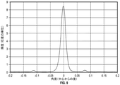
Apple Inc.(Cupertino,CA)のIPAD(第1世代)を用いて線を約65度の入射角でガラスラミネートの第1のガラス層上に投影した。線画像は2画素の幅であった。Radiant Vision Systems(Redmond,WA)から入手可能なPROMETRIC I8撮像測色計を用いて、反射輝度分布を1次反射像の中心ピークからの角度(例えば、図1Bの角度φ)の関数として決定し、これを図9に示している。1次反射像は約0.02度の半値全幅を有した。第1のゴースト画像が1次反射像から約0.08度に存在し、第2のゴースト画像が1次反射像から約−0.11度に存在した。 Apple Inc. Using the IPAD (1st generation) of (Cupertino, CA), lines were projected onto the first glass layer of the glass laminate at an incident angle of about 65 degrees. The line image was 2 pixels wide. Using a PROMETRIC I8 imaging colorimeter available from Radiant Vision Systems (Redmond, WA), the reflected luminance distribution was determined as a function of the angle from the central peak of the primary reflected image (eg, angle φ in FIG. 1B). , This is shown in FIG. The primary reflection image had a full width at half maximum of about 0.02 degrees. The first ghost image was present at about 0.08 degrees from the primary reflection image and the second ghost image was present at about −0.11 degrees from the primary reflection image.
実施例2
第1及び第2のガラス層が各々厚さ1mmであったことを除いて、実施例1について記載したように、実施例2を調製し、試験した。得られた反射輝度分布を、図10〜図11において、それぞれ、角度(例えば、図1Bの角度φ)及び場所(例えば、図1Aのx座標)の関数として示している。第1及び第2のゴースト画像は1次反射像と実質的に重なり合う。
Example 2
Example 2 was prepared and tested as described for Example 1, except that the first and second glass layers were each 1 mm thick. The obtained reflected luminance distribution is shown in FIGS. 10 to 11 as a function of an angle (for example, the angle φ in FIG. 1B) and a location (for example, the x-coordinate in FIG. 1A), respectively. The first and second ghost images substantially overlap with the primary reflection image.
比較例C1
第1の接着剤層が厚さ0.76mmのPVB層であったことを除いて、実施例1について記載したように、比較例C1を調製し、試験した。得られた反射輝度分布を、図12において、場所(図1Aのx座標)の関数として示している。第1及び第2のゴースト画像は十分に高い輝度を有し、画像忠実度の好ましくない喪失を生じさせるほど1次反射像から十分に変位した。
Comparative Example C1
Comparative Example C1 was prepared and tested as described for Example 1, except that the first adhesive layer was a 0.76 mm thick PVB layer. The obtained reflected luminance distribution is shown in FIG. 12 as a function of location (x coordinate in FIG. 1A). The first and second ghost images had sufficiently high brightness and were sufficiently displaced from the primary reflection image to cause an undesired loss of image fidelity.
実施例3〜4
第1の接着剤層が厚さ0.38mmのPVB層であったことを除いて、実施例1について記載したように、実施例3を調製した。第1のガラス層が厚さ3.2mmであったことを除いて、実施例1について記載したように、実施例4を調製した。より厚いガラス層を用いることは、ゴースト画像の位置に影響を及ぼすと予想されるが、線のうねりに及ぼす影響は無視できるほどになると予想される。
Examples 3-4
Example 3 was prepared as described for Example 1, except that the first adhesive layer was a PVB layer with a thickness of 0.38 mm. Example 4 was prepared as described for Example 1, except that the first glass layer was 3.2 mm thick. The use of a thicker glass layer is expected to affect the position of the ghost image, but the effect on line waviness is expected to be negligible.
約55度のガラスラミネートへの入射角で比較例C1、実施例3、及び実施例4のガラスラミネートの第1のガラス層を通して反射フィルム上に複数の平行線を投影し、PROMETRIC測色計を用いて反射像を分析した。図13A〜図13Cに、比較例C1、実施例3、及び実施例4のための反射像をそれぞれ示す。「Experimental investigation of collagen waviness and orientation in the arterial adventitia using confocal laser scanning microscopy」、Rezakhanihaら、Biomech Model Mechanobiol、2012年3月;11(3−4);461−73;doi:10.1007/s10237−011−0325−zにおいて大まかに説明される画像分析手順を用いて、各線に沿った十分な数の場所において、各線に対する中心線接線を決定し、中心線接線の配向の分布を決定した。図14に、得られた分布をプロットしている。分布ごとの半値全幅を決定し、比較例C1、実施例3、及び実施例4について、それぞれ、4.0度、1.9度、及び1.0度であることを見出した。 A plurality of parallel lines are projected onto the reflective film through the first glass layer of the glass laminate of Comparative Example C1, Example 3, and Example 4 at an angle of incidence on the glass laminate of about 55 degrees, and a PROMETRIC colorimeter is used. The reflected image was analyzed using. 13A to 13C show reflection images for Comparative Example C1, Example 3, and Example 4, respectively. "Experimental investment of collagen wavinences and orientation in the arterial adventitia using confocal laser scanning microscopy; The image analysis procedure roughly described in 011-0325-z was used to determine the centerline tangents for each line at a sufficient number of locations along each line and to determine the distribution of the orientation of the centerline tangents. FIG. 14 plots the obtained distribution. The full width at half maximum for each distribution was determined, and it was found that the widths of Comparative Example C1, Example 3, and Example 4 were 4.0 degrees, 1.9 degrees, and 1.0 degrees, respectively.
前述の参照文献、特許、又は特許出願はいずれも一貫した方法でそれらの全体を参照することにより本明細書に組み込まれる。組み込まれた参照文献の一部と本出願との間に不一致又は矛盾がある場合、前述の記載における情報が優先するものとする。 Any of the aforementioned references, patents, or patent applications are incorporated herein by reference in their entirety in a consistent manner. In the event of any discrepancy or inconsistency between some of the incorporated references and this application, the information in the above description shall prevail.
図中の要素の説明は、別段の指示がない限り、他の図中の対応する要素に等しく適用されるものと理解されたい。具体的な実施形態を本明細書において例示し記述したが、様々な代替及び/又は同等の実施により、図示及び記載した具体的な実施形態を、本開示の範囲を逸脱することなく置き換え可能であることが、当業者には理解されよう。本出願は、本明細書において説明した具体的な実施形態のあらゆる適合例又は変形例を包含することを意図する。したがって、本開示は、特許請求の範囲及びその同等物によってのみ限定されるものとする。 It should be understood that the description of an element in a figure applies equally to the corresponding elements in other figures, unless otherwise indicated. Although specific embodiments have been exemplified and described herein, various alternatives and / or equivalent embodiments can replace the illustrated and described specific embodiments without departing from the scope of the present disclosure. Those skilled in the art will understand that there is. This application is intended to include all conformances or variations of the specific embodiments described herein. Therefore, this disclosure is limited only by the scope of claims and their equivalents.
Claims (15)
互いに遠ざかる方に面した実質的に平行な最外主表面を有する第1及び第2のガラス層と、
対向する第1及び第2の主表面を有し、前記第1及び第2のガラス層の間に配設された反射フィルムであって、前記第1及び第2の主表面が前記それぞれの第1及び第2のガラス層に面しており、前記反射フィルムが、少なくとも15%の所定の入射角における所定の可視波長範囲内の第1の偏光状態に対する平均反射率、及び少なくとも30%の前記所定の入射角における前記所定の可視波長範囲内の直交する第2の偏光状態に対する平均透過率を有する、反射フィルムと、
前記第1のガラス層と前記反射フィルムとの間に配設され、それらを一体に接合する第1の接着剤層と、
前記第2のガラス層と前記反射フィルムとの間に配設され、それらを一体に接合する第2の接着剤層と、を含み、前記第2の接着剤層が前記第1の接着剤層よりも厚く、これにより、前記反射フィルムの前記第1の主表面が前記第1のガラス層の前記最外主表面から距離d1だけ分離されており、前記反射フィルムの前記第2の主表面が前記第2のガラス層の前記最外主表面から距離d2だけ分離されており、0.05≦d1/d2≦0.9である、ガラスラミネート。 It ’s a glass laminate,
A first and second glass layer having a substantially parallel outermost main surface facing away from each other,
A reflective film having first and second main surfaces facing each other and disposed between the first and second glass layers, wherein the first and second main surfaces are the respective first surfaces. Facing the first and second glass layers, the reflective film has an average reflectance for a first polarization state within a given visible wavelength range at a given angle of incidence of at least 15%, and at least 30% of said. A reflective film having an average transmittance for a second orthogonal polarized state within the predetermined visible wavelength range at a predetermined incident angle.
A first adhesive layer disposed between the first glass layer and the reflective film and integrally joining them,
A second adhesive layer disposed between the second glass layer and the reflective film and integrally joining them is included, and the second adhesive layer is the first adhesive layer. Thicker, thereby separating the first main surface of the reflective film from the outermost main surface of the first glass layer by a distance d1 and the second main surface of the reflective film. A glass laminate that is separated from the outermost main surface of the second glass layer by a distance d2 and has 0.05 ≦ d1 / d2 ≦ 0.9.
実質的に平行な最外主表面を有する第1及び第2のガラス層と、
複数の交互のポリマー干渉層を含み、前記最外主表面の間に非対称的に配設された反射フィルムと、を含み、これにより、前記ガラスラミネートの2m以内に位置付けられた光源が、前記ガラスラミネートの法線に対して30度〜85度の範囲内の角度θをなす第1の方向に沿って前記第1のガラス層の前記最外主表面上に線を投影して、前記線が、前記第1の方向及び前記法線によって画定される第1の平面と直交する第2の方向に沿って延び、0.05度以下の半値全幅を有する前記投影された線の中心線の周りの投影輝度分布を有するときに、前記投影された線の第1の部分が前記反射フィルムから反射し、前記投影された線の第2の部分が前記第1のガラス層の前記最外主表面から反射し、前記線の反射像が、前記反射された第1の部分によって画定される1次反射像部分、及び前記反射された第2の部分によって画定される第1のゴースト部分を含み、前記第1のゴースト部分が前記1次反射像部分と実質的に重なり合う、ガラスラミネート。 It ’s a glass laminate,
With the first and second glass layers having a substantially parallel outermost main surface,
It comprises a plurality of alternating polymer interference layers, including a reflective film asymmetrically disposed between the outermost main surfaces, whereby a light source located within 2 m of the glass laminate is the glass. A line is projected onto the outermost main surface of the first glass layer along a first direction forming an angle θ in the range of 30 degrees to 85 degrees with respect to the normal of the laminate, and the line is formed. Around the centerline of the projected line, extending along the first direction and the second direction orthogonal to the first plane defined by the normal and having a half-value full width of 0.05 degrees or less. When having the projected brightness distribution of, the first portion of the projected line is reflected from the reflective film and the second portion of the projected line is the outermost main surface of the first glass layer. Reflected from, the reflected image of the line includes a primary reflected image portion defined by the reflected first portion and a first ghost portion defined by the reflected second portion. A glass laminate in which the first ghost portion substantially overlaps with the primary reflection image portion.
実質的に平行な最外主表面を有する第1及び第2のガラス層と、
複数の交互のポリマー干渉層を含み、それぞれの第1及び第2の接着剤層を通じて前記第1及び第2のガラス層の間に配設され、接着された反射フィルムと、を含み、前記第1の接着剤層が前記第2の接着剤層の厚さの0.6倍以下の厚さを有し、これにより、光源が、前記ガラスラミネートの法線に対して30度〜85度の範囲内の角度θをなす第1の方向に沿って前記第1のガラス層の前記最外主表面上に複数の平行線を投影して、前記複数の平行線が、前記第1の方向及び前記法線によって画定される第1の平面と直交する第2の方向に沿って延び、前記第1の平面内にあって前記第1の方向と直交する第3の方向に沿って離間されているときに、各投影された線の第1の部分が前記反射フィルムから反射し、各線の反射像が、前記反射された第1の部分を含み、各反射像が、前記反射像の中心線を画定する輝度分布を有し、前記反射像の前記中心線と前記第2の方向との間の角度αの分布が3度未満の半値全幅を有する、ガラスラミネート。 It ’s a glass laminate,
With the first and second glass layers having a substantially parallel outermost main surface,
A reflective film comprising a plurality of alternating polymer interference layers, disposed and adhered between the first and second glass layers through the respective first and second adhesive layers, said the first. The adhesive layer of 1 has a thickness of 0.6 times or less the thickness of the second adhesive layer, whereby the light source is 30 to 85 degrees with respect to the normal of the glass laminate. A plurality of parallel lines are projected onto the outermost main surface of the first glass layer along a first direction forming an angle θ within the range, and the plurality of parallel lines are formed in the first direction and the first direction. Extending along a second direction orthogonal to the first plane defined by the normal and separated along a third direction within the first plane and orthogonal to the first direction. When is present, the first portion of each projected line is reflected from the reflective film, the reflected image of each line includes the reflected first portion, and each reflected image is the centerline of the reflected image. A glass laminate having a brightness distribution defining the above and having a half-value full width in which the distribution of the angle α between the centerline of the reflected image and the second direction is less than 3 degrees.
Applications Claiming Priority (3)
| Application Number | Priority Date | Filing Date | Title |
|---|---|---|---|
| US201862735567P | 2018-09-24 | 2018-09-24 | |
| US62/735,567 | 2018-09-24 | ||
| PCT/US2019/051733 WO2020068513A1 (en) | 2018-09-24 | 2019-09-18 | Glass laminate including reflective film |
Publications (2)
| Publication Number | Publication Date |
|---|---|
| JP2022500703A true JP2022500703A (en) | 2022-01-04 |
| JPWO2020068513A5 JPWO2020068513A5 (en) | 2022-09-28 |
Family
ID=68138785
Family Applications (1)
| Application Number | Title | Priority Date | Filing Date |
|---|---|---|---|
| JP2021516662A Pending JP2022500703A (en) | 2018-09-24 | 2019-09-18 | Glass laminate containing reflective film |
Country Status (5)
| Country | Link |
|---|---|
| US (1) | US20220050287A1 (en) |
| EP (1) | EP3856511A1 (en) |
| JP (1) | JP2022500703A (en) |
| CN (1) | CN112752646B (en) |
| WO (1) | WO2020068513A1 (en) |
Families Citing this family (3)
| Publication number | Priority date | Publication date | Assignee | Title |
|---|---|---|---|---|
| US20230358934A1 (en) * | 2020-10-01 | 2023-11-09 | 3M Innovative Properties Company | Integral Multilayer Optical Film |
| WO2022119996A1 (en) * | 2020-12-04 | 2022-06-09 | Solutia Inc. | Secondary image mitigation and solar control in hud systems |
| WO2022119994A1 (en) * | 2020-12-04 | 2022-06-09 | Solutia Inc. | Selective absorption for secondary image mitigation in hud systems |
Citations (3)
| Publication number | Priority date | Publication date | Assignee | Title |
|---|---|---|---|---|
| WO2017030654A1 (en) * | 2015-08-14 | 2017-02-23 | Gentex Corporation | Heads up display system |
| JP2018063076A (en) * | 2016-10-13 | 2018-04-19 | 株式会社ティラド | Heat exchanger |
| JP2018518713A (en) * | 2015-06-11 | 2018-07-12 | サン−ゴバン グラス フランスSaint−Gobain Glass France | Projection system for contact analog head-up display (HUD) |
Family Cites Families (13)
| Publication number | Priority date | Publication date | Assignee | Title |
|---|---|---|---|---|
| US5882774A (en) | 1993-12-21 | 1999-03-16 | Minnesota Mining And Manufacturing Company | Optical film |
| US6808658B2 (en) | 1998-01-13 | 2004-10-26 | 3M Innovative Properties Company | Method for making texture multilayer optical films |
| US6179948B1 (en) | 1998-01-13 | 2001-01-30 | 3M Innovative Properties Company | Optical film and process for manufacture thereof |
| US6952312B2 (en) | 2002-12-31 | 2005-10-04 | 3M Innovative Properties Company | Head-up display with polarized light source and wide-angle p-polarization reflective polarizer |
| JP2006215174A (en) * | 2005-02-02 | 2006-08-17 | Teijin Dupont Films Japan Ltd | Reflective polarizing film with hard coat |
| JP5856149B2 (en) | 2010-05-07 | 2016-02-09 | スリーエム イノベイティブ プロパティズ カンパニー | Feed block for producing multilayer polymer films |
| GB201307496D0 (en) * | 2013-04-25 | 2013-06-12 | Pilkington Group Ltd | Laminated glazing |
| JP6495897B2 (en) * | 2013-06-06 | 2019-04-03 | スリーエム イノベイティブ プロパティズ カンパニー | Anti-reflection OLED structure |
| US9606355B2 (en) * | 2014-09-29 | 2017-03-28 | Honeywell International Inc. | Apparatus and method for suppressing double images on a combiner head-up display |
| CN104267499B (en) * | 2014-10-14 | 2016-08-17 | 福耀玻璃工业集团股份有限公司 | A kind of head-up-display system |
| CN104267498B (en) * | 2014-10-14 | 2017-02-15 | 福耀玻璃工业集团股份有限公司 | Head up display system |
| CN108012535B (en) * | 2016-09-01 | 2022-05-10 | 法国圣戈班玻璃厂 | Composite glass pane for head-up display |
| CN106483663B (en) * | 2016-12-08 | 2019-01-11 | 福耀玻璃工业集团股份有限公司 | A kind of automobile head-up-display system |
-
2019
- 2019-09-18 WO PCT/US2019/051733 patent/WO2020068513A1/en unknown
- 2019-09-18 JP JP2021516662A patent/JP2022500703A/en active Pending
- 2019-09-18 US US17/274,594 patent/US20220050287A1/en active Pending
- 2019-09-18 CN CN201980062600.1A patent/CN112752646B/en active Active
- 2019-09-18 EP EP19783181.1A patent/EP3856511A1/en active Pending
Patent Citations (3)
| Publication number | Priority date | Publication date | Assignee | Title |
|---|---|---|---|---|
| JP2018518713A (en) * | 2015-06-11 | 2018-07-12 | サン−ゴバン グラス フランスSaint−Gobain Glass France | Projection system for contact analog head-up display (HUD) |
| WO2017030654A1 (en) * | 2015-08-14 | 2017-02-23 | Gentex Corporation | Heads up display system |
| JP2018063076A (en) * | 2016-10-13 | 2018-04-19 | 株式会社ティラド | Heat exchanger |
Also Published As
| Publication number | Publication date |
|---|---|
| US20220050287A1 (en) | 2022-02-17 |
| CN112752646A (en) | 2021-05-04 |
| CN112752646B (en) | 2023-04-14 |
| WO2020068513A1 (en) | 2020-04-02 |
| EP3856511A1 (en) | 2021-08-04 |
Similar Documents
| Publication | Publication Date | Title |
|---|---|---|
| US10746911B2 (en) | Transparent heat-shielding/heat-insulating member having transparent screen function | |
| US7123418B2 (en) | Head-up display with narrow band reflective polarizer | |
| EP2263111B1 (en) | Low layer count reflective polarizer with optimized gain | |
| JP2022500703A (en) | Glass laminate containing reflective film | |
| JP7466516B2 (en) | Optical system and optical film | |
| TW201518792A (en) | Multilayer reflective polarizer | |
| US20210294012A1 (en) | Optical system | |
| JP7326287B2 (en) | Optical Stacks and Polarizing Beamsplitters | |
| US20220146728A1 (en) | Optical film and glass laminate | |
| JP7462633B2 (en) | Optical Films and Polarizing Beam Splitters | |
| US11029455B2 (en) | Broadband visible reflector | |
| JP2007086142A (en) | Viewing angle control body | |
| US11740480B2 (en) | Polarization beam splitter and hot mirror for heads up display | |
| US20230393410A1 (en) | Display system for vehicle | |
| US20210325587A1 (en) | Multilayer reflective polarizer with crystalline low index layers | |
| JP2023020220A (en) | Combiner, head-up display and mobile body | |
| CN114762455A (en) | Reflective polarizer and display system |
Legal Events
| Date | Code | Title | Description |
|---|---|---|---|
| RD03 | Notification of appointment of power of attorney |
Free format text: JAPANESE INTERMEDIATE CODE: A7423 Effective date: 20220620 |
|
| A521 | Request for written amendment filed |
Free format text: JAPANESE INTERMEDIATE CODE: A523 Effective date: 20220916 |
|
| A621 | Written request for application examination |
Free format text: JAPANESE INTERMEDIATE CODE: A621 Effective date: 20220916 |
|
| A977 | Report on retrieval |
Free format text: JAPANESE INTERMEDIATE CODE: A971007 Effective date: 20230424 |
|
| A131 | Notification of reasons for refusal |
Free format text: JAPANESE INTERMEDIATE CODE: A131 Effective date: 20230509 |
|
| A521 | Request for written amendment filed |
Free format text: JAPANESE INTERMEDIATE CODE: A523 Effective date: 20230718 |
|
| A131 | Notification of reasons for refusal |
Free format text: JAPANESE INTERMEDIATE CODE: A131 Effective date: 20231031 |
|
| A521 | Request for written amendment filed |
Free format text: JAPANESE INTERMEDIATE CODE: A523 Effective date: 20240112 |
|
| A131 | Notification of reasons for refusal |
Free format text: JAPANESE INTERMEDIATE CODE: A131 Effective date: 20240402 |