JP5969924B2 - Container for liquid - Google Patents
Container for liquid Download PDFInfo
- Publication number
- JP5969924B2 JP5969924B2 JP2012555928A JP2012555928A JP5969924B2 JP 5969924 B2 JP5969924 B2 JP 5969924B2 JP 2012555928 A JP2012555928 A JP 2012555928A JP 2012555928 A JP2012555928 A JP 2012555928A JP 5969924 B2 JP5969924 B2 JP 5969924B2
- Authority
- JP
- Japan
- Prior art keywords
- cap
- container
- liquid
- spout
- liquid container
- Prior art date
- Legal status (The legal status is an assumption and is not a legal conclusion. Google has not performed a legal analysis and makes no representation as to the accuracy of the status listed.)
- Active
Links
- 239000007788 liquid Substances 0.000 title claims description 105
- 230000002093 peripheral effect Effects 0.000 claims description 51
- 239000003889 eye drop Substances 0.000 claims description 25
- 239000000463 material Substances 0.000 claims description 13
- 229940012356 eye drops Drugs 0.000 claims description 11
- -1 polypropylene Polymers 0.000 claims description 10
- 239000004743 Polypropylene Substances 0.000 claims description 7
- 229920001155 polypropylene Polymers 0.000 claims description 7
- 239000004793 Polystyrene Substances 0.000 claims description 6
- 229920002223 polystyrene Polymers 0.000 claims description 6
- 229920000122 acrylonitrile butadiene styrene Polymers 0.000 claims description 5
- 229920001893 acrylonitrile styrene Polymers 0.000 claims description 5
- SCUZVMOVTVSBLE-UHFFFAOYSA-N prop-2-enenitrile;styrene Chemical compound C=CC#N.C=CC1=CC=CC=C1 SCUZVMOVTVSBLE-UHFFFAOYSA-N 0.000 claims description 5
- 229920006026 co-polymeric resin Polymers 0.000 claims description 4
- 239000007769 metal material Substances 0.000 claims description 3
- 230000000694 effects Effects 0.000 description 10
- 229920003002 synthetic resin Polymers 0.000 description 9
- 239000000057 synthetic resin Substances 0.000 description 9
- 238000001125 extrusion Methods 0.000 description 6
- 239000000203 mixture Substances 0.000 description 5
- 229910052751 metal Inorganic materials 0.000 description 4
- 239000002184 metal Substances 0.000 description 4
- 238000000034 method Methods 0.000 description 4
- 229920005989 resin Polymers 0.000 description 4
- 239000011347 resin Substances 0.000 description 4
- 239000002537 cosmetic Substances 0.000 description 3
- 230000007423 decrease Effects 0.000 description 3
- 239000003814 drug Substances 0.000 description 3
- 229940079593 drug Drugs 0.000 description 3
- PCHJSUWPFVWCPO-UHFFFAOYSA-N gold Chemical compound [Au] PCHJSUWPFVWCPO-UHFFFAOYSA-N 0.000 description 3
- 239000010931 gold Substances 0.000 description 3
- 229910052737 gold Inorganic materials 0.000 description 3
- 239000004698 Polyethylene Substances 0.000 description 2
- 239000000654 additive Substances 0.000 description 2
- 229910052782 aluminium Inorganic materials 0.000 description 2
- XAGFODPZIPBFFR-UHFFFAOYSA-N aluminium Chemical compound [Al] XAGFODPZIPBFFR-UHFFFAOYSA-N 0.000 description 2
- 238000005034 decoration Methods 0.000 description 2
- 230000007613 environmental effect Effects 0.000 description 2
- 238000000465 moulding Methods 0.000 description 2
- 239000000546 pharmaceutical excipient Substances 0.000 description 2
- 229920000573 polyethylene Polymers 0.000 description 2
- 238000009751 slip forming Methods 0.000 description 2
- 239000004480 active ingredient Substances 0.000 description 1
- 230000000996 additive effect Effects 0.000 description 1
- 239000000956 alloy Substances 0.000 description 1
- 229910045601 alloy Inorganic materials 0.000 description 1
- 230000008901 benefit Effects 0.000 description 1
- 239000003795 chemical substances by application Substances 0.000 description 1
- 239000000306 component Substances 0.000 description 1
- 239000000882 contact lens solution Substances 0.000 description 1
- 238000005336 cracking Methods 0.000 description 1
- 238000005520 cutting process Methods 0.000 description 1
- 238000010586 diagram Methods 0.000 description 1
- 239000002552 dosage form Substances 0.000 description 1
- 238000007905 drug manufacturing Methods 0.000 description 1
- 239000000839 emulsion Substances 0.000 description 1
- 239000003205 fragrance Substances 0.000 description 1
- 230000008676 import Effects 0.000 description 1
- 239000004615 ingredient Substances 0.000 description 1
- 230000003993 interaction Effects 0.000 description 1
- 239000002932 luster Substances 0.000 description 1
- 230000007246 mechanism Effects 0.000 description 1
- 239000007923 nasal drop Substances 0.000 description 1
- 229940100662 nasal drops Drugs 0.000 description 1
- 239000007922 nasal spray Substances 0.000 description 1
- 239000000820 nonprescription drug Substances 0.000 description 1
- 239000004014 plasticizer Substances 0.000 description 1
- 229920013716 polyethylene resin Polymers 0.000 description 1
- 229920000139 polyethylene terephthalate Polymers 0.000 description 1
- 239000005020 polyethylene terephthalate Substances 0.000 description 1
- 229920005672 polyolefin resin Polymers 0.000 description 1
- 229920005990 polystyrene resin Polymers 0.000 description 1
- 238000002360 preparation method Methods 0.000 description 1
- 230000008569 process Effects 0.000 description 1
- 239000002994 raw material Substances 0.000 description 1
- 238000007493 shaping process Methods 0.000 description 1
- 239000008247 solid mixture Substances 0.000 description 1
- 239000000126 substance Substances 0.000 description 1
- 239000004094 surface-active agent Substances 0.000 description 1
- 239000005028 tinplate Substances 0.000 description 1
- 238000007740 vapor deposition Methods 0.000 description 1
Images


Classifications
-
- B—PERFORMING OPERATIONS; TRANSPORTING
- B65—CONVEYING; PACKING; STORING; HANDLING THIN OR FILAMENTARY MATERIAL
- B65D—CONTAINERS FOR STORAGE OR TRANSPORT OF ARTICLES OR MATERIALS, e.g. BAGS, BARRELS, BOTTLES, BOXES, CANS, CARTONS, CRATES, DRUMS, JARS, TANKS, HOPPERS, FORWARDING CONTAINERS; ACCESSORIES, CLOSURES, OR FITTINGS THEREFOR; PACKAGING ELEMENTS; PACKAGES
- B65D41/00—Caps, e.g. crown caps or crown seals, i.e. members having parts arranged for engagement with the external periphery of a neck or wall defining a pouring opening or discharge aperture; Protective cap-like covers for closure members, e.g. decorative covers of metal foil or paper
- B65D41/62—Secondary protective cap-like outer covers for closure members
-
- B—PERFORMING OPERATIONS; TRANSPORTING
- B65—CONVEYING; PACKING; STORING; HANDLING THIN OR FILAMENTARY MATERIAL
- B65D—CONTAINERS FOR STORAGE OR TRANSPORT OF ARTICLES OR MATERIALS, e.g. BAGS, BARRELS, BOTTLES, BOXES, CANS, CARTONS, CRATES, DRUMS, JARS, TANKS, HOPPERS, FORWARDING CONTAINERS; ACCESSORIES, CLOSURES, OR FITTINGS THEREFOR; PACKAGING ELEMENTS; PACKAGES
- B65D47/00—Closures with filling and discharging, or with discharging, devices
- B65D47/04—Closures with discharging devices other than pumps
- B65D47/06—Closures with discharging devices other than pumps with pouring spouts or tubes; with discharge nozzles or passages
- B65D47/12—Closures with discharging devices other than pumps with pouring spouts or tubes; with discharge nozzles or passages having removable closures
- B65D47/122—Threaded caps
- B65D47/123—Threaded caps with internal parts
-
- B—PERFORMING OPERATIONS; TRANSPORTING
- B65—CONVEYING; PACKING; STORING; HANDLING THIN OR FILAMENTARY MATERIAL
- B65D—CONTAINERS FOR STORAGE OR TRANSPORT OF ARTICLES OR MATERIALS, e.g. BAGS, BARRELS, BOTTLES, BOXES, CANS, CARTONS, CRATES, DRUMS, JARS, TANKS, HOPPERS, FORWARDING CONTAINERS; ACCESSORIES, CLOSURES, OR FITTINGS THEREFOR; PACKAGING ELEMENTS; PACKAGES
- B65D47/00—Closures with filling and discharging, or with discharging, devices
- B65D47/04—Closures with discharging devices other than pumps
- B65D47/06—Closures with discharging devices other than pumps with pouring spouts or tubes; with discharge nozzles or passages
- B65D47/18—Closures with discharging devices other than pumps with pouring spouts or tubes; with discharge nozzles or passages for discharging drops; Droppers
Landscapes
- Engineering & Computer Science (AREA)
- Mechanical Engineering (AREA)
- Closures For Containers (AREA)
- Medical Preparation Storing Or Oral Administration Devices (AREA)
Description
この発明は、閉栓開栓の操作性を改良した液体用容器に関する。
本願は、2011年2月1日に、日本に出願された特願2011−020150号の優先権を主張し、その内容をここに援用する。The present invention relates to a liquid container having improved operability for closing and opening.
This application claims the priority of Japanese Patent Application No. 2011-020150 for which it applied to Japan on February 1, 2011, and uses the content here.
一般的な液体用容器は、内容液を収容する収容部及び内容液を注出する注出口が形成された口頸部を有する容器本体と、口頸部に被冠して注出口を開閉するキャップとを備えている。そして、キャップは、口頸部に螺着させることで注出口を閉じることができるようになっている。
特に点眼薬用容器などの小容量の製品に使用される容器は、一般に容器本体が小さく、キャップの外径も小さく製作されている。また、意匠上の観点から、キャップの外管を細型(すなわち小径化)するとともに、外周面を鏡面仕上げにすることで、外観美麗かつスマートにしたものが広く愛好されている。A general liquid container has a container body having a container for storing a content liquid and a spout for pouring out the content liquid, and a container body that covers the mouth and neck to open and close the spout. With a cap. And a cap can close a spout by screwing to a mouth neck part.
In particular, containers used for small-capacity products such as eye drop containers are generally manufactured with a small container body and a small outer diameter of the cap. In addition, from the viewpoint of design, what is made beautiful and smart by making the outer tube of the cap thin (that is, by reducing the diameter) and mirror-finishing the outer peripheral surface is widely favored.
しかし、このようなキャップは、小径で鏡面仕上げであることから、使用者が手で握って閉栓する回動操作時に手の滑りを生じ易い。したがって、使用者が確実に締めた感覚を得ようとするあまり、適切な開閉栓位置を越えてキャップを締め過ぎる場合があり、使用時にキャップの開栓が困難となることがあった。また、上述のような鏡面仕上げを加えていなくても、キャップの形状・材質によっては強く締め過ぎる場合もあり、同様の問題が生じることがあった。 However, since such a cap has a small diameter and a mirror finish, it is easy for the user to slip during a turning operation in which the user holds and closes the cap. Therefore, there is a case where the cap is over-tightened beyond the appropriate opening / closing plug position so as to obtain a sense that the user is surely tightened, and it is sometimes difficult to open the cap at the time of use. Even if the mirror finish as described above is not applied, depending on the shape and material of the cap, it may be overtightened, and the same problem may occur.
また、液体用容器のキャップの材質は、ポリスチレン、ポリプロピレン等の合成樹脂材料であることが一般的であるが、容器に収容される内容液成分の種類や濃度、使用方法、使用環境等によって、キャップに亀裂が発生する等の問題が生ずることが分かった。具体的には、容器本体の口頸部に内容液が付着した状態でキャップを締めた場合に、キャップの締め付け強度が強すぎるとキャップ及び口頸部に強いストレスを与えることになり、この状態で更に周囲温度が40℃を超える等の環境条件が加わった場合に、内容液に含まれる化学成分と上記環境条件との相互作用によってキャップに亀裂が発生することが確認されている。 In addition, the material of the liquid container cap is generally a synthetic resin material such as polystyrene, polypropylene, etc., but depending on the type and concentration of the liquid component contained in the container, the method of use, the environment of use, etc. It was found that there were problems such as cracks in the cap. Specifically, when the cap is tightened with the content liquid adhering to the mouth and neck of the container body, if the cap is tightened too strongly, a strong stress is applied to the cap and mouth and neck. Further, it has been confirmed that when an environmental condition such as the ambient temperature exceeding 40 ° C. is applied, the cap cracks due to the interaction between the chemical component contained in the content liquid and the environmental condition.
この点、従来の液体用容器としては、容器本体の口頸部にキャップを螺着する際に、容器本体に対するキャップの回転位置を所定の位置に位置決めすることのできるものが提案されている(下記特許文献1参照)。 In this regard, as a conventional liquid container, a container capable of positioning the rotational position of the cap with respect to the container body at a predetermined position when the cap is screwed onto the mouth and neck of the container body has been proposed ( See Patent Document 1 below).
図12A〜図12Cは、かかる従来の容器の構成を示す図であり、これらの図に示す容器は、図12Bに示す容器本体1と図12Aに示すキャップ2とからなっている。
容器本体1は、その上部に口頸部3が形成されており、口頸部3には、その内部に収容された液体の押出口4が形成され、その外周面に雄螺子部5が形成されている。
また、容器本体1の口頸部3の下方には、図12Cに出すように係合片6、ストッパー7が形成されている。FIG. 12A to FIG. 12C are diagrams showing the configuration of such a conventional container, and the container shown in these figures includes a container body 1 shown in FIG. 12B and a
The container body 1 has a mouth / neck portion 3 formed on the upper portion thereof. The mouth / neck portion 3 is formed with a liquid extrusion port 4 accommodated therein, and a
Further, an
キャップ2は、その内部に螺着筒8を備えている。この螺着筒8の内面には雌螺子部9が形成され、さらに螺着筒8の下端にはストッパー杆10が形成されている。また、頂壁11の下面には栓体12が形成されている。
The
この容器は、使用者が容器本体1の口頸部3にキャップ2を螺着し、さらにキャップ2を回転させることによって栓体12が押出口4を閉栓する。この際、ストッパー杆10とストッパー7とは、キャップ2に施された印刷と容器本体1の表面の印刷とが整合する位置でキャップ2が停止するように、容器本体1に対してキャップ2の回転方向を位置決めしている。
In this container, the user screwes the
上記の図12A〜図12Cに示す容器では、ストッパー7を設けることによってキャップ2の回転方向の位置決めをしているが、上述したように印刷の位置を合わせるために行っている。そのため、キャップ2の螺合操作における、キャップ2の開栓の容易性や、キャップ2及び容器本体1の口頸部3に加わるストレスについては考慮されていない。
すなわち、この容器においては、使用者がキャップ2を口頸部3に被冠して回転させた際に、回転操作の途中で栓体12が押出口4に嵌合し押出口4を閉栓するが、この押出口4が閉栓された後さらに、ストッパー杆10がストッパー7に係合するまでキャップ2を回転させて容器本体1の印刷とキャップ2の印刷とを位置合わせするため、頂壁11及び嵌合した栓体12から押出口4近傍の壁部に伝わる回動トルクが増大する。すなわち、キャップ2の適切な閉栓位置を超えてキャップ2を回転させ、口頸部3の雄螺子部5とキャップ2の雌螺子部9との摩擦抵抗が増大して前記回動トルクの増大を助長してしまう。
したがって、上記従来の容器では、キャップ2を開栓困難な位置まで回動してしまうという問題が十分解決しなかった。In the containers shown in FIGS. 12A to 12C, the
That is, in this container, when the user puts the
Therefore, the above-described conventional container does not sufficiently solve the problem that the
また、キャップ2の回動の際、キャップ2の頂壁11及び栓体12及び雌螺子部9と容器本体1の口頸部3及びその雄螺子部5の周辺部分に大きなストレスが加わることになるため、この容器においても、内容液成分の種類、濃度や周囲環境の温度条件によってキャップ2に亀裂が入る問題が十分解決しなかった。
Further, when the
このように、従来の容器には、閉栓及び開栓時の操作性や、周囲環境によってキャップに亀裂を発生させ得る問題を満足に解決できるものは無かった。 As described above, none of the conventional containers can satisfactorily solve the problem that the cap can be cracked depending on the operability during closing and opening and the surrounding environment.
この発明の課題は、上記従来技術の問題に鑑み、容器本体の口頸部にキャップを螺着する液体用容器において、閉栓及び開栓時のキャップの操作を容易に行えるようにするとともに、容器の亀裂や損傷を防止し得る液体用容器及びこの液体用容器に液体を充填させた製品を提供することにある。 An object of the present invention is to provide a liquid container in which a cap is screwed onto a mouth / neck portion of a container body in view of the above-described problems in the container body, so that the cap can be easily operated during closing and opening. An object of the present invention is to provide a liquid container capable of preventing cracking and damage of the liquid and a product in which the liquid container is filled with liquid.
本発明は、上記課題を解決するため、以下の態様を有する。
(1)本発明の第1の態様は、先端に注出口が設けられるとともに外周面に雄螺子部が形成された口頸部を有する容器本体と、前記雄螺子部に螺合される雌螺子部が周壁部の内周面に形成されたキャップとを備えた液体用容器において、前記キャップには、前記注出口に嵌入してこの注出口を閉栓可能な突起部と、前記周壁部の前記内周面の下方に位置する被係止部とが設けられ、前記容器本体には、前記キャップを嵌着してこれを回動させたときに前記被係止部が当接して乗り越え可能な第1の係止部と、前記被係止部が前記第1の係止部を乗り越えた後、この被係止部が当接して前記キャップの締め方向の更なる回動を阻止する第2の係止部とが形成され、前記第2の係止部は、前記被係止部が当接した時に前記突起部が前記注出口を液密に閉栓する位置に形成されていることを特徴とする液体用容器である。In order to solve the above problems, the present invention has the following aspects.
(1) According to a first aspect of the present invention, a container body having a mouth and neck portion having a spout provided at the tip and having a male screw portion formed on the outer peripheral surface, and a female screw screwed into the male screw portion A liquid container having a cap formed on the inner peripheral surface of the peripheral wall portion, the cap having a projection that can be fitted into the spout and plugged into the spout, and the peripheral wall A locked portion located below the inner peripheral surface is provided, and when the cap is fitted and rotated on the container body, the locked portion abuts and can be overcome. After the first locking portion and the locked portion get over the first locking portion, the locked portion comes into contact to prevent further rotation in the tightening direction of the cap. And the second locking portion is configured such that when the locked portion abuts, the projection portion liquids the spout. It is a liquid container, characterized in that formed at a position plugging the.
(2)本発明の第2の態様は、前記(1)に記載の液体用容器において、
乗り越え可能な前記第1係止部の乗り越え開始位置と、第2係止部の係止位置との間の距離が、前記雌螺子部が前記雄螺子部の螺子山の係合始端から係合終端の当接可能な長さ以下に形成されていることを特徴とする液体用容器である。(2) According to a second aspect of the present invention, in the liquid container according to the above (1),
The distance between the over-starting position of the first locking portion that can be overcome and the locking position of the second locking portion is such that the female screw portion is engaged from the engagement start end of the screw thread of the male screw portion. The liquid container is characterized by being formed to have a length that is equal to or less than a length at which the terminal end can come into contact.
(3)本発明の第3の態様は、前記(1)又は(2)に記載の液体用容器において、
前記口頸部は、この口頸部の中心軸線を含む面で断面視したときに、前記雄螺子部上方の外周面の輪郭線が前記中心軸線に沿う直線状に形成され、
前記雌螺子部を形成する凸部の頂面は、前記外周面の輪郭線に平行に形成されていることを特徴とする液体用容器である。(3) According to a third aspect of the present invention, in the liquid container according to (1) or (2),
The mouth neck is formed in a straight line along the center axis when the outer periphery of the male screw part is cross-sectionally viewed in a plane including the center axis of the mouth neck.
The top surface of the convex portion forming the female screw portion is formed in parallel to the contour line of the outer peripheral surface.
(4)本発明の第4の態様は、前記(3)に記載の液体用容器において、
前記外周面の輪郭線における直線部の長さが、少なくとも雌螺子部を形成する凸部の頂面の長さ、及び/又は少なくとも隣接する雌螺子部の凸部の中心間の長さであることを特徴とする液体用容器である。(4) According to a fourth aspect of the present invention, in the liquid container according to (3),
The length of the straight line portion in the contour line of the outer peripheral surface is at least the length of the top surface of the convex portion forming the female screw portion and / or the length between the centers of the convex portions of the adjacent female screw portions. This is a liquid container.
(5)本発明の第5の態様は、前記(3)に記載の液体用容器において、
前記外周面の輪郭線における直線部の長さが、少なくとも隣接する雌螺子部の凸部の中心間の長さであることを特徴とする液体用容器である。(5) According to a fifth aspect of the present invention, in the liquid container according to (3),
The liquid container is characterized in that the length of the straight portion in the contour line of the outer peripheral surface is at least the length between the centers of the convex portions of the adjacent female screw portions.
(6)本発明の第6の態様は、前記(1)から(5)のいずれか一項に記載の液体用容器において、
前記雄螺子部の螺子山が、前記口頸部の周方向全周長さの2分の1以下の長さに形成され、
前記第2の係止部は、前記キャップの雌螺子部を前記雄螺子部の螺子山に螺合させて回動させたときに、前記螺子山の周方向の領域内で前記被係止部が当接する位置に形成されていることを特徴とする液体用容器である。(6) According to a sixth aspect of the present invention, in the liquid container according to any one of (1) to (5),
The screw thread of the male screw part is formed to have a length that is less than or equal to one half of the entire circumferential length of the mouth and neck part,
The second locking portion is configured to move the locked portion within a circumferential region of the screw thread when the female screw portion of the cap is screwed into the screw thread of the male screw portion and rotated. It is formed in the position which abuts, It is a container for liquids characterized by the above-mentioned.
(7)本発明の第7の態様は、前記(6)に記載の液体用容器において、
前記雄螺子部の螺子山が、前記口頸部の周方向全周長さの2分の1以下12分の1以上の長さに形成されていることを特徴とする液体用容器である。(7) According to a seventh aspect of the present invention, in the liquid container according to (6),
The thread container of the male screw part is a liquid container characterized in that it has a length that is less than or equal to one-half and less than or equal to one-twelfth of the entire circumferential length of the mouth-and-neck part.
(8)本発明の第8の態様は、前記(6)又は(7)に記載の液体用容器において、
前記雄螺子部の螺子山が、前記口頸部の周方向全周長さの2分の1以下8分の1以上の長さに形成され、かつ、前記中心軸線を間に挟んで互いに反対側となる位置に形成された多条螺子であることを特徴とする液体用容器である。(8) According to an eighth aspect of the present invention, in the liquid container according to the above (6) or (7),
The screw threads of the male screw part are formed to have a length that is less than or equal to one-half and less than or equal to one-eighth of the entire circumferential length of the mouth-and-neck part, and are opposite to each other with the central axis in between The liquid container is a multi-thread screw formed at a position on the side.
(9)本発明の第9の態様は、前記(8)に記載の液体用容器において、
前記多条螺子が2条螺子であることを特徴とする液体用容器。(9) According to a ninth aspect of the present invention, in the liquid container according to (8),
The liquid container, wherein the multi-thread screw is a double thread.
(10)本発明の第10の態様は、前記(1)から(9)のいずれか一項に記載の液体用容器において、前記キャップの開閉時の回動角度が30°以上180°以下であることを特徴とする液体用容器。 (10) According to a tenth aspect of the present invention, in the liquid container according to any one of (1) to (9), the rotation angle when the cap is opened and closed is 30 ° to 180 °. A container for liquid, characterized in that there is.
(11)本発明の第11の態様は、前記(1)から(10)のいずれか一項に記載の液体用容器において、前記キャップが、ポリスチレン、ポリプロピレン、アクリロニトリルスチレンコポリマー樹脂、又はABS樹脂の少なくともいずれか一を含む材料により形成されていることを特徴とする液体用容器である。 (11) An eleventh aspect of the present invention is the liquid container according to any one of (1) to (10), wherein the cap is made of polystyrene, polypropylene, acrylonitrile styrene copolymer resin, or ABS resin. A liquid container characterized by being formed of a material containing at least one of them.
(12)本発明の第13の態様は、前記(1)から(10)のいずれか一項に記載の液体用容器において、前記キャップは、ポリスチレン、ポリプロピレン、アクリロニトリルスチレンコポリマー樹脂、又はABS樹脂の少なくともいずれか一を含む材料により形成された内管と、金属材料で形成され、前記内管の外面に密着して被冠された外管と、を備えていることを特徴とする液体用容器である。 (12) According to a thirteenth aspect of the present invention, in the liquid container according to any one of (1) to (10), the cap is made of polystyrene, polypropylene, acrylonitrile styrene copolymer resin, or ABS resin. A liquid container comprising: an inner tube formed of a material containing at least one of the above; and an outer tube formed of a metal material and closely covered with an outer surface of the inner tube. It is.
(13)本発明の第13の態様は、前記(1)から(12)のいずれか一項に記載の液体用容器において、キャップの外径の最大部の寸法が20mmφ以下であることを特徴とする液体用容器である。 (13) A thirteenth aspect of the present invention is characterized in that, in the liquid container according to any one of (1) to (12), the maximum outer diameter of the cap is 20 mmφ or less. A container for liquid.
(14)本発明の第14の態様は、前記(1)から(13)のいずれか一項に記載の液体用容器において、容器本体の容量が35ml以下であることを特徴とする液体用容器である。 (14) A fourteenth aspect of the present invention is the liquid container according to any one of (1) to (13), wherein the container body has a capacity of 35 ml or less. It is.
(15)本発明の第15の態様は、前記(1)から(14)のいずれか一項に記載の液体用容器において、点眼薬の収容及び注出に用いられる容器であることを特徴とする液体用容器である。 (15) According to a fifteenth aspect of the present invention, in the liquid container according to any one of (1) to (14), the container is used for storing and dispensing eye drops. This is a liquid container.
前記(1)に係る本発明によれば、容器本体の閉栓にあたり、第2の係止部がキャップの前記被係止部に当接した時に前記突起部が前記注出口を閉栓する位置に形成されているので、前記被係止部が前記第2の係止部に当接するまで前記突起部が前記注出口を閉栓することによる回動操作トルクの増大を招来することがなく、閉栓操作を僅かな力で容易に行うことができ、この逆操作である開栓操作も僅かな力で容易に行うことができ、キャップの閉栓、開栓操作を容易に行うことができるという効果を奏する。 According to the present invention relating to (1), when the container body is plugged, the protruding portion is formed at a position where the spout is plugged when the second locking portion comes into contact with the locked portion of the cap. Therefore, the protrusion does not increase the rotation operation torque caused by closing the spout until the locked portion comes into contact with the second locking portion. The opening operation which is the reverse operation can be easily performed with a slight force, and the cap can be easily closed and opened.
また、前記被係止部が前記第2の係止部に当接するまで回動操作によるトルクの増大を招来することがないため、キャップと容器本体とに過大なストレスを与えることを防止し得て、これらの各部材に亀裂等損傷を生じさせることを防止することができるという効果を奏する。 In addition, since the torque does not increase due to the rotation operation until the locked portion comes into contact with the second locking portion, it is possible to prevent an excessive stress from being applied to the cap and the container body. Thus, it is possible to prevent the occurrence of damage such as cracks in these members.
また、キャップの締め付けや開閉操作時にキャップに与えるストレスが解消されることから、収容される液状組成物に含まれる各種成分の影響を受けず、経時的なキャップの亀裂、破損等の問題も解消できるという効果を奏する。 In addition, since the stress applied to the cap during cap tightening and opening / closing operations is eliminated, it is not affected by various components contained in the liquid composition contained, and problems such as cracks and breakage of the cap over time are also eliminated. There is an effect that can be done.
前記(2)に係る本発明によれば、乗り越え可能な第1係止部の乗り越え開始位置と、第2係止部の係止位置との間の距離が、雌螺子部が雄螺子部の螺子山の係合始端から係合終端の当接可能な長さ以下、すなわち、ねじ山のかかり長さ以内に納まるように形成されているので、前記(1)の効果をさらに高めることができる。 According to the present invention relating to (2) above, the distance between the over-starting position of the first locking part that can be overcome and the locking position of the second locking part is such that the female screw part is the male screw part. The effect of (1) can be further enhanced because the screw thread is formed so as to be within a length that can be abutted from the engagement starting end of the screw thread to the engagement terminal end, that is, within the threading length. .
前記(3)に係る本発明によれば、容器本体の口頸部上方の外周面の輪郭線を直線状に形成し、キャップの雌螺子部を形成する凸部の頂面を前記輪郭線に平行な直線状としたから、口頸部にキャップを被冠させる際にキャップの雌螺子部が口頸部上方の外周面に案内され、キャップが傾いた状態で螺着されることを防止し得て突起部による前記注出口の閉栓を液密状態に確実に行うことができるという効果を奏する。 According to the present invention according to (3) above, the outline of the outer peripheral surface above the mouth and neck of the container body is formed in a straight line, and the top surface of the convex part forming the female screw part of the cap is used as the outline. The parallel straight line prevents the cap's female threaded portion from being guided to the outer peripheral surface above the mouth / neck when the cap is put on the mouth / neck, preventing the cap from being screwed in an inclined state. Thus, there is an effect that the spout can be reliably closed in a liquid-tight state by the protrusion.
前記(4)及び(5)に係る本発明によれば、キャップの雌螺子部を形成する凸部の頂面の長さが、少なくとも隣接する雌螺子部の凸部の中心間の長さとすることにより、前記(3)の効果をさらに高めることができる。また、前記キャップ装着時のキャップ側、口頸部側の各螺子部の螺合がよりスムーズになるとともに、所定の位置までスムーズに回動させることができる。 According to the present invention according to the above (4) and (5), the length of the top surface of the convex portion forming the female screw portion of the cap is at least the length between the centers of the convex portions of the adjacent female screw portions. As a result, the effect (3) can be further enhanced. Further, the screwing of the screw parts on the cap side and the mouth / neck part side when the cap is mounted becomes smoother and can be smoothly rotated to a predetermined position.
前記(6)に係る本発明によれば、雄螺子部の螺子山が口頸部の周方向、全周長さの2分の1以下の長さに形成され、第2の係止部がキャップの雌螺子部をこの螺子山に係合させて回動させたときに螺子山の長さの範囲内で被係止部が当接する位置に形成されているので、キャップによる閉栓、開栓をひとひねり操作で行うことができ、閉栓、開栓操作をより簡単に行うことができるという効果を奏する。 According to the present invention according to (6) above, the thread of the male screw part is formed in the circumferential direction of the mouth-and-neck part and has a length equal to or less than one half of the entire peripheral length, and the second locking part is When the female screw part of the cap is engaged with this screw thread and rotated, it is formed at a position where the locked part comes into contact within the length of the screw thread. Can be performed by a single twisting operation, and the closure and opening operations can be performed more easily.
前記(7)に係る本発明によれば、雄螺子部の螺子山が口頸部の周方向、全周長さの2分の1以下12分の1以上の長さに形成され、第2の係止部がキャップの雌螺子部をこの螺子山に係合させて回動させたときに螺子山の長さの範囲内で被係止部が当接する位置に形成されているので、前記(6)の効果をさらに高めることができる。 According to the present invention according to (7) above, the screw thread of the male screw part is formed in the circumferential direction of the mouth and neck part, having a length that is less than or equal to 1/2 and less than or equal to 1/12 of the entire circumference. The engaging portion of the cap is formed at a position where the locked portion abuts within the range of the length of the screw thread when the female screw portion of the cap is engaged with the screw thread and rotated. The effect of (6) can be further enhanced.
前記(8)に係る本発明によれば、雄螺子部の螺子山が、前記口頸部の周方向全周長さの2分の1以下8分の1以上の長さに形成され、かつ、前記中心軸線を間に挟んで互いに反対側となる位置に形成された多条螺子とし、さらに、第2の係止部がキャップの雌螺子部をこの螺子山に係合させて回動させたときに螺子山の長さの範囲内で被係止部が当接する位置に形成されているので、前記(7)の効果をより確実にすることができる。 According to the present invention according to (8), the screw thread of the male screw part is formed to have a length that is less than or equal to one-half or more than one-eighth of the total circumferential length of the mouth-and-neck part, and And a multi-threaded screw formed at positions opposite to each other with the central axis in between, and a second locking portion for rotating the cap by engaging the female screw portion of the cap with the screw thread. In this case, the effect of the above (7) can be further ensured because the portion to be locked comes into contact with the thread within the length of the thread.
前記(9)に係る本発明によれば、前記(8)に係る本発明において、多条螺子を2条螺子とすることで、例えばサイズ制約が大きい小型の容器に適用した場合にも前記(8)に係る発明と同様の効果を奏することができ、製品等に用いる容器の選択肢を広げることができる。 According to the present invention according to (9) above, in the present invention according to (8) above, even when the multi-thread screw is a double thread, for example, when applied to a small container having a large size constraint, The effects similar to those of the invention according to 8) can be achieved, and the options for containers used for products and the like can be expanded.
前記(10)に係る本発明によれば、キャップの開閉時の回転角度を30°以上180°以下とすることで、開栓及び閉栓の操作をスムーズに行うことができるという効果を奏する。 According to the present invention according to (10), the opening and closing operations can be smoothly performed by setting the rotation angle when the cap is opened and closed to 30 ° to 180 °.
前記(11)に係る本発明によれば、液体用容器のキャップを成形性が良く、安価な合成樹脂材料により形成することができるという効果を奏する。なお、使用する樹脂については、これら樹脂の混合物であってもよく、また、キャップの成形にあたり、必要となる可塑剤等、その他成分が適宜含まれていてもよい。 According to the present invention according to the above (11), there is an effect that the cap of the liquid container can be formed of an inexpensive synthetic resin material with good moldability. In addition, about resin to be used, the mixture of these resin may be sufficient, and other components, such as a plasticizer required in the case of shaping | molding of a cap, may be contained suitably.
前記(12)に係る本発明によれば、液体用容器を合成樹脂製の内管と金属製の外管とにより構成したので、外管の表面を例えば鏡面仕上げとすることが可能となり、キャップの開閉が容易でありながら、外観美麗、スマート、更には高級感のある液体用容器を得ることができるという効果を奏する。 According to the present invention according to (12), since the liquid container is composed of the inner tube made of synthetic resin and the outer tube made of metal, the surface of the outer tube can be mirror-finished, for example, and the cap Although it is easy to open and close, it is possible to obtain a liquid container having a beautiful appearance, a smart appearance, and a high-class feeling.
前記(13)に係る本発明によれば、キャップをその最大径が20mmφ以下となるようにして外観がスマートとなる形状でありながら、キャップの閉栓操作を僅かな力で容易に行うことができ、この逆操作である開栓操作も僅かな力で容易に行うことができ、キャップの閉栓、開栓操作を容易に行うことができるという効果を奏する。 According to the present invention according to (13), the cap can be easily capped with a slight force while the cap has a smart appearance with a maximum diameter of 20 mmφ or less. The opening operation, which is the reverse operation, can be easily performed with a slight force, and the cap can be easily closed and opened.
前記(14)に係る本発明によれば、容器本体がコンパクトでありながら、キャップの閉栓操作を僅かな力で容易に行うことができ、この逆操作である開栓操作も僅かな力で容易に行うことができ、キャップの閉栓、開栓操作を容易に行うことができるという効果を奏する。 According to the present invention according to (14), the cap body can be easily closed with a slight force while the container body is compact, and the opening operation, which is the reverse operation, can be easily performed with a slight force. The cap can be easily closed and opened.
前記(15)に係る本発明によれば、前記被係止部が前記第2の係止部に当接するまで、回動操作によるトルクの増大を招来することがないため、キャップと容器本体とに過大なストレスを与えることを防止し得て、点眼薬の収容及び注出にして使用した場合にも、これらの各部材に亀裂等損傷を生じさせることを防止することができるという効果を奏する。 According to the present invention according to (15), since the torque does not increase due to the rotation operation until the locked portion comes into contact with the second locking portion, the cap and the container body In the case where the eye drops are contained and dispensed, it is possible to prevent the occurrence of damage such as cracks in these members. .
本発明は、複雑な構造を有さず、前記課題を解決できることから、特に点眼薬用容器など、容器容量が小さく、小径のキャップを有する容器に適用することが特に有用である。 Since the present invention does not have a complicated structure and can solve the above-described problems, it is particularly useful to apply to a container having a small container cap and a small diameter cap, such as an eye drop container.
以下、本発明の各実施形態に係る液体用容器及びこの液体用容器に液体を充填した製品について、点眼薬用容器に適用した例をもって図面を参照して説明する。
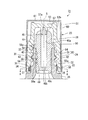
図1は、本発明の第1の実施形態に係る点眼薬用容器21の全体図であり、図2から図6は、本発明の第1の実施形態に係る点眼薬用容器21の要部を示す。Hereinafter, a liquid container according to each embodiment of the present invention and a product in which the liquid container is filled with a liquid will be described with reference to the drawings with an example applied to an eye drop container.
FIG. 1 is an overall view of an
図1,図2は、点眼薬用容器21の容器本体22にキャップ23を被冠して螺着、緊締し、容器本体22を閉栓した状態を示す図である。
1 and 2 are views showing a state in which a
容器本体22は、上端に口頸部24が形成された胴部25と、口頸部24に嵌着された中栓26とを備えている。
The
図1に示すように、胴部25には、その内部に点眼薬(目薬)、洗眼薬等の眼科用組成物、コンタクトレンズケア用剤、点鼻薬、外用薬、化粧品等の液状組成物が収容される。
なお、本実施形態の液体用容器は、容器本体22の口頸部24やキャップ23に付着しうる剤型であれば、例えば、ジェル状、乳液状の半固形状の組成物にも適用できる。
なお、液状組成物には、当業者の技術常識、公知の情報と照らし合わせ、通常、各種薬効成分や香料、界面活性剤等の添加剤成分が含まれる。具体的な成分としては、一般用医薬品製造(輸入)承認基準2000年版(薬事審査研究会監修)、医薬品添加物事典2005(日本医薬品添加剤協会編集)、医薬部外品原料規格2006(薬事日報社編)等に記載された各種、医薬、化粧品等における有効成分、添加物などが例示できる。As shown in FIG. 1, the
In addition, the liquid container of the present embodiment can be applied to a gel-like or emulsion semi-solid composition as long as it is a dosage form that can adhere to the mouth-
In addition, the liquid composition usually includes additive components such as various medicinal components, fragrances, and surfactants in light of technical common sense and public information of those skilled in the art. Specific ingredients include: Over-the-counter drug manufacturing (import) approval standards 2000 version (supervised by the Pharmaceutical Affairs Research Committee), Pharmaceutical Additives Encyclopedia 2005 (edited by the Japan Pharmaceutical Additives Association), Quasi-drug Raw Material Standard 2006 (Pharmaceutical Daily) Examples of active ingredients and additives in various types of medicines, cosmetics, etc.
図2に示すように、口頸部24は、筒状に形成された壁部であって、肉厚の下部壁27と、下部壁27から上方へ延出する上部壁28とからなっている。
As shown in FIG. 2, the mouth-and-
下部壁27及び上部壁28の内径は同一径とされており、下部壁27及び上部壁28の外径は、下部壁27よりも上部壁28の方が小径とされている。
上部壁28の外周面には、複数条(本実施形態では、螺子山30、30からなる2条)の雄螺子部31が連続的に形成されている。雄螺子部が連続的に形成されていることにより、キャップを閉栓する際に、被係止部が第2の係止部に当接するまで回動操作がよりスムーズになる。The inner diameters of the
On the outer peripheral surface of the
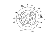
螺子山30、30は、図4、図5に示すように、口頸部24の周方向全周長さの略2分の1の長さに形成されているとともに、口頸部24の中央部又はこれより下方に形成されており、注出口40から螺子山30,30までの間が可及的に広く設定されている。さらに、これら螺子山30、30は、口頸部24の中心軸線Sを挟んで互いに反対側となる位置に形成されており、それぞれ同一高さにある始端30a、30aを起点として中心軸線Sの周囲を廻るように螺線状に巻回し、終端30b、30bに到るように形成されている。
As shown in FIGS. 4 and 5, the
図5、図6に示すように、乗り越え可能な第1係止部の乗り越え開始位置aと、第2係止部の係止位置bとの間の距離は、雌螺子部54が雄螺子部31の螺子山30の(係合)始端30aから(係合)終端30bの当接可能な長さ以下に形成されていることが好ましい。
As shown in FIGS. 5 and 6, the distance between the jump start position “a” of the first locking portion that can be crossed over and the locking position “b” of the second locking portion is such that the
口頸部24は、雄螺子部31を除く部分の内外径がその中心軸線S方向のどの位置でも同径とされている。口頸部24における雄螺子部31の上方部分は、上述したとおり可及的に広く設定されており、キャップ23を被冠させる際のガイド面32となっている。かくして、口頸部24は、図2に示すように、中心軸線Sを含む面で断面視したときに、雄螺子部31の上方の外周面の輪郭線は、中心軸線Sに沿って平行な直線状となっている。
The mouth-and-
また、この口頸部24の下部壁27には、第1の係止部33、第2の係止部34が形成されている。
A
これら第1の係止部33及び第2の係止部34は、下部壁27の外周面に形成されたものである。
図3に示すように、第1の係止部33は、キャップ23の被係止部35(キャップ23の詳細については後述する)を当接させてキャップ23の回動時に抵抗を付与する抵抗付与面33aと、被係止部35が乗り越えた後にキャップ23の不用意な開栓を防ぐ開栓止面33bとを有した膨出部である。また、第2の係止部34は、同被係止部35が当接したときに被係止部35のそれ以上の回動、すなわちキャップ23の締め方向の回動を阻止する突起である。The
As shown in FIG. 3, the
かくして、第1の係止部33は、これを平面視した場合に、抵抗付与面33aの端縁から周方向に漸次径方向外方へ膨出し、最大膨出部分を経た後、開栓止面33bにおいて漸次膨出高さを減少させてその端縁に到るように形成されている。
Thus, the
また、第2の係止部34は、第1の係止部33から前述した被係止部35が嵌り込む間隔をおいた位置に形成されており、第1の係止部33の膨出高より大とされた寸法で径方向外方に突出し、被係止部35が接触する受け面34aが中心軸線Sを含む仮想平面に沿って急峻に立ち上る面とされている。
Further, the
この第2の係止部34は、キャップ23を口頸部24の雄螺子部31に螺合して回動させたときに、口頸部24の周方向において、前記螺子山30の長さ方向の終端位置で被係止部35が接触する位置に形成されている。すなわち、第2の係止部34は、キャップ23の雌螺子部54を雄螺子部31の螺子山30に螺合させて回動させたときに、螺子山30の周方向の領域内で被係止部35が当接する位置に形成されている。
When the
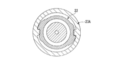
図2に示すように、中栓26は、断面円形の棒状部材であり、その中心軸線S上に注出口40が形成され、その外周面の上端寄り部分に環状の張出壁部41が形成されている。
そして、同外周面の張出壁部41の下方には、弾性変形可能な環状の係合突起42、43、44が形成されている。張出壁部41は、その周面が下端から上端へ向けて漸次径が小さくなる傾斜面とされている。As shown in FIG. 2, the
And the annular engaging
注出口40は、その上端から下端近傍部分までの同一径に形成された注出部40aと、この注出部40aに連続する下端近傍部分の絞り部40bと、この絞り部40bに連続して下方に開口する拡径部40cとからなっている。
The
中栓26の上端部外周面は、上端に向けて径が漸次小となる滑らかな湾曲凸面とされている。
The outer peripheral surface of the upper end portion of the
この中栓26は、その下端部が口頸部24の内部に圧入され、張出壁部41が口頸部24の上端面に当接し、係合突起42、43、44が弾性変形した状態で口頸部24の内面に圧接することにより、口頸部24内に固定されている。
The
上記の構成において、容器本体22、中栓26は、一般的にポリオレフィン樹脂、ポリスチレン樹脂、ポリエチレン樹脂等の合成樹脂材料により形成されている。特に容器本体22については、ポリエチレンテレフタレート、ポリプロピレン、ポリエチレン等、中栓については、ポリエチレン等が取り扱い易さの点で好ましい。
In the above configuration, the
また、本実施形態における点眼薬用容器21の容器本体22は、収容物により適宜選択されるが、よりコンパクトな容器構造が要求される小容量の容器に適用されることが好ましく、具体的には、50mL以下が好ましく、35mL以下がより好ましい。
In addition, the
キャップ23は、有底円筒形の部材であって、内管50と、この内管50に被冠して固定された外管51とから構成されたものである。
The
内管50は、ポリスチレン、ポリプロピレン、ABS樹脂、アクリロニトリルスチレンコポリマー(AS)樹脂の少なくともいずれか一の材料を含む合成樹脂材料により形成されている。
外管51は、アルミニウム、ブリキ等の合金等の金属材料により形成されている。この外管51は、いわゆる金冠等、キャップ23に金属、鏡面状の光沢を付加する装飾を目的とした部材である。なお、金冠は視覚的に金色のみに限定されない。The
The
内管50は、図2、図3に示すように有底円筒形に形成されたものであり、筒状の側壁部52と、この側壁部52の上端を塞ぐ天板壁53とからなるものである。
The
側壁部52は、その下部52aの内面に雌螺子部54が形成されており、下部52aの最下端が内面拡径部55とされている。
The
内面拡径部55には、中心軸線Sを間に挟んで対向する位置に被係止部35、35が内方に突出するように形成されている。
The inner diameter enlarged
側壁部52の下部52aは、その外周面が下端から上端へ向うに従って径が漸次小となるようにテーパ状に形成されている。
The
側壁部52の上部52bには、下方に窪んだ天板壁53が形成されている。天板壁53の下面中央部分には、下方へ突出して容器本体22の中栓26に形成された注出口40の上端部を閉栓及び開栓する突起部57が形成されている。
この突起部57は、その中央部に下方に向けて開口する穴57aが形成され、突起部57を形成する壁部を弾性変形し易くしている。A
The
前記雌螺子部54を形成する凹凸の各凸部58の頂面58aは、キャップ23を口頸部24に螺着した状態において、中心軸線Sを含む面で断面視したときに、中心軸線Sに沿う直線状で、容器本体22の口頸部24のガイド面32に平行に形成されている。
When the
外管51は、図2に示すように有底円筒状に形成されたものであって、筒状の側壁部60と天板壁61とからなっている。
As shown in FIG. 2, the
側壁部60は、下端から上端へ向うに従い、外径及び内径が漸次小となるようにテーパ状に形成されている。
The
この外管51は、例えばアウトサート成形法によって内管50と一体的に製作されるものであり、その外面にはいわゆる鏡面仕上げが施されている。
The
キャップ23は、その外径寸法が25mmφより大きい場合には使用者によって把持され易いのでその回動において困難を伴わない。しかし、外形寸法が25mmφ以下のキャップ23は、使用者に把持され難くその回動が容易でなくなるため、使用者が確実な締め感を得ようとして過度の力を加えてしまうことがある。そして、その結果、キャップ23は、開栓操作も行い難くなる。また、キャップ23の最大外径寸法が25mmφ以下の場合、キャップ23の外形が偏平形状であれば比較的把持しやすいものの、キャップ23の外形が円柱形状や截頭円錐形など断面が略円形に近づく程、使用者に把持され難くその回動が容易でなくなるため、上記同様の問題が発生しやすくなる。
したがって、キャップ23の最大外径寸法は、キャップ23の開閉が難しくなる25mmφ以下の場合に本実施形態が特に好適に適用され、20mmφ以下の場合により一層好適に適用される。さらに、その場合において、キャップ23の外形が円柱形状、截頭円錐形など、キャップ断面が略円形の場合に本実施形態が特に好適に適用される。When the outer diameter of the
Therefore, the maximum outer diameter dimension of the
上記の構成において、使用者がキャップ23を口頸部24に被冠し、雌螺子部54を雄螺子部31に螺着して回動させると、キャップ23の突起部57が中栓26における注出口40の上端部に進入し、この注出口40を液密に閉栓する。この際、中栓26の上端面とキャップ23の内管50の下面とは接触しておらず、これらの間に空間が形成された状態で突起部57と注出口40との間のみが当接することにより、注出口40が高い液密性をもって閉栓されている。
In the above configuration, when the user puts the
一方、突起部57が注出口40の上端部に進入すると、第1の係止部33は、キャップ23の被係止部35を当接させ、この第1の係止部33を乗り越えるまでの間、抵抗付与面33aにおいてキャップ23の回動に抵抗を付与し、使用者にキャップ23が閉まる直前であることを知覚させる。
そして、被係止部35が第1の係止部33の最大膨出部を乗り越えた後、第1の係止部33は、被係止部35と離間し、キャップ23の回動を一瞬軽くする。そして、突起部57が注出口40を液密に閉栓した時点で、口頸部24の第2の係止部34が被係止部35を当接させてそれ以上のキャップ23の回動を止める。この場合、被係止部35と第1の係止部33との係合が解かれてキャップ23の回転が軽くなった後に被係止部35と第2の係止部34とが強く当接するため、使用者は、キャップ23が確実に閉栓されたことを明確に知覚する。On the other hand, when the protruding
And after the to-
このように、第1の係止部33は、注出口40が突起部57によって閉栓される直前で被係止部35に当接される位置に形成されているとともに、被係止部35に乗り越えられた後、第2の係止部34に当接する直前に被係止部35との摩擦抵抗を無くすように形成されている。また、口頸部24の第2の係止部34は、キャップ23の被係止部35が当接した時に突起部57が注出口40を液密に閉栓する位置に形成されている。また、キャップ23の回動操作において雌螺子部54の一部が雄螺子部31の螺子山30の始端30aに係合して、前記雌螺子部54の一部が螺子山30の終端30b近傍まで回動したときに、被係止部35が第2の係止部34に当接する。
As described above, the
次に、上記の構成からなる点眼薬用容器21の使用方法について説明する。
まず、容器本体22を閉栓する場合には、使用者が図6に示すようにキャップ23を口頸部24及び中栓26に被冠し、図2に示すように雌螺子部54を雄螺子部31に螺着させる。Next, a method of using the
First, when the container
この場合、口頸部24の形状が、中心軸線Sを含む面で断面視したときに、雄螺子部31の上方のガイド面32の輪郭線が中心軸線Sに沿う(本実施形態においては略平行な)直線状に形成され、雌螺子部54の凹凸の各凸部58の頂面58aが前記輪郭線に平行な直線状に配置されているので、キャップ23がガイド面32に案内されてその軸線を口頸部24の軸線(中心軸線S)に合致させて口頸部24に被冠される。また、キャップ23が容器本体22に被冠された時に、注出口40とこの注出口40から離間した位置(口頸部24の下方)に形成された螺子山30,30とに支持されるため、口頸部24に対して傾くことがなく、後続の螺子の螺合及び閉栓を確実に行うことができる。
In this case, when the shape of the mouth-and-
キャップ23を口頸部24に螺着した後、このキャップ23を締め方向(時計回り方向)に回転させると、雌螺子部54が螺子山30の始端30aから終端30bに向けて案内され、その途中で被係止部35が第1の係止部33に当接する。
After the
ここで、キャップ23を回動操作する使用者は、前記当接によってキャップ23が閉栓直前位置にあること、すわなち、第2の係止部34が次に控えていることを知覚することができる。そして更にキャップ23を回動させると、被係止部35が第1の係止部33を乗り越え、乗り越えた時点でこの被係止部35が第2の係止部34に当接する。ここで、被係止部35は更なる回動が阻止され、従ってキャップ23の締めすぎが防止される。
Here, the user who rotates the
一方、第2の係止部34は、被係止部35が当接した時にキャップ23の突起部57が注出口40を液密に閉栓する位置に形成されているので、突起部57による閉栓が前記当接時に行われることになる。
On the other hand, the
したがって、この種の容器においては、キャップ23の回動操作において、突起部57が注出口40を閉栓した後、更に回動操作が可能であると、突起部57の閉栓による負荷によって締めすぎを招来し、キャップ23の開栓を困難にすることになる。一方、この点眼薬用容器21においては、被係止部35が第2の係止部34に当接した時点で液密な閉栓が完了するため、開栓が容易な位置にキャップ23を閉栓させることを容易に行うことができる。
Therefore, in this type of container, if the
上記のキャップ23による閉栓操作においては、被係止部35が第1の係止部33を乗り越えようとするまでは、雄螺子部31と雌螺子部54との間の摩擦抵抗が生じるだけであるから、その操作を僅かな力で行うことができる。特に、雄螺子部31が、中心軸線Sを間に挟んで反対側に位置する2条の螺子山30、30であるために、雌螺子部54との摩擦抵抗が極めて小さく、僅かな力で回動可能である。
In the closing operation by the
また、螺子山30が口頸部24の周方向全周長さの略2分の1の長さであり、キャップ23を螺子山30の始端30aから終端30b近傍まで回動したときに被係止部35が第2の係止部34に当接して閉栓が完了するので、閉栓時のキャップ23の回動角度が180°以下であり、キャップ23をいわゆるひとひねり(ワンクリック)することによって閉栓が可能であり、閉栓操作を容易に行うことができる。前記回転角度は、30°以上180°以下が好ましく、45°以上180°以下がより好ましく、90°以上180°以下がさらに好ましい。
Further, the
なお、上記のようにキャップ23により閉栓を行った場合には、被係止部35が第1の係止部33の開栓止面33bに係合するため、不用意に開栓されることはない。
When the
また、注出口40の開栓を行う場合には、使用者が、キャップ23を上記と逆方向に回動操作する。この場合、キャップ23の被係止部35が第1の係止部33を乗り越えれば、前述したように雄螺子部31と雌螺子部54との摩擦抵抗が僅かであるため、開栓操作を容易に行うことができる。
In addition, when opening the
また、この開栓操作も、ひとひねりで容易に行うことができる。 Moreover, this opening operation can be easily performed with a single twist.
また、上記構成の点眼薬用容器21によれば、キャップ23を、合成樹脂製の内管50と金属製の外管51とにより構成し、キャップ23の外径を例えば25mmφ以下の小径に形成するとともに、外管の表面を鏡面仕上げとした場合であっても、キャップ23の開閉操作を容易に行うことができる。よって、外観が美麗でスマートであり、高級感のある上に、開閉操作が容易な点眼薬用容器21を提供することができる。
Further, according to the
なお、上記実施形態において、第2の係止部34は、キャップ23を口頸部24の雄螺子部31に螺合して回動させたときに、口頸部24の周方向において、前記螺子山30の長さ方向の終端30bの位置で被係止部35が接触する位置に形成されているが、この構成のみに限られるものではなく、螺子山30の始端30aから終端30bの間に形成されたものであってもよい。すなわち、例えば、雄螺子部31が口頸部24の周方向全周長さの2分の1以上の長さに形成されていても、第2の係止部34が前記全周長さの2分の1から12分の1の長さ範囲内で被係止部35が当接する位置に形成されていればよい。
In the above embodiment, the
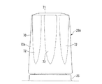
図7から図11は、本発明の第2の実施形態として示した点眼薬用容器21Aの要部を示す図である。これらの図において、前述した第1の実施形態の図1から図6と同一部分については同一符号を付し、その説明を省略する。
FIGS. 7 to 11 are views showing a main part of the
この第2の実施の形態が第1の実施の形態と異なる点は、キャップ23Aの構成である。すなわち、点眼薬用容器21Aのキャップ23Aは、図7から図9に示すように全体を合成樹脂により一体成形したものであり、図2に示すキャップ23のように外管を備えていない。
The difference between the second embodiment and the first embodiment is the configuration of the
キャップ23Aは、有底円筒状に形成されたものであり、円筒状の側壁部70と天板壁71とからなっている。
The
側壁部70は、下端から上端に向うに従い、外径及び内径が漸次小となるテーパ状に形成されたものであり、その内面側の形状は図2に示すキャップ23と同一である。
The
図10、図11に示すように側壁部70の外周面70aには、上端から下端近傍にかけて延びる係止凹条72、72・・が形成されている。係止凹条72、72・・は、キャップ23Aの周面をキャップ23Aの上端縁から下端近傍に至るまで切截したものであり、外周面70aに等間隔環状配置されており、使用者がキャップ23Aを回動操作する際に指に係止して滑りを防止するものである。
As shown in FIGS. 10 and 11, locking
この点眼薬用容器21Aにおいては、前述した第1の実施形成と同様の作用、効果が得られるほか、キャップ23Aを前述した一般的な合成樹脂により形成することができ、構成が簡単で安価に提供することができるという利点がある。
In this
なお、上記の実施の形態においては、雄螺子部31の螺子山30の長さを、口頸部24の周方向全周長さの略2分の1としたが、この長さはこれに限られるものではなく、通常、2分の1以下、好ましくは2分の1以下12分の1以上、より好ましくは2分の1以下8分の1以上、さらに好ましくは2分の1以下4分の1以上の範囲の長さであれば閉栓、開栓時のキャップのひとひねり操作が可能であり、かつキャップによる閉栓、開栓を確実に行うことができる。
In the above embodiment, the length of the
また、上記の実施の形態における雄螺子部30の螺子山は、2条螺子としたが、これに限られるものではなく、多条螺子であればよい。
なお、螺子が偶数の条数である場合、係止機構との兼ね合いで加工がよりし易くなり、また、容器の小型化という観点では、条数が少ない方が望ましい。Moreover, although the screw thread of the
When the number of threads is an even number, it is easier to process in consideration of the locking mechanism, and it is desirable that the number of threads is small from the viewpoint of downsizing the container.
また、上記の実施の形態における雄螺子部30は、連続的に形成されているとしたが、これに限られるものではない。
Moreover, although the
また、前記の各実施形態では、液体用容器を本発明の効果がより顕著に現れる点眼薬用容器21として適用した場合の例について説明したが、本発明の液体用容器は、もちろん、点眼薬用の容器以外の用途、たとえば点鼻薬やコンタクトレンズ洗浄液、化粧品、外皮用薬などの容器としても適用可能である。
In each of the above-described embodiments, an example in which the liquid container is applied as the
また、前記の第1の実施の形態では、本発明の液体用容器のキャップ23として、外管51、内管50の二重構造のキャップを適用した場合の例について説明したが、本発明は例えば、キャップを二重構造とせず、合成樹脂材料により形成されるキャップの外表面にアルミ蒸着等により、同様の装飾を施したものや、金属、鏡面状の光沢を付加する装飾を目的とせず、小径に形成されていたり、滑面を有していたりするなど、形状や樹脂材料によりキャップの開閉において操作性があまり良くないキャップを有する液体用容器にも適用可能である。
In the first embodiment, an example in which a cap having a double structure of the
本発明の液体用容器本体の口頸部にキャップを螺着する液体用容器において、閉栓及び開栓時のキャップの操作を容易に行えるようにするとともに、容器の締め過ぎによる容器の亀裂や損傷を防止し得る液体用容器及びこの液体用容器に液体を充填させることができるため、例えば、点眼薬用の容器として好適に用いることができる。 In the liquid container in which the cap is screwed onto the mouth and neck of the liquid container body of the present invention, the cap can be easily operated at the time of closing and opening, and the container is cracked or damaged due to overtightening of the container. Since the liquid container capable of preventing the liquid and the liquid container can be filled with the liquid, for example, it can be suitably used as a container for eye drops.
21点眼薬用容器(液体用容器)
22容器本体
23キャップ
24口頸部
30螺子山
31雄螺子部
32ガイド面(雄螺子部上方の外周面)
33第1の係止部
34第2の係止部
35被係止部
40注出口
54雌螺子部
57突起部
58a 凸部の頂面
S 中心軸線21 eye drops container (liquid container)
22
33
Claims (15)
前記キャップには、前記注出口に嵌入してこの注出口を閉栓可能な突起部と、前記周壁部の前記内周面の下方に位置する被係止部とが設けられ、
前記容器本体には、前記キャップを嵌着してこれを回動させたときに前記被係止部が当接して乗り越え可能な第1の係止部と、前記被係止部が前記第1の係止部を乗り越えた後、この被係止部が当接して前記キャップの締め方向の更なる回動を阻止する第2の係止部とが形成され、
前記第2の係止部は、前記被係止部が当接した時に前記突起部が前記注出口を液密に閉栓する位置に形成され、
前記口頸部は、この口頸部の中心軸線を含む面で断面視したときに、前記雄螺子部上方の外周面の輪郭線が前記中心軸線に沿う直線状に形成され、
前記雌螺子部を形成する凸部の頂面は、前記外周面の輪郭線に平行に形成され、
前記外周面の輪郭線における直線部の長さが、少なくとも隣接する雌螺子部の凸部の中心間の長さである
ことを特徴とする液体用容器。 A container body having a mouth and neck portion provided with a spout at the tip and having a male screw portion formed on the outer peripheral surface, and a female screw portion screwed into the male screw portion are formed on the inner peripheral surface of the peripheral wall portion. In a liquid container provided with a cap,
The cap is provided with a protrusion that can be fitted into the spout and can close the spout, and a locked portion that is located below the inner peripheral surface of the peripheral wall,
The container body has a first locking portion that can be moved over by the locked portion when the cap is fitted and rotated, and the locked portion is the first locking portion. A second locking portion is formed, which is engaged with the locked portion to prevent further rotation in the tightening direction of the cap,
The second locking portion is formed at a position where the projection portion liquid-tightly closes the spout when the locked portion abuts .
The mouth neck is formed in a straight line along the center axis when the outer periphery of the male screw part is cross-sectionally viewed in a plane including the center axis of the mouth neck.
The top surface of the convex portion forming the female screw portion is formed in parallel to the contour line of the outer peripheral surface,
The liquid container, wherein the length of the straight line portion in the contour line of the outer peripheral surface is at least the length between the centers of the convex portions of the adjacent female screw portions .
前記キャップには、前記注出口に嵌入してこの注出口を閉栓可能な突起部と、前記周壁部の前記内周面の下方に位置する被係止部とが設けられ、The cap is provided with a protrusion that can be fitted into the spout and can close the spout, and a locked portion that is located below the inner peripheral surface of the peripheral wall,
前記容器本体には、前記キャップを嵌着してこれを回動させたときに前記被係止部が当接して乗り越え可能な第1の係止部と、前記被係止部が前記第1の係止部を乗り越えた後、この被係止部が当接して前記キャップの締め方向の更なる回動を阻止する第2の係止部とが形成され、The container body has a first locking portion that can be moved over by the locked portion when the cap is fitted and rotated, and the locked portion is the first locking portion. A second locking portion is formed, which is engaged with the locked portion to prevent further rotation in the tightening direction of the cap,
前記第2の係止部は、前記被係止部が当接した時に前記突起部が前記注出口を液密に閉栓する位置に形成され、The second locking portion is formed at a position where the projection portion liquid-tightly closes the spout when the locked portion abuts.
前記雄螺子部の螺子山が、前記口頸部の周方向全周長さの2分の1以下の長さに形成され、かつ、前記中心軸線を間に挟んで互いに反対側となる位置に形成された多条螺子であり、The screw thread of the male screw part is formed to have a length less than or equal to one half of the entire circumferential length of the mouth-and-neck part, and at positions opposite to each other with the central axis line in between. A multi-thread formed,
前記第2の係止部は、前記キャップの雌螺子部が前記雄螺子部の螺子山の前記始端から前記終端近傍まで案内される範囲で前記被係止部が当接する位置に形成され、The second locking portion is formed at a position where the locked portion abuts in a range in which the female screw portion of the cap is guided from the start end of the screw thread of the male screw portion to the vicinity of the end.
前記キャップの外径の最大部の寸法が20mmφ以下であり、The dimension of the maximum part of the outer diameter of the cap is 20 mmφ or less,
点眼薬の収容及び注出に用いられる容器であるA container used to store and dispense eye drops
ことを特徴とする液体用容器。A container for liquid.
前記キャップには、天板壁と、前記天板壁から下方へ突出し前記注出口に嵌入してこの注出口を閉栓可能な突起部と、前記周壁部の前記内周面において前記雌螺子部の下方に形成された被係止部とが設けられ、The cap has a top plate wall, a projection that projects downward from the top plate wall and fits into the spout, and can plug the spout, and on the inner peripheral surface of the peripheral wall, below the female screw. A formed locked portion is provided,
前記容器本体には、前記キャップを嵌着してこれを回動させたときに前記被係止部が当接して乗り越え可能な第1の係止部と、前記被係止部が前記第1の係止部を乗り越えた後、この被係止部が当接して前記キャップの締め方向の更なる回動を阻止する第2の係止部とが形成され、The container body has a first locking portion that can be moved over by the locked portion when the cap is fitted and rotated, and the locked portion is the first locking portion. A second locking portion is formed, which is engaged with the locked portion to prevent further rotation in the tightening direction of the cap,
前記第2の係止部は、前記被係止部が当接した時に、前記突起部が前記注出口を液密に閉栓するとともに前記中栓の上端面と前記天板壁の下面とが接触しない位置に形成され、In the second locking portion, when the locked portion abuts, the projection portion liquid-tightly closes the spout and the upper end surface of the inner plug does not contact the lower surface of the top plate wall. Formed in position,
点眼薬の収容及び注出に用いられる容器であるA container used to store and dispense eye drops
ことを特徴とする液体用容器。A container for liquid.
前記キャップには、前記注出口に嵌入してこの注出口を閉栓可能な突起部と、前記周壁部の前記内周面において前記雌螺子部の下方に形成された被係止部とが設けられ、The cap is provided with a protrusion that can be fitted into the spout and can close the spout, and a locked portion formed below the female screw portion on the inner peripheral surface of the peripheral wall portion. ,
前記容器本体には、前記キャップを嵌着してこれを回動させたときに前記被係止部が当接して乗り越え可能な第1の係止部と、前記被係止部が前記第1の係止部を乗り越えた後、この被係止部が当接して前記キャップの締め方向の更なる回動を阻止する第2の係止部とが形成され、The container body has a first locking portion that can be moved over by the locked portion when the cap is fitted and rotated, and the locked portion is the first locking portion. A second locking portion is formed, which is engaged with the locked portion to prevent further rotation in the tightening direction of the cap,
前記第2の係止部は、前記被係止部が当接した時に、前記突起部が前記注出口を液密に閉栓するとともに前記キャップの下端と前記胴部との間に上下方向に隙間が形成される位置に形成され、The second locking portion is configured such that, when the locked portion comes into contact, the projection portion liquid-tightly closes the spout, and a vertical gap is provided between the lower end of the cap and the trunk portion. Formed at the position where
点眼薬の収容及び注出に用いられる容器であるA container used to store and dispense eye drops
ことを特徴とする液体用容器。A container for liquid.
前記口頸部は、この口頸部の中心軸線を含む面で断面視したときに、前記雄螺子部上方の外周面の輪郭線が前記中心軸線に沿う直線状に形成され、
前記雌螺子部を形成する凸部の頂面は、前記外周面の輪郭線に平行に形成されていることを特徴とする液体用容器。 In the container for liquids as described in any one of Claim 2 to 4 ,
The mouth neck is formed in a straight line along the center axis when the outer periphery of the male screw part is cross-sectionally viewed in a plane including the center axis of the mouth neck.
The top surface of the convex part which forms the said female thread part is formed in parallel with the outline of the said outer peripheral surface, The container for liquids characterized by the above-mentioned.
前記外周面の輪郭線における直線部の長さが、少なくとも前記雌螺子部を形成する凸部の頂面の長さであるか、及び/又は少なくとも隣接する雌螺子部の凸部の中心間の長さであることを特徴とする液体用容器。 The liquid container according to claim 1 or 5 ,
The length of the straight line portion in the contour line of the outer peripheral surface is at least the length of the top surface of the convex portion forming the female screw portion, and / or at least between the centers of the convex portions of adjacent female screw portions. A liquid container characterized by its length.
前記外周面の輪郭線における直線部の長さが、少なくとも隣接する雌螺子部の凸部の中心間の長さであることを特徴とする液体用容器。 The liquid container according to claim 5 or 6 ,
The liquid container, wherein the length of the straight line portion in the contour line of the outer peripheral surface is at least the length between the centers of the convex portions of the adjacent female screw portions.
乗り越え可能な前記第1の係止部の乗り越え開始位置は、前記雌螺子部が前記雄螺子部の螺子山の始端から終端に向けて案内される途中で前記被係止部が前記第1の係止部に当接する位置に形成され、第2の係止部の係止位置は、前記被係止部が前記第1の係止部を乗り越えた後で前記雌螺子部が前記雄螺子部の前記螺子山の前記始端から前記終端近傍まで案内されたときに前記被係止部が第2の係止部に当接する位置に形成されていることを特徴とする液体用容器。 The liquid container according to any one of claims 1 to 7 ,
Overcoming the start position of the first engaging portion capable of overcoming, the female screw portion is said to be locked portion from the beginning of the thread on the way guided towards the end of the male screw portion is the first The locking position of the second locking portion is formed at a position that contacts the locking portion. The locking position of the second locking portion is such that the female screw portion is moved to the male screw portion after the locked portion has climbed over the first locking portion. A liquid container , wherein the locked portion is formed at a position where the locked portion comes into contact with the second locking portion when guided from the start end to the vicinity of the end of the screw thread .
前記雄螺子部の螺子山が、前記口頸部の周方向全周長さの2分の1以下の長さに形成され、
前記第2の係止部は、前記キャップの雌螺子部が前記雄螺子部の螺子山の前記始端から前記終端近傍まで案内される範囲で前記被係止部が当接する位置に形成されていることを特徴とする液体用容器。 The liquid container according to claim 1 , 3 or 4 ,
The screw thread of the male screw part is formed to have a length that is less than or equal to one half of the entire circumferential length of the mouth and neck part,
Said second locking portion, a female threaded portion of the cap said the engaged portion from the beginning of the thread to the extent guided to the near the end of the male screw portion is formed at a position abutting A container for liquid.
前記キャップが、ポリスチレン、ポリプロピレン、アクリロニトリルスチレンコポリマー樹脂、又はABS樹脂の少なくともいずれか一を含む材料により形成されていることを特徴とする液体用容器。 In the liquid container according to any one of claims 1 to 10,
The liquid container, wherein the cap is made of a material containing at least one of polystyrene, polypropylene, acrylonitrile styrene copolymer resin, and ABS resin.
前記キャップは、ポリスチレン、ポリプロピレン、アクリロニトリルスチレンコポリマー樹脂、又はABS樹脂の少なくともいずれか一を含む材料により形成された内管と、
金属材料で形成され、前記内管の外面に密着して被冠された外管と、を備えていることを特徴とする液体用容器。 The liquid container according to any one of claims 1 to 11 ,
The cap includes an inner tube formed of a material containing at least one of polystyrene, polypropylene, acrylonitrile styrene copolymer resin, or ABS resin;
A liquid container, comprising: an outer tube formed of a metal material and crowned in close contact with the outer surface of the inner tube.
容器本体の容量が35ml以下であることを特徴とする液体用容器。 The liquid container according to any one of claims 1 to 12 ,
A container for liquid, wherein the volume of the container body is 35 ml or less.
キャップの外径の最大部の寸法が20mmφ以下であることを特徴とする液体用容器。 The liquid container according to claim 1 , 3 or 4 ,
A liquid container characterized in that the maximum dimension of the outer diameter of the cap is 20 mmφ or less.
点眼薬の収容及び注出に用いられる容器であることを特徴とする液体用容器。 The liquid container according to claim 1 ,
A container for liquid, which is a container used for storing and dispensing eye drops.
Applications Claiming Priority (3)
| Application Number | Priority Date | Filing Date | Title |
|---|---|---|---|
| JP2011020150 | 2011-02-01 | ||
| JP2011020150 | 2011-02-01 | ||
| PCT/JP2012/052266 WO2012105605A1 (en) | 2011-02-01 | 2012-02-01 | Liquid container |
Publications (2)
| Publication Number | Publication Date |
|---|---|
| JPWO2012105605A1 JPWO2012105605A1 (en) | 2014-07-03 |
| JP5969924B2 true JP5969924B2 (en) | 2016-08-17 |
Family
ID=46602812
Family Applications (1)
| Application Number | Title | Priority Date | Filing Date |
|---|---|---|---|
| JP2012555928A Active JP5969924B2 (en) | 2011-02-01 | 2012-02-01 | Container for liquid |
Country Status (4)
| Country | Link |
|---|---|
| JP (1) | JP5969924B2 (en) |
| CN (1) | CN103347791B (en) |
| TW (1) | TWI570033B (en) |
| WO (1) | WO2012105605A1 (en) |
Cited By (1)
| Publication number | Priority date | Publication date | Assignee | Title |
|---|---|---|---|---|
| JP2021024590A (en) * | 2019-07-31 | 2021-02-22 | 日本クロージャー株式会社 | Packing material for dripping and discharging vessel content liquid |
Families Citing this family (6)
| Publication number | Priority date | Publication date | Assignee | Title |
|---|---|---|---|---|
| JP6660244B2 (en) * | 2015-09-15 | 2020-03-11 | 天龍化学工業株式会社 | Screw lid type container |
| IT201700117868A1 (en) * | 2017-10-18 | 2019-04-18 | Matic Plast Milano Srl | METHOD AND EQUIPMENT FOR THE MANUFACTURE OF A CLOSING PLUG, PARTICULARLY FOR THE PACKAGING OF PRODUCTS OF THE PERFUMERY AND COSMETICS SECTOR. |
| KR101969461B1 (en) * | 2017-11-30 | 2019-04-16 | (주)연우 | Container for Discharging liquid type contents |
| JP7179760B2 (en) * | 2017-12-06 | 2022-11-29 | 住友ゴム工業株式会社 | tip cap |
| KR101955208B1 (en) * | 2017-12-18 | 2019-03-07 | 엘앤피코스메틱 (주) | Ampoule for storing cosmetic liquid |
| JP7435081B2 (en) * | 2020-03-16 | 2024-02-21 | 住友ベークライト株式会社 | Storage containers for physics and chemistry |
Citations (7)
| Publication number | Priority date | Publication date | Assignee | Title |
|---|---|---|---|---|
| US3339773A (en) * | 1966-05-11 | 1967-09-05 | Stull Engraving Company | Screw closure |
| US4093096A (en) * | 1977-05-19 | 1978-06-06 | Societe Anonyme Dite: Arts Et Techniques Nouvelles | Removable stopper for a screw-neck bottle |
| GB2126565A (en) * | 1982-08-11 | 1984-03-28 | U G Closures And Plastics Limi | Screw-capped container |
| JPH1159707A (en) * | 1997-08-12 | 1999-03-02 | Yoshino Kogyosho Co Ltd | Extruding container |
| JP2000016445A (en) * | 1998-06-30 | 2000-01-18 | Taisei Kako Kk | Container with cap |
| JP2003034343A (en) * | 2001-07-26 | 2003-02-04 | Takeuchi Press Ind Co Ltd | Sealing structure of mouth part and shoulder part of tubular container with cap |
| FR2946028A1 (en) * | 2009-05-26 | 2010-12-03 | Oreal | Nozzle element i.e. sealing cap, for use on collar of container, has helicoid thread covered radially in direction starting from wall and having profile distinct from profile of base helical thread to radially contact on closing element |
Family Cites Families (2)
| Publication number | Priority date | Publication date | Assignee | Title |
|---|---|---|---|---|
| JP3971329B2 (en) * | 2002-10-23 | 2007-09-05 | ロート製薬株式会社 | Nozzle structure of liquid container |
| CN101613005B (en) * | 2009-07-06 | 2011-08-17 | 章泽宏 | Bottle structure |
-
2012
- 2012-02-01 TW TW101103250A patent/TWI570033B/en active
- 2012-02-01 JP JP2012555928A patent/JP5969924B2/en active Active
- 2012-02-01 CN CN201280006920.3A patent/CN103347791B/en active Active
- 2012-02-01 WO PCT/JP2012/052266 patent/WO2012105605A1/en active Application Filing
Patent Citations (7)
| Publication number | Priority date | Publication date | Assignee | Title |
|---|---|---|---|---|
| US3339773A (en) * | 1966-05-11 | 1967-09-05 | Stull Engraving Company | Screw closure |
| US4093096A (en) * | 1977-05-19 | 1978-06-06 | Societe Anonyme Dite: Arts Et Techniques Nouvelles | Removable stopper for a screw-neck bottle |
| GB2126565A (en) * | 1982-08-11 | 1984-03-28 | U G Closures And Plastics Limi | Screw-capped container |
| JPH1159707A (en) * | 1997-08-12 | 1999-03-02 | Yoshino Kogyosho Co Ltd | Extruding container |
| JP2000016445A (en) * | 1998-06-30 | 2000-01-18 | Taisei Kako Kk | Container with cap |
| JP2003034343A (en) * | 2001-07-26 | 2003-02-04 | Takeuchi Press Ind Co Ltd | Sealing structure of mouth part and shoulder part of tubular container with cap |
| FR2946028A1 (en) * | 2009-05-26 | 2010-12-03 | Oreal | Nozzle element i.e. sealing cap, for use on collar of container, has helicoid thread covered radially in direction starting from wall and having profile distinct from profile of base helical thread to radially contact on closing element |
Cited By (2)
| Publication number | Priority date | Publication date | Assignee | Title |
|---|---|---|---|---|
| JP2021024590A (en) * | 2019-07-31 | 2021-02-22 | 日本クロージャー株式会社 | Packing material for dripping and discharging vessel content liquid |
| JP7351666B2 (en) | 2019-07-31 | 2023-09-27 | 日本クロージャー株式会社 | Packaging material that drips out the liquid contained in the container |
Also Published As
| Publication number | Publication date |
|---|---|
| JPWO2012105605A1 (en) | 2014-07-03 |
| TWI570033B (en) | 2017-02-11 |
| CN103347791B (en) | 2015-06-03 |
| TW201302558A (en) | 2013-01-16 |
| CN103347791A (en) | 2013-10-09 |
| WO2012105605A1 (en) | 2012-08-09 |
Similar Documents
| Publication | Publication Date | Title |
|---|---|---|
| JP5969924B2 (en) | Container for liquid | |
| US5941404A (en) | Tabbed threaded container cap | |
| US5295981A (en) | Eyedrop applicator attachment | |
| US7918336B2 (en) | Closure device with corrugated ring plunger part | |
| US7614514B2 (en) | Tamper evident tube closure with twist-away centering | |
| US20060043052A1 (en) | Bottle closure | |
| JP7188809B2 (en) | Screw cap rotation aid | |
| CN205499561U (en) | Liquid container | |
| JP6243354B2 (en) | Refill container pouring structure | |
| US20040140329A1 (en) | Ovaloid bottle with overcap | |
| US10336516B2 (en) | Childproof safety cap and associated container for liquid or pasty substances | |
| JP7394922B2 (en) | liquid container | |
| JP6877983B2 (en) | cap | |
| JP5909951B2 (en) | Composite cap | |
| JP6807206B2 (en) | Composite cap | |
| CN111319867B (en) | Packaging container | |
| US11399615B2 (en) | Cosmetic bottle with switch | |
| CN219030457U (en) | Cosmetic packaging bottle | |
| JPS5912543B2 (en) | twist off plastic container | |
| CN214525549U (en) | Bottle mouth structure | |
| JP3466992B2 (en) | cap | |
| JP5950730B2 (en) | Container cap | |
| JP2023084359A (en) | Metal tube container opening cap and tube product | |
| KR200382653Y1 (en) | dual compartment's container | |
| JP2022061403A (en) | Spout structure |
Legal Events
| Date | Code | Title | Description |
|---|---|---|---|
| A621 | Written request for application examination |
Free format text: JAPANESE INTERMEDIATE CODE: A621 Effective date: 20141217 |
|
| A131 | Notification of reasons for refusal |
Free format text: JAPANESE INTERMEDIATE CODE: A131 Effective date: 20151104 |
|
| A521 | Request for written amendment filed |
Free format text: JAPANESE INTERMEDIATE CODE: A523 Effective date: 20151228 |
|
| TRDD | Decision of grant or rejection written | ||
| A01 | Written decision to grant a patent or to grant a registration (utility model) |
Free format text: JAPANESE INTERMEDIATE CODE: A01 Effective date: 20160621 |
|
| A61 | First payment of annual fees (during grant procedure) |
Free format text: JAPANESE INTERMEDIATE CODE: A61 Effective date: 20160708 |
|
| R150 | Certificate of patent or registration of utility model |
Ref document number: 5969924 Country of ref document: JP Free format text: JAPANESE INTERMEDIATE CODE: R150 |
|
| R157 | Certificate of patent or utility model (correction) |
Free format text: JAPANESE INTERMEDIATE CODE: R157 |
|
| R250 | Receipt of annual fees |
Free format text: JAPANESE INTERMEDIATE CODE: R250 |
|
| R250 | Receipt of annual fees |
Free format text: JAPANESE INTERMEDIATE CODE: R250 |
|
| R250 | Receipt of annual fees |
Free format text: JAPANESE INTERMEDIATE CODE: R250 |
|
| R250 | Receipt of annual fees |
Free format text: JAPANESE INTERMEDIATE CODE: R250 |
|
| R250 | Receipt of annual fees |
Free format text: JAPANESE INTERMEDIATE CODE: R250 |