JP6660244B2 - Screw lid type container - Google Patents
Screw lid type container Download PDFInfo
- Publication number
- JP6660244B2 JP6660244B2 JP2016091626A JP2016091626A JP6660244B2 JP 6660244 B2 JP6660244 B2 JP 6660244B2 JP 2016091626 A JP2016091626 A JP 2016091626A JP 2016091626 A JP2016091626 A JP 2016091626A JP 6660244 B2 JP6660244 B2 JP 6660244B2
- Authority
- JP
- Japan
- Prior art keywords
- screw cap
- spout
- stopper
- screw
- reverse rotation
- Prior art date
- Legal status (The legal status is an assumption and is not a legal conclusion. Google has not performed a legal analysis and makes no representation as to the accuracy of the status listed.)
- Active
Links
- 230000002265 prevention Effects 0.000 claims description 64
- 230000002093 peripheral effect Effects 0.000 claims description 25
- 238000007789 sealing Methods 0.000 claims description 12
- 230000005489 elastic deformation Effects 0.000 claims description 5
- 239000011347 resin Substances 0.000 claims description 4
- 229920005989 resin Polymers 0.000 claims description 4
- 230000009191 jumping Effects 0.000 claims 4
- 239000006187 pill Substances 0.000 description 16
- 210000000078 claw Anatomy 0.000 description 12
- 238000000465 moulding Methods 0.000 description 5
- 230000001105 regulatory effect Effects 0.000 description 5
- 230000000903 blocking effect Effects 0.000 description 3
- 238000004519 manufacturing process Methods 0.000 description 3
- 238000003466 welding Methods 0.000 description 3
- 230000007423 decrease Effects 0.000 description 2
- 238000010586 diagram Methods 0.000 description 2
- 230000000694 effects Effects 0.000 description 2
- 230000013011 mating Effects 0.000 description 2
- 238000003825 pressing Methods 0.000 description 2
- 230000001276 controlling effect Effects 0.000 description 1
- 238000005520 cutting process Methods 0.000 description 1
- 230000008034 disappearance Effects 0.000 description 1
- 238000009826 distribution Methods 0.000 description 1
- 239000011521 glass Substances 0.000 description 1
- 238000001746 injection moulding Methods 0.000 description 1
- 238000004804 winding Methods 0.000 description 1
Images


Description
本願発明は、封止手段としてねじ蓋を備えている容器に関するものである。 The present invention relates to a container having a screw cap as a sealing means.
例えば、袋にスパウト(注出口)を設けたパウチ容器やボトルなど、ねじ蓋を備えた容器は広く使用されている。このねじ蓋式の容器では、内容物の漏れを防止するシール手段として、ねじ蓋の天板に筒状の中足を設けて、この中足を注出口の内周面に密嵌させている。 For example, containers provided with screw caps, such as pouch containers and bottles provided with spouts (spouts) in bags, are widely used. In this screw-lid type container, as a sealing means for preventing leakage of the contents, a cylindrical middle leg is provided on the top plate of the screw lid, and the middle leg is closely fitted to the inner peripheral surface of the spout. .
しかるに、中足と注出口とはきつく嵌まり合っているため、ねじ戻し(逆転)に大きな抵抗が発生して開封が厄介であるという問題があった。特に、改竄防止のためのピルファープルーフリング(PPリング)を設けている場合は、開封時にブリッジを引き千切るための力も必要になるため、開封の厄介さが倍増していた。また、注出口の雄ねじとねじ蓋の雌ねじとは2条ねじになっていることが大半であり、ねじ戻しにしてもねじ込みにしても、ねじ蓋を2回転程度させないと、ねじ蓋の取り外し・ねじ込みをできないことが多く、このため、開封・封止に手間がかかるという問題があった。 However, since the middle foot and the spout are tightly fitted with each other, there is a problem in that a large resistance is generated in unscrewing (reversing) and the opening is troublesome. In particular, in the case where a pill fur proof ring (PP ring) for preventing tampering is provided, a force for breaking the bridge is required at the time of opening, so that the trouble of opening is doubled. In most cases, the male screw at the spout and the female screw at the screw cap are two-threaded screws. In many cases, screwing cannot be performed, and there is a problem that it takes time to open and seal.
これらについては、雄ねじ及び雌ねじを3条ねじに構成すると、少ない回転角度で開封・再封止できると共に、中足を注出口から速やかに離脱させて開封も容易になると云える。しかし、雄ねじ及び雌ねじを三条ねじに構成すると、リード角が大きくなるため、流通段階等で振動を受けると、緩み易くなることが懸念される。 Regarding these, if the male screw and the female screw are formed as three-start screws, it can be said that opening and resealing can be performed with a small rotation angle, and the middle foot can be quickly detached from the spout to facilitate opening. However, when the male screw and the female screw are formed as three-start screws, the lead angle becomes large, and there is a concern that when the male screw and the female screw are subjected to vibration during the distribution stage or the like, they are likely to be loosened.
他方、例えば特許文献1,2に開示されているように、ねじ蓋の姿勢揃えや緩み止めのために、注出口とねじ蓋とに位置決め手段を設けることが行われており、雄ねじ及び雌ねじを三条ねじにしつつ位置決め手段を併用すると、緩みを防止しつつ開封・再封止の容易性を高めることができると解される。
On the other hand, for example, as disclosed in
さて、位置決め手段は、ねじ蓋に設けた突起を注出口に設けた受け部に嵌め込むようにしており、位置決め手段は複数設けている。そして、各位置決め手段は同じ構造になっていて、内向き突起が弾性変形して受け部の一部を乗り越えるようになっている。このため、開封に際してねじ蓋をねじ戻すに際しては、初期の回転トルクが高くなって、開封の容易性を阻害する要因になるという問題があった。 The positioning means is adapted to fit a projection provided on the screw cap into a receiving part provided on the spout, and a plurality of positioning means are provided. Each positioning means has the same structure, and the inward projection is elastically deformed so as to pass over a part of the receiving portion. For this reason, when the screw cap is unscrewed at the time of unsealing, there is a problem that the initial rotational torque is increased, which is a factor that hinders the ease of unsealing.
他方、ねじ蓋の内向き突起を本体の受け部に嵌合させると一種のロック状態になるが、使用者がねじ蓋の正転・逆転に際して、ねじ蓋がロック状態に移行したり、ロック状態が解除されたたりするに際してクリック感があると、ねじ蓋の状態を感覚的に把握できて好ましいが、従来は、クリック感に乏しい場合もあった。 On the other hand, when the inward projection of the screw cap is fitted into the receiving portion of the main body, a lock state is created. When the user rotates the screw cap forward or backward, the screw cap shifts to the locked state or the locked state. It is preferable to have a click feeling when is released, since the state of the screw cap can be intuitively grasped, but in the past, the click feeling was sometimes poor.
本願発明はこのような現状を契機として成されたものであり、ねじ蓋式容器において、緩み止め機能を確保しつつ開封(及び封止)をできるだけ容易化することや、ねじ蓋をロック状態に移行させたりロック状態から解除させたりするに際してクリック感を明確に把握できるようにすることを目的とするものである。また、本願は、従来にない改良された構成のねじ蓋式容器を含んでいるが、これらを提供することも独立した請求項たり得るものである。 The present invention has been made in view of such a situation. In a screw cap type container, opening (and sealing) is made as easy as possible while securing a locking function, and the screw cap is locked. An object of the present invention is to make it possible to clearly grasp a click feeling when shifting or releasing from a locked state. Further, although the present application includes a screw-cap type container having an improved configuration which has not been achieved in the past, it is possible to provide such a container as an independent claim.
本願発明は、各請求項において特定されている。このうち請求項1の発明は、
「外周に雄ねじが形成された注出口を有する容器本体と、内周に雌ねじを設けたねじ蓋とを備えており、前記ねじ蓋の天板に、前記注出口の内部に密嵌するシール用の中足を設けており、かつ、前記注出口とねじ蓋とに、ねじ蓋をねじ込み切った状態に保持する位置決め手段を、周方向に飛び飛びで複数個設けている」、
という基本構成になっている。
The present invention is specified in each claim. Of these, the invention of claim 1 is:
A container body having a spout having an external thread formed on an outer periphery thereof, and a screw cap having an internal thread formed on an inner periphery thereof, and a top plate of the screw cap, for sealing tightly fitting inside the spout. And the spout and the screw cap are provided with a plurality of positioning means for skipping the screw cap in the circumferential direction, which are skipped in the circumferential direction. ''
It has become the basic configuration called.
そして、上記基本構成に加えて、まず、
「前記雄ねじ及び雌ねじは3条ねじである一方、前記中足は、前記ねじ蓋をねじ込み切った状態から半回転程度ねじ戻すと前記注出口とのシールが解除される突出寸法に設定している」、
という構成が付加されている。
And, in addition to the above basic configuration,
"While the male screw and the female screw are three-threaded screws, the middle foot is set to have such a protrusion size that the seal with the spout is released when the screw cap is screwed back and turned back about half a turn. "
Is added.
更に、
「前記位置決め手段は、前記ねじ蓋の開口部に設けた内向き突起と、前記注出口の外周部に設けた受け部との対からなっており、前記複数の受け部は、前記内向き突起が当接してねじ蓋のねじ込みを阻止する正転阻止ストッパーのみで構成されたシングルストッパー部と、前記正転阻止ストッパーに加えて逆転阻止ストッパーを備えたダブルストッパー部との複数種類で構成されており、前記内向き突起は、弾性変形によって前記逆転阻止ストッパーを乗り越えるようになっている」、
という構成になっている。
Furthermore,
"The positioning means comprises a pair of an inward projection provided at an opening of the screw cap and a receiving portion provided at an outer peripheral portion of the spout, and the plurality of receiving portions are And a double stopper having a reverse rotation prevention stopper in addition to the normal rotation prevention stopper, and a double stopper having a reverse rotation prevention stopper in addition to the normal rotation prevention stopper. And the inward projection is adapted to overcome the reverse rotation stopper by elastic deformation. "
It is a configuration.
請求項2の発明は、請求項1において、
「前記受け部と内向き突起とはそれぞれ周方向に離れた3か所に設けており、前記3か所の受け部のうち2箇所の受け部はダブルストッパー部になっていて、他の1箇所の受け部はシングルストッパー部になっている」
という構成になっている。
According to a second aspect of the present invention, in the first aspect,
"The receiving portion and the inward projection are respectively provided at three locations separated in the circumferential direction, and two of the three receiving portions are double stopper portions, and the other The receiving part of the part is a single stopper part. ''
It is a configuration.
請求項2の展開例として、請求項3では、
「前記容器本体は、袋に樹脂製の注出口を溶着した構造であり、前記注出口の外面は、当該注出口の軸心と直交した方向にスライドする割型によって形成されており、前記2つのダブルストッパー部のうち1つは、前記割型のスライド方向と平行な線でかつ前記注出口の軸心を通る中心線の個所に位置しており、他の1つのダブルストッパー部とシングルストッパー部とは、前記中心線を挟んだ両側に配置されている」、
という構成になっている。
As a development example of
"The container body has a structure in which a resin spout is welded to a bag, and the outer surface of the spout is formed by a split mold that slides in a direction perpendicular to the axis of the spout. One of the two double stopper portions is located at a position parallel to the sliding direction of the split mold and at the center line passing through the axis of the spout, and the other double stopper portion and the single stopper The parts are arranged on both sides of the center line. '',
It is a configuration.
請求項1において、ねじ蓋を半回転程度逆転させると注出口に対する中足の密嵌が解除されるが、この「半回転程度」は大まかな目安であり、2/3〜4/3回転の範囲を含んでいると理解すべきである。 In claim 1, when the screw cap is rotated about half a turn, the close fit of the middle foot to the spout is released. However, this "about half a turn" is a rough guide, and is about 2/3 to 4/3 turns. It should be understood to include the range.
請求項4の発明は、請求項1と同じ基本構成において、
「前記位置決め手段は、前記ねじ蓋の開口部に設けた内向き突起と、前記注出口の外周部に設けた受け部との対からなっており、
前記複数の受け部は、前記内向き突起が当接してねじ蓋のねじ込みを阻止する正転阻止ストッパーと、前記ねじ蓋のねじ込みによって前記内向き突起が強制的に乗り越えていく逆転阻止ストッパーとからなっており、前記内向き突起と逆転阻止ストッパーとは、前記内向き突起が逆転阻止ストッパーの上面に載った状態で滑り移動する関係に設定されている」、
という構成になっている。
According to a fourth aspect of the present invention, in the same basic configuration as the first aspect ,
`` The positioning means comprises a pair of an inward projection provided at an opening of the screw cap and a receiving portion provided at an outer peripheral portion of the spout,
The plurality of receiving portions are composed of a forward rotation preventing stopper that contacts the inward protrusion to prevent screwing of the screw cap and a reverse rotation preventing stopper that forcibly climbs over the inward protrusion by screwing the screw cap. The inward projection and the reverse rotation stopper are set to have a relationship in which the inward projection slides and slides on the upper surface of the reverse rotation stopper. "
It is a configuration.
請求項5の発明は、請求項1と同じ基本構成において、
「前記位置決め手段は、前記ねじ蓋の開口部に設けた内向き突起と、前記注出口の外周部に設けた受け部との対からなっており、
前記複数の受け部は、前記内向き突起が当接してねじ蓋のねじ込みを阻止する正転阻止ストッパーと、前記ねじ蓋のねじ込みによって前記内向き突起が強制的に乗り越えていく逆転阻止ストッパーとからなっており、
前記受け部における逆転阻止ストッパーの周方向の長さを、当該逆転阻止ストッパーが前記注出口の外周面から突出した寸法の略2〜3倍に設定している」、
という構成になっている。
The invention of
`` The positioning means comprises a pair of an inward projection provided at an opening of the screw cap and a receiving portion provided at an outer peripheral portion of the spout,
The plurality of receiving portions are composed of a forward rotation preventing stopper that contacts the inward protrusion to prevent screwing of the screw cap and a reverse rotation preventing stopper that forcibly climbs over the inward protrusion by screwing the screw cap. Has become
The length of the reverse rotation prevention stopper in the receiving portion in the circumferential direction is set to approximately two to three times the dimension of the reverse rotation prevention stopper protruding from the outer peripheral surface of the spout. "
It is a configuration.
請求項6の発明は、請求項1と同じ基本構成において、
「前記位置決め手段は、前記ねじ蓋の開口部に設けた内向き突起と、前記注出口の外周部に設けた受け部との対からなっており、
前記複数の受け部は、前記内向き突起が当接してねじ蓋のねじ込みを阻止する正転阻止ストッパーと、前記ねじ蓋のねじ込みによって前記内向き突起が強制的に乗り越えていく逆転阻止ストッパーとからなっており、
前記ねじ蓋の内向き突起が前記容器本体の各逆転阻止ストッパーに摺接する角度を、15〜40度に設定している」、
という構成になっている。
According to a sixth aspect of the present invention, in the same basic configuration as the first aspect,
`` The positioning means comprises a pair of an inward projection provided at an opening of the screw cap and a receiving portion provided at an outer peripheral portion of the spout,
The plurality of receiving portions are composed of a forward rotation preventing stopper that contacts the inward protrusion to prevent screwing of the screw cap and a reverse rotation preventing stopper that forcibly climbs over the inward protrusion by screwing the screw cap. Has become
The angle at which the inward protrusion of the screw cap slides against each reverse rotation stopper of the container body is set to 15 to 40 degrees. "
It is a configuration.
請求項4〜6の展開例として、
「前記受け部と内向き突起とは周方向に等間隔で隔てた3か所に配置されていて、前記3か所の受け部のうち少なくとも2箇所の受け部では、逆転阻止ストッパーと正転阻止ストッパーとが、前記注出口の外側において一体に繋がっている」
という構成を採用できる。
As a development example of
"The receiving portion and the inward projection are arranged at three locations spaced at equal intervals in the circumferential direction, and at least two of the three receiving portions have the reverse rotation preventing stopper and the forward rotation stopper. The blocking stopper is connected integrally outside the spout . "
Configuration can be adopted.
本願各発明において、内向き突起が前記逆転阻止ストッパーを乗り越えるに際しては、ねじ蓋が弾性変形する場合と、注出口が弾性変形する場合、及び、両方が弾性変形する場合との三者を含んでいる。但し、注出口は一般に変形し難い構造になっているので、主としてねじ蓋が弾性変形するのが一般的である。 In each invention of the present application, when the inward projection climbs over the reverse rotation stopper, there are three cases: a case where the screw cap is elastically deformed, a case where the spout is elastically deformed, and a case where both are elastically deformed. I have. However, since the spout is generally not easily deformed, the screw cap is generally elastically deformed.
請求項1の発明では、ねじは3条ねじであり、ねじ蓋を半回転程度ねじ戻すと、注出口に対する中足の密嵌が解除されてねじ戻しの抵抗はなくなるため、ねじ戻しをできるだけ軽い力でかつ迅速に行える。開封後のねじ込みも、迅速かつ軽快に行える。 According to the first aspect of the present invention, the screw is a three-start screw, and when the screw cap is unscrewed about half a turn, the tight fit of the middle foot to the spout is released and the unscrewing resistance is eliminated. Powerful and quick. Screwing after opening can be done quickly and lightly.
さて、例えば運搬時の振動によってねじ蓋に緩み作用が働いた場合、ねじ蓋が実際に緩むためには、ねじ蓋の内向き突起は、ねじ蓋の弾性変形等によって注出口の逆転防止ストッパーを乗り越えなければならないが、ねじ蓋に振動がかかったとしても、内向き突起が逆転防止ストッパーを乗り越えるほどにねじ蓋が弾性変形することはないと云える。 By the way, for example, when the screw cap is loosened due to vibration during transportation, in order for the screw cap to actually loosen, the inward projection of the screw cap is required to prevent the screw cap from rotating backward by the elastic deformation of the screw cap. It must be overcome, but it can be said that even if vibration is applied to the screw cap, the screw cap will not be elastically deformed to such an extent that the inward projection gets over the reverse prevention stopper.
つまり、複数の位置決め手段を設けたとして、全ての位置決め手段に逆転防止ストッパーを設ける必要はない。このような認識の下で、本願発明では、逆転防止ストッパーの数を位置決め手段の数よりも少なくしているのであり、これにより、開封に要する力を低減できる。 That is, even if a plurality of positioning means are provided, it is not necessary to provide a reverse rotation prevention stopper in every positioning means. Under such recognition, in the present invention, the number of the reverse rotation prevention stoppers is set to be smaller than the number of the positioning means, whereby the force required for opening can be reduced.
そして、例えば位置決め手段が1か所だけであると、ねじ込み切った状態でねじ蓋のうち内向き突起の個所が偏心すると、内向き突起が受け部から外れて緩み易くなるが、本願発明では、複数ある内向き突起の全てに正転防止ストッパーを設けているため、ねじ蓋のうち内向き突起の個所が偏心することを防止して、内向き突起を逆転防止ストッパーに対して係合させた状態にしっかりと保持できる。このため、逆転防止ストッパーの数を減らしても、緩み機能が低下することはない。 If, for example, there is only one positioning means, and if the inwardly protruding portion of the screw cap is eccentric in a screwed state, the inwardly protruding portion is likely to come off from the receiving portion and be easily loosened. Since the forward rotation stopper is provided on all of the plurality of inward protrusions, the inward protrusion of the screw cap is prevented from being eccentric, and the inward protrusion is engaged with the reverse rotation stopper. Can be held firmly in state. Therefore, even if the number of the reverse rotation prevention stoppers is reduced, the loosening function does not decrease.
位置決め手段の数は、例えば4か所以上に設けることも可能であるが、数が多いとそれだけ成形が面倒になるし、数に比例して効果が高くなるというものでもない。この点、請求項2のように3か所に設けると、ねじ蓋を三方から支持できるため、必要最小限度の数で、ねじ蓋を注出口と同心の状態に安定的に維持できる。従って、加工の容易性を確保しつつ、緩み止め機能と開封の容易性とを両立できる。
The number of the positioning means can be provided at, for example, four or more places. However, if the number is large, the molding becomes troublesome and the effect is not increased in proportion to the number. In this regard, when the screw cap is provided in three places as in
雄ねじを有する注出口の外面は割型で成形されるのが普通であるが、請求項3の構成を採用すると、割型を使用して、型抜きの容易性・確実性を損なうことなく、位置決め手段を成形することができる。従って、加工(製造)の容易性を確保しつつ、緩み止め機能と開封の容易性とを両立できるという請求項2の効果を、より確実に実現できる。
The outer surface of the spout having an external thread is usually formed by a split mold. However, if the structure of
さて、ねじ蓋は、当該ねじ蓋自体の弾性変形により、内向き突起が容器本体の逆転阻止ストッパーを乗り越えるが、ねじ蓋が放射方向に広がり変形するだけであると、弾性力の急激な復元が期待できずに、内向き突起が逆転阻止ストッパーに係脱するに際してのクリック感も弱くなる可能性が高い。 By the way, in the screw cap, the inward projection gets over the reversal prevention stopper of the container body due to the elastic deformation of the screw cap itself, but if the screw cap only expands and deforms in the radial direction, the sudden restoration of the elastic force is restored. Unexpectedly, there is a high possibility that the click feeling when the inward projection is disengaged from the reverse rotation stopper is weakened.
これに対して請求項4の発明では、内向き突起が逆転阻止ストッパーの上面に乗って滑り移動することにより、ねじ部によって、内向き突起を逆転阻止ストッパーに上から強く押さえる力が作用するため、高いクリック感を得ることができる。
On the other hand, according to the invention of
つまり、内向き突起が逆転阻止ストッパーの上面に乗った状態でねじ蓋をねじ込むと、ねじ蓋のねじ(雌ねじ)を本体のねじ(雄ねじ)に対して上向きに突っ張らせた状態で、逆転阻止ストッパーの上面を滑り移動することになり、内向き突起がロック位置に移行して逆転阻止ストッパーから外れると、本体のねじによる下向きの押圧力が一気に開放されて、カチッという強いクリック感を使用者に与えることができる。ねじ戻す場合も同様であり、ねじ部による強い弾性力が発生してこれが急激に消滅することにより、高いクリック感を得ることができる。 That is, when the screw cap is screwed in with the inward projection on the upper surface of the reverse blocking stopper, the screw (female screw) of the screw cap is projected upward with respect to the screw (male screw) of the body, and the reverse blocking stopper is stopped. When the inward projection shifts to the locked position and comes off the reverse rotation prevention stopper, the downward pressing force of the body screw is released at a stretch, and the user feels a strong clicking feeling. Can be given. The same applies to the case where the screw is unscrewed, and a strong click force can be obtained by generating a strong elastic force due to the screw portion and suddenly disappearing.
従って、請求項4の発明では、中足によるシール性を確保しつつ、ねじ蓋のねじ込み・ねじ戻しに際しての高いクリック感を使用者に与えて、ねじ蓋の状態を明確に把握せしめることができる。 Therefore, according to the fourth aspect of the present invention, it is possible to give the user a high click feeling when screwing and unscrewing the screw cap while ensuring the sealing performance by the middle foot, and to clearly grasp the state of the screw cap. .
ねじ蓋をロック位置にねじ込んだりロック位置からねじ戻したりするに際してのクリック感は、弾性力の急激な変化に比例すると云える。そして、請求項4では、ねじ部による押圧力を利用したが、請求項5,6では、逆転阻止ストッパーを周方向に長くすることによって、高い弾性復元力を確保しており、この場合も、強い弾性復元力が急激に開放されることにより、高いクリック感じを得ることができる。 It can be said that the click feeling when the screw lid is screwed into the lock position or unscrewed from the lock position is proportional to a sudden change in the elastic force. In the fourth aspect, the pressing force of the screw portion is used. In the fifth and sixth aspects, a high elastic restoring force is secured by lengthening the reverse rotation preventing stopper in the circumferential direction. Since the strong elastic restoring force is suddenly released, a high click feeling can be obtained.
請求項4〜6は互いに相反するものではなく、互いに共存できるものである。従って、請求項4と請求項5又は6との構成を組み合わせると、特に好適である。
次に、本願発明の実施形態を図面に基づいて説明する。以下では、方向を特定するため上下の文言を使用するが、これは、容器を立てた状態を基準にしている。 Next, an embodiment of the present invention will be described with reference to the drawings. In the following, upper and lower words are used to specify the direction, but this is based on the state where the container is standing.
(1).第1実施形態の概要・注出口
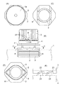
本実施形態は、パウチ容器に適用している。すなわち、図1(B)に示すように、容器は、積層フィルムを溶着して袋に構成された容器本体1と、容器本体1の縁の一部に溶着にて固定された樹脂製の注出口(スパウト)2と、注出口2を封止するねじ蓋3とから成っている。ねじ蓋3には、改竄防止のため、ピルファープルーフリング4が一体成形によって設けられている。
(1). Outline and spout of first embodiment This embodiment is applied to a pouch container. That is, as shown in FIG. 1 (B), the container is composed of a container main body 1 formed by welding a laminated film into a bag, and a resin-made note fixed to a part of the edge of the container main body 1 by welding. An outlet (spout) 2 and a
注出口2は、基本的には円筒状であり、その下部に、容器本体1を取り付けるための目玉形の溶着部5を一体に設けている。溶着部5には、溶着性を高めるためのリブ6を複数段設けている。溶着部5の上には、平面視で溶着部5の長手方向に長い略六角形の上下ガイドフランジ7,8が配置されており、溶着部5は、下ガイドフランジ8に繋がっている。なお、ガイドフランジ7,8は、容器の吊り下げに使用されるが、ねじ蓋3の開閉に際して人が指先で摘む把持部としての役割も持っている。
The
注出口2の上部には、ねじ蓋3がねじ込まれる雄ねじ9を形成しており、雄ねじ9と上ガイドフランジ7との間に、ピルファープルーフリング4を位置決めする円形の規制フランジ10を設けている。雄ねじ9は3条ねじであり、各ねじ山の始端は、周方向に略120°ずつ離れた個所に位置しており、かつ、同じ高さになっている。また、各ねじ山は、略1周程度(略360°程度)の巻量になっている。
A
注出口2のうち規制フランジ10と上ガイドフランジ7との間には、4つの本体側係合爪11を設けている。本体側係合爪11は、ピルファープルーフリング4の逆転を阻止するためのものであり、図2(E)に示すように、上下ガイドリブ7,8の長手方向と平行な線のうち、注出口2の軸心12を通る長手中心線13の個所と、長手中心線13と直交して軸心12を通る短手中心線14の個所との4か所に設けている。
Four main body
従って、本体側係合爪11は等間隔を隔てた4か所に配置されている。また、図2(E)に示すように、各本体側係合爪11においてねじ蓋3のねじ込み方向15に向いた面は、ねじ込み方向15に向かって軸心12からの距離が遠くなるように傾斜した傾斜面15aになり、ねじ蓋3のねじ戻し方向16に向いた面15bは、長手中心線13又は短手中心線14と重なるストッパー面15bになっている。
Therefore, the main body
注出口2の外面の成型は、当該注出口2の軸心と直交した方向に移動する2つの割型を使用して行われるが、割型は、注出口2の短手中心線14の方向にスライドする。従って、短手中心線14が請求項に記載した中心線になる。図2(C)及び図3(A)に、割型の移動方向を符号17で示している。図3(A)では、割型の合わせ面を符号17aで表示している。
The outer surface of the
(2).ねじ蓋
ねじ蓋3は、周壁(筒部)と天板3aとを有する下向き開口の有底筒状になっており、図2に示すように、周壁の内周には、注出口2の雄ねじ9に螺合する3条の雌ねじ18を形成している。3本の雌ねじ18の下端は、ねじ蓋3の下端部において同じ高さに揃えられている。
(2) Screw cover The
また、天板3aの下面に、注出口2の内部に嵌入する筒状の中足(シール突起)19を下向き突設している。中足19の下端部は下窄まりのテーパ部になっており、テーパ部より上の部分が注出口2の内周に密嵌する。そして、図3(B)において、中足19が注出口2に密嵌してシール機能を発揮する下向き突出寸法をE1で表示しているが、このE1の寸法を、ねじ蓋3を略半回転させたときの上下動ストロークE2と略同じ程度に設定している。
A cylindrical middle foot (seal projection) 19 that fits into the inside of the
従って、ねじ蓋3をねじ込み切った状態から半回転ほどねじ戻すと、中足19による注出口2のシール機能は解除される。換言すると、ねじ蓋3を半周程度ねじ戻すと、中足19と注出口2との摩擦抵抗は解除されて、後はねじ蓋3を抵抗無しで回転させることができる。既述のとおり、各ねじ山は、注出口2に略一周程度(360°程度)の範囲で形成しているので、ねじ蓋3は、略1回転で注出口2から取り外しできる。
Therefore, when the
図2(A)(B)に示すように、ピルファープルーフリング4は、ねじ蓋3の周壁の下端に、周方向に並んだ4つのブリッジ20によって繋がっている。ブリッジ20は、周方向に長く放射方向には薄い形態になっている。また、ピルファープルーフリング4は、上端に内向きフランジ4aを有しており、内周面には、多数の蓋側係合爪21が周方向に並んで形成されている。
As shown in FIGS. 2A and 2B, the pill
蓋側係合爪21は平面視で台形状の形態であり、ねじ蓋3のねじ込み方向15に向いた面が、ねじ込み方向に向かって軸心22の側に傾斜した傾斜面21aになっており、ねじ戻し方向16に向いた面は、軸心22を通る放射方向線と重なるストッパー面21bになっている。
The lid-
従って、ねじ蓋3のねじ込みに際しては、ピルファープルーフリング4を少し弾性変形させた状態で、蓋側係合爪21の傾斜面21aが本体側係合爪11の傾斜面15aを滑り移動することにより、ねじ蓋3のねじ込みが許容される。逆に、ねじ蓋3をねじ込み切った状態からねじ戻すと、4つの蓋側係合爪21のストッパー21bが、本体側係合爪11の4つのストッパー面11aに突っ張って、ピルファープルーフリング4は戻り回転不能に保持され、そしてブリッジ20が千切れる。
Therefore, when screwing the
図1(B)(E)に示すように、ねじ蓋3のねじ込みに際してのブリッジ20の千切れを防止するため、ねじ蓋3における周壁の下端とピルファープルーフリング4の上端面とに、ねじ込み時に当接してピルファープルーフリング4を押し回転させる嵌合溝23と、これに嵌まる嵌合突起24とを形成している。正確には、ねじ蓋3に嵌合溝23を形成して、ピルファープルーフリング4に嵌合突起24を形成している。
As shown in FIGS. 1 (B) and 1 (E), in order to prevent the
ねじ蓋3は射出成形法で製造されるが、嵌合溝23及び嵌合突起24並びにブリッジ20は、ねじ蓋3の軸心と直交した方向にスライドする一対の割型によって成形されている。従って、割型は、図1(B)を基準にして、紙面と直交した方向に移動する。図2(B)では、ねじ蓋製造用の割型の移動方向を符号26で表示している。
The
(3).位置決め手段
図3に明瞭に示すように、ねじ蓋3における周壁の内周の下端は、ピルファープルーフリング4におけるフランジ部4aの内周と略同径になっている。そして、ねじ蓋3における周壁の内周の下端部(すなわち、ねじ蓋3の開口部)に、下方と軸心22の側とに開口した環状溝27を形成し、この環状溝27に、位置決め手段を構成する3つの内向き突起28が、周方向に等間隔で形成されている。内向き突起28は、環状溝27を分断する状態に形成されており、ねじ蓋3の内周面より内側に突出していない(そうでないと型抜きできない。)。
(3). Positioning Means As clearly shown in FIG. 3, the lower end of the inner periphery of the peripheral wall of the
図2(A)に示すように、規制フランジ10の上面は下広がりに緩い角度で傾斜したテーパ面になっており、注出口2の外周面と規制フランジ10の上面とに跨がった状態で、周方向に略等間隔で、第1〜第3の3つの受け部29,30,31が形成されている。正確に述べると、注出口2の外周部のうち、注出口2の短手中心線14が通る1つの個所に第1受け部29を設け、第1受け部29からねじ込み方向15に向かって1/3回転ほど進んだ部位に第2受け部30を設け、第1受け部29からねじ込戻し方向16に向かって1/3回転ほど進んだ部位に第3受け部30を設けている。
As shown in FIG. 2 (A), the upper surface of the regulating
従って、第2受け部30と第3受け部31とは、短手中心線14を挟んだ略対称の位置に配置されており、また、第2受け部30及び第3受け部31と第1受け部29とは、長手中心線13を挟んだ両側に配置されている。
Therefore, the second receiving
そして、第1受け部29は、周方向に離れた第1正転阻止ストッパー32と、第1逆転阻止ストッパー33とのダブルストッパー部になっており、第2受け部30は、第2正転阻止とストッパー34のみを有するシングルストッパー部になっており、第3受け部31は、第3正転防止ストッパー35と第2逆転防止ストッパー36とを有するダブルストッパー部になっている。
The first receiving
正確に述べると、第1受け部29において、第1正転防止ストッパー32は、第1逆転防止ストッパー33よりもねじ込み方向15の前方に位置しており、両ストッパー32,33の間に1つの内向き突起28が嵌合する第1係合溝37が形成されている。従って、第1逆転防止ストッパー33は、ねじ蓋3の弾性変形によって内向き突起28が乗り越えできる高さ(水平方向の高さ)になっており、第1正転防止ストッパー32は、ねじ蓋3の内周面に近接しており、従って、内向き突起28が乗り越え不能な高さになっている。
To be precise, in the first receiving
従って、第1逆転防止ストッパー33の水平方向の高さは、第1正転防止ストッパー32の水平方向の高さよりも低くなっている。かつ、第1逆転防止ストッパー33のうちねじ込み方向15に向いた面は、内向き突起28の乗り越えをガイドし得る円弧面33aになっている。円弧面33aに代えて傾斜面にしてもよい。第1受け部29において、第1係合溝37の底面は注出口2の外周面になっている。従って、第1受け部の両ストッパー32,33は完全に分離している。
Accordingly, the horizontal height of the first reverse
第2正転防止ストッパー34は、内向き突起28が乗り越えできない高さになっており、ねじ蓋3の内周面に近接している。第2正転防止ストッパー34のうち、ねじ込み方向に向いていて内向き突起28が当接するストッパー面34aは、ねじ込み方向15に向けて放射方向に逃げるような傾斜面になっている。このため、内向き突起28が多少は周方向に逃げることが許容されている(成形誤差を吸収できる。)。図3(A)に示すように、第2受け部30のストッパー面34aは、注出口2の短手中心線14と平行になっている。
The second forward
第3受け部31においても、第2逆転防止ストッパー36がねじ込み方向15に向かって第3正転防止ストッパー35の後ろに位置しており、両ストッパー34,35の間に、1つの内向き突起28が嵌まる第2係合溝38が形成されている。第3受け部31において、第3正転防止ストッパー35と第2逆転防止ストッパー36とは、第2係合溝38の箇所において一連に繋がっており、繋がり部を符号38cで示している。この繋がり部38cの存在により、係合溝38の溝幅を大きくすることなく型抜きできる。
In the third receiving
また、第3受け部31においても、ねじ込み方向15に向かって、第2逆転防止ストッパー36は第3正転防止ストッパー35の後ろに位置しており、第2逆転防止ストッパー36の突出高さは、内向き突起28が乗り越えできるように、第3正転防止ストッパー36の突出高さよりも低くなっている。第3正転防止ストッパー36は、ねじ蓋3の内周面に近接しているが、軽く当接させてもよい(この点は、第1及び第2の正転防止ストッパー32,34も同様である。)。
Also in the third receiving
第3受け部31において、第2逆転防止ストッパー36のうちねじ戻し方向16に向いた面は、内向き突起28の乗り越えをガイドする円弧状ガイド面36aになっている。他方、第2係合溝38に向いた戻り防止面36bは、注出口2の短手中心線14と平行な傾斜面になっている。従って、第2逆転防止ストッパー36は山形の形態を成している。そして、戻り防止面36bが傾斜面になっていることにより、ねじ蓋3のねじ戻しに際しては、内向き突起28は、ねじ蓋3を大きく変形させることなく第2逆転防止ストッパー36を乗り越える。
In the third receiving
(4).第1実施形態のまとめ
この種のパウチ容器への内容物の充填は、注出口2から充填する場合と、注出口2とは別の個所から充填して、その個所をシールする場合との2種類がある。いずれにしても、注出口2はねじ蓋3のねじ込みによって封止される。また、ねじ蓋3をねじ込み切った状態では、既に説明したように、ピルファープルーフリング4の蓋側係合爪21が注出口2の本体側係合爪11に引っ掛かることにより、ブリッジ20を千切らないと開封できないバージン状態に保持されている。
(4). Summary of the First Embodiment This type of pouch container is filled with the contents from the
そして、ねじ蓋3のねじ込みの終期において、ねじ蓋3に設けた2つの内向き突起28が、第1及び第2の逆転防止ストッパー33,36を乗り越えてから第1及び第2の係合溝37,38に嵌合することにより、ねじ蓋3は、ねじ込み切られた状態で、振動が作用しても緩まない状態に保持される。
Then, at the end of the screwing of the
また、この状態で、3つの正転防止ストッパー32,34,35が周方向に離れた3か所においてねじ蓋3の内周面に近接又は当接しているため、ねじ蓋3の下端部は注出口2と同心に保持されており、従って、ねじ蓋3に振動が作用したり横からの外力が作用したりしても、ねじ蓋3の下端部が注出口2の軸心から偏心するようなことはなく、従って、内向き突起28が係合溝37,38から外れることはない。つまり、正転防止ストッパー32,34,35は、ねじ込み限度を規制する役割と、ねじ蓋3の下端部を注出口2と同心に保持する役割とを併有している。
Further, in this state, since the three forward
更に、2つの内向き突起28が、第2正転防止ストッパー34のストッパー面34aと、第2逆転防止ストッパー36の戻り防止面36b面とに当接しているが、これらは傾斜面になっているため、成形誤差等によって内向き突起28の位置が設計位置から周方向に多少ずれても、成形等の誤差を吸収して、ストッパー機能を確保できる。
Further, the two
そして、既述のとおり、注出口2は、その短手中心線14の方向にスライドする割型によって外面の形状が形成されるが、第2正転防止ストッパー34のストッパー面34aと、第2逆転防止ストッパー36の戻り防止面36bとはいずれも割型の移動方向と平行になっており、また、第2係合溝37は短手中心線14の方向に開口しているため、各ストッパー部32〜36は型抜きを問題なく行える状態で成形される。従って、注出口2は、製造容易でしかも高い緩み止め機能を発揮するのである。
As described above, the shape of the outer surface of the
また、第3受け部31において、第2逆転防止ストッパー36と第3正転防止ストッパー35とが第2係合溝38の箇所で一連に繋がっているため、第2係合溝38の周方向の溝幅を必要最小限度に維持できる。従って、ねじ蓋2をねじ込みきった状態での安定性に優れている(この点は,後述する実施形態も同様である。)。
Further, in the third receiving
また、ねじ蓋3を1回転ほど逆転させると注出口2から取り外されるため、開封の手間を軽減できるが、既に述べたように、ねじ蓋3を半周程度逆転させると、注出口2に対する中足19の密嵌が解除されて、ねじ蓋3の逆転に対する抵抗が無くなるため、開封を素早くしかも軽い力で行える。
Also, if the
開封に際して2つの内向き突起28が逆転防止ストッパー33,35を乗り越えるだけであることと、第2逆転防止ストッパー36の戻り防止面36bが傾斜面であることにより、内向き突起28の戻り抵抗も少ない。従って、緩み止め機能を保持しつつ、開封をできるだけ軽い力で行える。
Since the two
内向き突起28が逆転阻止ストッパー33,36に当たっている角度は、実施形態で30度程度になっているが、この程度の角度では内向き突起28は殆ど瞬間的に移動し、かつ、弾みがついているため、ねじ蓋2の回転に対して大きな抵抗になることは殆どない。従って、ねじ蓋2をスムースに回転させることができる。内向き突起28が逆転阻止ストッパー33,36に当たっている角度の好適な値はねじ蓋2の外径とも関係するが(外径が大きくなると、好適な角度は小さくなる)、おおまかには15〜40度程度が好ましく、更に好適には、20〜30度程度と推測される。
The angle at which the
本実施形態では、Lの実寸は2.5mm程度になっている。クリック感を高い状態に確保できるのは、強い擦れが生じるためであり、この場合、注出口2の外径とはあまり関係なく、内向き突起28が逆転阻止ストッパー33,30a,36′に摺接する長さが重要であると云える。大まかには、Lが1.5mm以上あるのが好ましく、更に好適には2mm以上であり、2・5〜3mm程度以上あると、より確実であると云える。
In the present embodiment, the actual size of L is about 2.5 mm. The high click feeling can be ensured by strong rubbing. In this case, the
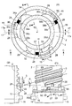
(5).第2実施形態(図4)
次に、図4に示す第2実施形態を説明する。第2実施形態は第1実施形態と相当部分が共通しており、以下では、主として相違点を説明する。第1実施形態と共通する要素は同じ符号を付しており、必要がない限り、重ねての説明は行わない。
(5) Second embodiment (FIG. 4)
Next, a second embodiment shown in FIG. 4 will be described. The second embodiment has substantially the same portions as the first embodiment, and the following mainly describes the differences. Elements common to the first embodiment are denoted by the same reference numerals, and will not be described repeatedly unless necessary.
本実施形態は、第1実施形態と同様に、周方向に等間隔で配置された第1〜第3の受け部39,30,31を有しているが、第1実施形態とは異なって、全ての受け部に逆転阻止ストッパー33,30a,36′と正転阻止ストッパー32,34,35′とを設けている。従って、第2受け部30は、第2逆転阻止ストッパー30aと第2正転阻止ストッパー34と第2係合溝38aを備えており、第3受け部31は、第3逆転阻止ストッパー36′と第3正転阻止ストッパー35′と第3係合溝38bを備えている。
This embodiment has first to
本実施形態の特徴は、各逆転阻止ストッパー33,30a,36′の周方向の長さが長いことである。具体的には、第1逆転阻止ストッパー33を例にとると、円弧面(ガイド部)33aを除いた長さLが、放射方向の突出寸法Hの2倍程度以上になっている(1・5倍以上程度であってもよい。)。従って、全長は、突出寸法Hの3倍強になっている。他の逆転阻止ストッパー30a,33も同様である。
The feature of this embodiment is that the length of each of the
さて、ねじ蓋2のねじ込みに際して、内向き突起28が逆転阻止ストッパー33,30a,36′に当たると、ねじ込みに対する抵抗が発生するため、ねじ蓋2は上向きに押される。そして、注出口2のねじ山9とねじ蓋2の雌ねじとの間には若干のクリアランスがあるため、ねじ蓋2は、いったん上昇し、次いで、弾性変形して雌ねじを雄ねじ9に突っ張らせた状態で、内向き突起28を逆転阻止ストッパー33,30a,36′に当接させた状態で回転し、最後に、内向き突起28が係合溝37,38a,38bに嵌合すると、弾性復元力が一気に開放される。
When the
この場合、逆転阻止ストッパー33,30a,36′の周方向の長さが長いことにより、内向き突起28は逆転阻止ストッパー33,30a,36′の上面に乗り上げた状態になり、従って、内向き突起28は、(C)に矢印で示すように、逆転阻止ストッパー33,30a,36′の上面を滑り移動するが、ねじ蓋2はリード角θで移動する傾向を呈するため、ねじ蓋2には強い弾性復元力が蓄えられて、内向き突起28が逆転阻止ストッパー33,30a,36′から逃げると同時に、弾性復元力は一気に開放される。この際の衝撃により、使用者は高いクリック感を感じることができる。
In this case, since the circumferential length of the reverse
更に述べると、内向き突起28が逆転阻止ストッパー33,30a,36′から逃げるときに摩擦力が一気になくなるため、カチッという音と一緒に高いクリック感を感じることができる。また、内向き突起28は、正転阻止ストッパー21,34,35に対して弾みを付けた状態で当たるめ、これによっても、カチッという音と一緒に高いクリック感を感じることができる。
More specifically, when the
逆転阻止ストッパー33,30a,36′の突出寸法と内向き突起28との関係によっては、内向き突起28が逆転阻止ストッパー33,30a,36′に上面に乗り上げずに、内向き突起28が逆転阻止ストッパー33,30a,36′の外周面を摺動することも有り得るが、この場合も、ねじ蓋2には強い弾性復元力ガ蓄えられるため、これが開放されて、内向き突起28が逆転阻止ストッパー33,30a,36′から逃げて正転阻止ストッパー21,34,35に衝突する際の衝撃は大きい。従って、この場合も高いクリック感を得ることができる。
Depending on the relationship between the protrusions of the
ねじ込みきったねじ蓋2をねじ戻す場合は、内向き突起28が逆転阻止ストッパー33,30a,36′を乗り越えるに際して、大きな弾性復元力が蓄えられてこれが一気に開放されるため、やはり、使用者は高いクリック感を感じることができる。この場合は、内向き突起28は逆転阻止ストッパー33,30a,36′から逃げるだけなので、クリック感は、大きな摩擦力が一気に無くなることによって生じていると推測される。なお、第1実施形態においても、内向き突起28が逆転阻止ストッパー33,36に当たることによってねじ蓋2がいったん上昇する現象は生じているが、その程度は小さい。
When the
(6).第3,4実施形態(図5)
第2実施形態の説明で、内向き突起28が逆転阻止ストッパー33,30a,36′の上面に乗り上げることを説明したが、図5に示す第3,4実施形態では、内向き突起28の乗り上げ現象を制御している。
(6) Third and fourth embodiments (FIG. 5)
In the description of the second embodiment, it has been described that the
このうち(A)に示す第3実施形態では、逆転阻止ストッパー33,30a,36′を第2実施形態と同じ程度の長さに設定しつつ、後半部を、ねじ込み方向に向けて低くなる傾斜面40に形成している。この例では、内向き突起28を逆転阻止ストッパー33,30a,36′に上面に確実に載せつつ、弾性復元力が過大になることを防止できる。従って、ねじ込みに要する力を抑制しつつ、高いクリック感を看取できると云える。傾斜面40はねじのリード角θと同じ程度に設定しているが、θより大きくても小さくても構わない。
In the third embodiment shown in (A), while the reverse
他方、(B)に示す第4実施形態では、逆転阻止ストッパー33,30a,36′の略前半部に、ねじ戻し方向に向けて高さが低くなる傾斜面41を形成している。この実施形態では、内向き突起28が逆転阻止ストッパー33,30a,36′の上面に乗り上げることがスムースに行われる。従って、この場合も、ねじ込みに要する力を抑制できる。いずれの実施形態においても、内向き突起28を下方に窄まる台形に形成することが可能であり、この場合は、逆転阻止ストッパー33,30a,36′への乗り上げがスムースに行われる。
On the other hand, in the fourth embodiment shown in (B), an inclined surface 41 whose height decreases in the unscrew direction is formed in the substantially front half of the reverse
図5(C)に示す第5実施形態では、逆転阻止ストッパー33,30a,36′の外角と内向き突起28の内角とに傾斜面42,43を形成して、これらの傾斜面42,43が互いに当接するように設定している。内向き突起28は、逆転阻止ストッパー33,30a,36′に当たると斜め上向きに逃げようとするが、この実施形態では、各内向き突起28の逃げがスムースになるため、ねじ蓋2の変形も均等化する。このため、よりスムースなねじ込みができると期待される。また、傾斜面42,43同士が強く密着するため、離脱するとの擦れ音も強く発生して、クリック感を一層向上できると期待される。
In the fifth embodiment shown in FIG. 5C, inclined surfaces 42, 43 are formed at the outer angles of the reverse
(7).その他
本願発明は、上記の実施形態の他にも様々に具体化できる。例えば、対象になる容器はパウチ容器には限らないのであり、例えば、樹脂製やガラス製のボトルにも適用できる。この場合は、注出口は容器本体に一体化されている。また、紙に樹脂層を設けた積層紙よりなる箱状の容器本体に注出口を取り付けた紙パックにも適用できる。
(7). Others The present invention can be embodied in various ways other than the above-described embodiment. For example, the target container is not limited to a pouch container, and may be applied to, for example, a resin or glass bottle. In this case, the spout is integrated with the container body. Also, the present invention can be applied to a paper pack in which a spout is attached to a box-shaped container body made of laminated paper having a resin layer provided on paper.
また、ねじ蓋には、必ずしもピルファープルーフリングを設ける必要はない。また、ピルファープルーフリングを設ける場合、注出口との係合手段は図示の例とは異なる構造を採用してもよい。例えば、ピルファープルーフリングの下端縁に斜め上向きの係止片を多数設けて、係止片を注出口のフランジに下方から当てることが可能である。 Further, it is not always necessary to provide a pill fur proof ring on the screw cap. When the pill fur proof ring is provided, a structure different from the illustrated example may be adopted for the means for engaging with the spout. For example, it is possible to provide a large number of obliquely upward locking pieces on the lower edge of the pill fur proof ring, and apply the locking pieces to the flange of the spout from below.
各位置決め手段において、逆転防止ストッパーの突出高さを正転防止ストッパーの突出高さより低くすることは、それ自体として独立した発明たり得る(仮に全ての位置決め手段に正転防止ストッパーと逆転防止ストッパーとがあっても、開封・封止を軽い力で行える。)。受け部を3か所に配置することも、独立した請求項たり得る。 Making the protrusion height of the reverse rotation prevention stopper lower than the protrusion height of the normal rotation prevention stopper in each of the positioning means can be an independent invention as a whole (provided that all of the positioning means have the normal rotation prevention stopper and the reverse rotation prevention stopper. Can be opened and sealed with a light force.) Arranging the receiving part in three places may also be an independent claim.
本願発明は、実際に容器に適用できる。従って、産業上利用できる。 The present invention is actually applicable to containers. Therefore, it can be used industrially.
1 容器本体の一例のパウチ容器
2 注出口
3 ねじ蓋
3a 天板
4 ピルファープルーフリング
14 短手中心線(請求項に記載した中心線)
15 ねじ込み方向(正転方向)
16 ねじ戻し方向(逆転方向)
17 割型の移動方向
17a 割型の合わせ面
19 中足
26 割型の移動方向
28 内向き突起
29 第1位置決め手段(ダブルストッパー部)
30 第2位置決め手段(シングルストッパー部)
31 第3位置決め手段(ダブルストッパー部)
32,34,35 正転防止ストッパー
33,35,30a,36,36′ 逆転防止ストッパー
35 第3正転防止ストッパー
36 第2逆転防止ストッパー
36b 戻り防止面
27,38,38a,38b 係合溝
DESCRIPTION OF SYMBOLS 1 Pouch container as an example of a container
15 Screwing direction (forward direction)
16 Screw return direction (reverse direction)
17 Split
30 Second positioning means (single stopper)
31 Third positioning means (double stopper part)
32, 34, 35 Forward
Claims (6)
前記雄ねじ及び雌ねじは3条ねじである一方、
前記中足は、前記ねじ蓋をねじ込み切った状態から半回転程度ねじ戻すと前記注出口とのシールが解除される突出寸法に設定しており、
更に、前記位置決め手段は、前記ねじ蓋の開口部に設けた内向き突起と、前記注出口の外周部に設けた受け部との対からなっており、前記複数の受け部は、前記内向き突起が当接してねじ蓋のねじ込みを阻止する正転阻止ストッパーのみで構成されたシングルストッパー部と、前記正転阻止ストッパーに加えて逆転阻止ストッパーを備えたダブルストッパー部との複数種類で構成されており、前記内向き突起は、弾性変形によって前記逆転阻止ストッパーを乗り越えるようになっている、
ねじ蓋方式容器。 A container body having a spout with an external thread formed on the outer periphery, and a screw cap with an internal thread provided on the inner circumference, and a top plate of the screw cap, for sealing tightly fitting inside the spout. A configuration in which a middle foot is provided, and a plurality of positioning means for holding the screw cap in a screwed-off state are provided in the spout and the screw cap by jumping in the circumferential direction,
The external thread and the internal thread are three-start threads,
The middle foot is set to have a protrusion dimension at which the seal with the spout is released when the screw cap is unscrewed about half a turn from the screwed state,
Further, the positioning means includes a pair of an inward projection provided at an opening of the screw cap and a receiving portion provided at an outer peripheral portion of the spout. It is composed of a plurality of types of single stoppers, each of which includes only a forward rotation preventing stopper that abuts against the protrusion to prevent the screw cap from being screwed, and a double stopper that includes a reverse rotation preventing stopper in addition to the forward rotation preventing stopper. The inward projection is configured to overshoot the reverse rotation stopper by elastic deformation.
Screw lid type container.
請求項1に記載したねじ蓋式容器。 The receiving portion and the inward projection are provided at three locations that are separated from each other in the circumferential direction. Of the three receiving portions, two receiving portions are double stopper portions, and another one is provided. The receiving part is a single stopper part,
The screw-lid type container according to claim 1.
請求項2に記載したねじ蓋式容器。 The container body has a structure in which a resin spout is welded to a bag, and an outer surface of the spout is formed by a split mold that slides in a direction orthogonal to an axis of the spout. One of the double stopper portions is located at a position of a center line passing through the axis of the spout and a line parallel to the sliding direction of the split mold, and the other one of the double stopper portion and the single stopper portion And are arranged on both sides of the center line,
The screw-lid type container according to claim 2.
前記位置決め手段は、前記ねじ蓋の開口部に設けた内向き突起と、前記注出口の外周部に設けた受け部との対からなっており、
前記複数の受け部は、前記内向き突起が当接してねじ蓋のねじ込みを阻止する正転阻止ストッパーと、前記ねじ蓋のねじ込みによって前記内向き突起が強制的に乗り越えていく逆転阻止ストッパーとからなっており、前記内向き突起と逆転阻止ストッパーとは、前記内向き突起が逆転阻止ストッパーの上面に載った状態で滑り移動する関係に設定されている、
ねじ蓋方式容器。 A container body having a spout with an external thread formed on the outer periphery, and a screw cap with an internal thread provided on the inner circumference, and a top plate of the screw cap, for sealing tightly fitting inside the spout. A configuration in which a middle foot is provided, and a plurality of positioning means for holding the screw cap in a screwed-off state are provided in the spout and the screw cap by jumping in the circumferential direction,
The positioning means comprises a pair of an inward projection provided at an opening of the screw cap and a receiving portion provided at an outer peripheral portion of the spout.
The plurality of receiving portions are composed of a forward rotation preventing stopper that contacts the inward protrusion to prevent screwing of the screw cap and a reverse rotation preventing stopper that forcibly climbs over the inward protrusion by screwing the screw cap. The inward projection and the reverse rotation stopper are set to have a relationship in which the inward projection slides and slides on the upper surface of the reverse rotation stopper.
Screw lid type container.
前記位置決め手段は、前記ねじ蓋の開口部に設けた内向き突起と、前記注出口の外周部に設けた受け部との対からなっており、
前記複数の受け部は、前記内向き突起が当接してねじ蓋のねじ込みを阻止する正転阻止ストッパーと、前記ねじ蓋のねじ込みによって前記内向き突起が強制的に乗り越えていく逆転阻止ストッパーとからなっており、
前記受け部における逆転阻止ストッパーの周方向の長さを、当該逆転阻止ストッパーが前記注出口の外周面から突出した寸法の略2〜3倍に設定している、
ねじ蓋式容器。 A container body having a spout with an external thread formed on the outer periphery, and a screw cap with an internal thread provided on the inner circumference, and a top plate of the screw cap, for sealing tightly fitting inside the spout. A configuration in which a middle foot is provided, and a plurality of positioning means for holding the screw cap in a screwed-off state are provided in the spout and the screw cap by jumping in the circumferential direction,
The positioning means comprises a pair of an inward projection provided at an opening of the screw cap and a receiving portion provided at an outer peripheral portion of the spout.
The plurality of receiving portions are composed of a forward rotation preventing stopper that contacts the inward protrusion to prevent screwing of the screw cap and a reverse rotation preventing stopper that forcibly climbs over the inward protrusion by screwing the screw cap. Has become
The circumferential length of the reverse rotation prevention stopper in the receiving portion is set to approximately two to three times the dimension of the reverse rotation prevention stopper protruding from the outer peripheral surface of the spout.
Screw lid type container.
前記位置決め手段は、前記ねじ蓋の開口部に設けた内向き突起と、前記注出口の外周部に設けた受け部との対からなっており、
前記複数の受け部は、前記内向き突起が当接してねじ蓋のねじ込みを阻止する正転阻止ストッパーと、前記ねじ蓋のねじ込みによって前記内向き突起が強制的に乗り越えていく逆転阻止ストッパーとからなっており、
前記ねじ蓋の内向き突起が前記容器本体の各逆転阻止ストッパーに摺接する角度を、15〜40度に設定している、
ねじ蓋式容器。 A container body having a spout with an external thread formed on the outer periphery, and a screw cap with an internal thread provided on the inner circumference, and a top plate of the screw cap, for sealing tightly fitting inside the spout. A configuration in which a middle foot is provided, and a plurality of positioning means for holding the screw cap in a screwed-off state are provided in the spout and the screw cap by jumping in the circumferential direction,
The positioning means comprises a pair of an inward projection provided at an opening of the screw cap and a receiving portion provided at an outer peripheral portion of the spout.
The plurality of receiving portions are composed of a forward rotation preventing stopper that contacts the inward protrusion to prevent screwing of the screw cap and a reverse rotation preventing stopper that forcibly climbs over the inward protrusion by screwing the screw cap. Has become
The angle at which the inward projection of the screw cap slides against each reverse rotation stopper of the container body is set to 15 to 40 degrees.
Screw lid type container.
Applications Claiming Priority (2)
| Application Number | Priority Date | Filing Date | Title |
|---|---|---|---|
| JP2015181910 | 2015-09-15 | ||
| JP2015181910 | 2015-09-15 |
Publications (2)
| Publication Number | Publication Date |
|---|---|
| JP2017057009A JP2017057009A (en) | 2017-03-23 |
| JP6660244B2 true JP6660244B2 (en) | 2020-03-11 |
Family
ID=58389421
Family Applications (1)
| Application Number | Title | Priority Date | Filing Date |
|---|---|---|---|
| JP2016091626A Active JP6660244B2 (en) | 2015-09-15 | 2016-04-28 | Screw lid type container |
Country Status (1)
| Country | Link |
|---|---|
| JP (1) | JP6660244B2 (en) |
Families Citing this family (5)
| Publication number | Priority date | Publication date | Assignee | Title |
|---|---|---|---|---|
| JP7213029B2 (en) * | 2018-07-04 | 2023-01-26 | 藤森工業株式会社 | Spout plug for liquid container |
| CN108974610A (en) * | 2018-09-29 | 2018-12-11 | 上海百雀羚生物科技有限公司 | A kind of drawing type bottle cap |
| JP7212250B2 (en) * | 2018-11-30 | 2023-01-25 | キョーラク株式会社 | container with cap |
| WO2020111024A1 (en) * | 2018-11-30 | 2020-06-04 | キョーラク株式会社 | Capped container, leakage examination method for double container, lamination release container, and manufacturing method therefor |
| JP7285700B2 (en) * | 2019-06-06 | 2023-06-02 | 藤森工業株式会社 | Spouting member connection structure and packaging container |
Family Cites Families (9)
| Publication number | Priority date | Publication date | Assignee | Title |
|---|---|---|---|---|
| JPS5735002Y2 (en) * | 1979-06-08 | 1982-08-03 | ||
| JPH0169746U (en) * | 1987-10-29 | 1989-05-09 | ||
| JPH10181763A (en) * | 1996-12-26 | 1998-07-07 | Dotsuji Shokai:Kk | Pour spout structure of container |
| US5938081A (en) * | 1997-08-07 | 1999-08-17 | Continental Sprayers International, Inc. | Container and cap closure |
| JP3789611B2 (en) * | 1997-08-12 | 2006-06-28 | 株式会社吉野工業所 | Extrusion container |
| JP4344411B2 (en) * | 1998-06-30 | 2009-10-14 | 大成化工株式会社 | Container with cap |
| JP2004250085A (en) * | 2003-02-21 | 2004-09-09 | Sakura Color Prod Corp | Tube container for paints |
| JP5607477B2 (en) * | 2010-09-17 | 2014-10-15 | フジモリ産業株式会社 | container |
| WO2012105605A1 (en) * | 2011-02-01 | 2012-08-09 | ロート製薬株式会社 | Liquid container |
-
2016
- 2016-04-28 JP JP2016091626A patent/JP6660244B2/en active Active
Also Published As
| Publication number | Publication date |
|---|---|
| JP2017057009A (en) | 2017-03-23 |
Similar Documents
| Publication | Publication Date | Title |
|---|---|---|
| JP6660244B2 (en) | Screw lid type container | |
| US20110147334A1 (en) | Child resistant closure with improved assembly | |
| US20080110850A1 (en) | Audible closing feature for a threaded container and lid | |
| US8123058B2 (en) | Closure with stopping mechanism | |
| US20160288967A1 (en) | Container sealing device | |
| US11511918B2 (en) | Child-resistant container having cap retainer features | |
| JP6282354B2 (en) | Improved tamper evident cover | |
| US11772860B2 (en) | Container and cap having tamper-evident member | |
| US20150122767A1 (en) | Child resistant closure with improved assembly | |
| JP6619582B2 (en) | Plastic double lid type pouring tool | |
| US20150014269A1 (en) | Senior friendly child resistant closure | |
| JP6143342B2 (en) | Container with screw cap | |
| JP5679879B2 (en) | Safety lid | |
| JP2010070230A (en) | Cap | |
| JP2007514612A (en) | Screw cap for containers | |
| GB2512620A (en) | Tamper Evident Child Resistant Flip-Top Closure | |
| US20150298876A1 (en) | Tamper evident closure | |
| JP5696374B2 (en) | Pouch outlet plug and pouch using the same | |
| JP2009544543A (en) | Packaged goods | |
| JP4934448B2 (en) | Plastic cap | |
| JP5984636B2 (en) | Container lid composed of inner stopper and lid body | |
| JP5893851B2 (en) | cartridge | |
| JP7466828B2 (en) | Plastic container lid | |
| JP7466827B2 (en) | Plastic container lid | |
| JP2024000789A (en) | One piece cap and combination between the same and container |
Legal Events
| Date | Code | Title | Description |
|---|---|---|---|
| A621 | Written request for application examination |
Free format text: JAPANESE INTERMEDIATE CODE: A621 Effective date: 20190124 |
|
| A977 | Report on retrieval |
Free format text: JAPANESE INTERMEDIATE CODE: A971007 Effective date: 20191111 |
|
| A131 | Notification of reasons for refusal |
Free format text: JAPANESE INTERMEDIATE CODE: A131 Effective date: 20191120 |
|
| A521 | Request for written amendment filed |
Free format text: JAPANESE INTERMEDIATE CODE: A523 Effective date: 20191211 |
|
| TRDD | Decision of grant or rejection written | ||
| A01 | Written decision to grant a patent or to grant a registration (utility model) |
Free format text: JAPANESE INTERMEDIATE CODE: A01 Effective date: 20200108 |
|
| A61 | First payment of annual fees (during grant procedure) |
Free format text: JAPANESE INTERMEDIATE CODE: A61 Effective date: 20200207 |
|
| R150 | Certificate of patent or registration of utility model |
Ref document number: 6660244 Country of ref document: JP Free format text: JAPANESE INTERMEDIATE CODE: R150 |
|
| R250 | Receipt of annual fees |
Free format text: JAPANESE INTERMEDIATE CODE: R250 |
|
| R250 | Receipt of annual fees |
Free format text: JAPANESE INTERMEDIATE CODE: R250 |