JP5969141B2 - Fully assembled, overall placement complex type housing and its construction method - Google Patents
Fully assembled, overall placement complex type housing and its construction method Download PDFInfo
- Publication number
- JP5969141B2 JP5969141B2 JP2015548157A JP2015548157A JP5969141B2 JP 5969141 B2 JP5969141 B2 JP 5969141B2 JP 2015548157 A JP2015548157 A JP 2015548157A JP 2015548157 A JP2015548157 A JP 2015548157A JP 5969141 B2 JP5969141 B2 JP 5969141B2
- Authority
- JP
- Japan
- Prior art keywords
- reinforcing bar
- members
- connection block
- wall
- rebar
- Prior art date
- Legal status (The legal status is an assumption and is not a legal conclusion. Google has not performed a legal analysis and makes no representation as to the accuracy of the status listed.)
- Expired - Fee Related
Links
Images


Classifications
-
- E—FIXED CONSTRUCTIONS
- E04—BUILDING
- E04C—STRUCTURAL ELEMENTS; BUILDING MATERIALS
- E04C3/00—Structural elongated elements designed for load-supporting
- E04C3/02—Joists; Girders, trusses, or trusslike structures, e.g. prefabricated; Lintels; Transoms; Braces
- E04C3/29—Joists; Girders, trusses, or trusslike structures, e.g. prefabricated; Lintels; Transoms; Braces built-up from parts of different material, i.e. composite structures
- E04C3/293—Joists; Girders, trusses, or trusslike structures, e.g. prefabricated; Lintels; Transoms; Braces built-up from parts of different material, i.e. composite structures the materials being steel and concrete
- E04C3/294—Joists; Girders, trusses, or trusslike structures, e.g. prefabricated; Lintels; Transoms; Braces built-up from parts of different material, i.e. composite structures the materials being steel and concrete of concrete combined with a girder-like structure extending laterally outside the element
-
- E—FIXED CONSTRUCTIONS
- E04—BUILDING
- E04C—STRUCTURAL ELEMENTS; BUILDING MATERIALS
- E04C5/00—Reinforcing elements, e.g. for concrete; Auxiliary elements therefor
- E04C5/01—Reinforcing elements of metal, e.g. with non-structural coatings
- E04C5/06—Reinforcing elements of metal, e.g. with non-structural coatings of high bending resistance, i.e. of essentially three-dimensional extent, e.g. lattice girders
- E04C5/0604—Prismatic or cylindrical reinforcement cages composed of longitudinal bars and open or closed stirrup rods
- E04C5/0618—Closed cages with spiral- or coil-shaped stirrup rod
-
- E—FIXED CONSTRUCTIONS
- E04—BUILDING
- E04B—GENERAL BUILDING CONSTRUCTIONS; WALLS, e.g. PARTITIONS; ROOFS; FLOORS; CEILINGS; INSULATION OR OTHER PROTECTION OF BUILDINGS
- E04B1/00—Constructions in general; Structures which are not restricted either to walls, e.g. partitions, or floors or ceilings or roofs
- E04B1/16—Structures made from masses, e.g. of concrete, cast or similarly formed in situ with or without making use of additional elements, such as permanent forms, substructures to be coated with load-bearing material
- E04B1/161—Structures made from masses, e.g. of concrete, cast or similarly formed in situ with or without making use of additional elements, such as permanent forms, substructures to be coated with load-bearing material with vertical and horizontal slabs, both being partially cast in situ
-
- E—FIXED CONSTRUCTIONS
- E04—BUILDING
- E04B—GENERAL BUILDING CONSTRUCTIONS; WALLS, e.g. PARTITIONS; ROOFS; FLOORS; CEILINGS; INSULATION OR OTHER PROTECTION OF BUILDINGS
- E04B5/00—Floors; Floor construction with regard to insulation; Connections specially adapted therefor
- E04B5/16—Load-carrying floor structures wholly or partly cast or similarly formed in situ
- E04B5/17—Floor structures partly formed in situ
- E04B5/23—Floor structures partly formed in situ with stiffening ribs or other beam-like formations wholly or partly prefabricated
- E04B5/29—Floor structures partly formed in situ with stiffening ribs or other beam-like formations wholly or partly prefabricated the prefabricated parts of the beams consisting wholly of metal
-
- E—FIXED CONSTRUCTIONS
- E04—BUILDING
- E04H—BUILDINGS OR LIKE STRUCTURES FOR PARTICULAR PURPOSES; SWIMMING OR SPLASH BATHS OR POOLS; MASTS; FENCING; TENTS OR CANOPIES, IN GENERAL
- E04H1/00—Buildings or groups of buildings for dwelling or office purposes; General layout, e.g. modular co-ordination or staggered storeys
- E04H1/12—Small buildings or other erections for limited occupation, erected in the open air or arranged in buildings, e.g. kiosks, waiting shelters for bus stops or for filling stations, roofs for railway platforms, watchmen's huts or dressing cubicles
-
- E—FIXED CONSTRUCTIONS
- E04—BUILDING
- E04B—GENERAL BUILDING CONSTRUCTIONS; WALLS, e.g. PARTITIONS; ROOFS; FLOORS; CEILINGS; INSULATION OR OTHER PROTECTION OF BUILDINGS
- E04B2/00—Walls, e.g. partitions, for buildings; Wall construction with regard to insulation; Connections specially adapted to walls
- E04B2/84—Walls made by casting, pouring, or tamping in situ
- E04B2/86—Walls made by casting, pouring, or tamping in situ made in permanent forms
- E04B2/8647—Walls made by casting, pouring, or tamping in situ made in permanent forms with ties going through the forms
-
- E—FIXED CONSTRUCTIONS
- E04—BUILDING
- E04B—GENERAL BUILDING CONSTRUCTIONS; WALLS, e.g. PARTITIONS; ROOFS; FLOORS; CEILINGS; INSULATION OR OTHER PROTECTION OF BUILDINGS
- E04B5/00—Floors; Floor construction with regard to insulation; Connections specially adapted therefor
- E04B5/16—Load-carrying floor structures wholly or partly cast or similarly formed in situ
- E04B5/17—Floor structures partly formed in situ
- E04B5/18—Floor structures partly formed in situ with stiffening ribs or other beam-like formations wholly cast between filling members
- E04B5/21—Cross-ribbed floors
-
- E—FIXED CONSTRUCTIONS
- E04—BUILDING
- E04C—STRUCTURAL ELEMENTS; BUILDING MATERIALS
- E04C3/00—Structural elongated elements designed for load-supporting
- E04C3/02—Joists; Girders, trusses, or trusslike structures, e.g. prefabricated; Lintels; Transoms; Braces
- E04C3/04—Joists; Girders, trusses, or trusslike structures, e.g. prefabricated; Lintels; Transoms; Braces of metal
- E04C3/08—Joists; Girders, trusses, or trusslike structures, e.g. prefabricated; Lintels; Transoms; Braces of metal with apertured web, e.g. with a web consisting of bar-like components; Honeycomb girders
-
- E—FIXED CONSTRUCTIONS
- E04—BUILDING
- E04C—STRUCTURAL ELEMENTS; BUILDING MATERIALS
- E04C5/00—Reinforcing elements, e.g. for concrete; Auxiliary elements therefor
- E04C5/01—Reinforcing elements of metal, e.g. with non-structural coatings
- E04C5/02—Reinforcing elements of metal, e.g. with non-structural coatings of low bending resistance
- E04C5/04—Mats
-
- E—FIXED CONSTRUCTIONS
- E04—BUILDING
- E04C—STRUCTURAL ELEMENTS; BUILDING MATERIALS
- E04C5/00—Reinforcing elements, e.g. for concrete; Auxiliary elements therefor
- E04C5/01—Reinforcing elements of metal, e.g. with non-structural coatings
- E04C5/06—Reinforcing elements of metal, e.g. with non-structural coatings of high bending resistance, i.e. of essentially three-dimensional extent, e.g. lattice girders
- E04C5/065—Light-weight girders, e.g. with precast parts
Description
本発明は建物(住宅)及び構築技術の技術分野に関し、具体的には完全組立、全体打設複合型住宅及びその構築方法に関する。 The present invention relates to the technical field of buildings (housing) and construction technology, and more specifically, to a fully assembled and totally cast composite housing and a construction method thereof.
衣食住、交通は、人々が日常で直面するものであり、住宅は人々の幸せにつながる。社会の進歩に伴って、住宅に対する人々の要求も向上しつつあり、最初は風や雨から身を守ることのみが求められ、今は温かく快適で、防音、防火機能、ひいては一定の自然災害を抵抗する能力、たとえば耐震能力を持つことも求されている。中国の急速な発展に伴って、人々の生活品質が向上し、断熱と省エネルギーも、日程に上っている。そして、大量の需要、大量の建設は、天然資源への需要も拡げつつあり、大気の汚染を悪化させ、従って、材料節約、環境に優しい工事過程も求められつつある。国家は建築施工を工場化、産業化、集約化することを提案したが、従来の住宅構造形態は、以上のすべての要件を同時に満たすことが困難である。 Food, food and housing, transportation is what people face every day, and housing leads to happiness. With societal progress, people's demands for housing are also increasing. At first, they only need to protect themselves from wind and rain, and now they are warm and comfortable, soundproofing, fireproofing, and certain natural disasters. It is also required to have the ability to resist, for example, earthquake resistance. With the rapid development of China, people's quality of life has improved, and heat insulation and energy saving are also on schedule. In addition, a large amount of demand and a large amount of construction are also increasing the demand for natural resources, worsening air pollution, and therefore, material saving and environmentally friendly construction processes are also being sought. Although the state has proposed building, industrializing and consolidating building construction, the conventional housing structure form is difficult to satisfy all the above requirements at the same time.
従来の低層住宅でも中高層住宅建築でも、通常は、鉄筋コンクリートラーメン構造、壁式ラーメン構造、鉄骨柱内にコンクリートを打設してなるラーメン構造、鋼構造であり、従来の住宅建築はほとんどこれらの構造形態であり、これらの構造の施工過程は、通常、構造本体の施工、間仕切り壁の築き、内壁のプラスタ塗り装飾、外部断熱施工、外部装飾施工に分けられる。施工周期はいずれも長く、且つ現場で大量の人工によるウェット作業が行われ、大量の型枠の取り外しが必要であり、外部断熱施工中に防火において潜在的なリスクが存在するため、省エネルギーと環境保護、材料節約、工場化、産業化、集約化生産の要件を満たすことができない。 Conventional low-rise and medium- and high-rise residential buildings are usually reinforced concrete ramen structures, wall-type ramen structures, ramen structures in which concrete is placed in steel columns, and steel structures. The construction process of these structures is usually divided into construction of the structure body, construction of partition walls, plaster decoration on the inner wall, external heat insulation construction, and external decoration construction. The construction cycle is long, and a lot of artificial wet work is performed at the site, a large amount of formwork needs to be removed, and there is a potential risk in fire protection during external insulation construction. The requirements of protection, material saving, factoryization, industrialization and centralized production cannot be met.
従来の技術における欠陥に対して、本発明の目的は完全組立、全体打設複合型住宅及びその構築方法を提供し、技術がシンプルで、実施しやく、各部材の仕様が同じで、汎用性が優れており、組み立てが便利で迅速、全体の安定性が良好であり、防火、耐水、防音性能が良好であり、省エネと環境保護、材料節約、工場化、産業化、集約化生産の要件を満たす。 In contrast to the defects in the prior art, the object of the present invention is to provide a complete assembly, an overall placement complex type house and its construction method, the technology is simple, easy to implement, the specifications of each member are the same, and versatility Excellent assembly, convenient and quick, good overall stability, good fireproof, waterproof, soundproof performance, energy saving and environmental protection, material saving, factoryization, industrialization, centralized production requirements Meet.
以上の目的を達成するために、本発明は以下の技術案を採用する。 In order to achieve the above object, the present invention adopts the following technical solution.
住宅基礎の上に設置された少なくとも1階の住宅本体を含み、前記住宅本体は壁1、床スラブ2、ドア3及び窓4を備える完全組立、全体打設複合型住宅であって、前記住宅本体の各階はいずれも筋、髓、皮、骨の四大システムからなり、各システムは1つまたは複数の部材を備え、そのうち、
筋システムは、壁1または床スラブ2の張力支持ネットワーク体系を構成するとともに、壁1にドア3及び窓4を取り付けるための空間を予め確保し、垂直方向鉄筋柱部材5と、水平方向鉄筋柱部材6と、鉄筋メッシュ部材7と、第1の屋根トラス梁部材8と、第2の屋根トラス梁部材9と、を備え、
髓システムは、壁1または床スラブ2の張力支持ネットワーク体系を安定化させるとともに、筋システムの部材と皮システムの部材を接続することに用いられ、接続ブロック部材11と、接続ブロック締め具部材14と、屋根下型19と、を備え、
皮システムは、壁1の外断熱層及び内防火層体系を構成するとともに、骨システムが1回打設成型で筋システム、髓システム及び皮システムの部材を接続する場合、打設時の型枠及び支持体系としての役割を果たすものであり、壁板部材20を備え、
骨体系は、壁1または床スラブ2の受圧体系を構成し、高強度自己充填性流動モルタルであり、全体打設技術で壁1と床スラブ2を1回打設成型し、筋システム、髓システム及び皮システムを一体に接続し、複合式スチールメッシュセメント多層構造の耐力層を形成することを特徴とする完全組立、全体打設複合型住宅。
A housing body at least on the first floor installed on a housing foundation, wherein the housing body is a fully assembled, fully cast composite housing comprising a
The reinforcement system constitutes a tension support network system for the
The heel system is used to stabilize the tension support network system of the
The skin system constitutes the outer heat insulation layer and inner fire protection layer system of the
The bone system is the pressure receiving system of the
上記技術案に基づいて、前記高強度自己充填性流動モルタルは、
スランプが28cm以上であり、且つスランプが1時間ほどでゼロに減衰することと、
流動性が20〜25分間保持されることと、
初期凝結時間が1.5時間であることと、
強度が建物階数に応じて30MPa、35MPa、40Mpa、45MPaの4種に分けられることと、という技術要件を満たす。
Based on the above technical solution, the high-strength self-filling flow mortar is
The slump is 28 cm or more and the slump decays to zero in about an hour;
Fluidity is maintained for 20-25 minutes;
The initial setting time is 1.5 hours;
The technical requirement that the strength is divided into four types of 30 MPa, 35 MPa, 40 Mpa, and 45 MPa according to the building floor number is satisfied.
上記技術案に基づいて、前記接続ブロック部材11及び壁板部材20はいずれも気泡コンクリートブロックであり、前記気泡コンクリートブロックはセメントを基材として基材中にフライアッシユを加えて製造され、軽い建築材料モジュールに属する。
Based on the above technical solution, both the
上記技術案に基づいて、前記壁1の張力支持ネットワーク体系は、垂直方向鉄筋柱部材5と水平方向鉄筋柱部材6を接合してなる鉄筋トラスを備え、垂直方向鉄筋柱部材5を壁の支持柱とし、水平方向鉄筋柱部材6を大引または上部臥梁とする。
Based on the above technical solution, the tension support network system of the
隣接する垂直方向鉄筋柱部材5の柱間軸心距離は15〜60cmである。
The inter-column axial distance between adjacent vertical
隣接する垂直方向鉄筋柱部材5の上下両端はそれぞれ鉄筋の殺ぎ次ぎで上部臥梁または大引としての水平方向鉄筋柱部材6に接続される。
The upper and lower ends of the adjacent vertical
大引としての水平方向鉄筋柱部材6は鉄筋の殺ぎ次ぎで建物の基礎に固定される。
The horizontal
ドアまたは窓を取り付ける必要がある位置に、垂直方向鉄筋柱部材5と水平方向鉄筋柱部材6を垂直接続して予め確保したドア取り付け領域33または予め確保された窓取り付け領域44を構成る。
The vertical
鉄筋メッシュ部材7は接続鉄筋で垂直方向鉄筋柱部材5と水平方向鉄筋柱部材6の内外両側に固定される。
The reinforcing
前記床スラブ2の張力支持ネットワーク体系は、複数の平行に配置された第2の屋根トラス梁部材9を備え、前記第2の屋根トラス梁部材9上に第1の屋根トラス梁部材8を貫装するための切欠き10が設けられる。
The tension support network system of the floor slab 2 includes a plurality of parallelly arranged second roof
複数の第1の屋根トラス梁部材8はそれぞれ第2の屋根トラス梁部材9の切欠き10内に貫装され、且つ第1の屋根トラス梁部材8と第2の屋根トラス梁部材9は垂直接続して格子状になる。
Each of the plurality of first roof
上記技術案に基づいて、第1の屋根トラス梁部材8と第2の屋根トラス梁部材9が垂直接続して格子状の床スラブ2の張力支持ネットワーク体系を構成した後、屋根下型19は第1の屋根トラス梁部材8及び第2の屋根トラス梁部材9の下部に固定され、屋根ハニカム体系を構成する。
Based on the above technical solution, after the first roof
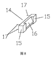
上記技術案に基づいて、前記接続ブロック部材11の全体は1つの長方形ブロックであり、その四角にいずれも斜面12が設けられ、ブロック上に少なくとも4つごとの接続ブロック貫通孔13が設けられる。
Based on the above technical solution, the
前記接続ブロック締め具部材14の全体はストリップ状であり、その幅が垂直方向鉄筋柱部材5と同じであり、その長さ方向に沿う2つの対向する側面には、そのうちの一方の側面に複数の固定鉄筋17が設けられ、他方の側面の中部にスロープ16が設けられ、スロープ16の幅が接続ブロック部材における斜面12の幅と適応する。
The entire connection
隣接する2つの垂直方向鉄筋柱部材5上に、4つごとの接続ブロック締め具部材14を1組として長方形状に分布し、接続ブロック部材11の高さに応じて2つの垂直方向鉄筋柱部材5に固定され、4つの接続ブロック締め具部材14におけるスロープ16はそれぞれブロック部材11の1つの角を固定接続し、接続ブロック部材11の四角の斜面12は接続ブロック締め具部材14のスロープ16に接触し、スロープ16及び接続ブロック締め具部材14の端部15で制限され、接続ブロック部材11を垂直方向鉄筋柱部材5に固定する。
On the two adjacent vertical
上記技術案に基づいて、前記壁板部材20に少なくとも4つの壁板貫通孔21が設けられる。
Based on the above technical solution, the
壁板部材20は垂直方向鉄筋柱部材5と水平方向鉄筋柱部材6の内外両側に位置する鉄筋メッシュ部材7上にそれぞれ取り付けられ、ボルトは壁板貫通孔21と接続ブロック貫通孔13を順に通り抜けて接続ブロック部材11とその内外両側の壁板部材20を一体に接続する。
The
完全組立、全体打設複合型住宅の構築方法であって、
建物の基礎工事が完了した後、大引としての水平方向鉄筋柱部材6を壁方向に沿って設置し、且つ鉄筋の殺ぎ次ぎで建物の基礎に固定するステップ1と、
垂直方向鉄筋柱部材5と大引としての水平方向鉄筋柱部材6を垂直接続し、隣接する垂直方向鉄筋柱部材5の柱間軸心距離は15〜60cmであるステップ2と、
垂直方向鉄筋柱部材5のトップエンドを鉄筋の殺ぎ次ぎで上部臥梁としての水平方向鉄筋柱部材6に接続して、鉄筋トラスを構成し、
ドアまたは窓を取り付ける必要がある位置に、垂直方向鉄筋柱部材5と水平方向鉄筋柱部材6を垂直接続して予め確保したドア取り付け領域33または予め確保された窓取り付け領域44を構成するステップ3と、
各々の接続ブロック部材11の四角にそれぞれ1つの接続ブロック締め具部材14を設置するように、予め確保されたドア取り付ける領域33及び予め確保された窓取り付ける領域44以外、あらゆる隣接する2つの垂直方向鉄筋柱部材5及び水平方向鉄筋柱部材6で取り囲まれた空間にいずれも接続ブロック部材11が完全に取り付けられるまで、接続ブロック部材11を4つごとの接続ブロック締め具部材14で隣接する2つの垂直方向鉄筋柱部材5上に組み立てるステップ4と、
2つの鉄筋メッシュ部材7をそれぞれ接続鉄筋で垂直方向鉄筋柱部材5と水平方向鉄筋柱部材6の内外両側に固定し、鉄筋メッシュ部材7、垂直方向鉄筋柱部材5と水平方向鉄筋柱部材6で構成されるトラス体を形成するステップ5と、
壁板部材20を垂直方向鉄筋柱部材5と水平方向鉄筋柱部材6の内外両側に配置し、ボルトが一方の側壁板部材、接続ブロック部材、他方の側壁板部材を順に通り抜けることにより、三者とトラス体を一体に固定するステップ6と、
第1の屋根トラス梁部材8と第2の屋根トラス梁部材9を垂直接続して格子状の空間ネットラックを構成し、該空間ネットラックはすなわち床スラブ2の張力支持ネットワーク体系であるステップ7と、
屋根下型19を第1の屋根トラス梁部材8及び第2の屋根トラス梁部材9の下部に固定し、屋根ハニカム体系を構成するステップ8と、
各部材間のスリットをポインティングし、高強度自己充填性流動モルタルを現場打ちする時のモルタルの漏れを防止するステップ9と、
全体打設技術で壁1と床スラブ2を1回打設成型し、筋システム、髓システム及び皮システムを一体に接続し、複合式スチールメッシュセメント多層構造の耐力層を形成するステップ10と、を含むことを特徴とする完全組立、全体打設複合型住宅の構築方法。
It is a method of constructing a fully assembled and fully cast composite house,
After the foundation work of the building is completed, the
Step 2 in which the vertical
Connecting the top end of the vertical
Any two adjacent vertical directions other than the pre-secured
The two reinforcing
By arranging the
The first roof
A
上記技術案に基づいて、前記全体打設技術の具体的なステップは、建物の階全体の各壁の現場打ちの均一性を保証するように、高強度自己充填性流動モルタルを主管及び分岐管で、それぞれ共通階の各部屋の四角に輸送し、多点の同時打設を行う。 Based on the above technical proposal, the concrete step of the overall placing technique is to make the high strength self-filling flow mortar the main pipe and the branch pipe so as to ensure the uniformity of the on-site strike of each wall of the entire floor of the building. Then, they are transported to the squares of each room on the common floor, and multiple points are placed simultaneously.
打設速度は、以下の技術的パラメータコントロールで制御され、即ち、時間ごとの打設高さが30cm以内であり、打設時のセメントモルタルの側圧力が安全使用範囲内に確保される。 The placement speed is controlled by the following technical parameter control, that is, the placement height per hour is within 30 cm, and the side pressure of the cement mortar at the placement is ensured within the safe use range.
上記技術案に基づいて、住宅本体の階数が2階又はそれ以上である場合、ステップ6で壁板部材20を取り付ける前、まず次の階の垂直方向鉄筋柱部材5のトップエンドに鉄筋の殺ぎ次ぎで上の階の垂直方向鉄筋柱部材5を固定し、且つステップ2〜5を繰り返し、上階壁の鉄筋トラス、接続ブロック締め具部材14、接続ブロック部材11、トラス体を敷設してから、下階壁及び床スラブの構築ステップ6〜10を行う。
Based on the above technical plan, when the number of floors of the housing body is two floors or more, before the
本発明に係る完全組立、全体打設複合型住宅及びその構築方法は、技術がシンプルで、実施しやく、各部材の仕様が同じで、汎用性が優れており、組み立てが便利で迅速、住宅全体の安定性が良好で、防火、耐水、防音性能が良好であり、省エネと環境保護、材料節約、工場化、産業化、集約化生産の要件を満たす。 The complete assembly, overall placement composite type housing and its construction method according to the present invention are simple in technology, easy to implement, have the same specifications for each member, have excellent versatility, and are convenient and quick to assemble. Overall stability is good, fireproof, waterproof, soundproof performance is good, meeting the requirements of energy saving and environmental protection, material saving, factoryization, industrialization, centralized production.
以下、図面を参照しながら本発明を更に詳細に説明する。 Hereinafter, the present invention will be described in more detail with reference to the drawings.
本発明の主なる趣旨は、建物全体の住宅基礎の上に位置する住宅主体を、各階をいずれも生命構造における筋、髓、皮、骨の機能に応じて、4つのシステムに分け、各システムを更に1つまたは複数の部材(標準化部材)に分け、ある階の住宅本体の筋、髓、皮の3つのシステムの部材を組み立て済後、骨システムとしてのモルタルに1回打設成型技術を用い、筋、髓、皮の3つのシステムの部材を一体に接続して、複合式多層構造を形成し、全体打設された建物が独立ユニットボディ構造になるとともに、防火、断熱、遮音及び耐震の機能を兼ね備え、建物の重量を最大限に軽減し、各種の補助材料の使用を減少させ、現場の施工時の工程を減少させ、大量の人力及び材料を減少させ、それにより、建物が省エネルギー・環境保護、材料節約、工場化、産業化、集約化生産の要件を満たす。前記建物の基礎は従来の建物の基礎を用い、従来の周知技術で達成することができ、繰り返して詳しく説明しない。 The main purpose of the present invention is to divide the main body located on the foundation of the entire building into four systems according to the functions of muscles, folds, skins and bones in the life structure. Is further divided into one or more members (standardized members), and after the assembly of the three system members of the main body of the house on one floor, the muscles, the heels, and the skin, it is once molded into a mortar as a bone system. The three components of the muscle, heel, and skin are connected together to form a composite multi-layer structure, and the entire building is an independent unit body structure. Combines seismic functions, maximizes the weight of the building, reduces the use of various auxiliary materials, reduces the site construction process, reduces the amount of manpower and materials, thereby Energy saving and environmental protection, material section , Meet the factory of, industrialization, of consolidating production requirements. The building foundation may be a conventional building foundation, which may be achieved by conventional well-known techniques and will not be described in detail again.
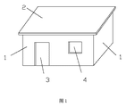
図1〜10に示すように、本発明に係る完全組立、全体打設複合型住宅は、住宅基礎の上に設置された少なくとも1階の住宅本体を含み、前記住宅本体は壁1、床スラブ2、ドア3及び窓4を備え、壁1は住宅本体を少なくとも1つの部屋に区画され、床スラブ2は各階の間の仕切り部または最上階の屋根とされ、
前記住宅本体の各階はいずれも筋、髓、皮、骨の四大システムからなり、各システムは1つまたは複数の部材を備え、そのうち、
筋システムは、構成壁1または床スラブ2の張力支持ネットワーク体系を構成するとともに、壁1にドア3及び窓4を取り付ける空間を予め確保し、垂直方向鉄筋柱部材5と、水平方向鉄筋柱部材6と、鉄筋メッシュ部材7と、第1の屋根トラス梁部材8と、第2の屋根トラス梁部材9と、を備え、
髓システムは、壁1または床スラブ2の張力支持ネットワーク体系を安定化させるとともに、筋システムの部材と皮システムの部材を接続することに用いられ、接続ブロック部材11、接続ブロック締め具部材14及び屋根下型19を備え、
皮システムは、壁1の外断熱層及び内防火層体系を構成するとともに、骨システムが1回打設成型で筋システム、髓システム及び皮システムの部材を接続する場合、打設時の型枠及び支持体系としての役割を果たすものであり、壁板部材20を備え、
骨体系は、壁1または床スラブ2の受圧体系を構成し、高強度自己充填性流動モルタルであり、全体打設技術で壁1と床スラブ2を1回打設成型し、筋システム、髓システム及び皮システムを一体に接続し、複合式スチールメッシュセメント多層構造の耐力層を形成する。そのうち、壁1の耐力骨層の厚みは2.5〜4cm、床スラブ2の厚みは15〜25cmであり、壁1の耐力骨層の厚みは接続ブロック締め具部材14と壁板部材20との間の距離が2.5〜4cmであることを意味し、この隙間に高強度自己充填性流動モルタルを打設してから、前記壁1の耐力骨層を形成する。
As shown in FIGS. 1 to 10, the fully assembled and overall placement composite type housing according to the present invention includes at least a first-floor housing body installed on a housing foundation, and the housing body includes a
Each floor of the housing body is composed of four major systems of muscle, heel, skin, and bone, each system comprising one or more members,
The reinforcement system constitutes a tension support network system of the
The scissor system is used to stabilize the tension support network system of the
The skin system constitutes the outer heat insulation layer and inner fire protection layer system of the
The bone system is the pressure receiving system of the
本発明に係る完全組立、全体打設複合型住宅は、壁1または床スラブ2を現場で同時に全体打設し、整合性が良好であり、耐震性能が優れており、良好な弾塑性の力学的特性を有し、せん断耐力が高く、建物は防火、断熱、遮音及び耐震の機能を具備し、そのうち、皮システムは、装飾、防火、断熱機能を有し、髓システムは内部防音効果を強化し、組み立て、全体打設の時、型枠及び支柱を加える必要がなく、壁は普通のコンクリート剪断壁に比べて、50%以上のコンクリートを節約することができ、建築全体の自重を50%軽減することができる。
The fully assembled and totally cast composite house according to the present invention has the
上記技術案に基づいて、前記高強度自己充填性流動モルタルは、 スランプが28cm以上であり、且つスランプが1時間(±10分間)ほどゼロに減衰することと、
流動性が20〜25分間保持されることと、
初期凝結時間が1.5時間であることと、
強度が建物階数に応じて30MPa、35MPa、40Mpa、45MPaの4種に分けられることと、という技術条件を満たす。
Based on the above technical solution, the high-strength self-filling flow mortar has a slump of 28 cm or more, and the slump attenuates to zero for about 1 hour (± 10 minutes);
Fluidity is maintained for 20-25 minutes;
The initial setting time is 1.5 hours;
The technical condition that the strength is divided into four types of 30 MPa, 35 MPa, 40 Mpa, and 45 MPa according to the building floor number is satisfied.
上記技術案に基づいて、前記垂直方向鉄筋柱部材5及び水平方向鉄筋柱部材6はいずれも螺旋鉄筋四角柱である。
Based on the above technical solution, both the vertical
上記技術案に基づいて、前記接続ブロック部材11及び壁板部材20はいずれも気泡コンクリートブロックであり、前記気泡コンクリートブロックはセメントを基材として基材中にフライアッシユを加えて製造され、軽い建築材料モジュールに属する。フライアッシユを加える目的は部材の耐火性能を向上させることである。
Based on the above technical solution, both the
上記技術案に基づいて、接続ブロック部材11及び壁板部材20の表面はいずれも強化処理され、型枠として高強度自己充填性流動モルタルの現場打ちの時に生じた型枠への側圧力を受ける能力を具備する。
Based on the above technical proposal, the surfaces of the
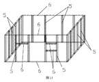
上記技術案に基づいて、図11、13に示すように、前記壁1の張力支持ネットワーク体系は、垂直方向鉄筋柱部材5と水平方向鉄筋柱部材6を接合してなる鉄筋トラスを備え、垂直方向鉄筋柱部材5を壁の支持柱とし、水平方向鉄筋柱部材6を大引または上部臥梁とする。
Based on the above technical solution, as shown in FIGS. 11 and 13, the tension support network system of the
隣接する垂直方向鉄筋柱部材5の柱間軸心距離は15〜60cm、たとえば、柱間軸心距離は15cm、30cmまたは60cmである。
The inter-column axial distance between adjacent vertical reinforcing
隣接する垂直方向鉄筋柱部材5の上下両端はそれぞれ鉄筋の殺ぎ次ぎで上部臥梁または大引としての水平方向鉄筋柱部材6に接続される。
The upper and lower ends of the adjacent vertical reinforcing
大引としての水平方向鉄筋柱部材6は鉄筋の殺ぎ次ぎで建物の基礎に固定される。
The horizontal
ドアまたは窓を取り付ける必要がある位置に、垂直方向鉄筋柱部材5と水平方向鉄筋柱部材6を垂直接続して予め確保したドア取り付け領域33または予め確保された窓取り付け領域44を構成する。
The vertical
鉄筋メッシュ部材7は接続鉄筋で垂直方向鉄筋柱部材5と水平方向鉄筋柱部材6の内外両側に固定され、前記内外両側はそれぞれ部屋内部及び部屋外部に対応する。
The reinforcing
図5、6、14に示すように、前記床スラブ2の張力支持ネットワーク体系は、複数の平行に配置された第2の屋根トラス梁部材9を備え、前記第2の屋根トラス梁部材9上に第1の屋根トラス梁部材8を貫装するための切欠き10が設けられ、切欠き10が少なくとも1つ設置される。
As shown in FIGS. 5, 6, and 14, the tension support network system of the floor slab 2 includes a plurality of parallelly arranged second roof
複数の第1の屋根トラス梁部材8はそれぞれ第2の屋根トラス梁部材9の切欠き10内に貫装され、且つ第1の屋根トラス梁部材8と第2の屋根トラス梁部材9は垂直接続して格子状になる。
Each of the plurality of first roof
上記技術案に基づいて、図9、15に示すように、第1の屋根トラス梁部材8と第2の屋根トラス梁部材9が垂直接続して格子状の床スラブ2の張力支持ネットワーク体系を構成した後、屋根下型19は第1の屋根トラス梁部材8及び第2の屋根トラス梁部材9の下部に固定され、屋根ハニカム体系を構成する。
Based on the above technical proposal, as shown in FIGS. 9 and 15, the first roof
上記技術案に基づいて、図7、8、12に示すように、前記接続ブロック部材11の全体は1つの長方形ブロックであり、その四角にいずれも斜面12が設けられ、ブロック上にボルトを貫装するための接続ブロック貫通孔13が少なくとも4つ設けられる。
Based on the above technical solution, as shown in FIGS. 7, 8 and 12, the whole
前記接続ブロック締め具部材14の全体はストリップ状であり、その幅が垂直方向鉄筋柱部材5と同じであり、その長さ方向に沿う2つの対向する側面には、そのうちの一方の側面に複数の固定鉄筋17が設けられ、他方の側面の中部にスロープ16が設けられ、スロープ16の幅が接続ブロック部材における斜面12の幅と適応する。
The entire connection
隣接する2つの垂直方向鉄筋柱部材5上に、4つごとの接続ブロック締め具部材14を1組として長方形状に分布し、接続ブロック部材11の高さに応じて2つの垂直方向鉄筋柱部材5に固定され、4つの接続ブロック締め具部材14におけるスロープ16はそれぞれブロック部材11の1つの角を固定接続し、接続ブロック部材11の四角の斜面12は接続ブロック締め具部材14のスロープ16に接触し、スロープ16及び接続ブロック締め具部材14の端部15で制限され、接続ブロック部材11を垂直方向鉄筋柱部材5に固定する。
On the two adjacent vertical reinforcing
この方式は、接続ブロック部材11を固定するとともに、垂直方向鉄筋柱部材5の剛性を強化する。接続ブロック部材11は2つの垂直方向鉄筋柱部材5の間の空間を満たし、接続ブロック部材11の高さと垂直方向鉄筋柱部材5の高さとの相違に基づいて、隣接する2つの垂直方向鉄筋柱部材5の間に少なくとも1つの接続ブロック部材11が設けられ、または2つ以上の接続ブロック部材11が設けられる。
This system fixes the
上記技術案に基づいて、図10、13に示すように、前記壁板部材20にボルトを貫装するための壁板貫通孔21が少なくとも4つ設けられる。
Based on the above technical solution, as shown in FIGS. 10 and 13, at least four wall plate through-
壁板部材20は垂直方向鉄筋柱部材5と水平方向鉄筋柱部材6の内外両側に位置する鉄筋メッシュ部材7上にそれぞれ取り付けられ、ボルトは壁板貫通孔21と接続ブロック貫通孔13を順に通り抜けて接続ブロック部材11とその内外両側の壁板部材20を一体に接続する。
The
本発明は、上記完全組立、全体打設複合型住宅の構築方法であって、図11〜16に示すように、
建物の基礎工事が完了した後、大引としての水平方向鉄筋柱部材6を壁方向に沿って設置し、且つ鉄筋の殺ぎ次ぎで建物の基礎に固定するステップ1と、
垂直方向鉄筋柱部材5と大引としての水平方向鉄筋柱部材6を垂直接続し、隣接する垂直方向鉄筋柱部材5の柱間軸心距離は15〜60cmであるステップ2と、
垂直方向鉄筋柱部材5のトップエンドを鉄筋の殺ぎ次ぎで上部臥梁としての水平方向鉄筋柱部材6に接続して、鉄筋トラスを構成し、
ドアまたは窓を取り付ける必要がある位置に、垂直方向鉄筋柱部材5と水平方向鉄筋柱部材6を垂直接続して予め確保したドア取り付け領域33または予め確保された窓取り付け領域44を構成するステップ3と、
各々の接続ブロック部材11の四角にそれぞれ1つの接続ブロック締め具部材14を設置するように、予め確保されたドア取り付ける領域33及び予め確保された窓取り付ける領域44以外、あらゆる隣接する2つの垂直方向鉄筋柱部材5及び水平方向鉄筋柱部材6で取り囲まれた空間にいずれも接続ブロック部材11が完全に取り付けられるまで、接続ブロック部材11を4つごとの接続ブロック締め具部材14で隣接する2つの垂直方向鉄筋柱部材5上に組み立て、
具体的なステップは、
まず、隣接する2つの垂直方向鉄筋柱部材5の下端根元部にそれぞれ1つの接続ブロック締め具部材14を取り付け、前記接続ブロック締め具部材14を固定鉄筋17で垂直方向鉄筋柱部材5に接続し、
接続ブロック部材11を取り付けられた2つの接続ブロック締め具部材14に置き、接続ブロック部材11の斜面12を接続ブロック締め具部材14のスロープ16と接触させ、
接続ブロック部材11の上部に垂直方向鉄筋柱部材5と接続する2つの接続ブロック締め具部材14を同様に設置し、接続ブロック部材11の四角の斜面12をそれぞれその四角の接続ブロック締め具部材14のスロープ16と接触させ、スロープ16及び接続ブロック締め具部材14の端部15で制限し、一番下方の接続ブロック部材11の垂直方向鉄筋柱部材5への固定操作を完成し、
隣接する2つの垂直方向鉄筋柱部材5と上下の2つの水平方向鉄筋柱部材6の間の空間に完全に接続ブロック部材11を取り付けられるまで、取り付けられた接続ブロック部材11の上方には、更に隣接する2つの垂直方向鉄筋柱部材5の間に4つの接続ブロック締め具部材14と1つの接続ブロック部材11の組み立て過程を繰り返し、
次に、上記過程を繰り返し、次の隣接する2つの垂直方向鉄筋柱部材5と上下の2つの水平方向鉄筋柱部材6の間の接続ブロック部材11の取り付けを引き続き行うことであるステップ4と、
2つの鉄筋メッシュ部材7をそれぞれ接続鉄筋で垂直方向鉄筋柱部材5と水平方向鉄筋柱部材6の内外両側に固定し、鉄筋メッシュ部材7、垂直方向鉄筋柱部材5と水平方向鉄筋柱部材6で構成されるトラス体を形成し、
鉄筋メッシュ部材7を取り付ける時、接続鉄筋を設置する固定点の間隔が引っ張り接続要件を満たすステップ5と、
壁板部材20を垂直方向鉄筋柱部材5と水平方向鉄筋柱部材6の内外両側に配置し、ボルトが一方の側壁板部材、接続ブロック部材、他方の側壁板部材を順に通り抜けることにより、三者とトラス体を一体に固定し、壁板貫通孔21及び接続ブロック貫通孔13はすなわちここのボルトを貫装することに用いられるステップ6と、
第1の屋根トラス梁部材8と第2の屋根トラス梁部材9を垂直接続して格子状の空間ネットラックを構成し、該空間ネットラックはすなわち床スラブ2の張力支持ネットワーク体系であるステップ7と、
屋根下型19を第1の屋根トラス梁部材8及び第2の屋根トラス梁部材9の下部に固定し、屋根ハニカム体系を構成するステップ8と、
各部材間のスリットをポインティングし、高強度自己充填性流動モルタルを現場打ちする時のモルタルの漏れを防止するステップ9と、
全体打設技術で壁1と床スラブ2を1回打設成型し、筋システム、髓システム及び皮システムを一体に接続し、複合式スチールメッシュセメント多層構造の耐力層を形成するステップ10と、を含む完全組立、全体打設複合型住宅の構築方を更に提供する。
The present invention is a method for constructing the above-described complete assembly and overall placement composite type house, as shown in FIGS.
After the foundation work of the building is completed, the
Step 2 in which the vertical
Connecting the top end of the vertical
Any two adjacent vertical directions other than the pre-secured
The specific steps are:
First, one connection
Place the connecting
Two connection
Until the
Next, the above process is repeated, and
The two reinforcing
When attaching the reinforcing
By arranging the
The first roof
A
上記技術案に基づいて、前記全体打設技術の具体的なステップは、建物の階全体の各壁の現場打ちの均一性を保証するように、高強度自己充填性流動モルタルを主管及び分岐管で、それぞれ共通階の各部屋の四角に輸送し、多点の同時打設を行う。 Based on the above technical proposal, the concrete step of the overall placing technique is to make the high strength self-filling flow mortar the main pipe and the branch pipe so as to ensure the uniformity of the on-site strike of each wall of the entire floor of the building. Then, they are transported to the squares of each room on the common floor, and multiple points are placed simultaneously.
打設速度は、以下の技術的パラメータコントロールで制御され、即ち、時間ごとの打設高さが30cm以内であり、打設時のセメントモルタルの側圧力が安全使用範囲内に確保される。 The placement speed is controlled by the following technical parameter control, that is, the placement height per hour is within 30 cm, and the side pressure of the cement mortar at the placement is ensured within the safe use range.
上記技術案に基づいて、住宅本体の階数が2階又はそれ以上である場合、ステップ6で壁板部材20を取り付ける前、まず次の階の垂直方向鉄筋柱部材5のトップエンドに鉄筋の殺ぎ次ぎで上の階の垂直方向鉄筋柱部材5を固定し、且つステップ2〜5を繰り返し、上階壁の鉄筋トラス、接続ブロック締め具部材14、接続ブロック部材11、トラス体を敷設してから、下階壁及び床スラブの構築ステップ6〜10を行う。
Based on the above technical plan, when the number of floors of the housing body is two floors or more, before the
本発明に係る完全組立、全体打設複合型住宅及びその構築方法は、施工の順が、従来の建築体系の施工の順、すなわち、まず、本体耐力構造構築(鉄筋組立、型枠組立、コンクリート打設、補修を含む)を行い、次に内間仕切り壁、断熱、装飾工程の構築を行う順と完全に異なる。まず、建物の外形を組み立て、すなわち、断熱、防火、装飾層を完成し、建物が成型後、更に構造耐力層を打設する。装飾断熱防火層が建築構造と機械的に接続され且つゲル化材料で接着され、後日の欠落を効果的に避ける。施工過程全体では、型枠及びその相応な補助材料並びに仕事を必要としない。住宅構築過程全体は、設計し、部材を分割し、接続して設置し、各体系に分割された部材を工場で機械化加工し、現場で順に組み立てて建物を構成し、最後に全体打設し、複合材による壁及び床スラブの建築全体を形成し、現場を整理し、工事を完成して引き渡すことになる。 According to the present invention, the complete assembly, the entire placement composite type house, and the construction method thereof are constructed in the order of construction in the conventional building system, that is, first, the body strength structure construction (rebar assembly, formwork assembly, concrete The order of construction of the inner partition wall, heat insulation, and decoration process. First, the outer shape of the building is assembled, that is, heat insulation, fire prevention, and a decorative layer are completed. After the building is molded, a structural strength layer is placed. The decorative thermal insulation fire protection layer is mechanically connected to the building structure and glued with a gelling material, effectively avoiding later omissions. The entire construction process does not require the formwork and its corresponding auxiliary materials and work. The entire house building process is designed, divided into parts, connected and installed, the parts divided into each system are mechanized at the factory, assembled in order on the site to form the building, and finally the whole is installed. The entire building of composite wall and floor slabs will be formed, the site will be organized, the construction will be completed and handed over.
本明細書には詳細に説明していない内容は当業者に一般的に知られている従来技術に属する。
Contents not described in detail herein belong to the prior art generally known to those skilled in the art.
Claims (5)
筋システムは、壁(1)または床スラブ(2)の張力支持ネットワーク体系を構成するとともに、壁(1)にドア(3)及び窓(4)を取り付けるための空間を予め確保し、垂直方向鉄筋柱部材(5)と、水平方向鉄筋柱部材(6)と、鉄筋メッシュ部材(7)と、第1の屋根トラス梁部材(8)と、第2の屋根トラス梁部材(9)と、を備え、
髓システムは、壁(1)または床スラブ(2)の張力支持ネットワーク体系を安定化させるとともに、筋システムの部材と皮システムの部材を接続することに用いられ、接続ブロック部材(11)と、接続ブロック締め具部材(14)と、屋根下型(19)と、を備え、
皮システムは、壁(1)の外断熱層及び内防火層体系を構成するとともに、骨システムにおいて1回打設成型された筋システム、髓システム及び皮システムの部材を接続する場合、打設時の型枠及び支持体系となるものであり、壁板部材(20)を備え、
骨システムは、壁(1)または床スラブ(2)の受圧体系を構成し、高強度自己充填性流動モルタルであり、壁(1)と床スラブ(2)を1回打設成型し、筋システム、髓システム及び皮システムを一体に接続し、複合式スチールメッシュセメント多層構造の耐力層を形成し、
前記壁(1)の張力支持ネットワーク体系は、垂直方向鉄筋柱部材(5)と水平方向鉄筋柱部材(6)を接合してなる鉄筋トラスを備え、垂直方向鉄筋柱部材(5)を壁の支持柱とし、水平方向鉄筋柱部材(6)を大引または上部臥梁とし、
隣接する垂直方向鉄筋柱部材(5)の柱間軸心距離は15〜60cmであり、
隣接する垂直方向鉄筋柱部材(5)の上下両端はそれぞれ鉄筋の殺ぎ次ぎで上部臥梁または大引としての水平方向鉄筋柱部材(6)に接続され、
大引としての水平方向鉄筋柱部材(6)は鉄筋の殺ぎ次ぎで建物の基礎に固定され、
ドアまたは窓を取り付ける必要がある位置に、垂直方向鉄筋柱部材(5)、水平方向鉄筋柱部材(6)を垂直接続して予め確保したドア取り付け領域(33)または予め確保された窓取り付け領域(44)を構成し、
鉄筋メッシュ部材(7)は接続鉄筋で垂直方向鉄筋柱部材(5)と水平方向鉄筋柱部材(6)の内外両側に固定され、
前記床スラブ(2)の張力支持ネットワーク体系は、複数の平行に配置された第2の屋根トラス梁部材(9)を備え、前記第2の屋根トラス梁部材(9)上に第1の屋根トラス梁部材(8)を貫装するための切欠き(10)が設けられ、
複数の第1の屋根トラス梁部材(8)はそれぞれ第2の屋根トラス梁部材(9)の切欠き(10)内に貫装され、且つ第1の屋根トラス梁部材(8)と第2の屋根トラス梁部材(9)は垂直接続して格子状になり、
前記接続ブロック部材(11)の全体は1つの長方形ブロックであり、その四角にいずれも斜面(12)が設けられ、ブロック上にボルトを貫装するための接続ブロック貫通孔(13)が少なくとも4つ設けられ、
前記接続ブロック締め具部材(14)の全体はストリップ状であり、その幅が垂直方向鉄筋柱部材(5)と同じであり、その長さ方向に沿う2つの対向する側面には、そのうちの一方の側面に複数の固定鉄筋(17)が設けられ、他方の側面の中部にスロープ(16)が設けられ、スロープ(16)の幅が接続ブロック部材における斜面(12)の幅と適応し、
隣接する2つの垂直方向鉄筋柱部材(5)上に、接続ブロック締め具部材(14)は、4つ毎に1組として長方形状に分布し、接続ブロック部材(11)の高さに合わせるように2つの垂直方向鉄筋柱部材(5)に固定され、4つの接続ブロック締め具部材(14)におけるスロープ(16)はそれぞれブロック部材(11)の1つの角を固定接続し、接続ブロック部材(11)の四角の斜面(12)は接続ブロック締め具部材(14)のスロープ(16)に接触し、スロープ(16)及び接続ブロック締め具部材(14)の端部(15)で制限され、接続ブロック部材(11)を垂直方向鉄筋柱部材(5)に固定することを特徴とする完全組立、全体打設複合型住宅。 A fully assembled, fully cast composite comprising at least a first floor residential body installed on a residential foundation, said residential body comprising walls (1), floor slabs (2), doors (3) and windows (4) Each of the floors of the housing body is composed of four major systems of muscle, heel, skin, and bone, each system comprising one or more members,
The muscle system constitutes a tension support network system for the wall (1) or the floor slab (2) and reserves a space for attaching the door (3) and the window (4) to the wall (1) in advance. A reinforcing bar member (5), a horizontal reinforcing bar member (6), a reinforcing bar mesh member (7), a first roof truss beam member (8), a second roof truss beam member (9), With
The heel system is used to stabilize the tension support network system of the wall (1) or floor slab (2) and to connect the members of the muscle system and the skin system, the connection block member (11), A connection block fastener member (14) and an under roof mold (19);
The skin system constitutes the outer heat insulation layer and the inner fire protection layer system of the wall (1), and when connecting the muscle system, the heel system and the skin system member once molded in the bone system , It becomes a formwork and support system of time, and includes a wall plate member (20),
The bone system constitutes the pressure receiving system of the wall (1) or floor slab (2), is a high-strength self-filling flow mortar, and the wall (1) and floor slab (2) are cast once and molded. Connect the muscle system, the heel system and the skin system together to form a load-bearing layer of composite steel mesh cement multilayer structure,
The tension support network system of the wall (1) includes a reinforcing bar truss formed by joining a vertical reinforcing bar member (5) and a horizontal reinforcing bar member (6), and the vertical reinforcing bar member (5) is attached to the wall. Support column, horizontal rebar column member (6) as a large pull or upper beam,
The axial distance between the columns of adjacent vertical reinforcing bar members (5) is 15 to 60 cm,
The upper and lower ends of the adjacent vertical reinforcing bar members (5) are respectively connected to the horizontal reinforcing bar members (6) as the upper girder or overdrawing after the rebar killing,
The horizontal rebar column member (6) as a large pull is fixed to the foundation of the building by killing the rebar,
A door attachment area (33) secured in advance by vertically connecting a vertical reinforcing bar member (5) and a horizontal reinforcing bar member (6) at a position where a door or window needs to be attached, or a window securing area secured in advance. (44)
The reinforcing bar mesh member (7) is a connecting bar and is fixed to both inside and outside of the vertical reinforcing bar member (5) and the horizontal reinforcing bar member (6).
The tension support network system of the floor slab (2) comprises a plurality of parallel arranged second roof truss beam members (9), the first roof on the second roof truss beam members (9). A notch (10) for penetrating the truss beam member (8) is provided,
The plurality of first roof truss beam members (8) are respectively inserted into the notches (10) of the second roof truss beam members (9), and the first roof truss beam members (8) and the second The roof truss beam member (9) is vertically connected to form a lattice,
The whole of the connection block member (11) is a rectangular block, each of which is provided with an inclined surface (12), and at least four connection block through holes (13) for penetrating bolts on the block. Provided,
The entire connecting block fastener member (14) has a strip shape, the width of which is the same as that of the vertical reinforcing bar member (5), and two opposing side surfaces along the length direction are provided on one of them. A plurality of fixed reinforcing bars (17) are provided on the side surface of the other side, a slope (16) is provided in the middle of the other side surface, and the width of the slope (16) is adapted to the width of the slope (12) in the connection block member,
On two adjacent vertical reinforcing bar members (5), the connection block fastener members (14) are distributed in a rectangular shape as a set of every four , so as to match the height of the connection block member (11). to be fixed to the two vertical reinforcing bars columns (5), four connecting blocks fasteners slope at member (14) (16) is one corner of each block member (11) is fixedly connected, connection block member ( 11) the square bevel (12) contacts the slope (16) of the connection block fastener member (14) and is limited by the slope (16) and the end (15) of the connection block fastener member (14); A fully assembled and fully cast composite house characterized in that the connecting block member (11) is fixed to the vertical reinforcing bar member (5).
壁板部材(20)は垂直方向鉄筋柱部材(5)と水平方向鉄筋柱部材(6)の内外両側に位置する鉄筋メッシュ部材(7)上にそれぞれ取り付けられ、ボルトは壁板貫通孔(21)と接続ブロック貫通孔(13)を順に通り抜けて接続ブロック部材(11)とその内外両側の壁板部材(20)を一体に接続することを特徴とする請求項1に記載の完全組立、全体打設複合型住宅。 At least four wall plate through holes (21) for penetrating bolts to the wall plate member (20) are provided,
The wall plate members (20) are respectively mounted on the reinforcing bar mesh members (7) located on both the inside and outside of the vertical reinforcing bar member (5) and the horizontal reinforcing bar member (6). And the connection block through hole (13) in order, and the connection block member (11) and the wall plate members (20) on both the inner and outer sides thereof are integrally connected to each other. Casting complex type house.
垂直方向鉄筋柱部材(5)と大引としての水平方向鉄筋柱部材(6)を垂直接続し、隣接する垂直方向鉄筋柱部材(5)の柱間軸心距離は15〜60cmであるステップ2と、
垂直方向鉄筋柱部材(5)のトップエンドを鉄筋の殺ぎ次ぎで上部臥梁としての水平方向鉄筋柱部材(6)に接続し、鉄筋トラスを構成し、
ドアまたは窓を取り付ける必要がある位置に、垂直方向鉄筋柱部材(5)、水平方向鉄筋柱部材(6)を垂直接続して予め確保したドア取り付け領域(33)または予め確保した窓取り付け領域(44)を構成するステップ3と、
各々の接続ブロック部材(11)の四角にそれぞれ1つの接続ブロック締め具部材(14)を設置するように、予め確保されたドア取り付け領域(33)及び予め確保された窓取り付け領域(44)以外、あらゆる隣接する2つの垂直方向鉄筋柱部材(5)及び水平方向鉄筋柱部材(6)で取り囲まれた空間にいずれも接続ブロック部材(11)が完全に取り付けられるまで、接続ブロック部材(11)を4つごとの接続ブロック締め具部材(14)で隣接する2つの垂直方向鉄筋柱部材(5)上に組み立てるステップ4と、
2つの鉄筋メッシュ部材(7)をそれぞれ接続鉄筋で垂直方向鉄筋柱部材(5)と水平方向鉄筋柱部材(6)の内外両側に固定し、鉄筋メッシュ部材(7)、垂直方向鉄筋柱部
材(5)、水平方向鉄筋柱部材(6)で構成されるトラス体を形成するステップ5と、
壁板部材(20)を垂直方向鉄筋柱部材(5)と水平方向鉄筋柱部材(6)の内外両側に配置し、ボルトが一方の側壁板部材、接続ブロック部材、他方の側壁板部材を順に通り抜けることにより、三者とトラス体を一体に固定するステップ6と、
第1の屋根トラス梁部材(8)と第2の屋根トラス梁部材(9)を垂直接続して格子状の空間ネットラックを構成し、該空間ネットラックはすなわち床スラブ(2)の張力支持ネットワーク体系であるステップ7と、
屋根下型(19)を第1の屋根トラス梁部材(8)及び第2の屋根トラス梁部材(9)の下部に固定し、屋根ハニカム体系を構成するステップ8と、
各部材間のスリットをポインティングし、高強度自己充填性流動モルタルを現場打ちする時のモルタルの漏れを防止するステップ9と、
全体打設技術で壁(1)と床スラブ(2)を1回打設成型し、筋システム、髓システム及び皮システムを一体に接続し、複合式スチールメッシュセメント多層構造の耐力層を形成するステップ10と、を含むことを特徴とする完全組立、全体打設複合型住宅の構築方法。 After the foundation work of the building is completed, step 1 is to install the horizontal rebar column member (6) as a fork along the wall direction and fix it to the foundation of the building by killing the rebar;
Step 2 in which the vertical reinforcing bar member (5) and the horizontal reinforcing bar member (6) as an overdrawing are vertically connected, and the axial distance between the adjacent vertical reinforcing bar members (5) is 15 to 60 cm. When,
Connect the top end of the vertical rebar column member (5) to the horizontal rebar column member (6) as the upper girder after killing the rebar, and configure the rebar truss,
The vertical rebar column member (5) and the horizontal rebar column member (6) are vertically connected to the position where the door or window needs to be mounted, and the door mounting region (33) secured in advance or the window securing region secured in advance ( 44) comprising step 44)
Other than the door installation area (33) reserved in advance and the window installation area (44) reserved in advance so that one connection block fastener member (14) is installed in each square of each connection block member (11). The connection block member (11) until the connection block member (11) is completely attached to the space surrounded by any two adjacent vertical reinforcement column members (5) and horizontal reinforcement column members (6). Step 4 on every two vertical reinforcing bar members (5) with every four connecting block fastener members (14);
Two reinforcing bar mesh members (7) are fixed to the inner and outer sides of the vertical reinforcing bar column member (5) and the horizontal reinforcing bar column member (6) with connecting reinforcing bars, respectively, and the reinforcing bar mesh member (7) and the vertical reinforcing bar column member ( 5) Step 5 of forming a truss body composed of horizontal reinforcing bar members (6);
The wall plate member (20) is arranged on both the inside and outside of the vertical rebar column member (5) and the horizontal rebar column member (6), and the bolts sequentially connect one side wall plate member, the connection block member, and the other side wall plate member. Step 6 for fixing the three and the truss body together by passing through,
The first roof truss beam member (8) and the second roof truss beam member (9) are vertically connected to form a lattice-shaped space net rack, which is the tension support of the floor slab (2). Step 7 which is a network system,
Fixing the under roof mold (19) to the lower part of the first roof truss beam member (8) and the second roof truss beam member (9) to form a roof honeycomb system; and
Step 9 for pointing slits between each member to prevent leakage of the mortar when hitting a high strength self-filling flow mortar,
The wall (1) and floor slab (2) are cast once by the entire placement technique, and the muscle system, the heel system and the leather system are connected together to form a multi-layer steel mesh cement multi-layer structure. And a step of constructing a fully assembled, overall placement composite type house.
打設速度は、以下の技術的パラメータコントロールで制御され、即ち、時間ごとの打設高さが30cm以内であり、打設時のセメントモルタルの側圧力が安全使用範囲内に確保されることを特徴とする請求項3に記載の完全組立、全体打設複合型住宅の構築方法。 The specific steps of the overall placement technique include high-strength self-filling flow mortars in the main and branch pipes, each on the common floor, so as to ensure the in-situ uniformity of each wall on the entire floor of the building. Transport to the square of the room, perform multiple points simultaneously,
The placement speed is controlled by the following technical parameter control, that is, the placement height per hour is within 30 cm, and the side pressure of the cement mortar during placement is ensured within the safe use range. 4. The method of constructing a fully assembled, overall placement complex type house according to claim 3.
Applications Claiming Priority (3)
| Application Number | Priority Date | Filing Date | Title |
|---|---|---|---|
| CN201210563521.9 | 2012-12-21 | ||
| CN201210563521.9A CN103015747B (en) | 2012-12-21 | 2012-12-21 | Full-assembled integral pouring composite house and construction method thereof |
| PCT/CN2013/082979 WO2014094458A1 (en) | 2012-12-21 | 2013-09-05 | Fully assembled, fully cast-in-place, composite-type house and construction method thereof |
Publications (2)
| Publication Number | Publication Date |
|---|---|
| JP2016504508A JP2016504508A (en) | 2016-02-12 |
| JP5969141B2 true JP5969141B2 (en) | 2016-08-17 |
Family
ID=47964804
Family Applications (1)
| Application Number | Title | Priority Date | Filing Date |
|---|---|---|---|
| JP2015548157A Expired - Fee Related JP5969141B2 (en) | 2012-12-21 | 2013-09-05 | Fully assembled, overall placement complex type housing and its construction method |
Country Status (5)
| Country | Link |
|---|---|
| US (1) | US9797137B2 (en) |
| EP (1) | EP2937482A4 (en) |
| JP (1) | JP5969141B2 (en) |
| CN (1) | CN103015747B (en) |
| WO (1) | WO2014094458A1 (en) |
Families Citing this family (13)
| Publication number | Priority date | Publication date | Assignee | Title |
|---|---|---|---|---|
| CN103015747B (en) * | 2012-12-21 | 2014-10-22 | 昆山生态屋建筑技术有限公司 | Full-assembled integral pouring composite house and construction method thereof |
| KR102495778B1 (en) * | 2013-06-26 | 2023-02-06 | 이데미쓰 고산 가부시키가이샤 | Compound, material for organic electroluminescent elements, organic electroluminescent element, and electronic device |
| CN104863392B (en) * | 2015-05-28 | 2017-09-05 | 三峡大学 | A kind of Assembled type movable sentry box and its fast method for preparing |
| CN107366435A (en) * | 2017-05-25 | 2017-11-21 | 上海建工四建集团有限公司 | Totally enclosed type green construction enclosing and its construction method |
| CN109281395B (en) * | 2018-08-20 | 2021-01-05 | 中民筑友科技投资有限公司 | Assembly method of assembly type concrete truss building |
| CN111088846A (en) * | 2018-10-23 | 2020-05-01 | 山东大学 | Recyclable prefabricated house and installation method |
| CN109577538B (en) * | 2018-12-12 | 2020-05-05 | 湖南易兴建筑有限公司 | Roof construction method |
| CN110005221A (en) * | 2019-04-16 | 2019-07-12 | 济宁乡居美建建筑科技有限公司 | A kind of fully assembled overall perfusion whitewashing compound house and its method of construction |
| CN110397162A (en) * | 2019-07-30 | 2019-11-01 | 天津大学 | A kind of high-performance movable plank house |
| CN111894167A (en) * | 2020-05-28 | 2020-11-06 | 湖南宝家云建筑工程管理有限公司 | Wall construction method |
| CN112360195A (en) * | 2020-10-30 | 2021-02-12 | 中国一冶集团有限公司 | Light combined metal greenhouse for coke oven construction |
| CN112575923B (en) * | 2020-12-09 | 2022-06-03 | 中机国际工程设计研究院有限责任公司 | Full-concrete outer wall structure rigidity reduction method and full-concrete outer wall with reduced structure rigidity |
| CN113502909B (en) * | 2021-07-26 | 2023-03-07 | 中国建筑第二工程局有限公司 | Intelligent building energy-saving house and construction method |
Family Cites Families (18)
| Publication number | Priority date | Publication date | Assignee | Title |
|---|---|---|---|---|
| CN85102407A (en) | 1985-04-01 | 1987-01-31 | 张云辉 | The bearing skeleton with hollow walls by assembling of small precast slabs and cast-in-site RC grilles body technique |
| US6871462B2 (en) * | 2001-07-09 | 2005-03-29 | Board Of Regents Of University Of Nebraska | Composite action system and method |
| ECSP034697A (en) * | 2003-07-18 | 2004-06-28 | Cabezas Pedro Nel Fernando Ospina | INTEGRAL MIXED STRUCTURAL CONSTRUCTION SYSTEM |
| US7226033B2 (en) * | 2004-06-07 | 2007-06-05 | Good Ideas, Llc | Transportable forms for concrete buildings and components and methods of manufacture and use of same |
| JP4836565B2 (en) * | 2005-12-07 | 2011-12-14 | 株式会社竹中工務店 | Construction method for wall-type reinforced concrete structures |
| JP2007332631A (en) * | 2006-06-14 | 2007-12-27 | Yoshiyuki Hayakawa | Reinforced concrete structure and method of constructing reinforced concrete structure |
| CA2605714A1 (en) * | 2007-10-16 | 2009-04-16 | Alven J. Way | Multi-storey insulated concrete form structure having openings and method of construction |
| CN101200977B (en) * | 2007-11-29 | 2011-09-14 | 北京城建集团有限责任公司 | Horizontal transportation method and device for roofing construction |
| GR1006394B (en) * | 2008-06-27 | 2009-05-13 | Method for elastic foundation of constructions | |
| CN201241488Y (en) | 2008-07-11 | 2009-05-20 | 金胜财 | Assembled double-slope double-roof movable house |
| CN201377121Y (en) | 2009-02-16 | 2010-01-06 | 于占林 | Entirely-poured concrete house |
| JP5496732B2 (en) * | 2010-03-26 | 2014-05-21 | 三輝システムズ株式会社 | Construction method for reinforced concrete buildings |
| CN101956437A (en) * | 2010-09-29 | 2011-01-26 | 刘春� | Low self-weight bionical bearing wall |
| EA029731B1 (en) * | 2012-05-08 | 2018-05-31 | Куншан Эколоджикал Билдинг Текнолоджи Ко., Лтд. | Method of casting in-situ steel wire mesh cement slab with spliced rack and suspended formwork |
| IL221317A (en) * | 2012-08-06 | 2016-11-30 | Yochanan Giat | Ergonomic strategy and system for cast construction |
| MX2012013153A (en) * | 2012-10-04 | 2014-04-28 | M3 System Llc | An improved ecological house. |
| CN202969631U (en) | 2012-12-21 | 2013-06-05 | 刘春� | Full-assembly integrally poured combined type wall |
| CN103015747B (en) | 2012-12-21 | 2014-10-22 | 昆山生态屋建筑技术有限公司 | Full-assembled integral pouring composite house and construction method thereof |
-
2012
- 2012-12-21 CN CN201210563521.9A patent/CN103015747B/en not_active Expired - Fee Related
-
2013
- 2013-09-05 EP EP13865174.0A patent/EP2937482A4/en not_active Withdrawn
- 2013-09-05 WO PCT/CN2013/082979 patent/WO2014094458A1/en active Application Filing
- 2013-09-05 US US14/654,334 patent/US9797137B2/en not_active Expired - Fee Related
- 2013-09-05 JP JP2015548157A patent/JP5969141B2/en not_active Expired - Fee Related
Also Published As
| Publication number | Publication date |
|---|---|
| WO2014094458A1 (en) | 2014-06-26 |
| US9797137B2 (en) | 2017-10-24 |
| US20150330075A1 (en) | 2015-11-19 |
| CN103015747B (en) | 2014-10-22 |
| CN103015747A (en) | 2013-04-03 |
| JP2016504508A (en) | 2016-02-12 |
| EP2937482A4 (en) | 2016-08-24 |
| EP2937482A1 (en) | 2015-10-28 |
Similar Documents
| Publication | Publication Date | Title |
|---|---|---|
| JP5969141B2 (en) | Fully assembled, overall placement complex type housing and its construction method | |
| CN100386487C (en) | Multi-rib structure system and its connection construction method | |
| US6871466B2 (en) | Structure formed of foaming cement and lightweight steel and a structural system and method of forming the structural system | |
| CN102162278A (en) | Light steel structure building system | |
| CN107130684A (en) | A kind of fabricated structure and its construction method | |
| RU153413U1 (en) | HOLLOW BUILDING WITH ASSEMBLY STEEL STRUCTURE | |
| CN110439291B (en) | Assembly type production construction method suitable for low-rise building | |
| RU2440472C1 (en) | Method to erect monolithic construction structure of building or facility "bliss house" | |
| CN205329970U (en) | Precast concrete wallboard and wall panel structure system of dark frame in area of structure thereof | |
| CN209760435U (en) | assembled steel tube bundle concrete wall type frame structure system | |
| CN111119406A (en) | Fire prevention anticorrosive heat preservation decorates integration H shaped steel roof beam | |
| CN109281390B (en) | Assembled concrete truss shear wall building structure | |
| CN105649259A (en) | Prefabricated concrete wallboard and wallboard structural system constructed through prefabricated concrete wallboards and provided with hidden frame | |
| RU2693071C1 (en) | Structure from foamed concrete and structural reinforcement mesh and method of its erection | |
| CN210049379U (en) | Steel concrete combined frame column assembly type structure system | |
| CN110670758B (en) | Fabricated steel structure building based on fiber reinforced clad wood substrate and construction method | |
| CN206337691U (en) | A kind of structure with assembled lightweight steel floor | |
| RU2197578C2 (en) | Structural system of multistory building and process of its erection ( variants ) | |
| CN111119407A (en) | Steel-concrete composite beam | |
| CN106760115B (en) | Light assembled composite floor slab and construction method thereof | |
| RU158881U1 (en) | BUILDING CONSTRUCTION FROM MULTILAYER PANELS | |
| CN219386745U (en) | Short limb assembled light steel combined steel wire net frame mortar-perlite-polyphenyl enclosure wall | |
| CN210562584U (en) | Assembly type building structure | |
| RU98202U1 (en) | MONOLITHIC BUILDING DESIGN OF THE BUILDING OR CONSTRUCTION "BLISS HOUSE" | |
| RU68545U1 (en) | COMBINED MONOLITHIC FREQUENCY COVERING |
Legal Events
| Date | Code | Title | Description |
|---|---|---|---|
| A521 | Request for written amendment filed |
Free format text: JAPANESE INTERMEDIATE CODE: A523 Effective date: 20151202 |
|
| A621 | Written request for application examination |
Free format text: JAPANESE INTERMEDIATE CODE: A621 Effective date: 20151202 |
|
| A871 | Explanation of circumstances concerning accelerated examination |
Free format text: JAPANESE INTERMEDIATE CODE: A871 Effective date: 20151202 |
|
| A975 | Report on accelerated examination |
Free format text: JAPANESE INTERMEDIATE CODE: A971005 Effective date: 20160210 |
|
| A131 | Notification of reasons for refusal |
Free format text: JAPANESE INTERMEDIATE CODE: A131 Effective date: 20160216 |
|
| A521 | Request for written amendment filed |
Free format text: JAPANESE INTERMEDIATE CODE: A523 Effective date: 20160512 |
|
| TRDD | Decision of grant or rejection written | ||
| A01 | Written decision to grant a patent or to grant a registration (utility model) |
Free format text: JAPANESE INTERMEDIATE CODE: A01 Effective date: 20160607 |
|
| A61 | First payment of annual fees (during grant procedure) |
Free format text: JAPANESE INTERMEDIATE CODE: A61 Effective date: 20160706 |
|
| R150 | Certificate of patent or registration of utility model |
Ref document number: 5969141 Country of ref document: JP Free format text: JAPANESE INTERMEDIATE CODE: R150 |
|
| LAPS | Cancellation because of no payment of annual fees |