JP5963863B2 - Component mounting system - Google Patents

Component mounting system Download PDF

Info

Publication number
JP5963863B2
JP5963863B2 JP2014524574A JP2014524574A JP5963863B2 JP 5963863 B2 JP5963863 B2 JP 5963863B2 JP 2014524574 A JP2014524574 A JP 2014524574A JP 2014524574 A JP2014524574 A JP 2014524574A JP 5963863 B2 JP5963863 B2 JP 5963863B2
Authority
JP
Japan
Prior art keywords
component
mounting machine
feeder
supply
modules
Prior art date
Legal status (The legal status is an assumption and is not a legal conclusion. Google has not performed a legal analysis and makes no representation as to the accuracy of the status listed.)
Active
Application number
JP2014524574A
Other languages
Japanese (ja)
Other versions
JPWO2014010083A1 (en
Inventor
英俊 川合
英俊 川合
Current Assignee (The listed assignees may be inaccurate. Google has not performed a legal analysis and makes no representation or warranty as to the accuracy of the list.)
Fuji Corp
Original Assignee
Fuji Machine Manufacturing Co Ltd
Priority date (The priority date is an assumption and is not a legal conclusion. Google has not performed a legal analysis and makes no representation as to the accuracy of the date listed.)
Filing date
Publication date
Application filed by Fuji Machine Manufacturing Co Ltd filed Critical Fuji Machine Manufacturing Co Ltd
Publication of JPWO2014010083A1 publication Critical patent/JPWO2014010083A1/en
Application granted granted Critical
Publication of JP5963863B2 publication Critical patent/JP5963863B2/en
Active legal-status Critical Current
Anticipated expiration legal-status Critical

Links

Images

Classifications

    • HELECTRICITY
    • H05ELECTRIC TECHNIQUES NOT OTHERWISE PROVIDED FOR
    • H05KPRINTED CIRCUITS; CASINGS OR CONSTRUCTIONAL DETAILS OF ELECTRIC APPARATUS; MANUFACTURE OF ASSEMBLAGES OF ELECTRICAL COMPONENTS
    • H05K13/00Apparatus or processes specially adapted for manufacturing or adjusting assemblages of electric components
    • H05K13/08Monitoring manufacture of assemblages
    • H05K13/084Product tracking, e.g. of substrates during the manufacturing process; Component traceability
    • HELECTRICITY
    • H05ELECTRIC TECHNIQUES NOT OTHERWISE PROVIDED FOR
    • H05KPRINTED CIRCUITS; CASINGS OR CONSTRUCTIONAL DETAILS OF ELECTRIC APPARATUS; MANUFACTURE OF ASSEMBLAGES OF ELECTRICAL COMPONENTS
    • H05K13/00Apparatus or processes specially adapted for manufacturing or adjusting assemblages of electric components
    • H05K13/08Monitoring manufacture of assemblages
    • H05K13/086Supply management, e.g. supply of components or of substrates

Description

本発明は、複数の実装機モジュールに対して部品の補給を自動的に行えるようにした部品実装システムに関するものである。   The present invention relates to a component mounting system that can automatically supply components to a plurality of mounting machine modules.

複数の実装機モジュールを備えた部品実装システムにおいては、多数の部品を収容したテープフィーダあるいは部品トレイを保管する部品保管庫が、実装機モジュールより離れた位置に設けられ、この部品保管庫に設けられた保管棚に多数のテープフィーダ等が保管されるようになっている。   In a component mounting system having a plurality of mounter modules, a component storage for storing a tape feeder or a component tray containing a large number of components is provided at a position away from the mounter module, and provided in this component storage A large number of tape feeders and the like are stored in the storage shelf.

そして、ある実装機モジュールで部品の補給が必要になると、作業者によって部品保管庫から、必要な部品を収容したテープフィーダ等が選ばれ、当該テープフィーダ等はオペレータによって部品の補給が必要な実装機モジュールまで運ばれ、実装機モジュールの部品供給装置に装着される。このようにして、ある実装機モジュールで部品切れが生じても、部品の供給を新たに装着したテープフィーダ等に切替えることにより、部品の供給が継続され、実装作業が中断されることがないようにしている。この種の部品実装システムが特許文献1に記載されている。   When a component needs to be replenished with a certain mounting machine module, the operator selects a tape feeder or the like containing the necessary components from the component storage, and the tape feeder or the like is mounted by the operator. It is carried to the machine module and mounted on the component supply device of the mounting machine module. In this way, even if a component breaks out in a certain mounting machine module, by switching the component supply to a newly installed tape feeder or the like, the component supply is continued and the mounting operation is not interrupted. I have to. This type of component mounting system is described in Patent Document 1.

特開2012−43886公報JP 2012-43886 A

しかしながら、特許文献1に記載の部品実装システムにおいては、部品補給等の作業はオペレータによって対応する必要があるため、生産ラインに一人ないし数人のオペレータを常時配置しないことには、生産ラインを止めずに生産を継続することができず、省人化、自動化ができない問題があった。   However, in the component mounting system described in Patent Document 1, since operations such as component replenishment need to be handled by an operator, the production line must be stopped if one or several operators are not always placed on the production line. There was a problem that production could not be continued without saving labor and automation.

本発明は、上述した従来の問題を解消するためになされたもので、部品保管庫と複数の実装機モジュールとの間で走行可能な補給装置によって、部品の補給を自動的に行えるようにした部品実装システムを提供することを目的とするものである。   The present invention has been made in order to solve the above-described conventional problems, and it has been made possible to automatically supply components by a replenishing device capable of traveling between a component storage and a plurality of mounting machine modules. The object is to provide a component mounting system.

上記の課題を解決するため、請求項1に係る発明の特徴は、実装ヘッドを備えた複数の実装機モジュールを、回路基板の搬送方向に沿って配置した部品実装システムにおいて、 多数の部品を収容した複数の部品供給要素を保管する部品保管庫と、該部品保管庫と前記複数の実装機モジュールとの間で走行可能で、前記部品供給要素を支持して該部品供給要素を、前記複数の実装機モジュールに補給し、かつ前記複数の実装機モジュールより回収する補給装置と、該補給装置を前記部品保管庫と前記複数の実装機モジュールとの間で搬送する搬送手段と、前記複数の実装機モジュールと前記補給装置との間で信号を非接触で伝送する非接触伝送装置と、前記実装機モジュールと前記補給装置との間で補給される前記部品供給要素のIDを読取って照合する照合部とを備えたことである。   In order to solve the above-mentioned problem, a feature of the invention according to claim 1 is that a component mounting system in which a plurality of mounting machine modules each having a mounting head are arranged along a conveyance direction of a circuit board accommodates a large number of components. A component storage for storing the plurality of component supply elements, and being capable of traveling between the component storage and the plurality of mounting machine modules, and supporting the component supply elements with the plurality of component supply elements. A replenishing device that replenishes the mounting machine module and collects it from the plurality of mounting machine modules; a conveying means that transports the replenishing device between the component storage and the plurality of mounting machine modules; and the plurality of mountings. Reads the ID of the non-contact transmission device for non-contact transmission of signals between the machine module and the replenishment device, and the component supply element replenished between the mounting machine module and the replenishment device It is to have a matching portion for matching Te.

請求項2に係る発明の特徴は、請求項1において、前記補給装置は、複数の前記部品供給要素を支持することである。   A feature of the invention according to claim 2 is that in claim 1, the replenishing device supports a plurality of the component supply elements.

請求項3に係る発明の特徴は、請求項1において、前記補給装置は、部品種の異なる部品を収容した各種の前記部品供給要素を支持することである。   A feature of the invention according to claim 3 is that, in claim 1, the replenishing device supports various parts supply elements that house parts having different kinds of parts.

請求項4に係る発明の特徴は、請求項1ないし請求項3のいずれか1項において、前記搬送手段は、前記複数の実装機モジュールの前面側に設けられたガイドレールおよび該ガイドレールに平行な第1噛合体と、前記補給装置側に設けられ、前記ガイドレールに係合するフォロアローラ、前記第1噛合体に噛合う第2噛合体および該第2噛合体を回転する走行用モータによって構成したことである。   According to a fourth aspect of the present invention, in any one of the first to third aspects, the conveying means is a guide rail provided on the front side of the plurality of mounting machine modules, and is parallel to the guide rail. A first meshing body, a follower roller that is provided on the replenishing device side and engages with the guide rail, a second meshing body that meshes with the first meshing body, and a traveling motor that rotates the second meshing body. It is configured.

請求項5に係る発明の特徴は、請求項1ないし請求項4のいずれか1項において、前記非接触伝送部は、前記複数の実装機モジュールより前記補給装置に非接触で給電を行うことである。   According to a fifth aspect of the present invention, in any one of the first to fourth aspects, the non-contact transmission unit supplies power to the replenishing device in a non-contact manner from the plurality of mounting machine modules. is there.

請求項6に係る発明の特徴は、請求項1において、前記補給装置は、複数の前記実装機モジュールに沿って敷設されたガイドラインに誘導されて床面上を走行可能な無人搬送台車と、該無人搬送台車上に搭載され前記部品供給要素を補給および回収可能に支持した補給ユニットによって構成したことである。   A feature of the invention according to claim 6 is that, in claim 1, the replenishing device is guided by a guideline laid along a plurality of the mounting machine modules, and is capable of traveling on a floor surface, It is constituted by a replenishment unit that is mounted on an automatic guided vehicle and supports the component supply elements so as to be replenished and recoverable.

請求項7に係る発明の特徴は、請求項6において、前記無人搬送台車と前記補給ユニットの間に、前記無人搬送台車に対して前記補給ユニットを前記無人搬送台車の走行方向に移動する移動手段を設けたことである。   According to a seventh aspect of the invention, there is provided a moving means for moving the replenishment unit in the traveling direction of the automatic guided vehicle with respect to the automatic guided vehicle between the automatic guided vehicle and the replenishing unit. It is to have established.

請求項8に係る発明の特徴は、請求項6または請求項7において、前記複数の実装機モジュールの前面に、前記無人搬送台車を走行方向に位置決めする位置決め手段を設けたことである。   A feature of the invention according to claim 8 is that, in claim 6 or claim 7, positioning means for positioning the automatic guided vehicle in the traveling direction is provided on the front surface of the plurality of mounting machine modules.

請求項9に係る発明の特徴は、請求項6ないし請求項8のいずれか1項において、前記複数の実装機モジュールの前面に、ガイドレールをそれぞれ設け、これらガイドレールに係合するフォロアローラを前記無人搬送台車に支持したことである。   According to a ninth aspect of the present invention, in any one of the sixth to eighth aspects, a guide rail is provided on a front surface of the plurality of mounter modules, and a follower roller that engages with the guide rail is provided. This is supported by the automatic guided vehicle.

上記した構成によれば、部品保管庫と複数の実装機モジュールとの間で搬送可能な補給装置によって、部品供給要素を、複数の実装機モジュールに補給し、かつ複数の実装機モジュールより回収することができるので、必要な部品を自動的かつ効率的に補給することができ、省人化および自動化が可能となる。   According to the configuration described above, the component supply element is replenished to the plurality of mounter modules and collected from the plurality of mounter modules by the replenishment device that can be transported between the component storage and the plurality of mounter modules. Therefore, necessary parts can be automatically and efficiently replenished, and labor saving and automation can be achieved.

本発明の第1の実施の形態に係る部品実装システムの全体を示す概略平面図である。1 is a schematic plan view showing an entire component mounting system according to a first embodiment of the present invention. 実装機モジュールを示す概略平面図である。It is a schematic plan view which shows a mounting machine module. 補給装置と実装機モジュールとの関係を示す図である。It is a figure which shows the relationship between a replenishment apparatus and a mounting machine module. 補給装置を構成するフィーダ補給ユニットの一例を示す実装機モジュールの斜視図である。It is a perspective view of the mounting machine module which shows an example of the feeder replenishment unit which comprises a replenishment apparatus. 補給装置を構成するトレイ補給ユニットの一例を示す実装機モジュールの斜視図である。It is a perspective view of the mounting machine module which shows an example of the tray supply unit which comprises a supply apparatus. フィーダ補給ユニットの送り機構を示す図である。It is a figure which shows the feed mechanism of a feeder replenishment unit. テープフィーダあるいはトレイのバーコードを読み取るバーコードリーダを示す図である。It is a figure which shows the barcode reader which reads the barcode of a tape feeder or a tray. 実装機モジュールを制御する制御装置のブロック図である。It is a block diagram of the control apparatus which controls a mounting machine module. 本発明の第2の実施の形態に係る補給装置を示す斜視図である。It is a perspective view which shows the replenishment apparatus which concerns on the 2nd Embodiment of this invention. 移動台を移動する移動装置を示す図である。It is a figure which shows the moving apparatus which moves a moving stand. 無人搬送台車を位置決めする位置決め手段を示す図である。It is a figure which shows the positioning means which positions an automatic guided vehicle. 本発明の第3の実施の形態に係る部品実装システムの全体を示す概略平面図である。It is a schematic plan view which shows the whole component mounting system which concerns on the 3rd Embodiment of this invention. 本発明の第4の実施の形態に係る補給装置と実装機モジュールとの関係を示す図である。It is a figure which shows the relationship between the supply apparatus which concerns on the 4th Embodiment of this invention, and a mounting machine module.

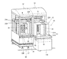
以下本発明の実施の形態を図面に基づいて説明する。図1は、本発明の第1の実施の形態に係る部品実装システム10を示すもので、当該部品実装システム10は、回路基板Bにはんだを印刷する印刷機モジュール11と、回路基板Bに電子部品(以下、単に部品と称す)を実装する複数の実装機モジュール12からなる作業モジュール13と、部品種の異なる多数の部品を保管する部品保管庫14と、これら作業モジュール13と部品保管庫14との間で部品を補給し、かつ部品を回収する複数の補給装置15を備えている。   Embodiments of the present invention will be described below with reference to the drawings. FIG. 1 shows a component mounting system 10 according to a first embodiment of the present invention. The component mounting system 10 includes a printer module 11 that prints solder on a circuit board B, and an electronic circuit on the circuit board B. A work module 13 comprising a plurality of mounter modules 12 for mounting parts (hereinafter simply referred to as parts), a parts storage 14 for storing a large number of parts of different parts, and these work modules 13 and parts storage 14 A plurality of replenishing devices 15 for replenishing parts and collecting parts are provided.

作業モジュール13を構成する印刷機モジュール11と複数の実装機モジュール12は、回路基板Bの搬送方向(X軸方向)に沿って配設されている。作業モジュール13は、X軸方向と直交するY軸方向に所定量離間されて互いに対向して2列並設されている。2列の作業モジュール13(以下、第1作業モジュール13A、第2作業モジュール13Bと称す)に沿って、各々複数の補給装置15が走行可能に設けられている。   The printing machine module 11 and the plurality of mounting machine modules 12 constituting the work module 13 are arranged along the conveyance direction (X-axis direction) of the circuit board B. The work modules 13 are arranged in parallel in two rows so as to be spaced apart from each other by a predetermined amount in the Y-axis direction orthogonal to the X-axis direction. A plurality of replenishing devices 15 are movably provided along two rows of work modules 13 (hereinafter referred to as first work module 13A and second work module 13B).

部品保管庫14は、第1および第2作業モジュール13A、13Bに対して、X軸方向に離間した位置に配設されている。部品保管庫14には、部品種の異なる部品を収容する複数のテープフィーダ34(図7(A)参照)や、部品種の異なる部品を収容する複数の部品トレイ37(図7(B)参照)が、図略の保管棚に整列して保管されており、オペレータによって必要な部品を収容したテープフィーダ34や部品トレイ37が補給装置15に補給されるようになっている。   The parts storage 14 is disposed at a position separated from the first and second work modules 13A and 13B in the X-axis direction. In the parts storage 14, a plurality of tape feeders 34 (see FIG. 7A) that accommodate parts having different parts types, and a plurality of part trays 37 (see FIG. 7B) that accommodate parts having different parts types. ) Are aligned and stored in a storage shelf (not shown), and a tape feeder 34 and a component tray 37 containing necessary components are supplied to the supply device 15 by an operator.

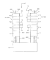
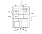
複数の実装機モジュール12は、図2に示すように、部品実装装置21と、部品供給装置22と、基板保持装置23と、基板搬送装置24を備えている。   As shown in FIG. 2, the plurality of mounting machine modules 12 includes a component mounting device 21, a component supply device 22, a substrate holding device 23, and a substrate transport device 24.

基板搬送装置24は、回路基板BをX軸方向に搬送する2列のベルトコンベヤ25A、25Bを有し、これらベルトコンベア25A、25Bに沿って回路基板Bを搬送し、基板保持装置23上に搬入するとともに、基板保持装置23から搬出するものである。基板保持装置23は、基板搬送装置24によって搬入された回路基板Bを下方から支持する基板支持装置と、回路基板Bを位置決めクランプするクランプ装置とを備えている。   The board transport device 24 has two rows of belt conveyors 25A and 25B that transport the circuit board B in the X-axis direction. The circuit board B is transported along the belt conveyors 25A and 25B and is placed on the board holding device 23. While carrying in, it carries out from the board | substrate holding | maintenance apparatus 23. FIG. The substrate holding device 23 includes a substrate support device that supports the circuit board B carried in by the substrate transfer device 24 from below, and a clamp device that positions and clamps the circuit board B.

部品実装装置21は、基板保持装置23の上方位置にY軸方向に移動可能に支持されたY軸スライド27と、Y軸スライド27上にX軸方向に移動可能に支持されたX軸スライド28と、X軸スライド28上に取付けられた実装ヘッド30とを備えている。実装ヘッド30には、図示してないが、部品を吸着保持する吸着ノズルが設けられている。Y軸スライド27およびX軸スライド28は、エンコーダ付サーボモータを駆動源とするX軸方向移動装置およびY軸方向移動装置によってそれぞれ移動され、実装ヘッド30をXY平面内の任意の位置へ移動できるようにしている。   The component mounting device 21 includes a Y-axis slide 27 supported above the board holding device 23 so as to be movable in the Y-axis direction, and an X-axis slide 28 supported on the Y-axis slide 27 so as to be movable in the X-axis direction. And a mounting head 30 mounted on the X-axis slide 28. Although not shown, the mounting head 30 is provided with a suction nozzle for sucking and holding components. The Y-axis slide 27 and the X-axis slide 28 are respectively moved by an X-axis direction moving device and a Y-axis direction moving device using a servo motor with an encoder as a drive source, and the mounting head 30 can be moved to an arbitrary position in the XY plane. I am doing so.

X軸スライド28上には、CCDカメラからなる基板撮像装置31が設けられており、基板撮像装置31は、基板保持装置23上に位置決めされた回路基板Bに設けられた基板位置基準マークおよび基板IDマークを撮像し、基板位置基準情報および基板ID情報を取得するようになっている。そして、基板撮像装置31によって取得された基板位置基準情報に基づいて、実装ヘッド30を回路基板Bに対してXY方向に位置補正するとともに、基板撮像装置31によって取得された基板ID情報に基づいて、部品の実装作業を制御するようになっている。   A substrate imaging device 31 composed of a CCD camera is provided on the X-axis slide 28, and the substrate imaging device 31 includes a substrate position reference mark and a substrate provided on the circuit board B positioned on the substrate holding device 23. An ID mark is imaged to obtain substrate position reference information and substrate ID information. And based on the board | substrate position reference information acquired by the board | substrate imaging device 31, while correcting the position of the mounting head 30 with respect to the circuit board B to XY direction, it is based on the board | substrate ID information acquired by the board | substrate imaging device 31. The component mounting operation is controlled.

32は、CCDカメラからなる部品撮像装置で、部品撮像装置32は、実装ヘッド30の吸着ノズルに吸着された部品を、部品供給装置22から回路基板B上に移動する途中で撮像する。そして、吸着ノズルに吸着された部品の吸着状態や、吸着ノズルの中心に対する部品の芯ずれ等を検出し、芯ずれ等に基づいて実装ヘッド30のXY方向の移動量等を補正し、部品が回路基板B上の定められた座標位置に定められた姿勢で実装できるようにしている。   Reference numeral 32 denotes a component imaging device including a CCD camera. The component imaging device 32 captures an image of the component sucked by the suction nozzle of the mounting head 30 while moving from the component supply device 22 onto the circuit board B. Then, the suction state of the component sucked by the suction nozzle, the misalignment of the component with respect to the center of the suction nozzle, and the like are detected, and the amount of movement of the mounting head 30 in the XY direction is corrected based on the misalignment, etc. The circuit board B can be mounted in a predetermined posture at a predetermined coordinate position.

部品供給装置22は、一例として、フィーダ型部品供給装置22Aと、トレイ型部品供給装置22Bからなっており、フィーダ型部品供給装置22Aは、フィーダ支持台33に着脱可能に装着された部品供給要素としての複数のテープフィーダ34を備え、これら複数のテープフィーダ34はX軸方向に並設されている。テープフィーダ34には、多数の部品を間隔を有して収容したテープが巻回され、テープをテープフィーダ34に内蔵された図略のモータにより駆動されるスプロケットによって間歇的に送り出すことにより、部品を所定の部品供給位置に順次供給できるようになっている。   The component supply device 22 includes, as an example, a feeder-type component supply device 22A and a tray-type component supply device 22B. The feeder-type component supply device 22A is a component supply element that is detachably attached to the feeder support base 33. The plurality of tape feeders 34 are arranged in parallel in the X-axis direction. The tape feeder 34 is wound with a tape containing a large number of parts at intervals, and the tapes are intermittently sent out by a sprocket driven by a motor (not shown) built in the tape feeder 34, thereby providing parts. Can be sequentially supplied to a predetermined component supply position.

なお、テープフィーダ34は、フィーダ支持台33に設けられたスロットに着脱可能に装着されるようになっており、テープフィーダ34がフィーダ支持台33に装着されると、図略のコネクタが接続されて、フィーダ支持台33からテープフィーダ34に電源が供給されるとともに、テープフィーダ34の制御部とフィーダ支持台33の制御部との間で必要な制御信号(部品要求信号、部品供給完了信号等)やテープフィーダ34のID等の管理情報が送信されるようになっている。   The tape feeder 34 is detachably attached to a slot provided in the feeder support base 33. When the tape feeder 34 is attached to the feeder support base 33, a connector (not shown) is connected. Then, power is supplied from the feeder support base 33 to the tape feeder 34, and necessary control signals (part request signal, part supply completion signal, etc.) between the control part of the tape feeder 34 and the control part of the feeder support base 33 are provided. ) And management information such as the ID of the tape feeder 34 are transmitted.

一方、トレイ型部品供給装置22Bは、図略のストッカを昇降可能に収納したハウジング35を備えている。ストッカには、多数の部品を収容保持した部品供給要素としての複数の部品トレイ37を上下方向に並設した複数のトレイ収容棚が設けられ、これらトレイ収納棚に収容された部品トレイ37は、ストッカよりY軸方向に引き出されて部品供給位置に位置決めされるようになっている。   On the other hand, the tray-type component supply device 22B includes a housing 35 in which a stocker (not shown) is accommodated so as to be movable up and down. The stocker is provided with a plurality of tray storage shelves in which a plurality of component trays 37 serving as component supply elements that store and hold a large number of components are arranged in the vertical direction, and the component trays 37 accommodated in these tray storage shelves are It is pulled out from the stocker in the Y-axis direction and positioned at the component supply position.

上記したフィーダ型部品供給装置22Aおよびトレイ型部品供給装置22Bは、ともに周知のものであり、フィーダ型部品供給装置22Aとして、例えば、本件と同じ出願人の出願に係る特開2012−104635号公報に記載された技術を利用でき、また、トレイ型部品供給装置22Bとして、例えば、本件と同じ出願人の出願に係る特開2009−147197号公報に記載された技術を利用できる。   Both the feeder-type component supply device 22A and the tray-type component supply device 22B described above are well known, and as the feeder-type component supply device 22A, for example, JP 2012-104635 A related to the application of the same applicant as this case. In addition, as the tray-type component supply device 22B, for example, the technique described in Japanese Patent Application Laid-Open No. 2009-147197 related to the same applicant's application as the present case can be used.

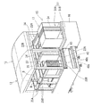
補給装置15は、図3および図4に示すように、各作業モジュール13A、13Bに沿って走行可能な走行台16と、走行台16上に搭載された補給ユニット17とを有している。補給装置15の走行台16を各作業モジュール13A、13Bに沿って走行させるために、第1および第2作業モジュール13Aを構成する印刷機モジュール11および複数の実装機モジュール12のそれぞれの前面には、断面コ字形をなす上部および下部ガイドレール40a、40bが、回路基板Bの搬送方向(X軸方向)に沿って取付けられている。   As shown in FIGS. 3 and 4, the replenishing device 15 includes a traveling platform 16 that can travel along the work modules 13 </ b> A and 13 </ b> B and a replenishment unit 17 mounted on the traveling platform 16. In order to cause the traveling table 16 of the replenishing device 15 to travel along the respective work modules 13A and 13B, the printing machine module 11 and the plurality of mounting machine modules 12 constituting the first and second work modules 13A are respectively provided on the front surfaces. The upper and lower guide rails 40a and 40b having a U-shaped cross section are attached along the conveying direction (X-axis direction) of the circuit board B.

これにより、印刷機モジュール11および複数の実装機モジュール12が回路基板Bの搬送方向に沿って一定間隔に配置されると、隣合う印刷機モジュール11および実装機モジュール12に取付けられた各上部ガイドレール40aおよび各下部ガイドレール40bが僅かな隙間を有して互いに接続され、回路基板Bの搬送方向に連続した直線状の第1ガイドレール機構41A、41B(図1参照)が構成される。   Thus, when the printing machine module 11 and the plurality of mounting machine modules 12 are arranged at regular intervals along the conveyance direction of the circuit board B, each upper guide attached to the adjacent printing machine module 11 and the mounting machine module 12 is provided. The rail 40a and the lower guide rails 40b are connected to each other with a slight gap, and linear first guide rail mechanisms 41A and 41B (see FIG. 1) continuous in the conveying direction of the circuit board B are configured.

第1ガイドレール機構41A、41Bの各一端と部品保管庫14との間にも、上記した第1ガイドレール機構41A、41Bに連続する第2ガイドレール機構42A、42Bが床面に設置されている。   The second guide rail mechanisms 42A and 42B that are continuous with the first guide rail mechanisms 41A and 41B described above are also installed on the floor between the respective one ends of the first guide rail mechanisms 41A and 41B and the parts storage 14. Yes.

また、第1ガイドレール機構41A、41Bと平行に第1噛合体としてのラック43が印刷機モジュール11および各実装機モジュール12の前面に取付けられている。ラック43は第2ガイドレール機構42A、42Bと平行に部品保管庫14内まで延在されている。   A rack 43 as a first meshing body is attached to the front surface of the printing machine module 11 and each mounting machine module 12 in parallel with the first guide rail mechanisms 41A and 41B. The rack 43 extends into the component storage 14 in parallel with the second guide rail mechanisms 42A and 42B.

補給装置15の各走行台16には、図3に示すように、上部ガイドレール40aの側面に転動可能に係合する上部フォロアローラ45aと、下部ガイドレール40bの底面に転動可能に係合する下部フォロアローラ45bとが、それぞれ回転可能に支持されている。これら上部および下部フォロアローラ45a、45bは、走行方向に間隔を有して複数設けられ、下部ガイドレール40bに係合する下部フォロアローラ45bによって専ら補給装置15の重量が支承され、上部ガイドレール40aに係合する上部フォロアローラ45aによって専ら走行台16のY方向の位置および姿勢が規制されている。   As shown in FIG. 3, each carriage 16 of the replenishing device 15 is associated with an upper follower roller 45a that engages with the side surface of the upper guide rail 40a and a bottom surface of the lower guide rail 40b. The lower follower rollers 45b to be joined are rotatably supported. A plurality of these upper and lower follower rollers 45a and 45b are provided at intervals in the traveling direction, and the weight of the replenishing device 15 is supported exclusively by the lower follower roller 45b engaged with the lower guide rail 40b, and the upper guide rail 40a. The position and posture of the traveling platform 16 in the Y direction are exclusively regulated by the upper follower roller 45a that engages with the upper follower roller 45a.

また、各走行台16には、ラック43に噛合う第2噛合体としてのピニオン47がそれぞれ回転可能に支持されており、ピニオン47を回転駆動するモータ48が走行台16に固定されている。モータ48には、後述する非接触伝送装置65によって作業モジュール13A、13B側から電力が供給され、回転制御される。この場合、第1噛合体43をラックに代えてチェーンとし、第2噛合体47をピニオン47に代えてスプロケットホイールとしてもよい。   Further, a pinion 47 as a second meshing body that meshes with the rack 43 is rotatably supported on each traveling platform 16, and a motor 48 that rotationally drives the pinion 47 is fixed to the traveling platform 16. Electric power is supplied to the motor 48 from the work modules 13A and 13B side by a non-contact transmission device 65, which will be described later, and its rotation is controlled. In this case, the first meshing body 43 may be replaced with a rack and a chain, and the second meshing body 47 may be replaced with a pinion 47 and a sprocket wheel.

これにより、ラック43に噛合うピニオン47がモータ48によって回転されると、走行台16が第1および第2ガイドレール機構41A、41B、42A、42Bに案内されて、部品保管庫14と各作業モジュール13との間で搬送されるようになっている。すなわち、モータ48は、走行台16を走行させるための走行用モータとして機能する。上記したガイドレール機構41A、41B、42A、42B、走行用モータ48、ラック43およびピニオン47等によって、補給装置15を搬送する搬送手段49を構成している。   Thus, when the pinion 47 meshing with the rack 43 is rotated by the motor 48, the traveling table 16 is guided to the first and second guide rail mechanisms 41A, 41B, 42A, 42B, and the parts storage 14 and each work It is transported between the module 13. That is, the motor 48 functions as a traveling motor for causing the traveling platform 16 to travel. The above-described guide rail mechanisms 41A, 41B, 42A, and 42B, the traveling motor 48, the rack 43, the pinion 47, and the like constitute a conveying means 49 that conveys the replenishing device 15.

補給装置15の走行台16上に搭載される補給ユニット17は、図4および図5に示すように、テープフィーダ34を保持するフィーダ補給ユニット51と、部品トレイ37を保持するトレイ補給ユニット52の2種類からなっており、複数の走行台16には、フィーダ補給ユニット51およびトレイ補給ユニット52のいずれか一方が搭載される。   As shown in FIGS. 4 and 5, the supply unit 17 mounted on the traveling table 16 of the supply device 15 includes a feeder supply unit 51 that holds the tape feeder 34 and a tray supply unit 52 that holds the component tray 37. There are two types, and one of the feeder supply unit 51 and the tray supply unit 52 is mounted on the plurality of traveling platforms 16.

フィーダ補給ユニット51は、複数のテープフィーダ34を収容可能で、これらテープフィーダ34を実装機モジュール12のフィーダ支持台33に補給するフィーダ補給部51Aと、複数のテープフィーダ34を収容可能で、実装機モジュール12のフィーダ支持台33よりテープフィーダ34を回収するフィーダ回収部51Bが、走行台16の走行方向に並設されている。   The feeder replenishment unit 51 can accommodate a plurality of tape feeders 34. The feeder replenishment unit 51A for replenishing the tape feeders 34 to the feeder support base 33 of the mounting machine module 12 and the plurality of tape feeders 34 can be accommodated. A feeder collection unit 51 </ b> B that collects the tape feeder 34 from the feeder support base 33 of the machine module 12 is arranged in parallel in the traveling direction of the traveling base 16.

フィーダ補給部51Aは、複数のテープフィーダ34をX軸方向に並設して保持し、これらテープフィーダ34をY軸方向に移動可能に保持している。フィーダ補給部51Aには、図6に示すように、各テープフィーダ34の下面に接触する送りローラ53を含むフィーダ送り機構が設けられ、送りローラ53を回転駆動することにより、テープフィーダ34をフィーダ補給部51AよりY軸方向に送り出して、実装機モジュール12のフィーダ型部品供給装置22Aの空きスロットに装着できるようにしている。   The feeder supply unit 51A holds a plurality of tape feeders 34 arranged in parallel in the X-axis direction, and holds these tape feeders 34 so as to be movable in the Y-axis direction. As shown in FIG. 6, the feeder replenishing portion 51 </ b> A is provided with a feeder feeding mechanism including a feeding roller 53 that contacts the lower surface of each tape feeder 34. By rotating the feeding roller 53, the tape feeder 34 is fed to the feeder. It is sent out in the Y-axis direction from the replenishing section 51A so that it can be mounted in an empty slot of the feeder-type component supply device 22A of the mounting machine module 12.

同様に、フィーダ回収部51Bにも、上記と同様なフィーダ送り機構が設けられ、このフィーダ送り機構により実装機モジュール12のフィーダ型部品供給装置22Aより回収すべきテープフィーダ34を引き出してフィーダ回収部51Bに回収できるようにしている。   Similarly, the feeder collecting unit 51B is also provided with a feeder feeding mechanism similar to that described above. With this feeder feeding mechanism, the tape feeder 34 to be collected is pulled out from the feeder-type component supply device 22A of the mounting machine module 12, and the feeder collecting unit 51B can be collected.

この場合、図示してないが、フィーダ型部品供給装置22Aのフィーダ支持台33には、テープフィーダ34をロック、アンロックするロック機構が設けられ、このロック機構のロック動作によって、テープフィーダ34をフィーダ支持台33に引き込んでロックするとともに、コネクタ接続するようになっている。逆に、ロック機構のアンロック動作によって、テープフィーダ34をフィーダ支持台33よりアンロックして押し出し、テープフィーダ34とフィーダ支持台33とのコネクタ接続を解除するようになっている。   In this case, although not shown, the feeder support base 33 of the feeder-type component supply device 22A is provided with a lock mechanism for locking and unlocking the tape feeder 34, and the tape feeder 34 is moved by the locking operation of the lock mechanism. The feeder support 33 is pulled in and locked, and is connected to a connector. On the contrary, the tape feeder 34 is unlocked and pushed out from the feeder support 33 by the unlocking operation of the lock mechanism, and the connector connection between the tape feeder 34 and the feeder support 33 is released.

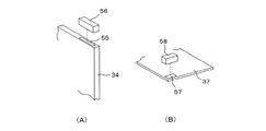
フィーダ補給部51Aには、図7(A)に示すように、フィーダ補給部51Aに収容されたテープフィーダ34に付与されたバーコード55を読み取るバーコードリーダ56が備えられ、部品保管庫14において必要とする部品を収納したテープフィーダ34が間違いなく補給されたか否かを照合できるようにしている。この場合、バーコード55に代えて、テープフィーダ34に2DコードもしくはRFIDを設け、この2DコードもしくはRFIDをフィーダ補給部51Aに設けたカメラあるいはRFIDリーダによって認識するようにしてもよい。   As shown in FIG. 7A, the feeder supply unit 51A is provided with a barcode reader 56 that reads the barcode 55 attached to the tape feeder 34 accommodated in the feeder supply unit 51A. It is possible to check whether or not the tape feeder 34 storing necessary parts has been replenished without fail. In this case, instead of the barcode 55, a 2D code or RFID may be provided in the tape feeder 34, and the 2D code or RFID may be recognized by a camera or an RFID reader provided in the feeder replenishing unit 51A.

一方、トレイ補給ユニット52は、複数の部品トレイ37を収容可能で、これら部品トレイ37を実装機モジュール12のハウジング35内のストッカに補給するトレイ補給部52Aと、複数の部品トレイ37を収容可能で、実装機モジュール12のハウジング35内のストッカより部品トレイ37を回収するトレイ回収部52Bが、走行台16の走行方向に並設されている。   On the other hand, the tray replenishment unit 52 can accommodate a plurality of component trays 37, and can accommodate a tray replenishment unit 52 </ b> A that replenishes these component trays 37 to the stocker in the housing 35 of the mounting machine module 12 and a plurality of component trays 37. Thus, a tray collection unit 52B that collects the component tray 37 from the stocker in the housing 35 of the mounting machine module 12 is provided in parallel in the traveling direction of the traveling table 16.

トレイ補給部52Aに収容された部品トレイ37は、図示してないトレイ送り機構によりY軸方向に送り出されて実装機モジュール12のトレイ型部品供給装置22Bのストッカの所定の収納棚に補給されるようになっている。同様に、トレイ回収部52Bには、図略のトレイ送り機構によって、実装機モジュール12のトレイ型部品供給装置22Bのストッカより、空になった部品トレイ37をY軸方向に引き出して回収するようになっている。   The component tray 37 accommodated in the tray replenishing section 52A is fed in the Y-axis direction by a tray feed mechanism (not shown) and replenished to a predetermined storage shelf of the stocker of the tray-type component supply device 22B of the mounting machine module 12. It is like that. Similarly, the tray collecting unit 52B uses the tray feed mechanism (not shown) to draw and collect the empty component tray 37 from the stocker of the tray-type component supply device 22B of the mounting machine module 12 in the Y-axis direction. It has become.

この際、複数の部品トレイ37を収容するトレイ補給部52Aを昇降可能とするか、あるいはトレイ型部品供給装置22Bのストッカの昇降運動を利用することによって、トレイ補給部52Aの各段に収容された複数の部品トレイ37をストッカの所定の収納棚に補給することができる。   At this time, the tray replenishing section 52A that accommodates the plurality of component trays 37 can be moved up or down, or the tray replenishing section 52A can be accommodated in each stage of the tray replenishing section 52A by using the up and down movement of the stocker of the tray type component supplying apparatus 22B. The plurality of component trays 37 can be replenished to a predetermined storage shelf of the stocker.

トレイ補給部52Aには、図7(B)に示すように、トレイ補給部52Aに収容された部品トレイ37に付与されたバーコード57を読み取るバーコードリーダ58が備えられ、部品保管庫14において必要とする部品を収納した部品トレイ37が間違いなく補給されたか否かが照合できるようにしている。   As shown in FIG. 7B, the tray supply unit 52A is provided with a barcode reader 58 that reads the barcode 57 attached to the component tray 37 accommodated in the tray supply unit 52A. It is possible to check whether or not the component tray 37 storing the necessary components is definitely supplied.

各作業モジュール13A、13Bと補給装置15との間で、給電および通信を非接触で行えるように、図3に示すように、印刷機モジュール11および複数の実装機モジュール12側に、X軸方向に延在した帯状の非接触伝送用ユニット63が、補給装置15側に、非接触伝送用ユニット63に対峙する非接触伝送用ヘッド64がそれぞれ取付けられている。これら非接触伝送用ユニット63および非接触伝送用ヘッド64によって非接触伝送装置65が構成され、非接触伝送装置65によって、作業モジュール13A、13B側から補給装置15側に電力を供給したり、作業モジュール13A、13B側と補給装置15側との間で必要な通信を行えるようにしている。   As shown in FIG. 3, the X-axis direction is arranged on the printing machine module 11 and the plurality of mounting machine modules 12 side so that power supply and communication can be performed in a non-contact manner between the respective work modules 13 </ b> A and 13 </ b> B and the replenishing device 15. A non-contact transmission unit 63 extending in the form of a non-contact transmission unit 63 facing the non-contact transmission unit 63 is attached to the supply device 15 side. These non-contact transmission unit 63 and non-contact transmission head 64 constitute a non-contact transmission device 65. The non-contact transmission device 65 supplies power from the work modules 13A and 13B to the replenishment device 15 or Necessary communication can be performed between the modules 13A and 13B and the replenishing device 15 side.

上記した第1の実施の形態においては、各補給装置15がそれぞれ複数の部品供給要素34、37を収容できるようになっているので、1台の補給装置15によって複数の実装機モジュール12に対して部品を補給することが可能である。また、第1および第2作業モジュール13A、13B毎にそれぞれ複数の補給装置15が備えられているので、複数の補給装置15によって複数の実装機モジュール12に同時に部品を補給することが可能である。   In the first embodiment described above, each replenishing device 15 can accommodate a plurality of component supply elements 34 and 37, so a single replenishing device 15 can support a plurality of mounting machine modules 12. Parts can be replenished. Further, since the plurality of replenishing devices 15 are provided for each of the first and second work modules 13A and 13B, it is possible to replenish components to the plurality of mounting machine modules 12 simultaneously by the plurality of replenishing devices 15. .

ただし、複数の補給装置15を部品保管庫14より出庫させる場合には、補給装置15の互いの干渉を防止するために、複数の補給装置15を部品保管庫14より同時に出庫させ、そして、複数の実装機モジュール12における部品補給作業が完了すると、複数の補給装置15を部品保管庫14に同時に帰還させるように制御することが好ましい。   However, when a plurality of replenishing devices 15 are delivered from the parts storage 14, the plurality of replenishing devices 15 are delivered simultaneously from the parts storage 14 in order to prevent the replenishing devices 15 from interfering with each other. When the component replenishment work in the mounting machine module 12 is completed, it is preferable to control so that the plurality of replenishment devices 15 are simultaneously returned to the component storage 14.

図8は、各実装機モジュール12を制御する制御装置70を示すもので、制御装置70は、CPU71,ROM72,RAM73およびそれらに接続された入出力インターフェース74を備えている。入出力インターフェース74には、部品実装装置21、部品供給装置22、基板保持装置23および基板搬送装置24を駆動する駆動回路75、基板撮像装置31および部品撮像装置32によって撮像された画像データを画像処理する画像処理装置76、バーコードリーダ56、58にて読み取られた情報を照合する照合部77等が接続されている。   FIG. 8 shows a control device 70 that controls each mounting machine module 12, and the control device 70 includes a CPU 71, a ROM 72, a RAM 73, and an input / output interface 74 connected thereto. The input / output interface 74 displays image data captured by the component mounting apparatus 21, the component supply apparatus 22, the board holding apparatus 23, and the board transport apparatus 24, the board imaging apparatus 31, and the component imaging apparatus 32. An image processing device 76 to be processed and a collation unit 77 for collating information read by the barcode readers 56 and 58 are connected.

制御装置70のROM72には、テープフィーダ34や部品トレイ37に収容された部品のシリアルID毎に、部品の型番,寸法,収容された部品個数等のデータが保存されている。これにより、バーコードリーダ56、58によって部品のシリアルIDが取得されると、部品の型番等を認識できるようになっている。   The ROM 72 of the control device 70 stores data such as the part model number, dimensions, and the number of parts accommodated for each serial ID of the parts accommodated in the tape feeder 34 and the part tray 37. Thereby, when the serial ID of the component is acquired by the barcode readers 56 and 58, the model number of the component can be recognized.

制御装置70には、作業モジュール13A、13Bおよび部品保管庫14を統合制御する管理コンピュータ80が接続されている。管理コンピュータ80は、第1および第2作業モジュール13A、13Bを統合制御する制御部81を備え、この制御部81に、補給装置15を搬送制御する搬送制御部82および補給装置15を補給制御する補給制御部83が接続されている。   A management computer 80 that integrally controls the work modules 13A and 13B and the parts storage 14 is connected to the control device 70. The management computer 80 includes a control unit 81 that integrally controls the first and second work modules 13A and 13B. The control unit 81 supplies and controls the transport control unit 82 that transports the replenishment device 15 and the replenishment device 15. A supply control unit 83 is connected.

次に上記した第1の実施の形態における部品補給動作について説明する。印刷機モジュール11および実装機モジュール12には、基板搬送装置24によって回路基板Bが順次搬送され、印刷機モジュール11においては、搬送された回路基板Bにはんだが印刷され、各実装機モジュール12においては、搬送された回路基板Bに部品実装装置21により予め定められたプログラムに従って部品が実装される。   Next, the component replenishing operation in the first embodiment will be described. The circuit board B is sequentially transferred to the printing machine module 11 and the mounting machine module 12 by the board transfer device 24. In the printing machine module 11, solder is printed on the transferred circuit board B. The components are mounted on the conveyed circuit board B according to a predetermined program by the component mounting apparatus 21.

各実装機モジュール12において、テープフィーダ34あるいは部品トレイ37より部品が取り出される毎に部品の残数が管理され、あるテープフィーダ34あるいはある部品トレイ37において部品切れが近づくと、実装機モジュール12の制御装置70より管理コンピュータ80に対し、部品の補給要求が指令される。   In each mounting machine module 12, the remaining number of parts is managed every time a part is taken out from the tape feeder 34 or the component tray 37, and when a part runs out in a certain tape feeder 34 or a certain component tray 37, The control device 70 instructs the management computer 80 to supply parts.

かかる部品の補給要求指令に基づいて、部品保管庫14内のオペレータに対し、部品保管庫14に待機している補給装置15のフィーダ補給ユニット51あるいはトレイ補給ユニット52に、部品補給が必要な部品種を収容したテープフィーダ34あるいは部品トレイ37を補給すべき指令が発せられる。   Based on such a component supply request command, an operator in the component storage unit 14 needs to supply components to the feeder supply unit 51 or the tray supply unit 52 of the supply device 15 waiting in the component storage unit 14. A command is issued to replenish the tape feeder 34 or the component tray 37 containing the product type.

例えば、ある実装機モジュール12において、部品種Aの部品を収容したテープフィーダ34が部品切れとなる場合には、フィーダ補給ユニット51のフィーダ補給部51Aに、部品種Aの部品を収容したテープフィーダ34がセットされる。   For example, in a certain mounting machine module 12, when the tape feeder 34 that accommodates a component type A component runs out, the tape feeder that accommodates the component type A component in the feeder replenishment unit 51 </ b> A of the feeder replenishment unit 51. 34 is set.

この際、フィーダ補給部51Aに所定のテープフィーダ34がセットされると、バーコードリーダ56によってテープフィーダ34のバーコード55が読み取られ、テープフィーダ34のシリアルIDが部品保管庫14に接続された管理コンピュータ80に送信される。管理コンピュータ80には、シリアルID毎に部品に関するデータが保存されているので、フィーダ補給部51Aにセットされたテープフィーダ34が、実装機モジュール12の制御装置70より指令された補給部品と同じ種類のものであるか否かが照合部77によって照合される。仮に、フィーダ補給部51Aにセットされた補給部品が間違ったものである場合には、部品保管庫14内のオペレータに対し照合エラーが報知される。   At this time, when a predetermined tape feeder 34 is set in the feeder replenishing portion 51A, the barcode 55 of the tape feeder 34 is read by the barcode reader 56, and the serial ID of the tape feeder 34 is connected to the parts storage 14. It is transmitted to the management computer 80. Since the management computer 80 stores data related to parts for each serial ID, the tape feeder 34 set in the feeder replenishing section 51A is the same type as the replenished parts instructed by the control device 70 of the mounting machine module 12. It is collated by the collation unit 77 whether or not it is. If the supply component set in the feeder supply unit 51A is wrong, an operator in the component storage 14 is notified of a verification error.

補給すべき部品種Aの部品を収容したテープフィーダ34がフィーダ補給ユニット51にセットされると、補給装置15の走行台16に設けられた走行用モータ48が駆動される。走行用モータ48の駆動により、ラック43に噛合うピニオン47が回転駆動され、これにより、走行台16は第2ガイドレール機構42Aおよび第1ガイドレール41Aに案内支持されて、部品保管庫14より、部品補給が必要な実装機モジュール12に向けて出庫される。   When the tape feeder 34 containing the parts of the part type A to be replenished is set in the feeder replenishment unit 51, the traveling motor 48 provided on the traveling platform 16 of the replenishing device 15 is driven. By driving the traveling motor 48, the pinion 47 that meshes with the rack 43 is rotationally driven, whereby the traveling table 16 is guided and supported by the second guide rail mechanism 42 </ b> A and the first guide rail 41 </ b> A from the parts storage 14. The product is delivered toward the mounting machine module 12 that requires component replenishment.

この際、非接触伝送装置65を介して補給装置15と実装機モジュール12との間で非接触で情報が伝送され、補給装置15が部品補給の必要な実装機モジュール12に走行制御される。   At this time, information is transmitted in a non-contact manner between the replenishing device 15 and the mounting machine module 12 via the non-contact transmission device 65, and the replenishing device 15 is controlled to travel to the mounting machine module 12 that requires component replenishment.

補給装置15が所定の実装機モジュール12まで走行されると、走行用モータ48が停止され、補給装置15が実装機モジュール12に対して定められた位置に位置決めされる。その状態で、フィーダ補給ユニット51のフィーダ補給部51Aのフィーダ送り機構の送りローラ53が正転駆動され、補給部品を収容したテープフィーダ34がフィーダ補給部51Aよりフィーダ型部品供給装置22Aのフィーダ支持台33の空のスロットに向けて送り出される。   When the replenishing device 15 travels to a predetermined mounting machine module 12, the traveling motor 48 is stopped and the replenishing device 15 is positioned at a predetermined position with respect to the mounting machine module 12. In this state, the feed roller 53 of the feeder feeding mechanism of the feeder replenishing unit 51A of the feeder replenishing unit 51 is driven to rotate forward, and the tape feeder 34 containing the replenishing parts is supported by the feeder of the feeder-type component feeder 22A from the feeder replenishing unit 51A. It is sent out toward the empty slot of the table 33.

テープフィーダ34が空のスロットの所定位置まで送り出されると、図略のロック装置によってテープフィーダ34がフィーダ支持台33に装着されるとともに、テープフィーダ34とフィーダ支持台33とがコネクタ接続される。   When the tape feeder 34 is sent to a predetermined position in an empty slot, the tape feeder 34 is mounted on the feeder support base 33 by a lock device (not shown), and the tape feeder 34 and the feeder support base 33 are connected by a connector.

補給部品を収容したテープフィーダ34がフィーダ支持台33に装着されると、続いて、走行用モータ48が所定量回転され、走行台16がX軸方向に所定量移動される。これにより、フィーダ補給ユニット51のフィーダ回収部51Bが、部品切れとなったテープフィーダ34に対応する位置に位置決めされる。その状態で、テープフィーダ34が、図略のロック装置のアンロックにより、フィーダ支持台33よりアンロックされ、次いで、フィーダ補給ユニット51のフィーダ送り機構の送りローラ(53)が逆転されてテープフィーダ34がフィーダ支持台33のスロットよりフィーダ補給ユニット51のフィーダ回収部51Bに回収される。   When the tape feeder 34 containing the supply parts is mounted on the feeder support base 33, the traveling motor 48 is rotated by a predetermined amount, and the traveling base 16 is moved by a predetermined amount in the X-axis direction. Thereby, the feeder collection | recovery part 51B of the feeder replenishment unit 51 is positioned in the position corresponding to the tape feeder 34 from which components were cut. In this state, the tape feeder 34 is unlocked from the feeder support base 33 by unlocking a locking device (not shown), and then the feed roller (53) of the feeder feeding mechanism of the feeder replenishing unit 51 is reversely rotated to reverse the tape feeder. 34 is recovered from the slot of the feeder support 33 to the feeder recovery part 51B of the feeder supply unit 51.

この場合、まず、部品切れを生じたテープフィーダ34を、フィーダ補給ユニット51のフィーダ回収部51Bに回収し、しかる後、その空いたスロットに、補給すべきテープフィーダ34を補給するようにしてもよい。   In this case, first, the tape feeder 34 in which the parts are cut out is collected in the feeder collection unit 51B of the feeder supply unit 51, and then the tape feeder 34 to be supplied is supplied to the empty slot. Good.

このように、部品切れとなった部品種Aの部品を、部品保管庫14より実装機モジュール12に自動的に補給することにより、部品供給位置を、新たに装着されたテープフィーダ34の供給位置に切替えるだけで、実装作業を中断することなく、生産を継続して行うことが可能となり、省人化および自動化が可能となる。   In this way, by automatically replenishing the mounter module 12 with the component type A component that has run out of components, the component supply position is changed to the supply position of the newly mounted tape feeder 34. By simply switching to, production can be continued without interrupting the mounting operation, and labor saving and automation can be achieved.

テープフィーダ34の補給および回収を終了した補給装置15は、部品保管庫14に帰還され、部品保管庫14において、フィーダ補給ユニット51のフィーダ回収部51Bより空のテープフィーダ34が取外される。   The replenishing device 15 that has finished replenishing and collecting the tape feeder 34 is returned to the parts storage 14, and the empty tape feeder 34 is removed from the feeder collection unit 51 </ b> B of the feeder replenishment unit 51 in the parts storage 14.

この場合、複数の実装機モジュール12において、部品の補給が必要になった場合には、フィーダ補給ユニット51のフィーダ補給部51Aに、複数の実装機モジュール12で必要な部品種の部品を収容した複数のテープフィーダ34を搭載し、補給装置15を複数の実装機モジュール12で順次停止させながら、上記したように、テープフィーダ34の補給および回収を行うことも可能である。   In this case, when it is necessary to replenish components in the plurality of mounting machine modules 12, parts of the component types necessary for the plurality of mounting machine modules 12 are accommodated in the feeder replenishing unit 51 </ b> A of the feeder replenishing unit 51. It is also possible to supply and collect the tape feeder 34 as described above while mounting a plurality of tape feeders 34 and sequentially stopping the replenishing device 15 by the plurality of mounting machine modules 12.

なお、実装機モジュール12に、部品トレイ37を補給する場合も、上記したテープフィーダ34の補給動作と同様に行われる。すなわち、実装機モジュール12の制御装置70より管理コンピュータ80に対し、ある部品トレイ37に収容された部品種Bの部品の補給が指令されると、部品保管庫14に待機中の補給装置15上のトレイ補給ユニット52のトレイ補給部52Aに、部品種Bの部品を収容した部品トレイ37がセットされ、部品補給の必要な実装機モジュール12まで搬送される。   Note that when the component tray 37 is replenished to the mounting machine module 12, the same operation as the replenishment operation of the tape feeder 34 is performed. That is, when the control device 70 of the mounting machine module 12 instructs the management computer 80 to replenish the component type B contained in a certain component tray 37, the component storage unit 14 is in the standby replenishing device 15. A component tray 37 containing components of component type B is set in the tray replenishing portion 52A of the tray replenishing unit 52 and conveyed to the mounting machine module 12 that needs component replenishment.

図9は、本発明の第2の実施の形態を示すもので、第1の実施の形態と異なる点は、補給装置15を無人搬送台車116からなる搬送手段によって、部品保管庫14と各作業モジュール13との各間で搬送できるようにしたことである。なお、第1の実施の形態で述べたと同一の構成部品については同一の参照番号を付し、説明を省略する。   FIG. 9 shows a second embodiment of the present invention, which is different from the first embodiment in that the replenishment device 15 is moved to the parts storage 14 and each work by a transport means including an unmanned transport carriage 116. This means that it can be transported between each module 13. Note that the same components as those described in the first embodiment are denoted by the same reference numerals, and description thereof is omitted.

第2の実施の形態においては、第1の実施の形態で述べた各作業モジュール13A、13Bの前面側の床面上をX軸方向に沿って走行可能に複数の無人搬送台車116が設けられ、複数の無人搬送台車116は、床面に埋設したガイドライン90の磁気誘導作用によって、部品保管庫14と作業モジュール13との各間で搬送可能である。なお、ガイドライン90は床面に埋設する他、作業モジュール13A、13Bの前面に設けてもよい。   In the second embodiment, a plurality of automatic guided vehicles 116 are provided so as to be able to travel along the X-axis direction on the floor surface on the front side of each work module 13A, 13B described in the first embodiment. The plurality of automatic guided vehicles 116 can be transported between the parts storage 14 and the work module 13 by the magnetic induction action of the guideline 90 embedded in the floor surface. The guideline 90 may be provided on the front surface of the work modules 13A and 13B, in addition to being embedded in the floor surface.

複数の無人搬送台車116上には、図9に示すフィーダ補給ユニット51、あるいは図示省略したトレイ補給ユニット52(図5参照)をX軸方向に移動可能に載置する移動台91が、図略のガイド機構によってX軸方向にそれぞれ移動可能に案内支持されている。移動台91は、図10に示すように、モータ92によって駆動されるボールねじ93と、これに螺合する送りナット94からなる移動装置95によってX軸方向に移動できるようになっている。   On a plurality of automatic guided carriages 116, a moving table 91 on which a feeder supply unit 51 shown in FIG. 9 or a tray supply unit 52 (not shown) is mounted so as to be movable in the X-axis direction is not shown. These guide mechanisms are guided and supported so as to be movable in the X-axis direction. As shown in FIG. 10, the movable table 91 can be moved in the X-axis direction by a moving device 95 including a ball screw 93 driven by a motor 92 and a feed nut 94 screwed to the ball screw 93.

また、実装機モジュール12に対して無人搬送台車116を正確に位置決め停止することが難しいため、実装機モジュール12の前面には、図11に示すように、位置決め手段を構成する一対の位置決めピン97がX軸方向に離間した位置に進退可能に設けられ、無人搬送台車116が実装機モジュール12に対応する位置に図略のセンサ等の検出信号に基づいて停止されると、一対の位置決めピン97が前進されて無人搬送台車116の停止位置を補正する。これによって、無人搬送台車116を実装機モジュール12に対して正確な位置に位置決めできるようにしている。   Further, since it is difficult to accurately position and stop the automatic guided carriage 116 with respect to the mounting machine module 12, a pair of positioning pins 97 constituting positioning means are provided on the front surface of the mounting machine module 12 as shown in FIG. When the automatic guided carriage 116 is stopped at a position corresponding to the mounting machine module 12 based on a detection signal from an unillustrated sensor or the like, a pair of positioning pins 97 is provided. Is advanced to correct the stop position of the automatic guided vehicle 116. As a result, the automatic guided vehicle 116 can be positioned at an accurate position with respect to the mounting machine module 12.

この場合、無人搬送台車116に、実装機モジュール12の前面に当接可能なガイドローラ98を設けてもよく、ガイドローラ98を常に実装機モジュール12の前面に当接させながら無人搬送台車116を走行させることにより、実装機モジュール12と無人搬送台車116との隙間を一定に保持させることが可能となる。   In this case, a guide roller 98 that can come into contact with the front surface of the mounting machine module 12 may be provided on the automatic transport cart 116, and the unmanned transport cart 116 is kept in contact with the front surface of the mounting machine module 12 at all times. By running, the gap between the mounting machine module 12 and the automatic guided vehicle 116 can be kept constant.

無人搬送台車116には、図示してないが、走行駆動源としてのモータが搭載されており、このモータに非接触伝送装置65によって作業モジュール13A、13B側から電力が供給され、無人搬送台車116が搬送制御される。この場合、無人搬送台車116にモータ電源としてのバッテリを内蔵させ、このバッテリによって無人搬送台車116を搬送制御するとともに、各実装機モジュール12において部品が補給されている間に、非接触伝送装置65によって非接触給電された電力をバッテリに蓄電するようにしてもよい。   Although not shown, the automatic guided carriage 116 is equipped with a motor as a travel drive source. Electric power is supplied to the motor from the work modules 13A and 13B by the non-contact transmission device 65, and the automatic guided carriage 116 is supplied. Is controlled. In this case, a battery as a motor power supply is built in the automatic guided vehicle 116, and the automatic transfer cart 116 is controlled to be transported by this battery, and the non-contact transmission device 65 is used while parts are being replenished in each mounting machine module 12. The electric power supplied in a non-contact manner may be stored in the battery.

かかる第2の実施の形態においては、補給装置15を無人搬送台車116によって、部品補給が必要な実装機モジュール12に対応する位置まで搬送し、図略のセンサ等を用いて位置決め停止する。しかる後、実装機モジュール12の前面に設けた一対の位置決めピン97を前進させて、無人搬送台車116の停止位置をX軸方向に微調整し、無人搬送台車116を実装機モジュール12に対して定められた位置に正確な位置決めする。   In the second embodiment, the replenishing device 15 is transported by the unmanned transport carriage 116 to a position corresponding to the mounting machine module 12 that requires component replenishment, and positioning is stopped using a sensor (not shown). Thereafter, the pair of positioning pins 97 provided on the front surface of the mounting machine module 12 are advanced to finely adjust the stop position of the automatic guided carriage 116 in the X-axis direction. Accurate positioning at a defined position.

この際、無人搬送台車116上に図9に示すような複数のテープフィーダ34を収容したフィーダ補給ユニット51が搭載されている場合には、移動台91を移動装置95によってX軸方向に移動して、フィーダ補給部51Aに収容された所定のテープフィーダ(補給すべきテープフィーダ)34を、実装機モジュール12のフィーダ型部品供給装置22Aの空のスロットに一致する位置に位置決めし、図略のフィーダ送り機構によりテープフィーダ34を空のスロットに装着する。次いで、移動台91を移動装置95によってX軸方向に移動して、フィーダ回収部51Bの空の収容部を、フィーダ型部品供給装置22Aより回収すべき所定のテープフィーダ(部品切れのテープフィーダ)34に一致する位置に位置決めし、図略のフィーダ送り機構によりテープフィーダ34を引き出してフィーダ回収部51Bに回収する。   At this time, when the feeder replenishment unit 51 containing a plurality of tape feeders 34 as shown in FIG. 9 is mounted on the automatic guided carriage 116, the moving table 91 is moved in the X-axis direction by the moving device 95. Then, a predetermined tape feeder (tape feeder to be replenished) 34 accommodated in the feeder replenishing section 51A is positioned at a position corresponding to an empty slot of the feeder-type component supply device 22A of the mounting machine module 12, and is not shown. The tape feeder 34 is mounted in an empty slot by the feeder feeding mechanism. Next, the movable table 91 is moved in the X-axis direction by the moving device 95, and a predetermined tape feeder to be recovered from the feeder-type component supply device 22A in the empty storage portion of the feeder recovery portion 51B (tape feeder with a component cut). 34, the tape feeder 34 is pulled out by a feeder feed mechanism (not shown) and collected in the feeder collection unit 51B.

なお、図示省略したが、別の無人搬送台車116には、図5に示したと同様なトレイ補給ユニット52が上記した移動台91上に支持され、このトレイ補給ユニット52によって、部品トレイ37が実装機モジュール12のトレイ型部品供給装置22Bとの間で補給および回収される。   Although not shown in the figure, another automatic guided carriage 116 supports a tray supply unit 52 similar to that shown in FIG. 5 on the above-described moving table 91, and the component tray 37 is mounted by the tray supply unit 52. The machine module 12 is replenished and collected with the tray-type component supply device 22B.

図12は、本発明の第3の実施の形態を示すもので、補給装置15の無人搬送台車116を磁気誘導する第1作業モジュール13A側のガイドライン90Aと、第2作業モジュール13B側のガイドライン90Bの各端部を互いに接続して、無端状のガイドライン90Cを構成したものである。かかる第3の実施の形態においては、部品保管庫14から出庫した補給装置15を、第1作業モジュール13Aおよび第2作業モジュール13Bを経由して部品保管庫14に帰還させることが可能となる。なお、第1の実施の形態で述べたと同一の構成部品については同一の参照番号を付し、説明を省略する。   FIG. 12 shows a third embodiment of the present invention. The guideline 90A on the first work module 13A side for magnetically guiding the automatic guided carriage 116 of the replenishing device 15 and the guideline 90B on the second work module 13B side are shown. These end portions are connected to each other to constitute an endless guideline 90C. In the third embodiment, the replenishing device 15 delivered from the parts storage 14 can be returned to the parts storage 14 via the first work module 13A and the second work module 13B. Note that the same components as those described in the first embodiment are denoted by the same reference numerals, and description thereof is omitted.

従って、第3の実施の形態によれば、補給装置15が複数存在する場合であっても、部品保管庫14より出庫した補給装置15と、部品保管庫14に帰還する補給装置15が干渉しあう恐れがないので、第1の実施の形態で述べたように、複数の補給装置15を部品保管庫14から同時に出庫させる必要がなく、部品補給の要求に応じて補給装置15を順次出庫させることが可能となる。しかも、1つの補給装置15に、第1および第2作業モジュール13A、13Bの各実装機モジュール12で補給すべき部品を収容した複数の部品供給要素34、37搭載して、第1および第2作業モジュール13A、13Bの各実装機モジュール12に順次部品を補給することも可能となり、部品補給の効率を高めることができる。   Therefore, according to the third embodiment, even when there are a plurality of replenishing devices 15, the replenishing device 15 delivered from the parts storage 14 interferes with the replenishing device 15 returning to the parts storage 14. Since there is no fear, as described in the first embodiment, it is not necessary to release a plurality of replenishing devices 15 from the component storage 14 at the same time, and the replenishing devices 15 are sequentially delivered in response to a request for replenishment of components. It becomes possible. In addition, a plurality of component supply elements 34 and 37 that contain components to be replenished by the mounting machine modules 12 of the first and second work modules 13A and 13B are mounted on one replenishing device 15, and the first and second components are mounted. It is also possible to sequentially supply components to the mounting machine modules 12 of the work modules 13A and 13B, and the efficiency of component supply can be increased.

なお、部品保管庫14から出庫した補給装置15を、第1作業モジュール13Aおよび第2作業モジュール13Bを経由して部品保管庫14に帰還させる方式は、無人搬送台車116に限らず、第1の実施の形態で述べた走行台16を走行させるものにも適用可能である。この場合には、2列の第1ガイドレール機構54A、54Bの端部を円弧状のガイドレール機構によって互いに連結するとともに、この円弧状のガイドレール機構部分に、ピニオン47に噛合う円弧状のギヤ部をラック43に連接するように設けることによって可能となる。   The method of returning the replenishing device 15 delivered from the parts storage 14 to the parts storage 14 via the first work module 13A and the second work module 13B is not limited to the automatic guided carriage 116, but the first The present invention is also applicable to a vehicle that travels on the traveling platform 16 described in the embodiment. In this case, the ends of the two rows of the first guide rail mechanisms 54A and 54B are connected to each other by the arcuate guide rail mechanism, and the arcuate guide rail mechanism portion is engaged with the arcuate pinion 47. This is possible by providing the gear portion so as to be connected to the rack 43.

図13は、第4の実施の形態を示すもので、無人搬送台車116を用いながら、無人搬送台車116を、第1の実施の形態で述べた上部および下部ガイドレール40a、40bによってガイドするようにしたものであり、その他の点については第1の実施の形態で述べたものと同じである。これによれば、各実装機モジュール12に位置決めされる無人搬送台車116のY軸方向の位置精度を高めることができる。   FIG. 13 shows a fourth embodiment. The automatic guided vehicle 116 is guided by the upper and lower guide rails 40a and 40b described in the first exemplary embodiment while the automatic guided vehicle 116 is used. The other points are the same as those described in the first embodiment. According to this, the position accuracy in the Y-axis direction of the automatic guided vehicle 116 positioned on each mounting machine module 12 can be improved.

上記した実施の形態によれば、多数の部品を収容した複数の部品供給要素34、37を保管する部品保管庫14と、部品保管庫14と複数の実装機モジュール12との間で走行可能で、部品供給要素34、37を支持して部品供給要素34,37を、複数の実装機モジュール12に補給し、かつ複数の実装機モジュール12より回収する補給装置15と、補給装置15を部品保管庫14と複数の実装機モジュール12との間で搬送する搬送手段49と、複数の実装機モジュール12と補給装置15との間で信号を非接触で伝送する非接触伝送装置65と、実装機モジュール12と補給装置15との間で補給される部品供給要素34,37のIDを読取って照合する照合部77とを備えている。   According to the above-described embodiment, it is possible to travel between the component storage 14 that stores the plurality of component supply elements 34 and 37 that contain a large number of components, and between the component storage 14 and the plurality of mounting machine modules 12. The component supply elements 34 and 37 are supported and the component supply elements 34 and 37 are replenished to the plurality of mounting machine modules 12 and are collected from the plurality of mounting machine modules 12. Conveying means 49 for conveying between the storage 14 and the plurality of mounting machine modules 12, a non-contact transmission device 65 for transmitting signals in a non-contact manner between the plurality of mounting machine modules 12 and the replenishing device 15, and a mounting machine A collation unit 77 that reads and collates the IDs of the component supply elements 34 and 37 to be replenished between the module 12 and the replenishing device 15 is provided.

上記した構成により、実装機モジュール12の部品供給装置22において部品切れを生じても、部品切れを起こした部品供給要素34、37を支持して部品保管庫14から実装機モジュール12まで走行する補給装置15により、必要な部品を自動で効率的に補給することができ、省人化および自動化が可能となる。   With the above-described configuration, even if the component supply device 22 of the mounting machine module 12 runs out of parts, the replenishment that travels from the component storage 14 to the mounting machine module 12 while supporting the component supply elements 34 and 37 that have caused the parts cut. The device 15 can automatically and efficiently replenish necessary parts, and can save labor and automation.

これによって、オペレータは部品保管庫14内で補給装置15に必要な部品供給要素34、37を補給するだけでよく、また、部品保管庫14における補給装置15への部品供給要素34、37の補給を自動化することで、オペレータなしで部品補給が可能となる。   As a result, the operator only needs to replenish the component supply elements 34 and 37 necessary for the replenishment device 15 in the component storage 14, and replenish the component supply elements 34 and 37 to the replenishment device 15 in the component storage 14. By automating, parts can be replenished without an operator.

上記した実施の形態によれば、補給装置15は、複数の部品供給要素34、37を支持できるので、複数の部品供給要素34、37を支持した補給装置15により、実装機モジュール12において複数の部品供給要素34、37を補給することが可能である。   According to the above-described embodiment, the replenishment device 15 can support the plurality of component supply elements 34 and 37, so that the replenishment device 15 that supports the plurality of component supply elements 34 and 37 allows a plurality of components to be mounted in the mounting machine module 12. It is possible to supply the component supply elements 34, 37.

上記した実施の形態によれば、補給装置15は、部品種の異なる部品を収容した各種の部品供給要素34、37を支持できるので、部品種の異なる部品を収容した各種の部品供給要素34、37を支持した補給装置15により、複数の実装機モジュール12において部品種の異なる部品を収容した各種の部品供給要素34、37を補給することが可能である。   According to the above-described embodiment, the replenishing device 15 can support the various component supply elements 34 and 37 that accommodate components of different component types, and thus the various component supply elements 34 that accommodate components of different component types, By the replenishing device 15 that supports 37, it is possible to replenish various component supply elements 34 and 37 that accommodate components of different component types in the plurality of mounting machine modules 12.

上記した実施の形態によれば、搬送手段49は、複数の実装機モジュールの前面側に設けられたガイドレール40a、40bおよびガイドレール40a、40bに平行なラック(チェーン)43と、補給装置15側に設けられ、ガイドレール40a、40bに係合するフォロアローラ45a、45b、ラック43に噛合うピニオン(スプロケットホイール)47およびピニオン47を回転する走行用モータ48によって構成されている。   According to the above-described embodiment, the transport means 49 includes the guide rails 40a and 40b and the rack (chain) 43 parallel to the guide rails 40a and 40b provided on the front surface side of the plurality of mounting machine modules, and the replenishing device 15. And a follower roller 45a, 45b that engages with the guide rails 40a, 40b, a pinion (sprocket wheel) 47 that meshes with the rack 43, and a traveling motor 48 that rotates the pinion 47.

これにより、走行用モータ48の回転によって、ピニオン47およびラック43を介して補給装置15を搬送することができ、しかも、走行用モータ48の回転停止精度によって補給装置15を実装機モジュール12に対して正確な位置に位置決めすることができる。   As a result, the replenishing device 15 can be transported through the pinion 47 and the rack 43 by the rotation of the traveling motor 48, and the replenishing device 15 can be moved to the mounting machine module 12 by the rotational stop accuracy of the traveling motor 48. Can be positioned at an accurate position.

上記した実施の形態によれば、非接触伝送装置65は、複数の実装機モジュール12より補給装置15に非接触で給電を行うことができるので、実装機モジュール12側より補給装置15側のモータ等に適宜電力を供給することが可能となる。   According to the above-described embodiment, the non-contact transmission device 65 can supply power to the replenishing device 15 from the plurality of mounting machine modules 12 in a non-contact manner, and therefore the motor on the replenishing device 15 side from the mounting machine module 12 side. Thus, it is possible to supply power appropriately.

上記した実施の形態によれば、補給装置15は、複数の実装機モジュール12に沿って敷設されたガイドライン90に誘導されて床面上を走行可能な無人搬送台車116と、無人搬送台車116上に搭載され部品供給要素34,37を補給および回収可能に支持した補給ユニット17によって構成したので、実装機モジュール12を大幅に改造することなく、無人搬送台車およびガイドライン90を配設することによって、部品補給の自動化が可能な部品実装システムを容易に構築することができる。   According to the above-described embodiment, the replenishing device 15 is guided by the guideline 90 laid along the plurality of mounting machine modules 12 and can run on the floor surface. The component supply elements 34 and 37 mounted on the support unit 17 are configured to replenish and support the component supply elements 34 and 37 so that the mounting machine module 12 is not significantly modified. A component mounting system capable of automating component replenishment can be easily constructed.

上記した実施の形態によれば、無人搬送台車116と補給ユニット17の間に、無人搬送台車116に対して補給ユニット17を無人搬送台車116の走行方向に移動する移動台91を設けたので、実装機モジュール12に対して補給ユニット17のX軸方向位置を変更する場合でも、移動台91の移動によって容易に対応することができる。   According to the above-described embodiment, since the movable table 91 for moving the supply unit 17 in the traveling direction of the automatic guided vehicle 116 is provided between the automatic guided vehicle 116 and the supply unit 17, Even when the position of the replenishment unit 17 in the X-axis direction is changed with respect to the mounting machine module 12, it can be easily handled by the movement of the movable table 91.

上記した実施の形態によれば、複数の実装機モジュール12の前面に、無人搬送台車116を走行方向に位置決めする位置決め手段(位置決めピン97)を設けたので、実装機モジュール12に対応する位置に停止された無人搬送台車116の停止位置を、位置決め手段によって補正することができる。これにより、実装機モジュール12に対して正確に位置決め停止することが難しい無人搬送台車116においても、実装機モジュール12に対して正確な位置に位置決めすることが容易に可能となる。   According to the above-described embodiment, since the positioning means (positioning pin 97) for positioning the automatic guided carriage 116 in the traveling direction is provided on the front surface of the plurality of mounting machine modules 12, the positioning means 97 is positioned at a position corresponding to the mounting machine module 12. The stop position of the stopped automatic guided vehicle 116 can be corrected by the positioning means. Thereby, even in the automatic guided vehicle 116 that is difficult to accurately stop positioning with respect to the mounting machine module 12, it is possible to easily position the mounting machine module 12 at an accurate position.

上記した実施の形態によれば、複数の実装機モジュール12の前面に、ガイドレール40a、40bをそれぞれ設け、これらガイドレール40a、40bに係合するフォロアローラ45a、45bを無人搬送台車116に支持したので、床面上を走行する無人搬送台車116がガイドレール40a、40bにガイドされ、実装機モジュール12に位置決めされる無人搬送台車116の走行方向と直交する方向の位置精度を高めることができる。   According to the above-described embodiment, the guide rails 40a and 40b are provided on the front surface of the plurality of mounting machine modules 12, respectively, and the follower rollers 45a and 45b engaged with the guide rails 40a and 40b are supported by the automatic guided vehicle 116. Therefore, the unmanned conveyance cart 116 traveling on the floor surface is guided by the guide rails 40a and 40b, and the positional accuracy in the direction orthogonal to the traveling direction of the unmanned conveyance cart 116 positioned on the mounting machine module 12 can be improved. .

上記した実施の形態においては、補給ユニット17に複数の部品供給要素(テープフィーダ34あるいは部品トレイ37)を保持できるようにしたが、補給ユニット17に単一の部品供給要素を保持してもよい。   In the above-described embodiment, a plurality of component supply elements (tape feeder 34 or component tray 37) can be held in the supply unit 17, but a single component supply element may be held in the supply unit 17. .

また、上記した実施の形態においては、2列の作業モジュール13A、13BをX軸方向に間隔を有して配置した例について述べたが、作業モジュールは3列以上あるいは単列とすることもできる。   In the above-described embodiment, an example in which two rows of work modules 13A and 13B are arranged with an interval in the X-axis direction has been described. However, the work modules may be three rows or more or a single row. .

以上、本発明の実施の形態について説明したが、本発明は上記した実施の形態に限定されることなく、特許請求の範囲に記載した本発明の主旨を逸脱しない範囲内で種々の変形が可能である。   Although the embodiments of the present invention have been described above, the present invention is not limited to the above-described embodiments, and various modifications can be made without departing from the spirit of the present invention described in the claims. It is.

本発明に係る部品実装システムは、部品保管庫と複数の実装機モジュールとの間で走行可能な補給装置によって部品を補給するものに用いるのに適している。   The component mounting system according to the present invention is suitable for being used for replenishing components by a replenishing device that can travel between a component storage and a plurality of mounting machine modules.

10…部品実装システム、12…実装機モジュール、13…作業モジュール、14…部品保管庫、15…補給装置、16…走行台、17…補給ユニット、34…テープフィーダ、37…トレイ、41A、41B…ガイドレール機構、43…第1噛合体、47…第2噛合体、48…走行用モータ、49…搬送手段、51…フィーダ補給ユニット、52…トレイ補給ユニット、65…非接触伝送装置、70…制御装置、77…照合部、80…管理コンピュータ。   DESCRIPTION OF SYMBOLS 10 ... Component mounting system, 12 ... Mounting machine module, 13 ... Work module, 14 ... Parts storage, 15 ... Replenishment apparatus, 16 ... Running stand, 17 ... Replenishment unit, 34 ... Tape feeder, 37 ... Tray, 41A, 41B ... guide rail mechanism, 43 ... first meshing body, 47 ... second meshing body, 48 ... traveling motor, 49 ... conveying means, 51 ... feeder supply unit, 52 ... tray supply unit, 65 ... non-contact transmission device, 70 ... Control device, 77 ... Verification unit, 80 ... Management computer.

Claims (9)

実装ヘッドを備えた複数の実装機モジュールを、回路基板の搬送方向に沿って配置した部品実装システムにおいて、
多数の部品を収容した複数の部品供給要素を保管する部品保管庫と、
該部品保管庫と前記複数の実装機モジュールとの間で走行可能で、前記部品供給要素を支持して該部品供給要素を、前記複数の実装機モジュールに補給し、かつ前記複数の実装機モジュールより回収する補給装置と、
該補給装置を前記部品保管庫と前記複数の実装機モジュールとの間で搬送する搬送手段と、
前記複数の実装機モジュールと前記補給装置との間で信号を非接触で伝送する非接触伝送装置と、
前記実装機モジュールと前記補給装置との間で補給される前記部品供給要素のIDを読取って照合する照合部と、
を備えたことを特徴とする部品実装システム。
In a component mounting system in which a plurality of mounting machine modules having mounting heads are arranged along the circuit board transport direction,
A parts storage to store a plurality of parts supply elements containing a large number of parts;
It is possible to travel between the component storage and the plurality of mounter modules, support the component supply element, supply the component supply element to the plurality of mounter modules, and the plurality of mounter modules. A replenishing device to collect more,
Conveying means for conveying the replenishing device between the component storage and the plurality of mounting machine modules;
A non-contact transmission device for non-contact transmission of signals between the plurality of mounting machine modules and the replenishing device;
A collation unit that reads and collates IDs of the component supply elements to be replenished between the mounting machine module and the replenishing device;
A component mounting system characterized by comprising:
請求項1において、前記補給装置は、複数の前記部品供給要素を支持する部品実装システム。   2. The component mounting system according to claim 1, wherein the supply device supports a plurality of the component supply elements. 請求項1において、前記補給装置は、部品種の異なる部品を収容した各種の前記部品供給要素を支持する部品実装システム。   2. The component mounting system according to claim 1, wherein the replenishing device supports various component supply elements that accommodate components having different component types. 請求項1ないし請求項3のいずれか1項において、前記搬送手段は、前記複数の実装機モジュールの前面側に設けられたガイドレールおよび該ガイドレールに平行な第1噛合体と、前記補給装置側に設けられ、前記ガイドレールに係合するフォロアローラ、前記第1噛合体に噛合う第2噛合体および該第2噛合体を回転する走行用モータによって構成した部品実装システム。   4. The conveyance device according to claim 1, wherein the transport unit includes a guide rail provided on a front surface side of the plurality of mounting machine modules, a first meshing body parallel to the guide rail, and the replenishing device. A component mounting system comprising a follower roller that is provided on a side and engages with the guide rail, a second meshing body that meshes with the first meshing body, and a traveling motor that rotates the second meshing body. 請求項1ないし請求項4のいずれか1項において、前記非接触伝送部は、前記複数の実装機モジュールより前記補給装置に非接触で給電を行う部品実装システム。   5. The component mounting system according to claim 1, wherein the non-contact transmission unit supplies power to the replenishing device in a non-contact manner from the plurality of mounting machine modules. 6. 請求項1において、前記補給装置は、複数の前記実装機モジュールに沿って敷設されたガイドラインに誘導されて床面上を走行可能な無人搬送台車と、該無人搬送台車上に搭載され前記部品供給要素を補給および回収可能に支持した補給ユニットによって構成した部品実装システム。   The supply device according to claim 1, wherein the replenishing device is guided by a guideline laid along a plurality of the mounting machine modules and can run on a floor surface, and the component supply mounted on the unmanned transport cart A component mounting system composed of supply units that support elements in a replenishable and recoverable manner. 請求項6において、前記無人搬送台車と前記補給ユニットの間に、前記無人搬送台車に対して前記補給ユニットを前記無人搬送台車の走行方向に移動する移動手段を設けた部品実装システム。   The component mounting system according to claim 6, further comprising a moving unit that moves the replenishment unit in the traveling direction of the unmanned transport cart between the unmanned transport cart and the replenishment unit. 請求項6または請求項7において、前記複数の実装機モジュールの前面に、前記無人搬送台車を走行方向に位置決めする位置決め手段を設けた部品実装システム。   8. The component mounting system according to claim 6, wherein positioning means for positioning the automatic guided vehicle in a traveling direction is provided on a front surface of the plurality of mounting machine modules. 請求項6ないし請求項8のいずれか1項において、前記複数の実装機モジュールの前面に、ガイドレールをそれぞれ設け、これらガイドレールに係合するフォロアローラを前記無人搬送台車に支持した部品実装システム。   9. The component mounting system according to claim 6, wherein guide rails are respectively provided on the front surfaces of the plurality of mounting machine modules, and follower rollers that engage with the guide rails are supported by the automatic guided vehicle. .
JP2014524574A 2012-07-13 2012-07-13 Component mounting system Active JP5963863B2 (en)

Applications Claiming Priority (1)

Application Number Priority Date Filing Date Title
PCT/JP2012/067980 WO2014010083A1 (en) 2012-07-13 2012-07-13 Component mounting system

Publications (2)

Publication Number Publication Date
JPWO2014010083A1 JPWO2014010083A1 (en) 2016-06-20
JP5963863B2 true JP5963863B2 (en) 2016-08-03

Family

ID=49915584

Family Applications (1)

Application Number Title Priority Date Filing Date
JP2014524574A Active JP5963863B2 (en) 2012-07-13 2012-07-13 Component mounting system

Country Status (3)

Country Link
EP (2) EP3419403A1 (en)
JP (1) JP5963863B2 (en)
WO (1) WO2014010083A1 (en)

Cited By (2)

* Cited by examiner, † Cited by third party
Publication number Priority date Publication date Assignee Title
US10945361B2 (en) 2016-02-17 2021-03-09 Fuji Corporation Production line safety system
JPWO2021144866A1 (en) * 2020-01-14 2021-07-22

Families Citing this family (37)

* Cited by examiner, † Cited by third party
Publication number Priority date Publication date Assignee Title
WO2017051460A1 (en) * 2015-09-24 2017-03-30 富士機械製造株式会社 Coil for noncontact power supply and noncontact power supply system
KR102482136B1 (en) * 2015-12-31 2022-12-27 한화정밀기계 주식회사 The System For Managing Docking Cart
EP3419402B1 (en) * 2016-02-17 2021-10-27 Fuji Corporation Work apparatus and production line
JP6717861B2 (en) * 2016-02-17 2020-07-08 株式会社Fuji Component mounting line
JP6912626B2 (en) * 2016-02-17 2021-08-04 株式会社Fuji Feeder automatic replacement method
WO2017163388A1 (en) * 2016-03-25 2017-09-28 富士機械製造株式会社 Wireless power supply device
JP6561317B2 (en) * 2016-06-01 2019-08-21 パナソニックIpマネジメント株式会社 Component mounting system
JP6920599B2 (en) * 2016-06-01 2021-08-18 パナソニックIpマネジメント株式会社 Component mounting system
EP3484258B1 (en) * 2016-07-08 2020-12-02 Fuji Corporation Component-mounting system and management device
JP6732038B2 (en) * 2016-11-09 2020-07-29 株式会社Fuji Production control system and production control method for component mounting line
WO2018127956A1 (en) * 2017-01-05 2018-07-12 株式会社Fuji System for managing component mounting line
JP6899229B2 (en) * 2017-02-16 2021-07-07 株式会社Fuji Contactless power transmission, contactless power receiving, and contactless power supply systems
JP6779366B2 (en) * 2017-03-27 2020-11-04 株式会社Fuji Wireless power supply system
US11212951B2 (en) 2017-03-29 2021-12-28 Fuji Corporation Component mounting system
CN110521294A (en) * 2017-04-28 2019-11-29 株式会社富士 Operating system
JP6884950B2 (en) * 2017-05-12 2021-06-09 株式会社Fuji Component mounting system
CN111279809B (en) * 2017-11-06 2021-01-08 株式会社富士 Component mounting line
EP3709784B1 (en) * 2017-11-06 2022-10-26 Fuji Corporation Component mounting line
CN111386612B (en) * 2017-12-25 2023-07-25 株式会社富士 Production management device
JP7234424B2 (en) * 2018-02-16 2023-03-07 株式会社Fuji board working system
JP6945721B2 (en) * 2018-03-15 2021-10-06 株式会社Fuji Mounting related equipment and mounting system
EP3806604B1 (en) * 2018-05-28 2023-02-22 Fuji Corporation Unit exchanging device
WO2019229996A1 (en) 2018-06-01 2019-12-05 株式会社Fuji Replacement system and replacement device
JP7229405B2 (en) * 2018-06-12 2023-02-27 株式会社Fuji Component placement system
US11778798B2 (en) 2018-07-24 2023-10-03 Fuji Corporation Information processing device, work system, and determination method
DE112019003859T5 (en) * 2018-07-31 2021-06-02 Panasonic Intellectual Property Management Co., Ltd. Component count management system and component count management apparatus
WO2020115828A1 (en) * 2018-12-05 2020-06-11 株式会社Fuji Traveling device
JP7105915B2 (en) * 2018-12-06 2022-07-25 株式会社Fuji Storage and storage equipment with it
US20220347848A1 (en) 2019-07-05 2022-11-03 Fuji Corporation Work management system
JP7270126B2 (en) * 2019-07-10 2023-05-10 パナソニックIpマネジメント株式会社 Component mounting system and component mounting method
CN114097312B (en) * 2019-07-22 2023-10-10 株式会社富士 Tray type component supply device
JP6873212B2 (en) * 2019-11-07 2021-05-19 株式会社Fuji Board production line
US20220411185A1 (en) 2019-11-25 2022-12-29 Fuji Corporation Warehouse system
WO2021144864A1 (en) * 2020-01-14 2021-07-22 株式会社Fuji System for preparing component feed unit
JPWO2021144865A1 (en) * 2020-01-14 2021-07-22
JP6886059B2 (en) * 2020-03-18 2021-06-16 株式会社Fuji Production line safety system
JP6846556B2 (en) * 2020-03-18 2021-03-24 株式会社Fuji Production line safety system control method

Family Cites Families (14)

* Cited by examiner, † Cited by third party
Publication number Priority date Publication date Assignee Title
JP2682998B2 (en) * 1987-11-16 1997-11-26 キヤノン株式会社 Goods distribution system
US5193268A (en) * 1989-11-07 1993-03-16 Sanyo Electric Co., Ltd. Parts feeding system utilizing an unmanned conveying machine
JP2792956B2 (en) * 1989-11-10 1998-09-03 三洋電機株式会社 Parts supply system
KR960015906B1 (en) * 1991-03-18 1996-11-23 후지쓰 가부시끼가이샤 Method and apparatus for manufacturing printed wiring boards
JP3063275B2 (en) * 1991-09-12 2000-07-12 松下電器産業株式会社 Electronic component mounting apparatus and electronic component mounting method
GB2262516B (en) * 1991-12-21 1995-03-22 Tdk Corp Electronic component feed system
WO2003086832A1 (en) * 2002-04-16 2003-10-23 Kabushiki Kaisha Sankyo Seiki Seisakusho Work conveying system, work conveying pallet used for the system, and rail connection method in work conveying system
JP3860511B2 (en) * 2002-07-09 2006-12-20 山形カシオ株式会社 Collective exchange cart, component mounting system, and connection confirmation method
DE102005054921A1 (en) * 2004-12-13 2006-06-22 Assembléon N.V. Surface mount technology system with non-contact interface for a component mounting machine and having two optical transceivers connected via a contact free connection
JP4814046B2 (en) * 2006-10-17 2011-11-09 ヤマハ発動機株式会社 Mounting machine and feeder
JP4989439B2 (en) 2007-12-17 2012-08-01 富士機械製造株式会社 Tray parts supply device
JP2012043886A (en) 2010-08-17 2012-03-01 Fuji Mach Mfg Co Ltd Component verifying method and device
JP5641889B2 (en) 2010-11-10 2014-12-17 富士機械製造株式会社 How to prevent splicing mistakes
CN104412730B (en) * 2012-07-02 2017-03-08 富士机械制造株式会社 Component mounter

Cited By (4)

* Cited by examiner, † Cited by third party
Publication number Priority date Publication date Assignee Title
US10945361B2 (en) 2016-02-17 2021-03-09 Fuji Corporation Production line safety system
JPWO2021144866A1 (en) * 2020-01-14 2021-07-22
WO2021144866A1 (en) * 2020-01-14 2021-07-22 株式会社Fuji Article transport system
JP7410183B2 (en) 2020-01-14 2024-01-09 株式会社Fuji Goods conveyance system

Also Published As

Publication number Publication date
EP2874480B1 (en) 2021-01-27
WO2014010083A1 (en) 2014-01-16
EP2874480A4 (en) 2015-12-09
EP2874480A1 (en) 2015-05-20
JPWO2014010083A1 (en) 2016-06-20
EP3419403A1 (en) 2018-12-26

Similar Documents

Publication Publication Date Title
JP5963863B2 (en) Component mounting system
JP6074425B2 (en) Component mounting system
JP4425855B2 (en) Circuit board working machine and component supply method therefor
CN108605428B (en) Working device and production line
CN110892345B (en) Operation system
WO2020039495A1 (en) Component mounting system
JP2012043886A (en) Component verifying method and device
JP5822819B2 (en) Electronic component mounting method and surface mounter
JP4369987B2 (en) Electronic circuit component mounting system
JP6684015B2 (en) Component mounting system and component mounting method
CN106255402B (en) Component mounting system and component mounting method for component mounting system
JP4607679B2 (en) Method for confirming component suction position of suction nozzle and electronic component mounting device in electronic component mounting device
WO2019229996A1 (en) Replacement system and replacement device
JP4499661B2 (en) Substrate transfer method and apparatus
JP6120516B2 (en) Parts supply system
JP5618749B2 (en) Component mounting system for sorting and disposing of LED components
JP7331249B2 (en) production system
JP4420980B2 (en) Electronic circuit component mounting system
JP2016018910A (en) Component recovery apparatus
JP6930019B2 (en) Component mounting system
JP6230609B2 (en) Parts supply equipment for automatic assembly equipment
CN112772012B (en) Mounting substrate manufacturing system, component mounting system, and storage body transfer method
JP5805875B2 (en) Conveyor-type component supply device and surface mounter
WO2023007739A1 (en) Conveyor robot and component-mounting system
WO2022044081A1 (en) Component mounting system

Legal Events

Date Code Title Description
TRDD Decision of grant or rejection written
A01 Written decision to grant a patent or to grant a registration (utility model)

Free format text: JAPANESE INTERMEDIATE CODE: A01

Effective date: 20160607

A61 First payment of annual fees (during grant procedure)

Free format text: JAPANESE INTERMEDIATE CODE: A61

Effective date: 20160628

R150 Certificate of patent or registration of utility model

Ref document number: 5963863

Country of ref document: JP

Free format text: JAPANESE INTERMEDIATE CODE: R150

S533 Written request for registration of change of name

Free format text: JAPANESE INTERMEDIATE CODE: R313533

R350 Written notification of registration of transfer

Free format text: JAPANESE INTERMEDIATE CODE: R350

R250 Receipt of annual fees

Free format text: JAPANESE INTERMEDIATE CODE: R250

R250 Receipt of annual fees

Free format text: JAPANESE INTERMEDIATE CODE: R250

R250 Receipt of annual fees

Free format text: JAPANESE INTERMEDIATE CODE: R250

R250 Receipt of annual fees

Free format text: JAPANESE INTERMEDIATE CODE: R250

R250 Receipt of annual fees

Free format text: JAPANESE INTERMEDIATE CODE: R250