JP5954614B2 - Arm structure and doll having the arm structure - Google Patents
Arm structure and doll having the arm structure Download PDFInfo
- Publication number
- JP5954614B2 JP5954614B2 JP2011288098A JP2011288098A JP5954614B2 JP 5954614 B2 JP5954614 B2 JP 5954614B2 JP 2011288098 A JP2011288098 A JP 2011288098A JP 2011288098 A JP2011288098 A JP 2011288098A JP 5954614 B2 JP5954614 B2 JP 5954614B2
- Authority
- JP
- Japan
- Prior art keywords
- arm
- shoulder
- hollow
- members
- upper arm
- Prior art date
- Legal status (The legal status is an assumption and is not a legal conclusion. Google has not performed a legal analysis and makes no representation as to the accuracy of the status listed.)
- Active
Links
- 238000003780 insertion Methods 0.000 claims description 44
- 230000037431 insertion Effects 0.000 claims description 44
- 238000005452 bending Methods 0.000 claims description 32
- 210000002414 leg Anatomy 0.000 description 5
- 210000000852 deltoid muscle Anatomy 0.000 description 3
- 210000000245 forearm Anatomy 0.000 description 3
- 210000003127 knee Anatomy 0.000 description 3
- 210000000689 upper leg Anatomy 0.000 description 3
- 210000002310 elbow joint Anatomy 0.000 description 2
- 210000001503 joint Anatomy 0.000 description 2
- 230000007246 mechanism Effects 0.000 description 2
- 238000012986 modification Methods 0.000 description 2
- 230000004048 modification Effects 0.000 description 2
- 230000001105 regulatory effect Effects 0.000 description 2
- 210000003857 wrist joint Anatomy 0.000 description 2
- 230000037237 body shape Effects 0.000 description 1
- 230000000994 depressogenic effect Effects 0.000 description 1
- 238000005553 drilling Methods 0.000 description 1
- 230000000694 effects Effects 0.000 description 1
- 238000002474 experimental method Methods 0.000 description 1
- 210000001699 lower leg Anatomy 0.000 description 1
- 238000000034 method Methods 0.000 description 1
- 210000003205 muscle Anatomy 0.000 description 1
- 210000000323 shoulder joint Anatomy 0.000 description 1
Images
Landscapes
- Toys (AREA)
Description
本発明は、腕部構造及び該腕部構造を備えた人形に関するものである。 The present invention relates to an arm structure and a doll provided with the arm structure.
周知のとおり、関節を可動できる人形のスタンダードな構造の一つとして、人形を関節に当たる位置で分割して各部材を中空状に形成し、各部材を中空部に通した弾性体で牽引することによって連結する構造がある。この構造を採用した人形は、人形の関節に当たる部分に複雑な機構を使用する必要がなく、各関節に部材の接合線や機構が多く露出せず、外観がスマートになるため、従来から多くの人形に採用されている。 As is well known, as one of the standard structures of dolls that can move joints, the doll is divided at positions where it hits the joints, each member is formed into a hollow shape, and each member is pulled by an elastic body that passes through the hollow part. There is a structure linked by. Dolls adopting this structure do not need to use a complicated mechanism for the part that hits the joint of the doll, and many joint lines and mechanisms of members are not exposed at each joint, and the appearance becomes smart. It has been adopted for dolls.
例えば、後出特許文献1には、胴太の略ずんどう形状を成し上面の中央部及び下面を水平面状に形成すると共に首部、両肩部及び両股部の各位置に開口部を有するコイルばね挿通孔を夫々穿設して成る胴体部に対し、下面部を凸球面状に形成すると共にフックを下方に穿設した頭部を首部位置のコイルばね挿通孔に挿通させたコイルばねの一端をフックに係止し他端を胴体部側に係止して接合し、又、コイルばね挿通孔を有する筒状上腕部及び筒状肘部並びに前腕部から構成され上腕部の先端部分を凹球面状とし肘部の基端部分を凹球面状に係合する凸球面状とした各腕部を各腕部のコイルばね挿通孔及び前記胴体部の両肩部コイルばね挿通孔にコイルばねを挿通させると共に当該コイルばねの両端を肘部で係止して胴体部に接合し、更にコイルばね挿通孔を有する筒状大腿部及び筒状膝部並びに下腿部から構成され大腿部の先端部分を凹球面状とし膝部の基端部分を凹球面状に係合する凸面球状とし当該コイルばね挿通孔にコイルばねを挿通しコイルばね両端を各々大腿部側及び膝部側で係止して成る各脚部の上部に横方向のコイルばね挿通孔を穿設し当該コイルばね挿通孔にコイルばねを挿通させコイルばね両端を各脚部側で係止して各脚部を胴体部に接合した人形が開示されている。
For example, in
また、後出特許文献2には、人形自体の主体となる空洞状の胴体部と、この胴体部の上部に屈曲自在に弾発的に連繋した頸部分を有する頭体部と、同じく胴体部の上部左右の肩部分に屈曲自在に弾発的に連繋した左右の腕体部と、同じく胴体部の下部底面に屈曲自在に弾発的に連繋した左右の脚体部と、頭体部、腕体部、脚体部夫々を胴体部内部で弾発的に牽引連繋する保持手段とから成る人形が開示されている。
Further, in
ところで、特許文献1に開示された人形においては、胴部と腕部との接触面が平面状になっており、弾性体の牽引力が両部の接触面を密着させる方向に働くため、胴部に対して腕部を屈曲させることができないという問題点があった。
By the way, in the doll disclosed in
一方、特許文献2に開示された人形においては、胴部と腕部との接触面が球面状になっているため、弾性体の牽引力が両部の接触面を密着させる方向に働いても、両部の接触面を摺動させることによって胴部に対して腕部を屈曲させることができるが、ある程度屈曲させると、腕部の一部が胴部に干渉してそれ以上屈曲させることができないという問題点があった。
On the other hand, in the doll disclosed in
そこで、本発明者は、前記スタンダードな構造を採用した人形において、胴部に対して腕部を深く屈曲させることができる腕部構造を得ることを技術的課題として、その具現化をはかるべく、試行錯誤的に試作・実験を重ねた結果、中空状に形成された肩部材と中空状に形成された腕部材とが両部材の中空部に通された弾性体の牽引力によって所定方向に屈曲可能に連結されている腕部構造において、一方の部材における外装を構成する外装部から他方の部材の中空部開口に差し込まれる差込部を突出させ、一方の部材の差込部における両部材の屈曲方向に対して外側に位置する面に他方の部材と対向する段差面を有する外側段差を形成し、両部材を屈曲させた際に他方の部材の中空部開口が一方の部材に形成された外側段差に嵌り込むようにすれば、胴部に対して腕部を深く屈曲させた際に安定して姿勢を維持できるという刮目すべき知見を得、前記技術的課題を達成したものである。 Therefore, the present inventor, in a doll adopting the standard structure, to obtain an arm part structure that can bend the arm part deeply with respect to the trunk part as a technical problem, As a result of trial and error trials and experiments, the shoulder member formed in a hollow shape and the arm member formed in a hollow shape can be bent in a predetermined direction by the pulling force of an elastic body passed through the hollow portions of both members. In the arm structure connected to the one member, the insertion part inserted into the hollow part opening of the other member is projected from the exterior part constituting the exterior of the one member, and both members are bent at the insertion part of the one member. An outer step having a stepped surface facing the other member is formed on the surface located on the outer side with respect to the direction, and when both members are bent, the other member has a hollow portion opening formed on one member. Fit into the step By words, obtained a finding should Katsumoku that can maintain a stable posture when was deeply bent arm portion with respect to the barrel, is obtained by achieving the technical problems.
前記技術的課題は、次の通りの本発明によって解決できる。 The technical problem can be solved by the present invention as follows.
すなわち、本発明に係る腕部構造は、中空状に形成された肩部材と中空状に形成された腕部材とが両部材の中空部に通された弾性体の牽引力によって所定方向に屈曲可能に連結されている腕部構造であって、一方の部材は外装を構成する外装部から他方の部材の中空部開口に差し込まれる差込部が突出しており、一方の部材の差込部には両部材の屈曲方向に対して外側に位置する面に他方の部材と対向する段差面を有する外側段差が形成されており、両部材を屈曲させた際に他方の部材の中空部開口が一方の部材に形成された外側段差に嵌り込むものである。 In other words, the arm structure according to the present invention allows the shoulder member formed in a hollow shape and the arm member formed in a hollow shape to be bent in a predetermined direction by the traction force of an elastic body passed through the hollow portions of both members. It is an arm structure that is connected, and one member has an insertion portion that protrudes from the exterior portion that constitutes the exterior into the hollow portion opening of the other member, and the insertion portion of one member has both An outer step having a step surface facing the other member is formed on a surface located on the outer side with respect to the bending direction of the member, and when the two members are bent, the hollow portion opening of the other member is one member. It fits into the outer step formed in the.
また、本発明は、前記腕部構造において、一方の部材には外装部と差込部の境界に沿って両部材の屈曲方向に対して内側に位置する面に他方の部材と対向する段差面を有する内側段差が形成されており、両部材を屈曲させた際に他方の部材の中空部開口が一方の部材に形成された内側段差に嵌り込むものである。 Further, the present invention is the above arm structure, wherein one member has a stepped surface facing the other member on a surface located inside the bending direction of both members along the boundary between the exterior portion and the insertion portion. An inner step is formed, and when both members are bent, the hollow opening of the other member is fitted into the inner step formed in one member.
また、本発明は、前記いずれかの腕部構造において、両部材を屈曲させた際に一方の部材の差込部先端が他方の部材の中空部内壁に接触して両部材の屈曲角度を規制するものである。 Further, according to the present invention, in any one of the arm structures described above, when both members are bent, the distal end of the insertion portion of one member comes into contact with the inner wall of the hollow portion of the other member, and the bending angle of both members is regulated. To do.
また、本発明は、前記いずれかの腕部構造において、一方の部材の差込部には両部材の屈曲方向に対して内側に位置する面に弾性体を通すための凹溝が形成されており、他方の部材の中空部内壁に一方の部材に形成された凹溝に嵌り込む突起が形成されているものである Further, according to the present invention, in any one of the arm structures described above, a concave groove for allowing an elastic body to pass is formed in a surface located on the inner side with respect to the bending direction of both members in the insertion portion of one member. In addition, a protrusion that fits into a groove formed in one member is formed on the inner wall of the hollow portion of the other member.
また、本発明は、前記いずれかの腕部構造において、一方の部材が肩部材であり、他方の部材が腕部材であるものである。 Further, according to the present invention, in any one of the arm structures, one member is a shoulder member and the other member is an arm member.
また、本発明に係る人形は、前記いずれかの腕部構造を備えたものである。 A doll according to the present invention has any one of the arm structures described above.
本発明によれば、腕部を肩部材と腕部材に分割して両部材を屈曲可能に連結したので、胴部に対して腕部を深く屈曲させたることができる。また、一方の部材における腕部の外装を構成する外装部から他方の部材の中空部開口に差し込まれる差込部を突出させ、一方の部材の差込部における両部材の屈曲方向に対して外側に位置する面に他方の部材と対向する段差面を有する外側段差を形成したので、両部材を屈曲させた際に、他方の部材の中空部開口が一方の部材に形成された外側段差に嵌り込むため、姿勢を安定して維持することができる。 According to the present invention, since the arm portion is divided into the shoulder member and the arm member and both members are connected so as to be bendable, the arm portion can be bent deeply with respect to the trunk portion. Moreover, the insertion part inserted in the hollow part opening of the other member protrudes from the exterior part which comprises the exterior of the arm part in one member, and it is outside with respect to the bending direction of both members in the insertion part of one member. Since the outer step having the step surface facing the other member is formed on the surface located at the position of the other member, when the two members are bent, the hollow portion opening of the other member fits into the outer step formed in one member. Therefore, the posture can be stably maintained.
従って、本発明の産業上利用性は非常に高いといえる。 Therefore, it can be said that the industrial applicability of the present invention is very high.
以下、本発明の実施の形態を説明する。 Embodiments of the present invention will be described below.
実施の形態1.
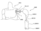
本実施の形態に係る人形は、図1に示すように、人形の胴体を構成する胴部1と、人形の腕を構成する腕部2と、胴部1の腕部2と対向する面に固定される滑止具3と、胴部1と腕部2とを互いに牽引する弾性体4とを備えている。
As shown in FIG. 1, the doll according to the present embodiment has a
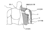
胴部1は、図2に示すように、中空状に形成されており、腕部2と接触する面に略球面状凹部5を有している。そして、胴部1の略球面状凹部5には、中空部6へと繋がる開口7が形成されていると共に該開口7を囲んで一周するように円環状の溝部8(図1参照)が形成されている。なお、略球面状凹部5の溝部8には、円環状の滑止具3が嵌め込まれる。
As shown in FIG. 2, the
腕部2は、人体の肩に当たる部分を構成する肩部材9と、人体の上腕に当たる部分を構成する上腕部材10及び人体の肘関節、前腕、手首関節及び手に当たる部分を構成する他の部材(図示せず)とから構成される腕部材11とに分割されている。そして、肩部材9と上腕部材10とは、中空状に形成されており、両部材9,10は、中空部12,13に通された弾性体4の牽引力によって所定方向に屈曲可能に連結されている。なお、本実施の形態に係る腕部2における肩部材9と上腕部材10とは、胴部1に沿わせて腕部2を伸ばすように人形を直立姿勢にした状態で胴部1方向に屈曲可能に連結されている。
The
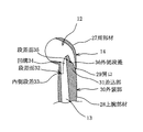
肩部材9は、図3に示すように、腕部2の外装を構成する外装部14と、外装部14から突出して胴部2の略球面状凹部5に嵌り込む略球面状凸部15と、外装部14から突出して上腕部材10における中空部13の開口に差し込まれる差込部16とから構成されており、肩部材9における外装部14と差込部16との境界には、肩部材9と上腕部材10との屈曲方向に対して内側(以下、「屈曲方向内側」という)に位置するように内側段差17が形成されている。なお、内側段差17は、上腕部材10と対向する段差面18を有しており、段差面18は溝状に窪んでいる。
As shown in FIG. 3, the
外装部14は、人体の肩に位置する三角筋を表現した表面形状に形成されている。また、略球面状凸部15には、略球面状凹部5に形成された開口7と対向するように中空部12へと繋がる縦割り状の開口19が形成されている。また、差込部16は、屈曲方向内側に位置する面が腕部2を伸ばした状態における軸線方向に沿って平坦状に形成されていると共に、肩部材9と上腕部材10との屈曲方向に対して外側(以下、「屈曲方向外側」という)に位置する面が先端に向かうに従って屈曲方向内側へ湾曲した形状に形成されており、これにより、差込部16は、先端に向かうに従って厚みが薄くなった舌片状に形成されている。そして、差込部16には、屈曲方向内側に位置する面に中空部12へと繋がる凹溝20が形成されており、屈曲方向外側に位置する面に上腕部材10と対向する段差面21を有する略V字状の外側段差22が形成されている。
The
上腕部材は、図4に示すように、人体の上腕に位置する上腕三頭筋及び上腕二頭筋を表現した表面形状に形成されており、肩側及び肘側に中空部13へと繋がる開口23,24を有している。上腕部材10における肩部材9の差込部16が差し込まれる肩側開口23は、屈曲方向内側に位置する開口端が肩部材9の内側段差17に沿うような形状に形成されていると共に、屈曲方向外側に位置する開口端が肩部材9の外側段差22に沿うような形状に形成されている。また、上腕部材10の内壁には、上腕部材10の肩側開口23に差し込まれる肩部材9の差込部16に形成された凹溝20に嵌り込むように二股状の突起25が形成されている。
As shown in FIG. 4, the upper arm member is formed in a surface shape representing the triceps and biceps brachii located on the upper arm of the human body, and has an opening connected to the
弾性体4としては、例えば、ゴム紐、バネなどを使用することができるが、これらのものに限らず、少なくとも各部材とが外れないように固定できる程度に強く牽引することができる張力を有するものであればよい。 As the elastic body 4, for example, a rubber string, a spring or the like can be used. However, the elastic body 4 is not limited thereto, and has at least a tension capable of being pulled so strongly that it can be fixed so as not to be detached from each member. Anything is acceptable.
次に、本実施の形態に係る人形の組み立て手順を説明する。 Next, a procedure for assembling a doll according to this embodiment will be described.
先ず、胴部1の肩部分に形成された略球面状凹部5の溝部8に滑止具3を嵌め込む。次に、胴部1に対して弾性体4を一方側の肩部分に形成された略球面状凹部5の開口7から中空部6を跨いで他方側の肩部分に形成された略球面状凹部5の開口7へ渡すように通す。次に、胴部1における一方側の略球面状凹部5の開口7から飛び出した弾性体4の一端を、肩部材9における略球面状凸部15の開口19から中空部12へと通して差込部16の凹溝20から引き出し、続いて、上腕部材10における肩側開口23から中空部13へと通して肘側開口24から引き出し、最後に、腕部2を構成する他の部材の中空部に通して該他の部材の中空部内に固定された掛止具に引っ掛ける(図示せず)。この時、胴部1の略球面状凹部5に肩部材9の略球面状凸部15が嵌り込んだ状態となると共に、肩部材9の差込部16が上腕部材10の肩側開口23に差し込まれた状態となる。
First, the anti-skid tool 3 is fitted into the groove portion 8 of the substantially spherical
次に、胴部1における他方側の略球面状凹部5の開口7から飛び出した弾性体4の他端を、肩部材9における略球面状凸部15の開口19から中空部12へと通して差込部16の凹溝20から引き出し、続いて、上腕部材10における肩側開口23から中空部13へと通して肘側開口24から引き出し、最後に、腕部2を構成する他の部材の中空部に通して該他の部材の中空部内に固定された掛止具に引っ掛ける(図示せず)。なお、弾性体4は引っ張った状態を維持し、そのままの状態で弾性体4の他端を掛止具に引っ掛ける。この時、胴部1の略球面状凹部5に肩部材9の略球面状凸部15が嵌り込んだ状態となると共に、肩部材9の差込部16が上腕部材10の肩側開口23に差し込まれた状態となる。これにより、胴部1と両腕部2が弾性体4によって互いに牽引された状態となる。
Next, the other end of the elastic body 4 protruding from the opening 7 of the substantially spherical
なお、肩部材9と上腕部材10とを屈曲させることなく腕部2を伸ばした状態にすると、図2に示すように、肩部材9と上腕部材10とは、上腕部材10における肩側開口23の屈曲方向内側が肩部材9の内側段差17に接触した状態となると共に、上腕部材10における肩側開口23の屈曲方向外側が肩部材9の差込部16における屈曲方向外側の面に接触した状態となる。この時、肩部材9における差込部16の外側段差22は上腕部材10の中空部13内に位置付けられて外部から視認できなくなり、また、上腕部材10における突起25は肩部材9における差込部16の凹溝20に嵌り込んだ状態となる。
When the
次に、本実施の形態に係る人形の腕部2を胴部1の前方へ曲げる動作を説明する。
Next, the operation | movement which bends the
先ず、胴部1の略球面状凹部5と肩部材9の略球面状凸部15とを摺動させて肩関節を可動させることより、肩部材9と上腕部材10とを屈曲させることなく伸ばした状態の腕部2を、胴部1の前方に真っ直ぐ突き出した状態(図5の(a)参照)から胴部1の前方に斜めに突き出した状態(図5の(b)参照)に回動させると、腕部2は、胴部1に対して所定角度α回動させた時点で該腕部2の回動方向に対して内側に位置する面が該胴部1と干渉して回動が規制される。
First, the
次に、胴部1と干渉して回動が規制された状態の腕部2における肩部材9と上腕部材10とを屈曲させると、図5の(c)に示すように、上腕部材10は、肩部材9に対して所定角度β屈曲させた時点で該上腕部材10の内壁が該肩部材9における差込部16の先端と干渉して屈曲が規制される。この時、肩部材9と上腕部材10とは、上腕部材10における肩側開口23の屈曲方向内側が肩部材9の内側段差17の溝に嵌り込むと共に、上腕部材10における肩側開口23の屈曲方向外側が肩部材の外側段差22に嵌り込んだ状態となる。
Next, when the
また、上腕部材10の中空部13に通される弾性体4は肩部材9と上腕部材10との屈曲前後で上腕部材10の二股状の突起25に嵌り込んだ状態が維持されるため、上腕部材10の中空部13内で弾性体4が位置ズレし難くなる。
Further, the elastic body 4 passed through the
なお、本実施の形態においては、図6の(a)に示すように、上腕部材10における肩側開口23の屈曲方向外側を人体の肩に位置する三角筋と人体の上腕に位置する上腕三頭筋及び上腕二頭筋との境界に当たる位置付け、かつ、当該境界に沿った形状に形成したため、腕部2を伸ばした状態において肩部材9と上腕部材10との境界が目立たなくなる。さらに、図6の(b)に示すように、肩部材9における外側段差22を前記境界と平行に位置付け、かつ、当該境界に沿った形状に形成したため、腕部2を屈曲させた状態においても肩部材9と上腕部材10との境界が目立たなくなる。
In this embodiment, as shown in FIG. 6 (a), the outer side in the bending direction of the shoulder-side opening 23 of the
本発明における腕部2は、本実施の形態のように肩、上腕、肘関節、前腕、手首関節及び手の各部材に分割した構成に限定されず、少なくとも肩から肘の間、より好ましくは、人体の肩に位置する三角筋と人体の上腕に位置する上腕三頭筋及び上腕二頭筋との間で分割した構成であればよい。
The
実施の形態2.
本実施の形態は前記実施の形態1における肩部材の変形例であり、図7において図1〜図5と同一符号は同一又は相当部分を示している。 This embodiment is a modification of the shoulder member in the first embodiment, and in FIG. 7, the same reference numerals as those in FIGS. 1 to 5 denote the same or corresponding parts.
本実施の形態に係る肩部材9には、外側段差22と平行に並ぶように外側段差26が形成されており、これにより、肩部材9と腕部材11との屈曲角度を二段階に調節することができる。
In the
なお、本実施の形態においては、肩部材9に外側段差を二つ形成したが、三つ以上形成してもよく、肩部材9に外側段差を複数形成した場合には、外側段差の数に応じて肩部材9と腕部材11の屈曲角度を段階的に調節することができるようになる。
In this embodiment, two outer steps are formed on the
実施の形態3. Embodiment 3 FIG.
本実施の形態は前記実施の形態1における肩部材と上腕部材の変形例であり、図8及び図9において図1〜図5と同一符号は同一又は相当部分を示している。 This embodiment is a modification of the shoulder member and the upper arm member in the first embodiment, and in FIGS. 8 and 9, the same reference numerals as those in FIGS. 1 to 5 denote the same or corresponding parts.
本実施の形態に係る肩部材27は、図8に示すように、腕部2の外装を構成する外装部14と、外装部14から突出して胴部1の略球面状凹部5に嵌り込む略球面状凸部15とから構成されており、外装部14の上腕部材28と対向する面には、中空部12へと繋がる開口29が形成されている。また、本実施の形態に係る上腕部材28は、腕部2の外装を構成する外装部30と、外装部30から突出して肩部材27の開口29に差し込まれる差込部31とから構成されており、上腕部材28の屈曲方向内側には、外装部30と差込部31との境界に沿って肩部材27と対向する段差面32を有する内側段差33が形成されている。そして、差込部31には、屈曲方向内側に位置する面に中空部13へと繋がる凹溝34が形成されており、屈曲方向外側に位置する面に肩部材27と対向する段差面35を有する外側段差36が形成されている。
As shown in FIG. 8, the
本実施の形態に係る肩部材27と上腕部材28との屈曲させると、図9に示すように、上腕部材28は、肩部材27に対して所定角度γ屈曲させた時点で該上腕部材28における差込部31の先端が該肩部材28の内壁と干渉して屈曲が規制される。この時、肩部材27と上腕部材28とは、肩部材27における開口29の屈曲方向内側が上腕部材28の内側段差33に嵌り込むと共に、肩部材27における開口29の屈曲方向外側が上腕部材28の外側段差36に嵌り込んだ状態となる。
When the
本実施の形態においても前記実施の形態1と同様の作用効果を得ることができる。 Also in this embodiment, the same effect as that of the first embodiment can be obtained.
1 胴部
2 腕部
3 滑止具
4 弾性体
5 略球面状凹部
6 中空部
7 開口
8 溝部
9 肩部材
10 上腕部材
11 腕部材
12 中空部
13 中空部
14 外装部
15 略球面状凸部
16 差込部
17 内側段差
18 段差面
19 開口
20 凹溝
21 段差面
22 外側段差
23 開口
24 開口
25 突起
26 外側段差
27 肩部材
28 上腕部材
29 開口
30 外装部
31 差込部
32 段差面
33 内側段差
34 凹溝
35 段差面
36 外側段差
DESCRIPTION OF
Claims (6)
A doll provided with the arm structure according to any one of claims 1 to 5.
Priority Applications (1)
| Application Number | Priority Date | Filing Date | Title |
|---|---|---|---|
| JP2011288098A JP5954614B2 (en) | 2011-12-28 | 2011-12-28 | Arm structure and doll having the arm structure |
Applications Claiming Priority (1)
| Application Number | Priority Date | Filing Date | Title |
|---|---|---|---|
| JP2011288098A JP5954614B2 (en) | 2011-12-28 | 2011-12-28 | Arm structure and doll having the arm structure |
Publications (3)
| Publication Number | Publication Date |
|---|---|
| JP2013135759A JP2013135759A (en) | 2013-07-11 |
| JP2013135759A5 JP2013135759A5 (en) | 2015-02-19 |
| JP5954614B2 true JP5954614B2 (en) | 2016-07-20 |
Family
ID=48912048
Family Applications (1)
| Application Number | Title | Priority Date | Filing Date |
|---|---|---|---|
| JP2011288098A Active JP5954614B2 (en) | 2011-12-28 | 2011-12-28 | Arm structure and doll having the arm structure |
Country Status (1)
| Country | Link |
|---|---|
| JP (1) | JP5954614B2 (en) |
Families Citing this family (1)
| Publication number | Priority date | Publication date | Assignee | Title |
|---|---|---|---|---|
| JP7342201B1 (en) | 2022-06-15 | 2023-09-11 | 株式会社バンダイ | toy |
Family Cites Families (9)
| Publication number | Priority date | Publication date | Assignee | Title |
|---|---|---|---|---|
| JPH0542873Y2 (en) * | 1987-04-21 | 1993-10-28 | ||
| JPH0378595U (en) * | 1989-11-29 | 1991-08-08 | ||
| JP2002153679A (en) * | 2001-10-05 | 2002-05-28 | Takara Co Ltd | Arm part structure of toy doll |
| JP3769687B2 (en) * | 2003-08-05 | 2006-04-26 | 株式会社ボークス | Doll joint structure |
| JP4636403B2 (en) * | 2004-10-27 | 2011-02-23 | 株式会社ボークス | Doll skeleton structure and the doll |
| JP4586971B2 (en) * | 2004-12-03 | 2010-11-24 | 株式会社ボークス | Doll leg structure and doll having the leg structure |
| JP4853664B2 (en) * | 2007-04-13 | 2012-01-11 | 株式会社ボークス | Doll joint structure and doll having the joint structure |
| JP4853663B2 (en) * | 2007-04-13 | 2012-01-11 | 株式会社ボークス | Doll joint structure and doll having the joint structure |
| JP5923810B2 (en) * | 2011-05-06 | 2016-05-25 | 株式会社ボークス | Joint structure and doll with the joint structure |
-
2011
- 2011-12-28 JP JP2011288098A patent/JP5954614B2/en active Active
Also Published As
| Publication number | Publication date |
|---|---|
| JP2013135759A (en) | 2013-07-11 |
Similar Documents
| Publication | Publication Date | Title |
|---|---|---|
| JP5331987B2 (en) | Doll joint structure and doll structure | |
| JP3341213B2 (en) | Doll toy | |
| WO2023243284A1 (en) | Movable structure for toy | |
| JP6030615B2 (en) | Doll toy shoulder joint structure and doll toy | |
| CN104519970A (en) | Wrist joint structure for figurine, ankle joint structure for figurine, and figurine | |
| JP2008126041A (en) | Constituent member of doll, toy robot, or the like | |
| JP5797244B2 (en) | Joint structure of doll body | |
| JP5954614B2 (en) | Arm structure and doll having the arm structure | |
| JP4853663B2 (en) | Doll joint structure and doll having the joint structure | |
| JP2005052427A (en) | Joint structure of doll and doll provided with the joint structure | |
| JP5923810B2 (en) | Joint structure and doll with the joint structure | |
| JP2012232021A (en) | Neck joint structure and doll with the same | |
| JP6712258B2 (en) | Parts connection structure and doll | |
| JP6144119B2 (en) | Doll joint structure | |
| KR102508932B1 (en) | Wearable hula hoop | |
| JP3769687B2 (en) | Doll joint structure | |
| JP4853664B2 (en) | Doll joint structure and doll having the joint structure | |
| US2615283A (en) | Jointed figure toy | |
| JP6222451B2 (en) | Hip joint structure and doll having the hip joint structure | |
| KR101132806B1 (en) | Ball-jointed doll | |
| JP4826769B2 (en) | Doll hip joint structure and doll having the hip joint structure | |
| JP3806845B2 (en) | Joint structure of doll toy and doll toy having the joint structure | |
| JP2009233287A (en) | Joint structure | |
| KR200391285Y1 (en) | Doll with sphere joint | |
| JP4771220B2 (en) | Doll hip joint structure and doll having the hip joint structure |
Legal Events
| Date | Code | Title | Description |
|---|---|---|---|
| A521 | Request for written amendment filed |
Free format text: JAPANESE INTERMEDIATE CODE: A523 Effective date: 20141219 |
|
| A621 | Written request for application examination |
Free format text: JAPANESE INTERMEDIATE CODE: A621 Effective date: 20141219 |
|
| A131 | Notification of reasons for refusal |
Free format text: JAPANESE INTERMEDIATE CODE: A131 Effective date: 20160308 |
|
| TRDD | Decision of grant or rejection written | ||
| A01 | Written decision to grant a patent or to grant a registration (utility model) |
Free format text: JAPANESE INTERMEDIATE CODE: A01 Effective date: 20160531 |
|
| A61 | First payment of annual fees (during grant procedure) |
Free format text: JAPANESE INTERMEDIATE CODE: A61 Effective date: 20160602 |
|
| R150 | Certificate of patent or registration of utility model |
Ref document number: 5954614 Country of ref document: JP Free format text: JAPANESE INTERMEDIATE CODE: R150 |
|
| R250 | Receipt of annual fees |
Free format text: JAPANESE INTERMEDIATE CODE: R250 |
|
| R250 | Receipt of annual fees |
Free format text: JAPANESE INTERMEDIATE CODE: R250 |
|
| R250 | Receipt of annual fees |
Free format text: JAPANESE INTERMEDIATE CODE: R250 |
|
| R250 | Receipt of annual fees |
Free format text: JAPANESE INTERMEDIATE CODE: R250 |


