JP5952571B2 - Insulator and rotating electric machine - Google Patents
Insulator and rotating electric machine Download PDFInfo
- Publication number
- JP5952571B2 JP5952571B2 JP2012016730A JP2012016730A JP5952571B2 JP 5952571 B2 JP5952571 B2 JP 5952571B2 JP 2012016730 A JP2012016730 A JP 2012016730A JP 2012016730 A JP2012016730 A JP 2012016730A JP 5952571 B2 JP5952571 B2 JP 5952571B2
- Authority
- JP
- Japan
- Prior art keywords
- terminal
- insulator
- connection
- stator
- phase
- Prior art date
- Legal status (The legal status is an assumption and is not a legal conclusion. Google has not performed a legal analysis and makes no representation as to the accuracy of the status listed.)
- Active
Links
Images


Description
この発明は、インシュレータ、及びこれを用いた回転電機に関するものである。 The present invention relates to an insulator and a rotating electric machine using the same.
例えば自動二輪車には、回転電機として、マグネットを備えた発電機が用いられている。この発電機は、自動二輪車のエンジンのクランクシャフトに連係される有底筒状のロータと、エンジンのケースの内側に固定されたステータとを備えている。ロータの内周面側にはマグネットが設けられている一方、ステータには複数のコイルが巻装されたティースがマグネットに対応するように設けられている。そして、ロータが回転することによりティースを通過する磁束量が変化し、これが起電力となってコイルに電流が流れるようになっている。 For example, in a motorcycle, a generator including a magnet is used as a rotating electrical machine. This generator includes a bottomed cylindrical rotor linked to a crankshaft of a motorcycle engine, and a stator fixed to the inside of the engine case. While a magnet is provided on the inner peripheral surface side of the rotor, teeth on which a plurality of coils are wound are provided on the stator so as to correspond to the magnet. The amount of magnetic flux passing through the teeth changes as the rotor rotates, and this becomes an electromotive force so that a current flows through the coil.
コイルは、例えばU相、V相、W相の3相構造からなり、各相のコイルの端末部を所定の結線構造(例えば、スター結線やデルタ結線)となるように結線する。また、コイルに流れる電流は、コイルと発電出力用リード線とのそれぞれの端末部を結線することにより、その発電出力用リード線を介してバッテリに蓄電されたり、付属電機機器に電力供給を行ったりする用途に用いられる。
ここで、各相のコイルの結線や、コイルと発電出力用リード線との結線は、例えばそれぞれの一端の端末部を重ね合わせてハンダ付けしたり、圧着スリーブを用いてカシメたりすることで行われる(例えば、特許文献1参照)。
The coil has, for example, a U-phase, V-phase, and W-phase three-phase structure, and the terminal portions of the coils of each phase are connected so as to have a predetermined connection structure (for example, star connection or delta connection). In addition, the current flowing in the coil is stored in the battery via the power generation output lead wire by connecting the terminal portions of the coil and the power generation output lead wire, or power is supplied to the attached electrical equipment. It is used for some applications.
Here, the coil connection of each phase and the connection between the coil and the lead wire for power generation output are performed by, for example, superposing and soldering the terminal portions of one end of each phase or crimping using a crimp sleeve. (See, for example, Patent Document 1).
しかしながら、上述の従来技術にあっては、コイルの結線作業が煩雑で、且つ結線精度が作業者のスキルに依存する部分が多く、製品毎に結線精度にばらつきが出てしまうという課題がある。
また、作業者によって結線スピードにばらつきが生じ、生産性が悪いという課題がある。
さらに、回転電機上でのコイルや発電出力用リード線との引き回しが煩雑になり、この分コイル等が嵩張って回転電機が大型化し、レイアウト性が低下するという課題がある。
However, in the above-described conventional technology, there is a problem that the coil connection work is complicated and the connection accuracy depends on the skill of the operator, and the connection accuracy varies from product to product.
In addition, there is a problem in that the connection speed varies depending on the operator and productivity is poor.
Furthermore, there is a problem that the coil and the lead wire for power generation output on the rotating electrical machine become complicated, and the coil and the like are bulky, the size of the rotating electrical machine is increased, and the layout is deteriorated.
そこで、この発明は、上述した事情に鑑みてなされたものであって、コイルの結線作業を簡素化させて結線精度を安定させることができる共に、生産性を向上させることができ、大型化を抑制してレイアウト性を向上させることができるインシュレータ、及び回転電機を提供するものである。 Therefore, the present invention has been made in view of the above-described circumstances, and can simplify the wire connection work to stabilize the connection accuracy, improve productivity, and increase the size. It is an object of the present invention to provide an insulator and a rotating electrical machine that can suppress and improve layout performance.
上記の課題を解決するために、本発明に係るインシュレータは、環状のステータコアと、このステータコアの外周面から径方向外側に向かって突設する複数のティースとを有するステータに装着され、各ティースと、これらティースに巻装される3相構造のコイルとの絶縁を図るためのインシュレータであって、前記インシュレータは、前記ステータの軸方向両側からそれぞれ装着されるように、一対の分割インシュレータからなり、各分割インシュレータは、前記ステータコアの外形状に対応するように形成されたリング部と、このリング部から径方向外側に向かって延び、各ティースを覆うように形成されたティース被覆部と、各相のコイルを結線する端子部とを有し、前記端子部は、前記3相構造のコイルに対応するように、第1接続部用端子と、第2接続部用端子と、第3接続部用端子との3つの端子からなり、前記第2接続部用端子と前記第3接続部用端子は同一形状であり、前記第2接続部用端子と前記第3接続部用端子は、一対の接続部と、これら一対の接続部を連結する帯状の連結部とからなり、前記一対の接続部は、前記連結部の両端から同一方向に屈曲延出しており、且つ前記連結部の長手方向に対する屈曲向きが同一であり、前記一対の分割インシュレータのうちの一方に、前記第1接続部用端子が配置されていると共に、前記第2接続部用端子、及び第3接続部用端子が前記一対の分割インシュレータのうちの他方に配置されていることを特徴とする。 In order to solve the above problems, an insulator according to the present invention is attached to a stator having an annular stator core and a plurality of teeth projecting radially outward from the outer peripheral surface of the stator core, , An insulator for insulation with a coil having a three-phase structure wound around the teeth, wherein the insulator includes a pair of divided insulators so as to be mounted from both axial sides of the stator, Each divided insulator includes a ring portion formed so as to correspond to the outer shape of the stator core, a teeth covering portion formed so as to extend radially outward from the ring portion and cover each tooth, and each phase A terminal portion for connecting the coil of the first connection, the terminal portion corresponding to the coil of the three-phase structure, the first connection And use the terminal, the terminal second connecting part consists of three terminals of the for the third connecting part terminal, the second connection portion terminal and the for the third connecting portions terminals have the same shape, the first The terminal for 2 connection parts and the terminal for 3rd connection part consist of a pair of connection parts and the strip-shaped connection part which connects these pair of connection parts, and the said pair of connection parts are from both ends of the said connection part. and out bend extends in the same direction, and a bending direction are the same with respect to the longitudinal direction of the connecting portion, the one of the pair of split insulators, together with the first connecting portion terminals are arranged, wherein The terminal for 2nd connection parts and the terminal for 3rd connection parts are arrange | positioned at the other of said pair of split insulators, It is characterized by the above-mentioned.
このように構成することで、端子部に各相のコイルを接続するだけでコイルの結線作業が完了するので、この結線作業を簡素化でき、作業者のスキルに対する依存度が低くなる。このため、コイルの結線精度を安定させることができると共に、生産性を向上させることができる。
また、一対の分割インシュレータのうちの一方に、各接続部用端子のうちの1種類の端子を配置すると共に、その他の2種類の端子を一対の分割インシュレータのうちの他方に配置するので、インシュレータ上でコイルが嵩張ることがなく、回転電機の大型化を抑制してレイアウト性を高めることができる。
With this configuration, the coil connection work can be completed simply by connecting the coils of the respective phases to the terminal portion. This connection work can be simplified and the dependence on the skill of the operator is reduced. For this reason, while being able to stabilize the connection accuracy of a coil, productivity can be improved.
In addition, since one type of terminal for each connection portion is arranged on one of the pair of split insulators and the other two types of terminals are arranged on the other of the pair of split insulators, the insulator Since the coil does not become bulky, the size of the rotating electrical machine can be suppressed and the layout can be improved.
本発明に係るインシュレータは、前記第1接続部用端子、第2接続部用端子、及び第3接続部用端子を、それぞれ前記リング部に沿って配置しており、前記第2接続部用端子、及び第3接続部用端子は、それぞれ前記リング部の径方向中心を通る直線を中心として線対称に配置したことを特徴とする。 In the insulator according to the present invention, the first connection portion terminal, the second connection portion terminal, and the third connection portion terminal are arranged along the ring portion, respectively , and the second connection portion terminal And the third connection portion terminals are arranged symmetrically about a straight line passing through the radial center of the ring portion .
このように構成することで、コイルの巻き終わり端近傍に各接続部用端子を配置することができ、各相のコイルのステータ上での嵩張りをさらに低減できる。このため、回転電機のレイアウト性をさらに高めることができる。
また、このように構成することで、3相のコイルを接続することにより形成される3つの接続部のうち、2つの接続部を、リング部の径方向中心を通る直線を中心としてどちらに配置することも可能になる。この分、インシュレータの配置自由度が高まり、インシュレータの汎用性を高めることができる。
さらに、任意の相におけるコイルの端末部の引き出し方向の自由度を高めることができるので、製品毎にコイルの端末部の引き出し方向を変化させることができる。このため、インシュレータの汎用性を高めることが可能になる。
By comprising in this way, the terminal for each connection part can be arrange | positioned in the coil end end vicinity, and the bulkiness on the stator of the coil of each phase can further be reduced. For this reason, the layout property of a rotary electric machine can further be improved.
Also, with this configuration, out of the three connecting portions formed by connecting the three-phase coils, the two connecting portions are arranged around the straight line passing through the radial center of the ring portion. It is also possible to do. Accordingly, the degree of freedom of arrangement of the insulator is increased, and the versatility of the insulator can be enhanced.
Furthermore, since the freedom degree of the drawing direction of the terminal part of a coil in arbitrary phases can be raised, the drawing direction of the coil terminal part can be changed for every product. For this reason, it becomes possible to improve the versatility of the insulator.
本発明に係るインシュレータは、前記リング部に、前記第2接続部用端子と、前記第3接続部用端子とをそれぞれ埋設したことを特徴とする。 Insulator according to the present invention, the ring portion, and wherein said a second connecting portion terminals, that is embedded respectively and said for the third connecting portions terminals.
このように構成することで、より確実に回転電機の大型化を抑制できる。また、ステータコアと車体側との接触面積を十分確保することができ、回転電機の取り付け安定性を向上できると共に、ステータの放熱性を高めることができる。
さらに、リング部に各接続部用端子を配置しても、ステータコア上に配索されるコイルが嵩張らないので、回転電機を車体に固定するための締結部材等をステータコア上に配置することが容易になる。このため、回転電機の設置スペースの省スペース化を図ることが可能になる。
By comprising in this way, the enlargement of a rotary electric machine can be suppressed more reliably. In addition, a sufficient contact area between the stator core and the vehicle body side can be secured, the mounting stability of the rotating electrical machine can be improved, and the heat dissipation of the stator can be enhanced.
Further, even if the terminals for each connection portion are arranged on the ring portion, the coil routed on the stator core is not bulky, so that it is easy to arrange a fastening member or the like for fixing the rotating electrical machine to the vehicle body on the stator core. become. For this reason, it is possible to reduce the installation space of the rotating electrical machine.
本発明に係る回転電機は、請求項1〜請求項3の何れか1項に記載のインシュレータが装着されたステータと、前記ステータに対して回転自在に設けられたロータとを備えたことを特徴とする。
A rotating electrical machine according to the present invention includes a stator to which the insulator according to any one of
このように構成することで、コイルの結線作業を簡素化させて結線精度を安定させることができる共に、生産性を向上させることができ、大型化を抑制してレイアウト性を向上させることが可能な回転電機を提供できる。 By configuring in this way, the coil connection work can be simplified to stabilize the connection accuracy, the productivity can be improved, and the layout can be improved by suppressing the increase in size. Can provide a simple rotating electric machine.
本発明によれば、端子部に各相のコイルを接続するだけでコイルの結線作業が完了するので、この結線作業を簡素化でき、作業者のスキルに対する依存度が低くなる。このため、コイルの結線精度を安定させることができると共に、生産性を向上させることができる。
また、一対の分割インシュレータのうちの一方に、各相用端子のうちの1つの端子を配置すると共に、その他の2つの端子を一対の分割インシュレータのうちの他方に配置するので、インシュレータ上でコイルが嵩張ることがなく、回転電機の大型化を抑制してレイアウト性を高めることができる。
According to the present invention, since the coil connection work is completed simply by connecting the coils of the respective phases to the terminal portion, the connection work can be simplified and the dependence on the skill of the operator is reduced. For this reason, while being able to stabilize the connection accuracy of a coil, productivity can be improved.
Moreover, since one terminal for each phase is disposed on one of the pair of split insulators and the other two terminals are disposed on the other of the pair of split insulators, a coil is formed on the insulator. Therefore, the size of the rotating electrical machine can be suppressed and the layout can be improved.
(磁石発電機)
次に、この発明の実施形態を図面に基づいて説明する。
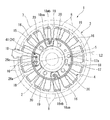
図1は、本発明に係る回転電機である磁石発電機1を一方からみた平面図、図2は、磁石発電機1を他方からみた平面図である。
図1、図2に示すように、磁石発電機1は、例えば自動二輪車に用いられるアウターロータ型の発電機であって、エンジンのクランクシャフト2の先端に固定されたロータ3と、エンジンのケース(不図示)に固定されるステータ4とを備えている。
(Magnet generator)
Next, embodiments of the present invention will be described with reference to the drawings.
FIG. 1 is a plan view of a
As shown in FIGS. 1 and 2, the
ロータ3は、有底筒状に形成されたものであって、底壁(不図示)の径方向中央にロータボス5が突設されている。このロータボス5に、クランクシャフト2が取り付けられている。また、ロータ3の周壁7には、内周面側に複数の永久磁石8が周方向に磁極が交互となるように設けられている。
The
ステータ4は、円環状のステータコア17を有している。ステータコア17は、磁性材料の板材を軸線方向に積層して形成したものであって、径方向中央にロータボス5が挿通可能なボス孔15が形成されている。また、ステータコア17には、ステータ4を不図示のエンジンのケースに締結固定するためのボルト孔20が4箇所周方向に略等間隔に形成されている。
ここで、ステータコア17の端面は、エンジンのケースとの接触面として設定される。ステータコア17の接触面とエンジンのケースとを接触させた状態で、ボルト孔20に不図示のボルトを挿通してエンジンのケースにステータ4を締結固定する。このように構成することで、エンジンのケースにステータ4を安定して固定することができると共に、ステータ4の放熱性を高めることができる。
The
Here, the end surface of the
さらに、ステータコア17には、放射状に径方向外側に向かって延出する平面視T字形状のティース16が等間隔に18個設けられている。
尚、各ティース16は、周方向で隣り合うティース16の形状が異なり、且つ周方向で60度間隔に配置されているティース16同士の形状が同一形状になっている、所謂異形コアである。しかしながら、これに限られるものではなく、各ティース16が同一形状であってもよいし、また、ティース16の個数も18個に限られるものではない。
Further, the
Each
ステータ4の外周には、隣接するティース16間に蟻溝状のスロット19が形成されている。このスロット19は、ティース16に電機子コイル18を巻装するためのコイル受け入れ口の役割を有する。スロット19は軸線方向に沿って延びており、周方向に沿って等間隔に18個形成されている。また、ステータコア17には、絶縁材であるインシュレータ24が装着されており、各ティース16には、インシュレータ24の上から電機子コイル18が多数回巻回されるようになっている。
On the outer periphery of the
ここで、各ティース16は、それぞれU相、V相、W相が周方向にこの順で割り当てられている。このため、各ティース16に巻装されている電機子コイル18は、それぞれ対応する相に設定される。そして、U相、V相、W相の電機子コイル18は、それぞれの端末部がデルタ結線により結線されている。この結線構造について、以下に詳述する。
Here, in each
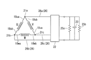
図3は、電機子コイル18の結線構造の一例を示す結線図である。
同図に示すように、例えば、U相の電機子コイル18の巻き始め端18uaと、V相の電機子コイル18の巻き終わり端vbとが接続されて接続部21aを形成する。また、U相の電機子コイル18の巻き終わり端18ubと、W相の電機子コイル18の巻き始め端18waとが接続されて接続部21bを形成する。さらに、V相の電機子コイル18の巻き始め端vaと、W相の電機子コイル18の巻き終わり端wbとが接続されて接続部21cを形成する。
FIG. 3 is a connection diagram illustrating an example of a connection structure of the
As shown in the figure, for example, the winding start end 18ua of the
図1、図3に示すように、デルタ結線により結線された各相の電機子コイル18の3つの接続部21a,21b,21cは、ハーネス26を介して整流器22に接続され、さらに、整流器22が抵抗25a,25bを介してバッテリ23に接続されている。
ハーネス26は、3本のリード線26a,26b,26cにより構成されており、これらリード線26a,26b,26cが、各接続部21a,21b,21cと整流器22とを電気的に接続している。すなわち、例えば、リード線26aの端末部は、接続部21aと整流器22とに接続されている。また、リード線26bの端末部は、接続部21bと整流器22とに接続されている。さらに、リード線26cの端末部は、接続部21cと整流器22とに接続されている。
As shown in FIGS. 1 and 3, the three
The
(インシュレータ)
ステータコア17に装着されるインシュレータ24は、樹脂により形成されたものであって、軸方向一端側(図1における紙面手前側)からステータ4に装着された第1インシュレータ31と、軸方向他端側(図2における紙面手前側)からステータ4に装着された第2インシュレータ41とにより、軸方向において2分割に構成されている。つまり、インシュレータ24は、軸方向に分割された形の第1インシュレータ31、及び第2インシュレータ41によって、ステータ4を軸方向両側から挟持するように装着してなる。
(Insulator)
The
(第1インシュレータ)
図4は、第1インシュレータ31の斜視図である。
図1、図4に示すように、第1インシュレータ31は、ステータコア17の外形状に対応するように略円環状に形成されたリング部32と、このリング部32の外周面から放射状に径方向外側に向かって延出する複数のティース被覆部33とが一体成形されたものである。
(First insulator)
FIG. 4 is a perspective view of the
As shown in FIGS. 1 and 4, the
リング部32は、中央に開口部を有する環状の部材であって、ステータコア17の外周面を覆う複数の下段リング部32aと、下段リング部32aの端縁から軸方向に立設し、各下段リング部32aを連結する上段リング部32bとが一体成形されている。
The
上段リング部32bは、ステータコア17に形成されている各ボルト孔20を径方向外側から取り囲むように形成されてものであって、ステータ4の径方向外側(ティース16側)と径方向内側(ステータコア17側)との間を仕切っている。上段リング部32bによって、ティース16に巻回された電機子コイル18や各ティース16間に引き回される電機子コイル18がステータコア17上(上段リング部32bより径方向内側)に配索されることを防止できる。
The
また、上段リング部32bには、内周面側に一対の台座部34a,34bが一体成形されている。台座部34a,34bは、上段リング部32bの形状に対応するように、円弧状に形成され、且つ上段リング部32bから径方向内側に突出するように形成されている。そして、リング部32の中心軸C1を通る任意の直線L1を中心にして線対称に配置されている。
台座部34a,34bは、ハーネス26を構成する3本のリード線26a,26b,26cうちの1本、例えばリード線26bと、電機子コイル18の接続部21bとを接続するためのものである。
The
The
ここで、リード線26bと電機子コイル18の接続部21bとを接続するにあたって、一対の台座部34a,34bが設けられているのは、磁石発電機1の仕様に応じて電機子コイル18の端末部の引き出し方向が変わるからである。より具体的には、例えば、磁石発電機1の仕様に応じて一対の台座部34a,34bの何れか一方に、U相の電機子コイル18の巻き終わり端18ub、及びW相の電機子コイル18の巻き始め端18waを引き出すことができるようになっている。そして、引き出された位置の近傍に存在する台座部34a,34bを使用することにより、電機子コイル18やリード線26bの配線長さを短くすることができる。
Here, when connecting the
また、一対の台座部34a,34bには、円筒部36が磁石発電機1の軸方向他端側(図3における下側)に向かって突出するように一体成形されている。円筒部36は、ハーネス26を構成する3本のリード線26a,26b,26cうちの2本、例えばリード線26a,26cを第2インシュレータ41側に向かって配索するためのものである。円筒部36の直径は、2本のリード線26a,26cを挿通可能な大きさに設定されている。ここで、ステータコア17には、円筒部36に対応する位置に、この円筒部36を挿通可能な挿通孔17aが軸方向に貫通するように形成されている。
In addition, the
また、一対の台座部34a,34bには、円筒部36を避けた位置に、例えば、リード線26bと電機子コイル18の接続部21bとを接続するため第1端子35が埋設されている。さらに、1対の台座部34a,34bには、台座部34a,34bの円筒部36に対応する一辺を除いた外周縁に壁部37が、磁石発電機1の軸方向一端側(図3における上側)に向かって立ち上がるように一体成形されている。壁部37は、第1端子35の周囲を、外部と隔てるための隔壁として機能している。
In addition, a
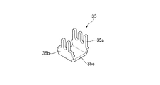
図5は、第1端子35の斜視図である。
同図に示すように、第1端子35は断面略コの字状に形成されており、電機子コイル18が接続されるコイル接続部35aと、ハーネス26を構成する3本のリード線26a,26b,26cのうちの1本が接続されるリード線接続部35bと、これらコイル接続部35aとリード線接続部35bとを連結する連結部35cとにより構成されている。
FIG. 5 is a perspective view of the
As shown in the figure, the
コイル接続部35aの先端部は、例えば、U相の電機子コイル18の巻き終わり端18ub、及びW相の電機子コイル18の巻き始め端18waの2本を挟持可能なように、三つ又状に形成されている。一方、リード線接続部35bは、例えば、3本のリード線26a,26b,26cのうちのリード線26bが挟持可能なように、二又状に形成されている。
このように構成された第1端子35は、連結部35cが台座部34a,34bに埋設される一方、コイル接続部35aの先端、及びリード線接続部35bの先端が磁石発電機1の軸方向一端側(図3における上側)に向かって突出するように設けられている。
The front end of the
In the
図4に戻り、下段リング部32aには、その端縁から軸方向に沿って切り欠かれた複数(例えば、18箇所)の切欠き部38が周方向に沿って等間隔に形成されている。そして、この切欠き部38の周縁を囲むようにティース被覆部33が形成されている。
ティース被覆部33は、ティース16と電機子コイル18とを絶縁するためのものであって、下段リング部32aの外周面、つまり切欠き部38の周縁から径方向外側に向かって延出する巻胴部61と、巻胴部61の先端から巻胴部61の延出方向に交差する方向に延出する周壁部62とを備えた平面視T字形状のものである。
Returning to FIG. 4, the
The
ティース被覆部33は、リング部32の周方向に沿って等間隔に18個形成されている。つまり、各ティース被覆部33は、上述したティース16と平面視で略同形状、且つ同数形成されており、各ティース16の軸方向一端側を被覆するものである。すなわち、ティース被覆部33の巻胴部61は、ティース16の軸方向一端側(図1における紙面手前側)からティース16の側面にかけて覆うように形成されており、表面61aと側面61bとを有している。
一方、周壁部62は、巻胴部61の先端から周方向及び径方向に延出しており、ティース16の先端側を覆うように形成されている。なお、周壁部62の先端側は径方向外側に向けて開放されている。
Eighteen
On the other hand, the
(第2インシュレータ)
図6は、第2インシュレータ41の斜視図である。
図2、図6に示すように、第2インシュレータ41は、ステータコア17の外形状に対応するように略円環状に形成されたリング部42と、このリング部42の外周面から放射状に径方向外側に向かって延出する複数のティース被覆部33とが一体成形されたものである。
(Second insulator)
FIG. 6 is a perspective view of the
As shown in FIGS. 2 and 6, the
ここで、リング部42は、中央に開口部を有する環状の部材であって、ステータコア17の外周面を覆う複数の下段リング部42aと、下段リング部42aの端縁から軸方向に立設し、各下段リング部42aを連結する上段リング部42bとが一体成形されている点は、前述の第1インシュレータ31と同様である。
尚、ティース被覆部33、及び下段リング部42aは、前述の第1インシュレータ31のティース被覆部33、及び下段リング部32aと同一形状であるので、同一符号を付して説明を省略する。
Here, the
In addition, since the teeth coating |
上段リング部42bは、ステータコア17に形成されている各ボルト孔20を径方向外側から取り囲むように形成されており、内周面側に3つの台座部44a,44b,44cが一体成形されている。3つの台座部44a,44b,44cは、ハーネス26を構成する3本のリード線26a,26b,26cうちの2本、例えばリード線26a,26cと、電機子コイル18の接続部21a,21cとをそれぞれ接続するためのものであって、1つの大台座部44aと2つの小台座部44b,44cとにより構成されている。
The
大台座部44aは、上段リング部42bの形状に対応するように、円弧状に形成され、且つ上段リング部42bから径方向内側に突出するように形成されている。また、大台座部44aには、長手方向略中央に円筒部46が磁石発電機1の軸方向一端側(図6における下側)に向かって突出するように一体成形されている。
The
円筒部46は、ハーネス26を構成する3本のリード線26a,26b,26cのうちの2本、例えばリード線26a,26cを第1インシュレータ31側から引き込むためのものである。円筒部46の軸方向の長さは、第1インシュレータ31の円筒部36の軸方向の長さとほぼ同一長さに設定されている。また、円筒部46の直径は、第1インシュレータ31の円筒部36の直径とほぼ同一径に設定されている。
そして、ステータコア17に第1インシュレータ31、及び第2インシュレータ41をそれぞれ所定の向きで装着した状態にあっては、第1インシュレータ31の円筒部36と、第2インシュレータ41の円筒部46とが軸方向で重なり合うようになっている。
The
When the
さらに、大台座部44aの長手方向両側には、それぞれ例えば、リード線26aと電機子コイル18の接続部21aとを接続すると共に、リード線26cと電機子コイル18の接続部21cとを接続するための2つの第2端子51の各々一部が突出されている。これら2つの第2端子51についての詳細は後述する。
Furthermore, for example, the
大台座部44aの外周縁には、壁部47が円筒部46に対応する位置を避けるように、且つ2つの第2端子51の突出した部位を取り囲むように一体成形されている。また、壁部47は、磁石発電機1の軸方向他端側(図6における上側)に向かって立ち上がるように一体成形されている。壁部47は、2つの第2端子51の突出した部位の周囲を、外部と隔てるための隔壁として機能している。
The
一方、2つの小台座部44b,44cは、それぞれ大台座部44aから周方向に所定間隔をあけて、且つリング部42の中心軸C2を通る任意の直線L2を中心にして線対称に配置されている。各小台座部44b,44cは、上段リング部42bから径方向内側に突出するように形成されており、その周方向の長さは、大台座部44aの周方向の長さよりも短く設定されている。
On the other hand, the two
各小台座部44b,44cにも、それぞれ第2端子51の一部が突出されている。また、各小台座部44b,44cの外周縁には、第2端子51の突出した部位の周囲を取り囲むように、壁部48が磁石発電機1の軸方向他端側(図6における上側)に向かって立ち上がるように一体成形されている。壁部48も、第2端子51の突出した部位の周囲を、外部と隔てるための隔壁として機能している。
A part of the
図7は、第2端子51の斜視図である。
同図に示すように、第2端子51は、大台座部44a、及び小台座部44bから突出する一対の接続部51a,51aと、これら一対の接続部51a,51aを連結する帯状の連結部51bとにより構成されている。
接続部51aの先端部は、電機子コイル18の端末やハーネス26を構成するリード線26a,26b,26cを挟持可能なように、三つ又状に形成されている。そして、各接続部51aは、磁石発電機1の軸方向他端側(図6における上側)に向かって突出するように設けられている。
FIG. 7 is a perspective view of the
As shown in the figure, the
The distal end portion of the connecting
一方、連結部51bは、上段リング部42bの形状に対応するように湾曲形成されており、上段リング部42bに埋設されている。すなわち、図6において、第2インシュレータ41の中心から左側に露出している2つの接続部51a,51aが、それぞれ連結部51bにより連結され、一体化されている。一方、第2インシュレータ41の中心から右側に露出している2つの接続部51a,51aが、それぞれ連結部51bにより連結され、一体化されている。
On the other hand, the connecting
ここで、大台座部44aから突出している2つの接続部51aのうち、一方には3本のリード線26a,26b,26cのうちのリード線26aが接続されており、他方にはリード線26cが接続されている。
そして、リード線26aが接続されている側の小台座部44bから突出している接続部51aには、例えば、U相の電機子コイル18の巻き始め端18ua、及びV相の電機子コイル18の巻き終わり端18vbが接続されている。
Here, of the two connecting
The connecting
一方、リード線26cが接続されている側の小台座部44cから突出している接続部51aには、例えば、V相の電機子コイル18の巻き始め端18va、及びW相の電機子コイル18の巻き終わり端18wbが接続されている。
これにより、各相の電機子コイル18、及び3本のリード線26a,26b,26cは、図3に示すような結線構造になる。
On the other hand, the connecting
Thereby, the
(インシュレータの装着作業と電機子コイル、及びハーネスの結線作業)
次に、インシュレータ24(31,41)のステータ4への装着作業と、各相の電機子コイル18の結線作業について説明する。
まず、ステータ4の両端側から、それぞれこのステータ4を挟持するように第1インシュレータ31、及び第2インシュレータ41を装着する。このとき、第1インシュレータ31は、U相の電機子コイル18の巻き終わり端18ub、又はW相の電機子コイル18の巻き始め端18waの引き出し位置の近傍に、一対の台座部34a,34bの何れか一方が位置するように装着される。
(Insulator installation work and armature coil and harness connection work)
Next, the mounting operation of the insulator 24 (31, 41) to the
First, the
ここで、ステータ4の各ティース16は、周方向で隣り合うティース16の形状が異なり、且つ周方向で60度間隔に配置されているティース16同士の形状が同一形状になっている、所謂異形コアである。第1インシュレータ31、及び第2インシュレータ41のティース被覆部33も、ステータ4のティース16に対応するように形成されているので、各インシュレータ31,41は、周方向に60度ずつずらしながら装着することが可能である。
すなわち、周方向に60度間隔で、U相の電機子コイル18の巻き終わり端18ub、又はW相の電機子コイル18の巻き始め端18waの引き出し位置が最も近くなる位置に、一対の台座部34a,34bの何れか一方が位置するように第1インシュレータ31を装着する。
Here, the
That is, the pair of pedestal portions are located at positions at which the winding end ends 18ub of the U-phase armature coils 18 or the winding start ends 18wa of the W-phase armature coils 18 are closest to each other at intervals of 60 degrees in the circumferential direction. The
一方、第2インシュレータ41は、この第2インシュレータ41の円筒部46と、第1インシュレータ31の一対の台座部34a,34bのうち、使用される台座部34a,34bの円筒部36とが軸方向で重なるようにステータ4に装着される。
ここで、各ティース16は、それぞれU相、V相、W相が周方向にこの順で割り当てられているので、U相の電機子コイル18の巻き終わり端18ub、又はW相の電機子コイル18の巻き始め端18waの引き出し位置が決定することにより、その他の巻き始め端18ua,18va、及び巻き終わり端18vb,18wbの位置も決定される。このようなことを考慮し、第2インシュレータ41における大台座部44aと小台座部44bとの周方向の間隔が設定される。
On the other hand, in the
Here, since the U phase, the V phase, and the W phase are respectively assigned in this order in the circumferential direction in each
第1インシュレータ31、及び第2インシュレータ41の装着が完了した後、これらのティース被覆部33の上から、それぞれ電機子コイル18を巻回する。そして、U相の電機子コイル18の巻き終わり端18ub、及びW相の電機子コイル18の巻き始め端18waを第1インシュレータ31側に引き出す。一方、その他の巻き始め端18ua,18va、及び巻き終わり端18vb,18wbを、第1インシュレータ31とは反対側の第2インシュレータ41側に引き出す。
After the mounting of the
続いて、引き出されたU相の電機子コイル18の巻き終わり端18ub、及びW相の電機子コイル18の巻き始め端18waを、それぞれ第1端子35のコイル接続部35aの先端部に挟み込む。そして、コイル接続部35aの先端部をカシメて仮固定した後、コイル接続部35aと、巻き終わり端18ub、及び巻き始め端18waとをハンダにより接続する。これにより、コイル接続部35aと、巻き終わり端18ub、及び巻き始め端18waとの接続が完了する。
Subsequently, the winding
続いて、U相の電機子コイル18の巻き始め端18ua、及びV相の電機子コイル18の巻き終わり端18vbを、これらの引き出し位置近傍に存在する第2端子における接続部51aの先端部に挟み込む。そして、接続部51aの先端部をカシメて仮固定した後、接続部51aと、巻き始め端18ua、及び巻き終わり端18vbとをハンダにより接続する。
Subsequently, the winding start end 18ua of the
同様に、V相の電機子コイル18の巻き始め端18va、及びW相の電機子コイル18の巻き終わり端18wbの巻き終わり端を、これらの引き出し位置近傍に存在する第2端子における接続部51aの先端部に挟み込む。そして、接続部51aの先端部をカシメて仮固定した後、接続部51aと、巻き始め端18va、及び巻き終わり端18wbとをハンダにより接続する。これにより、電機子コイル18の結線作業が完了する。
Similarly, the winding start end 18va of the V-
続いて、電機子コイル18の結線作業が完了した磁石発電機1を不図示のエンジンのケースに締結固定する。そして、ハーネス26を磁石発電機1に対応する位置まで引き込み、3本のリード線26a,26b,26cを所定の位置に配索する。
すなわち、リード線26bを第1インシュレータ31における第1端子35のリード線接続部35bの先端部に挟み込む。そして、リード線接続部35bの先端部をカシメて仮固定した後、リード線接続部35bと、リード線26bとをハンダにより接続する。
Subsequently, the
That is, the
一方、リード線26a,26cを第1インシュレータ31側から、この第1インシュレータ31の円筒部36に挿入し、第2インシュレータ41の円筒部46から引き出す。そして、それぞれリード線26a,26cを、第2インシュレータ41の大台座部44aに突出している第2端子51の接続部51aの先端部に挟み込む。そして、各接続部51aの先端部をカシメて仮固定した後、各接続部51aと、リード線26a,26cとをハンダにより接続する。これにより、磁石発電機1へのハーネス26の結線作業が完了する。
On the other hand, the
このような構成のもと、エンジンが始動すると、クランクシャフト2の先端に固定されたロータ3が回転し、これにより生じる磁束の変化によって各相の電機子コイル18に誘導起電力が生じる。そして、各相の電機子コイル18に発生する電流が整流器22を介してバッテリ23に蓄電される。
Under such a configuration, when the engine starts, the
尚、磁石発電機1をエンジンスタータ用として用いることも可能である。このように用いる場合、バッテリ23の電力を整流器22を介してか駆動の電機子コイル18に供給する。すると、各ティース16に磁界が発生し、この磁界とロータ3に設けられている永久磁石8との間に磁気的な吸引力や反発力が生じる。これにより、ロータ3が回転し、クランクシャフト2が駆動することによってエンジンが始動する。
In addition, it is also possible to use the
(効果)
したがって、上述の実施形態によれば、第1インシュレータ31に第1端子35が設けられ、第2インシュレータ41に第2端子51が設けられているので、各端子35,51に所定の相の電機子コイル18を接続するだけで、電機子コイル18の結線作業が完了する。このため、電機子コイル18の結線精度を安定させることができると共に、生産性を向上させることができる。
(effect)
Therefore, according to the above-mentioned embodiment, since the
また、第1インシュレータ31と第2インシュレータとのそれぞれ別々に第1端子35と第2端子51を設けることにより、ステータ4の同一端面上に3相の電機子コイル18の全てが配索されないようになっている。つまり、例えば、U相の電機子コイル18の巻き終わり端18ub、及びW相の電機子コイル18の巻き始め端18waと、その他の巻き始め端18ua,18va、及び巻き終わり端18vb,18wbとの引き出し方向がステータ4の軸方向で互いに反対になっている。このため、第1インシュレータ31、及び第2インシュレータ41上で電機子コイル18が嵩張ることがなく、磁石発電機1の大型化を抑制してレイアウト性を高めることができる。
In addition, by providing the
さらに、第1インシュレータ31の上段リング部42bに沿って一体成形されている台座部34a,34bに第1端子35が配置されていると共に、第2インシュレータ41の上段リング部42bに沿って一体成形されている台座部44、つまり、大台座部44a、及び小台座部44bに第2端子51が配置されている。このため、各相の電機子コイル18の巻き始め端18ua,18va,18wa、及び巻き終わり端18ub,vb,wbの引き出し位置の近傍に、それぞれ対応する端子35,51を位置させることができ、各相の電機子コイル18のステータ4上での嵩張りを確実に低減できる。よって、磁石発電機1のレイアウト性をさらに高めることができる。
Further, the
そして、第1インシュレータ31に第1端子35が埋設されていると共に、第2インシュレータ41に第2端子51が埋設されているので、ステータコア17上に不図示のエンジンのケースとの接触面積を十分確保することができ、磁石発電機1の取り付け安定性を向上できると共に、ステータ4の放熱性を高めることができる。
さらに、第1インシュレータ31の上段リング部32bに第1端子35を配置すると共に、第2インシュレータ41の上段リング部42bに第2端子51を配置しても、ステータコア17上に配索されるコイルが嵩張らないので、磁石発電機1をエンジンのケースに締結固定するためのボルト孔20をステータコア17上に形成することが容易になる。このため、磁石発電機1の設置スペースの省スペース化を図ることが可能になる。
And since the
Further, the
また、第1インシュレータ31の上段リング部32bには、一対の台座部34a,34bがリング部32の中心軸C1を通る任意の直線L1を中心にして線対称に配置されている。このため、3相の電機子コイル18のうち、2相の電機子コイル18の端末部、例えば、U相の電機子コイル18の巻き終わり端18ub、又はW相の電機子コイル18の巻き始め端18waの引き出し位置の近傍に、一対の台座部34a,34bの何れか一方を配置すればよい。換言すれば、一対の台座部34a,34bの何れか一方に向かって2相の電機子コイル18の端末部を引き出せばよい。
したがって、インシュレータ24の配置自由度が高まり、インシュレータ24の汎用性を高めることができる。また、電機子コイル18の端末部を無駄に引き回す必要がなくなり、電機子コイル18のステータ4上での嵩張りを低減することができると共に、電機子コイル18の線材コストを低減することができる。
In addition, a pair of
Therefore, the arrangement | positioning freedom degree of the
さらに、第2インシュレータの上段リング部42bには、2つの小台座部44b,44cがリング部42の中心軸C2を通る任意の直線L2を中心にして線対称に配置されている。このため、3相の電機子コイル18のうち、2相の電機子コイル18の端末部を2つの小台座部44b,44cの何れにも配索させることができる。すなわち、各相のティース16に設定されているU相、V相、W相の順番に関わらず、それぞれ2つの小台座部44b,44cに近い箇所から引き出された電機子コイル18の端末部を、そのまま近くの小台座部44b,44cの接続部51aに接続させることができる。
Further, two
より具体的には、上述の実施形態では、小台座部44bから突出している接続部51aに、例えば、U相の電機子コイル18の巻き始め端18ua、及びV相の電機子コイル18の巻き終わり端18vbを接続した場合について説明したが、小台座部44cから突出している接続部51aに、U相の電機子コイル18の巻き始め端18ua、及びV相の電機子コイル18の巻き終わり端18vbを接続することも可能である。このように、電機子コイル18の引き出し位置を選択することが可能になるので、インシュレータ24の汎用性を高めることができる。
More specifically, in the above-described embodiment, for example, the winding start end 18ua of the
尚、本発明は上述の実施形態に限られるものではなく、本発明の趣旨を逸脱しない範囲において、上述の実施形態に種々の変更を加えたものを含む。
例えば、上述の実施形態では、回転電機の一例としてアウターロータ型の磁石発電機1について説明したが、これに限られるものではなく、例えばインナーロータ型の磁石発電機や、3相のスタータジェネレータ等に本発明のインシュレータ24を適用することも可能である。
The present invention is not limited to the above-described embodiment, and includes various modifications made to the above-described embodiment without departing from the spirit of the present invention.
For example, in the above-described embodiment, the outer rotor
また、上述の実施形態では、第1インシュレータ31の一対の台座部34a,34bの何れか一方の第1端子35に電機子コイル18の巻き始め端18wa、及び巻き終わり端18ubと、リード線26bとを接続し、第2インシュレータ41の2つの接続部51aのうちの一方に、電機子コイル18の巻き始め端18ua、及び巻き終わり端18vbと、リード線26aとを接続し、他方に、電機子コイル18の巻き始め端18va、及び巻き終わり端18wbと、リード線26cとを接続した場合について説明した。しかしながら、これに限られるものではなく、各相の電機子コイル18がデルタ結線されていればよく、また、各リード線26a,26b,26cは、それぞれ任意の接続部21a,21b,21cと整流器22との間に接続されていればよい。
In the above-described embodiment, the winding start end 18wa and the winding end end 18ub of the
さらに、上述の実施形態では、第1インシュレータ31のリング部32、及び第2インシュレータ41のリング部42がそれぞれステータコア17の外形状に対応するように、略円環状に形成されている場合について説明した。しかしながら、これに限られるものではなく、ステータコア17の外形状に対応するように形成されていればよい。より具体的には、リング部32,42は環状に形成されていればよく、例えば、多角形状であってもよい。
Furthermore, in the above-described embodiment, a case where the
そして、上述の実施形態では、図3に示すように、3相の電機子コイル18により、1つのデルタ結線構造を形成している場合について説明した。しかしながら、これに限られるものではなく、3相の電機子コイル18により、複数のデルタ結線構造を形成してもよい。この場合、各インシュレータ31,41に設けられる端子35,51の個数もデルタ結線構造の個数に応じて増加させてよい。
例えば、3相の電機子コイル18により、2つのデルタ結線構造を形成する場合、第2インシュレータ41に4つの第2端子51を設ける。さらに、第1インシュレータ31に設けられている2つの第1端子35,35を両方使用する。
And in the above-mentioned embodiment, as shown in FIG. 3, the case where one delta connection structure was formed with the three-
For example, when two delta connection structures are formed by the three-
また、上述の実施形態では、第2インシュレータ41に同一形状の2つの第2端子51を設けた場合について説明した。しかしながら、これに限られるものではなく、電機子コイル18の3つの接続部21a,21b,21cのうち、2つの接続部が形成可能で、且つこれら接続部が所定のリード線26a,26b,26cに接続可能であればよい。このため、第2インシュレータ41に形状の異なる2つの端子を設けてもよい。
さらに、第1インシュレータ31に設けられている第1端子35も図5に示す形状に限られるものではなく、3つの接続部21a,21b,21cのうち、1つの接続部が形成可能で、且つ所定のリード線26a,26b,26cが接続可能な形状であればよい。
Moreover, in the above-mentioned embodiment, the case where the
Furthermore, the
1 磁石発電機(回転電機)
3 ロータ
4 ステータ
16 ティース
17 ステータコア
18 電機子コイル
21a,21b,21c 接続部
24 インシュレータ
31 第1インシュレータ(分割インシュレータ)
32 リング部
33 ティース被覆部
35 第1端子(端子部、第1接続部用端子)
41 第2インシュレータ(分割インシュレータ)
51 第2端子(端子部、第2接続部用端子、第3接続部用端子)
51a 接続部
51b 連結部
1 Magnet generator (rotary electric machine)
3
32
41 Second insulator (split insulator)
51 2nd terminal (terminal part, 2nd connection part terminal, 3rd connection part terminal)
51a connection
51b connecting part
Claims (4)
各ティースと、これらティースに巻装される3相構造のコイルとの絶縁を図るためのインシュレータであって、
前記インシュレータは、前記ステータの軸方向両側からそれぞれ装着されるように、一対の分割インシュレータからなり、
各分割インシュレータは、
前記ステータコアの外形状に対応するように形成されたリング部と、
このリング部から径方向外側に向かって延び、各ティースを覆うように形成されたティース被覆部と、
各相のコイルを結線する端子部とを有し、
前記端子部は、前記3相構造のコイルに対応するように、第1接続部用端子と、第2接続部用端子と、第3接続部用端子との3つの端子からなり、
前記第2接続部用端子と前記第3接続部用端子は同一形状であり、
前記第2接続部用端子と前記第3接続部用端子は、
一対の接続部と、
これら一対の接続部を連結する帯状の連結部とからなり、
前記一対の接続部は、前記連結部の両端から同一方向に屈曲延出しており、且つ前記連結部の長手方向に対する屈曲向きが同一であり、
前記一対の分割インシュレータのうちの一方に、前記第1接続部用端子が配置されていると共に、前記第2接続部用端子、及び第3接続部用端子が前記一対の分割インシュレータのうちの他方に配置されていることを特徴とするインシュレータ。 Mounted on a stator having an annular stator core and a plurality of teeth projecting radially outward from the outer peripheral surface of the stator core;
An insulator for insulation between each tooth and a three-phase coil wound around these teeth,
The insulator is composed of a pair of split insulators so as to be mounted from both axial sides of the stator,
Each split insulator
A ring portion formed to correspond to the outer shape of the stator core;
A teeth covering portion that extends from the ring portion toward the outside in the radial direction and covers each tooth;
A terminal portion for connecting the coils of each phase;
The terminal unit so as to correspond to the coil of the three-phase structure consists of a terminal first connecting portion, and a terminal second connecting portion, the three terminals of the for the third connecting portions terminals,
The second connection terminal and the third connection terminal have the same shape,
The second connection terminal and the third connection terminal are:
A pair of connections;
It consists of a band-shaped connecting part that connects these pair of connecting parts,
The pair of connecting portions are bent and extended in the same direction from both ends of the connecting portion, and the bending direction with respect to the longitudinal direction of the connecting portion is the same,
The first connection portion terminal is disposed on one of the pair of split insulators , and the second connection portion terminal and the third connection portion terminal are the other of the pair of split insulators. Insulator characterized by being arranged in.
前記第2接続部用端子、及び第3接続部用端子は、それぞれ前記リング部の径方向中心を通る直線を中心として線対称に配置したことを特徴とする請求項1に記載のインシュレータ。 The first connection portion terminal, the second connection portion terminal, and the third connection portion terminal are arranged along the ring portion, respectively .
2. The insulator according to claim 1 , wherein the second connection portion terminal and the third connection portion terminal are arranged symmetrically with respect to a straight line passing through the radial center of the ring portion .
前記ステータに対して回転自在に設けられたロータとを備えたことを特徴とする回転電機。 A stator to which the insulator according to any one of claims 1 to 3 is mounted;
A rotating electric machine comprising: a rotor provided rotatably with respect to the stator.
Priority Applications (1)
| Application Number | Priority Date | Filing Date | Title |
|---|---|---|---|
| JP2012016730A JP5952571B2 (en) | 2012-01-30 | 2012-01-30 | Insulator and rotating electric machine |
Applications Claiming Priority (1)
| Application Number | Priority Date | Filing Date | Title |
|---|---|---|---|
| JP2012016730A JP5952571B2 (en) | 2012-01-30 | 2012-01-30 | Insulator and rotating electric machine |
Publications (2)
| Publication Number | Publication Date |
|---|---|
| JP2013158144A JP2013158144A (en) | 2013-08-15 |
| JP5952571B2 true JP5952571B2 (en) | 2016-07-13 |
Family
ID=49052832
Family Applications (1)
| Application Number | Title | Priority Date | Filing Date |
|---|---|---|---|
| JP2012016730A Active JP5952571B2 (en) | 2012-01-30 | 2012-01-30 | Insulator and rotating electric machine |
Country Status (1)
| Country | Link |
|---|---|
| JP (1) | JP5952571B2 (en) |
Families Citing this family (2)
| Publication number | Priority date | Publication date | Assignee | Title |
|---|---|---|---|---|
| KR101509901B1 (en) * | 2013-07-18 | 2015-04-08 | 현대자동차주식회사 | Canned-motor pump for vehicle |
| JP2016093132A (en) | 2014-11-14 | 2016-05-26 | 株式会社マキタ | Electric working machine |
Family Cites Families (5)
| Publication number | Priority date | Publication date | Assignee | Title |
|---|---|---|---|---|
| JPS59162756A (en) * | 1983-03-03 | 1984-09-13 | Nippon Denso Co Ltd | Stator of magnet generator |
| JP2001169495A (en) * | 1999-12-01 | 2001-06-22 | Moriyama Manufacturing Co Ltd | Stator for rotary machine |
| JP4404199B2 (en) * | 2004-03-30 | 2010-01-27 | 株式会社ジェイテクト | Synchronous motor |
| JP4660310B2 (en) * | 2004-11-04 | 2011-03-30 | 株式会社デンソー | Three-phase magnet generator |
| JP2008011663A (en) * | 2006-06-30 | 2008-01-17 | Meidensha Corp | Lead wire drawing-out structure for motor |
-
2012
- 2012-01-30 JP JP2012016730A patent/JP5952571B2/en active Active
Also Published As
| Publication number | Publication date |
|---|---|
| JP2013158144A (en) | 2013-08-15 |
Similar Documents
| Publication | Publication Date | Title |
|---|---|---|
| US7952245B2 (en) | Power distribution unit for rotary electric machine with linear conductor connecting ring having terminal section with axially extending hole for connecting stator coil, and method for assembling rotary electric machine | |
| JP6058164B2 (en) | Rotating electric machine | |
| JP5741747B1 (en) | Insulator and brushless DC motor using the same | |
| JP6068953B2 (en) | Electric motor | |
| JP4636192B2 (en) | Bus ring and its mounting structure | |
| JP5790603B2 (en) | Power collection and distribution ring and electric motor | |
| JP2006280121A (en) | Stator of rotary electric machine for vehicle | |
| US11271448B2 (en) | Stator, motor, and method of manufacturing stator | |
| JP5911034B1 (en) | Rotating electric machine stator | |
| JP5232547B2 (en) | Rotating electric machine | |
| JP5952571B2 (en) | Insulator and rotating electric machine | |
| JP5150957B2 (en) | Rotating electric machine | |
| JP4875857B2 (en) | Rotating electric machine | |
| JP2010183660A (en) | Stator, brushless motor, method of manufacturing the stator, and method of manufacturing the brushless motor | |
| JP6946209B2 (en) | Resolver stator structure and resolver | |
| JP6589520B2 (en) | Rotating electric machine | |
| JP6496229B2 (en) | Rotating electric machine | |
| JP7105241B2 (en) | Stator and stator coil | |
| JP6926893B2 (en) | Rotating machine | |
| JP6710317B2 (en) | Rotating electric machine and method of manufacturing rotating electric machine | |
| JP7113179B2 (en) | motor | |
| JP2010063233A (en) | Rotating electrical machine | |
| JP6642320B2 (en) | Coil end holder | |
| JP2019187179A (en) | Stator of rotary electric machine and manufacturing method of the same | |
| KR102469628B1 (en) | Motor |
Legal Events
| Date | Code | Title | Description |
|---|---|---|---|
| A621 | Written request for application examination |
Free format text: JAPANESE INTERMEDIATE CODE: A621 Effective date: 20141114 |
|
| A977 | Report on retrieval |
Free format text: JAPANESE INTERMEDIATE CODE: A971007 Effective date: 20151007 |
|
| A131 | Notification of reasons for refusal |
Free format text: JAPANESE INTERMEDIATE CODE: A131 Effective date: 20151104 |
|
| A521 | Written amendment |
Free format text: JAPANESE INTERMEDIATE CODE: A523 Effective date: 20151225 |
|
| TRDD | Decision of grant or rejection written | ||
| A01 | Written decision to grant a patent or to grant a registration (utility model) |
Free format text: JAPANESE INTERMEDIATE CODE: A01 Effective date: 20160517 |
|
| A61 | First payment of annual fees (during grant procedure) |
Free format text: JAPANESE INTERMEDIATE CODE: A61 Effective date: 20160610 |
|
| R150 | Certificate of patent (=grant) or registration of utility model |
Ref document number: 5952571 Country of ref document: JP Free format text: JAPANESE INTERMEDIATE CODE: R150 |