JP2008011663A - Lead wire drawing-out structure for motor - Google Patents
Lead wire drawing-out structure for motor Download PDFInfo
- Publication number
- JP2008011663A JP2008011663A JP2006180695A JP2006180695A JP2008011663A JP 2008011663 A JP2008011663 A JP 2008011663A JP 2006180695 A JP2006180695 A JP 2006180695A JP 2006180695 A JP2006180695 A JP 2006180695A JP 2008011663 A JP2008011663 A JP 2008011663A
- Authority
- JP
- Japan
- Prior art keywords
- coil
- lead wire
- lead
- lead wires
- coil end
- Prior art date
- Legal status (The legal status is an assumption and is not a legal conclusion. Google has not performed a legal analysis and makes no representation as to the accuracy of the status listed.)
- Withdrawn
Links
- WABPQHHGFIMREM-UHFFFAOYSA-N lead(0) Chemical compound [Pb] WABPQHHGFIMREM-UHFFFAOYSA-N 0.000 title claims abstract description 55
- 238000005491 wire drawing Methods 0.000 claims description 7
- XEEYBQQBJWHFJM-UHFFFAOYSA-N Iron Chemical group [Fe] XEEYBQQBJWHFJM-UHFFFAOYSA-N 0.000 claims description 3
- 238000009434 installation Methods 0.000 description 3
- 238000005452 bending Methods 0.000 description 1
- 238000000605 extraction Methods 0.000 description 1
- 230000004048 modification Effects 0.000 description 1
- 238000012986 modification Methods 0.000 description 1
- 238000000926 separation method Methods 0.000 description 1
- 230000007306 turnover Effects 0.000 description 1
Images
Landscapes
- Insulation, Fastening Of Motor, Generator Windings (AREA)
- Motor Or Generator Frames (AREA)
Abstract
Description
本発明は、低電圧で駆動する電動機のリード線引き出し構造に関する。 The present invention relates to a lead wire drawing structure for an electric motor driven at a low voltage.
従来、電動機のコイルに接続されるリード線は、端子箱がステータ鉄心の一方の端面側に一箇所設けられていること、コイルを接続する際にステータ鉄心を裏返す必要がなく、作業を簡便に行うことができることなどから、ステータ鉄心の一端面側でそれぞれ一方向に向かって引き出されている(例えば、特許文献1参照)。 Conventionally, the lead wire connected to the coil of the electric motor has a terminal box provided on one end face side of the stator core, and it is not necessary to turn over the stator core when connecting the coil, thus simplifying the work. Since it can be performed, each is pulled out in one direction on one end surface side of the stator core (see, for example, Patent Document 1).
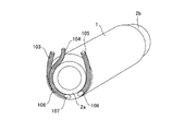
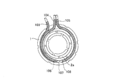
図3に従来の例えはバッテリで駆動するフォークリフト用の電動機のような低電圧で駆動する電動機のリード線引き出し構造を示す。図3に示すように、リード線103,104,105は、ステータ鉄心1の両端から突出したコイルエンド2a,2bのうち、一方側、図3ではコイルエンド2aのみから延びて一方向(図3では上方)に引き出される構成となっている。低電圧で駆動する電動機においては、使用する電流が大きくなるためにリード線103,104,105が太く構成されている。
FIG. 3 shows a lead wire lead-out structure of a motor driven by a low voltage such as a conventional forklift motor driven by a battery. As shown in FIG. 3, the
三相のコイルとリード線103,104,105との接続部106,107,108はコイルエンド2aの下方に互いに間隔をおいて配置されている。リード線103,104はそれぞれ接続部106,107から時計回りに上方へ向かって引き出され、リード線105は接続部108から反時計回りに上方へ向かって引き出されている。
しかしながら、上述した低電圧で駆動する電動機においては、図3に示すように太く形成されたリード線103,104を同一方向(図3では時計回り)へ引き出す構成となっているために、これらリード線103とリード線104とが互いに干渉しないように適度な空間を設ける必要があった。従って、従来の低電圧で駆動する電動機のリード線引き出し構造では装置が大型化する虞があるという問題があった。
However, the above-described electric motor driven at a low voltage has a configuration in which the
また、電動機側に端子台を設ける場合、太く形成されたリード線103,104,105の端子台への取り付け作業は、リード線103とリード線104が同一方向から延びているために作業スペースが狭くなるという問題、さらに、リード線103,104が太いために、狭いスペースで同一方向から延びる二本のリード線103,104をそれぞれ湾曲させて端子台へ取付ける作業は煩雑であり作業効率の低下につながる虞があった。
In addition, when the terminal block is provided on the motor side, the work of attaching the
このようなことから本発明は、リード線同士の干渉を防ぐための空間を設ける必要がなく、簡素な構造で端子台への取付作業を容易に行うことが可能な低電圧で駆動する電動機のリード線引き出し構造を提供することを特徴とする。 For this reason, the present invention does not require a space for preventing the interference between the lead wires, and the electric motor driven at a low voltage that can be easily attached to the terminal block with a simple structure. A lead wire drawing structure is provided.
上記の課題を解決するための本発明の請求項1に係る電動機のリード線引き出し構造は、低電圧で駆動する電動機のリード線引き出し構造であって、ステータ鉄心の両側に位置するコイルエンドのうち、一方のコイルエンド側で一相のコイルとリード線とを接続すると共に、前記一方のコイルエンドとは反対側に位置する他方のコイルエンド側で前記一相のコイルとは異なる二相のコイルとリード線とをそれぞれ接続し、前記他方のコイルエンド側で接続される二本の前記リード線はそれぞれ前記コイルとの接続部から互いに周方向に異なる方向へ向かって引き出されることを特徴とする。なお、ここでいう「周方向」とは、電動機の回転軸の軸周方向である。
In order to solve the above problems, a lead wire pulling structure for an electric motor according to
上述した本発明に係る電動機のリード線引き出し構造によれば、低電圧で駆動する電動機において、ステータ鉄心の両側に位置するコイルエンドのうち、一方のコイルエンド側で一相のコイルとリード線とを接続し、他方のコイルエンド側で残りの二相のコイルとリード線とをそれぞれ接続する構成、即ち、コイルとリード線との接続部を負荷側と反負荷側とに分けて設ける構成とすると共に、コイルとリード線との接続部が二箇所設けられるコイルエンド側にあっては、リード線を引き出す際にそれぞれのリード線を周方向に異なる方向へ向かって引き出す構成としたことにより、リード線同士が干渉する虞がなく、従来のようなリード線の干渉を避けるために設けていた空間が不要となる。 According to the lead wire lead-out structure of the electric motor according to the present invention described above, in the electric motor driven at a low voltage, among the coil ends located on both sides of the stator iron core, the one-phase coil and the lead wire are arranged on one coil end side. And connecting the remaining two-phase coil and the lead wire on the other coil end side, that is, a configuration in which the connection portion between the coil and the lead wire is divided into a load side and an anti-load side. In addition, on the coil end side where the connection portion between the coil and the lead wire is provided at two places, when the lead wire is drawn out, each lead wire is drawn out in a different direction in the circumferential direction, There is no possibility that the lead wires interfere with each other, and the space provided for avoiding the interference of the lead wires as in the prior art becomes unnecessary.
また、電動機側に端子台を設け、太く形成されたリード線を端子台へ取り付ける場合、二本のリード線が同一方向から延びることがないために従来と比較して作業スペースに余裕ができ、端子台へ取付ける作業も容易に行うことが可能となり、作業性を向上させることが可能となった。 In addition, when a terminal block is provided on the motor side and a lead wire formed thick is attached to the terminal block, the two lead wires do not extend from the same direction, so there is room in the work space compared to the conventional case, The work of attaching to the terminal block can be easily performed, and the workability can be improved.
本発明の実施形態を以下に説明する。本実施形態は、バッテリで駆動するフォークリフト用などの低電圧で駆動する電動機のリード線引き出し構造であって、ステータ鉄心の両側に位置するコイルエンドのうち、一方のコイルエンド側、例えば反負荷側で三相のコイルのうち一相のコイルとリード線とを接続すると共に、他方のコイルエンド側、例えば負荷側で残りの二相のコイルとリード線とをそれぞれ接続し、負荷側でコイルと接続された二本のリード線を、互いに干渉しないようにコイルエンドの外周に沿って図示しない回転軸の周方向であって異なる向き、例えば一方のリード線は時計回りに、他方のリード線は反時計回りにそれぞれ引き出すものである。 Embodiments of the present invention will be described below. This embodiment is a lead wire drawing structure of a motor driven by a low voltage such as for a forklift driven by a battery, and one of coil ends located on both sides of a stator core, for example, an anti-load side In the three-phase coil, the one-phase coil and the lead wire are connected, and the remaining two-phase coil and the lead wire are connected on the other coil end side, for example, the load side, and the coil is connected on the load side. Two connected lead wires are arranged in different directions along the outer periphery of the coil end so as not to interfere with each other in the circumferential direction of the rotating shaft (not shown), for example, one lead wire is clockwise and the other lead wire is Each is drawn counterclockwise.
上述した本実施形態によれば、リード線同士の干渉を防ぐために空間を設ける必要がなく、簡素な構造で端子台への取付作業を容易に行うことが可能な低電圧で駆動する電動機のリード線引き出し構造を提供することが可能となる。 According to the above-described embodiment, it is not necessary to provide a space to prevent interference between the lead wires, and the lead of the motor driven at a low voltage that can be easily attached to the terminal block with a simple structure. It is possible to provide a line drawing structure.
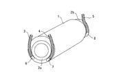
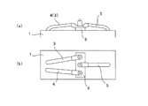
以下、本発明の一実施例を図に基づいて詳細に説明する。図1は本実施例における電動機のリード線引き出し構造を示す斜視図、図2(a)は端子台の設置例を示す側面図、図2(b)は端子台の設置例を示す上面図である。本実施例は低電圧で駆動する電動機のリード線引き出し構造に関するものである。 Hereinafter, an embodiment of the present invention will be described in detail with reference to the drawings. FIG. 1 is a perspective view showing a lead wire lead-out structure of an electric motor in this embodiment, FIG. 2A is a side view showing an installation example of a terminal block, and FIG. 2B is a top view showing an installation example of a terminal block. is there. The present embodiment relates to a lead wire drawing structure of an electric motor driven at a low voltage.
図1に示すように、ステータ鉄心1の両側に位置するコイルエンド2a及びコイルエンド2bから、リード線3,4,5が延びている。具体的には、コイルエンド2a側でリード線3,4と二相のコイルとがそれぞれ接続され、コイルエンド2b側でリード線5と一相のコイルとが接続されている。
As shown in FIG. 1,
リード線3,4とコイルとが接続される接続部6,7は、コイルエンド2aの下方に互いに間隔をおいて設けられ、リード線3,4はコイルエンド2aの外周に沿って上方且つ互いに離反する方向へ周方向に延びている。例えば、接続部6がコイルエンド2a下方であって左側、接続部7がコイルエンド2b下方であって右側に設けられている場合、リード線3は時計回りに、リード線4は反時計回りにコイルエンド2aの外周に沿って引き出されるものとする。
The connecting
リード線5とコイルとの接続部8はコイルエンド2bの下方に設けられ、リード線5はコイルエンド2bの外周に沿って周方向に上方へ向かって延びている。
The connecting
さらに、端子台9は例えばステータ鉄心1及びコイル等を覆うフレーム10の長手方向中央部に設けられ、リード線3,4と、リード線5とが、一方(例えば、リード線3,4)は端子台9の負荷側に取り付けられ、他方(例えば、リード線5)は端子台9の反負荷側に取付けられる構成となっている。
Further, the
上述した本実施例に係る電動機のリード線引き出し構造によれば、低電圧で駆動する電動機において、リード線3,4とコイルとの接続部6,7を反負荷側に設け、リード線5とコイルとの接続部8を負荷側に設けるというように、リード線3,4,5とコイルとの接続部6,7,8を、コイルエンド2a側とコイルエンド2b側とに分けて設ける構成とし、さらに、コイルエンド2a側から延びるリード線3,4を同一方向、例えば上方へ引き出す際、リード線3は時計回り、リード線4は反時計回りというようにそれぞれを互いに干渉しない方向へと延ばす構成としたことにより、リード線同士の干渉を防止できるために空間を設ける等の必要がなくなった。
According to the lead wire lead-out structure of the electric motor according to this embodiment described above, in the electric motor driven at a low voltage, the connecting
さらに、二本のリード線3,4と、一本のリード線5とを異なる方向から引き出す構成としたことにより、リード線3,4,5を端子台9に取付ける際に三本のリード線を同方向から取付ける必要がないために、取付け作業が容易であり、作業効率を向上させることが可能となった。
Further, since the two
また、電動機に端子台を2箇所設ける場合には、二本のリード線3,4は反負荷側に設けられた端子台に、一本のリード線5は負荷側に設けられた端子台にそれぞれ取り付けることとなり、狭いスペースの中で三本のリード線3,4,5を取付ける必要がないため、端子台へのリード線3,4,5の取付の際の作業性を向上させることができる。
When two terminal blocks are provided on the electric motor, the two
なお、上述した実施例は本発明の一形態であり、本発明の主旨を逸脱しない範囲内で種々の変更を行い得ることは言うまでもない。例えば、三相のコイルに対して、一相(例えば、U相)のコイルを負荷側のコイルエンドでリード線と接続した場合は、残りの二相(例えば、V相及びW相)のコイルは反負荷側のコイルエンドで二本のリード線とそれぞれ接続する、また、一相(例えば、U相)のコイルを反負荷側のコイルエンドでリード線と接続した場合は、残りの二相(例えば、V相及びW相)のコイルは負荷側のコイルエンドで二本のリード線とそれぞれ接続するというように、コイルとリード線との接続部を、負荷側と反負荷側とに分けて設ける構成であれば良い。 Note that the above-described embodiment is a form of the present invention, and it goes without saying that various modifications can be made without departing from the gist of the present invention. For example, when one phase (for example, U phase) coil is connected to the lead wire at the load side coil end with respect to the three phase coil, the remaining two phases (for example, V phase and W phase) coils Is connected to the two lead wires at the coil end on the anti-load side, and when the one-phase (for example, U phase) coil is connected to the lead wire at the coil end on the anti-load side, the remaining two phases (For example, the V-phase and W-phase coils are connected to two lead wires at the coil end on the load side, and the connection portion between the coil and the lead wire is divided into the load side and the anti-load side. Any configuration may be used.
そして、二本のリード線が引き出されるコイルエンドにおいては、それぞれのリード線を異なる方向へ延ばしてリード線が互いに干渉することがないようにすれば良い。 Then, in the coil end from which the two lead wires are drawn out, the respective lead wires may be extended in different directions so that the lead wires do not interfere with each other.
本発明は、低電圧で駆動する電動機のリード線引き出し構造に利用可能である。 INDUSTRIAL APPLICABILITY The present invention can be used for a lead wire drawing structure of an electric motor driven at a low voltage.
1 ステータ鉄心
2 コイルエンド
3,4,5 リード線
6,7,8 接続部
9 端子台
1 Stator core 2
Claims (1)
Priority Applications (1)
| Application Number | Priority Date | Filing Date | Title |
|---|---|---|---|
| JP2006180695A JP2008011663A (en) | 2006-06-30 | 2006-06-30 | Lead wire drawing-out structure for motor |
Applications Claiming Priority (1)
| Application Number | Priority Date | Filing Date | Title |
|---|---|---|---|
| JP2006180695A JP2008011663A (en) | 2006-06-30 | 2006-06-30 | Lead wire drawing-out structure for motor |
Publications (1)
| Publication Number | Publication Date |
|---|---|
| JP2008011663A true JP2008011663A (en) | 2008-01-17 |
Family
ID=39069330
Family Applications (1)
| Application Number | Title | Priority Date | Filing Date |
|---|---|---|---|
| JP2006180695A Withdrawn JP2008011663A (en) | 2006-06-30 | 2006-06-30 | Lead wire drawing-out structure for motor |
Country Status (1)
| Country | Link |
|---|---|
| JP (1) | JP2008011663A (en) |
Cited By (4)
| Publication number | Priority date | Publication date | Assignee | Title |
|---|---|---|---|---|
| WO2010091953A2 (en) | 2009-02-13 | 2010-08-19 | BSH Bosch und Siemens Hausgeräte GmbH | Refrigerator with internal lighting |
| CN101986521A (en) * | 2010-06-30 | 2011-03-16 | 苏州贝得科技有限公司 | Winding lead-out terminal block for high-voltage refrigerating motor |
| JP2013158144A (en) * | 2012-01-30 | 2013-08-15 | Mitsuba Corp | Insulator and rotary electric machine |
| WO2023207335A1 (en) * | 2022-04-24 | 2023-11-02 | 浙江盾安人工环境股份有限公司 | Coil assembly and electronic expansion valve having same |
-
2006
- 2006-06-30 JP JP2006180695A patent/JP2008011663A/en not_active Withdrawn
Cited By (4)
| Publication number | Priority date | Publication date | Assignee | Title |
|---|---|---|---|---|
| WO2010091953A2 (en) | 2009-02-13 | 2010-08-19 | BSH Bosch und Siemens Hausgeräte GmbH | Refrigerator with internal lighting |
| CN101986521A (en) * | 2010-06-30 | 2011-03-16 | 苏州贝得科技有限公司 | Winding lead-out terminal block for high-voltage refrigerating motor |
| JP2013158144A (en) * | 2012-01-30 | 2013-08-15 | Mitsuba Corp | Insulator and rotary electric machine |
| WO2023207335A1 (en) * | 2022-04-24 | 2023-11-02 | 浙江盾安人工环境股份有限公司 | Coil assembly and electronic expansion valve having same |
Similar Documents
| Publication | Publication Date | Title |
|---|---|---|
| JP6336193B2 (en) | Permanent magnet type three-phase duplex motor and electric power steering device | |
| JP6068953B2 (en) | Electric motor | |
| JP5741747B1 (en) | Insulator and brushless DC motor using the same | |
| EP2940834B1 (en) | Motor | |
| EP3200318A1 (en) | Brushless motor | |
| JP2009213286A (en) | Brushless motor | |
| JP2011166896A (en) | Motor | |
| JP2007068369A (en) | Motor connection structure | |
| CN100495861C (en) | Stator of motor | |
| JP2013223293A5 (en) | ||
| CN105359383B (en) | Magnet scattering prevention and holding structure of rotating electric machine | |
| JP6337132B2 (en) | Rotating electric machine stator and rotating electric machine equipped with the same | |
| JP2007174869A (en) | Insulator, stator assembly, segment stator, and stator for rotating electrical machine | |
| JP2016101031A (en) | Stator for three-phase motor | |
| JP2009044869A (en) | Rotary electric machine | |
| JP2008011663A (en) | Lead wire drawing-out structure for motor | |
| JP2014054104A (en) | Attachment structure of lead wire terminal | |
| JP4857615B2 (en) | Coil connection structure of rotating electrical machine | |
| JP4956774B2 (en) | Wiring structure of axial gap type motor | |
| JP2012244839A (en) | Stator for rotating electric machine | |
| JP2014108029A (en) | Rotary electric machine simplifying bus bar structure by continuous winding | |
| CN102738997A (en) | Direct current motor and winding package method | |
| JP6004708B2 (en) | Three-phase AC motor and electric compressor provided with the same | |
| JP2005006487A (en) | Three-phase motor | |
| JP2009303286A (en) | Electric motor |
Legal Events
| Date | Code | Title | Description |
|---|---|---|---|
| A300 | Withdrawal of application because of no request for examination |
Free format text: JAPANESE INTERMEDIATE CODE: A300 Effective date: 20090901 |