JP5946582B2 - Male element - Google Patents
Male element Download PDFInfo
- Publication number
- JP5946582B2 JP5946582B2 JP2015501037A JP2015501037A JP5946582B2 JP 5946582 B2 JP5946582 B2 JP 5946582B2 JP 2015501037 A JP2015501037 A JP 2015501037A JP 2015501037 A JP2015501037 A JP 2015501037A JP 5946582 B2 JP5946582 B2 JP 5946582B2
- Authority
- JP
- Japan
- Prior art keywords
- component
- male element
- element according
- longitudinal axis
- channel
- Prior art date
- Legal status (The legal status is an assumption and is not a legal conclusion. Google has not performed a legal analysis and makes no representation as to the accuracy of the status listed.)
- Active
Links
Images


Classifications
-
- B—PERFORMING OPERATIONS; TRANSPORTING
- B29—WORKING OF PLASTICS; WORKING OF SUBSTANCES IN A PLASTIC STATE IN GENERAL
- B29C—SHAPING OR JOINING OF PLASTICS; SHAPING OF MATERIAL IN A PLASTIC STATE, NOT OTHERWISE PROVIDED FOR; AFTER-TREATMENT OF THE SHAPED PRODUCTS, e.g. REPAIRING
- B29C33/00—Moulds or cores; Details thereof or accessories therefor
- B29C33/02—Moulds or cores; Details thereof or accessories therefor with incorporated heating or cooling means
- B29C33/04—Moulds or cores; Details thereof or accessories therefor with incorporated heating or cooling means using liquids, gas or steam
-
- B—PERFORMING OPERATIONS; TRANSPORTING
- B29—WORKING OF PLASTICS; WORKING OF SUBSTANCES IN A PLASTIC STATE IN GENERAL
- B29C—SHAPING OR JOINING OF PLASTICS; SHAPING OF MATERIAL IN A PLASTIC STATE, NOT OTHERWISE PROVIDED FOR; AFTER-TREATMENT OF THE SHAPED PRODUCTS, e.g. REPAIRING
- B29C43/00—Compression moulding, i.e. applying external pressure to flow the moulding material; Apparatus therefor
- B29C43/32—Component parts, details or accessories; Auxiliary operations
- B29C43/52—Heating or cooling
-
- B—PERFORMING OPERATIONS; TRANSPORTING
- B29—WORKING OF PLASTICS; WORKING OF SUBSTANCES IN A PLASTIC STATE IN GENERAL
- B29C—SHAPING OR JOINING OF PLASTICS; SHAPING OF MATERIAL IN A PLASTIC STATE, NOT OTHERWISE PROVIDED FOR; AFTER-TREATMENT OF THE SHAPED PRODUCTS, e.g. REPAIRING
- B29C45/00—Injection moulding, i.e. forcing the required volume of moulding material through a nozzle into a closed mould; Apparatus therefor
- B29C45/17—Component parts, details or accessories; Auxiliary operations
- B29C45/72—Heating or cooling
- B29C45/73—Heating or cooling of the mould
- B29C45/7312—Construction of heating or cooling fluid flow channels
- B29C2045/7318—Construction of heating or cooling fluid flow channels multilayered fluid channel constructions
-
- B—PERFORMING OPERATIONS; TRANSPORTING
- B29—WORKING OF PLASTICS; WORKING OF SUBSTANCES IN A PLASTIC STATE IN GENERAL
- B29C—SHAPING OR JOINING OF PLASTICS; SHAPING OF MATERIAL IN A PLASTIC STATE, NOT OTHERWISE PROVIDED FOR; AFTER-TREATMENT OF THE SHAPED PRODUCTS, e.g. REPAIRING
- B29C45/00—Injection moulding, i.e. forcing the required volume of moulding material through a nozzle into a closed mould; Apparatus therefor
- B29C45/17—Component parts, details or accessories; Auxiliary operations
- B29C45/72—Heating or cooling
- B29C45/73—Heating or cooling of the mould
- B29C2045/7362—Heating or cooling of the mould turbulent flow of heating or cooling fluid
-
- B—PERFORMING OPERATIONS; TRANSPORTING
- B29—WORKING OF PLASTICS; WORKING OF SUBSTANCES IN A PLASTIC STATE IN GENERAL
- B29C—SHAPING OR JOINING OF PLASTICS; SHAPING OF MATERIAL IN A PLASTIC STATE, NOT OTHERWISE PROVIDED FOR; AFTER-TREATMENT OF THE SHAPED PRODUCTS, e.g. REPAIRING
- B29C33/00—Moulds or cores; Details thereof or accessories therefor
- B29C33/02—Moulds or cores; Details thereof or accessories therefor with incorporated heating or cooling means
- B29C33/04—Moulds or cores; Details thereof or accessories therefor with incorporated heating or cooling means using liquids, gas or steam
- B29C33/048—Moulds or cores; Details thereof or accessories therefor with incorporated heating or cooling means using liquids, gas or steam using steam
-
- B—PERFORMING OPERATIONS; TRANSPORTING
- B29—WORKING OF PLASTICS; WORKING OF SUBSTANCES IN A PLASTIC STATE IN GENERAL
- B29K—INDEXING SCHEME ASSOCIATED WITH SUBCLASSES B29B, B29C OR B29D, RELATING TO MOULDING MATERIALS OR TO MATERIALS FOR MOULDS, REINFORCEMENTS, FILLERS OR PREFORMED PARTS, e.g. INSERTS
- B29K2105/00—Condition, form or state of moulded material or of the material to be shaped
- B29K2105/25—Solid
- B29K2105/253—Preform
-
- B—PERFORMING OPERATIONS; TRANSPORTING
- B29—WORKING OF PLASTICS; WORKING OF SUBSTANCES IN A PLASTIC STATE IN GENERAL
- B29L—INDEXING SCHEME ASSOCIATED WITH SUBCLASS B29C, RELATING TO PARTICULAR ARTICLES
- B29L2031/00—Other particular articles
- B29L2031/56—Stoppers or lids for bottles, jars, or the like, e.g. closures
- B29L2031/565—Stoppers or lids for bottles, jars, or the like, e.g. closures for containers
Description
本発明は、ポリマー材料で形成される物体の射出成形又は圧縮成形に使用することができる雄型素子に関する。本発明による雄型素子は、とくに、中空物体、例えば容器のキャップ、又は容器のプリフォーム(予備成形品)、及びとくに、ボトル若しくは容器のプリフォームの内面を造形するのに使用できる。本発明による雄型素子は、ほぼ平坦な物体、例えば、容器キャップ用のシールを造形するのにも使用できる。 The present invention relates to a male element that can be used for injection molding or compression molding of an object formed of a polymer material. The male element according to the invention can in particular be used for shaping hollow objects, such as container caps or container preforms, and in particular the inner surfaces of bottles or container preforms. The male element according to the invention can also be used to form a substantially flat object, for example a seal for a container cap.
特許文献1(国際公開第2007/028702号パンフレット)は、内側から容器キャップを造形する雄型素子を記載している。この特許文献1に記載されている雄型素子は、中心コア及びこの中心コアの外側に配置した管状コンポーネントを有する。冷却回路を中心コア及び管状コンポーネントの双方に装備し、冷却流体が中心コアから管状コンポーネントに向けて流れ、また管状コンポーネントから中心コアに帰還できるようにする。
Patent Document 1 (International Publication No. 2007/028702 pamphlet) describes a male element that forms a container cap from the inside. The male element described in
特許文献1に記載の冷却回路は極めて効率的であり、なぜなら冷却流体は、キャップを形成する各表面近傍で中心コア内及び管状コンポーネント内双方に送給できるからである。しかし、特許文献1に記載の雄型素子は、特別な技術、いわゆる「金属射出成形(MIM:metal injection moulding)」を構築する必要がある。さらに、管状コンポーネントは、中心コアに対して移動可能であるため、管状コンポーネントと中心コアとの間に摺動シールを介在させる必要があり、この摺動シールは急激に摩耗を生じ、頻繁に交換しなければならない。
The cooling circuit described in U.S. Pat. No. 6,053,836 is extremely efficient because cooling fluid can be delivered both within the central core and within the tubular component near each surface forming the cap. However, the male element described in
特許文献2(独国特許公開第10022289号)は、摺動シールに関連する欠点を制限する雄型素子を記載している。実際、特許文献2に記載の雄型素子は、中心コアを冷却する第1冷却回路、中心コアの周りに配置したエジェクタを冷却する第2冷却回路、及びエジェクタの周りに配置した回転可能コンポーネントを冷却する第3冷却回路を有することに特徴がある。しかし、特許文献2は、第2冷却回路及び第3冷却回路の構成に関する詳細な情報がない。
Patent document 2 (DE 10022289) describes a male element that limits the disadvantages associated with sliding seals. In fact, the male element described in
本発明の目的の1つは、ポリマー材料で圧縮成形又は射出成形により形成する物体を得る改良した雄型素子を提供するにある。 One of the objects of the present invention is to provide an improved male element for obtaining an object formed from a polymer material by compression molding or injection molding.
本発明の他の目的は、高効率冷却システムを装備した雄型素子を得るにある。 Another object of the present invention is to obtain a male element equipped with a high efficiency cooling system.
別の目的は、効率よく冷却でき、同時に簡単に生産及び組立できる雄型素子を得るにある。 Another object is to obtain a male element that can be efficiently cooled and at the same time easily produced and assembled.
さらに他の目的は、効率よく冷却でき、急激な摩耗を受けるコンポーネントの数を減少できる雄型素子を得るにある。 Yet another object is to provide a male element that can be efficiently cooled and that can reduce the number of components subject to rapid wear.
本発明の第1の態様において、雄型素子であって、前記雄型素子の第1コンポーネントに設けた第1通路手段と、前記雄型素子の第2コンポーネントに設けた第2通路手段とを有する冷却回路を備える雄型素子を提供し、前記第1通路手段及び前記第2通路手段は、前記雄型素子の長手方向軸線の周りに分布させ、前記第1通路手段が前記第2通路手段に流体連通する、前記第2コンポーネントに対する前記第1コンポーネントの複数の角度位置が存在するよう構成する、該雄型素子において、前記第2コンポーネントを前記第1コンポーネントに着脱可能連結によって固着し、この固着は、前記雄型素子の動作中に前記第2コンポーネントが前記第1コンポーネントに対して回転不能に取付けるように行うことを特徴とする。 In the first aspect of the present invention, a male element, the first passage means provided in the first component of the male element, and the second passage means provided in the second component of the male element, And a first passage means and a second passage means are distributed around a longitudinal axis of the male element, the first passage means being the second passage means. A plurality of angular positions of the first component relative to the second component in fluid communication with the male component, wherein the second component is secured to the first component by a detachable connection; The fixing is performed such that the second component is non-rotatably attached to the first component during operation of the male element.
第1通路手段は、第1コンポーネントの第2コンポーネントに対する複数個の角度位置で第2通路手段と連通するので、冷却流体が第1コンポーネントから第2コンポーネントに又はその逆に流れるのを確実にし、しかも第2コンポーネントを第1コンポーネントに対して所定の角度位置に位置決めすることを目的とするタイミングシステムを使用することなく、第2コンポーネントを第1コンポーネントに取付けることができる。 The first passage means communicates with the second passage means at a plurality of angular positions of the first component relative to the second component, thus ensuring that cooling fluid flows from the first component to the second component or vice versa, Moreover, the second component can be attached to the first component without using a timing system that is intended to position the second component at a predetermined angular position relative to the first component.
このことにより、例えば、クリーニング作業又はメンテナンス作業を実施するために第1コンポーネントを第2コンポーネントから分離し、次に再び互いに組立てる着脱可能連結の利用を可能にし、またこの利用を容易にする。組立て後、第1コンポーネント及び第2コンポーネントは、一方を他方に対して回転することなく単一ピースのように挙動する。 This allows and facilitates the use of a detachable connection that, for example, separates the first component from the second component and then reassembles them to perform a cleaning or maintenance operation. After assembly, the first component and the second component behave like a single piece without rotating one with respect to the other.
本発明の第2の態様において、長手方向軸線に沿って延在する雄型素子を提供し、この雄型素子は、雄型素子の第1コンポーネントに設けた第1通路手段及び雄型素子の第2コンポーネントに設けた第2通路手段を有する冷却回路を備え、前記第1通路手段及び前記第2通路手段は、前記雄型素子の長手方向軸線の周りに分布させ、前記第1通路手段が前記第2通路手段に流体連通する、前記第2コンポーネントに対する前記第1コンポーネントの複数の角度位置が存在するよう構成することを特徴とする。 In a second aspect of the invention, a male element is provided that extends along a longitudinal axis, the male element comprising first passage means provided in a first component of the male element and the male element. A cooling circuit having a second passage means provided in a second component, wherein the first passage means and the second passage means are distributed around a longitudinal axis of the male element; A plurality of angular positions of the first component relative to the second component in fluid communication with the second passage means are present.
冷却回路によって、所望の物体を形成する雄型素子の表面を効果的に冷却することができる。さらに、第1コンポーネントの第2コンポーネントに対する複数の角度位置で第1通路手段が第2通路手段に対して流体連通するので、複雑なタイミングシステムを設けること、又は幾何学的若しくは寸法上の狭い公差は不要になり、第2コンポーネントを第1コンポーネントに対して所定角度位置に常に取付けることを確実にできる。このことは、本発明による雄型素子の組立てをとくに簡単にする。 The cooling circuit can effectively cool the surface of the male element that forms the desired object. Further, since the first passage means is in fluid communication with the second passage means at a plurality of angular positions of the first component relative to the second component, a complex timing system can be provided, or a narrow geometric or dimensional tolerance. Is no longer necessary and it can be ensured that the second component is always mounted at a predetermined angular position relative to the first component. This makes the assembly of the male element according to the invention particularly simple.
表現「第1コンポーネントの第2コンポーネントに対する角度位置」は、雄型素子を得るよう第1コンポーネント及び第2コンポーネントを組立てている間に理論的に画定される位置を意味する。とくに、上述の角度位置は、長手方向軸線周りに第1コンポーネントを第2コンポーネントに対して回転することによって、又は第2コンポーネントを第1コンポーネントに対して回転することによって画定することができる。換言すれば、第1コンポーネントの第2コンポーネントに対する長手方向軸線周りの角度位置の問題である。 The expression “angular position of the first component relative to the second component” means a position that is theoretically defined while assembling the first and second components to obtain a male element. In particular, the angular position described above can be defined by rotating the first component relative to the second component about the longitudinal axis or by rotating the second component relative to the first component. In other words, the problem is the angular position about the longitudinal axis of the first component relative to the second component.
この角度位置は、例えば、雄型素子の組立て作業中に画定することができる。このことは、第1コンポーネントを第2コンポーネントに回転可能に取付けること、すなわち、雄型素子の動作中に第1コンポーネントが第2コンポーネントに対して回転できることを意味しない。 This angular position can be defined, for example, during the assembly of the male element. This does not mean that the first component is rotatably mounted on the second component, i.e. the first component can rotate relative to the second component during operation of the male element.
一実施形態において、第2コンポーネントを第1コンポーネントに対して長手方向軸線周りに回転する場合でも、第1通路手段は第2通路手段に流体連通する。とくに、第2コンポーネントを第1コンポーネントに対して長手方向軸線周りに回転する場合でも、第1通路手段は第2通路手段に対面する。 In one embodiment, the first passage means is in fluid communication with the second passage means even when the second component is rotated about the longitudinal axis relative to the first component. In particular, the first passage means faces the second passage means even when the second component rotates about the longitudinal axis relative to the first component.
このようにして、冷却回路を循環する冷却流体は、たとえ第2コンポーネントが長手方向軸線周りに第1コンポーネントに対して回転するとしても、第1通路手段から第2通路手段に流れ、またその逆に流れる。 In this way, the cooling fluid circulating in the cooling circuit flows from the first passage means to the second passage means and vice versa, even though the second component rotates relative to the first component about the longitudinal axis. Flowing into.
一実施形態において、第1通路手段は少なくとも第1通路を有し、また第2通路手段は少なくとも第2通路を有し、第1通路及び第2通路は、それぞれ第1コンポーネントと第2コンポーネントとの間における境界ゾーンで角度寸法を有する。第1通路の角度寸法は、第2通路の角度寸法よりも大きいものとする。このようにして、第2通路は、第1コンポーネントが所定限界範囲内で第2コンポーネントに対して回転する、又はその逆の回転をするにしても、第2通路の角度範囲全体に沿って第1通路に対面するのを維持する。このことは、第1コンポーネント及び第2コンポーネントの複数の相対角度位置において、第1通路手段と第2通路手段との間に流体連通が存在するのを確実にする。 In one embodiment, the first passage means comprises at least a first passage, and the second passage means comprises at least a second passage, the first passage and the second passage comprising a first component and a second component, respectively. With an angular dimension in the boundary zone between. The angular dimension of the first passage is assumed to be larger than the angular dimension of the second passage. In this way, the second passageway is configured along the entire angular range of the second passageway, even if the first component rotates relative to the second component within the predetermined limit range or vice versa. Maintain facing one passage. This ensures that fluid communication exists between the first passage means and the second passage means at a plurality of relative angular positions of the first component and the second component.
一実施形態において、第1通路手段は少なくとも1個の窪みを有し、第2通路手段は複数個のチャネルを有し、隣接する2個のチャネル間における距離及び各チャネルの幅は、第2コンポーネントが長手方向軸線周りに第1コンポーネントに対して回転しても、少なくとも1個のチャネルが少なくとも1個の窪みに対面するような寸法にする。 In one embodiment, the first passage means has at least one indentation, the second passage means has a plurality of channels, and the distance between two adjacent channels and the width of each channel is a second value. The component is dimensioned such that at least one channel faces at least one recess as the component rotates about the longitudinal axis relative to the first component.
このように構成した第1通路手段及び第2通路手段は実現するのが簡単であり、なぜなら、それら通路手段は、複雑な技術、例えば、金属射出成形(MIM:metal injection moulding)に頼ることなく、単純なフライス削り又は穴開け作業によって得られるからである。 The first passage means and the second passage means configured in this way are simple to implement because they do not rely on complex techniques such as metal injection molding (MIM). This is because it can be obtained by simple milling or drilling operations.
一実施形態において、第1コンポーネント及び第2コンポーネントは、組立てた形態では雄型素子の管状形成部材を画定する。したがって、冷却回路は管状形成部材内に装備される。 In one embodiment, the first component and the second component define a tubular forming member of the male element in the assembled form. Accordingly, the cooling circuit is provided in the tubular forming member.
雄型素子は、さらに、管状形成部材内に配置する中心形成コアを備える。一実施形態において、雄型素子は、さらに、中心形成コアを冷却する他の冷却回路を備え、この他の冷却回路は管状形成部材内に設ける冷却回路とは独立している。 The male element further comprises a center forming core disposed within the tubular forming member. In one embodiment, the male element further comprises another cooling circuit that cools the center forming core, the other cooling circuit being independent of the cooling circuit provided in the tubular forming member.
このことにより、雄型素子はとくに効率よく冷却できるものとして得られ、なぜなら冷却回路及び他の冷却回路は、形成物体の周辺領域及び中心領域双方を冷却できるからである。 This gives the male element that it can be cooled particularly efficiently, because the cooling circuit and other cooling circuits can cool both the peripheral area and the central area of the formed object.
さらに、冷却回路は他の冷却回路とは独立しているため、中心形成コア及び管状形成部材が互いに相対移動する場合でも、摺動シールを使用する必要はない。このことにより、摩耗を受けるコンポーネントの使用を制限でき、またひいては雄型素子のメンテナンスを簡素化できるようになる。 Furthermore, since the cooling circuit is independent of other cooling circuits, it is not necessary to use a sliding seal even when the center forming core and the tubular forming member move relative to each other. This can limit the use of components that are subject to wear and thus simplify the maintenance of the male element.
一実施形態において、第1通路手段は、第2コンポーネントが第1コンポーネントに接触する境界ゾーンで第2通路手段に対面する。 In one embodiment, the first passage means faces the second passage means at a boundary zone where the second component contacts the first component.
境界ゾーンは長手方向軸線周りに延在することができる。 The boundary zone can extend around the longitudinal axis.
代案として、境界ゾーンは、長手方向軸線に交差する、とくに、長手方向軸線に直交する方向に延在する。 As an alternative, the boundary zone extends in a direction intersecting the longitudinal axis, in particular in a direction perpendicular to the longitudinal axis.
第1通路手段は送給窪み及び帰還窪みを有するとともに、第2通路手段は長手方向軸線周りに分布させた複数個のチャネルを有する。 The first passage means has a feed well and a return well, and the second passage means has a plurality of channels distributed about the longitudinal axis.
一実施形態において、1対の分離面を送給窪みと帰還窪みとの間に介在させ、各分離面は第2コンポーネントの表面部分に接触し、送給窪みを帰還窪みから隔絶する。 In one embodiment, a pair of separation surfaces are interposed between the feed and return wells, with each separation surface contacting the surface portion of the second component and isolating the feed well from the return well.
とくに、複数個のチャネルのうち、少なくとも1個のチャネルは送給窪みに対面し、複数個のチャネルのうち、少なくとも1個のチャネルは帰還窪みに対面し、また複数個のチャネルのうち、少なくとも1個のチャネルは各分離面に対面する。 In particular, at least one channel of the plurality of channels faces the feed well, at least one channel of the plurality of channels faces the return well, and at least one of the plurality of channels. One channel faces each separation surface.
送給窪み及び帰還窪みは、第1コンポーネントの内面に設けるとともに、複数個のチャネルは、第2コンポーネントの外面に設ける。 The feed recess and the return recess are provided on the inner surface of the first component, and the plurality of channels are provided on the outer surface of the second component.
管状形成部材は第2コンポーネントに同軸状の第3コンポーネントを有する。 The tubular forming member has a third component that is coaxial with the second component.
一実施形態において、複数個のチャネルは、第1コンポーネントから突出する第2コンポーネントの領域に沿って連続し、第3コンポーネントの側面が前記領域におけるチャネルに対面して、チャネルを閉じ、また対応の導管を画定する。 In one embodiment, the plurality of channels are continuous along a region of the second component protruding from the first component, the side of the third component faces the channel in the region, closes the channel, and A conduit is defined.
冷却回路は、送給窪み及び帰還窪みの双方に対して複数個のチャネルを介して連通する環状導管として形成するのが好ましい連通導管を有し、連通導管を前記形成表面の近傍に配置する。 The cooling circuit has a communication conduit that is preferably formed as an annular conduit that communicates with both the feed and return recesses through a plurality of channels, and the communication conduit is located near the forming surface.
とくに、連通導管は、第2コンポーネントと第3コンポーネントとの間に画定する。 In particular, the communication conduit is defined between the second component and the third component.
一実施形態において、雄型素子は、さらに、中心形成コアと管状形成部材との間の相対移動を生じさせ、中心形成コアと管状形成部材との間に形成したアンダーカット部分を離脱させる、移動装置を備える。 In one embodiment, the male element further causes a relative movement between the center forming core and the tubular forming member and disengages an undercut portion formed between the center forming core and the tubular forming member. Equipment.
一実施形態において、第2コンポーネントは第1コンポーネントに着脱可能に固着し、とくに、第1コンポーネントにねじ付ける。 In one embodiment, the second component is removably secured to the first component, in particular screwed to the first component.
本発明の第3態様において、物体を形成する雄型素子を提供し、本発明雄型素子は、物体の部分を冷却する冷却回路と、物体の他の部分を冷却する他の冷却回路を備え、他の冷却回路は冷却回路とは独立しており、冷却回路は、環状導管と、冷却流体を環状導管に送給するよう雄型素子に長手方向に延在する流入路手段と、環状導管から冷却流体を排出するよう雄型素子に長手方向に延在する流出路手段とを有することを特徴とする。 In a third aspect of the invention, a male element for forming an object is provided, the male element of the invention comprising a cooling circuit for cooling a part of the object and another cooling circuit for cooling another part of the object. The other cooling circuit is independent of the cooling circuit, the cooling circuit including an annular conduit, an inflow channel means extending longitudinally to the male element to deliver cooling fluid to the annular conduit, and the annular conduit And an outflow passage means extending in the longitudinal direction in the male element so as to discharge the cooling fluid therefrom.
本発明のこの態様により、効果的に冷却でき、また同時に構成及び組立てが簡単な雄型素子を得ることができる。 This aspect of the invention provides a male element that can be effectively cooled and at the same time is simple to construct and assemble.
互いに独立した冷却回路及び他の冷却回路によれば、実際形成した物体の明確に異なる部分を冷却でき、たとえこのような部分が、雄型素子の互いに相対移動するパーツによって造形されるものであっても、冷却できる。 Independent cooling circuits and other cooling circuits can cool distinctly different parts of the actually formed object, even if such parts are shaped by parts of the male element that move relative to each other. But it can be cooled.
雄型素子において長手方向に延在する流入路手段及び流出路手段は、MIM技術のような複雑な技術に頼ることなく、普通の工作機械加工技術により形成することができる。 The inflow path means and the outflow path means extending in the longitudinal direction in the male element can be formed by ordinary machine tool machining techniques without resorting to complicated techniques such as the MIM technique.
さらに、環状導管は、従来技術で見られる複雑な螺旋導管に比べると構成が一層簡単である。 Furthermore, the annular conduit is simpler to construct than the complex helical conduit found in the prior art.
一実施形態において、雄型素子は長手方向軸線を有する。 In one embodiment, the male element has a longitudinal axis.
流入路手段は、長手方向軸線を中心とする円弧に沿って測り、少なくとも10゜の角度、好適には、30゜の角度より大きい角度寸法を有する。 The inlet channel means is measured along an arc centered on the longitudinal axis and has an angular dimension of at least an angle of 10 °, preferably greater than an angle of 30 °.
同様に、流出路手段は、長手方向軸線を中心とする円弧に沿って測り、少なくとも10゜の角度、好適には、30゜の角度より大きい角度寸法を有する。このようにして、流入路手段及び流出路手段は、雄型素子によって造形される物体を効果的に冷却する冷却流体の十分な流れを確保する。 Similarly, the outflow channel means is measured along an arc centered on the longitudinal axis and has an angular dimension of at least an angle of 10 °, preferably greater than an angle of 30 °. In this way, the inflow channel means and the outflow channel means ensure a sufficient flow of cooling fluid that effectively cools the object shaped by the male element.
本発明の第4態様において、ポリマー材料を成形することによって物体を形成するため、物体を冷却する冷却回路を備える雄型素子を提供し、本発明雄型素子は、さらに、物体と冷却回路との間に介在させたヒートパイプを備え、物体から熱を奪い、また熱を冷却回路に伝達する構成としたことを特徴とする。 In a fourth aspect of the present invention, there is provided a male element comprising a cooling circuit for cooling an object for forming an object by molding a polymer material, the male element of the present invention further comprising an object, a cooling circuit, A heat pipe interposed between the two is provided to take heat from the object and to transfer the heat to the cooling circuit.
ヒートパイプは、熱伝導材料、とくに金属で形成した閉鎖中空素子とし、内部に一部液相及び一部ガス相となる冷却材料を収納する。ヒートパイプは、内部に収納される液相が変化することによって熱を排除することができる。 The heat pipe is a closed hollow element made of a heat conductive material, particularly a metal, and contains therein a cooling material that becomes a part of liquid phase and part of gas phase. The heat pipe can exclude heat by changing the liquid phase housed therein.
ヒートパイプ内部に収納される液体が液相からガス相に遷移するとき、比較的多量の熱が成形した物体から奪われる。この熱量は、単に状態変化がない流体を加熱することにより奪われる熱量よりも大きい。 When the liquid stored inside the heat pipe transitions from the liquid phase to the gas phase, a relatively large amount of heat is taken away from the molded object. This amount of heat is greater than the amount of heat that is simply taken away by heating a fluid that does not change state.
さらに、ヒートパイプは密封されているので、成形した物体近傍で流体漏れのリスクが激減する。 Furthermore, since the heat pipe is sealed, the risk of fluid leakage near the molded object is greatly reduced.
さらに、適当な形状のヒートパイプを準備した後には、組立てが極めて簡単である。 Furthermore, the assembly is very simple after preparing a heat pipe of an appropriate shape.
一実施形態において、物体の一部分を形成するための形成表面をヒートパイプに設けることができる。この実施形態によれば、物体を特に効果的に冷却でき、なぜなら、物体を形成するポリマー材料にヒートパイプを直接接触するよう配置するからである。 In one embodiment, the heat pipe can be provided with a forming surface for forming a portion of the object. According to this embodiment, the object can be cooled particularly effectively because the heat pipe is arranged in direct contact with the polymer material forming the object.
一実施形態において、雄型素子は、ヒートパイプと物体との間に介在させるのに適した形成素子を有する。 In one embodiment, the male element has a forming element suitable for interposition between the heat pipe and the object.
このようにして、物体に付与するのが望ましい形状に従うようヒートパイプを形成できないような複雑な形状を有する物体を形成する必要があるときでさえも、ヒートパイプを使用できる。 In this way, heat pipes can be used even when it is necessary to form an object having a complex shape that cannot be formed to conform to the shape that it is desired to impart to the object.
本発明は、本発明を限定するものではない、幾つかの例示的実施形態を示す添付図面を参照することによって、よりよく理解し、また実施することができるであろう。 The present invention may be better understood and practiced by reference to the accompanying drawings that illustrate some exemplary embodiments that are not intended to limit the invention.
図1は、図2にも示す雄型素子2を備える成形ユニット1の一部を示す。
FIG. 1 shows a part of a
雄型素子2を使用してポリマー材料で射出成形又は圧縮成形により形成した物体5を得る。この物体5は、中空物体、例えばボトル用のキャップ、もっと一般的には容器用のキャップとすることができる。この場合、雄型素子2は、成形ユニット1に設ける図示しない雌型素子と協調動作する。
The
代案として、物体5は、ほぼ平坦な物体、例えば、ボトルキャップ又はもっと一般的には容器キャップのシールとすることができる。このシールは、予め形成したキャップ内で直接雄型素子2によって成形することができる。この場合、成形ユニット1は、雌型素子の代わりに、内側にシールを形成しなければならないキャップを支持する図示しない支持素子を備える。
Alternatively, the object 5 can be a substantially flat object, such as a bottle cap or more generally a container cap seal. This seal can be molded directly by the
成形ユニット1は、互いに同一の複数個の成形ユニット1を備える成形装置内に設けることができる。圧縮成形技術を使用する場合、成形ユニット1は、回転軸線、例えば垂直回転軸線周りに回転可能なカルーセルの周辺領域に取付けることができる。それに代わり、射出成形技術を使用する場合、成形ユニット1は、2次元的分布に従って互いに並置させて取付けることができる。
The
図2に示すように、雄型素子2は、長手方向軸線Zに沿って延在する中心形成コア3を有する。図示の実施形態において、長手方向軸線Zは垂直であるが、他の実施形態では長手方向軸線Zは水平又は傾斜しているものとすることもできる。中心形成コア3には、ポリマー材料に接触し、物体5の内面部分を形成する、例えば、図8に示すようにキャップ又はシールの底壁38を内側から形成する形成表面を設ける。
As shown in FIG. 2, the
雄型素子1は、さらに、中心形成コア3の外側に配置した、すなわち、中心形成コア3を包囲する管状形成部材4を有する。管状形成部材4には、同様に、ポリマー材料に接触して、物体5の表面を形成するのに適した形成表面を設ける。
The
とくに、中心形成コア3及び管状形成部材4は互いに協調動作して、物体5のアンダーカットを設ける部分を形成する。図示の実施形態において、物体5のアンダーカットを設ける部分は封止リップ39であり、この封止リップ39は、図8に示すように底面38から突出し、使用中に容器ネック部の内面に係合する。封止リップ39によれば、容器をほぼ密封することができる。
In particular, the center forming core 3 and the tubular forming member 4 cooperate with each other to form a portion in which the undercut of the object 5 is provided. In the illustrated embodiment, the part of the object 5 to be provided with an undercut is a sealing
中心形成コア3及び管状形成部材4は、成形サイクル中に互いに相対移動可能に取付ける。管状形成部材4を中心形成コア3に対して移動させることによって、又はその逆の相対移動をさせることによって、物体5のアンダーカットを設ける部分、すなわち、封止リップ39が雄型素子2から離脱することができる。
The center forming core 3 and the tubular forming member 4 are mounted so as to be movable relative to each other during the molding cycle. By moving the tubular forming member 4 with respect to the central forming core 3 or vice versa, the part in which the undercut of the object 5 is provided, ie the sealing
管状形成部材4は、管状形成部材4によって造形される物体5の部分を冷却するよう冷却流体が潤滑する冷却回路を有する。冷却流体は液体又はガスとすることができる。管状形成部材4に関連する冷却回路は、管状形成部材4の第1コンポーネント6と第2コンポーネント7との間に部分的に画定される。
The tubular forming member 4 has a cooling circuit in which the cooling fluid lubricates to cool the portion of the object 5 that is shaped by the tubular forming member 4. The cooling fluid can be a liquid or a gas. The cooling circuit associated with the tubular forming member 4 is partially defined between the
スリーブ状に形成することができる第1コンポーネント6は、中心形成コア3の周りに、物体5を形成する中心形成コア3の領域から離れた領域に配置する。
The
内側が中空であって、両側の端部が開放している第2コンポーネント7は、中心形成コア3の周りに、物体5を形成する中心形成コア3の領域により近い領域に配置する。第2コンポーネント7は、第1コンポーネント6に取外し可能な連結によって、例えば、ねじ連結によって緊締する。
The
第2コンポーネント7は、物体5のアンダーカット部分、とくに、封止リップ39を形成するための形成端部を有することができる。第2コンポーネント7の形成端部とは反対側の緊締端部には第1コンポーネント6を緊締する。
The
とくに、第2コンポーネント7の緊締端部は、第2コンポーネント7の長さの一部が第1コンポーネント6内に位置するように、第1コンポーネント6内に挿入する。第2コンポーネント7の残りの長さ部分に関しては、第2コンポーネント7を第1コンポーネント6から外方に突出させる。
In particular, the clamping end of the
管状形成部材4は、さらに、第3コンポーネント8を有し、この第3コンポーネント8は、ポリマー材料と相互作用して、物体5の側壁40を内側から形成するよう配置することができる。物体5が図8に示すようにキャップである場合、側壁40は、緊締要素41、例えば、ねじ山付き部分又はねじ突起を有し、キャップを容器に緊締できるようにする。
The tubular forming member 4 further comprises a
図2に示すように、第3コンポーネント8は衝合面9を有し、この衝合面9は、第1コンポーネント6に設けた他の衝合面10に衝合するのに適合するものとする。衝合面9は第3コンポーネント8の一方の端部に設け、第3コンポーネント8の他方の端部は、ポリマー材料と相互作用するよう構成する。
As shown in FIG. 2, the
第3コンポーネント8において、とくに第3コンポーネント8の内側において、第2コンポーネント7に設けた肩部12が衝合できる接触面11を形成する。
In the
第2コンポーネント7を第1コンポーネント6に緊締するとき、第3コンポーネント8は第2コンポーネント7の外側に位置し、第1コンポーネント6と第2コンポーネント7との間に圧縮される。他方、第2コンポーネント7を第1コンポーネント6から分離する場合、それに応じて第3コンポーネント8も離脱される。
When the
管状形成部材4のコンポーネント相互は、このように取外し可能に連結される。このことにより、管状形成部材4を個別のコンポーネントに分離するのが特に簡単となる。したがって、管状形成部材4のコンポーネントのうち1個のみ交換が必要で、他の2個は継続使用することが可能となる。さらに、管状形成部材4に関連する冷却回路のクリーニング作業も簡素化される。 The components of the tubular forming member 4 are detachably connected in this way. This makes it particularly easy to separate the tubular forming member 4 into individual components. Therefore, only one of the components of the tubular forming member 4 needs to be replaced, and the other two can be used continuously. Furthermore, the cleaning operation of the cooling circuit related to the tubular forming member 4 is also simplified.
形成するのが望ましい物体5をシールとする場合、第3コンポーネント8は省くことができる、又は形成表面がないものとすることができる。
If the object 5 that it is desired to form is a seal, the
管状形成部材4に形成する冷却回路は、第1コンポーネント6を図示しない冷却流体源に接続する流入導管13を有する。流入導管13は、第1コンポーネント6の肉厚部分に、例えば、長手方向軸線Zに平行な方向に延在させる。流入導管13は冷却流体源に可撓性チューブによって接続し、この可撓性チューブは例えば、図示しない流入接続部に取付けることができる。
The cooling circuit formed in the tubular forming member 4 has an
冷却回路は、第1コンポーネント6に設けた第1通路手段を有し、この第1通路手段は冷却流体源を第2コンポーネント7に流体連通する。第1通路手段は、第1コンポーネント6の内面で第2コンポーネント7の一部を内部に収容する第1コンポーネントの領域に設けることができる。
The cooling circuit has first passage means provided in the
第1通路手段は、流体源から、例えば流入導管13経由で冷却流体を収容し、また冷却流体を第2コンポーネント7に送る送給窪み15を有する。どのように送給窪み15を構成するかが理解できるようにするため、第1コンポーネント6の内側を画定される図4に破線で示した理想円の孔Cを想像されたい。送給窪み15は、理想円の孔Cの部分から材料をさらに除去することによって得られる。換言すれば、送給窪み15は、理想円の孔Cに対して第1コンポーネント6の肉厚部分に貫入する。
The first passage means has a
送給窪み15は長手方向軸線Zに平行な方向に延在する。
The
第1通路手段は、さらに、第1コンポーネント6内に設けた帰還窪み16を有する。図示の実施形態において、送給窪み15及び帰還窪み16は互いに直径方向に対向させる。しかし、帰還窪み16は、送給窪み15に対して直径方向に対向しない位置、例えば、90゜の角度又は120゜の角度ずれた位置に配置することもできる。
The first passage means further comprises a
帰還窪み16は、冷却流体が管状形成部材4によって形成される物体5の部分を冷却したのちにこの冷却流体を捕集する作用を行う。
The
帰還窪み16は長手方向軸線Zに平行な方向に延在する。
The
帰還窪み16は図4に破線で示した理想円の孔Cの一部から材料を除去することによって得ることができ、したがって、帰還窪み16は、上述の理想円の孔に対して第1コンポーネント6の肉厚部分に貫入する。
The
図4に示すように、第1コンポーネント6において送給窪み15と帰還窪み16との間には、第2コンポーネント7の外面に係合できる分離面17が存在し、この分離面17により送給窪み15を帰還窪み16から分離する。分離面17は、円筒形表面の部分として形成することができる。
As shown in FIG. 4, a
流出導管18を帰還窪み16に連通させる。流出導管18は第1コンポーネント6の肉厚部分に設ける。流出導管18によれば、冷却流体を管状形成部材4から取出すことができる。この目的のため、流出接続部を流出導管18に連結し、この流出接続部に可撓性チューブを取付けることができる。
The
管状形成部材4に設ける冷却回路は、さらに、第2コンポーネント7に設けた第2通路手段を有する。第2通路手段は、長手方向軸線Zの周りに第2コンポーネント7の外面に分布させた複数個のチャネル20を有する。チャネル20を設ける外面は、少なくとも部分的に第1コンポーネント6の送給窪み15及び帰還窪み16を設ける内面に対面する。
The cooling circuit provided in the tubular forming member 4 further has second passage means provided in the
各チャネル20は長手方向軸線Zに平行な方向に延在する。各チャネル20は、溝、とくに直線的な溝として構成することができる。
Each
チャネル20は、第1コンポーネント6から入来する冷却流体を冷却が必要な物体5の表面にむけて送給し、また物体5を冷却した冷却流体を再び第1コンポーネント6に返送することができる。
The
チャネル20は、第1コンポーネント6と第2コンポーネント7との間における境界ゾーン70で送給窪み15及び帰還窪み16と相互作用する。境界ゾーン70は、図2に示すように、所定長さLにわたり長手方向軸線Zの周りに延在する。
The
チャネル20は、長手方向軸線Zの周りに等間隔に分布させる。
The
チャネル20は、長手方向軸線Zの周りに第1コンポーネント6の第2コンポーネント7に対する複数個の角度位置を画定できるよう分布させ、少なくとも1個のチャネル20が、送給窪み15に流体連通するとともに、少なくとも1個の他のチャネル20が帰還窪み16に流体連通できるよう分布させる。換言すれば、第2コンポーネント7を長手方向軸線Zの周りに第1コンポーネント6に対して、例えば、組立体中に回転する場合、第2コンポーネント7は複数の角度位置に配置され、各角度位置において、少なくとも1個のチャネル20が送給窪み15に対面し、少なくとも1個の他のチャネル20が帰還窪み16に対面する。
The
このことは、例えば、チャネル20の幅、すなわちチャネル20の長手方向軸線Zに直交する方向の寸法、及び2個の隣接するチャネル20間の距離を適切に選択することによって得られる。
This can be obtained, for example, by appropriately selecting the width of the
図示の実施形態において、図5に示すように、各チャネル20は、長手方向軸線Zの周りに測った角度寸法Aを有する、すなわち、角度Aの範囲にわたって延在する。送給窪み15及び帰還窪み16は、それぞれ長手方向軸線Z周りに測って角度寸法Bを有する、すなわち、角度Bにわたり延在する。角度寸法A及びBは、第1コンポーネント6と第2コンポーネント7との間における、チャネル20が送給窪み15及び帰還窪み16に対面する境界ゾーン70で計算する。
In the illustrated embodiment, as shown in FIG. 5, each
各チャネル20の角度寸法Aは、送給窪み15及び帰還窪み16の角度寸法Bよりも小さい。このことにより、第2コンポーネント7が第1コンポーネント6に対して、例えば、組立中に回転する場合でも、少なくとも1個のチャネル20が角度寸法A全体にわたり送給窪み15に対面できるのを確実にする。同じことが帰還窪み16にも当てはまる。
The angular dimension A of each
図4の実施形態において、第2コンポーネント7の第1コンポーネント6に対する角度位置に無関係に(すなわち、第2コンポーネント7は長手方向軸線Z周りに第1コンポーネント6に対して回転するが)、少なくとも1個のチャネル20は送給窪み15に流体連通し、これにより冷却流体は送給窪み15を経てこの少なくとも1個のチャネル20に流入する。さらに、少なくとも1個のチャネル20は帰還窪み16に流体連通し、これにより冷却流体はチャネル20から帰還窪み16に流入する。
In the embodiment of FIG. 4, regardless of the angular position of the
チャネル20の幅、すなわち、チャネル20の長手方向軸線Zに直交する方向の寸法及び2個の隣接するチャネル20間の距離に起因して、例えば、図4の実施形態において、実際第2コンポーネント7を少なくとも部分的に第1コンポーネント6内に挿入するとき、第2コンポーネント7が回転するにしても、少なくとも1個のチャネル20が送給窪み15に対面し、また少なくとも1個のチャネル20が帰還窪み16に対面するのを確実にする。
Due to the width of the
同様のことは、第1コンポーネント6に設ける窪みの幅、数及び距離に作用しても得られる。換言すれば、単に1個の送給窪み15及び単に1個の帰還窪み16ではなく、第1コンポーネント6に複数個の送給窪み及び/又は複数個の帰還窪みを設けることができる。
The same applies to the width, number and distance of the recesses provided in the
第2コンポーネント7は、第1コンポーネント6内に挿入することを意図する部分に沿って、直径Dを有する円筒状側面によって範囲が区切られる。チャネル20は、第2コンポーネント7の円筒状表面内に貫入する。順次の連続するチャネル20は、したがって、図示の実施形態では円筒状表面部分である表面部分21によって分離される。
The
直径Dは、第1コンポーネント6につき説明した図4に破線で示す理想円の孔Cの直径に等しいものとすることができる。換言すれば、第2コンポーネント7の円筒状側面の直径Dは、第1コンポーネント6に設けた分離面17によって区切られる理想円筒状部分の直径に等しいものとすることができる。
The diameter D may be equal to the diameter of the hole C of the ideal circle indicated by the broken line in FIG. In other words, the diameter D of the cylindrical side surface of the
このようにして、分離面17は、第2コンポーネント7を第1コンポーネント6内に部分的に挿入するとき第2コンポーネント7を案内することができるガイド面として作用する。分離面17は、さらに、第2コンポーネント7を長手方向軸線Z周りに第1コンポーネント6に対して回転して、例えば、第1コンポーネント6に対してねじ込む、又は第1コンポーネント6からねじ戻すときのガイド面としても作用する。
In this way, the separating
しかしながら、冷却回路は、直径Dと理想円の孔Cとの間における少量の遊び又は僅かな干渉がある場合でも、容認できる効率で機能することができる。 However, the cooling circuit can function with acceptable efficiency even if there is a small amount of play or slight interference between the diameter D and the ideal circular hole C.
分離面17及び表面部分21は、第2コンポーネント7の第1コンポーネント6に対する角度位置に無関係に(すなわち、第2コンポーネント7は長手方向軸線Z周りに第1コンポーネント6に対して回転するが)、第2コンポーネント7の少なくとも1個の表面部分21が第1コンポーネント6の分離面17に係合又は接触する。
The
分離面17に接触する表面部分21は、送給窪み15を帰還窪み16から分離する、すなわち、冷却流体が送給窪み15から帰還窪み16に、又はその逆に、管状形成部材4の形成端部に達することがなく直接通過することを阻止する。
The
このようにして、分離面17は、第1コンポーネント6と第2コンポーネント7との間で、図4及び5に示すように、流入路22及び流出路23を画定する。
In this way, the
流入路22は流入導管13に連通するとともに、流出路23は流出導管18に連通する。
The
流入路22は、送給窪み15と所定個数のチャネル20との間に画定されるとともに、流出路23は、帰還窪み16と他のチャネル20との間に画定される。
An
図示の実施形態において、28個のチャネル20を第2コンポーネント7に設ける。図4及び5は、第2コンポーネント7の第1コンポーネント6に対する2つの極限位置を示す。
In the illustrated embodiment, 28
図4に示す位置では、7個のチャネル20が送給窪み15に連通するとともに、他の7個のチャネル20が帰還窪み16に連通する。さらに、7個のチャネル20が第1コンポーネント6の各分離面17に完全に対面する。この位置は、送給窪み15及び帰還窪み16に対してそれぞれ連通するチャネル数が最大となるのに対応する。
In the position shown in FIG. 4, the seven
図5に示す位置では、6個のチャネル20が送給窪み15に連通し、また6個のチャネル20が帰還窪み16に連通する。第1コンポーネント6の各分離面17に完全に対面するのは8個のチャネル20であり、この位置ではこれら8個のチャネルは不作動状態である。図5に示す位置は、送給窪み15及び帰還窪み16にそれぞれ連通するチャネル数が最少となるのに対応する。
In the position shown in FIG. 5, six
第2コンポーネント7の第1コンポーネント6に対してどのように取付けるかに基づいて、第2コンポーネント7は、図4に示す位置と図5に示す位置との間の中間位置をとることもできる。これら中間位置のすべてにおいて、それでも送給窪み15に連通するチャネル20、及び帰還窪み16に連通する他のチャネル20は存在する。それ以外のチャネル20は分離面17に対面する。
Based on how the
一般的に言うと、各分離面17に対面するチャネル20の数は、第1コンポーネント6と第2コンポーネント7の相対位置に依存するだけでなく、第2コンポーネント7におけるチャネル20の寸法及び分布状況にも依存する。
Generally speaking, the number of
少なくとも1個のチャネル20が全角度範囲にわたり各分離面17に対面する、すなわち、それらチャネルを区切る2個の表面部分21双方が分離面17に接触するよう第1通路手段及び第2通路手段の寸法及び分布がなされるとき、冷却の有効性がより高くなることが検証されている。上述の条件が満たされる場合、流入路22の両側及び流出路23の両側で、流入路22は、少なくとも1個のチャネル20によって流出路23から隔絶される。このようにして、流入路22と流出路23との間における冷却流体の漏れは最小化される。このことは、物体5に向かって流出する冷却流体が、物体15を冷却した後に戻る冷却流体と混合することによる時期尚早に加熱されるのを防止する。
At least one
上述の条件は、しかし、表面の一部21のみが分離面17に接触し、チャネル20が完全に分離面17に対面しない場合であっても、有効性が低くなるものの冷却流体が物体5を冷却できるので、重要ではない。
The above condition is that, however, even if only a
チャネル20は第1コンポーネント6内に配置される第2コンポーネント7の部分に沿ってのみ延在するが、第1コンポーネント6から長手方向軸線Zに平行に突出する第2コンポーネント7の他の部分に沿っても連続する。この他の部分において、第3コンポーネント8の内壁がチャネル20に対面する。第3コンポーネント8の内壁はチャネル20を閉じ、対応の導管を画定する。とくに、第2コンポーネント7と第3コンポーネント8との間で、流入路22に連通する1群の送給導管24を画定する。チャネル20は、さらに、第2コンポーネント7と第3コンポーネント8との間でやはり、流出路23に連通する一群の帰還導管25を画定する。
The
形成端部の近傍で、第2コンポーネント7には肩部12で区切られる拡大領域26を設ける。
In the vicinity of the forming end, the
チャネル20は、図6に示すように第2コンポーネント7の拡大領域26に設けた他のチャネル42に連通する。他のチャネル42により、第2コンポーネント7と第3コンポーネント8との間に、拡大領域26にも送給導管24及び帰還導管25が画定され続け、これにより冷却流体は形成すべきポリマー材料にできるだけ接近して到達することができる。
The
送給導管24は、図7に示す環状導管27に至り、この環状導管27は、長手方向軸線Zの周りで第2コンポーネント7と第3コンポーネント8との間における境界ゾーンに延在し、さらに帰還導管25を遮断するように設ける。したがって、環状導管27は連通導管としても作用し、この連通導管は送給導管24を帰還導管25に連通させる。
The
環状導管27は、とくに円形形状の閉じたラインXに沿って長手方向軸線Zに直交する平面内で延在する。
The
環状導管27は、管状形成部材4の形成端部近傍で、形成すべきポリマー材料と相互作用できることを意図してできる限り管状形成部材4の表面に接近させて配置する。
The
図示の実施形態において、流入導管13、流入路22、送給導管24、環状導管27、帰還導管25、流出路23及び流出導管18は、管状形成部材4の冷却回路を画定する。
In the illustrated embodiment, the
雄型素子2は、さらに、中心形成コア3に設けた他の冷却回路を有し、中心形成コア3によって形成した物体5の領域を冷却できるようにする。図2に示すように、中心形成コア3内に長手方向孔を長手方向軸線Zに対して同軸状の位置に設ける。管状素子30をこの長手方向孔内に挿入する。管状素子30内には、冷却流体を中心形成コア3内に送給する吸入導管29が画定される。この吸入導管29を冷却流体源に図示しないチューブによって、図1に示す第1接続部31に接続することができる。
The
排出導管32が管状素子30と中心形成コア3との間におけるギャップに画定される。この排出導管32を経て冷却流体は物体5を冷却した後に中心形成コア3から流出することができる。とくに、排出導管32は、図示しない流出チューブに、図1に示す第2接続部33によって接続することができる。
A
したがって、管状形成部材4に設ける冷却回路は、中心形成コア3に設ける他の冷却回路とは独立している、すなわち、2つの冷却回路は、管状形成部材4内又は中心形成コア3内で互いに連通していないという意味で互いに独立している。 Accordingly, the cooling circuit provided in the tubular forming member 4 is independent of the other cooling circuits provided in the center forming core 3, that is, the two cooling circuits are mutually connected in the tubular forming member 4 or in the center forming core 3. They are independent of each other in the sense that they are not communicating.
雄型素子2は、さらに、第3コンポーネント8の周りに配置したスリーブ素子28を有することができる。物体5が容器用のキャップである場合、スリーブ素子28はポリマー材料と接触するのに適した形成表面を有し、第3コンポーネント8とともに図8に示すようなキャップの保証リングの1個又は複数個のタブ43を形成するようにする。
The
図1に示すように、中心形成コア3は成形ユニット1の支持構体34に固定する。成形ユニット1は、さらに、図8に示すような物体5の端縁ゾーン44と相互作用して物体5を雄型素子2から取出すことができる取出し素子35を有する。取出し素子35は移動装置36によって取扱うことができ、この移動装置36は、例えばカム37を有することができる。移動装置36は、取出し素子35を長手方向軸線Zに平行な方向に、取出し素子35が長手方向軸線Z周りに回転することなく移動させるよう構成することができる。
As shown in FIG. 1, the center forming core 3 is fixed to the
雄型素子2は、さらに、加圧流体、特にガス、例えば圧縮空気を、物体5と物体5に交差する雄型素子2の表面との間に送給する送給手段を有する。送給手段は、加圧流体を物体5の底壁38に向けて、とくに、封止リップ39の位置に送給するよう構成する。
The
図1に示すように、この送給手段は、第1コンポーネント6に、例えば長手方向軸線Zに傾斜する方向に沿って設けた初期導管45を有する。コネクタ46を初期導管45に接続し、図1には示さない加圧流体のための供給チューブに初期導管45を接続できるようにする。初期導管45は、第1コンポーネント6の第2コンポーネント7を受入れることを意図する領域に達する。雄型素子2を組立形態に配置するとき、初期導管45は第2コンポーネント7と中心形成コア3との間に画定されるギャップ47に連通する。
As shown in FIG. 1, the feeding means has an
第1封止リング48を、第1コンポーネント6と中心形成コア3との間の、物体5から離れる側の第1コンポーネント6の端部領域に介在させる。第2封止リング49を、第1コンポーネント6と第2コンポーネント7との間の、第1封止リング48を配置する端部領域よりも物体5に近い側の第1コンポーネント6の他の領域に介在させる。第1封止リング48及び第2封止リング49は、第1コンポーネント6から外方に加圧流体が漏れるのを大幅に制限する、又は防止さえもする。
A
ギャップ47は、第2コンポーネント7の拡大領域26と中心形成コア3の形成端部との間に画定されるチャンバ50に連通する。チャンバ50から加圧流体は、図8で見える中心形成コア3と第2コンポーネント7との間に画定される境界面51を経て流出し、物体5に作用する。このようにして、加圧流体は、物体5を雄型素子2から取外すのを容易にする。
The
動作中、ポリマー材料は、雄型素子2と図示しない雌型素子との間で、又はキャップ内に直接シールを成形するのが望ましい場合には雄型素子2と容器キャップとの間で造形される。
In operation, the polymer material is shaped between the
冷却流体は、流入導管13を経て管状形成部材4内に流入する。ここから冷却流体は送給窪み15に流入する。送給窪み15に対面するチャネル20を経て、冷却流体は、送給導管24に流入し、ここから環状導管27に達する。環状導管27に起因して、冷却流体は、第2コンポーネント7の全周にわたり循環し、次に形成端部から帰還導管25を通過するよう流動する。このようにして、冷却流体は、物体5のアンダーカット部分、とくに、封止リップ39、また物体5がキャップである場合、キャップの側壁40、並びにキャップに設けるねじ山又は他の緊締要素41を冷却する。
The cooling fluid flows into the tubular forming member 4 via the
帰還導管25からは、冷却流体は、帰還窪み16に対面するチャネル20に起因して流出路23に達する。ここから冷却流体は流出導管18を経て管状形成部材4から流出する。
From the
さらに、冷却流体は、中心形成コア3の吸入導管29に第1接続部31によって流入する。吸入導管29から、冷却流体は中心形成コア3の形成表面近傍に達し、物体5の一部、例えば、キャップの底壁38、又はシールを冷却する。次に冷却流体は排出導管32内に流入し、第2接続部33を経由して中心形成コア3から流出する。
Furthermore, the cooling fluid flows into the
物体5が十分冷却されたとき、図示しない操作装置により雌型素子及び雄型素子2を相対的に移動させ、成形型を開放する。物体5がキャップである場合、キャップは、雄型素子2に係合するねじ山又は緊締要素42に起因して雄型素子2に関連したままの状態に留まる。
When the object 5 is sufficiently cooled, the female element and the
移動装置36は、キャップの端縁ゾーン44に作用する取出し素子35を移動させ、端縁ゾーン44に対してキャップを雄型素子2から取外すようにする力を作用させる、すなわち、雌型素子に指向する力を作用させる。ねじ山又は緊締要素41に起因してキャップは雄型素子2に係合しているので、取出し素子35のストロークの初期部分中には、キャップは、例えば、ばねのような弾性素子を圧縮してキャップと一体的に移動する外側の管状形成部材4と一緒に引出す。逆に、中心形成コア3は、支持構体34に固定されているので静止したままである。したがって、キャップの封止リップ39は、中心形成コア3から離脱し、次いでキャップ内方に変形し、最終的に管状形成部材4から外される。
The moving
このように、移動装置36は中心形成コア3と管状形成部材4との間の相対移動を可能にし、キャップの封止リップ39、すなわち、物体5のアンダーカット部分を雄型素子2から外すことができる。初期導管45から封止リップ39の近傍に送給される加圧流体は、封止リップ39の第2コンポーネント7からの取外しを容易にし、物体5の膨大化を阻止し、物体5は雄型素子2からより容易に外れることができる。
In this way, the
管状形成部材4に関連する冷却回路及び中心形成コア3に関連する他の冷却回路によれば、管状形成部材4が中心形成コア3に対して移動するとき、関連するコンポーネントの有効な冷却を可能にする。可撓性チューブを流入導管13及び流出導管18に接続する場合、冷却流体は、管状形成部材4に設けた冷却回路に流入及び流出でき、この流入及び流出は、管状形成部材4が中心形成コア3に対して移動するときであっても可能である。
The cooling circuit associated with the tubular forming member 4 and other cooling circuits associated with the central forming core 3 allow effective cooling of the associated components as the tubular forming member 4 moves relative to the central forming core 3. To. When the flexible tube is connected to the
2個の個別冷却回路を設けるので、管状形成部材4を中心形成コア3に対して移動させるときに冷却流体の漏れを防止するために管状形成部材4と中心形成コア3との間に介在させる摺動シールを使用する必要はない。したがって、雄型素子の寿命は長くなり、また雄型素子のメンテナンスも簡素化される。 Since two separate cooling circuits are provided, the tubular forming member 4 is interposed between the tubular forming member 4 and the central forming core 3 in order to prevent leakage of cooling fluid when the tubular forming member 4 is moved relative to the central forming core 3. There is no need to use a sliding seal. Therefore, the lifetime of the male element is prolonged and the maintenance of the male element is simplified.
取出し素子35によって押されるキャップが予め規定された移動経路に沿って移動した後、管状形成部材4は、例えば、機械的制限スイッチによって停止する。
After the cap pushed by the take-out
取出し素子35は移動を継続し、キャップを雌型素子の方向に押しやる。したがって、キャップの側壁は変形し、キャップは管状形成部材4から離脱することができる。この時点でキャップを収集し、図示しない取出し装置によって運び去る。
The
管状形成部材4に関連する冷却回路は、通常の穴開け及びフライス削り作業を使用して特に簡単に実現することができる。さらに、管状形成部材は、第2コンポーネント7が常に第1コンポーネント6に対して所定角度位置をとるのを確実にするよう作用する複雑なタイミングシステムを使用することなく、迅速に組立てることができる。管状形成部材4に設ける冷却回路は、実際第2コンポーネント7が長手方向軸線Z周りに第1コンポーネント6に対して回転するが、適正に機能する。
The cooling circuit associated with the tubular forming member 4 can be realized particularly simply using conventional drilling and milling operations. Furthermore, the tubular forming member can be quickly assembled without using a complex timing system that acts to ensure that the
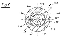
図9は他の実施形態による雄型素子102の断面図を示す。雄型素子102は、図1〜8に示す雄型素子2の送給窪み15及び帰還窪み16と同様の送給窪み115及び帰還窪み116を有する第1通路手段を設けた第1コンポーネント106を備える。雄型素子102は、さらに、図1〜8に示す雄型素子2の第2コンポーネント7と同様に機能する第2コンポーネント107を備える。第2コンポーネント107には、複数個のチャネル120を有する第2通路手段を設ける。
FIG. 9 shows a cross-sectional view of a
図9に示す雄型素子102と、図1〜8に示す雄型素子2との主な相違点は、チャネル120が送給窪み115及び帰還窪み116に正面から連通する点である。換言すれば、チャネル120は、長手方向軸線Zに対して横切る、とくに、直交する平面として構成される境界ゾーンに沿って送給窪み115及び帰還窪み116に対面する。これとは対照的に、図1〜8の実施形態では、チャネル20と窪み15,16との境界ゾーンは円筒形態を有していた。
The main difference between the
第2コンポーネント107は管状形態を有することができ、この場合、チャネル120を、第2コンポーネント107の内面に設ける。第1コンポーネント106及び第2コンポーネント107は、長手方向軸線Zに沿って順次に配置する。管状コンポーネント100を、送給窪み115、帰還窪み116及びチャネル120を半径方向に閉じるように、第1コンポーネント106及び第2コンポーネント107の内側に配置する。
The
雄型素子102に関しても同様に、第1コンポーネント106に設けた第1通路手段が第2コンポーネント107に設けた第2通路手段に流体連通する複数個の角度位置を画定することができる。第2コンポーネント107の第1コンポーネント106に対する角度位置に無関係に正確になるよう、常に少なくとも1個のチャネル120が第1の送給窪み115に対面し、また少なくとも1個の他のチャネル120が第2の帰還窪み116に対面する。
Similarly for the
送給窪み115に連通するチャネル120は複数個の流入路122を画定し、これら流入路122は、図7に示した環状導管27と全く同様の環状導管に至る。帰還窪み116に連通するチャネル120は複数個の流出路123を画定し、これら流出路123は、環状導管に連通し、冷却流体を排出する。
A
図9に破線で示した1個又は複数個のチャネル120は、第1コンポーネント106における送給窪みを帰還窪みから分離する対応部分に対面することができる。これらチャネルは送給窪み115を帰還窪み116から分離する。
One or
図10は、代替的実施形態による雄型素子202の断面図を示し、この雄型素子202は、第1コンポーネント206及び第2コンポーネント207を有する管状形成部材を備え、第2コンポーネント207を第1コンポーネント206内に部分的に挿入する。図10に示す雄型素子202は、図1〜8に示す雄型素子2とは、主に、送給窪み、帰還窪み及びチャネルの位置が、図1〜8に示す雄型素子2と比べて逆転している点である。
FIG. 10 shows a cross-sectional view of a
とくに、雄型素子202の第1コンポーネント206に複数個のチャネル220を設け、これらチャネル220が長手方向軸線Zの周りに長手方向に延在する。チャネル220は第1コンポーネント206の内面に得られる。
In particular, the
その代わり、第2コンポーネント207に送給窪み215及び帰還窪み216を設け、これら窪みは、第1コンポーネント206内に挿入するのに適合するよう第2コンポーネント207の外面に設ける。送給窪み215及び帰還窪み216は互いに直径方向に対向させることができる。送給窪み215及び帰還窪み216は、それぞれ雄型素子202の長手方向軸線の周りに測った角度寸法を有し、この角度寸法は、各チャネル220の角度範囲よりも大きい。このようにして、第2コンポーネント207の第1コンポーネント206に対する複数の角度位置を画定することができ、これら角度位置において、少なくとも1個のチャネル220が送給窪み215に連通し、また少なくとも1個の他のチャネル220が帰還窪み216に連通する。とくに、チャネル220は長手方向軸線の周りに均等に分布されているため、第2コンポーネント207に対する第1コンポーネント206の角度位置には無関係に、常に送給窪み215に対面する少なくとも1個のチャネル220が存在し、また帰還窪み216に対面する少なくとも1個の他のチャネル220が存在することになる。
Instead, the
送給窪み215に対面するチャネル220は流入路222を画定する。チャネル220は、第1コンポーネント206から突出する第2コンポーネント207の部分に沿って連続する。ここからチャネル220は、例えば、第2コンポーネント207の周りに配置した第3コンポーネントにより閉じられる。チャネル220は、図7における環状導管27と同様の環状導管に至り、流入路222は環状導管に連通する。
A
同様に、帰還窪み216に対面するチャネル220は流出路223を画定し、この流出路も同様に環状導管に連通する。
Similarly, the
図11は、他の実施形態による雄型素子302の端面図を示す。この雄型素子302は、第1コンポーネント306、及びこの第1コンポーネント306内に少なくとも部分的に挿入する第2コンポーネント307を備える。
FIG. 11 shows an end view of a
第2コンポーネント307には、送給窪み315及び帰還窪み316を設け、これら窪みは第2コンポーネント307の外面に、例えば、直径方向に互いに対向する位置に配置することができる。送給窪み315及び帰還窪み316は、雄型素子302の長手方向軸線に平行に延在させる。
The
第1コンポーネント306に1対のチャネル320を設け、これらチャネル320は、例えば、直径方向に互いに対向させ、また雄型素子302の長手方向軸線Zに平行な方向に延在させる。チャネル320は第1コンポーネント306の内面に設け、送給窪み315及び帰還窪み316を設けた第2コンポーネント307の外面に接触するよう配置する。
The
各チャネル320は、雄型素子302の長手方向軸線の周りに測った角度寸法Aを有し、この角度寸法Aは、送給窪み315及び帰還窪み316の角度寸法Bよりも小さい。例えば、角度寸法Bは角度寸法Aの3〜4倍とすることができる。
Each channel 320 has an angular dimension A measured around the longitudinal axis of the
このようにして、送給窪み315がチャネル320に連通し、また帰還窪み316が他のチャネル320に連通する、第1コンポーネント306の第2コンポーネント307に対する複数の角度位置が存在する。図11には、例として、これら位置のうち1つの位置を実線で示し、他の2つの位置P1及びP2を破線で示す。
In this way, there are a plurality of angular positions of the
第2コンポーネント307は第1コンポーネント306に着脱可能に取付けることができる。例えば、第2コンポーネント307を第1コンポーネント306にねじ付けることができる。第1コンポーネント306を第2コンポーネント307にロックするとき、送給窪み315が1つのチャネル320に対面し、また帰還窪み316が他のチャネル320に対面するのを確実にするためには、第1コンポーネント306及び第2コンポーネント307に設けたねじ山の開始ポイントに関して、比較的広い公差、例えば約30゜の公差を与えることで十分である。実際、第1通路手段すなわちチャネル320が、第2通路手段すなわち送給窪み315及び帰還窪み316に流体連通する複数の角度位置が存在するので、比較的広い公差が各ねじ山の開始ポイントに与えられている場合でも、冷却流体は、第1コンポーネント306から第2コンポーネント307へ、又はその逆向きに通過することができる。
The
図11は、第1通路手段が第2通路手段に流体連通しない場合、第2コンポーネント307を第1コンポーネント306に対して回転する例を提供する。それにもかかわらず、チャネル320及び窪み315,316は、複雑なタイミングシステムに依存することなく達成するのが容易な機械加工公差に起因して連通するような寸法にする。
FIG. 11 provides an example of rotating the
図12は、代替的実施形態による雄型素子402を示す。
FIG. 12 shows a
図1及び図2に示す雄型素子2は、容器用のキャップを形成する構成としたが、図12に示す雄型素子402は、射出成形又は圧縮成形によって、容器、とくにボトル用のプリフォーム(予備成形品)を成形するよう構成する。雄型素子402によって得られるプリフォームは、その後にブロー成形又は延伸ブロー成形によって、容器、とくにボトルに変形することができる。
The
雄型素子402は、外側からプリフォームを形成するのに適した図示しない雌型素子をも有する成形ユニットに設ける。成形ユニットは、さらに、アンダーカットゾーンを設けたプリフォームのネック部を外側から形成するための少なくとも2つの可動インサートを有する。
The
雄型素子402は、プリフォームを内側から形成するのに適した中心形成コア403を備える。図示の実施形態において、中心形成コア403は、プリフォームの底面、及びプリフォームの側壁における底面に近接する部分を内側から形成するのに適した第1形成要素451を有する。中心形成コア403は、さらに、プリフォームの側壁における底面から遠い側の部分を内側から形成するのに適した第2形成要素452を有する。第2形成要素452は第1形成要素451に固着する。
The
代替的実施形態において、中心形成コア403は一体ピースで形成することができる。
In an alternative embodiment, the
雄型素子402は、さらに、プリフォームの底面とは反対側の部分からプリフォームを区切るプリフォームの環状端縁を形成するのに適した環状形成部材404を備える。
The
環状形成部材404は、中心形成コア403を包囲する。中心形成コア403は環状形成部材404から図示しない雌型素子に向かって突出する。
The annular forming
環状形成部材404及び中心形成コア403は、雄型素子402の動作中、とくに、成形型を閉じてプリフォームを形成するとき、及びプリフォームを成形型から引出すとき、互いに相対移動することができる。
The annular forming
雄型素子402は、長手方向軸線Z1に沿って延在する第1コンポーネント406を備える。
The
雄型素子402は、さらに、第1コンポーネント406に連結する第2コンポーネント407を備える。第2コンポーネント407は、第1コンポーネント406に適当な着脱可能連結、例えばねじ連結によって連結することができる。図示の実施形態において、第2コンポーネント407は、第1コンポーネント406に直接ねじ付ける。
The
中心形成コア403は、第1コンポーネント406によって支持することができ、例えば、第1コンポーネント406にねじ付けることができる。
The centering
第2コンポーネント407は、部分的に第1コンポーネント406内に、また部分的に中心形成コア403内に突入する。
The
雄型素子402において、液状又はガス状の冷却流体を循環させてプリフォームを冷却できる冷却回路を設ける。
The
冷却回路は、第1コンポーネント406に設けた流入導管413を有する。流入導管413は、少なくとも一部が長手方向軸線Z1に平行な方向に延在する。
The cooling circuit has an
冷却回路は、さらに、同様に第1コンポーネント406に設けた流出導管418を有する。流出導管418は、例えば、流入導管413に対して直径方向に対向する位置で、少なくとも一部が長手方向軸線Z1に平行な方向に延在する。
The cooling circuit further has an
第1コンポーネント406には冷却流体のための第1通路手段を設ける。第1通路手段は、第1コンポーネント406の内面に設けた送給窪み415及び帰還窪み416を有する。とくに、第1通路手段は、第1コンポーネント406における一方の端部であって、第2コンポーネント407の端部領域を挿入する側の端部に設けることができる。
The
流入導管413は送給窪み415に至るとともに、流出導管418は帰還窪み416から延びる。
The
第2コンポーネント407には第2通路手段を設け、この第2通路手段は、第2コンポーネント407の外面に設けた複数個のチャネル420を有することができる。チャネル420は、長手方向軸線Z1に平行な方向に延在し、長手方向軸線Z1の周りに均等に分布させることができる。
The
チャネル420は、第2コンポーネント407の第1コンポーネント406内に挿入する端部領域に達し、したがって、送給窪み415及び帰還窪み416に対面することができる。チャネル420は、さらに、第1コンポーネント406から突出する第2コンポーネント407の部分に連続し、形成すべきプリフォームに向かう。この部分において、チャネル420は中心形成コア403によって半径方向を閉じられる。
The
第1通路手段及び第2通路手段は、長手方向軸線Z1の周りに分布させ、この分布は、長手方向軸線Z1の周りに第1コンポーネント406に対する第2コンポーネント407の複数個の角度位置を画定することができ、これら角度位置において、第1通路手段が第2通路手段に流体連通できるように行う。この目的のため、送給窪み415、帰還窪み416及びチャネル420は、図4及び5、図9〜11に示すような形態のうち任意なものとすることができる。
The first passage means and the second passage means are distributed about the longitudinal axis Z1, and this distribution defines a plurality of angular positions of the
とくに、第1通路手段及び第2通路手段は、第2コンポーネント407を第1コンポーネント406に対して角度的な位置決めをするが、少なくとも1個のチャネル420が常に送給窪み415に対面し、また少なくとも1個の他のチャネル420が帰還窪み416に対面するよう構成することができる。このようにして、冷却回路は、第2コンポーネント407を第1コンポーネント406にどのように取付けても有効に機能する。したがって、複雑なタイミングシステムを使用する必要はない。
In particular, the first passage means and the second passage means angularly position the
冷却回路は、さらに長手方向軸線Z1周りに延在する環状導管427を有する。環状導管427の中央ラインは、長手方向軸線Z1に交差する、とくに直交する平面内に存在する。環状導管427は、第2コンポーネント407と中心形成コア403との間に画定することができる。
The cooling circuit further has an
チャネル420は第2コンポーネント407の外面に沿って、環状導管427に達するまで延在する。
The
冷却流体は流入導管413を経て雄型素子402に流入し、ここから送給窪み415に流入する。送給窪み415に対面するチャネル420を経て、冷却流体は環状導管427に達する。この環状導管427から冷却流体は帰還窪み416に連通するチャネル420に流入し、この後流出導管418を経由して雄型素子402から流出する。
The cooling fluid flows into the
環状導管427は、プリフォームの開放端部を形成する中心形成コア403の表面近傍に配置する。環状導管427は、したがって、プリフォームのネック部を冷却することを意図する。
An
雄型素子402は、さらに、プリフォームの底面を冷却する他の冷却回路を有する。この他の冷却回路は、プリフォームの側壁、すなわちネック部と底面との間に介在する部分を冷却することを意図する。
The
他の冷却回路は吸入導管429を有し、この吸入導管429は管状素子430内で長手方向軸線Z1に沿って第1コンポーネント406と同軸状に延在する。吸入導管429は中心形成コア403内まで連続し、中心形成コア403のプリフォームの底面を形成する部分の近傍で終端する。
Another cooling circuit includes a
環状チャンバ453が中心形成コア403内に画定され、これにより吸入導管429から入来する冷却流体はプリフォームの側壁を冷却することができる。環状チャンバ453から冷却流体は、管状素子430の外側に画定した排出導管432に流入し、次に雄型素子402から流出する。
An
プリフォームのネック部を冷却する冷却回路及びプリフォームの底面及び側壁を冷却する他の冷却回路は互いに独立している。換言すれば、雄型素子402において、冷却回路内で循環する冷却流体は、他の冷却回路内で循環する冷却流体とは混合しない。
The cooling circuit that cools the neck of the preform and the other cooling circuits that cool the bottom and side walls of the preform are independent of each other. In other words, in the
図13は、ポリマー材料で形成される物体505、例えば容器のキャップを得る成形ユニット60を示す。
FIG. 13 shows a molding unit 60 that obtains an
図13につき以下に説明することは、キャップ以外の物体、例えば、シール、プリフォーム又は容器を形成するよう構成した成形型にも適用することができる。 What is described below with respect to FIG. 13 can also be applied to molds configured to form objects other than caps, such as seals, preforms or containers.
成形ユニット60は、物体505を内側から形成するのに適した雄型素子502を有する。成形ユニット60は、さらに、物体505の外面を形成するのに適した雌型素子61を有する。
The forming unit 60 has a
図13に示す実施形態において、雄型素子502及び雌型素子61は圧縮成形によって物体505を得るよう構成する。以下に説明することは、しかし、射出成形によって得られる物体にも適用することができる。雄型素子502は、物体505の底壁を内側から形成する形成端部を有する中心形成コア503を備える。中心形成コア503の形成端部は、さらに、物体505の底壁から突出する封止リップの部分を形成するよう構成する。
In the embodiment shown in FIG. 13,
中心形成コア503は長手方向軸線Z2に沿って延在する。
The
雄型素子502は、さらに、中心形成コア503の外側に配置し、図14に詳細に示すような管状形成部材504を有する。とくに、管状形成部材504は中心形成コア503を包囲する。
The
管状形成部材504は、物体505の封止リップの部分を形成するよう配置した造形端部62を有する。より具体的には、中心形成コア503は封止リップの内面を形成するとともに、管状形成部材504は封止リップの外面を形成する。
管状形成部材504の造形端部62は、さらに、物体505の側壁を内側から形成するよう配置する。物体505がキャップである場合、側壁には、緊締要素、例えばねじ山を設け、キャップを閉鎖すべき容器に締付けるようにする。
The
管状形成部材504の造形端部62は、とくに、物体505がキャップではない場合に、上述したのとは異なる構成にすることができると理解されたい。
It should be understood that the
管状形成部材504はヒートパイプとして構成する。とくに、管状形成部材504は(図14には見えていない場合であっても)、内側が中空で液体を収納し、この液体は管状形成部材504の内側に画定される容積の一部に充填する。管状形成部材504及びより一般的にはヒートパイプの動作原理は、ヒートパイプ内に収納される液体の状態変化に起因して物体505から熱を除去することに基づく。成形されているポリマー材料が発生する熱の結果として、液体は液相からガス相に移行する。
The
雄型素子502は、さらに、管状形成部材504又はより一般的に言えばヒートパイプを冷却するための冷却回路を備える。冷却回路は、管状形成部材504を支持するコンポーネント506の内側に部分的に設ける。管状形成部材504は、着脱可能連結により、例えば、ねじ連結によって、コンポーネント506に取付けることができる。
The
コンポーネント506は管状の形態を有することができる。
管状形成部材504はコンポーネント506内に収容される端部領域を有する。
冷却回路は、コンポーネント506に設けた、例えば、コンポーネント506の厚みに貫通する流入導管513を有する。
The cooling circuit has an inflow conduit 513 provided in the
流入導管513は長手方向導管とする、すなわち、長手方向軸線Z2に平行に延在させることができる。さらに、同様にコンポーネント506に設けた図示しない流出導管を設ける。流出導管も長手方向に、すなわち、長手方向軸線Z2に平行に延在させることができる。流出導管は、流入導管513に対して直径方向に対向する位置に設けることができる。
The inflow conduit 513 can be a longitudinal conduit, i.e., extend parallel to the longitudinal axis Z2. Further, an outflow conduit (not shown) provided in the
流入導管513及び図示しない流出導管は環状導管527に連通し、この環状導管527は管状形成部材504を冷却するよう配置する。環状導管527は、コンポーネント506と管状形成部材504との間に画定される。
The inflow conduit 513 and the unillustrated outflow conduit communicate with an
環状導管527は、長手方向軸線Z2に交差する、とくに、長手方向軸線Z2に直交する平面内で、リング状に閉じたラインとして構成される延長ラインに沿って延在することができる。2個の封止リング64を、コンポーネント506と管状形成部材504との間で環状導管527の両側側面に介在させることができる。封止リング64により、コンポーネント506と管状形成部材504との間で冷却流体が漏洩するのを防止する。雄型素子502は、さらに、中心形成コア503を冷却するのに適した他の冷却回路を有する。
The
この他の冷却回路は、長手方向軸線Z2に沿って延在する管状素子530の内側に設けた吸入導管529を有する。管状素子530は、中心形成コア503内に配置する。
This other cooling circuit has a
吸入導管529を介して、他の冷却回路を循環する冷却流体は中心形成コア503の形成端部近傍に移送され、物体505の底壁、及び必要であれば封止リップを冷却することができる。
Via the
排出導管532を中心形成コア503内に設け、冷却流体が物体505を冷却した後に他の冷却回路を循環する冷却流体を排出できるようにする。排出導管532は、管状素子530と中心形成コア503との間のギャップによって画定することができる。
A
中心形成コア503内に設けた他の冷却回路は、管状形成部材504を冷却する冷却回路とは独立している。
The other cooling circuit provided in the
雄型素子502の他のコンポーネントは図1につき説明した雄型素子2のコンポーネントと同一であり、再び詳細には説明しない。
The other components of the
動作中、物体505を雄型素子502と雌型素子61との間で造形している間に管状形成部材504が実現するヒートパイプは、物体505を形成している熱ポリマー材料を冷却する。ヒートパイプ内に収納される液体は、加熱されてガス相に移行し、これにより物体からの大量の熱を除去する。
In operation, the heat pipe realized by the
冷却流体は、管状形成部材504に関連する冷却回路に流入導管513から流入する。冷却流体は環状導管527に達し、管状形成部材504、すなわちヒートパイプを冷却する。とくに、冷却流体は、管状形成部材504の造形端部62とは反対側の端部領域63を冷却する。
The cooling fluid flows from the inlet conduit 513 into the cooling circuit associated with the
管状形成部材504を冷却した後、冷却流体は、コンポーネント506に設けた図示しない流出導管を経て冷却回路から流出する。
After cooling the
同時に、中心形成コア503に関連する他の冷却回路を循環する冷却流体は、中心形成コア503の温度を制限された状態に維持することができる。
At the same time, the cooling fluid circulating through other cooling circuits associated with the centering
したがって、物体505は効果的に冷却され、生産速度を増大し、またサイクルタイムを減少することができる。
Thus, the
図示の実施形態において、ヒートパイプは、物体505を形成するポリマー材料に接触することを意図する素子、すなわち環状形成部材504をなす。
In the illustrated embodiment, the heat pipe forms an element that is intended to contact the polymeric material forming the
代替的実施形態において、ヒートパイプを使用して、管状形成部材504以外のポリマー材料に接触することを意図する型コンポーネントを実現することができる。例えば、ポリマー材料に接触することを意図する雌型素子61の1個又は複数個のコンポーネントをヒートパイプで実現することができる。さらに、ヒートパイプを使用してポリマー材料に直接接触する必要はない型コンポーネントを実現することができ、この場合、ヒートパイプは、プラスチック材料と相互作用する形成素子から熱を排除するよう配置する。
In an alternative embodiment, a heat pipe can be used to achieve a mold component that is intended to contact a polymeric material other than the tubular forming
例えば、管状形成部材504は2個のパーツで実現することができ、すなわち造形端部62を管状形成部材504の残りの部分とは明確に異なるコンポーネントとして形成することができる。
For example, the
この場合、造形端部62は、熱伝導特性がよい材料で形成した中実体として構成することができる。その代わり、管状形成部材504の残りの部分はヒートパイプで実現することができる。
In this case, the
この後者の解決法は、造形端部が幾分複雑なジオメトリを有しており、ヒートパイプで実現するのが困難なときに、うまく利用できる。結論として、ヒートパイプは、物体と冷却流体が循環する冷却回路との間に介在させることができる型コンポーネントを実現するのに使用でき、必ずしも物体を形成するポリマー材料と直接接触させるよう設計しない場合であっても使用できる。 This latter solution can be successfully used when the shaped end has a somewhat complex geometry and is difficult to implement with a heat pipe. In conclusion, heat pipes can be used to realize mold components that can be interposed between the object and the cooling circuit through which the cooling fluid circulates, and are not necessarily designed to be in direct contact with the polymer material that forms the object Can even be used.
図15は、ポリマー材料製の物体を射出成形又は圧縮成形によって形成するのに適した雄型素子の管状形成部材604を示す。図15に部分的に示す雄型素子によって形成する物体は、例えば、容器用のキャップ、キャップ用のシール、又は容器、とくにボトルを得るためのプリフォームとすることができる。管状形成部材604は長手方向軸線Z3を有する。
FIG. 15 shows a male element
管状形成部材604は形成端部662を有し、この形成端部662の形状は図15には略図的に描いており、またポリマー材料と相互作用して所望のジオメトリに従うようポリマー材料を形成する。
管状形成部材604は、さらに、形成端部662とは反対側の支持端部663を有し、雄型素子の図示しない支持素子に緊締できるようにする。
The
管状形成部材604は2個のパーツで実現することができる。とくに、管状形成部材604は、外側コンポーネント607及び図15に破線で示した内側コンポーネント608を有することができる。
外側コンポーネント607及び内側コンポーネント608は、双方ともにほぼ管状形態とすることができる。内側コンポーネント608は外側コンポーネント607の内側に外側コンポーネント607と同軸状にして配置する。内側コンポーネント608及び外側コンポーネント607を着脱可能な、すなわち非恒久的な連結により互いに連結する。
Both the
管状形成部材604には、管状形成部材604内を冷却流体が循環できる冷却回路を設け、形成端部662を冷却できるようにする。
The
冷却回路は、管状形成部材604の形成端部に設けた環状導管627を有する。この環状導管627は、外側コンポーネント607と内側コンポーネント608との間に画定することができる。例えば、環状導管627は、外側コンポーネント607に設けた溝であって、滑らかな外面を有し得る内側コンポーネント608によって半径方向を閉じられる溝によって画定することができる。さらに、環状導管627は、内側コンポーネント608に設けた溝、又は内側コンポーネント608及び外側コンポーネント607にそれぞれ設けた互いに対向する2個の溝によって画定することができる。
The cooling circuit has an
環状導管627は、長手方向軸線Z3の周りにリング状に包囲する延在ラインに沿って延在する。延在ラインは、長手方向軸線に交差する、とくに、長手方向軸線に直交する平面内に存在することができる。この延在ラインは円形とすることができる。
The
流入路622は環状導管627に連通し、例えば、環状導管627に至る。流入路622は、外側コンポーネント607と内側コンポーネント608との間に画定する。
The
流入路622により雄型素子に流入する冷却流体が環状導管627に到達できる。流入路622は管状形成部材604内に長手方向に延在する。とくに、流入路622は長手方向軸線Z3に平行とすることができる。
The cooling fluid flowing into the male element through the
冷却回路は、さらに、環状導管627に連通する流出路623を有し、環状導管627を循環する冷却流体を支持端部663に移送できるようにする。とくに、流出路623は、外側コンポーネント607と内側コンポーネント608との間に画定する。
The cooling circuit further includes an
流出路623によれば、冷却流体は環状導管627を通過した後雄型素子から流出できる。
According to the
流出路623は、やはり管状形成部材604内に長手方向に延在する。とくに、流出路623は長手方向軸線Z3に平行とすることができる。
図15に示す実施形態において、流入路622及び流出路623は、外側コンポーネント607の内面に形成したそれぞれに対応する長手方向のチャネル620によって画定する。チャネル620は、内側コンポーネント608の外面によって半径方向を閉じられる。
In the embodiment shown in FIG. 15, the
代案として、流入路622及び/又は流出路623は、内側コンポーネント608の外面に設けたそれぞれに対応する長手方向のチャネル620によって画定し、外側コンポーネント607の内面によって半径方向を閉じられるようにする。
Alternatively, the
さらに、内側コンポーネント608及び外側コンポーネント607の双方に、それぞれに対応する長手方向のチャネルを設け、互いに対向させるとき流入路622及び/又は流出路623を画定するようにする。
In addition, both the
いずれにせよ、流入路622及び流出路623は、それぞれ長手方向軸線Z3周りに少なくとも10゜の角度寸法、好適には、少なくとも30゜の角度寸法を有することができる。このようにして、流入路622及び流出路623は、形成端部662を効果的に冷却するような冷却流体の大きな流れを確保する。
In any case, the
流入路622及び流出路623は、直径方向に互いに対向させて配置することができる。
The
代替的実施形態において、冷却回路は、長手方向軸線Z3周りに分布させた複数個の流入路622を有し、冷却流体を環状導管627に移送できるようにする。
In an alternative embodiment, the cooling circuit has a plurality of
冷却回路は、さらに、長手方向軸線Z3周りに分布させた複数個の流出路623を有し、冷却流体を環状導管627から排出できるようにする。
The cooling circuit further includes a plurality of
この場合、長手方向軸線Z3の周りにおける流入路622の角度寸法の合計は、少なくとも10゜の角度、好適には、30゜の角度より大きい角度となるようにする。同じことは、流出路623の角度寸法についてもあてはまる。
In this case, the sum of the angular dimensions of the
管状形成部材604は、さらに、支持端部663に配置した接続コンポーネント606を有し、管状形成部材604に設けた冷却回路に冷却流体を供給し、またこの冷却回路から冷却流体を排出できるようにする。
この目的のため、接続コンポーネント606には、流入孔のような形状の流入口615を設け、図示しない冷却流体源から入来する冷却流体を流入路622に送給できるようにする。
For this purpose, the
接続コンポーネント606には、さらに、流出孔のような形状の流出口616を設け、流出路623からの冷却流体を排出できるようにする。
The
流入口615及び流出口616は、長手方向に、すなわち長手方向軸線Z3に平行に配置し、例えば、長手方向軸線Z3に関して直径方向に互いに対向させて配置することができる。
The
流入口615及び流出口616は、それぞれ境界ゾーン670に沿って流入路622及び流出路623に対面させ、境界ゾーン670は、長手方向軸線Z3に交差する、とくに、長手方向軸線Z3に直交する平坦境界面として構成することができる。
The
境界ゾーン670において、外側コンポーネント607は接続コンポーネント606に接触する。
In the
長手方向軸線Z3の周りに境界ゾーン670で測った流入路622及び流出路623の角度寸法は、それぞれに対応する流入口615及び流出口616の角度範囲よりも大きい。このようにして、流入口615が流入路622に流体連通しまた流出口616が流出路623に流体連通する外側コンポーネント607の接続コンポーネント606の複数個の角度位置を画定することができる。
The angular dimensions of the
流入口615及び流出口616は第1通路手段を画定するとともに、流入路622及び流出路623が第2通路手段を画定し、接続コンポーネント606に対する外側コンポーネント607の複数個の角度位置で、第1通路手段は(とくに、対面する)第2通路手段と流体連通する。
The
接続コンポーネント606には、支持素子の孔に係合できる、例えばピンのような形状にした基準素子665を設け、接続コンポーネント606を確実に所定角度位置で支持素子に取付けるようにする。
The
雄型素子は、さらに、管状形成部材604内に配置する中心形成コアを備え、とくに、物体の底壁を得るのが望ましい、物体の一部分を形成できるようにする。キャップ又はシールを形成するよう雄型素子を構成する場合、中心形成コアは、図1及び2に示す中心形成コア3に類似の構造を有することができる。
The male element further comprises a central forming core disposed within the
中心形成コア内に他の冷却回路を設け、この冷却回路内で冷却流体が循環して中心形成コアによって形成される物体の一部分を冷却する。 Another cooling circuit is provided in the centering core, in which cooling fluid circulates to cool a portion of the object formed by the centering core.
中心形成コアの設けた他の冷却回路は、管状形成部材604に設けた冷却回路とは独立している。換言すれば、2つの回路で循環する冷却流体は、雄型素子内で互いに混ざり合わない。
The other cooling circuit provided with the center forming core is independent of the cooling circuit provided in the
上述の冷却回路及び他の冷却回路は、中心形成コア及び管状形成部材604の有効な冷却を可能にし、とくに、例えば、形成した物体のアンダーカットを設けた部分を雄型素子から外すため、中心形成コア及び管状形成部材604が相対移動できる場合に、有効冷却を可能にする。
The cooling circuits described above and other cooling circuits allow for effective cooling of the center forming core and
一般的に言えば、送給窪み及び帰還窪み、チャネル、流入路及び流出路の形状及び寸法、並びにそれらの個数は、冷却流体の十分な流れが確保できるのであれば、自由に選択することができる。例えば、部分円形断面を有するチャネル、窪み又は通路は、工作機械を用いる機械加工によって極めて簡単に得ることができるが、部分円形断面以外の形状にすることもできる。さらに、冷却流体の流れが等しい場合、窪み、チャネル又は通路の角度範囲を減少し、またこれら窪み、チャネル又は通路の深さを増加することができる。このことは、図示した実施形態のすべてにあてはまる。 Generally speaking, the shape and dimensions of the feed and return wells, channels, inflow and outflow channels, and their number can be freely selected as long as a sufficient flow of cooling fluid can be secured. it can. For example, channels, depressions or passages having a partial circular cross section can be obtained very simply by machining with a machine tool, but can also have shapes other than a partial circular cross section. Further, if the cooling fluid flows are equal, the angular range of the depressions, channels or passages can be reduced and the depth of these depressions, channels or passages can be increased. This is true for all of the illustrated embodiments.
Claims (23)
前記第1通路手段(15,16;115,116;215,216;315,316;415,416;615,616)及び前記第2通路手段(20;120;220;320;420;620)を、前記雄型素子の長手方向軸線(Z;Z1;Z3)の周りに分布させ、前記第1通路手段(15,16;115,116;215,216;315,316;415,416;615,616)が前記第2通路手段(20;120;220;320;420;620)に流体連通する、前記第2コンポーネント(7;107;207;307;407;607)に対する前記第1コンポーネント(6;106;206;306;406;606)の複数の角度位置が存在するよう構成する、該雄型素子において、
前記第2コンポーネント(7;107;207;307;407;607)を前記第1コンポーネント(6;106;206;306;406;606)に着脱可能連結によって固着し、この固着は、前記雄型素子の動作中に前記第2コンポーネント(7;107;207;307;407;607)が前記第1コンポーネント(6;106;206;306;406;606)に対して回転不能に取付けられるように行うことを特徴とする、雄型素子。 First element means (15, 16; 115, 116; 215, 216; 315, 316; 415, 416; 615, 616) provided in the first component (6; 106; 206; 306; 406; 606) of the male element. And a second passage means (20; 120; 220; 320; 420; 620) provided in the second component (7; 107; 207; 307; 407; 607) of the male element With
The first passage means (15, 16; 115, 116; 215, 216; 315, 316; 415, 416; 615, 616) and the second passage means (20; 120; 220; 320; 420; 620) are connected to the longitudinal axis of the male element ( Z; Z1; Z3) distributed around said first passage means (15, 16; 115, 116; 215, 216; 315, 316; 415, 416; 615, 616) said second passage means (20; 120; 220; 320; 420; 620) There are multiple angular positions of the first component (6; 106; 206; 306; 406; 606) relative to the second component (7; 107; 207; 307; 407; 607). Constituting the male element,
The second component (7; 107; 207; 307; 407; 607) is secured to the first component (6; 106; 206; 306; 406; 606) by means of a detachable connection, and this fastening is connected to the male mold. So that the second component (7; 107; 207; 307; 407; 607) is non-rotatably attached to the first component (6; 106; 206; 306; 406; 606) during operation of the element A male element characterized in that it performs.
前記第2通路手段(20;120;220;320;420;620)は、前記緊締端部から前記他の端部に向かって延在し、また第1コンポーネントと前記第2コンポーネントとの間における境界ゾーン(70;670)における前記第1通路手段(15,16;115,116;215,216;315,316;415,416;615,616)に対面する、雄型素子。 3. The male element according to claim 1 or 2, wherein the second component (7; 107; 207; 307; 407; 607) is attached to and detached from the first component (6; 106; 206; 306; 406; 606). A tightening end that can be fixed, and another end opposite to the tightening end;
The second passage means (20; 120; 220; 320; 420; 620) extends from the clamped end toward the other end and between the first component and the second component. Male element facing said first passage means (15, 16; 115, 116; 215, 216; 315, 316; 415, 416; 615, 616) in the boundary zone (70; 670).
前記第1通路は、前記第2通路における長手方向軸線周りの角度寸法(A)よりも大きい、長手方向軸線周りの角度寸法(B)を有し、これにより前記少なくとも1個の第2通路は、前記複数の角度位置において、前記第2通路の角度寸法全体にわたり、前記少なくとも1個の第1通路に対面するようになる、雄型素子。 7. The male element according to any one of claims 1 to 6, wherein the first passage means comprises at least one longitudinal first passage (15,16; 115,116; 215,216; 315,316; 415,416; 615,616). And the second passage means comprises at least one longitudinal second passage (20; 120; 220; 320; 420; 620);
The first passage has an angular dimension (B) about a longitudinal axis that is larger than an angular dimension (A) about a longitudinal axis in the second passage, whereby the at least one second passage is A male element that, at the plurality of angular positions, faces the at least one first passage over the entire angular dimension of the second passage.
前記第2通路手段は、前記長手方向軸線(Z;Z1;Z3)の周りに分布させた複数個のチャネル(20;120;220;320;420;620)を有する、雄型素子。 The male element according to any one of claims 1 to 7, wherein the first passage means comprises a feed well (15; 115; 215; 315; 415; 615) and a return well (16; 116; 216). 316; 416; 616)
The second passage means comprises a male element having a plurality of channels (20; 120; 220; 320; 420; 620) distributed about the longitudinal axis (Z; Z1; Z3).
前記複数個のチャネルのうち、少なくとも1個のチャネルは前記帰還窪み(16;116;216;316;416;616)に対面し、
また前記複数個のチャネルのうち、少なくとも1個のチャネル(20;120;220;320;420;620)は各分離面(17)に対面する、雄型素子。 12. The male element according to claim 11, wherein at least one of the plurality of channels faces the feeding depression (15; 115; 215; 315; 415; 615);
Of the plurality of channels, at least one channel faces the return recess (16; 116; 216; 316; 416; 616);
Further, among the plurality of channels, at least one channel (20; 120; 220; 320; 420; 620) is a male element facing each separation surface (17).
前記複数個のチャネルのいくつかのチャネル(20;120;220;320;420;620)は、前記第2コンポーネント(7;107;207;307;407;607)の外面に設けられる、雄型素子。 13. The male element according to any one of claims 8 to 12, wherein the feed well (15; 115; 215; 315; 415; 615) and the return well (16; 116; 216; 316; 416; 616) is provided on the inner surface of the first component (6; 106; 206; 306; 406; 606),
Several channels (20; 120; 220; 320; 420; 620) of the plurality of channels are provided on the outer surface of the second component (7; 107; 207; 307; 407; 607). element.
前記第1コンポーネント(6;106;206;306;406;606)及び前記第2コンポーネント(7;107;207;307;407;607)は、前記管状形成部材(4;404;604)に含まれる、雄型素子。 The male element according to any one of claims 1 to 13, further comprising a tubular forming member (4; 404; 604) provided with a forming surface forming part of the object (5),
The first component (6; 106; 206; 306; 406; 606) and the second component (7; 107; 207; 307; 407; 607) are included in the tubular forming member (4; 404; 604). It is, the male element.
前記第3コンポーネント(8;608)の側面が前記領域における前記チャネル(20;120;220;320;420;620)に対面して、前記チャネル(20;120;220;320;420;620)を閉じ、また対応の導管(24;25)を画定する、雄型素子。 16. The male element according to claim 15, wherein claim 14 is dependent on any one of claims 8-13, wherein several channels (20; 120; 220; 320) of said plurality of channels. 420; 620) is continuous along the region of the second component (7; 107; 207; 307; 407; 607) protruding from the first component (6; 106; 206; 306; 406; 606). ,
The side of the third component (8; 608) faces the channel (20; 120; 220; 320; 420; 620) in the region, and the channel (20; 120; 220; 320; 420; 620) A male element that closes and defines a corresponding conduit (24; 25).
Applications Claiming Priority (3)
| Application Number | Priority Date | Filing Date | Title |
|---|---|---|---|
| IT000072A ITMO20120072A1 (en) | 2012-03-21 | 2012-03-21 | MALE PIECE ELEMENT. |
| ITMO2012A000072 | 2012-03-21 | ||
| PCT/IB2013/052210 WO2013140351A1 (en) | 2012-03-21 | 2013-03-20 | A male mould element |
Publications (2)
| Publication Number | Publication Date |
|---|---|
| JP2015516894A JP2015516894A (en) | 2015-06-18 |
| JP5946582B2 true JP5946582B2 (en) | 2016-07-06 |
Family
ID=46124641
Family Applications (1)
| Application Number | Title | Priority Date | Filing Date |
|---|---|---|---|
| JP2015501037A Active JP5946582B2 (en) | 2012-03-21 | 2013-03-20 | Male element |
Country Status (13)
| Country | Link |
|---|---|
| US (2) | US10300633B2 (en) |
| EP (1) | EP2828054B1 (en) |
| JP (1) | JP5946582B2 (en) |
| KR (1) | KR101728083B1 (en) |
| CN (1) | CN104093534B (en) |
| BR (1) | BR112014017905B1 (en) |
| CA (1) | CA2861143C (en) |
| IN (1) | IN2014CN04941A (en) |
| IT (1) | ITMO20120072A1 (en) |
| MX (1) | MX371360B (en) |
| RU (1) | RU2587706C2 (en) |
| WO (1) | WO2013140351A1 (en) |
| ZA (1) | ZA201405044B (en) |
Families Citing this family (7)
| Publication number | Priority date | Publication date | Assignee | Title |
|---|---|---|---|---|
| US8585392B2 (en) * | 2011-05-24 | 2013-11-19 | F&S Tool, Inc. | Compression molding with successive stage cooling channels |
| FR3042148B1 (en) * | 2015-10-07 | 2018-04-13 | Centre Technique Des Industries Mecaniques | THERMOFORMING ASSEMBLY |
| IT201600076240A1 (en) * | 2016-07-20 | 2018-01-20 | Sacmi | PUNCH FOR COMPRESSION MOLDS |
| DE102017115821A1 (en) * | 2017-07-13 | 2019-01-17 | Mht Mold & Hotrunner Technology Ag | Multipart core insert |
| RU184442U9 (en) * | 2018-02-05 | 2018-11-22 | Публичное акционерное общество "АВТОВАЗ" | Mold Cooling Unit |
| US10858071B1 (en) | 2019-10-09 | 2020-12-08 | Dowco, Inc. | Universal cover |
| JP6938803B1 (en) * | 2021-01-28 | 2021-09-22 | 住友重機械工業株式会社 | Injection molding machine |
Family Cites Families (20)
| Publication number | Priority date | Publication date | Assignee | Title |
|---|---|---|---|---|
| US3740180A (en) * | 1971-10-19 | 1973-06-19 | Package Machinery Co | Core pin for plastic injection blow molding |
| JPS503169A (en) | 1973-05-14 | 1975-01-14 | ||
| DE2537037C3 (en) * | 1975-08-20 | 1978-07-13 | Fa. Hermann Heye, 3063 Obernkirchen | Fluid-cooled mold for molten glass |
| JPS59164109A (en) * | 1983-03-09 | 1984-09-17 | Matsushita Electric Ind Co Ltd | Cooling circuit device of metallic die |
| JPH0375893A (en) | 1989-08-17 | 1991-03-29 | Nec Corp | Ic card reader/writer |
| IT1274905B (en) | 1994-09-19 | 1997-07-25 | Sacmi | EQUIPMENT FOR THE MANUFACTURE OF PLASTIC MATERIALS IN PARTICULAR SCREW CAPS, BY PRESSURE MOLDING. |
| CA2160644C (en) | 1995-10-16 | 2005-05-24 | Jobst Ulrich Gellert | Cooled thread split inserts for injection molding preforms |
| JPH09262870A (en) | 1996-01-23 | 1997-10-07 | Sekisui Chem Co Ltd | Injection mold and its production |
| CN1042949C (en) | 1996-06-05 | 1999-04-14 | 中国石化兰州炼油化工总厂 | Lubricating oil compsn. |
| USRE38265E1 (en) * | 1997-01-24 | 2003-10-07 | Mold-Masters Limited | Injection molding apparatus having a cooled core |
| US5935621A (en) * | 1997-01-24 | 1999-08-10 | Mold-Masters Limited | Injection molding apparatus having a cooled core |
| US6352426B1 (en) * | 1998-03-19 | 2002-03-05 | Advanced Plastics Technologies, Ltd. | Mold for injection molding multilayer preforms |
| CA2255798C (en) | 1998-12-07 | 2008-06-17 | Jobst Ulrich Gellert | Injection molding cooling core having spiral grooves |
| DE10022289A1 (en) * | 2000-05-09 | 2001-11-29 | Innova Engineering Gmbh | Concentric casings in mutual contact, forming molding component with tempering channels, are permanently sealed along their contacting surfaces |
| CA2569639A1 (en) * | 2004-06-10 | 2005-12-29 | Advanced Plastics Technologies Luxembourg S.A. | Methods and systems for cooling molds |
| DE202005008170U1 (en) * | 2005-05-20 | 2005-07-28 | gwk Gesellschaft Wärme Kältetechnik mbH | Hollow cartridge shaped plastic preform molding tool has hollow inner tool part with longitudinal ribs supporting cooling tube |
| US7431582B2 (en) * | 2005-06-17 | 2008-10-07 | Rexam Closure Systems Inc. | Molding machine |
| ITMO20050224A1 (en) | 2005-09-07 | 2007-03-08 | Sacmi | MOLDS FOR MOLDING OF PLASTIC ITEMS AND METHOD TO PRODUCE A MOLD ELEMENT |
| CN201098979Y (en) | 2007-09-07 | 2008-08-13 | 四川天鑫塑胶管业有限公司 | Plastic inspection well main-well body die-casting forming die |
| CN101708644A (en) | 2009-12-25 | 2010-05-19 | 顾志元 | Energy-saving type plastic foaming mould |
-
2012
- 2012-03-21 IT IT000072A patent/ITMO20120072A1/en unknown
-
2013
- 2013-03-20 KR KR1020147020473A patent/KR101728083B1/en active IP Right Grant
- 2013-03-20 WO PCT/IB2013/052210 patent/WO2013140351A1/en active Application Filing
- 2013-03-20 BR BR112014017905-0A patent/BR112014017905B1/en active IP Right Grant
- 2013-03-20 US US14/371,684 patent/US10300633B2/en active Active
- 2013-03-20 JP JP2015501037A patent/JP5946582B2/en active Active
- 2013-03-20 MX MX2014008783A patent/MX371360B/en active IP Right Grant
- 2013-03-20 RU RU2014127152/05A patent/RU2587706C2/en active
- 2013-03-20 CN CN201380006214.3A patent/CN104093534B/en active Active
- 2013-03-20 EP EP13721086.0A patent/EP2828054B1/en active Active
- 2013-03-20 CA CA2861143A patent/CA2861143C/en active Active
-
2014
- 2014-06-30 IN IN4941CHN2014 patent/IN2014CN04941A/en unknown
- 2014-07-10 ZA ZA2014/05044A patent/ZA201405044B/en unknown
-
2019
- 2019-04-17 US US16/387,026 patent/US11123898B2/en active Active
Also Published As
| Publication number | Publication date |
|---|---|
| US20150044323A1 (en) | 2015-02-12 |
| IN2014CN04941A (en) | 2015-09-18 |
| US10300633B2 (en) | 2019-05-28 |
| US20190240872A1 (en) | 2019-08-08 |
| MX2014008783A (en) | 2014-10-13 |
| CA2861143A1 (en) | 2013-09-26 |
| JP2015516894A (en) | 2015-06-18 |
| EP2828054A1 (en) | 2015-01-28 |
| BR112014017905B1 (en) | 2020-12-15 |
| WO2013140351A1 (en) | 2013-09-26 |
| CN104093534A (en) | 2014-10-08 |
| CN104093534B (en) | 2016-06-22 |
| US11123898B2 (en) | 2021-09-21 |
| KR101728083B1 (en) | 2017-04-18 |
| EP2828054B1 (en) | 2018-07-25 |
| CA2861143C (en) | 2017-03-07 |
| BR112014017905A8 (en) | 2017-07-11 |
| RU2014127152A (en) | 2016-05-20 |
| MX371360B (en) | 2020-01-27 |
| KR20140138604A (en) | 2014-12-04 |
| ITMO20120072A1 (en) | 2013-09-22 |
| RU2587706C2 (en) | 2016-06-20 |
| ZA201405044B (en) | 2015-12-23 |
| BR112014017905A2 (en) | 2017-06-20 |
Similar Documents
| Publication | Publication Date | Title |
|---|---|---|
| JP5946582B2 (en) | Male element | |
| US7377767B2 (en) | Mold split insert | |
| CN101296790B (en) | Moulds for moulding objects made of plastics and a method for producing a mould element | |
| JP2005534534A (en) | Valve pin guide and centering system for injection molding equipment | |
| CN107639812B (en) | Container moulding unit with attached sheath impact device | |
| CA2744285A1 (en) | System for the post-treatment and transfer of preforms | |
| JP2019217768A (en) | Molding unit comprising movable boxing insert to be ventilated by fluid circuit tapped from boxing fluid circuit | |
| JP6802858B2 (en) | Punch for compression dies | |
| US20170151702A1 (en) | A mould tool for injection moulding | |
| KR101083436B1 (en) | A cooler of plunger for die casting | |
| TWI554380B (en) | A male mould element | |
| JP2011224906A (en) | Cooling liquid passage structure of mold and mold | |
| KR101599126B1 (en) | Mold forming machine of lid | |
| CN104723165A (en) | Liquid spraying device for machining machine | |
| JP2022011427A (en) | Molding mold member | |
| JP2012517917A (en) | Apparatus for forming an object |
Legal Events
| Date | Code | Title | Description |
|---|---|---|---|
| A621 | Written request for application examination |
Free format text: JAPANESE INTERMEDIATE CODE: A621 Effective date: 20150324 |
|
| A977 | Report on retrieval |
Free format text: JAPANESE INTERMEDIATE CODE: A971007 Effective date: 20151026 |
|
| A131 | Notification of reasons for refusal |
Free format text: JAPANESE INTERMEDIATE CODE: A131 Effective date: 20151110 |
|
| A521 | Request for written amendment filed |
Free format text: JAPANESE INTERMEDIATE CODE: A523 Effective date: 20160209 |
|
| TRDD | Decision of grant or rejection written | ||
| A01 | Written decision to grant a patent or to grant a registration (utility model) |
Free format text: JAPANESE INTERMEDIATE CODE: A01 Effective date: 20160524 |
|
| A61 | First payment of annual fees (during grant procedure) |
Free format text: JAPANESE INTERMEDIATE CODE: A61 Effective date: 20160531 |
|
| R150 | Certificate of patent or registration of utility model |
Ref document number: 5946582 Country of ref document: JP Free format text: JAPANESE INTERMEDIATE CODE: R150 |
|
| R250 | Receipt of annual fees |
Free format text: JAPANESE INTERMEDIATE CODE: R250 |
|
| R250 | Receipt of annual fees |
Free format text: JAPANESE INTERMEDIATE CODE: R250 |
|
| R250 | Receipt of annual fees |
Free format text: JAPANESE INTERMEDIATE CODE: R250 |
|
| R250 | Receipt of annual fees |
Free format text: JAPANESE INTERMEDIATE CODE: R250 |
|
| R250 | Receipt of annual fees |
Free format text: JAPANESE INTERMEDIATE CODE: R250 |