JP5939491B2 - LED projection module - Google Patents
LED projection module Download PDFInfo
- Publication number
- JP5939491B2 JP5939491B2 JP2014537424A JP2014537424A JP5939491B2 JP 5939491 B2 JP5939491 B2 JP 5939491B2 JP 2014537424 A JP2014537424 A JP 2014537424A JP 2014537424 A JP2014537424 A JP 2014537424A JP 5939491 B2 JP5939491 B2 JP 5939491B2
- Authority
- JP
- Japan
- Prior art keywords
- light
- light guide
- module according
- module
- recess
- Prior art date
- Legal status (The legal status is an assumption and is not a legal conclusion. Google has not performed a legal analysis and makes no representation as to the accuracy of the status listed.)
- Active
Links
- 238000009826 distribution Methods 0.000 claims description 73
- 230000003287 optical effect Effects 0.000 claims description 28
- 239000004020 conductor Substances 0.000 claims description 19
- 230000008878 coupling Effects 0.000 claims description 18
- 238000010168 coupling process Methods 0.000 claims description 18
- 238000005859 coupling reaction Methods 0.000 claims description 18
- 230000000694 effects Effects 0.000 description 3
- 230000003044 adaptive effect Effects 0.000 description 2
- 230000002238 attenuated effect Effects 0.000 description 2
- 238000001816 cooling Methods 0.000 description 2
- 238000007373 indentation Methods 0.000 description 2
- 230000007704 transition Effects 0.000 description 2
- 230000002745 absorbent Effects 0.000 description 1
- 239000002250 absorbent Substances 0.000 description 1
- 230000004075 alteration Effects 0.000 description 1
- 230000000254 damaging effect Effects 0.000 description 1
- 238000005562 fading Methods 0.000 description 1
- 230000005484 gravity Effects 0.000 description 1
- 238000009434 installation Methods 0.000 description 1
- 230000003068 static effect Effects 0.000 description 1
Images


Classifications
-
- F—MECHANICAL ENGINEERING; LIGHTING; HEATING; WEAPONS; BLASTING
- F21—LIGHTING
- F21S—NON-PORTABLE LIGHTING DEVICES; SYSTEMS THEREOF; VEHICLE LIGHTING DEVICES SPECIALLY ADAPTED FOR VEHICLE EXTERIORS
- F21S41/00—Illuminating devices specially adapted for vehicle exteriors, e.g. headlamps
- F21S41/10—Illuminating devices specially adapted for vehicle exteriors, e.g. headlamps characterised by the light source
- F21S41/14—Illuminating devices specially adapted for vehicle exteriors, e.g. headlamps characterised by the light source characterised by the type of light source
- F21S41/141—Light emitting diodes [LED]
- F21S41/143—Light emitting diodes [LED] the main emission direction of the LED being parallel to the optical axis of the illuminating device
-
- B—PERFORMING OPERATIONS; TRANSPORTING
- B60—VEHICLES IN GENERAL
- B60Q—ARRANGEMENT OF SIGNALLING OR LIGHTING DEVICES, THE MOUNTING OR SUPPORTING THEREOF OR CIRCUITS THEREFOR, FOR VEHICLES IN GENERAL
- B60Q1/00—Arrangement of optical signalling or lighting devices, the mounting or supporting thereof or circuits therefor
- B60Q1/02—Arrangement of optical signalling or lighting devices, the mounting or supporting thereof or circuits therefor the devices being primarily intended to illuminate the way ahead or to illuminate other areas of way or environments
- B60Q1/04—Arrangement of optical signalling or lighting devices, the mounting or supporting thereof or circuits therefor the devices being primarily intended to illuminate the way ahead or to illuminate other areas of way or environments the devices being headlights
- B60Q1/06—Arrangement of optical signalling or lighting devices, the mounting or supporting thereof or circuits therefor the devices being primarily intended to illuminate the way ahead or to illuminate other areas of way or environments the devices being headlights adjustable, e.g. remotely-controlled from inside vehicle
- B60Q1/08—Arrangement of optical signalling or lighting devices, the mounting or supporting thereof or circuits therefor the devices being primarily intended to illuminate the way ahead or to illuminate other areas of way or environments the devices being headlights adjustable, e.g. remotely-controlled from inside vehicle automatically
- B60Q1/085—Arrangement of optical signalling or lighting devices, the mounting or supporting thereof or circuits therefor the devices being primarily intended to illuminate the way ahead or to illuminate other areas of way or environments the devices being headlights adjustable, e.g. remotely-controlled from inside vehicle automatically due to special conditions, e.g. adverse weather, type of road, badly illuminated road signs or potential dangers
-
- B—PERFORMING OPERATIONS; TRANSPORTING
- B60—VEHICLES IN GENERAL
- B60Q—ARRANGEMENT OF SIGNALLING OR LIGHTING DEVICES, THE MOUNTING OR SUPPORTING THEREOF OR CIRCUITS THEREFOR, FOR VEHICLES IN GENERAL
- B60Q1/00—Arrangement of optical signalling or lighting devices, the mounting or supporting thereof or circuits therefor
- B60Q1/02—Arrangement of optical signalling or lighting devices, the mounting or supporting thereof or circuits therefor the devices being primarily intended to illuminate the way ahead or to illuminate other areas of way or environments
- B60Q1/04—Arrangement of optical signalling or lighting devices, the mounting or supporting thereof or circuits therefor the devices being primarily intended to illuminate the way ahead or to illuminate other areas of way or environments the devices being headlights
- B60Q1/14—Arrangement of optical signalling or lighting devices, the mounting or supporting thereof or circuits therefor the devices being primarily intended to illuminate the way ahead or to illuminate other areas of way or environments the devices being headlights having dimming means
- B60Q1/1415—Dimming circuits
- B60Q1/1423—Automatic dimming circuits, i.e. switching between high beam and low beam due to change of ambient light or light level in road traffic
-
- F—MECHANICAL ENGINEERING; LIGHTING; HEATING; WEAPONS; BLASTING
- F21—LIGHTING
- F21K—NON-ELECTRIC LIGHT SOURCES USING LUMINESCENCE; LIGHT SOURCES USING ELECTROCHEMILUMINESCENCE; LIGHT SOURCES USING CHARGES OF COMBUSTIBLE MATERIAL; LIGHT SOURCES USING SEMICONDUCTOR DEVICES AS LIGHT-GENERATING ELEMENTS; LIGHT SOURCES NOT OTHERWISE PROVIDED FOR
- F21K9/00—Light sources using semiconductor devices as light-generating elements, e.g. using light-emitting diodes [LED] or lasers
- F21K9/60—Optical arrangements integrated in the light source, e.g. for improving the colour rendering index or the light extraction
- F21K9/61—Optical arrangements integrated in the light source, e.g. for improving the colour rendering index or the light extraction using light guides
-
- F—MECHANICAL ENGINEERING; LIGHTING; HEATING; WEAPONS; BLASTING
- F21—LIGHTING
- F21S—NON-PORTABLE LIGHTING DEVICES; SYSTEMS THEREOF; VEHICLE LIGHTING DEVICES SPECIALLY ADAPTED FOR VEHICLE EXTERIORS
- F21S41/00—Illuminating devices specially adapted for vehicle exteriors, e.g. headlamps
- F21S41/10—Illuminating devices specially adapted for vehicle exteriors, e.g. headlamps characterised by the light source
- F21S41/14—Illuminating devices specially adapted for vehicle exteriors, e.g. headlamps characterised by the light source characterised by the type of light source
- F21S41/141—Light emitting diodes [LED]
- F21S41/147—Light emitting diodes [LED] the main emission direction of the LED being angled to the optical axis of the illuminating device
- F21S41/148—Light emitting diodes [LED] the main emission direction of the LED being angled to the optical axis of the illuminating device the main emission direction of the LED being perpendicular to the optical axis
-
- F—MECHANICAL ENGINEERING; LIGHTING; HEATING; WEAPONS; BLASTING
- F21—LIGHTING
- F21S—NON-PORTABLE LIGHTING DEVICES; SYSTEMS THEREOF; VEHICLE LIGHTING DEVICES SPECIALLY ADAPTED FOR VEHICLE EXTERIORS
- F21S41/00—Illuminating devices specially adapted for vehicle exteriors, e.g. headlamps
- F21S41/20—Illuminating devices specially adapted for vehicle exteriors, e.g. headlamps characterised by refractors, transparent cover plates, light guides or filters
- F21S41/24—Light guides
-
- F—MECHANICAL ENGINEERING; LIGHTING; HEATING; WEAPONS; BLASTING
- F21—LIGHTING
- F21S—NON-PORTABLE LIGHTING DEVICES; SYSTEMS THEREOF; VEHICLE LIGHTING DEVICES SPECIALLY ADAPTED FOR VEHICLE EXTERIORS
- F21S41/00—Illuminating devices specially adapted for vehicle exteriors, e.g. headlamps
- F21S41/20—Illuminating devices specially adapted for vehicle exteriors, e.g. headlamps characterised by refractors, transparent cover plates, light guides or filters
- F21S41/25—Projection lenses
- F21S41/255—Lenses with a front view of circular or truncated circular outline
-
- F—MECHANICAL ENGINEERING; LIGHTING; HEATING; WEAPONS; BLASTING
- F21—LIGHTING
- F21S—NON-PORTABLE LIGHTING DEVICES; SYSTEMS THEREOF; VEHICLE LIGHTING DEVICES SPECIALLY ADAPTED FOR VEHICLE EXTERIORS
- F21S41/00—Illuminating devices specially adapted for vehicle exteriors, e.g. headlamps
- F21S41/30—Illuminating devices specially adapted for vehicle exteriors, e.g. headlamps characterised by reflectors
- F21S41/32—Optical layout thereof
- F21S41/321—Optical layout thereof the reflector being a surface of revolution or a planar surface, e.g. truncated
-
- F—MECHANICAL ENGINEERING; LIGHTING; HEATING; WEAPONS; BLASTING
- F21—LIGHTING
- F21S—NON-PORTABLE LIGHTING DEVICES; SYSTEMS THEREOF; VEHICLE LIGHTING DEVICES SPECIALLY ADAPTED FOR VEHICLE EXTERIORS
- F21S41/00—Illuminating devices specially adapted for vehicle exteriors, e.g. headlamps
- F21S41/40—Illuminating devices specially adapted for vehicle exteriors, e.g. headlamps characterised by screens, non-reflecting members, light-shielding members or fixed shades
- F21S41/43—Illuminating devices specially adapted for vehicle exteriors, e.g. headlamps characterised by screens, non-reflecting members, light-shielding members or fixed shades characterised by the shape thereof
-
- F—MECHANICAL ENGINEERING; LIGHTING; HEATING; WEAPONS; BLASTING
- F21—LIGHTING
- F21S—NON-PORTABLE LIGHTING DEVICES; SYSTEMS THEREOF; VEHICLE LIGHTING DEVICES SPECIALLY ADAPTED FOR VEHICLE EXTERIORS
- F21S41/00—Illuminating devices specially adapted for vehicle exteriors, e.g. headlamps
- F21S41/60—Illuminating devices specially adapted for vehicle exteriors, e.g. headlamps characterised by a variable light distribution
- F21S41/65—Illuminating devices specially adapted for vehicle exteriors, e.g. headlamps characterised by a variable light distribution by acting on light sources
- F21S41/663—Illuminating devices specially adapted for vehicle exteriors, e.g. headlamps characterised by a variable light distribution by acting on light sources by switching light sources
-
- B—PERFORMING OPERATIONS; TRANSPORTING
- B60—VEHICLES IN GENERAL
- B60Q—ARRANGEMENT OF SIGNALLING OR LIGHTING DEVICES, THE MOUNTING OR SUPPORTING THEREOF OR CIRCUITS THEREFOR, FOR VEHICLES IN GENERAL
- B60Q2300/00—Indexing codes for automatically adjustable headlamps or automatically dimmable headlamps
- B60Q2300/40—Indexing codes relating to other road users or special conditions
- B60Q2300/41—Indexing codes relating to other road users or special conditions preceding vehicle
-
- B—PERFORMING OPERATIONS; TRANSPORTING
- B60—VEHICLES IN GENERAL
- B60Q—ARRANGEMENT OF SIGNALLING OR LIGHTING DEVICES, THE MOUNTING OR SUPPORTING THEREOF OR CIRCUITS THEREFOR, FOR VEHICLES IN GENERAL
- B60Q2300/00—Indexing codes for automatically adjustable headlamps or automatically dimmable headlamps
- B60Q2300/40—Indexing codes relating to other road users or special conditions
- B60Q2300/42—Indexing codes relating to other road users or special conditions oncoming vehicle
-
- F—MECHANICAL ENGINEERING; LIGHTING; HEATING; WEAPONS; BLASTING
- F21—LIGHTING
- F21S—NON-PORTABLE LIGHTING DEVICES; SYSTEMS THEREOF; VEHICLE LIGHTING DEVICES SPECIALLY ADAPTED FOR VEHICLE EXTERIORS
- F21S45/00—Arrangements within vehicle lighting devices specially adapted for vehicle exteriors, for purposes other than emission or distribution of light
- F21S45/40—Cooling of lighting devices
- F21S45/47—Passive cooling, e.g. using fins, thermal conductive elements or openings
- F21S45/48—Passive cooling, e.g. using fins, thermal conductive elements or openings with means for conducting heat from the inside to the outside of the lighting devices, e.g. with fins on the outer surface of the lighting device
Landscapes
- Engineering & Computer Science (AREA)
- General Engineering & Computer Science (AREA)
- Physics & Mathematics (AREA)
- Microelectronics & Electronic Packaging (AREA)
- Optics & Photonics (AREA)
- Mechanical Engineering (AREA)
- Non-Portable Lighting Devices Or Systems Thereof (AREA)
Description
本発明は、2つまたはそれ以上のLED光源を含むLED投影モジュールに関するものであり、各LED光源はそれぞれ1つまたは複数の発光ダイオードから成り、各LED光源は、それぞれこれに割り当てられた光入力結合箇所を介して光を光導体に入力結合し、光は、前記光導体から当該光導体の光出力結合箇所を介して出射し、前記出射した光は、投影レンズによって少なくとも1つの光分布を形成するために外部空間に投影される。 The present invention relates to an LED projection module comprising two or more LED light sources, each LED light source consisting of one or more light emitting diodes, each LED light source being assigned to its respective light input. Light is coupled to a light guide through a coupling point, light is emitted from the light guide through a light output coupling point of the light guide, and the emitted light has at least one light distribution by a projection lens. Projected to external space to form.
さらに本発明は、1つまたは複数のそのようなモジュールを備える前照灯に関するものである。 The invention further relates to a headlamp comprising one or more such modules.
光分布、たとえばハイビーム分布またはロービーム分布を形成するための、そのようなLED光源モジュールは公知である。 Such LED light source modules for forming a light distribution, for example a high beam distribution or a low beam distribution, are known.
車両前照灯構造においては、いわゆる部分光分布がますます興味の対象となりつつあり、あるいはなっている。このような部分光分布では、(全体)光分布の1つの特定部分だけが道路に投影されるか、または(全体)光分布の一部分が「フェードアウト」され、これにより光分布の残りの部分だけが道路上で可視となる。 In vehicle headlamp structures, the so-called partial light distribution is or is becoming more and more interesting. In such a partial light distribution, only one specific part of the (overall) light distribution is projected onto the road, or a part of the (overall) light distribution is “fade out”, so that only the remaining part of the light distribution is Becomes visible on the road.
このような部分光分布は、たとえば特定の領域を所期のように照明し、しかし好ましくは光像内の領域をフェードアウトするのに適する。たとえば対向交通がある場合でも、さらにハイビームにより走行することができ、対向車がちょうど存在するそれぞれの領域だけがハイビーム分布から「フェードアウト」される。 Such a partial light distribution is suitable, for example, for illuminating a specific area as desired, but preferably for fading out an area in the light image. For example, even in the presence of oncoming traffic, it is possible to travel further with a high beam, and only each area where an oncoming vehicle just exists is “fade out” from the high beam distribution.
したがって別個に制御可能な複数のLED光源を使用することにより、いわゆる部分光分布、たとえば部分ハイビーム分布も形成することができる。 Therefore, by using a plurality of LED light sources that can be controlled separately, a so-called partial light distribution, for example a partial high beam distribution, can also be formed.
しかし、個々のLED光源がそれらの光をそれぞれ固有の光導体を介して(および引き続き共通の投影レンズを介して)道路に投影することにより、部分光分布の場合には明るい領域と暗い領域との間に先鋭な(垂直方向の)移行を形成することが困難である、ないし殆ど不可能であるという問題が生じる。 However, individual LED light sources project their light onto the road through their own light guides (and subsequently through a common projection lens), so that in the case of partial light distributions bright and dark areas The problem arises that it is difficult or almost impossible to form a sharp (vertical) transition between the two.
全光分布(全体光分布)、とりわけ完全ハイビームの場合、個々の部分光像の良好な重なり合いを実現することが困難である。しかしそのような良好な重なり合いは、光分布における高い最大値および良好な均一性に対して必要である。 In the case of the total light distribution (total light distribution), particularly a complete high beam, it is difficult to achieve a good overlap of the individual partial light images. However, such a good overlap is necessary for a high maximum in the light distribution and good uniformity.
課題は、上記の問題がもはや発生しないか、または少なくとも格段に改善された、改良型のLED投影モジュールを提供することである。 The problem is to provide an improved LED projection module in which the above problems no longer occur or at least significantly improved.
この課題は、冒頭に述べたLED投影モジュールにおいて、本発明により、個々のLED光源に対する光導体が水平方向に横に並んで配置されており、直接互いに相接し、または好ましくは1つの共通の全体光−光導体を形成し、これにより隣接する光導体間で光が漏れ込むことができ、個々の光出射面は並置されており、かつ1つの全体光−光出射面を形成し、前記全体光−光出射面内では個々の光出射面の間に1つまたは複数の凹部が設けられており、当該凹部はそれぞれ前記全体光−光出射面の高さ広がりの少なくとも一部分に亘って延在している、ことにより解決される。 The object is that, in the LED projection module mentioned at the outset, according to the invention, the light guides for the individual LED light sources are arranged side by side in the horizontal direction, directly in contact with each other or preferably one common Forming an overall light-light guide, whereby light can leak between adjacent light guides, the individual light exit surfaces are juxtaposed and form one overall light-light exit surface, In the overall light-light exit surface, one or a plurality of recesses are provided between the individual light exit surfaces, and each of the recesses extends over at least a part of the height extension of the overall light-light exit surface. It is solved by being.
全体−光出射面における凹部の構成により、この全体−光出射面が複数の部分領域に分割される。全ての部分領域が「作動されて」いれば、光出射面全体が照明し、光像中にスリットが可視となることはない。このスリットによりとりわけ個々の部分領域が光像中で先鋭に互いに画定され、これにより部分領域が非作動になる際に、他の照明する部分領域からの散乱光が、光像の照明されない領域において障害的作用を及ぼすことはない。 Due to the configuration of the recesses in the whole-light emitting surface, the whole-light emitting surface is divided into a plurality of partial regions. If all the partial areas are “actuated”, the entire light exit surface is illuminated and no slits are visible in the light image. This slit inter alia separates the individual partial areas from one another in the light image, so that when the partial areas are deactivated, the scattered light from the other illuminating partial areas is reflected in the non-illuminated areas of the light image. There is no damaging effect.
単数または複数の凹部は、全体光出射面内のスリットであり、これらのスリットは好ましくはそれらスリットにおいて、そこで出射する光に対する全反射が発生し、これによりスリットを通って光が隣接する光導体に入り込むことができないように構成されている。 The recess or recesses are slits in the overall light exit surface, and these slits are preferably in these slits where total reflection occurs for the light exiting there, so that the light guides through which the light is adjacent. It is configured so that it cannot enter.
ここで「共通の」全体光−光導体とは、基本的にただ1つの光導体が設けられており、この光導体が複数の別個の光導体「セグメント」(個々の光導体)を有し、この光導体「セグメント」が共通の領域で合流することであると理解すべきである。実際には、好ましくは1つのピースから形成され、互いに結合された光学系である。 Here, a “common” whole light-light guide basically has only one light guide, which has a plurality of separate light guide “segments” (individual light guides). It should be understood that this light guide “segment” joins in a common area. In practice, it is preferably an optical system formed from one piece and coupled together.
ここで通常、全体光−光出射面は、モジュールの光軸、すなわち投影レンズの光軸に対して垂直の面内にある。ここで全体光−光出射面(およびもちろん個々の光出射面も)は通常、投影レンズの焦点を含み、レンズの光軸に対して垂直の(垂直)面内にあるか、または焦点の近傍に延在する面内にある。 Here, generally, the total light-light exit surface is in a plane perpendicular to the optical axis of the module, that is, the optical axis of the projection lens. Here, the total light-light exit surface (and of course the individual light exit surfaces) usually includes the focal point of the projection lens and is in the (perpendicular) plane perpendicular to or near the optical axis of the lens. It is in the plane extending to.
しかし光分布、たとえばハイビーム分布を光像中で上方に向かって良好に延在させるために、(平坦な)全体光−光出射面が光軸に対して斜めに延在するようにすることも、または全体光−光出射面がまったくフリーフォーム面の形状(たとえば(投影)レンズの焦点曲線に適合された面)に構成されていることも可能である。 However, in order to make the light distribution, for example, the high beam distribution, extend well upward in the light image, the (flat) whole light-light exit surface may extend obliquely with respect to the optical axis. Alternatively, it is possible that the total light-light exit surface is entirely configured in the form of a freeform surface (eg a surface adapted to the focal curve of the (projection) lens).
理想的には平坦な全体光−光出射面は、フリーフォーム面の場合に有利であるように投影レンズの焦点を通って延在する。 An ideally flat overall light-light exit surface extends through the focal point of the projection lens as is advantageous in the case of a freeform surface.
しかし光出射面を所期のようにデフォーカスさせ、このようにして明暗移行部の鋭さを調整し、色収差の作用をこのようにして調節することもできる。 However, it is also possible to defocus the light emitting surface as desired, adjust the sharpness of the light-dark transition portion in this way, and adjust the effect of chromatic aberration in this way.
具体的な実施形態では、少なくとも1つの光導体を備える中央光導体群が設けられており、この中央光導体群の左と右には、さらにそれぞれ1つの左光導体群と右光導体群が設けられており、この左および/または右光導体群がそれぞれ、LED光源の割り当てられた少なくとも1つの光導体を含む。 In a specific embodiment, a central light guide group comprising at least one light guide is provided, and a left light guide group and a right light guide group are further provided on the left and right of the central light guide group, respectively. Each of the left and / or right light guide groups includes at least one light guide assigned to the LED light source.
それぞれ(部分光)光出射面を形成するこの光導体群の各々が固有の部分光像を形成し、これにより全部で3つの部分光像を形成することができる。 Each of the light guide groups forming the respective (partial light) light exit surfaces forms a unique partial light image, so that a total of three partial light images can be formed.
好ましくは、中央光導体群はちょうど1つの光導体を含む。 Preferably, the central light guide group includes exactly one light guide.
同様に左および/または右光導体群がそれぞれちょうど1つの光導体を含むことが有利である。 Similarly, it is advantageous that the left and / or right light guide groups each contain exactly one light guide.
さらに中央光導体群の中央光導体の少なくとも1つのLED光源の光が、前記中央光導体から、とりわけ前記中央光導体の光入射面からモジュールの光軸に対して実質的に平行に向けられるようにすることできる。 Furthermore, the light of at least one LED light source of the central light guide of the central light guide group is directed substantially parallel to the optical axis of the module from the central light guide, in particular from the light incident surface of the central light guide. Can be.
さらに側方光導体群の少なくとも1つのLED光源が、光を0°とは異なる角度の下でモジュールの光軸に向け、所属の光導体に供給することができる。 Furthermore, at least one LED light source of the side light guide group can direct the light to the optical axis of the module and direct the light to the optical axis of the module under an angle different from 0 °.
このことは、所望の寸法のコンパクトな全体光−光出射面が達成され、しかし同時にLED光源を取り付けるための十分な構造空間が確保されるという利点を有する。 This has the advantage that a compact overall light-light exit surface of the desired dimensions is achieved, but at the same time sufficient structural space is secured for mounting the LED light source.
凹部の所望の効果を光出射面の垂直方向広がり全体に亘り可及的に得るために、2つの光出射面の間にある凹部は、並置された光導体の下方境界面から、ないし全体光−光出射面の下方境界面から上方に向かって離れるように延在する。 In order to obtain the desired effect of the recess as much as possible over the entire vertical extent of the light exit surface, the recess between the two light exit surfaces is formed from the lower boundary surface of the juxtaposed light guide or from the entire light. -It extends away from the lower boundary surface of the light exit surface upward.
上記の意味で、2つの光出射面の間にある凹部が、並置された光導体の上方境界面まで、ないし全体光−光出射面の上方境界面まで完全に延在することも合目的的である。 In the above sense, it is also appropriate that the recess between the two light exit surfaces extends completely to the upper boundary surface of the juxtaposed light guides or to the upper boundary surface of the entire light-light exit surface. It is.
しかし、2つの光出射面の間にある凹部が、並置された光導体の上方境界面まで、ないし全体光−光出射面の上方境界面まで完全には延在せず、これにより並置された光導体ないし全体光−光導体の上方領域に連続したエッジが得られるようにすることもできる。この構成は、さらに下で説明するように、モジュールによってフェードアウトされた光分布、たとえばロービーム分布を付加的に形成すべき場合に有利であり、この場合、全体光導体の上方の連続したエッジが、光像中に(連続した)明暗境界を形成するために使用される。 However, the recess between the two light exit surfaces does not extend completely up to the upper boundary surface of the juxtaposed light guides or to the upper boundary surface of the entire light-light exit surface, thereby being juxtaposed It is also possible to obtain a continuous edge in the upper part of the light guide or the whole light-light guide. This configuration is advantageous when an additional light distribution faded out by the module, e.g. a low beam distribution, is to be formed, as described further below, where the continuous edge above the entire light guide is Used to form a (continuous) light / dark boundary in a light image.
さらに凹部が前方領域に、すなわち光出射面の領域に規定の幅を有し、この規定の幅は好ましくは凹部の全高に亘って一定であり、凹部が後方に向かって光出射面から離れる方向に先細になっていると合目的的である。 Furthermore, the recess has a defined width in the front region, i.e. in the region of the light exit surface, this defined width is preferably constant over the entire height of the recess, and the recess is away from the light exit surface in the rear direction. It is purposeful to taper.
とりわけ凹部を画定する壁が重なって延在し、好ましくは1つの尖ったエッジに合流すると好適である。 In particular, it is preferred that the walls defining the recesses overlap and preferably join one sharp edge.
さらに内側の壁、すなわち中央光導体群に向いた凹部の壁が平坦に構成されており、好ましくは垂直面として構成されていることができる。 Furthermore, the inner wall, i.e. the wall of the recess facing the central light guide group, is configured flat, preferably as a vertical surface.
さらに、凹部の外側の壁が湾曲して構成されており、好ましくは内側の壁から離れるように湾曲することができる。 Further, the outer wall of the recess is configured to be curved, and can preferably be curved away from the inner wall.
ここで一般的に好ましくは、凹部を、すなわちその形状および/または後方へのその広がりの長さを、右/左光導体群ないし少なくとも1つの右/左光導体からの光が、左/右光導体群ないし少なくとも1つの左/右光導体に入り込むことができないように(単数ないし複数)光出射面から離れるよう構成することができる。 It is generally preferred here that the recess, i.e. its shape and / or the length of its extension to the rear, is determined so that light from the right / left light guide group or at least one right / left light guide is left / right. The light guide group or the at least one left / right light guide can be separated from the light exit surface (single or plural).
右光導体からの光は左光導体と中央光導体との間の凹部/スリットで(すなわち直線状の壁で)全反射され、したがって中央光導体(ないし中央光導体群)を介して出射する。対応することが左光導体からの光に対しても当てはまり、この光は、右光導体と中央光導体との間の凹部/スリットで全反射され、中央光導体を介してモジュールから出射する。 The light from the right light guide is totally reflected in the recess / slit between the left light guide and the center light guide (ie, on the straight wall) and thus exits through the center light guide (or group of center light guides). . The same applies to the light from the left light guide, which is totally reflected at the recess / slit between the right light guide and the central light guide and exits the module via the central light guide.
このようにして光像中に先鋭な垂直方向の明暗境界を形成することができる。 In this way, a sharp vertical light / dark boundary can be formed in the optical image.
刻み目ないし凹部の深さは、側方LED光源からの光が外側の対向する光導体に達することができないように選択される。 The indentation or depth of the recess is selected so that light from the side LED light source cannot reach the outer opposing light guide.
さらに中央光導体に対する光入力結合箇所が、光出射面の方向に、側方LED光源からの光が凹部を通過して達することができないように前に引き出され、構成されていることが合目的的である。 Furthermore, the light input coupling point to the central light guide is drawn forward and configured in the direction of the light exit surface so that light from the side LED light source cannot reach through the recess. Is.
具体的には、全体−光導体が光出力結合面とは反対側のその裏側において、光線が外側光源から別の外側LED光源に割り当てられた光出力結合面を通って出射することができないように構成することができ、好ましくは裏側凹部が設けられており、この裏側凹部は、別の外側LED光源に割り当てられた光導体に達することとなる外側LED光源の光をブロックする。 Specifically, the entire light guide, on its back side opposite the light output coupling surface, prevents light from exiting from the outer light source through the light output coupling surface assigned to another outer LED light source. Preferably, a backside recess is provided that blocks the light of the outer LED light source that will reach the light guide assigned to another outer LED light source.
たとえばそのために全体光導体が中央で光出射面の方向に、前側凹部を通過して外側光導体に達することができる光をブロックするように前に引き出されており、この光導体に割り当てられていない外側光源から発する光はブロックされ、場合により反射される。 For example, for this purpose, the entire light guide is drawn forward to block light that can pass through the front recess and reach the outer light guide in the direction of the light exit surface in the center and is assigned to this light guide Light originating from no outside light source is blocked and optionally reflected.
変形実施形態では、この前に引き出された領域が全体光導体の中央で、中央LED光源に対する光入力結合箇所として構成されている。 In an alternative embodiment, the previously drawn area is configured as a light input coupling point for the central LED light source at the center of the overall light guide.
スリットにより、全ての光成分の重なり合いの中に、スリット領域には不所望の不均一性を備えるハイビームが生じる。湾曲した壁を使用することにより、これを光学的条件に相応に適合することができ、これにより不均一性を阻止することができ、または少なくとも減衰することができる。 The slit creates a high beam with undesired non-uniformities in the slit area in the overlap of all light components. By using curved walls, this can be adapted accordingly to the optical conditions, whereby non-uniformities can be prevented or at least attenuated.
さらなる変形実施形態では、凹部を、すなわちその形状および/または後方へのその広がりの長さを、(単数ないし複数)光出射面から離れる方向に、中央光導体群ないし少なくとも1つの中央光導体からの光が、左光導体群ないし右光導体群または少なくとも1つの左ないし右光導体に入り込むことができないよう構成することができる。 In a further variant embodiment, the recess, i.e. its shape and / or the length of its extension to the rear, from the central light guide group or the at least one central light guide in a direction away from the light exit surface (s). Can be configured such that the light cannot enter the left light conductor group or the right light conductor group or at least one left or right light conductor.
とりわけこの場合、(単数または複数)凹部との共同作用で、光線が側方光導体に入り込むことができないように、中央LED光源に対する光入力結合箇所が相応に構成されており、たとえば相応に湾曲されていることに注意すべきである。 In particular, in this case, the light input coupling point for the central LED light source is correspondingly configured, for example, correspondingly curved, so that the light rays cannot enter the side light guide due to the cooperation with the recess (es). It should be noted that.
この場合、中央光導体群も部分光分布に対して使用することができ、対向車がすでに通過した場合にはこの対向車を幻惑することなく、中央光導体群ないし中央光導体をスイッチオンすることができる。 In this case, the central light guide group can also be used for partial light distribution, and if the oncoming vehicle has already passed, the central light guide group or the central light guide is switched on without illusioning the oncoming vehicle. be able to.
具体的な実施形態では、光導体ないし全体光−光導体によってハイビーム分布ないし部分ハイビーム分布を形成することができる。 In a specific embodiment, a high beam distribution or a partial high beam distribution can be formed by a light guide or a whole light-light guide.
さらに、個々のLED光源は互いに独立して制御可能であり、対応してスイッチオン/オフ可能であり、場合により減光も可能である。LED光源の各発光ダイオードが同様に個別にも制御可能であることも有利であり得る。 Furthermore, the individual LED light sources can be controlled independently of each other, can be switched on and off correspondingly, and can be dimmed in some cases. It may also be advantageous that each light emitting diode of the LED light source can be controlled individually as well.
冒頭ですでに述べたように、本発明のモジュールによってフェードアウトした光分布、たとえばロービーム分布もさらに付加的に形成できるようにするため、さらに、光導体ないし全体光−光導体の上部に少なくとも1つのLED光源を配置することができる。そして、このLED光源が光を少なくとも1つの光学系、たとえば少なくとも1つの反射器に放射し、少なくとも1つの光学系、たとえば少なくとも1つの反射器から放射された光が投影レンズの下方領域に照射され、全体光−光出射面を画定する上方エッジが明暗境界として光像中に結像されるようにする。 As already mentioned at the outset, in order to be able to additionally form a light distribution faded out by the module according to the invention, for example a low beam distribution, it is further provided with at least one light guide or at the top of the overall light-light guide. An LED light source can be arranged. The LED light source emits light to at least one optical system, for example, at least one reflector, and light emitted from the at least one optical system, for example, at least one reflector is irradiated to the lower region of the projection lens. The upper edge defining the overall light-light exit surface is imaged in the light image as a light / dark boundary.
たとえば反射器、レンズの形態の光学系、または好ましくは光導体として構成された(たとえば反射器の形態を備える、またはオーストリア特許第504505号に示されたような)一次光学系等により、割り当てられたレンズの焦点面にロービーム分布が結像され、このロービーム分布がレンズによって車両前方に結像される。 Assigned by, for example, a reflector, an optical system in the form of a lens, or a primary optical system, preferably configured as a light guide (eg comprising a reflector or as shown in Austrian 504505), etc. A low beam distribution is imaged on the focal plane of the lens, and this low beam distribution is imaged in front of the vehicle by the lens.
ここではたとえば、それぞれ1つの反射器が割り当てられた2つのLED光源が設けられている。 Here, for example, two LED light sources each having one reflector are provided.
光導体ないし全体光−光導体の上側および/または下側が、少なくとも領域的に光反射性に構成されていると有利である。 Advantageously, the upper and / or lower side of the light guide or the total light-light guide is at least partially configured to be light reflective.
たとえば上側および/または下側には、たとえば鏡面層が被覆され、たとえば蒸着されている。 For example, on the upper side and / or the lower side, for example a mirror layer is coated, for example deposited.
ここで下側/上側は、先鋭な明暗ラインを得るために、たとえば後方領域を反射性に、エッジを吸収性に構成することができる。 Here, in order to obtain a sharp light / dark line, the lower side / upper side can be configured, for example, such that the rear region is reflective and the edge is absorbent.
このようにして光損失が回避され、ないし回避することができ、2つの異なる光分布が形成される場合に、これらの光分布が漏出する光によって互いにネガティブに影響し合うことが回避される。 In this way, light loss can be avoided or avoided, and when two different light distributions are formed, it is avoided that these light distributions negatively affect each other due to leaking light.
光分布の経過に関しては、好ましくはロービーム分布のための明暗境界を形成するエッジが形成されており、法に則したロービーム分布を形成するために対応する部分を有する。 With respect to the course of the light distribution, preferably an edge is formed that forms a light / dark boundary for the low beam distribution and has a corresponding part to form a lawful low beam distribution.
冒頭にすでに述べたように本発明は、上記モジュールを1つまたは好ましくは複数備える前照灯にも関するものである。 As already mentioned at the outset, the invention also relates to a headlamp comprising one or preferably a plurality of the above modules.
好ましくはこのような前照灯において、少なくとも1つのモジュール、好ましくは全てのモジュールが、実質的に垂直軸周りに旋回可能である。 Preferably in such a headlamp, at least one module, preferably all modules, are pivotable about a substantially vertical axis.
全てのモジュールが旋回可能である場合、旋回軸は理想的にはモジュールの重心を通って延在する。したがって必要な力は最小であり、振動等が僅かにしか作用しない。 If all modules are pivotable, the pivot axis ideally extends through the module's center of gravity. Therefore, the necessary force is minimal and vibrations and the like act only slightly.
1つまたは複数の可動のモジュールによって、光像中の部分領域を静的に「切り出す」ことができるだけでなく、この切り出された部分領域を、モジュールの旋回によっても垂直軸周りに旋回することができる(それぞれ旋回されたモジュールが形成する全体光像により)。これにより、切り出された光部分を、対向車または先行車両の動きに応じて追従案内することができる。 Not only can one or more movable modules statically “cut out” a partial area in the optical image, but this cut out partial area can also be swiveled around the vertical axis by pivoting the module. Yes (with an overall light image formed by each swirled module). Thereby, the cut-out light portion can be guided to follow in accordance with the movement of the oncoming vehicle or the preceding vehicle.
しかし安価な実施形態では旋回を行わない、または設けないこともできる。それにもかかわらずこれにより、自動化したハイビームを、部分領域の静的なフェードアウトができない場合よりも格段に早期に再作動することができる。 However, in an inexpensive embodiment, no turning can be performed or provided. Nevertheless, this makes it possible to reactivate the automated high beam much earlier than if a static fade out of the partial area is not possible.
モジュール全体を旋回する代わりに、1つまたは複数のモジュールの投影レンズをそれぞれ1つの垂直軸周りに旋回可能にすることもできる。 Instead of pivoting the entire module, the projection lens of one or more modules can each be pivotable about one vertical axis.
ここでは軸が、投影レンズの焦点ラインの近傍に延在すると、好ましくは投影レンズの焦点を通って延在すると光学的に理想的である。 Here it is optically ideal if the axis extends in the vicinity of the focal line of the projection lens, preferably through the focal point of the projection lens.
以下、本発明を図面に基づき詳細に説明する。 Hereinafter, the present invention will be described in detail with reference to the drawings.
図1から5は、本発明のLED投影モジュール1を示す。モジュール1は全体光−光導体100から形成され、この全体光−光導体を以下、光導体本体100と称する。この光導体本体100には、それぞれ1つまたは複数の発光ダイオードから成る3つのLED光源2,3,4(図2)から対応する光結合箇所21,31,41(図5)を介して、光が入力結合される。光入力結合箇所は、たとえば光を視準化する入力結合箇所である。すなわち、それぞれのLED光源が配置されており、光を視準化するために球体シェルによって取り囲まれた、いわば開口部である。光は光導体本体100から光出力結合箇所22,32,42を介して再び出射し、出射した光は投影レンズ90によって外部空間へ、光分布を形成するために、具体例ではハイビーム分布または部分ハイビーム分布を形成するために投影される。
1 to 5 show an LED projection module 1 of the present invention. The module 1 is formed of an overall light-
このLED光源2,3,4によってハイビーム分布ないし部分ハイビーム分布が形成される。さらに個々のLED光源は、互いに独立して制御可能であり、対応してスイッチオン/オフ可能であり、場合により減光も可能である。LED光源の各発光ダイオードが同様に個別にも制御可能であることも有利であり得る。
A high beam distribution or a partial high beam distribution is formed by the
光出力結合箇所22,32,42は、それぞれ1つの光導体20,30,40に形成されており、これら3つの光導体が共に1つの光導体本体100を形成する。ここで図示の好ましい本発明の実施形態では、3つの光導体20,30,40が1つのピースから形成されている。
The light output coupling points 22, 32, and 42 are formed in one
個々のLED光源2,3,4に対する光導体20,30,40は、水平方向に横に並んで配置されており、直接互いに相接し、上にすでに述べたように好ましくはワンピースの全体光−光導体100を形成する。したがって隣接する光導体20,30,40間で光が漏れ込むことができる。
The light guides 20, 30, 40 for the individual
個々の光出射面22,32,42は並置されており、かつ1つの全体光−光出射面110を形成する。この全体光−光出射面110内では、個々の光出射面22,32,42の間に凹部201,202が設けられており、当該凹部はそれぞれ全体光−光出射面110の高さ広がり(すなわち垂直方向)の少なくとも一部分に亘って延在している。
The individual light exit surfaces 22, 32, 42 are juxtaposed and form one overall light-
LED光源4から放射された光は、中央光導体40の光入射面41から、図示の例ではモジュール1の光軸に対して実質的に平行に向けられる。
Light emitted from the LED light source 4 is directed from the
それぞれ側方の光導体20,30の少なくとも1つのLED光源2,3は、図示の例では、0゜とは異なる角度の下でモジュールの光軸xに向けられ、そして光を所属の光導体20,30に供給する(図2)。
At least one
このことの利点は、所望の寸法のコンパクトな全体光−光出射面100が達成され、しかし同時にLED光源を取り付けるための十分な設置空間が確保されることである。
The advantage of this is that a compact overall light-
ここでLED光源は冷却体200(図2)の上に配置されている。さらに下で詳細に説明するロービーム分布を形成するために使用されるLED光源5,6も同様に、この冷却体200の上に取り付けられている。
Here, the LED light source is disposed on the cooling body 200 (FIG. 2).
本発明の一側面では、3つ全てのLED光源2,3,4がスイッチオンされている全体光−光分布(たとえばハイビーム−光分布)の他に、部分光−光分布、この例では部分ハイビーム−光分布も形成され、この部分ハイビーム光分布では、たとえば1つのLED光源だけが、または全てではないLED光源が作動される。ここで、作動中の他のLED光源からの妨害光無しで、垂直に先鋭に画定された部分ハイビームを得るために、凹部201,202が設けられている。
In one aspect of the invention, in addition to the total light-light distribution (eg, high beam-light distribution) in which all three
凹部の所望の効果を光出射面の垂直方向広がり全体に亘り可及的に得るために、2つの光出射面32,42;22,42の間にある凹部は、全体光−光出射面100の下方境界面130から直接上方に向かって離れるように延在する。
In order to obtain the desired effect of the recess as much as possible over the entire vertical extent of the light exit surface, the recess between the two light exit surfaces 32, 42; It extends away from the
図示の変形実施形態では、2つの光出射面32,42;22,42の間にある凹部201,202が、全体光−光導体100の上方境界面120まで完全には伸張しておらず、これにより全体光−光導体100の上方前方領域には連続するエッジ121が生じる。この構成は、さらに下で説明するように、モジュールによってフェードアウトされた光分布、たとえばロービーム分布を付加的に形成すべき場合に有利であり、この場合、全体光導体の上方の連続するエッジ121が、ロービームの光像中に(連続した)明暗境界を形成するために使用される。
In the illustrated variant embodiment, the
さらに凹部201,202が前方領域に、すなわち光出射面22,32,42;110の領域に規定の幅を有し、この規定の幅が好ましくは凹部201,202の全高に亘って一定であると、合目的的である。凹部201,202は、後方に向かって光出射面22,32,42;110から離れる方向に先細になっている。
Furthermore, the
とりわけ図5aによく示されているように、凹部201,202を画定する壁201’,201”;202’,202”が重なって延在し、好ましくはそれぞれ1つの尖ったエッジ201’”,202’”に合流すると好適である。
5a, the
内側の壁201”,202”、すなわち中央光導体群に向いた側の凹部201,202の壁は平坦に構成されており、好ましくは垂直面として構成されている。しかし基本的に、これらの壁が湾曲して構成されていることも考えられる。これら側面に対する条件は、側面が対向するLED(2または3)の光線に対して全反射性に構成されていることである。
The
凹部201,202の外側の壁201’,202’は湾曲して構成されており、好ましくは内側の壁201”,202”から離れるように湾曲している。
The
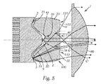
一般的に凹部201,202は、すなわちその形状および/または後方へのその広がりの長さは、右/左光導体20,30からの光が、左/右光導体30,20に入り込むことができないよう全体光出射面から離れるように構成されている。
In general, the
図5は、LED光源3の右光導体30からの優良な光線Sを示し、この光線Sは凹部202が無ければ、S’として左光導体20に入り込み、光出射面22を介して出射することとなる。部分ハイビームの場合(すなわち、LED光源2が遮断され、場合によりLED光源4が遮断される)、光が光出射面22を介して出射し、部分ハイビームを阻害ないし破壊することとなる。
FIG. 5 shows an excellent light beam S from the
しかし右光導体からの光は、左光導体と中央光導体との間の凹部/スリット202で(すなわち直線状の壁202”で)全反射され、したがって中央光導体を介して出射する(光線S”)。対応することが左光導体からの光に対しても当てはまり、この光は、右光導体と中央光導体との間の凹部/スリットで全反射され、中央光導体を介してモジュールから出射する。
However, the light from the right light guide is totally reflected at the recess /
このようにして、左/右LED光源および場合により中央LED光源が遮断される場合に、光像中に先鋭な垂直方向の明暗境界を形成することができる。 In this way, when the left / right LED light source and possibly the central LED light source are blocked, a sharp vertical light / dark boundary can be formed in the light image.
刻み目ないし凹部の深さは、側方LED光源からの光が外側の対向する光導体に達することができないように選択される。 The indentation or depth of the recess is selected so that light from the side LED light source cannot reach the outer opposing light guide.
加えてさらに、中央光導体40に対する光入力結合箇所41が、光出射面の方向に、側方LED光源からの光が凹部を通過して達することができないように前に引き出され、構成されていると合目的的である。ここで好ましくは、光入力結合箇所41は湾曲しており、たとえばLED光源4から離れるように湾曲して構成されている。したがって凹部70は全体光導体100の裏側に形成される。図示の例で光入射面41は、LED光源の光を平行に向けるレンズとしてさえも作用する。
In addition, a light
スリットによって、全ての光成分の重なり合いの中に、スリット領域内には不所望の不均一なハイビームが生じる。湾曲した壁201’,202’を使用することにより、これを光学的条件に相応に適合することができ、これにより不均一性を回避することができ、少なくとも減衰することができる。 The slit creates an undesirable non-uniform high beam in the slit area in the overlap of all light components. By using curved walls 201 ', 202', this can be adapted accordingly to the optical conditions, whereby non-uniformities can be avoided and at least attenuated.
中央LED光源4は、光像中に最大値を形成するためにそこに設けられている。これは図示の場合である。このためにLED光源4の光入力結合箇所は、光線が実質的に平行に向けられて、光最大値が光分布の中央に形成されるよう構成されている(図9参照)。 The central LED light source 4 is provided there to form a maximum value in the light image. This is the case shown. For this reason, the light input coupling portion of the LED light source 4 is configured such that the light rays are directed substantially in parallel and the maximum light value is formed at the center of the light distribution (see FIG. 9).
しかしこれは強制的ではない。もちろん、放射される光の一部分だけ、好ましくは光の中央の光強度の強い部分だけが最大値を形成し、放射される光の側方領域は幅に寄与するように入力結合箇所を構成することも考えられる。この場合は図面に示されていない。 But this is not mandatory. Of course, only a part of the emitted light, preferably only the strong part in the center of the light, forms the maximum value, and the side area of the emitted light constitutes the input coupling point to contribute to the width. It is also possible. This case is not shown in the drawing.
図5は、第1に引用した場合に対して適合されており、したがってLED光源4の光線路がここでは少し補正される。 FIG. 5 is adapted for the case cited in the first place, so that the light path of the LED light source 4 is corrected a little here.
別の図示しない変形実施形態では、凹部を、すなわちその形状および/または後方への広がりの長さを、(単数ないし複数)光出射面から離れる方向に、中央光導体群ないし少なくとも1つの中央光導体40からの光が、左光導体群ないし右光導体群または少なくとも1つの左ないし右光導体20,30に入り込むことができないよう構成することができる。
In another variant embodiment, not shown, the recesses, i.e. the shape and / or the length of the rearward extension, in the direction away from the light exit surface (s), from the central light guide group or the at least one central light. The light from the conductor 40 can be configured so that it cannot enter the left light conductor group or the right light conductor group or at least one left or
とりわけこの場合、(単数または複数)凹部との共同作用で、光線が側方光導体へ入り込むことができないように中央LED光源に対する光入力結合箇所が相応に構成されており、たとえば相応に湾曲されていることに注意すべきである。 In particular, in this case, the light input coupling point for the central LED light source is correspondingly configured, for example, correspondingly curved, so that the light rays cannot enter the side light guides in cooperation with the recess (s). It should be noted that.
この場合、中央光導体群も部分光分布に対して使用することができ、中央光導体群ないし中央光導体は、対向車が既に通過した場合にはこの対向車を幻惑することなく、スイッチオンすることができる。 In this case, the central light guide group can also be used for partial light distribution, and the central light guide group or the central light guide can be switched on without illusion of the oncoming vehicle if the oncoming vehicle has already passed. can do.
冒頭に既に述べたように、本発明のモジュールによってフェードアウトした光分布、たとえばロービーム分布もさらに付加的に形成することができるようにするため、さらに、全体光−光導体100の上方に少なくとも1つ、好ましくは2つ以上のLED光源5,6を配置することができ、これらのLED光源は光を少なくとも1つ、好ましくは2つの反射器7,8ないし光学系に放射する。反射器7,8から放射された光は、投影レンズ90の下方領域に照射され(図4)、全体光−光出射面110を画定する上方エッジ121が明暗境界としてロービームの光像中に結像される。
As already mentioned at the outset, in order to be able to further additionally form a light distribution faded out by the module according to the invention, for example a low beam distribution, at least one above the whole light-
図面に示された実施形態では反射器7,8が使用される。しかし基本的に反射器の代わりに他の適切な任意の(一次)光学系を使用することができる。 In the embodiment shown in the drawing, reflectors 7 and 8 are used. However, basically any other suitable (primary) optical system can be used instead of the reflector.
全体光−光導体100の上側120および/または下側130が、光反射性に構成されていると有利である。
Advantageously, the
たとえば上側および/または下側は、たとえば鏡面層が被覆され、たとえば蒸着されている。 For example, the upper side and / or the lower side may be coated with, for example, a mirror layer and deposited, for example.
このようにして光損失が回避され、ないし回避することができ、2つの異なる光分布が形成される場合に、これらの光分布が、漏出する光によって互いにネガティブに影響し合うことが回避される。 In this way, light loss can be avoided or avoided, and when two different light distributions are formed, these light distributions are prevented from negatively affecting each other due to leaking light. .
光分布の経過に関しては、ロービーム分布のための明暗境界を形成するために、好ましくはエッジ121が形成されており、法に則したロービーム分布(これらは図10〜12に破線により示されている)を形成するために対応する部分を有する。
With respect to the course of the light distribution, an
車両前照灯は、1つまたは好ましくは複数の上記モジュールから構成される。 The vehicle headlamp is composed of one or preferably a plurality of the above modules.
好ましくはこのような前照灯において、少なくとも1つのモジュール、好ましくは全てのモジュールが、実質的に垂直軸周りに旋回可能である。 Preferably in such a headlamp, at least one module, preferably all modules, are pivotable about a substantially vertical axis.
1つまたは複数の可動のモジュールによって、光像中の部分領域を静的に「切り出す」ことができるだけでなく、この切り出された部分領域を、モジュールの旋回によっても垂直軸周りに旋回することができる(それぞれ旋回されたモジュールが形成する全体光像により)。これにより、切り出された光部分を、対向車または先行車両の動きに応じて追従案内することができる。 Not only can one or more movable modules statically “cut out” a partial area in the optical image, but this cut out partial area can also be swiveled around the vertical axis by pivoting the module. Yes (with an overall light image formed by each swirled module). Thereby, the cut-out light portion can be guided to follow in accordance with the movement of the oncoming vehicle or the preceding vehicle.
しかし安価な実施形態では旋回を行わない、または設けないこともできる。それにもかかわらずこれにより、自動化したハイビームを、部分領域の静的なフェードアウトができない場合のように格段に早期に再作動することができる。 However, in an inexpensive embodiment, no turning can be performed or provided. Nevertheless, this makes it possible to reactivate the automated high beam much earlier, such as when partial areas cannot be statically faded out.
モジュール全体を旋回する代わりに、1つまたは複数のモジュールの投影レンズをそれぞれ1つの垂直軸周りに旋回可能にすることもできる。 Instead of pivoting the entire module, the projection lens of one or more modules can each be pivotable about one vertical axis.
ここで、旋回軸が投影レンズの焦点を通って延在すると光学的に理想的である。 Here, it is optically ideal if the pivot axis extends through the focal point of the projection lens.
図6は、LED光源モジュールの左右の光導体20,30から組み合わされた光像を示す。この光像は、法に則したハイビームを形成するのにすでに十分であり得、中央にある所要の最大値はこの領域における光像の重なり合いによって達成される。したがって最小の構成では、モジュールは1つの左LED光源と1つの右LED光源だけを有する。 FIG. 6 shows a light image combined from the left and right light guides 20 and 30 of the LED light source module. This light image may already be sufficient to form a lawful high beam, and the required maximum value in the center is achieved by the overlap of the light images in this region. Thus, in the minimum configuration, the module has only one left LED light source and one right LED light source.
任意で、図面に示すように最大値を、全体−光導体の中央にある第3のLED光源4によって高めることができる。 Optionally, the maximum value can be increased by a third LED light source 4 in the middle of the whole light guide as shown in the drawing.
図7は、本発明のLED光源モジュールの左光導体により形成された部分光像を、図8は、右光導体により形成された部分光像を、図9は、中央光導体により形成された光像を示す。 7 shows a partial light image formed by the left light conductor of the LED light source module of the present invention, FIG. 8 shows a partial light image formed by the right light conductor, and FIG. 9 shows a central light guide. An optical image is shown.
図10は、前照灯全体により形成された光分布を示す。ここで図10は具体的には、前照灯の個々のモジュールの2つのLED光源5,6により形成されたロービーム分布(概略的に破線により示されている)、並びに対応するLED光源モジュールの右光導体により形成され重ね合わされた部分ハイビームを示す。
FIG. 10 shows the light distribution formed by the entire headlamp. Here, FIG. 10 specifically shows the low beam distribution (schematically indicated by the broken lines) formed by the two
図11は、2つの前照灯により形成された全体ハイビーム分布をロービーム分布と共に示す。すなわち、全てのLED光源2,3,5,6と任意でLED光源4も作動している際の光分布である。
FIG. 11 shows the overall high beam distribution formed by the two headlamps together with the low beam distribution. That is, the light distribution when all the
最後に図12は、本発明による2つの前照灯により形成される適合型ハイビームを示す。ここで2つの前照灯は、モジュール1に関して図1〜5に示されるように同じ構造を有する。 Finally, FIG. 12 shows an adaptive high beam formed by two headlamps according to the invention. Here, the two headlamps have the same structure as shown in FIGS.
図12に示された光分布は、左前照灯においてLED光源3(そして任意でLED光源4)が作動しており、モジュールまたはそれらのレンズが左に旋回されていることによって生じる。 The light distribution shown in FIG. 12 is caused by the LED light source 3 (and optionally the LED light source 4) operating in the left headlamp and the modules or their lenses turning to the left.
基本的に各前照灯は、少なくとも1つ、通常は複数のモジュールから成る。ここで全てのモジュールは固定とすることができる。または1つのモジュールのみが、もしくは多くのモジュール(ないしはそれらのレンズ)が旋回可能であり、他のモジュールは固定的に配置することができる。好ましくは全てのモジュール(レンズ)は旋回可能である。 Basically each headlamp consists of at least one, usually a plurality of modules. Here, all modules can be fixed. Or only one module or many modules (or their lenses) can be pivoted and the other modules can be fixedly arranged. Preferably all modules (lenses) are pivotable.
ロービームユニットがハイビームユニットとは(図面の図示とは異なり)別個の場合、ロービームは旋回しないままにし、ハイビーム(部分ハイビーム)だけが対向車に追従、ないしこれに適合することができる。このような解決策は、とりわけ図に示したものよりも高価である。 If the low beam unit is separate from the high beam unit (unlike the illustration in the drawing), the low beam can be left unturned and only the high beam (partial high beam) can follow or adapt to the oncoming vehicle. Such a solution is particularly more expensive than that shown in the figure.
右前照灯では、モジュールのLED光源2(すなわち左LED光源)が作動しており(並びに任意でLED光源4、すなわち中央のLED光源)、ここでモジュールまたはレンズは、場合により軽く左に連行/旋回することができ、または固定のまま留まる。 In the right headlamp, the module's LED light source 2 (ie, the left LED light source) is activated (and optionally the LED light source 4, ie, the central LED light source), where the module or lens is optionally lightly entrained to the left / Can swivel or remain fixed.
対向交通で複数の車両が到来する場合、対向交通の際にその左に発生する全ての光分布をフェードアウトする必要が生じることがある。この場合、左前照灯において左LED光源2(そして任意で中央LED光源4)は作動させ、その光像を場合により旋回によって連行し、右前照灯においても同様に左LED光源2(そして任意で中央LED光源4)は作動させることになる。 When a plurality of vehicles arrives in oncoming traffic, it may be necessary to fade out all light distributions generated on the left side of the oncoming traffic. In this case, the left LED light source 2 (and optionally the central LED light source 4) is actuated in the left headlamp, and the light image is optionally taken by turning, and the left LED light source 2 (and optionally also in the right headlamp). The central LED light source 4) will be activated.
基本的に、2つの前照灯により形成される種々の部分光分布を任意に作動することにより、および場合により個々のモジュールの光像を旋回することにより、それぞれの交通状況(対向交通および/または自車の道路側の交通、車両数、対向車の位置...)に理想的に応答することができる。 Basically, by arbitrarily actuating the various partial light distributions formed by the two headlamps, and possibly by turning the light images of the individual modules, each traffic situation (oncoming traffic and / or Or it can respond ideally to the traffic on the road side of the vehicle, the number of vehicles, the position of the oncoming vehicle ...).
上に既に述べた複数のモジュールを使用する場合、たとえば1つ(またはレンズ)を旋回可能に構成することができ、別の1つまたは複数のモジュールは静止する。したがって右のモジュールは固定したままであり(または固定されており)、右の道路縁部を照明し(右側交通の場合)、左のモジュールは対向車と共に旋回する。 When using the modules already mentioned above, for example, one (or lens) can be configured to be pivotable, while the other module or modules are stationary. Therefore, the right module remains fixed (or is fixed), illuminates the right road edge (for right traffic), and the left module turns with the oncoming vehicle.
Claims (30)
各LED光源(2,3,4)はそれぞれ、1つまたは複数の発光ダイオードから成り、
各LED光源(2,3,4)は、それらにそれぞれ割り当てられた光入力結合箇所(21,31,41)を介して光を光導体(20,30,40)に入力結合し、
光は、前記光導体(20,30,40)から前記光導体(20,30,40)の光出射面(22,32,42)を介して出射し、
前記出射した光は、投影レンズ(90)によって、少なくとも1つの光分布を形成するために外部空間に投影される、LED投影モジュールにおいて、
個々のLED光源(2,3,4)に対する前記光導体(20,30,40)は、水平方向に横に並んで配置されており、直接互いに相接し、または1つの共通の全体光−光導体(100)を形成し、これにより隣接する光導体(20,30,40)の間で光が漏れ込むことができ、
個々の前記光出射面(22,32,42)は並置されており、かつ1つの全体光−光出射面(110)を形成し、
前記全体光−光出射面(110)内では個々の前記光出射面(22,32,42)の間に1つまたは複数の凹部(201,202)が設けられており、当該凹部はそれぞれ、前記全体光−光出射面(110)の高さ広がりの少なくとも一部分に亘って延在している、ことを特徴とするLED投影モジュール。 An LED projection module (1) comprising two or more LED light sources (2,3,4),
Each LED light source (2, 3, 4) consists of one or more light emitting diodes,
Each LED light source (2, 3, 4) couples light to the light guide (20, 30, 40) via the light input coupling points (21, 31, 41) respectively assigned to them,
The light is emitted from the light guide (20, 30, 40) via the light emission surface (22, 32, 42) of the light guide (20, 30, 40).
In the LED projection module, the emitted light is projected to an external space by a projection lens (90) to form at least one light distribution,
The light guides (20, 30, 40) for the individual LED light sources (2, 3, 4) are arranged side by side in the horizontal direction and are in direct contact with each other or one common overall light- Forming a light guide (100), whereby light can leak between adjacent light guides (20, 30, 40);
The individual light exit surfaces (22, 32, 42) are juxtaposed and form one overall light-light exit surface (110),
In the whole light-light emitting surface (110), one or a plurality of concave portions (201, 202) are provided between the individual light emitting surfaces (22, 32, 42). LED projection module, characterized in that it extends over at least part of the height spread of the overall light-light exit surface (110).
前記左および/または右光導体群はそれぞれ、所属のLED光源(2,3)を備える少なくとも1つの光導体(20,30)を含む、ことを特徴とする請求項1に記載のモジュール。 The central light guide group is provided with at least one central light guide (40), and the left and right sides of the central light guide group are provided with one left light guide group and one right light guide group, respectively.
Module according to claim 1, characterized in that each of the left and / or right light guide groups comprises at least one light guide (20, 30) comprising an associated LED light source (2, 3).
2つの光出射面(32,42;22,42)の間にある前記凹部(201,202)は、前記並置された光導体(20,30,40)の上方境界面ないし前記全体光−光導体(100)の上方境界面(120)まで完全に延在している、ことを特徴とする請求項1から7のいずれか1項に記載のモジュール。 The recesses (201, 202) between the two light exit surfaces (32, 42; 22, 42) extend to the upper boundary surface of the juxtaposed light guides (20, 30, 40) or the entire light. -It does not extend completely to the upper boundary surface (120) of the light guide (100), so that the juxtaposed light guide or the whole light-light guide (100) has a continuous edge in the upper region (121) is obtained, or the recesses (201, 202) between the two light exit surfaces (32, 42; 22, 42) are above the juxtaposed light guides (20, 30, 40). 8. Module according to any one of the preceding claims, characterized in that it extends completely from the interface to the upper interface (120) of the total light-light guide (100).
前記少なくとも1つの光学系、たとえば少なくとも1つの反射器(7,8)から放射された光が前記投影レンズ(90)の下方領域に照射され、
前記全体光−光出射面(110)を画定する上方エッジ(121)が、明暗境界として光像中に結像される、ことを特徴とする請求項1から21のいずれか1項に記載のモジュール。 At least one LED light source (5, 6) is disposed above the light guide (20, 30, 40) or the whole light-light guide (100), and the LED light source transmits light to at least one optical element. Radiate towards the system, eg reflector (7, 8),
Light emitted from the at least one optical system, for example, at least one reflector (7, 8) is irradiated to a lower region of the projection lens (90),
22. The upper edge (121) defining the overall light-light exit surface (110) is imaged in a light image as a light / dark boundary, according to any one of the preceding claims. module.
Applications Claiming Priority (3)
| Application Number | Priority Date | Filing Date | Title |
|---|---|---|---|
| ATA1724/2011 | 2011-11-22 | ||
| ATA1724/2011A AT512246B1 (en) | 2011-11-22 | 2011-11-22 | LED PROJECTION MODULE AND HEADLIGHTS WITH MODULE |
| PCT/AT2012/050173 WO2013075157A1 (en) | 2011-11-22 | 2012-11-05 | Led projection module |
Publications (2)
| Publication Number | Publication Date |
|---|---|
| JP2015501513A JP2015501513A (en) | 2015-01-15 |
| JP5939491B2 true JP5939491B2 (en) | 2016-06-22 |
Family
ID=47325742
Family Applications (1)
| Application Number | Title | Priority Date | Filing Date |
|---|---|---|---|
| JP2014537424A Active JP5939491B2 (en) | 2011-11-22 | 2012-11-05 | LED projection module |
Country Status (9)
| Country | Link |
|---|---|
| US (1) | US9611997B2 (en) |
| EP (1) | EP2748518B8 (en) |
| JP (1) | JP5939491B2 (en) |
| CN (1) | CN103946626B (en) |
| AT (1) | AT512246B1 (en) |
| BR (1) | BR112014008989A2 (en) |
| IN (1) | IN2014MN01099A (en) |
| MX (1) | MX2014006169A (en) |
| WO (1) | WO2013075157A1 (en) |
Families Citing this family (57)
| Publication number | Priority date | Publication date | Assignee | Title |
|---|---|---|---|---|
| KR101356151B1 (en) | 2011-05-23 | 2014-01-24 | 에스엘 주식회사 | Automotive headlamp system and cotrolling method for the same |
| EP2666671B1 (en) * | 2012-05-23 | 2019-10-16 | SL Corporation | Automotive headlamp system and method of controlling the same |
| AT513816B1 (en) | 2012-12-20 | 2015-11-15 | Zizala Lichtsysteme Gmbh | Light guide unit for a lighting unit of a headlamp and lighting unit and headlamp |
| WO2015004905A1 (en) * | 2013-07-10 | 2015-01-15 | 三菱電機株式会社 | Headlamp unit and headlamp |
| KR101592648B1 (en) | 2013-12-23 | 2016-02-12 | 현대자동차주식회사 | Head lamp apparatus for vehicle |
| JP6270033B2 (en) * | 2014-02-17 | 2018-01-31 | スタンレー電気株式会社 | Vehicle lighting |
| JP5888792B2 (en) * | 2014-03-18 | 2016-03-22 | 本田技研工業株式会社 | Motorcycle headlights |
| EP3173687B1 (en) | 2014-07-25 | 2021-08-25 | Stanley Electric Co., Ltd. | Lighting fixture for vehicle |
| JP6448250B2 (en) * | 2014-08-11 | 2019-01-09 | 株式会社小糸製作所 | Vehicle lighting |
| FR3026461B1 (en) * | 2014-09-30 | 2019-04-05 | Valeo Vision | LUMINOUS MODULE FOR LIGHTING AND / OR SIGNALING OF A MOTOR VEHICLE |
| JP6516495B2 (en) * | 2015-02-13 | 2019-05-22 | 株式会社小糸製作所 | Vehicle lamp |
| CN107864664B (en) * | 2015-06-09 | 2021-10-01 | 亮锐控股有限公司 | Head lamp module |
| FR3038696B1 (en) * | 2015-07-10 | 2022-02-18 | Valeo Vision | LIGHT MODULE FOR LIGHTING AND/OR SIGNALING OF A MOTOR VEHICLE |
| FR3038695A1 (en) * | 2015-07-10 | 2017-01-13 | Valeo Vision | LUMINOUS MODULE FOR LIGHTING AND / OR SIGNALING OF A MOTOR VEHICLE |
| US20170106793A1 (en) * | 2015-10-19 | 2017-04-20 | Ford Global Technologies, Llc | Vehicle lighting system with dynamic beam pattern |
| FR3042846B1 (en) * | 2015-10-23 | 2017-12-01 | Valeo Vision | LIGHT DEVICE WITH OPTICAL GUIDES |
| FR3042845B1 (en) * | 2015-10-23 | 2019-11-29 | Valeo Vision | LIGHT DEVICE WITH OPTICAL GUIDES |
| JP6595881B2 (en) * | 2015-10-27 | 2019-10-23 | スタンレー電気株式会社 | Diffuse light distribution optical system and vehicle lamp |
| DE102015224745B4 (en) * | 2015-12-09 | 2017-11-16 | Automotive Lighting Reutlingen Gmbh | Motor vehicle headlight with a base light assembly and a high beam assembly |
| AT518098B1 (en) * | 2015-12-17 | 2017-11-15 | Zkw Group Gmbh | Additional headlights for vehicles and headlight system |
| KR20170088019A (en) * | 2016-01-22 | 2017-08-01 | 현대모비스 주식회사 | Lighting apparatus for an automobile |
| FR3048065B1 (en) * | 2016-02-23 | 2019-11-29 | Valeo Vision | LIGHT-EMITTING LIGHT MODULE AND DEVICE FOR MOTOR VEHICLE |
| FR3050011A1 (en) * | 2016-04-11 | 2017-10-13 | Valeo Vision | MODULE FOR TRANSMITTING A LUMINOUS BEAM FOR MOTOR VEHICLE PROJECTOR |
| DE102016109147A1 (en) * | 2016-05-18 | 2017-11-23 | Hella Kgaa Hueck & Co. | Headlamp module with a dipped beam function and with a high beam function based on LEDs |
| DE102016109132A1 (en) * | 2016-05-18 | 2017-11-23 | Hella Kgaa Hueck & Co. | Headlight, in particular headlight of a motor vehicle |
| CN105889840B (en) * | 2016-06-08 | 2018-03-02 | 广东雷腾智能光电有限公司 | A kind of more module headlamps of adaptive distance-light one LED |
| CN106122898B (en) * | 2016-07-01 | 2019-05-03 | 广州祥明舞台灯光设备有限公司 | A kind of lens increasing light source power |
| FR3054295B1 (en) * | 2016-07-25 | 2022-08-26 | Valeo Vision | LIGHTING SYSTEM FOR LIGHTING AND/OR SIGNALING DEVICE OF A MOTOR VEHICLE |
| DE102016217130A1 (en) | 2016-09-08 | 2018-03-08 | Osram Gmbh | Optics and optical system |
| EP3327334A1 (en) * | 2016-11-24 | 2018-05-30 | Valeo Iluminacion | Automotive electronic assembly and method |
| DE102016223972A1 (en) * | 2016-12-01 | 2018-06-07 | Osram Gmbh | PRIMARY, SECONDARY, MODULE, ARRANGEMENT, VEHICLE HEADLIGHTS AND HEADLAMP SYSTEM |
| CN110023673B (en) * | 2016-12-22 | 2021-10-01 | 本田技研工业株式会社 | Vehicle headlamp |
| US11408577B2 (en) | 2017-01-12 | 2022-08-09 | Hasco Vision Technology Co., Ltd. | Transparent photoconductor having light shielding function, and application thereof |
| WO2018133250A1 (en) * | 2017-01-19 | 2018-07-26 | 上海小糸车灯有限公司 | Led light source high-beam and low-beam integrated automobile lamp module with adb function |
| AT519125B1 (en) * | 2017-01-20 | 2018-04-15 | Zkw Group Gmbh | Lighting device for a motor vehicle headlight and motor vehicle headlights |
| EP3366982B8 (en) | 2017-02-28 | 2019-08-14 | Odelo Otomotiv Aydinlatma Anonim Sirketi | A lighting apparatus and a vehicle front headlight equipped therewith |
| EP3612766B1 (en) | 2017-04-19 | 2023-08-30 | Lumileds LLC | Headlight system for a vehicle |
| DE102017119795A1 (en) * | 2017-08-29 | 2019-02-28 | HELLA GmbH & Co. KGaA | Method for controlling at least one headlight of a lighting unit for a motor vehicle, lighting unit, computer program product and computer-readable medium |
| TWI650256B (en) * | 2018-01-29 | 2019-02-11 | 誠益光電科技股份有限公司 | Smart headlight |
| EP3540296A1 (en) * | 2018-03-15 | 2019-09-18 | ZKW Group GmbH | Lighting device for a motor vehicle headlamp |
| EP3543593B1 (en) * | 2018-03-23 | 2022-05-04 | ZKW Group GmbH | Lighting device for a motor vehicle headlight |
| FR3079598B1 (en) * | 2018-03-30 | 2021-04-30 | Valeo Vision | LIGHTING MODULE WITH MULTISOURCE OPTICAL ELEMENT WITH SMOOTH EXIT FACE |
| EP3776027A4 (en) | 2018-04-02 | 2021-12-29 | Magic Leap, Inc. | Waveguides with integrated optical elements and methods of making the same |
| WO2019243246A1 (en) | 2018-06-19 | 2019-12-26 | Lumileds Holding B.V. | Operating a lighting module with led elements |
| JP6592149B2 (en) * | 2018-07-09 | 2019-10-16 | スタンレー電気株式会社 | Vehicle lighting |
| CN215863191U (en) * | 2018-08-22 | 2022-02-18 | 亮锐控股有限公司 | Optical device for automotive lighting comprising a light guide |
| DE102018125157A1 (en) * | 2018-10-11 | 2020-04-16 | HELLA GmbH & Co. KGaA | Headlights for vehicles |
| CN113286967B (en) * | 2018-12-25 | 2023-07-04 | 株式会社小糸制作所 | Optical unit |
| US10578271B1 (en) * | 2019-04-17 | 2020-03-03 | Excellence Optoelectronics Inc. | Vehicle LED linear lighting module |
| DE102019118968A1 (en) * | 2019-07-12 | 2021-01-14 | HELLA GmbH & Co. KGaA | Projection headlights for vehicles |
| US11761603B2 (en) | 2019-08-07 | 2023-09-19 | Lumileds Llc | Front-lighting system for vehicle |
| EP3896334A1 (en) * | 2020-04-14 | 2021-10-20 | ZKW Group GmbH | Lighting device for a motor vehicle headlight |
| DE202020102825U1 (en) * | 2020-05-18 | 2020-06-19 | Nimbus Group Gmbh | Asymmetrical linear lens and associated linear lamp |
| KR20220036278A (en) * | 2020-09-15 | 2022-03-22 | 현대모비스 주식회사 | Lamp for automobile and automobile including the same |
| KR102517337B1 (en) * | 2021-02-01 | 2023-04-04 | 현대모비스 주식회사 | Lamp module for vehicle and lamp for vehicle including the same |
| CN113028355B (en) * | 2021-03-23 | 2022-01-07 | 华域视觉科技(上海)有限公司 | Car light optical assembly, illumination optical device and vehicle |
| DE102022110747B3 (en) * | 2022-05-02 | 2023-11-02 | Motherson Innovations Company Limited | LIGHTING UNIT, VEHICLE COMPONENT AND VEHICLE |
Family Cites Families (24)
| Publication number | Priority date | Publication date | Assignee | Title |
|---|---|---|---|---|
| US5349504A (en) * | 1993-07-12 | 1994-09-20 | Dialight Corporation | Multi-level lightpipe design for SMD LEDs |
| US20060023461A1 (en) * | 2002-01-14 | 2006-02-02 | Richard Knight | Vehicular dynamic angle adjusted lighting |
| KR20050044894A (en) * | 2002-07-16 | 2005-05-13 | 쉐프네커 비젼 시스템즈 유에스에이 인코포레이티드 | White led headlight |
| DE102006044640A1 (en) | 2006-09-19 | 2008-03-27 | Schefenacker Vision Systems Germany Gmbh | Lighting unit for high and low beam generation |
| AT504505B1 (en) | 2006-10-23 | 2008-06-15 | Zizala Lichtsysteme Gmbh | OPTIC ELEMENT FOR A VEHICLE HEADLAMP |
| AT504668B1 (en) | 2007-01-11 | 2008-07-15 | Zizala Lichtsysteme Gmbh | TOTAL REFLECTION SYSTEM FOR A HEADLIGHT OR A LIGHT UNIT OF A MOTOR VEHICLE |
| US7677777B2 (en) * | 2007-02-21 | 2010-03-16 | Magna International, Inc. | LED apparatus for world homologation |
| JP4970136B2 (en) * | 2007-05-17 | 2012-07-04 | 株式会社小糸製作所 | Vehicle headlamp lamp unit |
| JP5091808B2 (en) * | 2008-09-02 | 2012-12-05 | 株式会社小糸製作所 | Vehicle lighting |
| DE102009008631B4 (en) * | 2009-02-12 | 2016-11-03 | Automotive Lighting Reutlingen Gmbh | Projection module for a motor vehicle headlight |
| AT508604B1 (en) * | 2009-07-31 | 2012-07-15 | Zizala Lichtsysteme Gmbh | LED MOTOR VEHICLE HEADLIGHT FOR GENERATING A DYNAMIC LIGHT DISTRIBUTION |
| DE102009053581B3 (en) * | 2009-10-05 | 2011-03-03 | Automotive Lighting Reutlingen Gmbh | Light module for a lighting device of a motor vehicle |
| JP5429478B2 (en) * | 2009-11-20 | 2014-02-26 | スタンレー電気株式会社 | Lamp |
| DE102010021937A1 (en) * | 2010-05-28 | 2011-12-01 | Hella Kgaa Hueck & Co. | LED projection module for a vehicle headlight |
| DE102010041096B4 (en) * | 2010-09-21 | 2024-05-08 | Osram Gmbh | Lighting device |
| AT510454B1 (en) | 2010-10-14 | 2013-04-15 | Zizala Lichtsysteme Gmbh | LED LIGHT VEHICLE |
| AT510930B1 (en) | 2010-12-15 | 2013-05-15 | Zizala Lichtsysteme Gmbh | LED LIGHT MODULE |
| AT510931B1 (en) | 2010-12-22 | 2013-09-15 | Zizala Lichtsysteme Gmbh | VEHICLE HEADLIGHTS WITH LED LIGHT MODULE |
| AT510437B1 (en) | 2011-02-16 | 2012-04-15 | Zizala Lichtsysteme Gmbh | LED LIGHT MODULE AND VEHICLE HEADLIGHTS |
| DE102011077636A1 (en) | 2011-04-27 | 2011-11-03 | Automotive Lighting Reutlingen Gmbh | Light module for head lamp system of motor vehicle i.e. motor car, has sub modules separately controlled to generate set of strip-shaped segments of spot distribution, where strip-shaped segments are complement to spot distribution |
| AT511499A1 (en) | 2011-05-30 | 2012-12-15 | Zizala Lichtsysteme Gmbh | VEHICLE HEADLAMP WITH LED LIGHT MODULES FOR GENERATING A MAIN LIGHT DISTRIBUTION AND AN ADDITIONAL LIGHT DISTRIBUTION |
| AT511760B1 (en) | 2011-08-08 | 2013-12-15 | Zizala Lichtsysteme Gmbh | LED LIGHT SOURCE MODULE FOR A LED MOTOR VEHICLE HEADLIGHT AND LED MOTOR VEHICLE HEADLAMP AND HEADLAMP SYSTEM |
| AT511761B1 (en) | 2011-08-08 | 2014-02-15 | Zizala Lichtsysteme Gmbh | LED LIGHT SOURCE MODULE FOR A VEHICLE HEADLAMP AND VEHICLE HEADLAMP AND VEHICLE LIGHT SYSTEM |
| AT512056B1 (en) | 2011-11-08 | 2013-05-15 | Zizala Lichtsysteme Gmbh | LIGHTING ELEMENT AND LIGHT UNIT |
-
2011
- 2011-11-22 AT ATA1724/2011A patent/AT512246B1/en not_active IP Right Cessation
-
2012
- 2012-11-05 CN CN201280057436.3A patent/CN103946626B/en active Active
- 2012-11-05 JP JP2014537424A patent/JP5939491B2/en active Active
- 2012-11-05 IN IN1099MUN2014 patent/IN2014MN01099A/en unknown
- 2012-11-05 BR BR112014008989A patent/BR112014008989A2/en not_active IP Right Cessation
- 2012-11-05 EP EP12798591.9A patent/EP2748518B8/en active Active
- 2012-11-05 WO PCT/AT2012/050173 patent/WO2013075157A1/en active Application Filing
- 2012-11-05 MX MX2014006169A patent/MX2014006169A/en active IP Right Grant
- 2012-11-05 US US14/359,399 patent/US9611997B2/en active Active
Also Published As
| Publication number | Publication date |
|---|---|
| EP2748518B8 (en) | 2016-12-14 |
| BR112014008989A2 (en) | 2017-05-02 |
| US20140321141A1 (en) | 2014-10-30 |
| MX2014006169A (en) | 2014-06-19 |
| AT512246B1 (en) | 2014-02-15 |
| EP2748518B1 (en) | 2016-09-21 |
| CN103946626B (en) | 2017-05-10 |
| IN2014MN01099A (en) | 2015-07-03 |
| JP2015501513A (en) | 2015-01-15 |
| WO2013075157A1 (en) | 2013-05-30 |
| EP2748518A1 (en) | 2014-07-02 |
| AT512246A1 (en) | 2013-06-15 |
| CN103946626A (en) | 2014-07-23 |
| US9611997B2 (en) | 2017-04-04 |
Similar Documents
| Publication | Publication Date | Title |
|---|---|---|
| JP5939491B2 (en) | LED projection module | |
| EP2693105B1 (en) | Vehicle lighting unit | |
| US9506615B2 (en) | Motor vehicle headlamp having a multi-function projection module | |
| JP5091808B2 (en) | Vehicle lighting | |
| KR100934682B1 (en) | Luminaire Units for Vehicle Headlights | |
| US9316374B2 (en) | Vehicle headlight | |
| JP2017174737A (en) | Vehicular lighting fixture and vehicle including vehicular lighting fixture | |
| JP2017174736A (en) | Vehicular lighting fixture and vehicle including vehicular lighting fixture | |
| KR101393659B1 (en) | Vehicular headlamp | |
| JP2015526868A (en) | Headlight lighting device | |
| CN108240603A (en) | LED module and the lighting device with multiple this LED modules for motor vehicle | |
| KR20120117651A (en) | Vehicular lamp | |
| US11603972B2 (en) | Light guide for vehicles, and lamp for vehicles | |
| CZ305372B6 (en) | Motor vehicle headlight | |
| JP5640306B2 (en) | Lamp unit | |
| JP5457925B2 (en) | Vehicle lighting | |
| JP6967396B2 (en) | Vehicle lighting | |
| JP2005251435A (en) | Vehicular headlight | |
| US20150267895A1 (en) | Lighting unit | |
| JP2015082339A (en) | Vehicular lighting fixture | |
| WO2022092255A1 (en) | Vehicular headlamp | |
| WO2021141052A1 (en) | Vehicle lighting tool | |
| KR20190048547A (en) | Lamp for vehicle | |
| JP2021111446A (en) | Vehicular lighting fixture | |
| KR20150072623A (en) | Lamp for vehicle |
Legal Events
| Date | Code | Title | Description |
|---|---|---|---|
| A521 | Request for written amendment filed |
Free format text: JAPANESE INTERMEDIATE CODE: A523 Effective date: 20141024 |
|
| A131 | Notification of reasons for refusal |
Free format text: JAPANESE INTERMEDIATE CODE: A131 Effective date: 20150106 |
|
| A521 | Request for written amendment filed |
Free format text: JAPANESE INTERMEDIATE CODE: A523 Effective date: 20150318 |
|
| A521 | Request for written amendment filed |
Free format text: JAPANESE INTERMEDIATE CODE: A523 Effective date: 20150417 |
|
| A131 | Notification of reasons for refusal |
Free format text: JAPANESE INTERMEDIATE CODE: A131 Effective date: 20150623 |
|
| A601 | Written request for extension of time |
Free format text: JAPANESE INTERMEDIATE CODE: A601 Effective date: 20150917 |
|
| A521 | Request for written amendment filed |
Free format text: JAPANESE INTERMEDIATE CODE: A523 Effective date: 20151008 |
|
| A521 | Request for written amendment filed |
Free format text: JAPANESE INTERMEDIATE CODE: A523 Effective date: 20151120 |
|
| TRDD | Decision of grant or rejection written | ||
| A01 | Written decision to grant a patent or to grant a registration (utility model) |
Free format text: JAPANESE INTERMEDIATE CODE: A01 Effective date: 20160412 |
|
| A61 | First payment of annual fees (during grant procedure) |
Free format text: JAPANESE INTERMEDIATE CODE: A61 Effective date: 20160506 |
|
| R150 | Certificate of patent or registration of utility model |
Ref document number: 5939491 Country of ref document: JP Free format text: JAPANESE INTERMEDIATE CODE: R150 |
|
| S531 | Written request for registration of change of domicile |
Free format text: JAPANESE INTERMEDIATE CODE: R313531 |
|
| S533 | Written request for registration of change of name |
Free format text: JAPANESE INTERMEDIATE CODE: R313533 |
|
| R350 | Written notification of registration of transfer |
Free format text: JAPANESE INTERMEDIATE CODE: R350 |
|
| R250 | Receipt of annual fees |
Free format text: JAPANESE INTERMEDIATE CODE: R250 |
|
| R250 | Receipt of annual fees |
Free format text: JAPANESE INTERMEDIATE CODE: R250 |
|
| R250 | Receipt of annual fees |
Free format text: JAPANESE INTERMEDIATE CODE: R250 |
|
| R250 | Receipt of annual fees |
Free format text: JAPANESE INTERMEDIATE CODE: R250 |
|
| R250 | Receipt of annual fees |
Free format text: JAPANESE INTERMEDIATE CODE: R250 |
|
| R250 | Receipt of annual fees |
Free format text: JAPANESE INTERMEDIATE CODE: R250 |