EP2693105B1 - Vehicle lighting unit - Google Patents
Vehicle lighting unit Download PDFInfo
- Publication number
- EP2693105B1 EP2693105B1 EP13020058.7A EP13020058A EP2693105B1 EP 2693105 B1 EP2693105 B1 EP 2693105B1 EP 13020058 A EP13020058 A EP 13020058A EP 2693105 B1 EP2693105 B1 EP 2693105B1
- Authority
- EP
- European Patent Office
- Prior art keywords
- light
- guiding lens
- reflection surface
- light guiding
- drl
- Prior art date
- Legal status (The legal status is an assumption and is not a legal conclusion. Google has not performed a legal analysis and makes no representation as to the accuracy of the status listed.)
- Active
Links
- 230000002093 peripheral effect Effects 0.000 claims description 5
- 230000003287 optical effect Effects 0.000 description 14
- XAGFODPZIPBFFR-UHFFFAOYSA-N aluminium Chemical compound [Al] XAGFODPZIPBFFR-UHFFFAOYSA-N 0.000 description 5
- 229910052782 aluminium Inorganic materials 0.000 description 5
- 230000008021 deposition Effects 0.000 description 5
- 238000010586 diagram Methods 0.000 description 4
- 239000000758 substrate Substances 0.000 description 2
- 230000002411 adverse Effects 0.000 description 1
- 230000015572 biosynthetic process Effects 0.000 description 1
- 230000006866 deterioration Effects 0.000 description 1
- 230000002708 enhancing effect Effects 0.000 description 1
Images


Classifications
-
- F—MECHANICAL ENGINEERING; LIGHTING; HEATING; WEAPONS; BLASTING
- F21—LIGHTING
- F21S—NON-PORTABLE LIGHTING DEVICES; SYSTEMS THEREOF; VEHICLE LIGHTING DEVICES SPECIALLY ADAPTED FOR VEHICLE EXTERIORS
- F21S41/00—Illuminating devices specially adapted for vehicle exteriors, e.g. headlamps
- F21S41/10—Illuminating devices specially adapted for vehicle exteriors, e.g. headlamps characterised by the light source
- F21S41/14—Illuminating devices specially adapted for vehicle exteriors, e.g. headlamps characterised by the light source characterised by the type of light source
- F21S41/141—Light emitting diodes [LED]
- F21S41/147—Light emitting diodes [LED] the main emission direction of the LED being angled to the optical axis of the illuminating device
-
- B—PERFORMING OPERATIONS; TRANSPORTING
- B60—VEHICLES IN GENERAL
- B60Q—ARRANGEMENT OF SIGNALLING OR LIGHTING DEVICES, THE MOUNTING OR SUPPORTING THEREOF OR CIRCUITS THEREFOR, FOR VEHICLES IN GENERAL
- B60Q1/00—Arrangement of optical signalling or lighting devices, the mounting or supporting thereof or circuits therefor
- B60Q1/0029—Spatial arrangement
- B60Q1/0041—Spatial arrangement of several lamps in relation to each other
- B60Q1/0058—Stacked, i.e. one lamp located behind the other in the optical axis direction
-
- F—MECHANICAL ENGINEERING; LIGHTING; HEATING; WEAPONS; BLASTING
- F21—LIGHTING
- F21S—NON-PORTABLE LIGHTING DEVICES; SYSTEMS THEREOF; VEHICLE LIGHTING DEVICES SPECIALLY ADAPTED FOR VEHICLE EXTERIORS
- F21S41/00—Illuminating devices specially adapted for vehicle exteriors, e.g. headlamps
- F21S41/10—Illuminating devices specially adapted for vehicle exteriors, e.g. headlamps characterised by the light source
- F21S41/14—Illuminating devices specially adapted for vehicle exteriors, e.g. headlamps characterised by the light source characterised by the type of light source
- F21S41/141—Light emitting diodes [LED]
- F21S41/143—Light emitting diodes [LED] the main emission direction of the LED being parallel to the optical axis of the illuminating device
-
- F—MECHANICAL ENGINEERING; LIGHTING; HEATING; WEAPONS; BLASTING
- F21—LIGHTING
- F21S—NON-PORTABLE LIGHTING DEVICES; SYSTEMS THEREOF; VEHICLE LIGHTING DEVICES SPECIALLY ADAPTED FOR VEHICLE EXTERIORS
- F21S41/00—Illuminating devices specially adapted for vehicle exteriors, e.g. headlamps
- F21S41/20—Illuminating devices specially adapted for vehicle exteriors, e.g. headlamps characterised by refractors, transparent cover plates, light guides or filters
- F21S41/24—Light guides
-
- F—MECHANICAL ENGINEERING; LIGHTING; HEATING; WEAPONS; BLASTING
- F21—LIGHTING
- F21S—NON-PORTABLE LIGHTING DEVICES; SYSTEMS THEREOF; VEHICLE LIGHTING DEVICES SPECIALLY ADAPTED FOR VEHICLE EXTERIORS
- F21S41/00—Illuminating devices specially adapted for vehicle exteriors, e.g. headlamps
- F21S41/20—Illuminating devices specially adapted for vehicle exteriors, e.g. headlamps characterised by refractors, transparent cover plates, light guides or filters
- F21S41/25—Projection lenses
- F21S41/265—Composite lenses; Lenses with a patch-like shape
-
- F—MECHANICAL ENGINEERING; LIGHTING; HEATING; WEAPONS; BLASTING
- F21—LIGHTING
- F21S—NON-PORTABLE LIGHTING DEVICES; SYSTEMS THEREOF; VEHICLE LIGHTING DEVICES SPECIALLY ADAPTED FOR VEHICLE EXTERIORS
- F21S41/00—Illuminating devices specially adapted for vehicle exteriors, e.g. headlamps
- F21S41/20—Illuminating devices specially adapted for vehicle exteriors, e.g. headlamps characterised by refractors, transparent cover plates, light guides or filters
- F21S41/25—Projection lenses
- F21S41/27—Thick lenses
-
- F—MECHANICAL ENGINEERING; LIGHTING; HEATING; WEAPONS; BLASTING
- F21—LIGHTING
- F21S—NON-PORTABLE LIGHTING DEVICES; SYSTEMS THEREOF; VEHICLE LIGHTING DEVICES SPECIALLY ADAPTED FOR VEHICLE EXTERIORS
- F21S41/00—Illuminating devices specially adapted for vehicle exteriors, e.g. headlamps
- F21S41/20—Illuminating devices specially adapted for vehicle exteriors, e.g. headlamps characterised by refractors, transparent cover plates, light guides or filters
- F21S41/25—Projection lenses
- F21S41/275—Lens surfaces, e.g. coatings or surface structures
-
- F—MECHANICAL ENGINEERING; LIGHTING; HEATING; WEAPONS; BLASTING
- F21—LIGHTING
- F21S—NON-PORTABLE LIGHTING DEVICES; SYSTEMS THEREOF; VEHICLE LIGHTING DEVICES SPECIALLY ADAPTED FOR VEHICLE EXTERIORS
- F21S41/00—Illuminating devices specially adapted for vehicle exteriors, e.g. headlamps
- F21S41/20—Illuminating devices specially adapted for vehicle exteriors, e.g. headlamps characterised by refractors, transparent cover plates, light guides or filters
- F21S41/285—Refractors, transparent cover plates, light guides or filters not provided in groups F21S41/24-F21S41/28
-
- F—MECHANICAL ENGINEERING; LIGHTING; HEATING; WEAPONS; BLASTING
- F21—LIGHTING
- F21S—NON-PORTABLE LIGHTING DEVICES; SYSTEMS THEREOF; VEHICLE LIGHTING DEVICES SPECIALLY ADAPTED FOR VEHICLE EXTERIORS
- F21S41/00—Illuminating devices specially adapted for vehicle exteriors, e.g. headlamps
- F21S41/30—Illuminating devices specially adapted for vehicle exteriors, e.g. headlamps characterised by reflectors
- F21S41/32—Optical layout thereof
- F21S41/322—Optical layout thereof the reflector using total internal reflection
-
- F—MECHANICAL ENGINEERING; LIGHTING; HEATING; WEAPONS; BLASTING
- F21—LIGHTING
- F21S—NON-PORTABLE LIGHTING DEVICES; SYSTEMS THEREOF; VEHICLE LIGHTING DEVICES SPECIALLY ADAPTED FOR VEHICLE EXTERIORS
- F21S43/00—Signalling devices specially adapted for vehicle exteriors, e.g. brake lamps, direction indicator lights or reversing lights
- F21S43/10—Signalling devices specially adapted for vehicle exteriors, e.g. brake lamps, direction indicator lights or reversing lights characterised by the light source
- F21S43/13—Signalling devices specially adapted for vehicle exteriors, e.g. brake lamps, direction indicator lights or reversing lights characterised by the light source characterised by the type of light source
- F21S43/14—Light emitting diodes [LED]
-
- F—MECHANICAL ENGINEERING; LIGHTING; HEATING; WEAPONS; BLASTING
- F21—LIGHTING
- F21S—NON-PORTABLE LIGHTING DEVICES; SYSTEMS THEREOF; VEHICLE LIGHTING DEVICES SPECIALLY ADAPTED FOR VEHICLE EXTERIORS
- F21S43/00—Signalling devices specially adapted for vehicle exteriors, e.g. brake lamps, direction indicator lights or reversing lights
- F21S43/20—Signalling devices specially adapted for vehicle exteriors, e.g. brake lamps, direction indicator lights or reversing lights characterised by refractors, transparent cover plates, light guides or filters
- F21S43/26—Refractors, transparent cover plates, light guides or filters not provided in groups F21S43/235 - F21S43/255
-
- F—MECHANICAL ENGINEERING; LIGHTING; HEATING; WEAPONS; BLASTING
- F21—LIGHTING
- F21S—NON-PORTABLE LIGHTING DEVICES; SYSTEMS THEREOF; VEHICLE LIGHTING DEVICES SPECIALLY ADAPTED FOR VEHICLE EXTERIORS
- F21S43/00—Signalling devices specially adapted for vehicle exteriors, e.g. brake lamps, direction indicator lights or reversing lights
- F21S43/30—Signalling devices specially adapted for vehicle exteriors, e.g. brake lamps, direction indicator lights or reversing lights characterised by reflectors
- F21S43/31—Optical layout thereof
- F21S43/315—Optical layout thereof using total internal reflection
-
- F—MECHANICAL ENGINEERING; LIGHTING; HEATING; WEAPONS; BLASTING
- F21—LIGHTING
- F21S—NON-PORTABLE LIGHTING DEVICES; SYSTEMS THEREOF; VEHICLE LIGHTING DEVICES SPECIALLY ADAPTED FOR VEHICLE EXTERIORS
- F21S43/00—Signalling devices specially adapted for vehicle exteriors, e.g. brake lamps, direction indicator lights or reversing lights
- F21S43/40—Signalling devices specially adapted for vehicle exteriors, e.g. brake lamps, direction indicator lights or reversing lights characterised by the combination of reflectors and refractors
-
- B—PERFORMING OPERATIONS; TRANSPORTING
- B60—VEHICLES IN GENERAL
- B60Q—ARRANGEMENT OF SIGNALLING OR LIGHTING DEVICES, THE MOUNTING OR SUPPORTING THEREOF OR CIRCUITS THEREFOR, FOR VEHICLES IN GENERAL
- B60Q2400/00—Special features or arrangements of exterior signal lamps for vehicles
- B60Q2400/30—Daytime running lights [DRL], e.g. circuits or arrangements therefor
-
- F—MECHANICAL ENGINEERING; LIGHTING; HEATING; WEAPONS; BLASTING
- F21—LIGHTING
- F21S—NON-PORTABLE LIGHTING DEVICES; SYSTEMS THEREOF; VEHICLE LIGHTING DEVICES SPECIALLY ADAPTED FOR VEHICLE EXTERIORS
- F21S41/00—Illuminating devices specially adapted for vehicle exteriors, e.g. headlamps
- F21S41/30—Illuminating devices specially adapted for vehicle exteriors, e.g. headlamps characterised by reflectors
- F21S41/32—Optical layout thereof
- F21S41/36—Combinations of two or more separate reflectors
- F21S41/365—Combinations of two or more separate reflectors successively reflecting the light
Definitions
- the present invention relates to a vehicle lighting unit for use in, for example, a vehicle headlamp, as known from EP 2 093 480 A2 .
- vehicle headlamps to be mounted on a front portion of a vehicle body, which can include daytime running lamps (DRL) for improving conspicuousness of an automobile during daytime running in addition to the basic headlamp functions for forming a high beam (travelling beam) and a low beam (passing-by beam).
- DRL daytime running lamps
- the vehicle headlamps having such a DRL function can include a DRL-dedicated optical system for controlling the light distribution for DRL in addition to the common optical system for a headlamp function.
- a vehicle headlamp including a lamp unit for a headlamp function, composed of a light source and a lens.
- the vehicle headlamp can separately include another lamp unit for achieving a DRL function, composed of a second light source and a second lens. In this vehicle headlamp, the lamp units can be controlled separately.
- U.S. Patent No. 7,460,985 discloses a vehicle headlamp including a plurality of lamp units to form a low beam (passing-by beam).
- the lens for the headlamp function and the second lens for the DRL function must be exposed on the front of the vehicle body in order to project light beams through both the lenses. This may enlarge the light emission unit of the entire headlamp when compared with headlamps without a DRL function.
- the too-large light emission unit may lead to the large-sized lighting unit as well as deterioration of design degree of freedom.
- a vehicle headlamp for use in a sports car is required to be miniaturized for the purpose of enhancing design degree of freedom. This means such a conventional vehicle headlamp with the above-described configuration cannot meet the demand.
- a vehicle lighting unit that can include a DRL function while the light emission unit thereof can be miniaturized more than the conventional vehicle headlamps.
- a vehicle lighting unit can include a first light source; a light guiding lens provided forward of the first light source, configured to project light emitted from the first light source forward to form a high beam or a low beam; and a DRL unit including a second light source, configured to function as a daytime running lamp.
- the light guiding lens can include: a front surface; a rear surface; a light incident surface located in front of the first light source, configured to allow the light emitted from the first light source to enter the light guiding lens therethrough; a front reflection surface formed in the front surface, located in front of the light incident surface, the front reflection surface configured to internally reflect the light having entered the light guiding lens through the light incident surface to a direction obliquely rearward and toward one side (for example, downward) with respect to a direction (for example, vertical direction) approximately perpendicular to a front-rear direction; a rear reflection surface formed in the rear surface, located at a portion of the rear surface in the direction obliquely rearward and toward the one side with respect to the front reflection surface, the rear reflection surface configured to internally and forwardly reflect the light having been reflected by the front reflection surface; a light exiting surface formed in the front surface, located in front of the rear reflection surface, the light exiting surface configured to allow the light having been reflected by the rear
- the light guiding lens configured to form a high beam or a low beam i.e., the light guiding lens for the headlamp function
- the light guiding lens for the headlamp function can include a light-transmitting section between the front reflection surface and the rear reflection surface in terms of the vertical direction, with these reflection surfaces configured to allow light to control light distribution.
- the DRL unit configured to function as a daytime running lamp can be located behind the light-transmitting section, so that the light from the DRL unit can pass through the light-transmitting section to be projected forward. This can eliminate the exposure of the DRL unit at a front portion of a vehicle body while the light from the DRL unit can be projected forward.
- the light emission unit can be miniaturized more than the conventional vehicle headlamp in which two types of lenses for the headlamp function and the DRL function are exposed at a front portion of a vehicle body.
- the vehicle lighting unit according to the present invention can effectively exhibit the DRL function while the light emission unit can be miniaturized more than the conventional one.
- the light-transmitting section configured to allow the light from the DRL unit to pass therethrough can be disposed between the front reflection surface configured to internally reflect light obliquely rearward and downward, for example, and the rear reflection surface configured to internally reflect the light from the front reflection surface forward in terms of the vertical direction.
- the light exiting surface of the light guiding lens being the light emission unit when functioning as a headlamp and the light-transmitting section of the light guiding lens being the light emission unit when functioning as a DRL can be located adjacent to each other within the same light guiding lens. Therefore, the light emission units during the operation of the respective lamp functions can be observed with a similar sense when compared with the case where a conventional headlamp with a DRL unit separately operates the light emission units through two separate light guiding lenses.
- the DRL unit can be configured so as to emit part of light to a portion of the light guiding lens toward a second side opposite to the first side where the light-transmitting section is located.
- the part of light can enter the light guiding lens and can be internally reflected by the front reflection surface and then the rear reflection surface to exit through the light exiting surface forward.
- the DRL unit can include a second light guiding lens disposed in front of the second light source.
- the second light guiding lens can include:
- the light incident portion of the second light guiding lens can include:
- the center light guiding portion of the second light guiding lens can include:
- the lateral light guiding portion of the second light guiding lens can include:
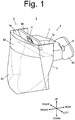
- Fig. 1 is a perspective view of a vehicle lighting unit 1 serving as a vehicle headlamp.
- Fig. 2 is a vertical cross-sectional view of the vehicle lighting unit of the present exemplary embodiment at its horizontal center.
- the directions of “front (forward),” “back (rear, rearward),” “left,” “right,” “up,” and “down (low)” mean the directions when viewed with respect to the vehicle lighting unit 1 installed in a vehicle body to project light forward of the vehicle body.
- the vehicle lighting unit 1 can be installed onto a front portion of a vehicle body (not shown), so as to function as a headlamp (hereinafter, referred to as "HL”) to form a low beam or a high beam while functioning as a daytime running lamp (hereinafter, referred to as "DRL”) to be lit during the daytime travelling.
- the vehicle lighting unit 1 can include an HL unit 2 functioning mainly as HL and a DRL unit 3 functioning as DRL.
- the HL unit 2 can include an HL light emitting diode (LED) 4 and an HL light guiding lens 5.
- LED HL light emitting diode
- the HL LED 4 can serve as the first light source in the claims and be mounted on the front surface of a substrate 40 so that its light emission surface is directed obliquely forward and downward.
- the HL light guiding lens 5 can serve as the light guiding lens in the claims and can control the light emitted from the HL LED 4 to project the light forward, thereby forming a low beam or a high beam in front of the vehicle body.
- the HL light guiding lens 5 can be formed in a rectangular shape when viewed from its front side, and can have a cut-out section 5a having an approximately L-shape cross-section at its top and extending rearward.
- the HL LED 4 can be housed within the cut-out section 5a so that the HL light guiding lens 5 as a whole can be located forward of the HL LED 4.
- the front surface within the cut-out section 5a can serve as a light incident surface 51 so that the light emitted from the HL LED 4 can impinge on the light incident surface 51 to enter the HL light guiding lens 5.
- the light incident surface 51 can be located in front of, and obliquely below, the HL LED 4 and have a surface inclined rearward and upward so as to face to the HL LED 4.
- the front surface of the HL light guiding lens 5 can be curved while being convex forward when viewed as a plan view and being inclined forward when viewed in a lateral view.
- the front surface can have an upper portion in front of the light incident surface 51 being subjected to mirror finishing such as aluminum deposition.
- the upper portion can serve as a front reflection surface 52 configured to internally reflect the light having entered the HL light guiding lens 5 through the light incident surface 51 to a direction obliquely rearward and downward.
- the front surface can have a lower portion serving as a light exiting surface 53 configured to allow the light to be projected therethrough forward from the inside of the HL light guiding lens 5.
- the light exiting surface 53 can be located in front of a rear reflection surface 54 to be described later, and configured to allow the light having been internally reflected by the rear reflection surface 54 to be projected from the HL light guiding lens 5.
- the portion of the front surface of the HL light guiding lens 5 other than the front reflection surface 52 is not required to be subjected to mirror finishing such as aluminum deposition. This is because the light entering through the light incident surface 51 can impinge thereon at an angle of incidence greater than the critical angle, thereby being reflected obliquely rearward and downward as in the front reflection surface 52.
- the HL light guiding lens 5 can have a rear surface below the cut-out portion 5a so that the rear surface can be curved while being inclined forward with a greater gradient than that of the front surface (see Fig. 2 ).
- the portion of the rear surface located below and obliquely rearward of the front reflection surface 52 and in the rear of the light exiting surface 53 can serve as the rear reflection surface 54 configured to internally and forwardly reflect the light having been internally reflected by the front surface.
- the rear reflection surface 54 can be subjected to mirror finishing such as aluminum deposition. Specifically, the rear reflection surface 54 can be configured to internally and forwardly reflect the light having been internally reflected by the front surface of the HL light guiding lens 5 while collimating the light approximately along the front-rear direction when viewed as a lateral side view.
- the see-through portion can have a vertical length, for example, approximately 3 mm.
- the see-through portion is not subjected to mirror finishing such as aluminum deposition, so that the see-through portion can serve as the light-transmitting section 55 through which the light can pass forward.
- the front surface of the light-transmitting section 55 can internally reflect the light from the light incident surface 51 obliquely rearward and downward as in the front reflection surface 52.
- the light-transmitting section 55 corresponds to a portion that is not utilized as the front and rear reflection surfaces 52 and 54 due to the rearward inclination of the HL light guiding lens 5.
- the front surface of that portion can internally reflect the light from the light incident surface 51 without aluminum deposition while the light internally reflected by the front reflection surface 52 cannot impinge on the rear surface of that portion.
- the DRL unit 3 can be disposed in the rear of the light-transmitting section 55 of the HL light guiding lens 5, and can include a DRL LED 6 and a DRL light guiding lens 7.
- the DRL LED 6 can serve as the second light source in the claims and can be mounted on the front surface of a substrate 60 so that its light emission surface is directed forward while its optical axis Ax is aligned with the front-rear direction.
- the DRL light guiding lens 7 can serve as the second light guiding lens in the claims and be disposed in front of the DRL LED 6, so as to control the light emitted from the DRL LED 6 to project the light forward with a controlled light distribution.
- Figs. 3A, 3B, 3C, and 3D are diagrams illustrating the DRL light guiding lens 7, 3A a perspective view thereof, 3B a front view thereof, 3C a horizontal cross-sectional view thereof taken along II-II line of Fig. 3B, and 3D a vertical cross-sectional view thereof taken along III-III line of Fig. 3B .
- the DRL light guiding lens 7 can be shaped horizontally long with a width approximately equal to that of the HL light guiding lens 5.
- the DRL light guiding lens 7 can include a light incident portion 71 at the rear center thereof that can receive the light emitted from the DRL LED 6.
- the light incident portion 71 can be formed in a truncated conical shape with its optical axis Ax as a rotation symmetric axis directed rearward. At the rearmost end of the light incident portion 71, there can be provided a concave portion 71a opened rearward.
- the bottom of the concave portion 71a can serve as a first light incident surface 711 having an aspherical convex shape rearward with the optical axis Ax as a rotation symmetric axis so that the first light incident surface 711 is opposite to the DRL LED 6.
- the first light incident surface 711 can have a focal point at or near which the DRL LED 6 is disposed.
- the light emitted forward from the DRL LED 6 can enter the DRL light guiding lens 7 through the first light incident surface 711 while being collimated approximately along the front-rear direction by the same.
- the inner peripheral surface of the concave portion 71a can serve as a second light incident surface 712.
- the second light incident surface 712 can be a truncated conical surface extending from the peripheral edge of the first light incident surface 711 rearward so as to cover the front periphery of the DRL LED 6.
- the thus configured second light incident surface 712 can receive the light emitted outwardly from the DRL LED 6 to allow the light to enter the DRL light guiding lens 7.
- the outer peripheral surface of the light incident portion 71 can serve as a first reflection surface 713.
- the first reflection surface 713 can be a truncated conical surface extending from the tip (rear tip end) of the second light incident surface 712 while expanding forward and outward (away from the optical axis Ax).
- the thus configured first reflection surface 713 can internally reflect the light having entered the DRL light guiding lens 7 from the second light incident surface 712 so as to collimate the light approximately along the front-rear direction.
- a recessed portion 71 opened upward.
- the portion of the DRL light guiding lens 7 below the recessed portion 7a can serve as a center light guiding portion 72 that can guide part of the light having entered the DRL light guiding lens 7 from the light incident portion 71 to the horizontal center of the front surface of the DRL light guiding lens 7 to project the light forward.
- the lower surface of the center light guiding portion 72 at its front end portion can serve as a planar second reflection surface 721 inclined forward and upward at an angle of inclination of 45 degrees, for example.
- the second reflection surface 721 can be located in front of part of the lower light incident portion 71, so that the second reflection surface 721 can internally and upwardly reflect part of the light having entered the DRL light guiding lens 7 from the light incident portion 71 and guided by the center light guiding portion 72.
- the upper surface of the center light guiding portion 72 at its front end portion can serve as a planar third reflection surface 722 in parallel with the second reflection surface 721.
- the third reflection surface 722 can be located above the second reflection surface 721 and in the rear of the horizontal center part of the light-transmitting section 55 of the HL light guiding lens 5.
- the third reflection surface 722 can internally and forwardly reflect the light having been internally reflected by the second reflection surface 721.
- the front surface of the center light guiding portion 72 can serve as a planar center light exiting surface 723 approximately perpendicular to the front-rear direction.
- the center light exiting surface 723 can be located in front of the third reflection surface 722, or in the rear of the horizontal center of the light-transmitting section 55 of the HL light guiding lens 5.
- the center light exiting surface 723 can allow the light having been internally reflected by the third reflection surface 722 to be projected forward toward the horizontal center of the light-transmitting section 55.
- the third reflection surface 722 and the center light exiting surface 723 can be provided to cover (correspond to) the light-transmitting section 55 of the HL light guiding lens 5 with a slightly larger size thereof in the vertical direction. (See Fig. 2 .) Accordingly, part of the light having been internally reflected by the third reflection surface 722 and exiting through the center light exiting surface 723 can impinge on the area of the HL light guiding lens 5 above the light-transmitting section 55 to enter the HL light guiding lens 5 and be internally reflected by the front reflection surface 52.
- the DRL light guiding lens 7 can include lateral light guiding portions 73 on both sides of the center light guiding portion 72.
- the lateral light guiding portions 73 can be configured to guide upper part of the light having entered the DRL light guiding lens 7 through the light incident portion 71 to be projected forward through the left and right front surface portions of the DRL light guiding lens 7.
- each of the lateral light guiding portions 73 can include a fourth reflection surface 731, a fifth reflection surface 732, and a lateral light exiting surface 733.
- the fourth reflection surface 731 is a rear side of the recessed portion 7a and can be located in front of the upper part of the light incident portion 71.
- the fourth reflection surfaces 731 can be a pair of planes inclined laterally at an angle of inclination of 45 degrees, for example, with respect to the optical axis Ax and a boundary line vertically extending and passing the optical axis Ax.
- the fourth reflection surfaces 731 can internally reflect part of the light having entered the DRL light guiding lens 7 from the light incident portion 71 except for the part of the light to be guided through the center light guiding portion 72, so that the reflected light can be directed laterally (in the left and right directions) with respect to the optical axis Ax.
- the fifth reflection surface 732 can include a plurality of reflection surfaces (732) provided on the rear surface of the DRL light guiding lens 7 on the left and right sides of the light incident portion 71.
- the portions on the left and right sides of the light incident portion 71 can be formed in an approximately step shape having step surfaces 73a.
- the step surfaces 73a can be located forward as the step surfaces 73a are away from the optical axis Ax in the left and right directions.
- the respective fifth reflection surfaces 732 can be formed as a plane in parallel with a nearer one of the pair of the fourth reflection surfaces 731.
- the respective fifth reflection surfaces 732 and the step surfaces 73a can be alternately continued to form the stepped surface as a whole.
- the plurality of the fifth reflection surfaces 732 can be located away from the pair of the fourth reflection surfaces 731 in the left and right directions while being located in the rear of the light transmitting section 55 of the HL light guiding lens 5 on its left and right side areas.
- the thus configured fifth reflection surfaces 732 can internally reflect the light having been internally reflected by the pair of the fourth reflection surfaces 731 in the left and right directions.
- the lateral light exiting surface 733 can be shaped in a plane shape approximately perpendicular to the front-rear direction and disposed on either side of the center light exiting surface 723.
- the lateral light exiting surfaces 733 can be located in front of the plurality of the fifth reflection surfaces 732, or in other words, can be located in the rear of the light transmitting section 55 of the HL light guiding lens 5 on its left and right side areas. Accordingly, the light having been internally reflected by the plurality of the fifth reflection surfaces 732 can be allowed to pass through the lateral light exiting surfaces 733 toward the left and right side areas of the light-transmitting section 55.
- the lateral light exiting surfaces 733 may be provided with lens cuts on their surfaces in order to diffuse the exiting light horizontally.
- the fourth reflection surfaces 731, the fifth reflection surfaces 732, and the lateral light exiting surfaces 733 can be provided to correspond to the light-transmitting section 55 of the HL light guiding lens 5 with a slightly larger size thereof in the vertical direction as in the case of the third reflection surface 722 and the center light exiting surface 723 of the center light guiding portion 72. Accordingly, part of the light having been internally reflected by the fourth reflection surfaces 731 and then the fifth reflection surfaces 732 and exiting through the lateral light exiting surface 733 can impinge on the area of the HL light guiding lens 5 above the light-transmitting section 55 to enter the HL light guiding lens 5 and be internally reflected by the front reflection surface 52.
- Figs. 4A and 4B are diagrams illustrating optical paths within the vehicle lighting unit 1 of the present exemplary embodiment. Specifically, Fig. 4A shows the optical paths when the vehicle lighting unit 1 works as a headlamp and Fig. 4B when it works as a DRL.
- the HL LED 4 of the HL unit 2 can be turned on to emit light.
- the light can be controlled by the HL light guiding lens 5 in terms of light distribution, so as to form a high beam or a low beam in front of the vehicle body.
- the light emitted from the HL LED 4 can travel obliquely forward and downward to impinge on the light incident surface 51 of the HL light guiding lens 5. Then, the entered light can be internally reflected by the front surface of the HL light guiding lens 5 including the front reflection surface 52 obliquely rearward and downward. Then, the light can be internally reflected by the rear reflection surface 54 to exit through the light exiting surface 53, thereby forming a low beam or a high beam in front of the vehicle body.
- the DRL LED 6 of the DRL unit 3 can be turned on to emit light.
- the light can be controlled by the DRL light guiding lens 7 in terms of light distribution and then projected forward through the HL light guiding lens 5.
- the light emitted from the DRL LED 6 can travel forward to impinge on the light incident portion 71. Then, the light can be collimated along the front-rear direction through the light incident portion 71 to enter the DRL light guiding lens 7.
- Part of the lower part of the light can be internally reflected by the second reflection surface 721 upward and then be internally reflected by the third reflection surface 722 forward, so that the light can exit through the center light exiting surface 723.
- the upper part and the remaining lower part of the light can be internally reflected by the pair of the fourth reflection surfaces 731 to be divided in the left and right directions. Then, the light can be internally reflected by the plurality of the fifth reflection surfaces 732, which are intermittently distributed in the left and right directions. At that time, the light can be diffused in the right and left directions. Thereafter, the light can exit the DRL light guiding lens 7 through the lateral light exiting surfaces 733 located on the left and right sides of the center light exiting surface 723.
- the light from the two lateral light exiting surfaces 733 can enter the HL light guiding lens 5 through the light-transmitting section 55, to be projected forward.
- the DRL function can light the front surface of the light-transmitting section 55 of the HL light guiding lens 5.
- part of the light exiting through the center light exiting surface 723 and the lateral light exiting surfaces 733 of the DRL light guiding lens 7 can impinge on the area of the HL light guiding lens 5 above the light-transmitting section 55.
- that part of the light can be internally reflected by the front reflection surface 52 and then the rear reflection surface 54 of the HL light guiding lens 5 to exit through the light exiting surface 53. Therefore, when the DRL function is activated, in addition to the light-transmitting section 55, the light exiting surface 53 of the HL light guiding lens 5 can be lit with a low luminance.
- the HL light guiding lens 5 can include the light-transmitting section 55 between the front reflection surface 52 and the rear reflection surface 54 for controlling light distribution in terms of the vertical direction.
- the DRL unit 3 configured to function as a DRL can be located behind the light-transmitting section 55, so that the light from the DRL unit 3 can pass through the light-transmitting section 55 to be projected forward. This can eliminate the exposure of the DRL unit at a front portion of a vehicle body while the light from the DRL unit can be projected forward.
- the light emission unit can be miniaturized more than the conventional vehicle headlamp in which two types of lenses for the headlamp function and the DRL function are exposed at a front portion of a vehicle body.
- the vehicle lighting unit of the present exemplary embodiment can effectively exhibit the DRL function while the light emission unit can be miniaturized more than the conventional one.
- the light-transmitting section 55 configured to allow the light from the DRL unit 3 to pass therethrough can be disposed, in terms of the vertical direction, between the front reflection surface 52 configured to internally reflect light obliquely rearward and downward, and the rear reflection surface 54 configured to internally reflect the light from the front reflection surface 52 forward.
- the light exiting surface 53 of the HL light guiding lens 5 being the light emission unit when functioning as a headlamp and the light-transmitting section 55 (the front surface thereof) of the HL light guiding lens 5 being the light emission unit when functioning as a DRL can be located adjacent to each other within the same HL light guiding lens 5. Therefore, the light emission units during the operation of the respective lamp functions can be observed with a similar sense of feeling when compared with the case where a conventional headlamp with a DRL unit separately operates the light emission units through two separate light guiding lenses.
- the center light exiting surface 723 and the two lateral light exiting surface 733 of the DRL light guiding lens 7 can be provided to correspond to the light-transmitting surface 55 of the HL light guiding lens 5 with a slightly larger size thereof in the vertical direction. That is, the DRL unit 3 can emit part of the light toward the area above the light-transmitting section 55. Accordingly, when the DRL unit 3 is activated, part of the light can impinge on the area of the HL light guiding lens 5 above the light-transmitting section 55, and be internally reflected by the front reflection surface 52 and then the rear reflection surface 54 to exit through the light exiting surface 53.
- the light exiting surface 53 of the HL light guiding lens 5 can be lit with a low luminance. This means the appearance of the light emission surface can be made similar to that when the HL function is activated.
- the front reflection surface 52 of the HL light guiding lens 5 is configured to internally reflect light obliquely rearward and downward.
- the reflection direction can be obliquely rearward and toward any direction approximately perpendicular to the front-rear direction.
- the other components should be corrected according to the changed way of reflection.
- the configuration of the vehicle lighting unit 1 can be rotated around the center axis (optical axis) along the front-rear direction by any angle according to an intended application and/or design of the lighting unit.
- the light source can be any other light sources than LEDs as long as the other light sources have the same or similar function as or to the LEDs.
- the vehicle lighting unit 1 can be used singly or two or more of them can be combined.
- part of the plurality of the vehicle lighting units 1 can serve as lighting units for forming a high beam while the remaining units can serve as lighting units for forming a low beam.
- all or part of the vehicle lighting units 1 can be turned on when the DRL function is activated.
- the vehicle lighting unit 1 can preferably serve as a vehicle headlamp, but is not limitative.
- the vehicle lighting unit 1 can serve as a rear lamp, a signal lamp, a decorative lamp, and the like.
Description
- The present invention relates to a vehicle lighting unit for use in, for example, a vehicle headlamp, as known from
EP 2 093 480 A2 - Conventionally, there have been known vehicle headlamps to be mounted on a front portion of a vehicle body, which can include daytime running lamps (DRL) for improving conspicuousness of an automobile during daytime running in addition to the basic headlamp functions for forming a high beam (travelling beam) and a low beam (passing-by beam).
- Since the formation of light distribution pattern for DRL is different from those for the low beam and the high beam, the vehicle headlamps having such a DRL function can include a DRL-dedicated optical system for controlling the light distribution for DRL in addition to the common optical system for a headlamp function. For example, Japanese Patent Application Laid-Open No.
2012-48896 U.S. Patent No. 7,460,985 discloses a vehicle headlamp including a plurality of lamp units to form a low beam (passing-by beam). - Since the conventional vehicle headlamp with the above-described configuration, the lens for the headlamp function and the second lens for the DRL function must be exposed on the front of the vehicle body in order to project light beams through both the lenses. This may enlarge the light emission unit of the entire headlamp when compared with headlamps without a DRL function. The too-large light emission unit may lead to the large-sized lighting unit as well as deterioration of design degree of freedom. In particular, a vehicle headlamp for use in a sports car is required to be miniaturized for the purpose of enhancing design degree of freedom. This means such a conventional vehicle headlamp with the above-described configuration cannot meet the demand.
- The present invention was devised in view of these and other problems and features in association with the conventional art. According to an aspect of the present invention, there is provided a vehicle lighting unit that can include a DRL function while the light emission unit thereof can be miniaturized more than the conventional vehicle headlamps.
- According to another aspect of the present invention, a vehicle lighting unit can include a first light source; a light guiding lens provided forward of the first light source, configured to project light emitted from the first light source forward to form a high beam or a low beam; and a DRL unit including a second light source, configured to function as a daytime running lamp. In this vehicle lighting unit, the light guiding lens can include: a front surface; a rear surface; a light incident surface located in front of the first light source, configured to allow the light emitted from the first light source to enter the light guiding lens therethrough; a front reflection surface formed in the front surface, located in front of the light incident surface, the front reflection surface configured to internally reflect the light having entered the light guiding lens through the light incident surface to a direction obliquely rearward and toward one side (for example, downward) with respect to a direction (for example, vertical direction) approximately perpendicular to a front-rear direction; a rear reflection surface formed in the rear surface, located at a portion of the rear surface in the direction obliquely rearward and toward the one side with respect to the front reflection surface, the rear reflection surface configured to internally and forwardly reflect the light having been reflected by the front reflection surface; a light exiting surface formed in the front surface, located in front of the rear reflection surface, the light exiting surface configured to allow the light having been reflected by the rear reflection surface forward to be projected; and a light-transmitting section located between the front reflection surface and the rear reflection surface in terms of the above-mentioned perpendicular direction (vertical direction), the light-transmitting section configured to allow light to pass therethrough in the front-rear direction. The DRL unit can be disposed in the rear of the light-transmitting section of the light guiding lens so that the light emitted from the second light source can be projected forward while allowing the light to pass through the light-transmitting section.
- In the vehicle lighting unit with the above configuration, the light guiding lens configured to form a high beam or a low beam, i.e., the light guiding lens for the headlamp function, can include a light-transmitting section between the front reflection surface and the rear reflection surface in terms of the vertical direction, with these reflection surfaces configured to allow light to control light distribution. Then, the DRL unit configured to function as a daytime running lamp can be located behind the light-transmitting section, so that the light from the DRL unit can pass through the light-transmitting section to be projected forward. This can eliminate the exposure of the DRL unit at a front portion of a vehicle body while the light from the DRL unit can be projected forward. Therefore, the light emission unit can be miniaturized more than the conventional vehicle headlamp in which two types of lenses for the headlamp function and the DRL function are exposed at a front portion of a vehicle body. The vehicle lighting unit according to the present invention can effectively exhibit the DRL function while the light emission unit can be miniaturized more than the conventional one.
- The light-transmitting section configured to allow the light from the DRL unit to pass therethrough can be disposed between the front reflection surface configured to internally reflect light obliquely rearward and downward, for example, and the rear reflection surface configured to internally reflect the light from the front reflection surface forward in terms of the vertical direction. This means a region of the light guiding lens that is difficult to contribute to the control of the light distribution can be effectively utilized as the light-transmitting section. Therefore, the daytime running light can be projected without enlarging the light emission unit of the light guiding lens when compared with the case where a light-transmitting section is simply provided at an end portion of a light-guiding lens.
- In the vehicle lighting unit with the above configuration, the light exiting surface of the light guiding lens being the light emission unit when functioning as a headlamp and the light-transmitting section of the light guiding lens being the light emission unit when functioning as a DRL can be located adjacent to each other within the same light guiding lens. Therefore, the light emission units during the operation of the respective lamp functions can be observed with a similar sense when compared with the case where a conventional headlamp with a DRL unit separately operates the light emission units through two separate light guiding lenses.
- In the vehicle lighting unit with the above configuration, the DRL unit can be configured so as to emit part of light to a portion of the light guiding lens toward a second side opposite to the first side where the light-transmitting section is located. Here, the part of light can enter the light guiding lens and can be internally reflected by the front reflection surface and then the rear reflection surface to exit through the light exiting surface forward.
- Furthermore, in the vehicle lighting unit with the above configuration, the DRL unit can include a second light guiding lens disposed in front of the second light source. The second light guiding lens can include:
- a light incident portion provided in a rear of the second light guiding lens, the light incident portion collimating the light emitted forward from the second light source approximately along the front-rear direction while allowing the light to enter the second light guiding lens;
- a center light guiding portion having a center light exiting surface located in the rear of a center portion of the light-transmitting section of the light guiding lens with respect to a second perpendicular direction approximately perpendicular to the front-rear direction and the perpendicular direction, the center light guiding portion configured to guide part of light having entered the second light guiding lens through the light incident portion on the first side to the center light exiting surface to be projected forward;
- lateral light guiding portions having lateral light exiting surfaces disposed on both sides of the center light exiting surface in the second perpendicular direction and in the rear of the light-transmitting section of the light guiding lens on both sides of the center portion in the second perpendicular direction, the lateral light guiding portions configured to guide remaining part of the light having entered the second light guiding lens through the light incident portion through the lateral light exiting surfaces to be projected forward.
- Furthermore, in the vehicle lighting unit with the above configuration, the light incident portion of the second light guiding lens can include:
- a first light incident surface disposed to be opposite to the second light source, the first light incident surface configured to collimate the light emitted from the second light source forward approximately along the front-rear direction to allow the light to enter the second light guiding lens;
- a second light incident surface extending from a peripheral edge of the first light incident surface rearward, the second light incident surface configured to receive light emitted outwardly from the second light source to allow the light to enter the second light guiding lens; and
- a first reflection surface extending from a rear end of the second light incident surface while expanding forward and outward, the first reflection surface configured to internally reflect light having entered the second light guiding lens through the second light incident surface so that the light travels approximately along the front-rear direction.
- Furthermore, in the vehicle lighting unit with the above configuration, the center light guiding portion of the second light guiding lens can include:
- a second reflection surface provided on the first side in part of the second light guiding lens in front of the light incident portion, the second reflection surface configured to internally reflect part of the light having entered the second light guiding lens through the light incident portion on the first side toward the second side; and
- a third reflection surface provided in the rear of the center light exiting surface on the second side with respect to the second reflection surface, the third reflection surface configured to internally reflect the light having been internally reflected by the second reflection surface toward the center light exiting surface.
- Furthermore, in the vehicle lighting unit with the above configuration, the lateral light guiding portion of the second light guiding lens can include:
- a fourth reflection surface provided in the second light guiding lens in front of the light incident portion on the second side except for the part on the first side, the fourth reflection surface configured to internally reflect part of the light having entered the second light guiding lens through the light incident portion except for the part of the light on the first side to the second perpendicular direction; and
- a fifth reflection surface provided in the rear of the lateral light exiting surface in the second perpendicular direction with respect to the fourth reflection surface, the fifth reflection surface configured to internally reflect the part of the light having been internally reflected by the fourth reflection surface.
- These and other characteristics, features, and advantages of the present invention will become clear from the following description with reference to the accompanying drawings, wherein:
-
Fig. 1 is a perspective view of a vehicle lighting unit serving as a vehicle headlamp of an exemplary embodiment according to the present invention; -
Fig. 2 is a vertical cross-sectional view of the vehicle lighting unit of the present exemplary embodiment at its horizontal center; -
Figs. 3A, 3B, 3C, and 3D are diagrams illustrating a light guiding lens for DRL in the present exemplary embodiment, 3A a perspective view thereof, 3B a front view thereof, 3C a horizontal cross-sectional view thereof, and 3D a vertical cross-sectional view thereof; and -
Figs. 4A and 4B are diagrams illustrating optical paths within the vehicle lighting unit of the present exemplary embodiment. - A description will now be made below to a vehicle lighting unit of the present invention with reference to the accompanying drawings in accordance with an exemplary embodiment.
-
Fig. 1 is a perspective view of avehicle lighting unit 1 serving as a vehicle headlamp.Fig. 2 is a vertical cross-sectional view of the vehicle lighting unit of the present exemplary embodiment at its horizontal center. - Note that in the present description, the directions of "front (forward)," "back (rear, rearward)," "left," "right," "up," and "down (low)" mean the directions when viewed with respect to the
vehicle lighting unit 1 installed in a vehicle body to project light forward of the vehicle body. - As shown in
Figs. 1 and2 , thevehicle lighting unit 1 can be installed onto a front portion of a vehicle body (not shown), so as to function as a headlamp (hereinafter, referred to as "HL") to form a low beam or a high beam while functioning as a daytime running lamp (hereinafter, referred to as "DRL") to be lit during the daytime travelling. Thevehicle lighting unit 1 can include anHL unit 2 functioning mainly as HL and aDRL unit 3 functioning as DRL. - The
HL unit 2 can include an HL light emitting diode (LED) 4 and an HLlight guiding lens 5. - The
HL LED 4 can serve as the first light source in the claims and be mounted on the front surface of asubstrate 40 so that its light emission surface is directed obliquely forward and downward. - The HL
light guiding lens 5 can serve as the light guiding lens in the claims and can control the light emitted from theHL LED 4 to project the light forward, thereby forming a low beam or a high beam in front of the vehicle body. The HLlight guiding lens 5 can be formed in a rectangular shape when viewed from its front side, and can have a cut-outsection 5a having an approximately L-shape cross-section at its top and extending rearward. TheHL LED 4 can be housed within the cut-outsection 5a so that the HLlight guiding lens 5 as a whole can be located forward of theHL LED 4. - The front surface within the cut-out
section 5a can serve as alight incident surface 51 so that the light emitted from theHL LED 4 can impinge on thelight incident surface 51 to enter the HLlight guiding lens 5. Thelight incident surface 51 can be located in front of, and obliquely below, theHL LED 4 and have a surface inclined rearward and upward so as to face to theHL LED 4. - The front surface of the HL
light guiding lens 5 can be curved while being convex forward when viewed as a plan view and being inclined forward when viewed in a lateral view. - The front surface can have an upper portion in front of the
light incident surface 51 being subjected to mirror finishing such as aluminum deposition. Thus, the upper portion can serve as afront reflection surface 52 configured to internally reflect the light having entered the HLlight guiding lens 5 through thelight incident surface 51 to a direction obliquely rearward and downward. - Furthermore, the front surface can have a lower portion serving as a
light exiting surface 53 configured to allow the light to be projected therethrough forward from the inside of the HLlight guiding lens 5. Specifically, thelight exiting surface 53 can be located in front of arear reflection surface 54 to be described later, and configured to allow the light having been internally reflected by therear reflection surface 54 to be projected from the HLlight guiding lens 5. - Note that in the present exemplary embodiment the portion of the front surface of the HL
light guiding lens 5 other than the front reflection surface 52 (being the portion below the front reflection surface 52) is not required to be subjected to mirror finishing such as aluminum deposition. This is because the light entering through thelight incident surface 51 can impinge thereon at an angle of incidence greater than the critical angle, thereby being reflected obliquely rearward and downward as in thefront reflection surface 52. - The HL
light guiding lens 5 can have a rear surface below the cut-outportion 5a so that the rear surface can be curved while being inclined forward with a greater gradient than that of the front surface (seeFig. 2 ). The portion of the rear surface located below and obliquely rearward of thefront reflection surface 52 and in the rear of thelight exiting surface 53 can serve as therear reflection surface 54 configured to internally and forwardly reflect the light having been internally reflected by the front surface. Therear reflection surface 54 can be subjected to mirror finishing such as aluminum deposition. Specifically, therear reflection surface 54 can be configured to internally and forwardly reflect the light having been internally reflected by the front surface of the HLlight guiding lens 5 while collimating the light approximately along the front-rear direction when viewed as a lateral side view. - In the HL
light guiding lens 5, there can be provided a see-through portion between thefront reflection surface 52 and therear reflection surface 54 in the vertical direction. The see-through portion can have a vertical length, for example, approximately 3 mm. The see-through portion is not subjected to mirror finishing such as aluminum deposition, so that the see-through portion can serve as the light-transmittingsection 55 through which the light can pass forward. However, as described above, the front surface of the light-transmittingsection 55 can internally reflect the light from thelight incident surface 51 obliquely rearward and downward as in thefront reflection surface 52. - The light-transmitting
section 55 corresponds to a portion that is not utilized as the front and rear reflection surfaces 52 and 54 due to the rearward inclination of the HLlight guiding lens 5. Specifically, the front surface of that portion can internally reflect the light from thelight incident surface 51 without aluminum deposition while the light internally reflected by thefront reflection surface 52 cannot impinge on the rear surface of that portion. This means the provision of the light-transmittingsection 55 cannot adversely affect the HL function. Furthermore, there is no need to actually separate thefront reflection surface 52 and therear reflection surface 54 vertically in order to separately provide a light-transmitting section. - The
DRL unit 3 can be disposed in the rear of the light-transmittingsection 55 of the HLlight guiding lens 5, and can include aDRL LED 6 and a DRLlight guiding lens 7. - The
DRL LED 6 can serve as the second light source in the claims and can be mounted on the front surface of asubstrate 60 so that its light emission surface is directed forward while its optical axis Ax is aligned with the front-rear direction. - The DRL
light guiding lens 7 can serve as the second light guiding lens in the claims and be disposed in front of theDRL LED 6, so as to control the light emitted from theDRL LED 6 to project the light forward with a controlled light distribution. -
Figs. 3A, 3B, 3C, and 3D are diagrams illustrating the DRLlight guiding lens 7, 3A a perspective view thereof, 3B a front view thereof, 3C a horizontal cross-sectional view thereof taken along II-II line ofFig. 3B, and 3D a vertical cross-sectional view thereof taken along III-III line ofFig. 3B . - As shown in the drawings, the DRL
light guiding lens 7 can be shaped horizontally long with a width approximately equal to that of the HLlight guiding lens 5. The DRLlight guiding lens 7 can include alight incident portion 71 at the rear center thereof that can receive the light emitted from theDRL LED 6. - The
light incident portion 71 can be formed in a truncated conical shape with its optical axis Ax as a rotation symmetric axis directed rearward. At the rearmost end of thelight incident portion 71, there can be provided aconcave portion 71a opened rearward. - The bottom of the
concave portion 71a can serve as a firstlight incident surface 711 having an aspherical convex shape rearward with the optical axis Ax as a rotation symmetric axis so that the firstlight incident surface 711 is opposite to theDRL LED 6. The firstlight incident surface 711 can have a focal point at or near which theDRL LED 6 is disposed. Thus, the light emitted forward from theDRL LED 6 can enter the DRLlight guiding lens 7 through the firstlight incident surface 711 while being collimated approximately along the front-rear direction by the same. - The inner peripheral surface of the
concave portion 71a can serve as a secondlight incident surface 712. The secondlight incident surface 712 can be a truncated conical surface extending from the peripheral edge of the firstlight incident surface 711 rearward so as to cover the front periphery of theDRL LED 6. The thus configured secondlight incident surface 712 can receive the light emitted outwardly from theDRL LED 6 to allow the light to enter the DRLlight guiding lens 7. - The outer peripheral surface of the
light incident portion 71 can serve as afirst reflection surface 713. Thefirst reflection surface 713 can be a truncated conical surface extending from the tip (rear tip end) of the secondlight incident surface 712 while expanding forward and outward (away from the optical axis Ax). The thus configuredfirst reflection surface 713 can internally reflect the light having entered the DRLlight guiding lens 7 from the secondlight incident surface 712 so as to collimate the light approximately along the front-rear direction. - At the horizontal center of the DRL
light guiding lens 7 located in front of thelight incident portion 71, there can be provided a recessedportion 71 opened upward. The portion of the DRLlight guiding lens 7 below the recessedportion 7a can serve as a centerlight guiding portion 72 that can guide part of the light having entered the DRLlight guiding lens 7 from thelight incident portion 71 to the horizontal center of the front surface of the DRLlight guiding lens 7 to project the light forward. - The lower surface of the center
light guiding portion 72 at its front end portion can serve as a planarsecond reflection surface 721 inclined forward and upward at an angle of inclination of 45 degrees, for example. Specifically, thesecond reflection surface 721 can be located in front of part of the lowerlight incident portion 71, so that thesecond reflection surface 721 can internally and upwardly reflect part of the light having entered the DRLlight guiding lens 7 from thelight incident portion 71 and guided by the centerlight guiding portion 72. - The upper surface of the center
light guiding portion 72 at its front end portion can serve as a planarthird reflection surface 722 in parallel with thesecond reflection surface 721. Thethird reflection surface 722 can be located above thesecond reflection surface 721 and in the rear of the horizontal center part of the light-transmittingsection 55 of the HLlight guiding lens 5. Thethird reflection surface 722 can internally and forwardly reflect the light having been internally reflected by thesecond reflection surface 721. - The front surface of the center
light guiding portion 72 can serve as a planar centerlight exiting surface 723 approximately perpendicular to the front-rear direction. The centerlight exiting surface 723 can be located in front of thethird reflection surface 722, or in the rear of the horizontal center of the light-transmittingsection 55 of the HLlight guiding lens 5. The centerlight exiting surface 723 can allow the light having been internally reflected by thethird reflection surface 722 to be projected forward toward the horizontal center of the light-transmittingsection 55. - The
third reflection surface 722 and the centerlight exiting surface 723 can be provided to cover (correspond to) the light-transmittingsection 55 of the HLlight guiding lens 5 with a slightly larger size thereof in the vertical direction. (SeeFig. 2 .) Accordingly, part of the light having been internally reflected by thethird reflection surface 722 and exiting through the centerlight exiting surface 723 can impinge on the area of the HLlight guiding lens 5 above the light-transmittingsection 55 to enter the HLlight guiding lens 5 and be internally reflected by thefront reflection surface 52. - The DRL
light guiding lens 7 can include laterallight guiding portions 73 on both sides of the centerlight guiding portion 72. The laterallight guiding portions 73 can be configured to guide upper part of the light having entered the DRLlight guiding lens 7 through thelight incident portion 71 to be projected forward through the left and right front surface portions of the DRLlight guiding lens 7. - Specifically, each of the lateral
light guiding portions 73 can include afourth reflection surface 731, afifth reflection surface 732, and a laterallight exiting surface 733. - The
fourth reflection surface 731 is a rear side of the recessedportion 7a and can be located in front of the upper part of thelight incident portion 71. The fourth reflection surfaces 731 can be a pair of planes inclined laterally at an angle of inclination of 45 degrees, for example, with respect to the optical axis Ax and a boundary line vertically extending and passing the optical axis Ax. The fourth reflection surfaces 731 can internally reflect part of the light having entered the DRLlight guiding lens 7 from thelight incident portion 71 except for the part of the light to be guided through the centerlight guiding portion 72, so that the reflected light can be directed laterally (in the left and right directions) with respect to the optical axis Ax. - The
fifth reflection surface 732 can include a plurality of reflection surfaces (732) provided on the rear surface of the DRLlight guiding lens 7 on the left and right sides of thelight incident portion 71. The portions on the left and right sides of thelight incident portion 71 can be formed in an approximately step shape havingstep surfaces 73a. The step surfaces 73a can be located forward as the step surfaces 73a are away from the optical axis Ax in the left and right directions. The respective fifth reflection surfaces 732 can be formed as a plane in parallel with a nearer one of the pair of the fourth reflection surfaces 731. The respective fifth reflection surfaces 732 and the step surfaces 73a can be alternately continued to form the stepped surface as a whole. The plurality of the fifth reflection surfaces 732 can be located away from the pair of the fourth reflection surfaces 731 in the left and right directions while being located in the rear of thelight transmitting section 55 of the HLlight guiding lens 5 on its left and right side areas. The thus configured fifth reflection surfaces 732 can internally reflect the light having been internally reflected by the pair of the fourth reflection surfaces 731 in the left and right directions. - The lateral
light exiting surface 733 can be shaped in a plane shape approximately perpendicular to the front-rear direction and disposed on either side of the centerlight exiting surface 723. The laterallight exiting surfaces 733 can be located in front of the plurality of the fifth reflection surfaces 732, or in other words, can be located in the rear of thelight transmitting section 55 of the HLlight guiding lens 5 on its left and right side areas. Accordingly, the light having been internally reflected by the plurality of the fifth reflection surfaces 732 can be allowed to pass through the laterallight exiting surfaces 733 toward the left and right side areas of the light-transmittingsection 55. The laterallight exiting surfaces 733 may be provided with lens cuts on their surfaces in order to diffuse the exiting light horizontally. - As shown in
Fig. 2 , the fourth reflection surfaces 731, the fifth reflection surfaces 732, and the laterallight exiting surfaces 733 can be provided to correspond to the light-transmittingsection 55 of the HLlight guiding lens 5 with a slightly larger size thereof in the vertical direction as in the case of thethird reflection surface 722 and the centerlight exiting surface 723 of the centerlight guiding portion 72. Accordingly, part of the light having been internally reflected by the fourth reflection surfaces 731 and then the fifth reflection surfaces 732 and exiting through the laterallight exiting surface 733 can impinge on the area of the HLlight guiding lens 5 above the light-transmittingsection 55 to enter the HLlight guiding lens 5 and be internally reflected by thefront reflection surface 52. - A description will now be given of the operation of the
vehicle lighting unit 1 with the above configuration. -
Figs. 4A and 4B are diagrams illustrating optical paths within thevehicle lighting unit 1 of the present exemplary embodiment. Specifically,Fig. 4A shows the optical paths when thevehicle lighting unit 1 works as a headlamp andFig. 4B when it works as a DRL. - First, a description will be given of the
vehicle lighting unit 1 functioning as a headlamp according to the following operation. - As shown in
Fig. 4A , theHL LED 4 of theHL unit 2 can be turned on to emit light. The light can be controlled by the HLlight guiding lens 5 in terms of light distribution, so as to form a high beam or a low beam in front of the vehicle body. - Specifically, the light emitted from the
HL LED 4 can travel obliquely forward and downward to impinge on thelight incident surface 51 of the HLlight guiding lens 5. Then, the entered light can be internally reflected by the front surface of the HLlight guiding lens 5 including thefront reflection surface 52 obliquely rearward and downward. Then, the light can be internally reflected by therear reflection surface 54 to exit through thelight exiting surface 53, thereby forming a low beam or a high beam in front of the vehicle body. - Next, a description will be given of the
vehicle lighting unit 1 functioning as a DRL according to the following operation. - As shown in
Fig. 4B , theDRL LED 6 of theDRL unit 3 can be turned on to emit light. The light can be controlled by the DRLlight guiding lens 7 in terms of light distribution and then projected forward through the HLlight guiding lens 5. - Specifically, the light emitted from the
DRL LED 6 can travel forward to impinge on thelight incident portion 71. Then, the light can be collimated along the front-rear direction through thelight incident portion 71 to enter the DRLlight guiding lens 7. - Part of the lower part of the light can be internally reflected by the
second reflection surface 721 upward and then be internally reflected by thethird reflection surface 722 forward, so that the light can exit through the centerlight exiting surface 723. - The upper part and the remaining lower part of the light can be internally reflected by the pair of the fourth reflection surfaces 731 to be divided in the left and right directions. Then, the light can be internally reflected by the plurality of the fifth reflection surfaces 732, which are intermittently distributed in the left and right directions. At that time, the light can be diffused in the right and left directions. Thereafter, the light can exit the DRL
light guiding lens 7 through the laterallight exiting surfaces 733 located on the left and right sides of the centerlight exiting surface 723. - The light from the two lateral
light exiting surfaces 733 can enter the HLlight guiding lens 5 through the light-transmittingsection 55, to be projected forward. In this manner, the DRL function can light the front surface of the light-transmittingsection 55 of the HLlight guiding lens 5. - Further, part of the light exiting through the center
light exiting surface 723 and the laterallight exiting surfaces 733 of the DRLlight guiding lens 7 can impinge on the area of the HLlight guiding lens 5 above the light-transmittingsection 55. As in the case of HL function, that part of the light can be internally reflected by thefront reflection surface 52 and then therear reflection surface 54 of the HLlight guiding lens 5 to exit through thelight exiting surface 53. Therefore, when the DRL function is activated, in addition to the light-transmittingsection 55, thelight exiting surface 53 of the HLlight guiding lens 5 can be lit with a low luminance. - As described above, in the
vehicle lighting unit 1 of the present exemplary embodiment, the HLlight guiding lens 5 can include the light-transmittingsection 55 between thefront reflection surface 52 and therear reflection surface 54 for controlling light distribution in terms of the vertical direction. Then, theDRL unit 3 configured to function as a DRL can be located behind the light-transmittingsection 55, so that the light from theDRL unit 3 can pass through the light-transmittingsection 55 to be projected forward. This can eliminate the exposure of the DRL unit at a front portion of a vehicle body while the light from the DRL unit can be projected forward. Therefore, the light emission unit can be miniaturized more than the conventional vehicle headlamp in which two types of lenses for the headlamp function and the DRL function are exposed at a front portion of a vehicle body. The vehicle lighting unit of the present exemplary embodiment can effectively exhibit the DRL function while the light emission unit can be miniaturized more than the conventional one. - The light-transmitting
section 55 configured to allow the light from theDRL unit 3 to pass therethrough can be disposed, in terms of the vertical direction, between thefront reflection surface 52 configured to internally reflect light obliquely rearward and downward, and therear reflection surface 54 configured to internally reflect the light from thefront reflection surface 52 forward. This means an area of the light guiding lens that is difficult to contribute to the control of the light distribution can be effectively utilized as the light-transmittingsection 55. Therefore, the DRL can be projected without enlarging the light emission unit of the HLlight guiding lens 5 when compared with the case where a light-transmitting section is simply provided at an end portion of a light-guiding lens. - Furthermore, the
light exiting surface 53 of the HLlight guiding lens 5 being the light emission unit when functioning as a headlamp and the light-transmitting section 55 (the front surface thereof) of the HLlight guiding lens 5 being the light emission unit when functioning as a DRL can be located adjacent to each other within the same HLlight guiding lens 5. Therefore, the light emission units during the operation of the respective lamp functions can be observed with a similar sense of feeling when compared with the case where a conventional headlamp with a DRL unit separately operates the light emission units through two separate light guiding lenses. - The center
light exiting surface 723 and the two laterallight exiting surface 733 of the DRLlight guiding lens 7 can be provided to correspond to the light-transmittingsurface 55 of the HLlight guiding lens 5 with a slightly larger size thereof in the vertical direction. That is, theDRL unit 3 can emit part of the light toward the area above the light-transmittingsection 55. Accordingly, when theDRL unit 3 is activated, part of the light can impinge on the area of the HLlight guiding lens 5 above the light-transmittingsection 55, and be internally reflected by thefront reflection surface 52 and then therear reflection surface 54 to exit through thelight exiting surface 53. Therefore, when the DRL function is activated, in addition to the light-transmittingsection 55, thelight exiting surface 53 of the HLlight guiding lens 5 can be lit with a low luminance. This means the appearance of the light emission surface can be made similar to that when the HL function is activated. - The above described embodiment is not limitative, and can be modified or changed as appropriate without departing from the scope of claims.
- For example, in the above exemplary embodiment, the
front reflection surface 52 of the HLlight guiding lens 5 is configured to internally reflect light obliquely rearward and downward. However, the reflection direction can be obliquely rearward and toward any direction approximately perpendicular to the front-rear direction. Off course, in this case the other components should be corrected according to the changed way of reflection. This can be said that the configuration of thevehicle lighting unit 1 can be rotated around the center axis (optical axis) along the front-rear direction by any angle according to an intended application and/or design of the lighting unit. - The light source can be any other light sources than LEDs as long as the other light sources have the same or similar function as or to the LEDs.
- The
vehicle lighting unit 1 can be used singly or two or more of them can be combined. For example, part of the plurality of thevehicle lighting units 1 can serve as lighting units for forming a high beam while the remaining units can serve as lighting units for forming a low beam. In this case, all or part of thevehicle lighting units 1 can be turned on when the DRL function is activated. - The
vehicle lighting unit 1 can preferably serve as a vehicle headlamp, but is not limitative. For example, thevehicle lighting unit 1 can serve as a rear lamp, a signal lamp, a decorative lamp, and the like.
Claims (6)
- A vehicle lighting unit (1) comprising:a first light source (4);a light guiding lens (5) provided forward of the first light source (4), configured to project light emitted from the first light source (4) forward to form a high beam or a low beam; characterized bya DRL unit (3) including a second light source (6), configured to function as a daytime running lamp,the light guiding lens (5) including:a front surface;a rear surface;a light incident surface (51) located in front of the first light source (4), configured to allow the light emitted from the first light source (4) to enter the light guiding lens (5) therethrough;a front reflection surface (52) formed in the front surface, located in front of the light incident surface (51), the front reflection surface (52) configured to internally reflect the light having entered the light guiding lens (5) through the light incident surface (51) to a direction obliquely rearward and toward a first side with respect to an approximately perpendicular direction to a front-rear direction;a rear reflection surface (54) formed in the rear surface, located at a portion of the rear surface in the direction obliquely rearward and toward the first side with respect to the front reflection surface (52), the rear reflection surface (54) configured to internally and forwardly reflect the light having been reflected by the front reflection surface (52);a light exiting surface (53) formed in the front surface, located in front of the rear reflection surface (54), the light exiting surface (53) configured to allow the light having been reflected by the rear reflection surface (54) forward to be projected; anda light-transmitting section (55), formed in the front surface (52), located between the front reflection surface (52) and the rear reflection surface (54) in terms of the perpendicular direction, the light-transmitting section (55) configured to allow light to pass therethrough in the front-rear direction,the DRL unit (3) being disposed in the rear of the light-transmitting section (55) of the light guiding lens (5) so that the light emitted from the second light source (6) can be projected forward while allowing the light to pass through the light-transmitting section (55).
- The vehicle lighting unit according to claim 1, wherein the DRL unit (3) is configured so as to emit part of light to a portion of the light guiding lens (5) toward a second side opposite to the first side where the light-transmitting section (55) is located, and
the part of light enters the light guiding lens (5) and is internally reflected by the front reflection surface (52) and then the rear reflection surface (54) to exit through the light exiting surface (53) forward. - The vehicle lighting unit according to claim 1 or 2, wherein the DRL unit (3) includes a second light guiding lens (7) disposed in front of the second light source (6), and
the second light guiding lens (7) includes:a light incident portion (71) provided in a rear of the second light guiding lens (7), the light incident portion (71) collimating the light emitted forward from the second light source (6) approximately along the front-rear direction while allowing the light to enter the second light guiding lens (7);a center light guiding portion (72) having a center light exiting surface (723) located in the rear of a center portion of the light-transmitting section (55) of the light guiding lens (5) with respect to a second perpendicular direction approximately perpendicular to the front-rear direction and the perpendicular direction, the center light guiding portion (72) configured to guide part of light having entered the second light guiding lens (7) through the light incident portion (71) on the first side to the center light exiting surface (723) to be projected forward;lateral light guiding portions (73) having lateral light exiting surfaces (733) disposed on both sides of the center light exiting surface (723) in the second perpendicular direction and in the rear of the light-transmitting section (55) of the light guiding lens (5) on both sides of the center portion in the second perpendicular direction, the lateral light guiding portions (73) configured to guide remaining part of the light having entered the second light guiding lens (7) through the light incident portion (71) through the lateral light exiting surfaces (733) to be projected forward. - The vehicle lighting unit according to claim 3, wherein the light incident portion (71) of the second light guiding lens (7) includes:a first light incident surface (711) disposed to be opposite to the second light source (6), the first light incident surface (711) configured to collimate the light emitted from the second light source (6) forward approximately along the front-rear direction to allow the light to enter the second light guiding lens (7);a second light incident surface (712) extending from a peripheral edge of the first light incident surface (711) rearward, the second light incident surface (712) configured to receive light emitted outwardly from the second light source (6) to allow the light to enter the second light guiding lens (7); anda first reflection surface (713) extending from a rear end of the second light incident surface (712) while expanding forward and outward, the first reflection surface (713) configured to internally reflect light having entered the second light guiding lens (7) through the second light incident surface (712) so that the light travels approximately along the front-rear direction.
- The vehicle lighting unit according to claim 3 or 4, wherein the center light guiding portion (72) of the second light guiding lens (7) includes:a second reflection surface (721) provided on the first side in part of the second light guiding lens (7) in front of the light incident portion (71), the second reflection surface (721) configured to internally reflect part of the light having entered the second light guiding lens (7) through the light incident portion (71) on the first side toward the second side; anda third reflection surface (722) provided in the rear of the center light exiting surface (723) on the second side with respect to the second reflection surface (721), the third reflection surface (722) configured to internally reflect the light having been internally reflected by the second reflection surface (721) toward the center light exiting surface (723).
- The vehicle lighting unit according to any one of claims 3 to 5, wherein the lateral light guiding portion (73) of the second light guiding lens (7) includes:a fourth reflection surface (731) provided in the second light guiding lens (7) in front of the light incident portion (71) on the second side except for the part on the first side, the fourth reflection surface (731) configured to internally reflect part of the light having entered the second light guiding lens (7) through the light incident portion (71) except for the part of the light on the first side to the second perpendicular direction; anda fifth reflection surface (732) provided in the rear of the lateral light exiting surface (733) in the second perpendicular direction with respect to the fourth reflection surface (731), the fifth reflection surface (732) configured to internally reflect the part of the light having been internally reflected by the fourth reflection surface (731).
Applications Claiming Priority (1)
| Application Number | Priority Date | Filing Date | Title |
|---|---|---|---|
| JP2012169351A JP5911397B2 (en) | 2012-07-31 | 2012-07-31 | Vehicle headlamp |
Publications (3)
| Publication Number | Publication Date |
|---|---|
| EP2693105A2 EP2693105A2 (en) | 2014-02-05 |
| EP2693105A3 EP2693105A3 (en) | 2018-03-14 |
| EP2693105B1 true EP2693105B1 (en) | 2019-09-11 |
Family
ID=48917325
Family Applications (1)
| Application Number | Title | Priority Date | Filing Date |
|---|---|---|---|
| EP13020058.7A Active EP2693105B1 (en) | 2012-07-31 | 2013-07-23 | Vehicle lighting unit |
Country Status (3)
| Country | Link |
|---|---|
| US (1) | US20140036526A1 (en) |
| EP (1) | EP2693105B1 (en) |
| JP (1) | JP5911397B2 (en) |
Families Citing this family (24)
| Publication number | Priority date | Publication date | Assignee | Title |
|---|---|---|---|---|
| JP6131724B2 (en) * | 2013-06-11 | 2017-05-24 | スタンレー電気株式会社 | Vehicle lighting |
| JP6235948B2 (en) * | 2014-03-27 | 2017-11-22 | 株式会社小糸製作所 | Vehicle lighting |
| JP6361248B2 (en) | 2014-04-09 | 2018-07-25 | 市光工業株式会社 | Vehicle lighting |
| FR3021606B1 (en) * | 2014-06-03 | 2016-05-27 | Peugeot Citroen Automobiles Sa | MOBILE LENS LIGHTING DEVICE FOR MOTOR VEHICLE |
| JP2016006729A (en) * | 2014-06-20 | 2016-01-14 | スタンレー電気株式会社 | Vehicular lighting |
| KR101694327B1 (en) * | 2015-05-29 | 2017-01-09 | 에스엘 주식회사 | Head lamp for vehicle |
| US9920897B2 (en) | 2014-07-04 | 2018-03-20 | Sl Corporation | Head lamp for vehicle |
| PL3009301T3 (en) * | 2014-10-13 | 2023-05-22 | Marelli Automotive Lighting Italy S.p.A. | Automotive light |
| KR101717686B1 (en) * | 2015-05-12 | 2017-03-20 | 에스엘 주식회사 | Head lamp for vehicle |
| KR101691847B1 (en) * | 2015-05-29 | 2017-01-02 | 에스엘 주식회사 | Head lamp for vehicle |
| JP6587849B2 (en) * | 2015-07-10 | 2019-10-09 | スタンレー電気株式会社 | Light guide lens and lamp |
| US10161591B2 (en) * | 2015-08-31 | 2018-12-25 | Osram Sylvania Inc. | Thin wall internal reflection light optic |
| ES2575998B2 (en) * | 2015-12-28 | 2016-12-27 | Seat, S.A. | Lighting device for vehicle headlight |
| FR3050010B1 (en) * | 2016-04-11 | 2018-04-27 | Valeo Vision | COMPACT LIGHT EMITTING MODULE, DEVICE AND PROJECTOR THEREOF FOR MOTOR VEHICLE |
| AT518552B1 (en) * | 2016-08-19 | 2017-11-15 | Zkw Group Gmbh | Lighting unit for a motor vehicle headlight for generating at least two light distributions |
| SI25521A (en) * | 2017-09-18 | 2019-03-29 | Hella Saturnus Slovenija d.o.o. | Device, particular on vehicle, for illumination light emission and/or signaling |
| CN109931571B (en) * | 2017-12-19 | 2022-07-01 | 意大利汽车照明股份公司 | Lighting device for vehicle |
| FR3084729B1 (en) * | 2018-07-31 | 2022-04-15 | Valeo Vision | BI-FUNCTION LIGHTING MODULE FOR SIGNALING AND LIGHTING |
| FR3086735B1 (en) * | 2018-09-28 | 2021-06-25 | Valeo Vision | MONOBLOC OPTICAL PART IN TRANSPARENT OR TRANSLUCENT MATERIAL WITH INACTIVE SURFACE WITH DIFFUSING PORTION |
| KR20200143576A (en) * | 2019-06-13 | 2020-12-24 | 현대자동차주식회사 | Slim type lamp apparatus for vehicle |
| GB2585687B (en) | 2019-07-11 | 2021-08-18 | Dyson Technology Ltd | Vehicle lamps |
| EP4089319B1 (en) * | 2021-05-10 | 2024-02-21 | ZKW Group GmbH | Signal light device for a motor vehicle headlight |
| DE102021129851A1 (en) * | 2021-11-16 | 2023-05-17 | HELLA GmbH & Co. KGaA | Light guide element for a lighting device for a motor vehicle |
| CN217766901U (en) * | 2022-04-29 | 2022-11-08 | 市光法雷奥(佛山)汽车照明系统有限公司 | Light guide assembly, lighting and/or signalling device, and motor vehicle |
Family Cites Families (8)
| Publication number | Priority date | Publication date | Assignee | Title |
|---|---|---|---|---|
| FR2856135B1 (en) * | 2003-06-16 | 2006-08-04 | Valeo Vision | LIGHTING OR SIGNALING SYSTEM FOR MOTOR VEHICLE. |
| JP4468857B2 (en) * | 2005-05-17 | 2010-05-26 | 株式会社小糸製作所 | Lighting fixtures for vehicles |
| DE102005043992B4 (en) * | 2005-09-14 | 2010-04-08 | Automotive Lighting Reutlingen Gmbh | Signal light of a vehicle |
| JP2009026462A (en) * | 2007-07-17 | 2009-02-05 | Toyoda Gosei Co Ltd | Lighting fixture for vehicle |
| JP4979565B2 (en) * | 2007-12-14 | 2012-07-18 | 株式会社小糸製作所 | Vehicle lighting |
| JP5253888B2 (en) * | 2008-02-22 | 2013-07-31 | 株式会社小糸製作所 | Lighting fixtures for vehicles |
| JP5652996B2 (en) * | 2008-11-12 | 2015-01-14 | 株式会社小糸製作所 | Vehicle lighting |
| JP5562120B2 (en) * | 2010-05-21 | 2014-07-30 | スタンレー電気株式会社 | Vehicle lamp unit |
-
2012
- 2012-07-31 JP JP2012169351A patent/JP5911397B2/en active Active
-
2013
- 2013-07-23 EP EP13020058.7A patent/EP2693105B1/en active Active
- 2013-07-31 US US13/955,116 patent/US20140036526A1/en not_active Abandoned
Non-Patent Citations (1)
| Title |
|---|
| None * |
Also Published As
| Publication number | Publication date |
|---|---|
| JP2014029775A (en) | 2014-02-13 |
| JP5911397B2 (en) | 2016-04-27 |
| US20140036526A1 (en) | 2014-02-06 |
| EP2693105A2 (en) | 2014-02-05 |
| EP2693105A3 (en) | 2018-03-14 |
Similar Documents
| Publication | Publication Date | Title |
|---|---|---|
| EP2693105B1 (en) | Vehicle lighting unit | |
| CN106969311B (en) | Vehicle lamp | |
| JP5091808B2 (en) | Vehicle lighting | |
| US7695175B2 (en) | Vehicle lamp | |
| EP2157363B1 (en) | Optical element for vehicle lamp | |
| US8690405B2 (en) | Vehicle lighting unit | |
| JP2017212037A (en) | Vehicular headlight | |
| JP2005251435A (en) | Vehicular headlight | |
| EP4067734A1 (en) | Vehicular light-guiding body and vehicular lamp unit | |
| JP5686240B2 (en) | Vehicle lighting | |
| JP2014107049A (en) | Head light for vehicle | |
| JP6241875B2 (en) | Vehicle headlamp | |
| JP5708991B2 (en) | Vehicle lamp and light guide lens used in vehicle lamp | |
| JP2018045907A (en) | Vehicular headlight | |
| JP5773189B2 (en) | Lamp | |
| KR20220043782A (en) | Lamp for vehicle | |
| US11885473B2 (en) | Vehicle lamp having a light source unit with chip laterally spaced from optical axis of optical unit and a reflector central axis tilted with respect to the optical axis | |
| US11555592B1 (en) | Lamp for vehicle and vehicle including the same | |
| CN220540932U (en) | Lamp for vehicle | |
| KR20230056465A (en) | Lamp for vehicle | |
| KR20220020643A (en) | Lamp for vehicle | |
| KR20240054677A (en) | Lamp for vehicle and vehicle including the same | |
| JP2021072254A (en) | Vehicular light guiding body and vehicular headlight | |
| KR20230052512A (en) | Lamp for vehicle | |
| JP2021157870A (en) | Vehicular signal lamp |
Legal Events
| Date | Code | Title | Description |
|---|---|---|---|
| AK | Designated contracting states |
Kind code of ref document: A2 Designated state(s): AL AT BE BG CH CY CZ DE DK EE ES FI FR GB GR HR HU IE IS IT LI LT LU LV MC MK MT NL NO PL PT RO RS SE SI SK SM TR |
|
| AX | Request for extension of the european patent |
Extension state: BA ME |
|
| PUAI | Public reference made under article 153(3) epc to a published international application that has entered the european phase |
Free format text: ORIGINAL CODE: 0009012 |
|
| PUAL | Search report despatched |
Free format text: ORIGINAL CODE: 0009013 |
|
| AK | Designated contracting states |
Kind code of ref document: A3 Designated state(s): AL AT BE BG CH CY CZ DE DK EE ES FI FR GB GR HR HU IE IS IT LI LT LU LV MC MK MT NL NO PL PT RO RS SE SI SK SM TR |
|
| AX | Request for extension of the european patent |
Extension state: BA ME |
|
| RIC1 | Information provided on ipc code assigned before grant |
Ipc: F21S 8/10 00000000AFI20180207BHEP |
|
| STAA | Information on the status of an ep patent application or granted ep patent |
Free format text: STATUS: REQUEST FOR EXAMINATION WAS MADE |
|
| 17P | Request for examination filed |
Effective date: 20180910 |
|
| RBV | Designated contracting states (corrected) |
Designated state(s): AL AT BE BG CH CY CZ DE DK EE ES FI FR GB GR HR HU IE IS IT LI LT LU LV MC MK MT NL NO PL PT RO RS SE SI SK SM TR |
|
| RIC1 | Information provided on ipc code assigned before grant |
Ipc: F21S 8/10 20181130AFI20180207BHEP |
|
| REG | Reference to a national code |
Ref country code: DE Ref legal event code: R079 Ref document number: 602013060252 Country of ref document: DE Free format text: PREVIOUS MAIN CLASS: F21S0008100000 Ipc: F21S0041147000 |
|
| RIC1 | Information provided on ipc code assigned before grant |
Ipc: F21S 8/10 20060101AFI20180207BHEP |
|
| GRAP | Despatch of communication of intention to grant a patent |
Free format text: ORIGINAL CODE: EPIDOSNIGR1 |
|
| STAA | Information on the status of an ep patent application or granted ep patent |
Free format text: STATUS: GRANT OF PATENT IS INTENDED |
|
| RIC1 | Information provided on ipc code assigned before grant |
Ipc: B60Q 1/00 20060101ALI20190128BHEP Ipc: F21S 41/275 20180101ALI20190128BHEP Ipc: F21S 43/14 20180101ALI20190128BHEP Ipc: F21S 43/40 20180101ALI20190128BHEP Ipc: F21S 43/31 20180101ALI20190128BHEP Ipc: F21S 41/27 20180101ALI20190128BHEP Ipc: F21S 41/147 20180101AFI20190128BHEP Ipc: F21S 43/20 20180101ALI20190128BHEP |
|
| INTG | Intention to grant announced |
Effective date: 20190219 |
|
| GRAS | Grant fee paid |
Free format text: ORIGINAL CODE: EPIDOSNIGR3 |
|
| GRAA | (expected) grant |
Free format text: ORIGINAL CODE: 0009210 |
|
| STAA | Information on the status of an ep patent application or granted ep patent |
Free format text: STATUS: THE PATENT HAS BEEN GRANTED |
|
| AK | Designated contracting states |
Kind code of ref document: B1 Designated state(s): AL AT BE BG CH CY CZ DE DK EE ES FI FR GB GR HR HU IE IS IT LI LT LU LV MC MK MT NL NO PL PT RO RS SE SI SK SM TR |
|
| REG | Reference to a national code |
Ref country code: GB Ref legal event code: FG4D |
|
| REG | Reference to a national code |
Ref country code: CH Ref legal event code: EP |
|
| REG | Reference to a national code |
Ref country code: AT Ref legal event code: REF Ref document number: 1178892 Country of ref document: AT Kind code of ref document: T Effective date: 20190915 |
|
| REG | Reference to a national code |
Ref country code: DE Ref legal event code: R096 Ref document number: 602013060252 Country of ref document: DE |
|
| REG | Reference to a national code |
Ref country code: IE Ref legal event code: FG4D |
|
| REG | Reference to a national code |
Ref country code: NL Ref legal event code: MP Effective date: 20190911 |
|
| REG | Reference to a national code |
Ref country code: LT Ref legal event code: MG4D |
|
| PG25 | Lapsed in a contracting state [announced via postgrant information from national office to epo] |
Ref country code: LT Free format text: LAPSE BECAUSE OF FAILURE TO SUBMIT A TRANSLATION OF THE DESCRIPTION OR TO PAY THE FEE WITHIN THE PRESCRIBED TIME-LIMIT Effective date: 20190911 Ref country code: FI Free format text: LAPSE BECAUSE OF FAILURE TO SUBMIT A TRANSLATION OF THE DESCRIPTION OR TO PAY THE FEE WITHIN THE PRESCRIBED TIME-LIMIT Effective date: 20190911 Ref country code: SE Free format text: LAPSE BECAUSE OF FAILURE TO SUBMIT A TRANSLATION OF THE DESCRIPTION OR TO PAY THE FEE WITHIN THE PRESCRIBED TIME-LIMIT Effective date: 20190911 Ref country code: HR Free format text: LAPSE BECAUSE OF FAILURE TO SUBMIT A TRANSLATION OF THE DESCRIPTION OR TO PAY THE FEE WITHIN THE PRESCRIBED TIME-LIMIT Effective date: 20190911 Ref country code: NO Free format text: LAPSE BECAUSE OF FAILURE TO SUBMIT A TRANSLATION OF THE DESCRIPTION OR TO PAY THE FEE WITHIN THE PRESCRIBED TIME-LIMIT Effective date: 20191211 Ref country code: BG Free format text: LAPSE BECAUSE OF FAILURE TO SUBMIT A TRANSLATION OF THE DESCRIPTION OR TO PAY THE FEE WITHIN THE PRESCRIBED TIME-LIMIT Effective date: 20191211 |
|
| PG25 | Lapsed in a contracting state [announced via postgrant information from national office to epo] |
Ref country code: ES Free format text: LAPSE BECAUSE OF FAILURE TO SUBMIT A TRANSLATION OF THE DESCRIPTION OR TO PAY THE FEE WITHIN THE PRESCRIBED TIME-LIMIT Effective date: 20190911 Ref country code: AL Free format text: LAPSE BECAUSE OF FAILURE TO SUBMIT A TRANSLATION OF THE DESCRIPTION OR TO PAY THE FEE WITHIN THE PRESCRIBED TIME-LIMIT Effective date: 20190911 Ref country code: LV Free format text: LAPSE BECAUSE OF FAILURE TO SUBMIT A TRANSLATION OF THE DESCRIPTION OR TO PAY THE FEE WITHIN THE PRESCRIBED TIME-LIMIT Effective date: 20190911 Ref country code: RS Free format text: LAPSE BECAUSE OF FAILURE TO SUBMIT A TRANSLATION OF THE DESCRIPTION OR TO PAY THE FEE WITHIN THE PRESCRIBED TIME-LIMIT Effective date: 20190911 Ref country code: GR Free format text: LAPSE BECAUSE OF FAILURE TO SUBMIT A TRANSLATION OF THE DESCRIPTION OR TO PAY THE FEE WITHIN THE PRESCRIBED TIME-LIMIT Effective date: 20191212 |
|
| REG | Reference to a national code |
Ref country code: AT Ref legal event code: MK05 Ref document number: 1178892 Country of ref document: AT Kind code of ref document: T Effective date: 20190911 |
|
| PG25 | Lapsed in a contracting state [announced via postgrant information from national office to epo] |
Ref country code: PL Free format text: LAPSE BECAUSE OF FAILURE TO SUBMIT A TRANSLATION OF THE DESCRIPTION OR TO PAY THE FEE WITHIN THE PRESCRIBED TIME-LIMIT Effective date: 20190911 Ref country code: EE Free format text: LAPSE BECAUSE OF FAILURE TO SUBMIT A TRANSLATION OF THE DESCRIPTION OR TO PAY THE FEE WITHIN THE PRESCRIBED TIME-LIMIT Effective date: 20190911 Ref country code: AT Free format text: LAPSE BECAUSE OF FAILURE TO SUBMIT A TRANSLATION OF THE DESCRIPTION OR TO PAY THE FEE WITHIN THE PRESCRIBED TIME-LIMIT Effective date: 20190911 Ref country code: RO Free format text: LAPSE BECAUSE OF FAILURE TO SUBMIT A TRANSLATION OF THE DESCRIPTION OR TO PAY THE FEE WITHIN THE PRESCRIBED TIME-LIMIT Effective date: 20190911 Ref country code: NL Free format text: LAPSE BECAUSE OF FAILURE TO SUBMIT A TRANSLATION OF THE DESCRIPTION OR TO PAY THE FEE WITHIN THE PRESCRIBED TIME-LIMIT Effective date: 20190911 Ref country code: PT Free format text: LAPSE BECAUSE OF FAILURE TO SUBMIT A TRANSLATION OF THE DESCRIPTION OR TO PAY THE FEE WITHIN THE PRESCRIBED TIME-LIMIT Effective date: 20200113 Ref country code: IT Free format text: LAPSE BECAUSE OF FAILURE TO SUBMIT A TRANSLATION OF THE DESCRIPTION OR TO PAY THE FEE WITHIN THE PRESCRIBED TIME-LIMIT Effective date: 20190911 |
|
| PG25 | Lapsed in a contracting state [announced via postgrant information from national office to epo] |
Ref country code: SM Free format text: LAPSE BECAUSE OF FAILURE TO SUBMIT A TRANSLATION OF THE DESCRIPTION OR TO PAY THE FEE WITHIN THE PRESCRIBED TIME-LIMIT Effective date: 20190911 Ref country code: SK Free format text: LAPSE BECAUSE OF FAILURE TO SUBMIT A TRANSLATION OF THE DESCRIPTION OR TO PAY THE FEE WITHIN THE PRESCRIBED TIME-LIMIT Effective date: 20190911 Ref country code: IS Free format text: LAPSE BECAUSE OF FAILURE TO SUBMIT A TRANSLATION OF THE DESCRIPTION OR TO PAY THE FEE WITHIN THE PRESCRIBED TIME-LIMIT Effective date: 20200224 Ref country code: CZ Free format text: LAPSE BECAUSE OF FAILURE TO SUBMIT A TRANSLATION OF THE DESCRIPTION OR TO PAY THE FEE WITHIN THE PRESCRIBED TIME-LIMIT Effective date: 20190911 |
|
| REG | Reference to a national code |
Ref country code: DE Ref legal event code: R097 Ref document number: 602013060252 Country of ref document: DE |
|
| PLBE | No opposition filed within time limit |
Free format text: ORIGINAL CODE: 0009261 |
|
| STAA | Information on the status of an ep patent application or granted ep patent |
Free format text: STATUS: NO OPPOSITION FILED WITHIN TIME LIMIT |
|
| PG2D | Information on lapse in contracting state deleted |
Ref country code: IS |
|
| PG25 | Lapsed in a contracting state [announced via postgrant information from national office to epo] |
Ref country code: DK Free format text: LAPSE BECAUSE OF FAILURE TO SUBMIT A TRANSLATION OF THE DESCRIPTION OR TO PAY THE FEE WITHIN THE PRESCRIBED TIME-LIMIT Effective date: 20190911 Ref country code: IS Free format text: LAPSE BECAUSE OF FAILURE TO SUBMIT A TRANSLATION OF THE DESCRIPTION OR TO PAY THE FEE WITHIN THE PRESCRIBED TIME-LIMIT Effective date: 20200112 |
|
| 26N | No opposition filed |
Effective date: 20200615 |
|
| PG25 | Lapsed in a contracting state [announced via postgrant information from national office to epo] |
Ref country code: SI Free format text: LAPSE BECAUSE OF FAILURE TO SUBMIT A TRANSLATION OF THE DESCRIPTION OR TO PAY THE FEE WITHIN THE PRESCRIBED TIME-LIMIT Effective date: 20190911 |
|
| PG25 | Lapsed in a contracting state [announced via postgrant information from national office to epo] |
Ref country code: MC Free format text: LAPSE BECAUSE OF FAILURE TO SUBMIT A TRANSLATION OF THE DESCRIPTION OR TO PAY THE FEE WITHIN THE PRESCRIBED TIME-LIMIT Effective date: 20190911 |
|
| REG | Reference to a national code |
Ref country code: CH Ref legal event code: PL |
|
| GBPC | Gb: european patent ceased through non-payment of renewal fee |
Effective date: 20200723 |
|
| REG | Reference to a national code |
Ref country code: BE Ref legal event code: MM Effective date: 20200731 |
|
| PG25 | Lapsed in a contracting state [announced via postgrant information from national office to epo] |
Ref country code: GB Free format text: LAPSE BECAUSE OF NON-PAYMENT OF DUE FEES Effective date: 20200723 Ref country code: LU Free format text: LAPSE BECAUSE OF NON-PAYMENT OF DUE FEES Effective date: 20200723 Ref country code: CH Free format text: LAPSE BECAUSE OF NON-PAYMENT OF DUE FEES Effective date: 20200731 Ref country code: LI Free format text: LAPSE BECAUSE OF NON-PAYMENT OF DUE FEES Effective date: 20200731 |
|
| PG25 | Lapsed in a contracting state [announced via postgrant information from national office to epo] |
Ref country code: BE Free format text: LAPSE BECAUSE OF NON-PAYMENT OF DUE FEES Effective date: 20200731 |
|
| PG25 | Lapsed in a contracting state [announced via postgrant information from national office to epo] |
Ref country code: IE Free format text: LAPSE BECAUSE OF NON-PAYMENT OF DUE FEES Effective date: 20200723 |
|
| PG25 | Lapsed in a contracting state [announced via postgrant information from national office to epo] |
Ref country code: TR Free format text: LAPSE BECAUSE OF FAILURE TO SUBMIT A TRANSLATION OF THE DESCRIPTION OR TO PAY THE FEE WITHIN THE PRESCRIBED TIME-LIMIT Effective date: 20190911 Ref country code: MT Free format text: LAPSE BECAUSE OF FAILURE TO SUBMIT A TRANSLATION OF THE DESCRIPTION OR TO PAY THE FEE WITHIN THE PRESCRIBED TIME-LIMIT Effective date: 20190911 Ref country code: CY Free format text: LAPSE BECAUSE OF FAILURE TO SUBMIT A TRANSLATION OF THE DESCRIPTION OR TO PAY THE FEE WITHIN THE PRESCRIBED TIME-LIMIT Effective date: 20190911 |
|
| PG25 | Lapsed in a contracting state [announced via postgrant information from national office to epo] |
Ref country code: MK Free format text: LAPSE BECAUSE OF FAILURE TO SUBMIT A TRANSLATION OF THE DESCRIPTION OR TO PAY THE FEE WITHIN THE PRESCRIBED TIME-LIMIT Effective date: 20190911 |
|
| PGFP | Annual fee paid to national office [announced via postgrant information from national office to epo] |
Ref country code: FR Payment date: 20230620 Year of fee payment: 11 |
|
| PGFP | Annual fee paid to national office [announced via postgrant information from national office to epo] |
Ref country code: DE Payment date: 20230531 Year of fee payment: 11 |