JP5938302B2 - Lid lock structure for saddle-ride type vehicles - Google Patents
Lid lock structure for saddle-ride type vehicles Download PDFInfo
- Publication number
- JP5938302B2 JP5938302B2 JP2012187256A JP2012187256A JP5938302B2 JP 5938302 B2 JP5938302 B2 JP 5938302B2 JP 2012187256 A JP2012187256 A JP 2012187256A JP 2012187256 A JP2012187256 A JP 2012187256A JP 5938302 B2 JP5938302 B2 JP 5938302B2
- Authority
- JP
- Japan
- Prior art keywords
- vehicle body
- lid
- lock
- cable
- frame
- Prior art date
- Legal status (The legal status is an assumption and is not a legal conclusion. Google has not performed a legal analysis and makes no representation as to the accuracy of the status listed.)
- Expired - Fee Related
Links
Images


Classifications
-
- B—PERFORMING OPERATIONS; TRANSPORTING
- B62—LAND VEHICLES FOR TRAVELLING OTHERWISE THAN ON RAILS
- B62D—MOTOR VEHICLES; TRAILERS
- B62D27/00—Connections between superstructure or understructure sub-units
- B62D27/06—Connections between superstructure or understructure sub-units readily releasable
-
- B—PERFORMING OPERATIONS; TRANSPORTING
- B62—LAND VEHICLES FOR TRAVELLING OTHERWISE THAN ON RAILS
- B62K—CYCLES; CYCLE FRAMES; CYCLE STEERING DEVICES; RIDER-OPERATED TERMINAL CONTROLS SPECIALLY ADAPTED FOR CYCLES; CYCLE AXLE SUSPENSIONS; CYCLE SIDE-CARS, FORECARS, OR THE LIKE
- B62K19/00—Cycle frames
- B62K19/46—Luggage carriers forming part of frame
-
- B—PERFORMING OPERATIONS; TRANSPORTING
- B60—VEHICLES IN GENERAL
- B60K—ARRANGEMENT OR MOUNTING OF PROPULSION UNITS OR OF TRANSMISSIONS IN VEHICLES; ARRANGEMENT OR MOUNTING OF PLURAL DIVERSE PRIME-MOVERS IN VEHICLES; AUXILIARY DRIVES FOR VEHICLES; INSTRUMENTATION OR DASHBOARDS FOR VEHICLES; ARRANGEMENTS IN CONNECTION WITH COOLING, AIR INTAKE, GAS EXHAUST OR FUEL SUPPLY OF PROPULSION UNITS IN VEHICLES
- B60K15/00—Arrangement in connection with fuel supply of combustion engines or other fuel consuming energy converters, e.g. fuel cells; Mounting or construction of fuel tanks
- B60K15/03—Fuel tanks
- B60K15/04—Tank inlets
- B60K15/0406—Filler caps for fuel tanks
- B60K2015/0432—Filler caps for fuel tanks having a specific connection between the cap and the vehicle or tank opening
-
- B—PERFORMING OPERATIONS; TRANSPORTING
- B60—VEHICLES IN GENERAL
- B60K—ARRANGEMENT OR MOUNTING OF PROPULSION UNITS OR OF TRANSMISSIONS IN VEHICLES; ARRANGEMENT OR MOUNTING OF PLURAL DIVERSE PRIME-MOVERS IN VEHICLES; AUXILIARY DRIVES FOR VEHICLES; INSTRUMENTATION OR DASHBOARDS FOR VEHICLES; ARRANGEMENTS IN CONNECTION WITH COOLING, AIR INTAKE, GAS EXHAUST OR FUEL SUPPLY OF PROPULSION UNITS IN VEHICLES
- B60K15/00—Arrangement in connection with fuel supply of combustion engines or other fuel consuming energy converters, e.g. fuel cells; Mounting or construction of fuel tanks
- B60K15/03—Fuel tanks
- B60K15/04—Tank inlets
- B60K15/05—Inlet covers
- B60K2015/0515—Arrangements for closing or opening of inlet cover
- B60K2015/053—Arrangements for closing or opening of inlet cover with hinged connection to the vehicle body
-
- B—PERFORMING OPERATIONS; TRANSPORTING
- B60—VEHICLES IN GENERAL
- B60K—ARRANGEMENT OR MOUNTING OF PROPULSION UNITS OR OF TRANSMISSIONS IN VEHICLES; ARRANGEMENT OR MOUNTING OF PLURAL DIVERSE PRIME-MOVERS IN VEHICLES; AUXILIARY DRIVES FOR VEHICLES; INSTRUMENTATION OR DASHBOARDS FOR VEHICLES; ARRANGEMENTS IN CONNECTION WITH COOLING, AIR INTAKE, GAS EXHAUST OR FUEL SUPPLY OF PROPULSION UNITS IN VEHICLES
- B60K15/00—Arrangement in connection with fuel supply of combustion engines or other fuel consuming energy converters, e.g. fuel cells; Mounting or construction of fuel tanks
- B60K15/03—Fuel tanks
- B60K15/04—Tank inlets
- B60K15/05—Inlet covers
- B60K2015/0561—Locking means for the inlet cover
- B60K2015/0569—Locking means for the inlet cover with actuator fixed to the inlet cover
-
- B—PERFORMING OPERATIONS; TRANSPORTING
- B60—VEHICLES IN GENERAL
- B60K—ARRANGEMENT OR MOUNTING OF PROPULSION UNITS OR OF TRANSMISSIONS IN VEHICLES; ARRANGEMENT OR MOUNTING OF PLURAL DIVERSE PRIME-MOVERS IN VEHICLES; AUXILIARY DRIVES FOR VEHICLES; INSTRUMENTATION OR DASHBOARDS FOR VEHICLES; ARRANGEMENTS IN CONNECTION WITH COOLING, AIR INTAKE, GAS EXHAUST OR FUEL SUPPLY OF PROPULSION UNITS IN VEHICLES
- B60K15/00—Arrangement in connection with fuel supply of combustion engines or other fuel consuming energy converters, e.g. fuel cells; Mounting or construction of fuel tanks
- B60K15/03—Fuel tanks
- B60K15/04—Tank inlets
- B60K15/05—Inlet covers
- B60K2015/0561—Locking means for the inlet cover
- B60K2015/0576—Locking means for the inlet cover with actuator fixed to the vehicle body
-
- B—PERFORMING OPERATIONS; TRANSPORTING
- B60—VEHICLES IN GENERAL
- B60K—ARRANGEMENT OR MOUNTING OF PROPULSION UNITS OR OF TRANSMISSIONS IN VEHICLES; ARRANGEMENT OR MOUNTING OF PLURAL DIVERSE PRIME-MOVERS IN VEHICLES; AUXILIARY DRIVES FOR VEHICLES; INSTRUMENTATION OR DASHBOARDS FOR VEHICLES; ARRANGEMENTS IN CONNECTION WITH COOLING, AIR INTAKE, GAS EXHAUST OR FUEL SUPPLY OF PROPULSION UNITS IN VEHICLES
- B60K15/00—Arrangement in connection with fuel supply of combustion engines or other fuel consuming energy converters, e.g. fuel cells; Mounting or construction of fuel tanks
- B60K15/03—Fuel tanks
- B60K15/04—Tank inlets
- B60K15/05—Inlet covers
- B60K2015/0561—Locking means for the inlet cover
- B60K2015/0584—Locking means for the inlet cover the locking bolt is linearly moved to lock or unlock
-
- B—PERFORMING OPERATIONS; TRANSPORTING
- B62—LAND VEHICLES FOR TRAVELLING OTHERWISE THAN ON RAILS
- B62K—CYCLES; CYCLE FRAMES; CYCLE STEERING DEVICES; RIDER-OPERATED TERMINAL CONTROLS SPECIALLY ADAPTED FOR CYCLES; CYCLE AXLE SUSPENSIONS; CYCLE SIDE-CARS, FORECARS, OR THE LIKE
- B62K2202/00—Motorised scooters
Landscapes
- Engineering & Computer Science (AREA)
- Mechanical Engineering (AREA)
- Chemical & Material Sciences (AREA)
- Combustion & Propulsion (AREA)
- Transportation (AREA)
- Automatic Cycles, And Cycles In General (AREA)
Description
本発明は、車体カバーに設けられる開口部を開閉自在に覆うリッドをロック可能にした鞍乗り型車両のリッドロック構造に関する。 The present invention relates to a lid lock structure for a saddle-ride type vehicle in which a lid that covers an opening provided in a vehicle body cover can be opened and closed.
スクータ型自動二輪車などの鞍乗り型車両には、車体カバーに設けられる開口部を開閉自在に覆うリッドと、このリッドを閉状態にロック可能なロック部材とを備えるものがある(例えば、特許文献1参照)。 Some saddle-ride type vehicles such as a scooter type motorcycle include a lid that covers an opening provided in a vehicle body cover so as to be freely opened and closed, and a lock member that can lock the lid in a closed state (for example, Patent Documents). 1).
車体カバーに設けられる開口部をリッドで開閉自在に覆う場合、開口部周縁とリッドとの組み付け誤差を考慮して、ロック部材を車体カバーに取り付けることが望ましいが、車体カバー側にロック部材を取り付けると、車体カバー側に剛性が必要となり、車体カバーの重量増加を招いていた。
本発明は、上述した事情を鑑みてなされたものであり、車体カバー側にロック部材を取り付けて車体カバーとロック部材との位置精度を確保しながら、車体カバーの軽量化を図ることができる鞍乗り型車両のリッドロック構造を提供することを目的としている。
When covering the opening provided in the body cover with a lid so that it can be opened and closed, it is desirable to attach the lock member to the body cover in consideration of the assembly error between the periphery of the opening and the lid, but attach the lock member to the body cover side. In addition, rigidity is required on the body cover side, which increases the weight of the body cover.
The present invention has been made in view of the above-described circumstances, and it is possible to reduce the weight of the vehicle body cover while securing the positional accuracy between the vehicle body cover and the lock member by attaching the lock member to the vehicle body cover side. It aims at providing the lid lock structure of a riding type vehicle.
上述した課題を解決するため、本発明は、車体カバー(53)の一部に設けられる開口部(53K)と、開口部(53K)を開閉自在に覆うように設けられるリッド(101)と、リッド(101)を閉状態にロック可能なロック部材(112)とを有する鞍乗り型車両のリッドロック構造において、前記車体カバー(53)の下方にフレーム(15)を有し、前記ロック部材(112)は、前記車体カバー(53)に固定されるとともに、前記フレーム(15)に載置され、前記リッド(101)を開閉自在に支持する開閉機構(107)を有し、前記開閉機構(107)は、前記車体カバー(53)と前記フレーム(15)とに共締めされることを特徴とする。
この構成では、車体カバーの一部に設けられる開口部を開閉自在に覆うリッドを閉状態にロック可能なロック部材が、車体カバーに固定されるとともに、車体カバーの下方のフレームに載置されるので、車体カバー側にロック部材を取り付けて車体カバーとロック部材との位置精度を確保するとともに、ロック部材の荷重を車体フレームで支えることができ、その分、車体カバーにおけるロック部材の取り付け剛性を抑制することができる。これにより、車体カバーとロック部材との位置精度を確保しながら、車体カバーの軽量化を図ることができる。
In order to solve the above-described problems, the present invention includes an opening (53K) provided in a part of the vehicle body cover (53), and a lid (101) provided so as to open and close the opening (53K). In a lid lock structure of a saddle-ride type vehicle having a lock member (112) that can lock the lid (101) in a closed state, a frame (15) is provided below the vehicle body cover (53), and the lock member ( 112) has an opening / closing mechanism (107) fixed to the vehicle body cover (53) and mounted on the frame (15) to support the lid (101) so that it can be opened and closed. 107) is fastened to the vehicle body cover (53) and the frame (15), characterized in Rukoto.
In this configuration, the lock member that can lock the lid that covers the opening provided in a part of the vehicle body cover so as to be opened and closed is fixed to the vehicle body cover and placed on the frame below the vehicle body cover. Therefore, it is possible to secure the positional accuracy between the vehicle body cover and the lock member by attaching the lock member to the vehicle body cover side, and to support the load of the lock member by the vehicle body frame, and accordingly, the mounting rigidity of the lock member on the vehicle body cover Can be suppressed. Thereby, weight reduction of a vehicle body cover can be achieved, ensuring the positional accuracy of a vehicle body cover and a locking member.
また、車体カバー、ロック部材及びリッドの位置精度を向上させることができ、組み付け時の管理工数を低減して品質を向上させることができる。
また、上記構成において、前記ロック部材(112)は、前記フレーム(15)に載置された後に前記車体カバー(53)に固定されるようにすれば、ロック部材を予めフレームに組み付けた状態で、車体カバーを組み付けることができ、生産性が向上する。
In addition, the positional accuracy of the vehicle body cover, the lock member, and the lid can be improved, and the man-hours for assembling can be reduced to improve the quality.
In the above structure, the lock member (112), if to be secured to the vehicle body cover (53) after being placed on the frame (15), in a state assembled in advance the frame locking member The body cover can be assembled to improve productivity.
また、上記構成において、前記フレーム(15)は、車体フレームの一部を構成する左右一対のフレームであり、この左右一対のフレーム(15)に前記ロック部材(112)が跨るように載置されるようにしても良い。この構成によれば、ロック部材の荷重を良好に受けることができるとともに、ロック部材の車幅方向の位置決めも容易となる。これによって、ロック部材と車体フレームとの組み付け時の位置合わせが良好となり、これによっても生産性が向上する。
また、上記構成において、前記フレーム(15)が車体前後方向に傾斜し、傾斜上方側にクロスメンバ(19A)を備え、前記ロック部材(112)は、前記クロスメンバ(19A)に上方から係止する係止部(115H)を有するようにしても良い。この構成によれば、フレームの傾斜とクロスメンバを利用してロック部材の前後方向の位置決めを仮組することができ、これによっても生産性が向上する。
In the above configuration, the frame (15) is a pair of left and right frames constituting a part of the vehicle body frame, and is placed so that the lock member (112) straddles the pair of left and right frames (15). You may make it. According to this configuration, the load of the lock member can be satisfactorily received, and the lock member can be easily positioned in the vehicle width direction. Thereby, the alignment at the time of assembling the lock member and the vehicle body frame becomes good, and this also improves the productivity.
In the above configuration, the frame (15) is inclined in the longitudinal direction of the vehicle body, and includes a cross member (19A) on the upper side of the inclination. The lock member (112) is locked to the cross member (19A) from above. You may make it have the latching | locking part (115H) to perform. According to this configuration, the positioning of the lock member in the front-rear direction can be temporarily assembled using the inclination of the frame and the cross member, which also improves productivity.
また、上記構成において、前記ロック部材(112)に、リッドロック用以外のケーブル(123)をガイドするガイド部(115G,116G)を設けるようにしても良い。この構成によれば、ロック部材をフレームに載置した状態で他のケーブルを組み付けることができ、これによっても生産性が向上する。また、他のケーブルのための専用ガイド部品や、この種のガイド部品のフレームへの溶接を低減できるので、コスト低減及び軽量化を図ることができる。
また、上記構成において、前記ロック部材(112)は、前記車体カバー(53)に固定される部位と異なる部位に前記車体カバー(53)が上方から当接する当接部(115N)を有することによって、前記車体カバー(53)と前記フレーム(15)との間に挟持されるようにしても良い。この構成によれば、車体カバーの剛性を低減してもロック部材を介して車体カバーの支持強度を確保し易くなり、車体カバーの支持強度と車体カバーの軽量化とを両立することができる。
In the above configuration, the lock member (112) may be provided with guide portions (115G, 116G) for guiding the cable (123) other than the lid lock. According to this configuration, another cable can be assembled in a state where the lock member is placed on the frame, and this also improves productivity. In addition, since dedicated guide parts for other cables and welding of this kind of guide parts to the frame can be reduced, cost reduction and weight reduction can be achieved.
Further, in the above configuration, the lock member (112) has a contact portion (115N) with which the vehicle body cover (53) contacts from above at a portion different from a portion fixed to the vehicle body cover (53). The vehicle body cover (53) and the frame (15) may be sandwiched. According to this configuration, even if the rigidity of the vehicle body cover is reduced, the support strength of the vehicle body cover can be easily secured via the lock member, and both the support strength of the vehicle body cover and the weight reduction of the vehicle body cover can be achieved.
本発明は、車体カバーの一部に設けられる開口部を開閉自在に覆うリッドを閉状態にロック可能なロック部材が、車体カバーに固定されるとともに、車体カバーの下方のフレームに載置されるので、車体カバーとロック部材との位置精度を確保しながら、車体カバーの軽量化を図ることができる。
また、リッドを開閉自在に支持する開閉機構が、車体カバーとフレームとに共締めされるようにすれば、車体カバー、ロック部材及びリッドの位置精度を向上させることができる。
また、ロック部材は、フレームに載置された後に車体カバーに固定されるようにすれば、ロック部材を予めフレームに組み付けた状態で、車体カバーを組み付けることができる。
また、車体フレームの一部を構成する左右一対のフレームにロック部材が跨るように載置されるようにすれば、ロック部材の荷重を良好に受けることができるとともに、ロック部材の車幅方向の位置決めも容易となる。
In the present invention, a lock member that can lock a lid that covers an opening provided in a part of a vehicle body cover so as to be opened and closed is fixed to the vehicle body cover and placed on a frame below the vehicle body cover. Therefore, it is possible to reduce the weight of the vehicle body cover while ensuring the positional accuracy between the vehicle body cover and the lock member.
Further, if the opening / closing mechanism that supports the lid so as to be freely opened and closed is fastened together with the vehicle body cover and the frame, the positional accuracy of the vehicle body cover, the lock member, and the lid can be improved.
Further, if the lock member is fixed to the vehicle body cover after being placed on the frame, the vehicle body cover can be assembled with the lock member being assembled to the frame in advance.
Further, if the lock member is placed so as to straddle the pair of left and right frames constituting a part of the body frame, the load of the lock member can be favorably received and the lock member in the vehicle width direction can be received. Positioning is also easy.
また、フレームが車体前後方向に傾斜し、傾斜上方側にクロスメンバを備え、ロック部材は、クロスメンバに上方から係止する係止部を有するようにすれば、フレームの傾斜とクロスメンバを利用してロック部材の前後方向の位置決めを仮組することができる。
また、ロック部材に、リッドロック用以外のケーブルをガイドするガイド部を設けるようにすれば、ロック部材をフレームに載置した状態で他のケーブルを組み付けることができる。また、他のケーブルのための専用ガイド部品や、この種のガイド部品のフレームへの溶接を低減できる。
また、ロック部材は、車体カバーに固定される部位と異なる部位に車体カバーが上方から当接する当接部を有することによって、車体カバーとフレームとの間に挟持されるようにすれば、車体カバーの剛性を低減してもロック部材を介して車体カバーの支持強度を確保し易くなる。
Further, if the frame is inclined in the longitudinal direction of the vehicle body, a cross member is provided on the upper side of the inclination, and the lock member has an engaging portion that is engaged with the cross member from above, the inclination of the frame and the cross member are used. Thus, the positioning of the lock member in the front-rear direction can be temporarily assembled.
If the lock member is provided with a guide portion for guiding a cable other than the lid lock, another cable can be assembled with the lock member placed on the frame. Also, it is possible to reduce the dedicated guide parts for other cables and the welding of this kind of guide parts to the frame.
Further, the lock member has a contact portion with which the vehicle body cover contacts from above at a portion different from the portion fixed to the vehicle body cover, so that the vehicle body cover can be sandwiched between the vehicle body cover and the frame. Even if the rigidity of the vehicle body is reduced, it is easy to ensure the support strength of the vehicle body cover via the lock member.
以下、図面を参照して本発明の一実施の形態について説明する。なお、説明中、前後左右および上下といった方向の記載は、特に記載がなければ車体に対する方向と同一とする。また、各図に示す符号FRは車体前方を示し、符号UPは車体上方を示し、符号LEは車体左方を示している。
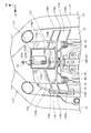
図1は、本発明の実施の形態に係る自動二輪車1の左側面図であり、図2は自動二輪車1の内部構造を左側方から見た図であり、図3は図2を上方から見た図である。
自動二輪車(鞍乗り型車両)1は、シート10に着座した乗員(運転者)RDが足を載せる低床のステップフロア68を有するスクータ型車両であり、車体フレームF(図2)の前方に前輪2を有し、駆動輪である後輪3は、車両後部に配置されるユニットスイングエンジン(ユニットスイングパワーユニットとも言う)Uに軸支されている。車体フレームFは、樹脂製の車体カバーCによって覆われている。
なお、図2では、説明の便宜上、車体カバーCの一部を取り外して示すとともに、スロットルケーブル120と、シートロック解除用の操作ケーブル123とを太線で示している。
Hereinafter, an embodiment of the present invention will be described with reference to the drawings. In the description, descriptions of directions such as front and rear, right and left and up and down are the same as directions with respect to the vehicle body unless otherwise specified. Further, in each figure, the symbol FR indicates the front of the vehicle body, the symbol UP indicates the upper side of the vehicle body, and the symbol LE indicates the left side of the vehicle body.
FIG. 1 is a left side view of a
The motorcycle (saddle-ride type vehicle) 1 is a scooter type vehicle having a low
In FIG. 2, for convenience of explanation, a part of the vehicle body cover C is removed and the
図4は、車体フレームFを示している。
図2〜図4に示すように、車体フレームFは、金属製のチューブやパイプを溶接によって複数連結して形成されており、メインフレーム11は、前部に設けられるヘッドパイプ12と、ヘッドパイプ12から後下方に延出した後、略水平に後方へ延び、後部で後上方に延びる左右一対の下側ダウンフレーム13,13と、下側ダウンフレーム13,13の前下部から後上方へ車両後部まで延出する左右一対のシートレール14,14と、ヘッドパイプ12から下側ダウンフレーム13,13の上方を後下方に延びてシートレール14,14に連結される左右一対の上側ダウンフレーム(以下、アッパーフレームと称する)15,15とを有している。
下側ダウンフレーム13,13は、ヘッドパイプ12に前端が連結されて後下方へ延出する下方延出部70と、下方延出部70の下端から後方に略水平に延出する水平延出部71と、水平延出部71の後端から後上方に延出する斜め上方延出部72とを有している。
FIG. 4 shows the vehicle body frame F.
As shown in FIGS. 2 to 4, the vehicle body frame F is formed by connecting a plurality of metal tubes and pipes by welding, and the
The lower down frames 13, 13 are connected to the
図4に示すように、メインフレーム11には、左右のフレームを連結するクロスメンバとして、下側ダウンフレーム13,13の下方延出部70,70の上部間を連結する前上部クロスメンバ16と、下方延出部70,70の下部間を連結する前クロスメンバ17と、下側ダウンフレーム13,13の水平延出部71,71間を連結する水平部クロスメンバ18と、アッパーフレーム15,15間をつなぐ前後一対のクロスメンバ19と、シートレール14,14間を連結する中間クロスメンバ20と、シートレール14,14の後部間を連結する後部クロスメンバ21とを有している。水平部クロスメンバ18は、水平延出部71,71にボルト止めによって連結されている。
As shown in FIG. 4, the
アッパーフレーム15,15間をつなぐ前後一対のクロスメンバ19は、アッパーフレーム15,15の上部間をつなぐ板状の上部クロスメンバ19A(後述する図7参照)と、下部間をつなぐ円柱断面の下部クロスメンバ19B(図4)とを備えている。
下側ダウンフレーム13,13の斜め上方延出部72,72の上部には、車幅方向外側に延出する左右一対のタンデムステップステー22,22が設けられている。
ヘッドパイプ12の前面には、灯火類や車体カバーCなどを支持する籠状の前部フレーム24が連結されている。
A pair of front and
A pair of left and right tandem step stays 22, 22 extending outward in the vehicle width direction are provided on the upper portions of the diagonally upward extending
On the front surface of the
前輪2を操向する操舵系は、ヘッドパイプ12に回動自在に軸支されるステアリングシャフト9(図2)と、このステアリングシャフト9の上部に連結されるハンドル25とを有している。ステアリングシャフト9の下端は、左右一対のフロントフォーク26,26(図1)に連結されており、前輪2は、フロントフォーク26,26の下端に軸支され、ハンドル25による操作によって操向される。
The steering system that steers the
ユニットスイングエンジンUは、図1に示すように、エンジンEと、ベルト式の無段変速機構が収容された伝動ケースMとが一体化されたユニットスイング式であり、後輪3を支持するスイングアームとしての機能も有している。ユニットスイングエンジンUは、その前部に連結されるリンク部材27を介して、下側ダウンフレーム13,13の後部に連結されており、リンク部材27に設けられるピボット軸28を中心にして上下に揺動自在である。なお、リンク部材27の前端は、左右一対のパワーユニット支持部85,85(図4)を介して下側ダウンフレーム13,13の後部に連結されている。
エンジンEは、水冷式の4サイクル単気筒エンジンであり、シリンダ軸線29(図2)が略水平に前方へ延びるように配置されている。エンジンEは、ユニットスイングエンジンUの前部に配置されるクランクケース30の前面に、シリンダブロック及びシリンダヘッドからなるシリンダ部32(図2)が結合されて構成されている。
As shown in FIG. 1, the unit swing engine U is a unit swing type in which an engine E and a transmission case M in which a belt type continuously variable transmission mechanism is housed are integrated, and a swing that supports the
The engine E is a water-cooled four-cycle single-cylinder engine, and is arranged so that the cylinder axis 29 (FIG. 2) extends forward substantially horizontally. The engine E is configured by connecting a cylinder portion 32 (FIG. 2) including a cylinder block and a cylinder head to the front surface of a
伝動ケースMは、クランクケース30の後部から後輪3の左側方を通って後方に延びており、伝動ケースMの後部に後輪3の車軸3A(図2)が支持されている。そして、エンジンEの出力は、伝動ケースM内の無段変速機構を介して後輪3に伝達される。伝動ケースMの後端及びアーム部33の後端とシートレール14,14との間には、左右一対のリヤサスペンション34,34が掛け渡されている。
伝動ケースMの上面には、外気を吸い込むエアクリーナボックス35(図1、図2)が設けられている。エアクリーナボックス35は、シリンダ部32の吸気ポートに接続された不図示のスロットルボディに不図示のコネクティングチューブを介して接続されている。このスロットルボディは、ハンドル25に設けられたスロットルから伸びるスロットルケーブル120(図2)を介してスロットル開度が調整される。
シリンダ部32の排気ポートに接続された排気管37は、エンジンEの下方を通って後方に延び、アーム部33の外側(右側)に固定されたマフラー38(図3)に接続される。伝動ケースMの後下部には、車両を直立状態に支持可能なメインスタンド39が設けられている。
The transmission case M extends rearward from the rear portion of the
On the upper surface of the transmission case M, an air cleaner box 35 (FIGS. 1 and 2) for sucking outside air is provided. The
The
エンジンE用の燃料を貯留する燃料タンク40は、図2に示すように、側面視において、前面が下側ダウンフレーム13の下方延出部70に沿って後下がりに傾斜するとともに、後面がアッパーフレーム15に沿って後下がりに傾斜する形状に形成されており、上下方向では、ヘッドパイプ12の下部の後方から下側ダウンフレーム13の水平延出部71近傍まで上下に長く延在している。つまり、燃料タンク40は、左右の下側ダウンフレーム13,13及びアッパーフレーム15間を後下がりに傾斜するタンクに形成されている。
燃料タンク40前部の下方に空く空間には、エンジンEの冷却水を冷却する板状のラジエータ41が設けられ、ラジエータ41と燃料タンク40とを前後方向にコンパクトに配置している。また、車体フレームFには、車両を左側に傾斜した状態に支持可能なサイドスタンド47(図1)が取り付けられている。
As shown in FIG. 2, the
A plate-
燃料タンク40の後方には、物品を収納可能な大容量の収納ボックス44(図2、図3)が配設されている。
図5は、収納ボックス44を上方から見た図であり、図6は左側方から見た図である。
収納ボックス44は、幅(車幅方向の長さ)に比して前後方向に長いボックス形状に形成され、シートレール14,14の前後中間部に設けられたボックスステー80,80(図4)と、シートレール14,14の後部とに、複数の締結部材91,92(図3)によって締結されている。このように取り付けられることにより、収納ボックス44は、シートレール14,14間を、燃料タンク40の後部の近傍から伝動ケースMの上方まで、シートレール14,14に沿って後上がりに延在する。
A large-capacity storage box 44 (FIGS. 2 and 3) capable of storing articles is disposed behind the
5 is a view of the
The
図5中、符号93,94は、締結部材91,92が通る左右一対の貫通孔であり、貫通孔93は、収納ボックス44の前後中間部から左右に張り出す左右一対の張り出し部95F,95Fに設けられ、貫通孔94は、収納ボックス44の後部から左右に張り出す左右一対の張り出し部95R,95Rに設けられている。
これら左右の張り出し部95F〜95Rは、収納ボックス44のうち最も車幅方向外側に張り出す部位となっており、これら張り出し部95F〜95Rを車体フレームFへの固定部とすることによって、収納ボックス44を安定して車体フレームFへ支持できるように構成されている。
In FIG. 5,
These left and right projecting
収納ボックス44は、燃料タンク40と下側ダウンフレーム13の斜め上方延出部72との間に配置される前部収納部44Aと、ユニットスイングエンジンUの上方に配置される後部収納部44Bとを有し、これらが樹脂成形によって一体に形成されている。
収納ボックス44の上面は、その全長に亘って開口する開口部44K(図3)を有し、この開口部44K(図3)は、乗員用のシート10(図1)によって開閉自在に塞がれる。シート10は、その前端を支点にして上下に回動自在に車体フレームFに支持され、運転者(図1に示す乗員RD)が着座する前部シート10Aと、前部シート10Aよりも一段高く形成されて同乗者が着座する後部シート10Bとを一体に有している。
収納ボックス44の後方においてシートレール14,14の後部には、グラブレール48(図1)が固定されている。
The
The upper surface of the
A grab rail 48 (FIG. 1) is fixed to the rear of the seat rails 14 and 14 behind the
図1に示すように、車体カバーCは、ヘッドパイプ12の前方及び左右側方を覆うとともに、下方延出部70の前方を下方に延びるフロントカバー50と、フロントカバー50の下部に連結されるフロントロアカバー51と、ハンドル25の下方でフロントカバー50の上部に連結される上部カバー52と、フロントカバー50の左右の縁部に連結されてヘッドパイプ12、アッパーフレーム15,15及び下方延出部70を後方及び側方から覆う上部インナーカバー53と、上部インナーカバー53の下縁に連結され、アッパーフレーム15,15及び下方延出部70を覆う左右一対の下部インナーカバー54,54と、フロントカバー50の下部及び下部インナーカバー54,54の下縁に連結される左右一対のステップカバー55,55と、フロントカバー50の下部及びステップカバー55,55の下部に連結されてステップフレーム23,23を側方から覆う左右一対の前部フロアスカート56,56と、前部フロアスカート56,56に連続して後方へ延び、下側ダウンフレーム13,13を覆う左右一対の後部フロアスカート57,57と、左右の水平延出部71,71を下方から覆うアンダーカバー58と、下部インナーカバー54,54及びステップカバー55,55の後部に連結され、シート10の下方で収納ボックス44及びシートレール14,14を側方から覆う左右一対のボディサイドカバー59,59と、ボディサイドカバー59,59の後部に連結されるテールカバー60とを有している。
As shown in FIG. 1, the vehicle body cover C covers the front and left and right sides of the
左右のステップカバー55,55の底部には、前部シート10Aに着座した乗員RDが足を載せるステップフロア68がそれぞれ形成されている。
上記の上部インナーカバー53、下部インナーカバー54,54及びステップカバー55,55は、ハンドル25、シート10間の下方に配置されるセンタートンネル部250を形成する部品である。
センタートンネル部250は、左右のステップフロア68より高い位置に配置される左右一対のアッパーフレーム15,15及び燃料タンク40を上方から覆うようにシート10下方と、乗員RDの足の前方を覆うレッグシールド601とを連結する。
このセンタートンネル部250では、レッグシールド601に隣接する部分、つまり、上部インナーカバー53、下部インナーカバー54,54からなる足跨ぎ部250Aが後方に行くほど車幅中心側になるように傾斜し、乗員RDの乗降性が向上している。
The upper
The
In the
フロントカバー50の前部には、後上方に延びるウインドスクリーン61が設けられている。フロントカバー50の前端には、ヘッドライト62が設けられ、左右一対のウインカー63は、ヘッドライト62の上部に連続して設けられている。ヘッドライト62とウインドスクリーン61との間には、板状のガーニッシュ64が設けられている。
フロントフォーク26,26には、前輪2を上方から覆うフロントフェンダー65が設けられている。フロントフェンダー65の上方においてフロントロアカバー51の上部とフロントカバー50との間には、前輪2を配置するための開放部187が形成されており、操舵系は、開放部187を貫通して上下に延在する。
ボディサイドカバー59,59の下方には、後輪3を上方から覆うリヤフェンダー66が設けられている。
後部シート10Bの同乗者が足を載せる可倒式の一対のタンデムステップ67は、タンデムステップステー22,22(図4)に支持されている。
上記のフロントカバー50と、上部カバー52と、上部インナーカバー53とによって、ヘッドパイプ12近傍(車両前部)を覆うフロントカウルとなる前部カバー130が構成されている。
A
The
A
A pair of retractable tandem steps 67 on which the passengers of the
The
図3に示すように、ハンドル25中央部後方の領域は、センターパネル138で覆われており、このセンターパネル138には、メインキーによって操作されることで車両のイグニッションスイッチのオン/オフを切り替え可能なキーシリンダー部141と、左右一対の押下式操作子142,143とが設けられている。各操作子142,143には、操作ケーブル(配管)の一端が各々連結され、各操作子142,143の操作に応じて操作ケーブルが牽引され、各操作子142,143を介して物品収納部132の蓋部134のロックを解除し、また、後述するシートロックを解除する。すなわち、これらは車体前方の物品収納部ロック解除装置、及び、シートロック解除装置を構成している。
As shown in FIG. 3, the area behind the center of the
<燃料タンク40のリッド構造>
次に、燃料タンク40のリッド構造について説明する。
図7は、燃料タンク40を周辺構造と共に示す側断面図である。また、図8は、図7のVIII矢視図であり、図9は図8の斜視図である。なお、図8及び図9は、車体カバーCを除いた状態を示している。
図7に示すように、上部インナーカバー53のセンタートンネル部250の領域には、燃料タンク40がその上部に備える給油キャップ40Aを外部に露出させるための開口部53Kが設けられている。この開口部53Kは、蓋体として機能するフューエルリッド(以下、「リッド」と言う)101により開閉される。
図10は、リッド101を閉じた状態を図7とは異なる断面で示した図である。
図7〜図10に示す符号102は、リッド101の主フレームを構成する金属製のリッド本体であり、このリッド本体102に、開口部53Kを閉塞自在なカバーであるリッドカバー103が装着されるようになっている。また、図7及び10中、符号105は、燃料タンク40の給油口の周囲を囲う囲いカバーである。この囲いカバー105は、上方が開口する箱形状に形成され、給油キャップ40Aを含む給油口周囲を囲み、この囲いカバー105の上方開口が、上記開口部53Kに連通するように構成されている。
<Lid structure of
Next, the lid structure of the
FIG. 7 is a side sectional view showing the
As shown in FIG. 7, an
FIG. 10 is a view showing a state in which the
A
図11は、リッド本体102の後部を周辺構成と共に示す斜視図である。なお、図11中、符号96は、燃料タンク40のリッド101よりも後下方に設けられている燃料ポンプを示している。
図7,図8及び図11に示すように、左右一対の下側ダウンフレーム13の下部間をつなぐ下部クロスメンバ19Bには、車幅中央から前上がりに延びる金属製のステー19B1が溶接などで接合されている。このステー19B1には、リッド本体102を開閉自在に支持するリッド用ブラケット107(図7,図8)と、車体カバーCの一部を構成する上部インナーカバー53とが単一の締結部材108によって共締めされている。
前掲図8に示すように、リッド用ブラケット107は、上記ステー19B1から左右に突出してその両側から上方に屈曲した上方に立ち上がる左右一対の支持板部107Aを有し、この左右一対の支持板部107Aに、同軸に並ぶ支持軸109,109を介して、上記リッド本体102から延びる左右一対のリッド用アーム102A,102Aが回動自在に連結されている。つまり、リッド用ブラケット107は、リッド101を開閉自在に支持する開閉機構として機能している。
FIG. 11 is a perspective view showing the rear part of the lid
As shown in FIGS. 7, 8, and 11, a metal stay 19B1 extending upward from the center of the vehicle width is welded to the
As shown in FIG. 8, the
ここで、図12は、リッド本体102を周辺構成と共に裏側から見た図を示している。
この図に示すように、リッド本体102には、複数(本構成では3個)の締結部材106を用いてリッドカバー103が固定されている。
上部インナーカバー53は、車幅中央後端部に下方に突出する下方突出部53Lを有しており、この下方突出部53Lがリッド用ブラケット107の上方に重ねられ、その状態で、上方から単一の締結部材108が下方突出部53Lを通ってリッド用ブラケット107に締結される。これによって、リッド用ブラケット107及び上部インナーカバー53が共締めされる。
このようにして、リッド101が、リッド用ブラケット107を介して、上部インナーカバー53と車体フレームFとに固定されるので、リッド101を、上部インナーカバー53に正確に位置決めでき、組付精度を向上することができる。これにより、リッドカバー103と上部インナーカバー53の開口部53Kとの間の隙間を最小にして精度良く組み付けることができる。
また、共締めによりリッド101と上部インナーカバー53とを車体フレームFに固定するので、別々に固定する場合よりも部品点数を削減でき、生産性向上、軽量化及び省スペース化を図ることができる。
Here, FIG. 12 shows a view of the
As shown in this figure, a
The upper
In this way, the
Further, since the
また、リッド101は、リッド用ブラケット107に支持された付勢部材101F(図7,図8)によって開側に付勢されるとともに、このリッド101を閉状態にロック可能なリッドロック機構110(図8など)によって閉状態に保持できるように構成されている。
このため、リッドロック機構110によってロックを解除することによって、リッド101が自動的に開き、乗員RDがリッド101を直接開く操作を不要にしている。
The
For this reason, by releasing the lock by the
次いで、リッドロック機構110について詳述する。
図13は、図8のリッドロック機構110周辺部分の拡大図であり、図14は、リッドロック機構110を後方から見た断面図である。
図13及び図14に示すように、リッドロック機構110は、リッド本体102に向けて移動する単一のロックロッド111を有し、このロックロッド111をリッド本体102に係止させてリッド101の開動作を禁止する機構であり、このロックロッド111は、リッド101の前上方に配設されるロック部材112に支持されている。
Next, the
13 is an enlarged view of the periphery of the
As shown in FIG. 13 and FIG. 14, the
ロック部材112は、樹脂材を一体成形して形成された樹脂部品であり、ロックロッド111を支持するロッド支持部115と、ロッド支持部115から左右に拡がり、左右一対のアッパーフレーム15,15上に載置される左右一対の足部116,116とを一体に備えている。各足部116,116の基端部には、左右一対の締結部材97,97(図8,図10)によって上部インナーカバー53を締結するための締結部98,98が設けられている。
ロッド支持部115は、略平板状の基材の両側に車体前後方向に延びる左右一対の縦壁115A,115Aを有し、この縦壁115A,115Aの間に、前後に間隔を空けて車幅方向に沿って延びる複数(本構成では3個)の隔壁(以下、横壁という)115Bを一体に有している。そして、前後一対の横壁115Bをロックロッド111が貫通することで、ロックロッド111が軸方向に移動自在に支持される。つまり、ロッド支持部115は、ロックロッド111のガイド部材として機能している。
このロッド支持部115の各壁115A,116Bは補強リブとしても機能するので、ロッド支持部115を、軽量かつ十分に剛性を備えた部品に形成することができる。
The
The
Since the
この自動二輪車1において、ロックロッド111は、センタートンネル部250内の車幅方向中央の位置に設けられ(図14)、センタートンネル部250の傾斜に沿って後下がりに配置される(図7)。このため、センタートンネル部250内部の上方スペースを有効利用して配設することができる。
この場合、ロックロッド111は、ロッド支持部115により、その軸線方向に直線的に移動自在にガイドされ、図7に示すように、ロックロッド111の先端(後端)が、リッド本体102の前端(前上端)に開口する開口部に入ることによって、リッド本体102の開側への移動をロックロッド111によって規制することができる。
なお、ロックロッド111は、不図示の付勢部材によりリッド本体側(ロック側)に付勢され、リッド101を閉じた状態に保持できるように構成されている。
In the
In this case, the
The
図7に示すように、ロックロッド111の前上端に位置する基端部には、乗員RDが操作する所定の操作子(本構成では操作子143(図3))の操作に応じて牽引される操作ケーブル(配管)121の一端が連結されている。
この操作ケーブル121は、外筒を構成するアウターケーブル121Aの内部をインナーケーブル(摺動物)121Bが摺動するワイヤーケーブル構造を有し、アウターケーブル121Aの先端が、ロッド支持部115の前壁を構成する最前端の横壁115Bに固定され、インナーケーブル121Bの先端がロックロッド111に固定される。このため、乗員RDの所定操作によりインナーケーブル121Bが牽引されると、ロックロッド111が前上方に引き出され、燃料タンク40のリッド101のロックを解除することができる。
As shown in FIG. 7, the proximal end portion located at the front upper end of the
This
本構成では、図7及び図12に示すように、操作ケーブル121がロックロッド111近傍でロックロッド111の延長軸線上に直線的に配置されるので、ロックロッド111が円滑に作動し、その作動感を向上させることができる。
また、図9に示すように、ロッド支持部115には、上方を覆う蓋材115Fが締結部材99によって一体に固定されている。この蓋材115Fには、リッドロック用のケーブル以外のケーブルであるシートロック解除用のケーブル123をガイドする第1のケーブルガイド部115Gが一体に設けられている。
また、図7に示すように、ロッド支持部115の前下部には、下方に延びてアッパーフレーム15,15間の上部クロスメンバ19Aに係止する爪部(係止部)115Hが一体に設けられている。
In this configuration, as shown in FIGS. 7 and 12, since the
Further, as shown in FIG. 9, a
Further, as shown in FIG. 7, a claw portion (locking portion) 115H that extends downward and locks to the
図8に示すように、左右一対の足部116,116は、給油口(給油キャップ40A)の周囲を囲うカバー105の上縁に沿って左右に延びるとともに、図9に示すように、左右のアッパーフレーム15,15間を左右に跨ぐ形状に形成されている。この足部116,116は、図9及び図12に示すように、下方に突出する複数(前後方向に3個)の横壁116Aを有し、これら横壁116Aの下面が、アッパーフレーム15,15の外周面に沿って湾曲する湾曲形状に形成されている。
このため、各足部116,116の横壁116Aをアッパーフレーム15,15上に載置することによって、ロック部材112を車幅方向に位置決めすることができる。この場合、車幅中心とロック部材112の車幅中心とが一致し、ロックロッド111を、リッド101をロック可能な位置に容易に位置決めすることができる。
この足部116,116においても、ロッド支持部115と同様に、横壁116Aや左右一対の縦壁115A,115Aが補強リブとしても機能するので、軽量かつ十分に剛性を備えた部品に形成することができる。
As shown in FIG. 8, the pair of left and
For this reason, the
Similarly to the
上述したように、このロック部材112は、その前上端から下方に延びて、アッパーフレーム15,15間の上部クロスメンバ19Aに係止する爪部115H(図7)を有しているので、この爪部115Hを上部クロスメンバ19Aに係止させて、ロック部材112を車体フレームF側に仮係止させることができる。
この仮係止時は、図7及び図9に示すように、ロック部材112の足部116,116を、アッパーフレーム15,15に載置し、かつ、爪部115Hが上部クロスメンバ19Aに係止した状態であり、これによって、ロック部材112を取り付け予定位置に正確かつ容易に位置決めすることができる。
その後、ロック部材112の上方に上部インナーカバー53を被せ、図9に示すように、このカバー53の上方から締結部材97,97を、ロック部材112に設けられた締結部98,98に締結することによって、上部インナーカバー53とロック部材112とを締結する(図10参照)。これによって、ロック部材112の取り付けが完了する。
As described above, the
At the time of this temporary locking, as shown in FIGS. 7 and 9, the
Thereafter, the upper
この場合、ロック部材112の荷重を、車体フレームFである左右一対のアッパーフレーム15,15で支持しながら、ロック部材112を上部インナーカバー53に固定することができる。従って、ロック部材112と上部インナーカバー53との組み付け精度を向上しながら、車体カバーCである上部インナーカバー53にロック部材112を支持するほどの強度が不要となり、上部インナーカバー53の軽量化を図ることができる。
In this case, the
また、本構成では、ロック部材112が、リッド101が固定される上部インナーカバー53に固定されるので、ロック部材112とリッド101の組み付け誤差を抑えることができ、これによっても、ロック部材112の作動性を良好に保つことができる。
さらに、このロック部材112においては、図7に示すように、ロック部材112の左右一対の縦壁115A,115Aが、側断面視で、上部インナーカバー53の屈曲部53Nに略沿って屈曲する屈曲部115N,115N(図7、図9)を備えており、この屈曲部115N,115Nが、ロック部材112を組んだ場合に上部インナーカバー53の屈曲部53Nに当接する当接部として機能する。このため、この当接により、ロック部材112を、上部インナーカバー53とアッパーフレーム15,15との間に挟持することができる。
Further, in this configuration, since the
Further, in the
この当接位置は、ロック部材112が、上部インナーカバー53に固定される部位(締結部材97,97と締結部98,98)から離れた位置に相当するので、この固定部位と上記挟持部位とによって、ロック部材112を間隔を空けて複数箇所で固定することができ、ロック部材112の支持力を効率よく向上させることができる。
このため、上部インナーカバー53の剛性を低減しても、ロック部材112を介して上部インナーカバー53をフレーム支持することができ、上部インナーカバー53の支持強度を確保し易くなる。これにより、ロック部材112の支持強度を確保しつつ上部インナーカバー53の薄型化などによる軽量化を図ることもできる。
This contact position corresponds to a position where the
For this reason, even if the rigidity of the upper
また、ロック部材112は、左右一対のアッパーフレーム15,15間のスペース、及び、アッパーフレーム15,15と上部インナーカバー53との間のスペースを利用して車幅中央に配置されるので、自動二輪車1のデッドスペースを有効利用して配置することができる。
さらに、図9に示すように、左右の足部116,116のうち一方(本構成では車体左側の足部116)には、シートロック解除用のケーブル123をガイドする第2のケーブルガイド部116Gが一体に形成されている。このケーブルガイド部116Gは、上方に開放する樋形状を有し、一方(左側)のアッパーフレーム15に沿わせてケーブル123を支持する。
つまり、シートロック解除用のケーブル123は、ロック部材112の前上部に設けられた第1のケーブルガイド部115Gにガイドされた後に、第2のケーブルガイド部116Gにガイドされる。ケーブル123は、後段に詳述するが、左側のアッパーフレーム15及び収納ボックス44の左側縁に沿って後方に向けて配索され、収納ボックス44後端に相当する位置に設けられたシートロック解除用のシートロック装置372(後述する図15参照)に連結される。
このように、リッド101をロックするロック部材112を、リッドロック用のケーブル121以外のケーブルであるシートロック解除用のケーブル123をガイドするガイド部材に兼用するので、部品点数の削減が可能である。
Further, since the
Further, as shown in FIG. 9, a second
That is, the seat
Thus, since the
以上説明したように、本実施の形態によれば、リッド101を閉状態にロック可能なロック部材112が、車体カバーCの一部を構成する上部インナーカバー53に固定されるとともに、上部インナーカバー53下方の車体フレームFであるアッパーフレーム15,15に載置されるので、車体カバーC側にロック部材112を取り付けて車体カバーCとロック部材112との位置精度を確保するとともに、ロック部材112の荷重を車体フレームFで支えることができ、その分、車体カバーCにおけるロック部材112の取り付け剛性を抑制することができる。
従って、車体カバーCとロック部材112との位置精度を確保しながら、車体カバーCの軽量化を図ることができる。
As described above, according to the present embodiment, the
Accordingly, it is possible to reduce the weight of the vehicle body cover C while ensuring the positional accuracy between the vehicle body cover C and the
また、リッド101を開閉自在に支持する開閉機構を構成するリッド用ブラケット107が、車体カバーCである上部インナーカバー53と車体フレームFであるアッパーフレーム15,15とに共締めされるので、上部インナーカバー53、ロック部材112及びリッド101の位置精度を向上させることができ、組み付け時の管理工数を低減して品質を向上させることができる。
また、ロック部材112は、アッパーフレーム15,15に載置された後に上部インナーカバー53に固定されるので、ロック部材112を予め車体フレームF(アッパーフレーム15,15)に組み付けた状態で、上部インナーカバー53を組み付けることができ、生産性が向上する。
Further, since the
Further, since the
また、車体フレームFの一部を構成する左右一対のアッパーフレーム15,15にロック部材112が跨るように載置されるので、ロック部材112の荷重を良好に受けることができるとともに、ロック部材112の車幅方向の位置決めも容易となる。これにより、ロック部材112と車体フレームFとの組み付け時の位置合わせが良好となり、これによっても生産性が向上する。
さらに、アッパーフレーム15,15が車体前後方向に傾斜し、傾斜上方側に上部クロスメンバ19Aを備え、ロック部材112は、上部クロスメンバ19Aに上方から係止する係止部となる爪部115Hを有するので、車体フレームFの傾斜と上部クロスメンバ19Aを利用してロック部材112の前後方向の位置決めを仮組することができ、これによっても生産性が向上する。
Further, since the
Further, the
また、ロック部材112に、リッドロック用以外のケーブル(本構成ではシートロック解除用のケーブル)123をガイドするガイド部として機能する第1及び第2のケーブルガイド部115G,116Gを設けたので、ロック部材112を車体フレームFに載置した状態で他のケーブル123を組み付けることができ、これによっても生産性が向上する。また、他のケーブル123のための専用ガイド部品や、この種のガイド部品の車体フレームFへの溶接を低減できるので、コスト低減及び軽量化を図ることができる。
また、ロック部材112は、上部インナーカバー53(車体カバーC)に固定される部位と異なる部位に、上部インナーカバー53が上方から当接する当接部となる屈曲部115N,115Nを有するので、ロック部材112を上部インナーカバー53とアッパーフレーム15,15(車体フレームF)との間に挟持することができ、車体カバーCの剛性を低減してもロック部材112を介して車体カバーCの支持強度を確保し易くなる。従って、車体カバーCの支持強度と車体カバーCの軽量化とを両立することができる。
In addition, since the
Further, since the
<車体後部の構造及びシートロック解除用ケーブル123の配索構造>
次に、車体後部の構造を説明する。
図15は、収納ボックス44を周辺構成と共に示す側断面図である。
収納ボックス44の前部収納部44Aは、シートレール14,14の前後中間位置を連結する中間クロスメンバ20(図4)よりも前方で下方に膨出し、単一のヘルメットHL1を収容可能なヘルメット収納部を形成している。この前部収納部44Aの下方には、各部への電力供給源となるバッテリー651が配置されており、前部収納部44Aの底板のカバー652を外すことによって、バッテリー651のメンテナンス作業や取替えを容易に行うことが可能である。
また、収納ボックス44の後部収納部44Bは、中間クロスメンバ20(図4)の後方で下方に膨出し、単一のヘルメットHL2を収容可能なヘルメット収納部を形成するとともに、このヘルメット収納部の後方にてヘルメット収納部の床との間に段差を介して後方に延在する上げ底部655を有している。
<The structure of the rear part of the vehicle body and the wiring structure of the
Next, the structure of the rear part of the vehicle body will be described.
FIG. 15 is a side sectional view showing the
The
The
この上げ底部655の前壁を形成する壁部656は、上面視で後方凸に湾曲する壁に形成されており、つまり、後部収納部44BにヘルメットHL2が収納された場合に、そのヘルメットHL2の外縁に沿う形状に形成されている。
上げ底部655は、壁部656の上縁から後部収納部44Bの幅全体に渡って後方へ水平に延在し、その後縁が上方に立ち上がり、後部収納部44Bのヘルメット収納部の後方に、サブ収納ボックス671を形成する。このサブ収納ボックス671とヘルメット収納部との間には、車幅方向に延在する仕切り板662が着脱自在に設けられる。
The
The raised
図16は、収納ボックス44後部を周辺構成と共に示す斜視図である。
グラブレール48は、後部シート10Bの後縁に沿って延びる前方に開放するU字状に形成され、後部シート10Bに着座した同乗者が把持する把持部材として機能するものであり、前方に延出する左右一対の腕部48A,48Aと、腕部48A,48A同士を連結する連結部48Bとを有している。なお、図16は、左右一対のボディサイドカバー59,59を外した状態を示している。
図15及び図16に示すように、左右一対の腕部48A,48A間の左右中央部には、シート10をロックするシートロック装置372のシートキャッチプレート373が取り付けられている。
シートロック装置372は、シートキャッチ機構とも称する機構であり、シート10が閉じた場合に、シート10の後端下部に設けられたシートキャッチに係合することによりシート10を閉じた状態にロックする。
このシートロック装置372には、車体前部に設けられたシートロック解除装置(操作子143など)の操作に応じて牽引されるシートロック解除用の操作ケーブル123の先端が接続され、この操作ケーブル123の作動によってシート10のロックを解除することができる。
この操作ケーブル123についても、リッドロック解除用の操作ケーブル121と同様に、外筒を構成するアウターケーブル123Aの内部を不図示のインナーケーブル(摺動物)が摺動するケーブル構造となっている。
FIG. 16 is a perspective view showing the rear portion of the
The
As shown in FIGS. 15 and 16, a
The
The
Similarly to the
続いて、上記操作ケーブル123の配索構造について説明する。
この操作ケーブル123は、車体前部のセンターパネル138に設けられた操作子143の位置から、まず、ロック部材112に設けられた第1のケーブルガイド部115G(図9)にガイドされることによって、左側のアッパーフレーム15に向けて配置され、同ロック部材112に設けられた第2のケーブルガイド部116G(図9)でガイドされることによって、図2に示すように、左側のアッパーフレーム15の上面をこのフレーム15に沿って後下がりに傾斜するように配置される。
この場合、操作ケーブル123を、上方から第1及び第2のケーブルガイド部115G,116Gに取り付けるので、取り付け作業が容易である。
Next, the wiring structure of the
The
In this case, since the
その後、操作ケーブル123は、収納ボックス44の開口部44Kの周縁外側に形成された第3及び第4のケーブルガイド部151,161(図2,図3)にガイドされることによって、同図2に示すように、側面視で、左側のアッパーフレーム15と収納ボックス44の前端とが近接する位置を谷部として後ろ上がりに配置され、収納ボックス44の後方に位置するシートロック装置372(図15)まで配索される。なお、この配索作業は、左側のボディサイドカバー59だけを外した状態で行うことが可能である。
ここで、図17中、符号145は、左側のアッパーフレーム15に設けられ、操作ケーブル123を支持するクランプである。このクランプ145は、ロック部材112に設けられた第2のケーブルガイド部116Gと、収納ボックス44に設けられた第3のケーブルガイド部151との間で操作ケーブル123を支持する。このように本構成では、アッパーフレーム15に設けられるケーブル支持部材が単一のクランプ145だけであり、アッパーフレーム15以外の部品(ロック部材112、収納ボックス44)を利用して操作ケーブル123を複数箇所で支持する構成としている。
Thereafter, the
Here, in FIG. 17,
図17は、第3のケーブルガイド部151を周辺構成と共に示す斜視図であり、図18は、第3のケーブルガイド部151の断面を周辺構成と共に示す図である。
図5,図6及び図17に示すように、第3のケーブルガイド部151は、収納ボックス44の前部の車幅方向一方側(左側)に独立して一体に設けられている。また、図18に示すように、第3のケーブルガイド部151は、収納ボックス44の上縁よりも低い位置に設けられ、第4のケーブルガイド部161の前方であって、第4のケーブルガイド部161よりも低い位置に設けられている。
同図18に示すように、第3のケーブルガイド部151は、下方に開口する凹形状(コの字状)に形成されており、操作ケーブル123の上限位置及び左右位置を規制する。これにより、第3のケーブルガイド部151は、図2及び図17に示すように、操作ケーブル123を、後下がりのアッパーフレーム15と第4のケーブルガイド部161との間で下方凸に屈曲させた状態にガイドする屈曲ガイド部として機能する。
この第3のケーブルガイド部151により、操作ケーブル123を後下がりのアッパーフレーム15に沿わせた後に、緩やかに屈曲させて、相対的に高い位置にある第4のケーブルガイド部161に向けて大きな曲がり無く配索することができる。
FIG. 17 is a perspective view showing the third
As shown in FIGS. 5, 6, and 17, the third
As shown in FIG. 18, the third
The third
図17及び図6に示すように、第4のケーブルガイド部161は、収納ボックス44の左側壁の上縁近傍にて該上縁に沿って車幅方向外側に張り出すとともに、その上縁に沿って車体前後方向に渡って延在する樋形状(溝形状)に形成されている。
この第4のケーブルガイド部161については、前部収納部44Aの外周縁に沿って後方へ延びる前部ケーブルガイド部162(図5)と、前部収納部44Aと後部収納部44Bの間の外縁に沿って後方へ延びる中間部ケーブルガイド部163(図5)と、後部収納部44Bの外周縁に沿って後方へ延びる後部ケーブルガイド部164(図5)とに分けて説明する。
As shown in FIGS. 17 and 6, the fourth
As for the fourth
ここで、収納ボックス44の前部収納部44Aは、図5及び図17に示すように、収納ボックス44のうち最も幅狭の部分であって、当該収納部44Aに前向きに収納される単一のヘルメットHL1(図15)の外周に沿って緩やかに湾曲する外縁形状に形成されている。このため、前部ケーブルガイド部162は、平面視で、前部収納部44Aの外縁に沿って緩やかに湾曲するガイドに形成される。
より具体的には、図3に示すように、前部ケーブルガイド部162は、平面視で、前部収納部44Aにおけるアッパーフレーム15と上面視で重なる部分から前部収納部44Aの左側外縁に沿って後方へ延びる樋形状に形成され、同図3に示すように、後方に行くに従って緩やかに車幅方向内側へ延びるように形成されている。
Here, the
More specifically, as shown in FIG. 3, the front
図19は、前部ケーブルガイド部162の縦断面(図17のXIX−XIX断面に相当)を周辺構成と共に示している。図19に示すように、前部ケーブルガイド部162は、上方に開放する凹形状(コの字状)に形成されている。また、図19及び図5に示すように、前部ケーブルガイド部162には、その長手方向に間隔を空けて、前部ケーブルガイド部162内の操作ケーブル123を上方から押さえる押さえ部165を備えている。
この押さえ部165は、前部ケーブルガイド部162内に上方から操作ケーブル123を挿入自在な隙間165A(図19)を空けて前部ケーブルガイド部162に一体に設けられており、同図19に示すように、前部ケーブルガイド部162内で車幅方向外側寄りに配置される操作ケーブル123を上方から抑えることができる。
FIG. 19 shows a vertical cross section (corresponding to the XIX-XIX cross section of FIG. 17) of the front
The holding
上述したように、前部収納部44Aと後部収納部44Bの間には、シートレール14,14に設けられたボックスステー80,80に固定するために車幅方向外側に張り出す左右一対の張り出し部95F,95F(図5)が形成されており、図5に示すように、中間部ケーブルガイド部163は、左側の張り出し部95Fの周縁外側に沿うように形成されている。
より具体的には、中間部ケーブルガイド部163は、同図5に示すように、平面視で、左側の張り出し部95Fの前部にて車幅方向外側に凸に湾曲する凸部163Aと、張り出し部95Fの後部にて車幅方向内側に凹む凹部163Bとを形成するように延在し、つまり、平面視で緩やかなS字カーブを描くように延在しし、このカーブに沿わせて操作ケーブル123を保持する。
As described above, a pair of left and right overhangs projecting outward in the vehicle width direction to be fixed to the box stays 80 and 80 provided on the seat rails 14 and 14 between the
More specifically, as shown in FIG. 5, the intermediate
ここで、図20は、中間部ケーブルガイド部163の縦断面を周辺構成と共に示している。
この図に示すように、中間部ケーブルガイド部163についても、前部ケーブルガイド部162と同様に、上方に開放する凹形状(コの字状)で車体前後方向に延在するとともに、その長手方向に間隔を空けて、操作ケーブル123を上方から押さえる押さえ部165(図5)を備えている。
上記したように、中間部ケーブルガイド部163では、S字カーブに沿わせて操作ケーブル123を保持するので、操作ケーブル123が長手方向にずれにくくなる。しかも、車幅方向内側に湾曲する部分(例えば、凹部163B)では、操作ケーブル123が車幅方向外側寄りに配置されやすいので、この部分に設けられた押さえ部165によって上方から操作ケーブル123を抑え、これによっても操作ケーブル123をずれにくくすることができる。
Here, FIG. 20 shows a longitudinal section of the intermediate
As shown in this figure, the middle
As described above, since the
後部収納部44Bは、図5に示すように、当該収納部44Bに横向きに入る単一のヘルメットHL2(図15)の外周に沿って緩やかに湾曲する外縁形状に形成されているため、前部収納部44Aよりも幅広に形成されている。
同図5に示すように、後部ケーブルガイド部164は、後部収納部44Bの左側外縁に沿って形成されるので、平面視で、張り出し部95Fの後方から車幅方向外側に緩やかに凸に湾曲する凸部164Aを形成しながら後方へ延び、後部収納部44Bの左側隅部164Bまで延在する。
この後部ケーブルガイド部164についても、前部ケーブルガイド部162及び中間部ケーブルガイド部163と同様に、上方に開放する凹形状(コの字状)で車体前後方向に延在するとともに、その長手方向に間隔を空けて、操作ケーブル123を上方から押さえる押さえ部165を備えている。
As shown in FIG. 5, the
As shown in FIG. 5, the rear
The rear
このようにして、シートロック解除用の操作ケーブル123が収納ボックス44側方を緩やかに湾曲するように配索される。湾曲して配索した場合、操作ケーブル123内のインナーケーブル123Bを牽引しても、アウターケーブル123Aがずれ難いので、シートロック装置372を適切に作動させることができる。
また、本構成においては、側面視では(図2)、操作ケーブル123を収納ボックス44の上縁に沿って後ろ上がりに配索することになるが、上記のように操作ケーブル123を平面視で湾曲させて配索し、かつ、押さえ部165により上方から押さえているので、操作ケーブル123を後ろ上がりに配索してもアウターケーブル123Aがずれ難く、シートロック装置372を適切に作動させることが可能である。
In this way, the
In this configuration, in the side view (FIG. 2), the
ところで、左側のボディサイドカバー59は、図20に示すように、収納ボックス44の上部外縁を上方から覆うように装着され、上記前部ケーブルガイド部162,中間部ケーブルガイド部163及び後部ケーブルガイド部164からなる第4のケーブルガイド部161についても上方から覆うように装着される。
ここで、ボディサイドカバー59,59は、車体フレームF(シートレール14)に不図示の締結部材で装着される他に、収納ボックス44の開口部44K周縁に設けた締結穴である締結部166,166(図5)にも、締結部材167,167によって締結されるように構成されている。
より具体的には、締結部166,166は、収納ボックス44の左右一対の張り出し部95F,95Fの近傍に設けられ、この位置は、収納ボックス44の前後略中央位置に設けられ、ボディサイドカバー59,59を効率よく収納ボックス44に位置決め固定することができる。
Incidentally, as shown in FIG. 20, the left body side cover 59 is mounted so as to cover the upper outer edge of the
Here, the body side covers 59, 59 are attached to the vehicle body frame F (seat rail 14) with fastening members (not shown), and are fastening
More specifically, the
このため、左側のボディサイドカバー59を装着した状態では、操作ケーブル123、及び、第4のケーブルガイド部161が覆われ、これらが外観視されない。従って、意図せぬ第三者の操作ケーブル123へのアクセスを困難にして、いたずらなどを抑制でき、また、外部の雨や砂塵などから操作ケーブル123を保護することができる。また、ボディサイドカバー59と収納ボックス44との間に形成される空間を利用して、操作ケーブル123、及び、第4のケーブルガイド部161を配置するので、上記空間の有効利用も可能になる。
For this reason, in a state where the left body side cover 59 is attached, the
このように、本実施の形態によれば、収納ボックス44に一体に形成されるとともにワイヤーケーブル構造の操作ケーブル123をガイドするケーブルガイド部161を備え、このケーブルガイド部161が、収納ボックス44の開口部44Kの周縁外側に沿う樋形状に形成されるので、収納ボックス44の開口部44K周縁を利用して長いガイド部を形成することができ、操作ケーブル123の遊びを抑制しながら部品点数の増加を抑制することができる。また、このケーブルガイド部161によって開口部44K周縁の剛性を高めることもできる。
また、上記操作ケーブル123は、収納ボックス44前方のシートロック解除装置(操作子143など)と、収納ボックス44後方のシートロック装置372との間の動力伝達を行うシートロック解除用のケーブルであるため、収納ボックス44の開口部44K周縁にケーブルガイド部163,164を設けることによって、ケーブル長を最短化することができるとともに、ロック解除の操作性が向上する。
As described above, according to the present embodiment, the
The
また、上記のケーブルガイド部161は、車体カバーCを構成するボディサイドカバー59と収納ボックス44で形成される空間内に配置されるので、操作ケーブル123の露出を抑制することができ、操作ケーブル123へのアクセスを困難にして、いたずらなどの抑制を行うことができる。
また、収納ボックス44の開口部44Kの周縁は、平面視で凸部163A,164Aまたは凹部163Bを形成する湾曲部(前部収納部44A、張り出し部95F及び後部収納部44B)を備えるので、操作ケーブル123を湾曲させてガイドでき、操作ケーブル123の長手方向の位置決めを行うために特別な固定部材を不要にできる。これによって、簡易な構成で操作ケーブル123の遊びを低減することができる。
Further, since the
Further, the peripheral edge of the
また、ケーブルガイド部161は、上方に開放するコの字状(凹状)に形成されるとともに、コの字の開放側端部に車体カバーC(ボディサイドカバー59)が配置されるので、図20に示したように、操作ケーブル123の周囲をケーブルガイド部161と車体カバーCで囲むことができ、操作ケーブル123のガイド効果を高めるとともに操作ケーブル123の保護も行うことができる。
さらに、操作ケーブル123が、ダウンフレームを構成するアッパーフレーム15上部からシートレール14後部側まで配索され、側面視で収納ボックス44がアッパーフレーム15と重なる位置まで延出するとともに、ケーブルガイド部161の前方に、操作ケーブル123を屈曲させた状態にガイドする第3のケーブルガイド部(屈曲ガイド部)151を、収納ボックス44に一体に形成しているので、車体フレームF側のケーブルガイドを可及的に低減して部品点数を低減することができる。
また、車体カバーCと収納ボックス44の開口部44K周縁に、車体カバーCが固定される固定部として機能する締結部166,166を設けているので、操作ケーブル123へのアクセスをさらに困難にすることができる。
Further, the
Further, the
In addition, since fastening
上述した実施形態は、あくまでも本発明の一態様を示すものであり、本発明の主旨を逸脱しない範囲で任意に変形及び応用が可能である。
例えば、上述の実施形態では、フューエルリッド101をロックするロック部材112を、上部インナーカバー53に固定するとともに、アッパーフレーム15,15に載置する場合を説明したが、上部インナーカバー53以外の車体カバーCに固定し、かつ、アッパーフレーム15,15以外の車体フレームFに載置するようにしても良い。また、フューエルリッド101をロックするロック部材112に限らず、車体カバーCに設けられる開口部を開閉自在に覆うリッドをロック可能にするロック部材を、車体カバーCに固定するとともに、車体カバーC下方の車体フレームFに載置するようにしても良い。
また、上述の実施形態では、収納ボックス44に、シートロック解除用の操作ケーブル123をガイドするケーブルガイド部151,161を設ける場合を説明したが、シートロック解除用の操作ケーブル123以外の操作ケーブルなどの様々な配管をガイドするガイド部を設けるようにしても良い。
また、本発明の上記構成は、自動二輪車1に適用する場合に限らず、自動二輪車以外も含む鞍乗り型車両に適用可能である。なお、鞍乗り型車両とは、車体に跨って乗車する車両全般を含み、自動二輪車(原動機付き自転車も含む)のみならず、ATV(不整地走行車両)に分類される三輪車両や四輪車両を含む車両である。
The above-described embodiment is merely an aspect of the present invention, and can be arbitrarily modified and applied without departing from the gist of the present invention.
For example, in the above-described embodiment, the case where the
In the above-described embodiment, the case where the
Further, the above-described configuration of the present invention is not limited to being applied to the
1 自動二輪車(鞍乗り型車両)
2 前輪
3 後輪
10 シート
12 ヘッドパイプ
13 下側ダウンフレーム
14 シートレール
15 アッパーフレーム(上側ダウンフレーム)
44 収納ボックス
44A 前部収納部(湾曲部)
44B 後部収納部(湾曲部)
44K,53K 開口部
53 上部インナーカバー(車体カバー)
59 ボディサイドカバー(車体カバー)
95F 張り出し部(湾曲部)
101 フューエルリッド
107 リッド用ブラケット(開閉機構)
112 ロック部材
115H 爪部(係止部)
115G,116G ケーブルガイド部
115N 屈曲部(当接部)
121A アウターケーブル(外筒)
121B インナーケーブル(摺動物)
123 操作ケーブル
143 操作子(シートロック解除装置)
151 第3のケーブルガイド部(屈曲ガイド部)
161 第4のケーブルガイド部
163A,164A 凸部
163B 凹部
166,166 締結部(固定部)
372 シートロック装置
1 Motorcycle (saddle-ride type vehicle)
2
44
44B Rear storage part (curved part)
44K,
59 Body side cover (body cover)
95F Overhanging part (curved part)
101
112
115G, 116G
121A Outer cable (outer cylinder)
121B Inner cable (sliding object)
123
151 Third cable guide (bending guide)
161 Fourth
372 Seat lock device
Claims (5)
前記車体カバー(53)の下方にフレーム(15)を有し、
前記ロック部材(112)は、前記車体カバー(53)に固定されるとともに、前記フレーム(15)に載置され、
前記リッド(101)を開閉自在に支持する開閉機構(107)を有し、
前記開閉機構(107)は、前記車体カバー(53)と前記フレーム(15)とに共締めされることを特徴とする鞍乗り型車両のリッドロック構造。 An opening (53K) provided in a part of the vehicle body cover (53), a lid (101) provided so as to open and close the opening (53K), and a lock capable of locking the lid (101) in a closed state In the lid lock structure of the saddle-ride type vehicle having the member (112),
The vehicle body cover (53) has a frame (15) below,
The lock member (112) is fixed to the vehicle body cover (53) and placed on the frame (15) ,
An open / close mechanism (107) that supports the lid (101) to be freely opened and closed;
The opening and closing mechanism (107), the lid lock structure for a saddle type vehicle, wherein Rukoto is fastened to said body cover (53) and the frame (15).
Priority Applications (4)
| Application Number | Priority Date | Filing Date | Title |
|---|---|---|---|
| JP2012187256A JP5938302B2 (en) | 2012-08-28 | 2012-08-28 | Lid lock structure for saddle-ride type vehicles |
| US13/935,056 US9440684B2 (en) | 2012-08-28 | 2013-07-03 | Lid lock structure for saddle type vehicle |
| EP13181314.9A EP2703273B1 (en) | 2012-08-28 | 2013-08-22 | Lid lock structure for saddle type vehicle |
| ES13181314.9T ES2684511T3 (en) | 2012-08-28 | 2013-08-22 | Cover locking structure for astride type vehicles |
Applications Claiming Priority (1)
| Application Number | Priority Date | Filing Date | Title |
|---|---|---|---|
| JP2012187256A JP5938302B2 (en) | 2012-08-28 | 2012-08-28 | Lid lock structure for saddle-ride type vehicles |
Publications (2)
| Publication Number | Publication Date |
|---|---|
| JP2014043190A JP2014043190A (en) | 2014-03-13 |
| JP5938302B2 true JP5938302B2 (en) | 2016-06-22 |
Family
ID=49003711
Family Applications (1)
| Application Number | Title | Priority Date | Filing Date |
|---|---|---|---|
| JP2012187256A Expired - Fee Related JP5938302B2 (en) | 2012-08-28 | 2012-08-28 | Lid lock structure for saddle-ride type vehicles |
Country Status (4)
| Country | Link |
|---|---|
| US (1) | US9440684B2 (en) |
| EP (1) | EP2703273B1 (en) |
| JP (1) | JP5938302B2 (en) |
| ES (1) | ES2684511T3 (en) |
Families Citing this family (7)
| Publication number | Priority date | Publication date | Assignee | Title |
|---|---|---|---|---|
| JP5913030B2 (en) * | 2012-03-22 | 2016-04-27 | 本田技研工業株式会社 | Storage structure for saddle-ride type vehicles |
| US9932080B2 (en) * | 2013-12-02 | 2018-04-03 | Kawasaki Jukogyo Kabushiki Kaisha | Straddle-type vehicle |
| JP6547194B2 (en) * | 2017-03-29 | 2019-07-24 | 本田技研工業株式会社 | Swing lock operation part structure of saddle-ride type vehicle |
| EP3647169B1 (en) * | 2017-06-29 | 2021-07-14 | Honda Motor Co., Ltd. | Motorcycle |
| JP6837399B2 (en) * | 2017-08-07 | 2021-03-03 | 株式会社ニフコ | Lid device |
| JP2020059423A (en) * | 2018-10-11 | 2020-04-16 | ヤマハ発動機株式会社 | Saddle-riding type vehicle |
| JP2024085455A (en) * | 2022-12-15 | 2024-06-27 | スズキ株式会社 | Saddle-riding type vehicle |
Family Cites Families (10)
| Publication number | Priority date | Publication date | Assignee | Title |
|---|---|---|---|---|
| JP2867534B2 (en) * | 1990-01-29 | 1999-03-08 | スズキ株式会社 | Motorcycle storage box |
| JP3006011B2 (en) * | 1990-01-31 | 2000-02-07 | スズキ株式会社 | Fuel tank lid mechanism |
| EP0606927B1 (en) * | 1990-10-24 | 1998-03-04 | Suzuki Kabushiki Kaisha | Fuel tank lid assembly of motorcycle |
| JP3613483B2 (en) * | 1995-09-12 | 2005-01-26 | 本田技研工業株式会社 | Rear structure of two- and three-wheeled vehicles |
| JP4056615B2 (en) * | 1998-03-27 | 2008-03-05 | 本田技研工業株式会社 | Body cover mounting structure |
| JP4767713B2 (en) * | 2006-02-20 | 2011-09-07 | 本田技研工業株式会社 | Motorcycle |
| JP2007230375A (en) * | 2006-03-01 | 2007-09-13 | Yamaha Motor Co Ltd | Motorcycle |
| JP4778919B2 (en) * | 2007-02-21 | 2011-09-21 | 本田技研工業株式会社 | Motorcycle |
| IT1393382B1 (en) * | 2008-12-18 | 2012-04-20 | Zadi S P A | TANK CAP, IN PARTICULAR FOR MOTORCYCLES. |
| JP5711471B2 (en) * | 2010-05-24 | 2015-04-30 | 株式会社城南製作所 | Charge port lid assembly |
-
2012
- 2012-08-28 JP JP2012187256A patent/JP5938302B2/en not_active Expired - Fee Related
-
2013
- 2013-07-03 US US13/935,056 patent/US9440684B2/en not_active Expired - Fee Related
- 2013-08-22 EP EP13181314.9A patent/EP2703273B1/en active Active
- 2013-08-22 ES ES13181314.9T patent/ES2684511T3/en active Active
Also Published As
| Publication number | Publication date |
|---|---|
| ES2684511T3 (en) | 2018-10-03 |
| US20140062119A1 (en) | 2014-03-06 |
| US9440684B2 (en) | 2016-09-13 |
| EP2703273A1 (en) | 2014-03-05 |
| JP2014043190A (en) | 2014-03-13 |
| EP2703273B1 (en) | 2018-05-23 |
Similar Documents
| Publication | Publication Date | Title |
|---|---|---|
| JP5938302B2 (en) | Lid lock structure for saddle-ride type vehicles | |
| JP5969232B2 (en) | Radiator hose layout structure for saddle-ride type vehicles | |
| JP6093176B2 (en) | Rear structure of saddle-ride type vehicle | |
| JP5916456B2 (en) | Wind exhaust structure for radiators of saddle-ride type vehicles | |
| JP5925547B2 (en) | Wind guide structure for saddle-ride type vehicles | |
| JP2015033900A (en) | Fitting structure of front cowl stay in saddle-riding type vehicle | |
| JP6151896B2 (en) | Saddle-type vehicle routing structure | |
| WO2011065424A1 (en) | Seat support structure for two-wheeled motor vehicle | |
| JP5460511B2 (en) | Rear fender for vehicles | |
| JP5851530B2 (en) | Locking structure for saddle-ride type vehicles | |
| US9284006B2 (en) | Straddle type vehicle | |
| JP5951655B2 (en) | Storage structure for saddle-ride type vehicles | |
| JP5455509B2 (en) | Under cowl structure for saddle-ride type vehicles | |
| JP5893459B2 (en) | Fuel tank and radiator arrangement structure for saddle-ride type vehicles | |
| JP5578999B2 (en) | Saddle riding vehicle | |
| JP5828794B2 (en) | Scooter type vehicle | |
| JP5593123B2 (en) | Saddle riding | |
| JP5894826B2 (en) | Lift-up support structure for saddle-ride type vehicles | |
| JP5104204B2 (en) | Storage structure for scooter type motorcycles | |
| JP5104203B2 (en) | Scooter type motorcycle | |
| JP5865882B2 (en) | Reserve tank arrangement structure for motorcycles | |
| JP6033157B2 (en) | Saddle-type vehicle floor step structure | |
| JP7355857B2 (en) | saddle type vehicle | |
| JP5851296B2 (en) | Grab rail mounting structure for saddle riding type vehicles | |
| JP6554494B2 (en) | Muffler support structure for motorcycles |
Legal Events
| Date | Code | Title | Description |
|---|---|---|---|
| A621 | Written request for application examination |
Free format text: JAPANESE INTERMEDIATE CODE: A621 Effective date: 20141127 |
|
| A977 | Report on retrieval |
Free format text: JAPANESE INTERMEDIATE CODE: A971007 Effective date: 20150909 |
|
| A131 | Notification of reasons for refusal |
Free format text: JAPANESE INTERMEDIATE CODE: A131 Effective date: 20150929 |
|
| A521 | Request for written amendment filed |
Free format text: JAPANESE INTERMEDIATE CODE: A523 Effective date: 20151124 |
|
| TRDD | Decision of grant or rejection written | ||
| A01 | Written decision to grant a patent or to grant a registration (utility model) |
Free format text: JAPANESE INTERMEDIATE CODE: A01 Effective date: 20160510 |
|
| A61 | First payment of annual fees (during grant procedure) |
Free format text: JAPANESE INTERMEDIATE CODE: A61 Effective date: 20160516 |
|
| R150 | Certificate of patent or registration of utility model |
Ref document number: 5938302 Country of ref document: JP Free format text: JAPANESE INTERMEDIATE CODE: R150 |
|
| LAPS | Cancellation because of no payment of annual fees |