JP5932969B2 - Bidirectional perfusion cannula - Google Patents
Bidirectional perfusion cannula Download PDFInfo
- Publication number
- JP5932969B2 JP5932969B2 JP2014502955A JP2014502955A JP5932969B2 JP 5932969 B2 JP5932969 B2 JP 5932969B2 JP 2014502955 A JP2014502955 A JP 2014502955A JP 2014502955 A JP2014502955 A JP 2014502955A JP 5932969 B2 JP5932969 B2 JP 5932969B2
- Authority
- JP
- Japan
- Prior art keywords
- cannula
- artery
- tubular member
- opening
- protrusion
- Prior art date
- Legal status (The legal status is an assumption and is not a legal conclusion. Google has not performed a legal analysis and makes no representation as to the accuracy of the status listed.)
- Expired - Fee Related
Links
- 230000010412 perfusion Effects 0.000 title claims description 46
- 230000002457 bidirectional effect Effects 0.000 title claims description 7
- 210000001367 artery Anatomy 0.000 claims description 121
- 238000003780 insertion Methods 0.000 claims description 41
- 230000037431 insertion Effects 0.000 claims description 41
- 210000004369 blood Anatomy 0.000 claims description 35
- 239000008280 blood Substances 0.000 claims description 35
- 230000017531 blood circulation Effects 0.000 claims description 12
- 210000001105 femoral artery Anatomy 0.000 claims description 9
- 239000000463 material Substances 0.000 claims description 9
- 230000007704 transition Effects 0.000 claims description 9
- 238000004891 communication Methods 0.000 claims description 3
- 230000002262 irrigation Effects 0.000 claims 2
- 238000003973 irrigation Methods 0.000 claims 2
- 238000000034 method Methods 0.000 description 15
- 210000003414 extremity Anatomy 0.000 description 9
- 208000014674 injury Diseases 0.000 description 8
- 210000003141 lower extremity Anatomy 0.000 description 8
- 230000008733 trauma Effects 0.000 description 8
- 230000006835 compression Effects 0.000 description 7
- 238000007906 compression Methods 0.000 description 7
- 241001631457 Cannula Species 0.000 description 6
- 230000000740 bleeding effect Effects 0.000 description 6
- 206010003175 Arterial spasm Diseases 0.000 description 5
- 230000002093 peripheral effect Effects 0.000 description 4
- 230000002612 cardiopulmonary effect Effects 0.000 description 3
- 230000007423 decrease Effects 0.000 description 3
- 229920002635 polyurethane Polymers 0.000 description 3
- 239000004814 polyurethane Substances 0.000 description 3
- 229920004934 Dacron® Polymers 0.000 description 2
- 230000000747 cardiac effect Effects 0.000 description 2
- 230000004087 circulation Effects 0.000 description 2
- 230000007246 mechanism Effects 0.000 description 2
- 239000012528 membrane Substances 0.000 description 2
- 238000012544 monitoring process Methods 0.000 description 2
- 239000005020 polyethylene terephthalate Substances 0.000 description 2
- 229920001296 polysiloxane Polymers 0.000 description 2
- 230000002035 prolonged effect Effects 0.000 description 2
- 230000000541 pulsatile effect Effects 0.000 description 2
- 206010018910 Haemolysis Diseases 0.000 description 1
- 208000007536 Thrombosis Diseases 0.000 description 1
- 230000003872 anastomosis Effects 0.000 description 1
- 238000013459 approach Methods 0.000 description 1
- 210000004191 axillary artery Anatomy 0.000 description 1
- 230000009286 beneficial effect Effects 0.000 description 1
- 230000015572 biosynthetic process Effects 0.000 description 1
- 230000000903 blocking effect Effects 0.000 description 1
- 230000008859 change Effects 0.000 description 1
- 230000009989 contractile response Effects 0.000 description 1
- 238000002224 dissection Methods 0.000 description 1
- 230000002526 effect on cardiovascular system Effects 0.000 description 1
- 230000000694 effects Effects 0.000 description 1
- 229920001971 elastomer Polymers 0.000 description 1
- 210000003743 erythrocyte Anatomy 0.000 description 1
- 210000003191 femoral vein Anatomy 0.000 description 1
- 238000011010 flushing procedure Methods 0.000 description 1
- 230000008588 hemolysis Effects 0.000 description 1
- 230000003116 impacting effect Effects 0.000 description 1
- 230000001771 impaired effect Effects 0.000 description 1
- 208000015181 infectious disease Diseases 0.000 description 1
- 208000028867 ischemia Diseases 0.000 description 1
- 201000002818 limb ischemia Diseases 0.000 description 1
- 230000007774 longterm Effects 0.000 description 1
- 238000004519 manufacturing process Methods 0.000 description 1
- 238000012986 modification Methods 0.000 description 1
- 230000004048 modification Effects 0.000 description 1
- 230000017074 necrotic cell death Effects 0.000 description 1
- 238000002355 open surgical procedure Methods 0.000 description 1
- 238000006213 oxygenation reaction Methods 0.000 description 1
- 229920000915 polyvinyl chloride Polymers 0.000 description 1
- 238000002360 preparation method Methods 0.000 description 1
- 238000005086 pumping Methods 0.000 description 1
- 230000009467 reduction Effects 0.000 description 1
- 230000002787 reinforcement Effects 0.000 description 1
- 239000012779 reinforcing material Substances 0.000 description 1
- 210000002460 smooth muscle Anatomy 0.000 description 1
- 210000003270 subclavian artery Anatomy 0.000 description 1
- 238000001356 surgical procedure Methods 0.000 description 1
- 230000009885 systemic effect Effects 0.000 description 1
- 210000000115 thoracic cavity Anatomy 0.000 description 1
- 210000001519 tissue Anatomy 0.000 description 1
- 238000002604 ultrasonography Methods 0.000 description 1
- 230000000007 visual effect Effects 0.000 description 1
Images


Classifications
-
- A—HUMAN NECESSITIES
- A61—MEDICAL OR VETERINARY SCIENCE; HYGIENE
- A61M—DEVICES FOR INTRODUCING MEDIA INTO, OR ONTO, THE BODY; DEVICES FOR TRANSDUCING BODY MEDIA OR FOR TAKING MEDIA FROM THE BODY; DEVICES FOR PRODUCING OR ENDING SLEEP OR STUPOR
- A61M25/00—Catheters; Hollow probes
- A61M25/0067—Catheters; Hollow probes characterised by the distal end, e.g. tips
- A61M25/0068—Static characteristics of the catheter tip, e.g. shape, atraumatic tip, curved tip or tip structure
- A61M25/007—Side holes, e.g. their profiles or arrangements; Provisions to keep side holes unblocked
-
- A—HUMAN NECESSITIES
- A61—MEDICAL OR VETERINARY SCIENCE; HYGIENE
- A61M—DEVICES FOR INTRODUCING MEDIA INTO, OR ONTO, THE BODY; DEVICES FOR TRANSDUCING BODY MEDIA OR FOR TAKING MEDIA FROM THE BODY; DEVICES FOR PRODUCING OR ENDING SLEEP OR STUPOR
- A61M1/00—Suction or pumping devices for medical purposes; Devices for carrying-off, for treatment of, or for carrying-over, body-liquids; Drainage systems
- A61M1/36—Other treatment of blood in a by-pass of the natural circulatory system, e.g. temperature adaptation, irradiation ; Extra-corporeal blood circuits
- A61M1/3621—Extra-corporeal blood circuits
- A61M1/3653—Interfaces between patient blood circulation and extra-corporal blood circuit
- A61M1/3659—Cannulae pertaining to extracorporeal circulation
-
- A—HUMAN NECESSITIES
- A61—MEDICAL OR VETERINARY SCIENCE; HYGIENE
- A61M—DEVICES FOR INTRODUCING MEDIA INTO, OR ONTO, THE BODY; DEVICES FOR TRANSDUCING BODY MEDIA OR FOR TAKING MEDIA FROM THE BODY; DEVICES FOR PRODUCING OR ENDING SLEEP OR STUPOR
- A61M25/00—Catheters; Hollow probes
- A61M25/0021—Catheters; Hollow probes characterised by the form of the tubing
- A61M25/0041—Catheters; Hollow probes characterised by the form of the tubing pre-formed, e.g. specially adapted to fit with the anatomy of body channels
-
- A—HUMAN NECESSITIES
- A61—MEDICAL OR VETERINARY SCIENCE; HYGIENE
- A61M—DEVICES FOR INTRODUCING MEDIA INTO, OR ONTO, THE BODY; DEVICES FOR TRANSDUCING BODY MEDIA OR FOR TAKING MEDIA FROM THE BODY; DEVICES FOR PRODUCING OR ENDING SLEEP OR STUPOR
- A61M25/00—Catheters; Hollow probes
- A61M25/0043—Catheters; Hollow probes characterised by structural features
-
- A—HUMAN NECESSITIES
- A61—MEDICAL OR VETERINARY SCIENCE; HYGIENE
- A61B—DIAGNOSIS; SURGERY; IDENTIFICATION
- A61B5/00—Measuring for diagnostic purposes; Identification of persons
- A61B5/02—Detecting, measuring or recording pulse, heart rate, blood pressure or blood flow; Combined pulse/heart-rate/blood pressure determination; Evaluating a cardiovascular condition not otherwise provided for, e.g. using combinations of techniques provided for in this group with electrocardiography or electroauscultation; Heart catheters for measuring blood pressure
- A61B5/021—Measuring pressure in heart or blood vessels
- A61B5/02141—Details of apparatus construction, e.g. pump units or housings therefor, cuff pressurising systems, arrangements of fluid conduits or circuits
-
- A—HUMAN NECESSITIES
- A61—MEDICAL OR VETERINARY SCIENCE; HYGIENE
- A61B—DIAGNOSIS; SURGERY; IDENTIFICATION
- A61B5/00—Measuring for diagnostic purposes; Identification of persons
- A61B5/02—Detecting, measuring or recording pulse, heart rate, blood pressure or blood flow; Combined pulse/heart-rate/blood pressure determination; Evaluating a cardiovascular condition not otherwise provided for, e.g. using combinations of techniques provided for in this group with electrocardiography or electroauscultation; Heart catheters for measuring blood pressure
- A61B5/021—Measuring pressure in heart or blood vessels
- A61B5/0215—Measuring pressure in heart or blood vessels by means inserted into the body
-
- A—HUMAN NECESSITIES
- A61—MEDICAL OR VETERINARY SCIENCE; HYGIENE
- A61B—DIAGNOSIS; SURGERY; IDENTIFICATION
- A61B5/00—Measuring for diagnostic purposes; Identification of persons
- A61B5/68—Arrangements of detecting, measuring or recording means, e.g. sensors, in relation to patient
- A61B5/6846—Arrangements of detecting, measuring or recording means, e.g. sensors, in relation to patient specially adapted to be brought in contact with an internal body part, i.e. invasive
- A61B5/6847—Arrangements of detecting, measuring or recording means, e.g. sensors, in relation to patient specially adapted to be brought in contact with an internal body part, i.e. invasive mounted on an invasive device
-
- A—HUMAN NECESSITIES
- A61—MEDICAL OR VETERINARY SCIENCE; HYGIENE
- A61M—DEVICES FOR INTRODUCING MEDIA INTO, OR ONTO, THE BODY; DEVICES FOR TRANSDUCING BODY MEDIA OR FOR TAKING MEDIA FROM THE BODY; DEVICES FOR PRODUCING OR ENDING SLEEP OR STUPOR
- A61M25/00—Catheters; Hollow probes
- A61M25/0043—Catheters; Hollow probes characterised by structural features
- A61M2025/006—Catheters; Hollow probes characterised by structural features having a special surface topography or special surface properties, e.g. roughened or knurled surface
-
- F—MECHANICAL ENGINEERING; LIGHTING; HEATING; WEAPONS; BLASTING
- F04—POSITIVE - DISPLACEMENT MACHINES FOR LIQUIDS; PUMPS FOR LIQUIDS OR ELASTIC FLUIDS
- F04C—ROTARY-PISTON, OR OSCILLATING-PISTON, POSITIVE-DISPLACEMENT MACHINES FOR LIQUIDS; ROTARY-PISTON, OR OSCILLATING-PISTON, POSITIVE-DISPLACEMENT PUMPS
- F04C2270/00—Control; Monitoring or safety arrangements
- F04C2270/04—Force
- F04C2270/041—Controlled or regulated
Landscapes
- Health & Medical Sciences (AREA)
- Life Sciences & Earth Sciences (AREA)
- Heart & Thoracic Surgery (AREA)
- Hematology (AREA)
- Public Health (AREA)
- Anesthesiology (AREA)
- Biomedical Technology (AREA)
- Engineering & Computer Science (AREA)
- Veterinary Medicine (AREA)
- Animal Behavior & Ethology (AREA)
- General Health & Medical Sciences (AREA)
- Pulmonology (AREA)
- Biophysics (AREA)
- Vascular Medicine (AREA)
- Cardiology (AREA)
- Media Introduction/Drainage Providing Device (AREA)
- External Artificial Organs (AREA)
- Infusion, Injection, And Reservoir Apparatuses (AREA)
Description
本発明は二方向灌流用カニューレに関する。 The present invention relates to a bi-directional perfusion cannula.
一部の心臓外科手技では、心肺バイパスのための末梢動脈カニュレーション(peripheral artery cannulation)が必要となる。また、一部の病状では、末梢動脈カニュレーションを介する機械的な心肺サポートが必要となる。この末梢動脈は必ずではないがしばしば大腿動脈である。心肺バイパスを用いて患者をサポートするのに十分なサイズの動脈カニューレを大腿動脈に挿入すると、しばしば、下肢部までの血液の流れに障害をもたらし、それにより長時間の手技中に虚血および組織壊死を引き起こす可能性がある。 Some cardiac surgical procedures require peripheral arterial cannulation for cardiopulmonary bypass. Also, some medical conditions require mechanical cardiopulmonary support via peripheral artery cannulation. This peripheral artery is often but not necessarily the femoral artery. Inserting an arterial cannula large enough to support the patient with cardiopulmonary bypass into the femoral artery often impedes blood flow to the lower limbs, thereby causing ischemia and tissue during prolonged procedures. Can cause necrosis.
これまでに提案されている、下肢部までの灌流を維持しながら身体に灌流を提供するための方法は通常は不便なものであり、しばしば、満足できる解決策を提供しない。 Previously proposed methods for providing perfusion to the body while maintaining perfusion to the lower limb are usually inconvenient and often do not provide a satisfactory solution.
より小さいカニューレでは、カニューレ本体と動脈壁との間においてカニューレの本体上を血液が逆流することが可能であるという考えに基づき、小型の(undersized)カニューレを使用することがこれまでに提案されている。実際には、下肢部までの十分な灌流を実現することは困難であり、実際に必要となるよりも小さいサイズのカニューレを使用すると身体までの灌流が損なわれ、ライン圧力(line pressure)が増大し、それにより、赤血球溶血のリスクが増大し、また、膜型人工肺および灌流ポンプへの背圧が増大し、さらには、これらの機器の重要な部分が損傷するリスクが増大する。 For smaller cannulas, it has been previously suggested to use an undersized cannula based on the idea that blood can flow back over the body of the cannula between the cannula body and the arterial wall. Yes. In practice, it is difficult to achieve sufficient perfusion to the lower limbs, and use of a smaller cannula than is actually required impairs perfusion to the body and increases line pressure. This increases the risk of erythrocyte hemolysis, increases back pressure on membrane oxygenators and perfusion pumps, and increases the risk of damage to critical parts of these devices.
また、これまでに、第1の主灌流用カニューレの下流側に別の灌流用カニューレを挿入することも提案されている。下流側カニューレを挿入することは技術的に困難である可能性があり、また、しばしば、経皮アプローチの際に正確に配置するのを可能にするために超音波誘導が必要となる。この技術は追加のカニューレおよび追加の灌流ラインを必要とし、これらは、灌流回路の動脈側に接続されなければならず、これには時間がかかる可能性がある。また、鼠蹊部切開領域内に追加のハードウェアが配置されることになるが、これらの領域は既に、大腿動脈および既に定位置にある大腿静脈ラインのために、スペースが損なわれている。下流側カニューレは通常は小型のカニューレであり、これは位置がより変化しやすく、したがって下流側の流れの信頼性が低下する。 In the past, it has also been proposed to insert another perfusion cannula downstream of the first main perfusion cannula. Inserting a downstream cannula can be technically difficult and often requires ultrasound guidance to enable accurate placement during a percutaneous approach. This technique requires an additional cannula and an additional perfusion line, which must be connected to the arterial side of the perfusion circuit, which can be time consuming. Also, additional hardware will be placed in the hip incision area, but these areas are already depleted in space due to the femoral artery and the femoral vein line already in place. The downstream cannula is usually a small cannula, which is more variable in position, thus reducing downstream flow reliability.
また、大腿動脈カニュレーションを使用する場合に動脈にサイドグラフトを縫合することもこれまでに提案されている。この技術では、外科医が、端側吻合として大腿動脈の側部にダクロングラフト(Dacron graft)を縫合し、カニューレがグラフト内に挿入される。この技術は時間を要し、グラフトを縫合してさらにカニューレを挿入するのに約30分かかるが、これに対して、二方向大腿カニューレを挿入する場合は約2分である。さらに、この技術は経皮的な外科手技(open surgical procedure)を必要とし、これはICU設備では困難となる可能性がある。また、患者が出血することが問題となる場合があり、これには長期間のサポートが必要となり、サポートが止められると、この技術ではダクロングラフトのベースがその部位に残される可能性があることから、それが血栓形成および感染の潜在的な原因となる可能性がある。 It has also been proposed so far to suture the side graft to the artery when using femoral artery cannulation. In this technique, a surgeon sutures a Dacron graft to the side of the femoral artery as an end-to-side anastomosis, and a cannula is inserted into the graft. This technique is time consuming and takes about 30 minutes to suture the graft and insert a further cannula, compared to about 2 minutes to insert a bi-directional femoral cannula. Furthermore, this technique requires an open surgical procedure, which can be difficult with ICU equipment. Also, bleeding can be a problem for patients, which requires long-term support, and if the support is stopped, this technique can leave the base of the Dacron graft in place. Therefore, it can be a potential cause of thrombus formation and infection.
下肢部までの十分な灌流を提供する単一のカニューレを提供することが望まれる。しかし、後で考察するように、これまでに提案されているカニューレには多数の欠点がある。 It would be desirable to provide a single cannula that provides sufficient perfusion to the lower limb. However, as will be discussed later, the previously proposed cannulas have a number of drawbacks.
下肢部に向かって血液が流れるのを可能にする側部灌流孔(side perfusion hole)を用いる従来型のカニューレがこれまでに提案されている。このような装置が、LaksenらのWO03/068303、および、「A Novel Femoral Arterial Cannula to Prevent Limb Ischemia During Cardiopulmonary Support: Preliminary Report of Experimental and Clinical Experiences」、Matsuiら編、Artif Organs、Vol.30、No.7、2006年、に開示されている。側部灌流孔を有する構成では、孔が閉塞されることがないようにカニューレは動脈内で正確に位置決めされなければならず、また、その位置で維持されなければならない。この構成では、孔を位置決めするのを補助するための触覚フィードバックが得られず、したがって、孔を正確な位置で維持するための補助も得られない。カニューレが遠位側に動いてしまうと、動脈の壁により孔が閉塞される。また、カニューレが近位側に動いてしまうと、孔が動脈の外側に移動する可能性があり、それにより出血が起こる可能性がある。側部孔が動脈切開と同じ高さにあると、動脈の壁内への灌流が解離(dissection)を引き起こす可能性がある。 Conventional cannulas have been proposed that use side perfusion holes that allow blood to flow toward the lower limbs. Such devices are described in Laksen et al., WO 03/068303, and “A Novel Feminal Artificial Cannula to Prev Limb Ischemia Dur. 30, no. 7, 2006. In configurations with side perfusion holes, the cannula must be accurately positioned within the artery and maintained in that position so that the hole is not occluded. This configuration does not provide tactile feedback to assist in positioning the hole, and therefore does not provide assistance to maintain the hole in the correct position. As the cannula moves distally, the hole is occluded by the wall of the artery. Also, if the cannula moves proximally, the hole can move out of the artery, which can cause bleeding. If the side hole is at the same height as the arteriotomy, perfusion into the wall of the artery can cause a dissection.
従来型のカニューレに設けられる側部孔が閉塞されるのを防止するために、孔が閉塞されるのを防止するためのレール(rails)を孔に隣接させて提供することが提案されている。このような構成が、「A femoral artery cannula that allows distal blood flow」、Magovern, J.ら編(The Journal of Thoracic and Cardiovascular Surgery、2005年9月)に開示されている。レールのこの構成は複雑となる可能性があり、動脈の壁を通ってそれらを挿入および除去することが困難となる可能性がある。また、これらのレールは隆起断面を有し、この隆起断面は挿入中および除去中に出血を引き起こす可能性がある。さらに、側部孔を通過する血液は、動脈の壁に逆らって誘導されるときは効率的に連通されない。 In order to prevent side holes provided in conventional cannulas from being blocked, it has been proposed to provide rails adjacent to the holes to prevent the holes from being blocked. . Such a configuration is described in “A female artistic canal throws wide blood flow”, Magovern, J. et al. (The Journal of Thoracic and Cardiovascular Surgical, September 2005). This configuration of rails can be complex and it can be difficult to insert and remove them through the walls of the artery. These rails also have a raised cross-section that can cause bleeding during insertion and removal. Furthermore, blood passing through the side holes is not efficiently communicated when guided against the wall of the artery.
側部孔が閉塞されるのを防止しながら、カニューレを動脈内に挿入するのを容易にするための代替のレール構成も提案されている。Fonger,J.らのUS5,171,218およびUS5,330,433の各文献が一構成を開示しており、ここでは、レールは前方を向くバーブ(barb)の形態であり、これらの間には、カニューレの壁の外側上の窪み内に位置するように、傾斜型の細長い孔が配置される。この窪みが主内腔に衝突し、血液を下肢部まで迂回させるためのスクープ(scoop)として機能する。 Alternative rail configurations have also been proposed to facilitate insertion of the cannula into the artery while preventing the side holes from becoming occluded. Fonger, J .; U.S. Pat. No. 5,171,218 and US Pat. No. 5,330,433 disclose an arrangement in which the rail is in the form of a forward-facing barb between which the cannula A slanted elongated hole is positioned so as to be located in a recess on the outside of the wall. The dent collides with the main lumen and functions as a scoop for diverting blood to the lower limbs.
上で提示したものと同様に、バーブの断面形状に起因して挿入および除去を行うことが困難となる。これらのバーブの断面形状は、各文献の図5に見られるように、バーブ/レールの領域が隆起しており、挿入中および除去中には動脈を広げることが必要となる。この領域が動脈壁を通過する際、この隆起した断面により隆起間に通路が形成される可能性もあり、それにより、挿入中および除去中に出血が起こる可能性がある。 Similar to that presented above, insertion and removal is difficult due to the cross-sectional shape of the barbs. The cross-sectional shapes of these barbs are raised in the barb / rail region, as seen in FIG. 5 of each document, and the arteries need to be expanded during insertion and removal. As this region passes through the arterial wall, this raised cross-section can also create a passage between the ridges, which can cause bleeding during insertion and removal.
さらに、側部孔の窪みにより主内腔が狭められ、それにより流動能力が低下する。ポアズイユ−ハーゲン方程式によって決定される場合の、カニューレを通る流量の最も重要な決定因子はカニューレ半径である。半径が半分に縮小されると、流量は6分の1に低下する。既に最大流量が得られるように押し込まれている大腿カニューレの半径を縮小させる場合、全身の心拍出力(systemic cardiac output)に等しい流量を提供するという主要機能が大きく損なわれる。 Further, the main lumen is narrowed by the recess in the side hole, thereby reducing the flow capacity. The most important determinant of flow through the cannula, as determined by the Poiseuille-Hagen equation, is the cannula radius. When the radius is reduced by half, the flow rate drops to 1/6. When reducing the radius of a femoral cannula that has already been pushed to obtain maximum flow, the primary function of providing flow equal to the systemic cardiac output is greatly impaired.
バーブおよび側部開口の構成に起因して、この装置は製造することが困難である可能性がある。さらに、側部開口からの流れが動脈に流れ込むための開かれる領域を有さないことから、流れ効率が低下し、さらには乱流領域が生成される。 Due to the configuration of the barbs and side openings, this device can be difficult to manufacture. Furthermore, since there is no open area for the flow from the side openings to flow into the artery, the flow efficiency is reduced and a turbulent area is generated.
上で考察したように、上で提示した二方向カニューレの各々には多くの問題がある。また、側方を向く孔/開口が閉塞されるという問題に起因して、一般に性能が低いことも観察されている。発明者らは、動脈痙攣および下流側圧迫の2つの要因が性能が低いことの少なくとも部分的な原因であることが分かっている。 As discussed above, there are a number of problems with each of the bidirectional cannulas presented above. It has also been observed that performance is generally low due to the problem of side-facing holes / openings being blocked. The inventors have found that two factors, arterial spasm and downstream compression, are at least partially responsible for poor performance.
動脈痙攣は、ストレッチまたは局部外傷に対する動脈平滑筋の正常な生理的収縮反応に関連する。カニューレ本体周りで動脈痙攣が起こると、カニューレの周りを逆流する血液流量および脚部に沿って流れる血液流量が減少する。これは小型のカニューレの周りでも起こり得る。 Arterial spasm is associated with the normal physiological contractile response of arterial smooth muscle to stretch or local trauma. When arterial spasm occurs around the cannula body, the blood flow that flows back around the cannula and the blood flow that flows along the legs decrease. This can also happen around a small cannula.
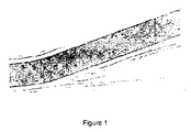
図1に示される下流側圧迫はこれまでに認識されていないメカニズムである。標準的な大腿カニューレの本体により挿入箇所周りの動脈壁が変形する。カニューレは動脈の向きに配置される傾向があることから、カニューレの本体により動脈切開の遠位側縁部が下方に変位し、それにより動脈切開のちょうど遠位側のところの動脈が圧迫される。下流の流れの信頼性を提供するためには、動脈切開のところまでの下流の流れが妨害されることに対処しなければならない。 The downstream compression shown in FIG. 1 is an unrecognized mechanism. A standard femoral cannula body deforms the arterial wall around the insertion site. Since the cannula tends to be placed in the direction of the artery, the body of the cannula displaces the distal edge of the arteriotomy downward, thereby compressing the artery just distal to the arteriotomy . In order to provide downstream flow reliability, the downstream flow up to the arteriotomy must be obstructed.
動脈痙攣および下流側圧迫の問題はこれまでの提案では認識されておらず、また、対処もされていない。 Arterial spasm and downstream compression problems have not been recognized or addressed in previous proposals.
本発明の実施例は、従来のカニューレの1つまたは複数の欠点を解決するかまたは少なくとも改善することを目的とする。 Embodiments of the present invention aim to solve or at least ameliorate one or more disadvantages of conventional cannulas.
本発明によれば、動脈内に挿入するための細長い管状部材を備える二方向灌流用カニューレが提供され、この細長い管状部材が、挿入中に前方を向く管状部材の遠位端にある第1の開口であって、動脈内で挿入方向に血液が流れるのを可能にするように構成される第1の開口と、細長い管状部材内に形成されるエルボーと、エルボーに形成されるかまたはエルボーのわずかに後方に形成され、動脈内で挿入方向に対して概して反対の第2の方向に血液を供給するように構成される第2の開口と、を備える。 In accordance with the present invention, there is provided a bi-directional perfusion cannula comprising an elongate tubular member for insertion into an artery, the elongate tubular member being at a distal end of the tubular member facing forward during insertion. A first opening configured to allow blood to flow in an insertion direction within the artery; an elbow formed in the elongate tubular member; and an elbow formed in or of the elbow A second opening formed slightly posteriorly and configured to supply blood in a second direction generally opposite to the insertion direction within the artery.
好適には、エルボーは、挿入前の弛緩状態でカニューレがその中に、好適には90度から180度の範囲で形成される湾曲したエルボーを有するように、細長い管状部材内に予め形成される。 Preferably, the elbow is preformed in the elongate tubular member so that in a relaxed state prior to insertion, the cannula has a curved elbow formed therein, preferably in the range of 90 to 180 degrees. .
好適には、細長い管状部材はエルボーに少なくとも部分的に形成される突起部を有し、この突起部は、動脈内でカニューレを位置決めするのを容易にするように構成される。好適には、突起部およびエルボーは、動脈をスプリントオープンする移行領域を形成する。一実施形態では、移行領域は膨張可能である。好適には、突起部は挿入方向においてテーパ状であってよく、それによりカニューレを動脈内に挿入することが可能となる。 Preferably, the elongate tubular member has a protrusion at least partially formed on the elbow, the protrusion being configured to facilitate positioning of the cannula within the artery. Preferably, the protrusion and elbow form a transition region that splints the artery. In one embodiment, the transition region is inflatable. Preferably, the protrusion may be tapered in the insertion direction, thereby allowing the cannula to be inserted into the artery.
好適には、突起部の後方部分は挿入方向においてよりも高い割合でテーパ状になっており、それにより、挿入時よりも除去時により強く抵抗するようになっている。突起部の側方プロファイルは肩形状を有することができ、好適には丸みの付いた肩形状を有することができる。 Preferably, the rear portion of the protrusion is tapered at a higher rate than in the insertion direction, thereby resisting more strongly during removal than during insertion. The lateral profile of the protrusion can have a shoulder shape, preferably a rounded shoulder shape.
突起部の断面は概して卵形であってよい。突起部は概してエルボーの外側表面に沿って延在してよい。好適には、第2の開口は突起部を貫通するように延在する。好適には、第2の開口は、管状部材の前方端部から概して離れる方向に延在する。 The cross section of the protrusion may be generally oval. The protrusion may generally extend along the outer surface of the elbow. Preferably, the second opening extends through the protrusion. Preferably, the second opening extends in a direction generally away from the forward end of the tubular member.
細長い管状部材は第1の開口のところで終端する。細長い管状部材は、細長い導入器を中で受けるように構成され、それによりカニューレを挿入するのを補助し、さらに、細長い管状部材および導入器を動脈内に挿入するときに第1の開口を通って血液が流れるのを防止することができる。 The elongate tubular member terminates at the first opening. The elongate tubular member is configured to receive an elongate introducer therein, thereby assisting in insertion of the cannula and further through the first opening when inserting the elongate tubular member and introducer into the artery. Thus, it is possible to prevent blood from flowing.
細長い管状部材は、第2の開口の周りの領域における細長い管状部材の内径が、細長い導入器を中に受け入れるときの細長い導入器の対応する部分の直径より大きくなるように構成され、それにより、血液が第2の開口を介して細長い管状部材内へ通過することができ、そのときに第2の開口が動脈内まで通過したことが示される。好適には、細長い管状部材の内径は、細長い管状部材の長さに沿って概して一定である。 The elongate tubular member is configured such that the inner diameter of the elongate tubular member in the region around the second opening is greater than the diameter of the corresponding portion of the elongate introducer when receiving the elongate introducer therein, thereby Blood can pass through the second opening into the elongated tubular member, at which time it is shown that the second opening has passed into the artery. Preferably, the inner diameter of the elongate tubular member is generally constant along the length of the elongate tubular member.
好適には、エルボーは約130度の角度で湾曲する。細長い管状部材は可撓性材料で形成されてよく、導入器をカニューレ内に挿入するときに少なくとも部分的に直線状となる。細長い管状部材は、ワイヤ強化可撓性ポリウレタン材料で形成されてよい。 Preferably, the elbow is curved at an angle of about 130 degrees. The elongate tubular member may be formed of a flexible material and is at least partially straight when the introducer is inserted into the cannula. The elongate tubular member may be formed of a wire reinforced flexible polyurethane material.
好適には、カニューレは大腿動脈に挿入されるように構成される。また、カニューレは鎖骨下動脈または腋窩動脈に挿入されるようにも構成され得る。 Preferably, the cannula is configured to be inserted into the femoral artery. The cannula can also be configured to be inserted into a subclavian or axillary artery.
カニューレは、圧力変換器に連通されるマノメータチューブをさらに含むことができ、このマノメータチューブは、第2の方向に流れる血液の圧力を測定するように構成される。 The cannula can further include a manometer tube in communication with the pressure transducer, the manometer tube being configured to measure the pressure of blood flowing in the second direction.
また、本発明によれば、上で説明したタイプの二方向灌流用カニューレと、細長い管状部材を通って受けられるテーパ状の導入器とが組み合わせで提供される。 The present invention also provides a combination of a bi-directional perfusion cannula of the type described above and a tapered introducer received through an elongated tubular member.
また、本発明によれば、遠位端にある、動脈内で挿入方向に血液を供給するための第1の開口と、細長い管状部材内に形成されるエルボーと、少なくとも部分的にエルボーに形成される突起部と、動脈内で挿入方向から離れる方向に血液を供給するための、突起部に形成される第2の開口と、を有する細長い管状部材を備える二方向灌流用カニューレを動脈内に挿入するための方法が提供され、この方法が、突起部が動脈内に入ったことを示す挿入時の抵抗が増大するのを感じるまで細長い管状部材の遠位端を動脈内に送るステップと、エルボーおよび突起部が動脈内まで通過して抵抗の大きさが減少するまで、細長い管状部材を動脈内へと低速で送るステップと、突起部が動脈壁に当接されてカニューレが定位置にあることを示す後退時の抵抗が増大するのを感じるまで細長い管状部材を後退させるステップと、を含む。 Also according to the invention, a first opening at the distal end for supplying blood in the direction of insertion within the artery, an elbow formed in the elongate tubular member, and at least partially formed in the elbow A bi-directional perfusion cannula having an elongated tubular member having a protrusion formed in the artery and a second opening formed in the protrusion for supplying blood away from the insertion direction in the artery. A method for insertion is provided, the method comprising delivering the distal end of the elongate tubular member into the artery until it feels increased resistance during insertion indicating that the protrusion has entered the artery; Slowly feeding the elongate tubular member into the artery until the elbow and protrusion pass into the artery and the magnitude of resistance decreases, and the protrusion abuts the artery wall and the cannula is in place Retreating to show that Comprising the steps of anti retracts the elongated tubular member to feel the increase, the.
好適には、第2の開口が動脈内に低速で送られた後、血液が第2の開口を介して細長い管状部材内に流れる。 Preferably, blood flows through the second opening into the elongate tubular member after the second opening is pumped slowly into the artery.
好適には、処置後、カニューレが、動脈の壁を通るように突起部を低速で送ることにより、後退され、それにより、突起部の断面寸法が増大していることにより、動脈壁に形成される開口部が徐々に拡大され、それにより、動脈にさらに外傷を発生させることなく細長い管状部材の全体が除去され得るようになる。 Preferably, after the procedure, the cannula is formed in the arterial wall by being retracted by slowly feeding the projection through the artery wall, thereby increasing the cross-sectional dimension of the projection. The opening is gradually enlarged so that the entire elongated tubular member can be removed without further trauma to the artery.
また、本発明によれば、末梢動脈カニュレーション時に肢部までの灌流を提供する方法が提供され、この方法が、上述したタイプのカニューレを動脈内に挿入するステップと、カニューレを介して動脈まで血液を圧送するステップと、適切なレベルの血液流が肢部に送られるようにするために圧力変換器によって測定される圧力を監視するステップと、を含む。 The present invention also provides a method for providing perfusion to the limb during peripheral arterial cannulation, the method comprising inserting a cannula of the type described above into the artery and via the cannula to the artery. Pumping blood and monitoring the pressure measured by the pressure transducer to ensure that an appropriate level of blood flow is delivered to the limb.
好適な実施形態によれば、第2の方向に流れる血液の圧力が常に監視され、流れの開始時に決定される第2の方向における圧力レベルに近い範囲内で維持される。 According to a preferred embodiment, the pressure of blood flowing in the second direction is constantly monitored and maintained within a range close to the pressure level in the second direction determined at the beginning of the flow.
単に非限定的な例として添付図面を参照しながら本発明をさらに説明する。 The invention will be further described, by way of non-limiting example only, with reference to the accompanying drawings.
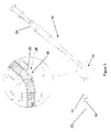
図2を参照すると、動脈内に挿入されるように構成される細長い管状部材12を備える二方向灌流用カニューレ10が示されている。細長い管状部材12は細長い管状部材12の遠位端に第1の開口14を備え、この第1の開口14は、カニューレの動脈内への挿入中に前方を向く。第1の開口14は、血液が挿入方向で動脈内に入るように流れることができ、および患者の動脈循環に向かって流れることができるように構成される。
Referring to FIG. 2, there is shown a
細長い管状部材12はまた、細長い管状部材に形成されるエルボー(elbow)16を備える。エルボー16は、挿入前の弛緩状態でカニューレがその中に曲がったエルボーを有するように、予め形成される。示される実施例では、エルボーは130度の角度で曲がり、この角度は、動脈切開の遠位側の動脈の下流側圧迫を最も良好に軽減し、カニューレが動脈の外側で適切に配置され得るようにすることが分かっている。120度といったように、詳細には90度から180度の範囲内にある別の角度が適切となる可能性があることも認識されたい。この範囲から外れる角度は、下流側圧迫を軽減することにおいて、および、カニューレの血管内セクションおよび血管外セクションが適切に配置されるのを可能にすることにおいて、効果的ではない可能性がある。エルボー16は、後方を向く開口の形態の第2の開口18が二方向灌流のために提供され得るように、細長い管状部材12を適切な量だけ移動させるのを可能にする。
The elongate
Fongerらで開示されるような、上で提示した構成では、動脈壁内ではなく動脈内に血液を誘導する後方を向く開口を設けるのを可能にするようなエルボーが含まれない。発明者らは、動脈が本質的に柔軟性を有しており、従来型のカニューレより剛性が低いことから、使用時に、動脈内に挿入されるときの直線状のカニューレの周りで曲がる傾向があり、したがって図1に示されるように動脈を閉じるように作用する傾向があることを発見した。側方を向く孔を有する構成では特にこの問題が起こりやすい。エルボーおよび後方を向く開口を設けることにより、図7に示されるように、動脈壁により開口が妨害されたり覆われたりするのを回避することが可能となり、カニューレの効果を向上させることができる。詳細には、後方を向く開口が動脈壁から離れていることにより、動脈痙攣および下流側圧迫に関連させて上で考察した問題を軽減することができる。 The configuration presented above, as disclosed by Fonger et al., Does not include an elbow that allows for a backward-facing opening to guide blood into the artery rather than into the artery wall. The inventors have a tendency to bend around a straight cannula when inserted into an artery in use because the artery is inherently flexible and less rigid than a conventional cannula. And therefore found to tend to act to close the artery as shown in FIG. This problem is particularly likely to occur in configurations having holes facing sideways. By providing the elbow and the opening facing rearward, as shown in FIG. 7, it is possible to prevent the opening from being obstructed or covered by the artery wall, and the effect of the cannula can be improved. In particular, the posterior opening away from the artery wall can alleviate the problems discussed above in connection with arterial spasm and downstream compression.
エルボー16はまた、大腿動脈から脚部の表面にまで通過するときにカニューレ10を位置決めするのを補助する。エルボー16で使用される角度は、下流側圧迫または遠位側動脈圧迫の量を低減するように選択される。
The
示されるように、第2の開口18はエルボー16に形成されるかまたはエルボー16のわずかに後方に形成され、すなわち、挿入方向または前方方向から離れる方に形成される。第2の開口18は後方を向き、動脈内で二方向灌流を実現することを目的として前方方向または挿入方向に概して反対の第2の方向において動脈内に血液を供給するように構成される。示される実施例では、第2の開口18はエルボーに形成されるが、エルボーのわずかに後方に形成されてもよく、その場合でも動脈内に二方向灌流を適切に実現することができる。エルボー16またはそのわずか後方に第2の開口18を形成することにより、細長い管状部材12の内腔に衝突したりまたはその内腔を狭めたりすることなく血液の流れのための第2の経路を形成することが可能となり、それによりカニューレ10を通る血液流量が減少することが回避される。エルボー16および第2の開口18の構成は、カニューレ10が動脈内に挿入されるときに第2の開口18が動脈内で正確に方向付けられるように形成される。
As shown, the
細長い管状部材12はエルボー16に形成される突起部20を有し、この突起部20は、カニューレ10が動脈内に挿入されることおよびカニューレ10を動脈内で位置決めするのを容易にするように構成される。突起部20はエルボー16の外側表面上に形成されてその外側表面に沿って延在する。図6Aから6Cに見られるように、突起部20の大きさは概して断面の下側半分までに制限され、これは、正面図(図4)すなわちカニューレ10の上方からは見ることはできない。
The elongate
突起部20は、外傷を最小にしながら動脈内にカニューレを挿入するのを可能にするために挿入方向にテーパ状になっている。これに関して、このテーパは、カニューレ10が挿入されるときに動脈壁が徐々に拡張するのを可能にするように、緩やかになっている。テーパの角度は約3度から25度の間である。カニューレのサイズが異なる場合、テーパの角度は同じであるが、突起部の最大厚さがカニューレのサイズに応じて変化する。例えば、20Fカニューレは、突起部が形成されるところの細長い管状部材の厚さを除いて、約1.5mmの最大厚さの突起部を有する。より小型のカニューレ上に形成される突起部のサイズはスケールダウンされてより小型になることを認識されたい。
The
突起部20のサイズは、外傷を最小にしながら動脈内にカニューレ10を挿入するのを可能にするような十分な小ささであるが、カニューレ10が誤って移動(dislodge)させられるのを防止するのに十分なほど大きいものである。また、突起部20のサイズは、第2の開口18が突起部20内に配置されるのを可能にするのに十分で、それにより動脈内で第2の開口18が方向付けされ得るようになる。
The size of the
突起部20およびエルボー16は共に移行領域28を形成し、ここでは、細長い管状部材12の断面サイズが徐々に増大してその後に縮小し、それにより、動脈壁に対する外傷を最小にしながら細長い管状部材12を動脈内に挿入することが可能となる。示される実施例では、図6A、6Bおよび6Cに見られるように、突起部20は断面が概して卵形であるが、別の形状も使用され得る。
The
移行領域28は動脈をスプリントオープン(splint open)するように作用し、それにより、動脈がカニューレの本体によって圧迫されなくなり、第2の方向の流れが妨害されなくなる。移行領域28は、第2の開口18から離れるように動脈壁をサポートするように作用し、それにより、動脈が開いた状態で保持され、動脈がカニューレ10から動脈内への血液の流れを遮断しなくなる。移行領域28はまた、カニューレ10が動脈内に挿入されるときにカニューレ10に安定性をもたらし、それによりカニューレ10が定位置で維持されるようになる。
The
突起部20の後方部分は挿入方向におけるよりも高い割合でテーパ状になっており、それにより挿入時よりも除去時に強く抵抗するようになっている。突起部20の後方部分がより鋭くテーパ状になっていることにより、突起部20の側方プロファイル(輪郭)は丸みの付いた肩(shoulder)形状を概して有する。
The rear portion of the
発明者らは、丸みの付いた肩形状の突起部を設けることにより、除去中の動脈の外傷を最小にすることと除去に対する抵抗との間に良好なバランスがもたらされ得ることを発見した。また、突起部は自己配置機構でもある。この点に関して、カニューレが除去されることに対する抵抗が強くなることにより、外科医は、抵抗が弱くなる所定の深さまでわずかな抵抗を受けるだけでカニューレ10を挿入することができるようになる。次いで、カニューレ10は、抵抗が強まることが感じられるまでわずかに後退され、それにより、カニューレが動脈内で正確に配置されたことを示す直接的な触覚フィードバックが得られる。また、除去されることに対する抵抗が強くなることにより、カニューレ10が動脈から誤って後退したりまたは意図せず後退したりすることが防止される。第2の開口18が動脈の外側に移動すると、血液がカニューレから動脈の外側に流れて出血を引き起こす可能性があることから、これは重要である。
The inventors have discovered that providing a rounded shoulder-shaped protrusion can provide a good balance between minimizing arterial trauma during removal and resistance to removal. . The protrusion is also a self-arrangement mechanism. In this regard, the increased resistance to removal of the cannula allows the surgeon to insert the
丸みの付いた肩形状の突起部を設けることにより、挿入中および除去中に出血を引き起こすような通路を形成する可能性がある隆起、レールまたはバーブが回避される。 Providing rounded shoulder-shaped protrusions avoids ridges, rails or barbs that can create passageways that can cause bleeding during insertion and removal.
突起部20の後方部分は第2の開口18から所定の距離に配置され、ここでは、カニューレ10が動脈内の所望される位置に配置されると、第2の開口18が動脈内で適切に位置決めされる。
The posterior portion of the
突起部20の後方部分は足場(scaffold)として機能するように動脈切開に接触するように位置し、下流側の動脈を効果的にステントオープン(stenting open)する。このようにしない場合、下流側の動脈がカニューレの形状に従って移動して下流側の動脈を圧迫し、可能性として、動脈に沿う側部灌流孔からの流れを閉塞する。動脈をステントオープンすることにより、突起部が、血液が妨害されずに脚部に流れることができる通路を維持する。
The posterior portion of the
示される実施例では、図3に見られるように、第2の開口18は、突起部20を通って、管状部材の前方端部から概して離れる方向に延在し、それにより、概して妨害されない下肢部までの流れが提供されるようになる。カニューレのサイズおよびカニューレを受け入れることになる動脈の大きさにより、突起部が第2の開口18を概して囲むようになり、それにより、カニューレが動脈内で位置決めされるときに、第2の開口18が動脈内で適切に配置されるようになる。
In the embodiment shown, as seen in FIG. 3, the
図2に見られるように、細長い管状部材12の内腔の内部にある第2の開口18の最も内側の部分は概して漏斗形状であり、それにより、細長い管状部材12内で第2の開口18を通って流れる血液の乱流が最小となる。第2の開口18のサイズは、下肢部までの多様な割合の流れを実現するために多様なサイズの細長い管状部材に応じて変化してよい。示される実施例では、第2の開口18の直径は2.0mmである。
As can be seen in FIG. 2, the innermost portion of the
図2に見られるように、細長い管状部材12は第1の開口14のところで終端する。また、細長い管状部材12が、第1の開口14の近位側の領域内の前方端部のところでテーパ状になっていることが分かるであろう。可撓性の細長い導入器22が細長い管状部材12を通って受け入れられ、その先端が第1の開口14を通って外に出ることができる。導入器22は、第1の開口14から外に突出するテーパ状の端部を提供することにより、動脈内への挿入を補助する。また、導入器は血液が第1の開口14から逆流するのを防止する。第1の開口14は、導入器22が細長い管状部材12内で受けられているときに第1の開口14を通って細長い管状部材12内まで血液が流れるのを防止するために、細長い管状部材12を通って受けられる導入器22に係合されるように構成される。
As seen in FIG. 2, the
図7に見られるように、細長い管状部材12は、第2の開口18の周りの領域における細長い管状部材12の内径が、そこを通って細長い導入器22を受けるときの細長い導入器22の対応する部分の直径より大きく、それにより、血液が第2の開口18を介して細長い管状部材12内へ通過することができ、そのときに第2の開口18が動脈21内まで通過したことが示されるように構成され得る。この点に関して、細長い導入器22は細長い管状部材内に挿入されたときに第2の開口18の領域で狭まり、それにより、細長い管状部材12内に血液が入ることが可能となる。細長い管状部材12の内径は細長い管状部材12の長手方向に沿って概して一定である。
As seen in FIG. 7, the
第2の開口18が動脈内へと通過するときに、結果として起こる細長い管状部材12に入る血液のフラッシュ(flash;急な流れ)は、カニューレ10がほぼ定位置にあることを示す視覚的表示を医師に提供する。このように血液がフラッシュすることは、経皮挿入時に特に有用である。カニューレ10をこの位置から動脈21内にわずかにさらに挿入することにより、突起部20の後方部分が動脈内へと通過することが可能となる。この後方部分が動脈21内へと通過すると、突起部20のより鋭いテーパ状のこの後方部分が、誤って後退することまたは意図せず後退することを防止するように働く。
As the
図6Aに見られるように、突起部20の前方および第1の開口14の近位側のテーパ状の後方では、突起部20内に移行する(図6B)前の細長い管状部材12の外径は概して一定である。細長い管状部材12の直径は、図6Cに見られるように、突起部20の後方でこの一定の値に移行する、または戻る。細長い管状部材12のサイズは患者に適切な血液流を提供するように選択され、細長い管状部材の外径は約3mmから約8mmの間であってよい。患者の大きさおよび使用される細長い管状部材のサイズによっては、カニューレの本体の周りで流れが妨げられる可能性がある。
As seen in FIG. 6A, at the front of the
細長い管状部材12は、導入器122がカニューレ10内に挿入されるときに少なくも部分的に直線状となるように、可撓性材料から形成され、それにより、カニューレ10を動脈内に挿入することが容易になる。導入器22が除去されると、細長い管状部材12はその元の形状に戻り、上で考察したように動脈をスプリントオープンする。細長い管状部材12は、導入器22がカニューレ10内に挿入されるときは、ほぼ完全に直線状になってよい。図2に見られるように、細長い管状部材12はワイヤ強化材料で形成される。説明する実施例では、細長い管状部材は概して透明の可撓性ポリウレタン材料で形成されるが、シリコーンなどの別の材料が使用されてもよいことを認識されたい。
The elongate
一部の実施例では、カニューレ10の異なるセクションは異なる材料から作られてよい。例えば、エルボー16は細長い管状部材12とは異なる材料から形成されてよい。また、エルボー16は、PVC、ポリウレタン、シリコーンまたはゴムなどの、可撓性材料から形成されてよく、拡張可能となるように構成されてよい。拡張可能なエルボーは手動で膨張されるように構成されてよく、または、自己膨張するように構成されてもよい。このような実施例では、エルボー16は、挿入時は非膨張状態または一部膨張状態に留まることができ、使用に備える際に概して上で説明した形状となるように膨張する。この点に関して、膨張可能なエルボーは、定位置で膨張したときに、二方向灌流が達成され得るように突起部20を提供し、第2の開口18を収容する。膨張可能なエルボーは動脈の内壁に接触して膨張するように構成されてもよく、それにより、カニューレが定位置で保持されるようになり、動脈の内壁が第2の開口18から離間されて維持されるようになる。
In some embodiments, different sections of
カニューレ10の近位端24は標準的な9.5mm(3/8インチ)のコネクタを有するように示されている。このような一般的な取付具が使用されてもよいが、カニューレ10を別の灌流用管類と共に使用するのを可能にするために別の市販される取付具が代用されてもよい。
The
上に記述した実施形態は、概してカニューレ10を動脈内に挿入することに関連させて説明してきた。カニューレ10が経皮的な外科的露出(open surgical exposure)を用いて動脈内に直接的に挿入されることに適し、さらには経皮使用に適することを認識されたい。
The embodiments described above have generally been described in connection with inserting
何日にもわたって継続される可能性がある経皮使用時では、十分な灌流が維持されるようにカニューレを動脈内で正確に配置して留めておくことが望まれる。十分な灌流が維持されるようにするために、カニューレの後方で動脈内に流れ込んで肢部に向かう血液の圧力、すなわち、患者の動脈循環から離れる方に流れる灌流血液を監視することができる。 During percutaneous use, which can continue for days, it is desirable to keep the cannula accurately positioned within the artery so that sufficient perfusion is maintained. To maintain sufficient perfusion, the pressure of blood flowing into the artery behind the cannula and toward the limb, i.e., the perfused blood flowing away from the patient's arterial circulation, can be monitored.
図8Aおよび8Bは、下流側の流れの妥当性およびカニューレ10の位置を示すための、肢部に向かって流れる灌流血液の圧力を監視するための構成の一実施例を示す。示される実施例では、マノメータチューブ30が細長い管状部材12に隣接して延在する。マノメータチューブ30は突起部20の後方のところの位置で細長い管状部材の壁を挿入方向に通る。この位置は使用時には患者の外部にくる。マノメータチューブ30が突起部20の後方の別の位置のところで細長い管状部材の壁を通過してもよく、その場合でもマノメータチューブ30と圧力変換器との間での必要な連通が得られることを認識されたい。マノメータチューブ30は細長い管状部材12内を通り、第2の開口18に隣接する開口32のところで終端する。開口32の位置は、肢部に向かって流れる血液の圧力を監視することができるような位置である。
FIGS. 8A and 8B show one example of a configuration for monitoring the pressure of perfused blood flowing towards the limb to indicate the validity of the downstream flow and the position of the
マノメータチューブ30は、マノメータチューブ30と圧力変換器(図示せず)との間での接続を可能にするためのコネクタ34を受け入れるように構成される。使用時、カニューレ10が動脈内に挿入されると、血液が開口18を通って患者の動脈内に流れて肢部に向かって流れる。圧力変換器がこの肢部に向かって流れる血液の圧力を測定し、それにより、肢部に向かう流量が十分であるかどうかの決定が行われ得る。この場合、カニューレが動脈内で正確に配置されたかどうかを示すのに、圧力変換器からの読取値が使用され得る。この点に関して、カニューレが動脈内で正確に配置されている場合、この圧力読取値により、開口14から細長い管状部材を通って拍動流が伝達されていることが、最初に実証される。非拍動流が細長い管状部材を通り始めると、圧力の傾向および絶対圧力を監視することで、肢部に向かう灌流内の任意の変化が示される。カニューレは不正確に配置されることで動脈内に過度に深く挿入される可能性があり、そのような場合、第2の開口が覆われる可能性があり、または、カニューレが十分に挿入されない可能性もあり、その場合、第2の開口は動脈内に配置されず、動脈内にはわずかな流れしか流れないかまたは動脈内への流れがなくなる。
The
また、圧力変換器は、カニューレ10の初期配置が正確であるかどうかを確認するのにも使用され得る。
The pressure transducer can also be used to check whether the initial placement of the
圧力変換器を使用することは、Extra Corporeal Membrane Oxygenation(ECMO)ユニットおよび集中治療ユニットなどの灌流が長期間になることが一般的であるような環境で有益である可能性がある。 The use of pressure transducers can be beneficial in environments where perfusion is typically prolonged, such as Extra Corporate Membrane Oxygenation (ECMO) units and intensive care units.
カニューレ10およびテーパ状の導入器22を動脈内に挿入するのを可能にするために、既知のガイドワイヤ技術が使用される。
Known guidewire techniques are used to allow
二方向灌流用カニューレ10を動脈内に挿入するための方法は、突起部20が動脈内に入ったことを示す挿入時の抵抗が増大するのを感じるまで、導入器22を受け入れている状態の細長い管状部材12の遠位端を動脈内に送るステップを含む(拡張器を用いて動脈を予め拡張した後でガイドワイヤを用いる)。次いで、エルボー16および突起部20が動脈内まで通過して抵抗の大きさが減少するまで、細長い管状部材12が動脈内へと低速で送られる(ease)。次いで、突起部20が動脈壁に当接されてカニューレ10が定位置にあることを示す、後退時の抵抗が増大するのを感じるまで、細長い管状部材12が後退される。
The method for inserting the
カニューレが定位置にくると、導入器22が除去され、カニューレ10が適切な灌流機器に接続され得るようになる。
When the cannula is in place, the
処置後、カニューレ10が、動脈の壁を通るように突起部20を低速で送ることにより、後退され、それにより、突起部20の断面サイズが増大していることにより、動脈壁内に形成される開口部が徐々に拡大され、それにより、動脈にさらに外傷を発生させることなく細長い管状部材12の全体が除去され得るようになる。細長い管状部材が後退され得るようにすることを目的として突起部が動脈壁を通過するのを補助するために、遠位位置のところで大腿動脈に圧力を加えることができる。
After the procedure, the
これらの実施形態は単に例として説明されるものであり、開示される本発明の範囲内で修正を行うことが可能である。 These embodiments are described by way of example only and modifications can be made within the scope of the disclosed invention.
Claims (13)
挿入中に前方を向く前記細長い管状部材の遠位端にある第1の開口であって、前記動脈内で挿入方向に血液が流れるのを可能にするように構成される第1の開口と、
前記細長い管状部材に形成されるエルボーと、
前記エルボーに少なくとも部分的に形成される突起部であって、前記動脈内で前記カニューレを位置決めするのを容易にするように形成される突起部と、
前記エルボーに形成されるかまたは前記エルボーのわずかに後方に形成され且つ前記突起部を貫通するように延在し、挿入方向に対して概して反対の第2の方向で前記動脈内に血液を供給するように構成される第2の開口と
を備える、二方向灌流用カニューレ。 A bi-directional perfusion cannula comprising an elongate tubular member inserted into an artery, the elongate tubular member comprising:
A first opening at a distal end of the elongated tubular member facing forward during insertion, the first opening configured to allow blood to flow in the insertion direction within the artery;
An elbow formed in the elongated tubular member;
A protrusion formed at least partially on the elbow, the protrusion formed to facilitate positioning the cannula within the artery;
Supplying blood into the artery in a second direction that is formed in the elbow or slightly behind the elbow and extends through the protrusion , generally opposite the insertion direction Bei El and a second opening configured to bi-directional perfusion cannula.
Applications Claiming Priority (5)
| Application Number | Priority Date | Filing Date | Title |
|---|---|---|---|
| AU2011901258A AU2011901258A0 (en) | 2011-04-05 | Bi-directional perfusion cannula | |
| AU2011901258 | 2011-04-05 | ||
| AU2011902210 | 2011-06-03 | ||
| AU2011902210A AU2011902210A0 (en) | 2011-06-03 | Bi-directional perfusion cannula | |
| PCT/AU2012/000347 WO2012135904A1 (en) | 2011-04-05 | 2012-04-04 | Bi-directional perfusion cannula |
Publications (3)
| Publication Number | Publication Date |
|---|---|
| JP2014517721A JP2014517721A (en) | 2014-07-24 |
| JP2014517721A5 JP2014517721A5 (en) | 2014-11-27 |
| JP5932969B2 true JP5932969B2 (en) | 2016-06-08 |
Family
ID=46966653
Family Applications (1)
| Application Number | Title | Priority Date | Filing Date |
|---|---|---|---|
| JP2014502955A Expired - Fee Related JP5932969B2 (en) | 2011-04-05 | 2012-04-04 | Bidirectional perfusion cannula |
Country Status (8)
| Country | Link |
|---|---|
| US (4) | US8795253B2 (en) |
| EP (2) | EP2694148B1 (en) |
| JP (1) | JP5932969B2 (en) |
| CN (1) | CN103635223B (en) |
| AU (1) | AU2012239851B2 (en) |
| BR (1) | BR112013025854B1 (en) |
| CA (1) | CA2832214C (en) |
| WO (1) | WO2012135904A1 (en) |
Families Citing this family (47)
| Publication number | Priority date | Publication date | Assignee | Title |
|---|---|---|---|---|
| US20110152741A1 (en) * | 2009-12-21 | 2011-06-23 | Michael Banchieri | Cannula system |
| US9339599B2 (en) * | 2009-12-21 | 2016-05-17 | Sorin Group Usa, Inc. | Self-dilating cannula |
| US8795253B2 (en) | 2011-04-05 | 2014-08-05 | Sorin Group Italia S.R.L. | Bi-directional perfusion cannula |
| WO2014043704A1 (en) * | 2012-09-17 | 2014-03-20 | Boston Scientific Scimed, Inc. | Pressure sensing guidewire |
| US12042610B2 (en) | 2014-01-30 | 2024-07-23 | Tar Toong Victor Chao | Arterial sheath which allows distal perfusion within a cannulated vessel |
| US20170007800A1 (en) * | 2014-01-30 | 2017-01-12 | Singapore Health Services Pte Ltd | Arterial cannula which allows proximal and distal perfusion within a cannulated vessel |
| WO2015116004A1 (en) * | 2014-01-30 | 2015-08-06 | Singapore Health Services Pte Ltd | Arterial sheath which allows distal perfusion within a cannulated vessel |
| US10226595B2 (en) | 2014-06-16 | 2019-03-12 | Edwards Lifesciences Corporation | Spring cannulae |
| US20170232238A1 (en) | 2014-08-06 | 2017-08-17 | Edwars Litesciences Corporation | Multi-lumen cannulae |
| CN104208802A (en) * | 2014-10-02 | 2014-12-17 | 黄晓 | Axillary artery and femoral artery cannula without perfusion ischemia area and application of cannula |
| US9981119B2 (en) * | 2014-10-29 | 2018-05-29 | Edwards Lifesciences Corporation | Bi-directional cannula |
| KR20160103474A (en) | 2015-02-24 | 2016-09-01 | 사회복지법인 삼성생명공익재단 | Femoral arterial Cannula capable of guidance of bidirectional flow |
| JP6669898B2 (en) | 2016-02-23 | 2020-03-18 | ボストン サイエンティフィック サイムド,インコーポレイテッドBoston Scientific Scimed,Inc. | Pressure sensing guidewire system with optical connector cable |
| FR3058642B1 (en) * | 2016-11-15 | 2023-03-10 | Hopitaux Paris Assist Publique | CANNULA AND OXYGENATION SYSTEM BY EXTRACORPORAL MEMBRANE COMPRISING SUCH CANNULA |
| CN106730269B (en) * | 2016-12-30 | 2019-09-03 | 杭州广硕医疗科技有限公司 | A kind of peripheral arterial Intubaction device of two-way filling |
| TR201704099A2 (en) | 2017-03-17 | 2018-09-21 | T C Istanbul Medipol Ueniversitesi | A FEMORAL ARTERIAL ECMO (EXTRACORPOREAL MEMBRANE OXYGENATION EXTRACORPOREAL MEMBRANE OXYGENATION) CANNULA |
| IT201700085305A1 (en) * | 2017-07-26 | 2019-01-26 | Eday S R L | BIDIRECTIONAL PERFUSION CANNULA |
| AU2018311951B2 (en) | 2017-08-03 | 2020-10-15 | Boston Scientific Scimed, Inc. | Systems for assessing fractional flow reserve |
| IT201700110730A1 (en) * | 2017-10-03 | 2019-04-03 | Paolo Peruzzo | CANNULA FOR THE PERFUSION OF A FLUID |
| US11364333B2 (en) | 2017-10-10 | 2022-06-21 | University Of Maryland, Baltimore | Bidirectional flow catheter |
| CN108434600B (en) * | 2018-02-26 | 2021-11-02 | 郭成军 | Intracardiac implant, cardiac pacemaker, implant device |
| EP3755215B1 (en) | 2018-02-23 | 2022-07-20 | Boston Scientific Scimed Inc. | System for assessing a vessel with sequential physiological measurements |
| EP3768156B1 (en) | 2018-03-23 | 2023-09-20 | Boston Scientific Scimed, Inc. | Medical device with pressure sensor |
| US11559213B2 (en) | 2018-04-06 | 2023-01-24 | Boston Scientific Scimed, Inc. | Medical device with pressure sensor |
| EP3773854B1 (en) | 2018-04-11 | 2024-07-24 | Livanova USA, Inc. | Cannula fixation device |
| US11666232B2 (en) | 2018-04-18 | 2023-06-06 | Boston Scientific Scimed, Inc. | Methods for assessing a vessel with sequential physiological measurements |
| EP3897801A2 (en) | 2018-12-21 | 2021-10-27 | Abiomed, Inc. | Persistent perfusion sheath |
| FR3092000B1 (en) * | 2019-01-28 | 2023-02-24 | Hopitaux Paris Assist Publique | INJECTION CANNULA, FLUID INJECTION SYSTEM |
| WO2020161586A1 (en) | 2019-02-04 | 2020-08-13 | Contract Medical International Gmbh | Systems and methods for diverting blood flow in blood vessels |
| CN109999247A (en) * | 2019-04-26 | 2019-07-12 | 山东省千佛山医院 | A kind of Bidirectional Blood Flow arterial cannulation |
| EP3735996B1 (en) | 2019-05-07 | 2023-09-27 | Free Life Medical GmbH | Bi-directional perfusion cannula |
| CN110075382B (en) * | 2019-05-29 | 2024-04-19 | 浙江伏尔特医疗器械股份有限公司 | Multifunctional non-PVC material transfusion system |
| KR102032447B1 (en) | 2019-07-26 | 2019-10-15 | 사회복지법인 삼성생명공익재단 | Femoral arterial Cannula capable of guidance of bidirectional flow |
| US12037458B2 (en) * | 2019-09-06 | 2024-07-16 | Elkem Silicones USA Corp. | Process and premix for incorporating optical brighteners into a polymeric composition |
| KR102359614B1 (en) * | 2020-07-20 | 2022-02-08 | 인제대학교 산학협력단 | Elastic membrane fixing type bidirectional arterial cannula |
| WO2021049847A1 (en) * | 2019-09-11 | 2021-03-18 | 인제대학교 산학협력단 | Medical instrument for vascular surgery having medical conduit and connection port enabling bidirectional fluid flow |
| IT201900016466A1 (en) | 2019-09-17 | 2021-03-17 | Andrea Ugolini | CANNULA FOR MEDICAL USE, IN PARTICULAR FOR INSERTION IN ARTERIES. |
| USD975844S1 (en) | 2019-11-06 | 2023-01-17 | Free Life Medical Gmbh | Cannula |
| FR3103109A1 (en) * | 2019-11-18 | 2021-05-21 | Novaflow | Bidirectional arterial cannula for extracorporeal membrane oxygenation and method of using such a cannula |
| TWI724682B (en) * | 2019-12-11 | 2021-04-11 | 林伯彥 | Bidirectional vascular tube device |
| CN113082452B (en) * | 2020-01-08 | 2023-02-17 | 西安西京医疗用品有限公司 | Femoral artery cannula |
| EP3861946B1 (en) * | 2020-05-28 | 2022-06-08 | Medinice S.A. | Cannula for percutaneous minimally invasive cannulation of the vena cava |
| CN112915294B (en) * | 2021-01-25 | 2024-05-07 | 安徽医科大学第一附属医院 | VA-ECMO femoral artery cannula for providing lower limb blood perfusion and catheterization method |
| US12087000B2 (en) | 2021-03-05 | 2024-09-10 | Boston Scientific Scimed, Inc. | Systems and methods for vascular image co-registration |
| EP4108268A1 (en) | 2021-06-22 | 2022-12-28 | Jawad Salman | Bi-directional cannula |
| US12029889B2 (en) | 2022-04-01 | 2024-07-09 | Tulyp Medical Sas | Perfusion systems and methods for monitoring tissue oxygenation and reducing limb ischemia |
| US20230355923A1 (en) * | 2022-05-04 | 2023-11-09 | Abiomed, Inc. | Introducer sheath with peel away perfusion aperture |
Family Cites Families (66)
| Publication number | Priority date | Publication date | Assignee | Title |
|---|---|---|---|---|
| US3938501A (en) * | 1972-01-11 | 1976-02-17 | Siemens Aktiengesellschaft | Catheter for radiological renal aortography and selective arteriography |
| US4114618A (en) * | 1976-12-15 | 1978-09-19 | Vargas Jorge J | Catheter assembly |
| US4129129A (en) | 1977-03-18 | 1978-12-12 | Sarns, Inc. | Venous return catheter and a method of using the same |
| US4180068A (en) | 1978-04-13 | 1979-12-25 | Motion Control, Incorporated | Bi-directional flow catheter with retractable trocar/valve structure |
| US4248224A (en) * | 1978-08-01 | 1981-02-03 | Jones James W | Double venous cannula |
| US4639252A (en) | 1985-04-05 | 1987-01-27 | Research Medical, Inc. | Venous return catheter |
| US4790315A (en) * | 1986-09-02 | 1988-12-13 | Advanced Cardiovascular Systems, Inc. | Perfusion dilatation catheter and method of manufacture |
| US5058580A (en) | 1988-05-11 | 1991-10-22 | Hazard Patrick B | Percutaneous tracheostomy tube |
| US4994027A (en) * | 1988-06-08 | 1991-02-19 | Farrell Edward M | Percutaneous femoral bypass system |
| US4895564A (en) * | 1988-06-08 | 1990-01-23 | Farrell Edward M | Percutaneous femoral bypass system |
| US5011469A (en) | 1988-08-29 | 1991-04-30 | Shiley, Inc. | Peripheral cardiopulmonary bypass and coronary reperfusion system |
| US5190528A (en) | 1990-10-19 | 1993-03-02 | Boston University | Percutaneous transseptal left atrial cannulation system |
| US5308325A (en) | 1991-01-28 | 1994-05-03 | Corpak, Inc. | Retention balloon for percutaneous catheter |
| AR245376A1 (en) * | 1991-02-25 | 1994-01-31 | Liliana Rosa Grinfeld Y Robert | Arterial profusion nozzle, for extra-corporal circulation and other uses. |
| US5584803A (en) | 1991-07-16 | 1996-12-17 | Heartport, Inc. | System for cardiac procedures |
| JP2979804B2 (en) * | 1991-12-13 | 1999-11-15 | 株式会社ニッショー | Aortic occlusion balloon catheter |
| US5171218A (en) * | 1992-01-02 | 1992-12-15 | Trustees Of Boston University | Bidirectional femoral arterial cannula |
| US5522834A (en) | 1992-10-15 | 1996-06-04 | Applied Medical Resources Corporation | Internal mammary artery catheter and method |
| US6090072A (en) * | 1992-10-15 | 2000-07-18 | Scimed Life Systems, Inc. | Expandable introducer sheath |
| US5354276A (en) | 1993-03-18 | 1994-10-11 | Applied Medical Resources Corporation | Internal mammary artery catheter and method |
| US5402799A (en) | 1993-06-29 | 1995-04-04 | Cordis Corporation | Guidewire having flexible floppy tip |
| US5569218A (en) * | 1994-02-14 | 1996-10-29 | Scimed Life Systems, Inc. | Elastic guide catheter transition element |
| GB9425493D0 (en) | 1994-12-16 | 1995-02-15 | Imperial College | Modified cannula |
| US5980503A (en) | 1996-04-08 | 1999-11-09 | Guidant Corporation | Endoscopic cardioplegia infusion cannula and method of use |
| US7678098B2 (en) | 1996-04-10 | 2010-03-16 | Endoscopic Technologies, Inc. | Venous cannula and cardiopulmonary bypass system |
| US5868703A (en) | 1996-04-10 | 1999-02-09 | Endoscopic Technologies, Inc. | Multichannel catheter |
| US6048331A (en) * | 1996-05-14 | 2000-04-11 | Embol-X, Inc. | Cardioplegia occluder |
| US5928192A (en) * | 1997-07-24 | 1999-07-27 | Embol-X, Inc. | Arterial aspiration |
| US6695810B2 (en) | 1997-11-21 | 2004-02-24 | Advanced Interventional Technologies, Inc. | Endolumenal aortic isolation assembly and method |
| USD408529S (en) | 1997-12-23 | 1999-04-20 | Fibrasonics Inc. | Cannula for ultrasonic probe |
| US6179827B1 (en) | 1998-03-16 | 2001-01-30 | Chase Medical | Catheter having integral expandable/collapsible lumen |
| WO2000004942A1 (en) | 1998-07-21 | 2000-02-03 | Heartport, Inc. | Multi-lumen catheters and methods of use and manufacture |
| US6126594A (en) | 1998-07-21 | 2000-10-03 | Bayer; Izhack | Anoscope for internal hemorrhoidectomy |
| US6129713A (en) | 1998-08-11 | 2000-10-10 | Embol-X, Inc. | Slidable cannula and method of use |
| US6837864B1 (en) | 1999-02-19 | 2005-01-04 | Endoscopic Technologies, Inc. | Multichannel catheter with obturator |
| US6186981B1 (en) * | 1999-03-23 | 2001-02-13 | Peter Cho | Cavo-atrial cannula |
| US6497698B1 (en) | 1999-05-20 | 2002-12-24 | Cardiac Assist, Inc. | Method and apparatus for treating a patient |
| US6676650B1 (en) * | 1999-09-22 | 2004-01-13 | Cardiacassist, Inc. | Perfusion cannula, method and system |
| US6592567B1 (en) * | 1999-12-07 | 2003-07-15 | Chf Solutions, Inc. | Kidney perfusion catheter |
| CA2366813A1 (en) | 2000-01-26 | 2001-08-02 | Heartport, Inc. | Vascular incisor and method |
| US7056294B2 (en) | 2000-04-13 | 2006-06-06 | Ev3 Sunnyvale, Inc | Method and apparatus for accessing the left atrial appendage |
| WO2002005865A2 (en) * | 2000-07-14 | 2002-01-24 | Sub-Q, Inc. | Sheath-mounted arterial plug delivery device |
| US6626872B1 (en) * | 2000-09-12 | 2003-09-30 | Jose A. Navia | Perfusion cannula |
| US6858019B2 (en) | 2001-01-09 | 2005-02-22 | Rex Medical, L.P. | Dialysis catheter and methods of insertion |
| US20020133128A1 (en) | 2001-03-16 | 2002-09-19 | Heller Andrew S. | Method and apparatus for dilating an orifice in biological tissue |
| US20020188167A1 (en) * | 2001-06-06 | 2002-12-12 | Anthony Viole | Multilumen catheter for minimizing limb ischemia |
| US20030216688A1 (en) | 2002-05-20 | 2003-11-20 | Huybregts M.A.J.M. | Cooling cannula system and method for use in cardiac surgery |
| US20040102730A1 (en) | 2002-10-22 | 2004-05-27 | Davis Thomas P. | System and method for facilitating hemostasis of blood vessel punctures with absorbable sponge |
| US7473239B2 (en) | 2003-08-25 | 2009-01-06 | The University Of Texas System | Single expandable double lumen cannula assembly for veno-venous ECMO |
| WO2005037345A2 (en) | 2003-10-17 | 2005-04-28 | Vanderbilt University | Percutaneously-inserted ventricular assist devices and related methods |
| DE602004026114D1 (en) | 2004-01-16 | 2010-04-29 | Top Kk | indwelling |
| USD533270S1 (en) | 2004-07-15 | 2006-12-05 | Children's Medical Center Corporation | Introducer cannula and cannula straightener |
| US8613728B2 (en) | 2005-11-07 | 2013-12-24 | Flexicath Ltd. | Removable adapter for a splittable introducer and method of use thereof |
| EP1984056A1 (en) * | 2006-02-15 | 2008-10-29 | Wilson-Cook Medical Inc. | Catheter aperture with attachable structure |
| WO2007134394A1 (en) * | 2006-05-22 | 2007-11-29 | Uscom Limited | Cardiac measurement system and method |
| MX2009000876A (en) | 2006-08-02 | 2009-02-04 | Unomedical As | Insertion device. |
| CA2666881C (en) | 2006-08-30 | 2015-03-24 | Circulite, Inc. | Devices, methods and systems for establishing supplemental blood flow in the circulatory system |
| US9168355B2 (en) * | 2006-09-29 | 2015-10-27 | Covidien Lp | Acute hemodialysis catheter assembly |
| ES2690306T3 (en) | 2006-11-28 | 2018-11-20 | F. Hoffmann-La Roche Ag | An insertion device and method to insert an insert subcutaneously into a body |
| US8123739B2 (en) | 2008-08-19 | 2012-02-28 | Cook Medical Technologies Llc | Drainage catheter and method for catheterizing a patient |
| CN201257222Y (en) * | 2008-09-12 | 2009-06-17 | 段大为 | Double-stage multifunctional femoral cannula |
| WO2011003043A1 (en) | 2009-07-01 | 2011-01-06 | The Penn State Research Foundation | Blood pump with expandable cannula |
| US20110152741A1 (en) | 2009-12-21 | 2011-06-23 | Michael Banchieri | Cannula system |
| US9339599B2 (en) | 2009-12-21 | 2016-05-17 | Sorin Group Usa, Inc. | Self-dilating cannula |
| CN201631866U (en) * | 2010-01-29 | 2010-11-17 | 谢新正 | Core bipolar femoral artery spile for thoracoscopic cardiac surgery |
| US8795253B2 (en) | 2011-04-05 | 2014-08-05 | Sorin Group Italia S.R.L. | Bi-directional perfusion cannula |
-
2012
- 2012-03-13 US US13/418,473 patent/US8795253B2/en active Active
- 2012-04-04 CN CN201280027491.8A patent/CN103635223B/en active Active
- 2012-04-04 CA CA2832214A patent/CA2832214C/en not_active Expired - Fee Related
- 2012-04-04 WO PCT/AU2012/000347 patent/WO2012135904A1/en active Application Filing
- 2012-04-04 BR BR112013025854-3A patent/BR112013025854B1/en not_active IP Right Cessation
- 2012-04-04 JP JP2014502955A patent/JP5932969B2/en not_active Expired - Fee Related
- 2012-04-04 EP EP12767449.7A patent/EP2694148B1/en active Active
- 2012-04-04 AU AU2012239851A patent/AU2012239851B2/en not_active Ceased
- 2012-04-04 EP EP19150583.3A patent/EP3492133B1/en active Active
-
2014
- 2014-07-20 US US14/335,931 patent/US10183148B2/en active Active
-
2019
- 2019-01-08 US US16/242,779 patent/US11464942B2/en active Active
-
2022
- 2022-09-09 US US17/941,793 patent/US20230001136A1/en active Pending
Also Published As
| Publication number | Publication date |
|---|---|
| US20140330250A1 (en) | 2014-11-06 |
| WO2012135904A1 (en) | 2012-10-11 |
| EP3492133B1 (en) | 2020-06-10 |
| EP2694148A4 (en) | 2014-12-24 |
| US11464942B2 (en) | 2022-10-11 |
| US8795253B2 (en) | 2014-08-05 |
| CN103635223A (en) | 2014-03-12 |
| AU2012239851B2 (en) | 2016-09-15 |
| EP2694148A1 (en) | 2014-02-12 |
| US20190143074A1 (en) | 2019-05-16 |
| BR112013025854A2 (en) | 2018-07-03 |
| EP2694148B1 (en) | 2019-01-16 |
| CN103635223B (en) | 2016-03-09 |
| EP3492133A1 (en) | 2019-06-05 |
| US10183148B2 (en) | 2019-01-22 |
| CA2832214C (en) | 2017-07-11 |
| BR112013025854B1 (en) | 2020-12-22 |
| AU2012239851A1 (en) | 2013-10-24 |
| JP2014517721A (en) | 2014-07-24 |
| CA2832214A1 (en) | 2012-10-11 |
| US20230001136A1 (en) | 2023-01-05 |
| US20120259273A1 (en) | 2012-10-11 |
Similar Documents
| Publication | Publication Date | Title |
|---|---|---|
| JP5932969B2 (en) | Bidirectional perfusion cannula | |
| JP3325269B2 (en) | Bidirectional femoral artery cannula | |
| US10493191B2 (en) | Ventricular assist device and related methods | |
| JP3683587B2 (en) | Catheter apparatus for providing cardiopulmonary pump support during cardiac surgery | |
| US6146372A (en) | Apparatus and method for the percutaneous insertion of a pediatric intra-aortic balloon catheter | |
| US8500689B2 (en) | Device for cannulation of a hollow organ | |
| US20220111135A1 (en) | Cardiac drainage cannula and related methods and systems | |
| WO2016014704A1 (en) | Cardiac support system and methods | |
| CN111714755A (en) | Self-expanding cannula | |
| JP2009148602A (en) | Venous return cannula with enhanced drainage | |
| US6626872B1 (en) | Perfusion cannula | |
| JP2017506993A (en) | Ultrasound guided vascular device for extracorporeal membrane oxygenator | |
| EP4321186B1 (en) | Devices for fistula-free hemodialysis | |
| JP2021529054A (en) | Vascular access tube | |
| US20230405291A1 (en) | Ear catheter and insertion aid for a catheter | |
| Mueller et al. | A new expandable venous cannula for minimal access heart surgery | |
| US9681888B2 (en) | Wireguide set for changing access sites | |
| JP7372335B2 (en) | Infusion cannula, ECMO system | |
| CN213964771U (en) | Novel atrium catheter |
Legal Events
| Date | Code | Title | Description |
|---|---|---|---|
| A521 | Request for written amendment filed |
Free format text: JAPANESE INTERMEDIATE CODE: A523 Effective date: 20141003 |
|
| A621 | Written request for application examination |
Free format text: JAPANESE INTERMEDIATE CODE: A621 Effective date: 20141003 |
|
| A977 | Report on retrieval |
Free format text: JAPANESE INTERMEDIATE CODE: A971007 Effective date: 20150828 |
|
| A131 | Notification of reasons for refusal |
Free format text: JAPANESE INTERMEDIATE CODE: A131 Effective date: 20150902 |
|
| A601 | Written request for extension of time |
Free format text: JAPANESE INTERMEDIATE CODE: A601 Effective date: 20151202 |
|
| A521 | Request for written amendment filed |
Free format text: JAPANESE INTERMEDIATE CODE: A523 Effective date: 20160216 |
|
| TRDD | Decision of grant or rejection written | ||
| A01 | Written decision to grant a patent or to grant a registration (utility model) |
Free format text: JAPANESE INTERMEDIATE CODE: A01 Effective date: 20160330 |
|
| A61 | First payment of annual fees (during grant procedure) |
Free format text: JAPANESE INTERMEDIATE CODE: A61 Effective date: 20160428 |
|
| R150 | Certificate of patent or registration of utility model |
Ref document number: 5932969 Country of ref document: JP Free format text: JAPANESE INTERMEDIATE CODE: R150 |
|
| R250 | Receipt of annual fees |
Free format text: JAPANESE INTERMEDIATE CODE: R250 |
|
| R250 | Receipt of annual fees |
Free format text: JAPANESE INTERMEDIATE CODE: R250 |
|
| LAPS | Cancellation because of no payment of annual fees |