EP3768156B1 - Medical device with pressure sensor - Google Patents
Medical device with pressure sensor Download PDFInfo
- Publication number
- EP3768156B1 EP3768156B1 EP19715710.0A EP19715710A EP3768156B1 EP 3768156 B1 EP3768156 B1 EP 3768156B1 EP 19715710 A EP19715710 A EP 19715710A EP 3768156 B1 EP3768156 B1 EP 3768156B1
- Authority
- EP
- European Patent Office
- Prior art keywords
- coating
- pressure
- optical fiber
- pressure sensing
- tubular member
- Prior art date
- Legal status (The legal status is an assumption and is not a legal conclusion. Google has not performed a legal analysis and makes no representation as to the accuracy of the status listed.)
- Active
Links
- 238000000576 coating method Methods 0.000 claims description 65
- 239000011248 coating agent Substances 0.000 claims description 62
- 239000012528 membrane Substances 0.000 claims description 55
- 239000013307 optical fiber Substances 0.000 claims description 44
- 229920000642 polymer Polymers 0.000 claims description 13
- 229910052751 metal Inorganic materials 0.000 claims description 12
- 239000002184 metal Substances 0.000 claims description 12
- 239000012530 fluid Substances 0.000 claims description 7
- 230000003287 optical effect Effects 0.000 claims description 6
- 238000004891 communication Methods 0.000 claims description 5
- 239000000463 material Substances 0.000 description 38
- 239000011521 glass Substances 0.000 description 23
- -1 polyethylene terephthalate Polymers 0.000 description 19
- 238000000034 method Methods 0.000 description 17
- 230000008569 process Effects 0.000 description 10
- 229910001182 Mo alloy Inorganic materials 0.000 description 8
- KRHYYFGTRYWZRS-UHFFFAOYSA-N Fluorane Chemical compound F KRHYYFGTRYWZRS-UHFFFAOYSA-N 0.000 description 7
- 239000000835 fiber Substances 0.000 description 7
- 238000004519 manufacturing process Methods 0.000 description 6
- 125000006850 spacer group Chemical group 0.000 description 6
- 238000004544 sputter deposition Methods 0.000 description 6
- VYZAMTAEIAYCRO-UHFFFAOYSA-N Chromium Chemical compound [Cr] VYZAMTAEIAYCRO-UHFFFAOYSA-N 0.000 description 5
- 239000003153 chemical reaction reagent Substances 0.000 description 5
- 229910052804 chromium Inorganic materials 0.000 description 5
- 239000011651 chromium Substances 0.000 description 5
- 238000005530 etching Methods 0.000 description 5
- 239000010408 film Substances 0.000 description 5
- 230000006870 function Effects 0.000 description 5
- QPJSUIGXIBEQAC-UHFFFAOYSA-N n-(2,4-dichloro-5-propan-2-yloxyphenyl)acetamide Chemical compound CC(C)OC1=CC(NC(C)=O)=C(Cl)C=C1Cl QPJSUIGXIBEQAC-UHFFFAOYSA-N 0.000 description 5
- 239000004642 Polyimide Substances 0.000 description 4
- GWEVSGVZZGPLCZ-UHFFFAOYSA-N Titan oxide Chemical compound O=[Ti]=O GWEVSGVZZGPLCZ-UHFFFAOYSA-N 0.000 description 4
- 239000000853 adhesive Substances 0.000 description 4
- 230000001070 adhesive effect Effects 0.000 description 4
- 230000036772 blood pressure Effects 0.000 description 4
- 229910000856 hastalloy Inorganic materials 0.000 description 4
- 229920002120 photoresistant polymer Polymers 0.000 description 4
- BASFCYQUMIYNBI-UHFFFAOYSA-N platinum Chemical compound [Pt] BASFCYQUMIYNBI-UHFFFAOYSA-N 0.000 description 4
- 229920000139 polyethylene terephthalate Polymers 0.000 description 4
- 239000005020 polyethylene terephthalate Substances 0.000 description 4
- 229920001721 polyimide Polymers 0.000 description 4
- 229910052709 silver Inorganic materials 0.000 description 4
- 239000004332 silver Substances 0.000 description 4
- 239000010935 stainless steel Substances 0.000 description 4
- 229910001220 stainless steel Inorganic materials 0.000 description 4
- 238000002604 ultrasonography Methods 0.000 description 4
- RTZKZFJDLAIYFH-UHFFFAOYSA-N Diethyl ether Chemical compound CCOCC RTZKZFJDLAIYFH-UHFFFAOYSA-N 0.000 description 3
- 229920000106 Liquid crystal polymer Polymers 0.000 description 3
- 239000004977 Liquid-crystal polymers (LCPs) Substances 0.000 description 3
- 239000004952 Polyamide Substances 0.000 description 3
- 229920002614 Polyether block amide Polymers 0.000 description 3
- 239000004721 Polyphenylene oxide Substances 0.000 description 3
- PRQRQKBNBXPISG-UHFFFAOYSA-N chromium cobalt molybdenum nickel Chemical compound [Cr].[Co].[Ni].[Mo] PRQRQKBNBXPISG-UHFFFAOYSA-N 0.000 description 3
- PCHJSUWPFVWCPO-UHFFFAOYSA-N gold Chemical compound [Au] PCHJSUWPFVWCPO-UHFFFAOYSA-N 0.000 description 3
- 229910052737 gold Inorganic materials 0.000 description 3
- 239000010931 gold Substances 0.000 description 3
- 238000002595 magnetic resonance imaging Methods 0.000 description 3
- 229910001000 nickel titanium Inorganic materials 0.000 description 3
- 229920002647 polyamide Polymers 0.000 description 3
- 229920005597 polymer membrane Polymers 0.000 description 3
- 229910000881 Cu alloy Inorganic materials 0.000 description 2
- 229920000089 Cyclic olefin copolymer Polymers 0.000 description 2
- 239000004713 Cyclic olefin copolymer Substances 0.000 description 2
- 239000004593 Epoxy Substances 0.000 description 2
- 239000004812 Fluorinated ethylene propylene Substances 0.000 description 2
- 229920000339 Marlex Polymers 0.000 description 2
- PXHVJJICTQNCMI-UHFFFAOYSA-N Nickel Chemical compound [Ni] PXHVJJICTQNCMI-UHFFFAOYSA-N 0.000 description 2
- KDLHZDBZIXYQEI-UHFFFAOYSA-N Palladium Chemical compound [Pd] KDLHZDBZIXYQEI-UHFFFAOYSA-N 0.000 description 2
- 208000031481 Pathologic Constriction Diseases 0.000 description 2
- 239000004696 Poly ether ether ketone Substances 0.000 description 2
- 239000004697 Polyetherimide Substances 0.000 description 2
- 239000004698 Polyethylene Substances 0.000 description 2
- 239000004734 Polyphenylene sulfide Substances 0.000 description 2
- 239000004743 Polypropylene Substances 0.000 description 2
- XUIMIQQOPSSXEZ-UHFFFAOYSA-N Silicon Chemical compound [Si] XUIMIQQOPSSXEZ-UHFFFAOYSA-N 0.000 description 2
- BQCADISMDOOEFD-UHFFFAOYSA-N Silver Chemical compound [Ag] BQCADISMDOOEFD-UHFFFAOYSA-N 0.000 description 2
- RTAQQCXQSZGOHL-UHFFFAOYSA-N Titanium Chemical compound [Ti] RTAQQCXQSZGOHL-UHFFFAOYSA-N 0.000 description 2
- 229910001080 W alloy Inorganic materials 0.000 description 2
- MCMNRKCIXSYSNV-UHFFFAOYSA-N ZrO2 Inorganic materials O=[Zr]=O MCMNRKCIXSYSNV-UHFFFAOYSA-N 0.000 description 2
- MTHLBYMFGWSRME-UHFFFAOYSA-N [Cr].[Co].[Mo] Chemical compound [Cr].[Co].[Mo] MTHLBYMFGWSRME-UHFFFAOYSA-N 0.000 description 2
- 229910045601 alloy Inorganic materials 0.000 description 2
- 239000000956 alloy Substances 0.000 description 2
- 229910052782 aluminium Inorganic materials 0.000 description 2
- XAGFODPZIPBFFR-UHFFFAOYSA-N aluminium Chemical compound [Al] XAGFODPZIPBFFR-UHFFFAOYSA-N 0.000 description 2
- 230000005540 biological transmission Effects 0.000 description 2
- 210000004204 blood vessel Anatomy 0.000 description 2
- 239000000788 chromium alloy Substances 0.000 description 2
- OGSYQYXYGXIQFH-UHFFFAOYSA-N chromium molybdenum nickel Chemical compound [Cr].[Ni].[Mo] OGSYQYXYGXIQFH-UHFFFAOYSA-N 0.000 description 2
- 229920001577 copolymer Polymers 0.000 description 2
- YOCUPQPZWBBYIX-UHFFFAOYSA-N copper nickel Chemical compound [Ni].[Cu] YOCUPQPZWBBYIX-UHFFFAOYSA-N 0.000 description 2
- 230000003247 decreasing effect Effects 0.000 description 2
- 238000013461 design Methods 0.000 description 2
- 239000004205 dimethyl polysiloxane Substances 0.000 description 2
- 229910000701 elgiloys (Co-Cr-Ni Alloy) Inorganic materials 0.000 description 2
- 150000002148 esters Chemical class 0.000 description 2
- 229920000840 ethylene tetrafluoroethylene copolymer Polymers 0.000 description 2
- 230000002209 hydrophobic effect Effects 0.000 description 2
- 238000003384 imaging method Methods 0.000 description 2
- 229910001026 inconel Inorganic materials 0.000 description 2
- 239000007788 liquid Substances 0.000 description 2
- 229910001092 metal group alloy Inorganic materials 0.000 description 2
- 239000000203 mixture Substances 0.000 description 2
- DDTIGTPWGISMKL-UHFFFAOYSA-N molybdenum nickel Chemical compound [Ni].[Mo] DDTIGTPWGISMKL-UHFFFAOYSA-N 0.000 description 2
- HLXZNVUGXRDIFK-UHFFFAOYSA-N nickel titanium Chemical compound [Ti].[Ti].[Ti].[Ti].[Ti].[Ti].[Ti].[Ti].[Ti].[Ti].[Ti].[Ni].[Ni].[Ni].[Ni].[Ni].[Ni].[Ni].[Ni].[Ni].[Ni].[Ni].[Ni].[Ni].[Ni] HLXZNVUGXRDIFK-UHFFFAOYSA-N 0.000 description 2
- RVTZCBVAJQQJTK-UHFFFAOYSA-N oxygen(2-);zirconium(4+) Chemical compound [O-2].[O-2].[Zr+4] RVTZCBVAJQQJTK-UHFFFAOYSA-N 0.000 description 2
- 229920009441 perflouroethylene propylene Polymers 0.000 description 2
- 230000035699 permeability Effects 0.000 description 2
- 229910052697 platinum Inorganic materials 0.000 description 2
- 229920000435 poly(dimethylsiloxane) Polymers 0.000 description 2
- 229920001200 poly(ethylene-vinyl acetate) Polymers 0.000 description 2
- 229920003229 poly(methyl methacrylate) Polymers 0.000 description 2
- 229920003223 poly(pyromellitimide-1,4-diphenyl ether) Polymers 0.000 description 2
- 229920001707 polybutylene terephthalate Polymers 0.000 description 2
- 229920000728 polyester Polymers 0.000 description 2
- 229920002530 polyetherether ketone Polymers 0.000 description 2
- 229920001601 polyetherimide Polymers 0.000 description 2
- 229920000573 polyethylene Polymers 0.000 description 2
- 229920006254 polymer film Polymers 0.000 description 2
- 239000004926 polymethyl methacrylate Substances 0.000 description 2
- 229920006324 polyoxymethylene Polymers 0.000 description 2
- 229920006380 polyphenylene oxide Polymers 0.000 description 2
- 229920000069 polyphenylene sulfide Polymers 0.000 description 2
- 229920001155 polypropylene Polymers 0.000 description 2
- 229920001343 polytetrafluoroethylene Polymers 0.000 description 2
- 239000004810 polytetrafluoroethylene Substances 0.000 description 2
- 229920002635 polyurethane Polymers 0.000 description 2
- 239000004814 polyurethane Substances 0.000 description 2
- 238000007789 sealing Methods 0.000 description 2
- 230000035945 sensitivity Effects 0.000 description 2
- 229910052710 silicon Inorganic materials 0.000 description 2
- 239000010703 silicon Substances 0.000 description 2
- 208000037804 stenosis Diseases 0.000 description 2
- 230000036262 stenosis Effects 0.000 description 2
- 239000010409 thin film Substances 0.000 description 2
- 229910052719 titanium Inorganic materials 0.000 description 2
- 239000010936 titanium Substances 0.000 description 2
- 239000004408 titanium dioxide Substances 0.000 description 2
- KHXKESCWFMPTFT-UHFFFAOYSA-N 1,1,1,2,2,3,3-heptafluoro-3-(1,2,2-trifluoroethenoxy)propane Chemical compound FC(F)=C(F)OC(F)(F)C(F)(F)C(F)(F)F KHXKESCWFMPTFT-UHFFFAOYSA-N 0.000 description 1
- 229910000531 Co alloy Inorganic materials 0.000 description 1
- RYGMFSIKBFXOCR-UHFFFAOYSA-N Copper Chemical compound [Cu] RYGMFSIKBFXOCR-UHFFFAOYSA-N 0.000 description 1
- 229920004943 Delrin® Polymers 0.000 description 1
- 229920006055 Durethan® Polymers 0.000 description 1
- 229920000219 Ethylene vinyl alcohol Polymers 0.000 description 1
- 229910000640 Fe alloy Inorganic materials 0.000 description 1
- 229920003620 Grilon® Polymers 0.000 description 1
- 229920000271 Kevlar® Polymers 0.000 description 1
- JHWNWJKBPDFINM-UHFFFAOYSA-N Laurolactam Chemical compound O=C1CCCCCCCCCCCN1 JHWNWJKBPDFINM-UHFFFAOYSA-N 0.000 description 1
- 229910001209 Low-carbon steel Inorganic materials 0.000 description 1
- ZOKXTWBITQBERF-UHFFFAOYSA-N Molybdenum Chemical compound [Mo] ZOKXTWBITQBERF-UHFFFAOYSA-N 0.000 description 1
- 229910000792 Monel Inorganic materials 0.000 description 1
- 229910000990 Ni alloy Inorganic materials 0.000 description 1
- 239000004677 Nylon Substances 0.000 description 1
- 229920000299 Nylon 12 Polymers 0.000 description 1
- 229930040373 Paraformaldehyde Natural products 0.000 description 1
- 229920000265 Polyparaphenylene Polymers 0.000 description 1
- 239000004793 Polystyrene Substances 0.000 description 1
- KWYUFKZDYYNOTN-UHFFFAOYSA-M Potassium hydroxide Chemical compound [OH-].[K+] KWYUFKZDYYNOTN-UHFFFAOYSA-M 0.000 description 1
- 229920002125 Sokalan® Polymers 0.000 description 1
- QXZUUHYBWMWJHK-UHFFFAOYSA-N [Co].[Ni] Chemical compound [Co].[Ni] QXZUUHYBWMWJHK-UHFFFAOYSA-N 0.000 description 1
- UMIVXZPTRXBADB-UHFFFAOYSA-N benzocyclobutene Chemical compound C1=CC=C2CCC2=C1 UMIVXZPTRXBADB-UHFFFAOYSA-N 0.000 description 1
- 229920000249 biocompatible polymer Polymers 0.000 description 1
- 230000000903 blocking effect Effects 0.000 description 1
- 238000009530 blood pressure measurement Methods 0.000 description 1
- 239000003575 carbonaceous material Substances 0.000 description 1
- 239000000919 ceramic Substances 0.000 description 1
- RZVXOCDCIIFGGH-UHFFFAOYSA-N chromium gold Chemical compound [Cr].[Au] RZVXOCDCIIFGGH-UHFFFAOYSA-N 0.000 description 1
- 238000005253 cladding Methods 0.000 description 1
- 239000002131 composite material Substances 0.000 description 1
- 238000010276 construction Methods 0.000 description 1
- 229910052802 copper Inorganic materials 0.000 description 1
- 239000010949 copper Substances 0.000 description 1
- 238000005553 drilling Methods 0.000 description 1
- 229920001971 elastomer Polymers 0.000 description 1
- 239000000806 elastomer Substances 0.000 description 1
- 229920006351 engineering plastic Polymers 0.000 description 1
- JBKVHLHDHHXQEQ-UHFFFAOYSA-N epsilon-caprolactam Chemical compound O=C1CCCCCN1 JBKVHLHDHHXQEQ-UHFFFAOYSA-N 0.000 description 1
- QHSJIZLJUFMIFP-UHFFFAOYSA-N ethene;1,1,2,2-tetrafluoroethene Chemical group C=C.FC(F)=C(F)F QHSJIZLJUFMIFP-UHFFFAOYSA-N 0.000 description 1
- HQQADJVZYDDRJT-UHFFFAOYSA-N ethene;prop-1-ene Chemical group C=C.CC=C HQQADJVZYDDRJT-UHFFFAOYSA-N 0.000 description 1
- 150000002170 ethers Chemical class 0.000 description 1
- 239000005038 ethylene vinyl acetate Substances 0.000 description 1
- 239000004715 ethylene vinyl alcohol Substances 0.000 description 1
- 230000008020 evaporation Effects 0.000 description 1
- 238000001704 evaporation Methods 0.000 description 1
- 239000003302 ferromagnetic material Substances 0.000 description 1
- 239000000945 filler Substances 0.000 description 1
- 238000002594 fluoroscopy Methods 0.000 description 1
- RZXDTJIXPSCHCI-UHFFFAOYSA-N hexa-1,5-diene-2,5-diol Chemical compound OC(=C)CCC(O)=C RZXDTJIXPSCHCI-UHFFFAOYSA-N 0.000 description 1
- 229920001903 high density polyethylene Polymers 0.000 description 1
- 239000004700 high-density polyethylene Substances 0.000 description 1
- 229920000554 ionomer Polymers 0.000 description 1
- UGKDIUIOSMUOAW-UHFFFAOYSA-N iron nickel Chemical compound [Fe].[Ni] UGKDIUIOSMUOAW-UHFFFAOYSA-N 0.000 description 1
- 239000004761 kevlar Substances 0.000 description 1
- 229920000092 linear low density polyethylene Polymers 0.000 description 1
- 239000004707 linear low-density polyethylene Substances 0.000 description 1
- 229920001684 low density polyethylene Polymers 0.000 description 1
- 239000004702 low-density polyethylene Substances 0.000 description 1
- 230000005291 magnetic effect Effects 0.000 description 1
- 239000003550 marker Substances 0.000 description 1
- 239000002905 metal composite material Substances 0.000 description 1
- 150000002739 metals Chemical class 0.000 description 1
- 238000012986 modification Methods 0.000 description 1
- 230000004048 modification Effects 0.000 description 1
- 229910052750 molybdenum Inorganic materials 0.000 description 1
- 239000011733 molybdenum Substances 0.000 description 1
- 229910052759 nickel Inorganic materials 0.000 description 1
- MOWMLACGTDMJRV-UHFFFAOYSA-N nickel tungsten Chemical compound [Ni].[W] MOWMLACGTDMJRV-UHFFFAOYSA-N 0.000 description 1
- 229910000623 nickel–chromium alloy Inorganic materials 0.000 description 1
- 150000004767 nitrides Chemical class 0.000 description 1
- 229920001778 nylon Polymers 0.000 description 1
- 238000012014 optical coherence tomography Methods 0.000 description 1
- 229910052763 palladium Inorganic materials 0.000 description 1
- VPRUMANMDWQMNF-UHFFFAOYSA-N phenylethane boronic acid Chemical compound OB(O)CCC1=CC=CC=C1 VPRUMANMDWQMNF-UHFFFAOYSA-N 0.000 description 1
- XNGIFLGASWRNHJ-UHFFFAOYSA-L phthalate(2-) Chemical compound [O-]C(=O)C1=CC=CC=C1C([O-])=O XNGIFLGASWRNHJ-UHFFFAOYSA-L 0.000 description 1
- 229920000052 poly(p-xylylene) Polymers 0.000 description 1
- 229920002492 poly(sulfone) Polymers 0.000 description 1
- 239000004584 polyacrylic acid Substances 0.000 description 1
- 239000004417 polycarbonate Substances 0.000 description 1
- 229920000515 polycarbonate Polymers 0.000 description 1
- 229920000570 polyether Polymers 0.000 description 1
- 239000011112 polyethylene naphthalate Substances 0.000 description 1
- 239000002861 polymer material Substances 0.000 description 1
- 229920000098 polyolefin Polymers 0.000 description 1
- 229920001296 polysiloxane Polymers 0.000 description 1
- 229920002223 polystyrene Polymers 0.000 description 1
- 229920002215 polytrimethylene terephthalate Polymers 0.000 description 1
- 239000004800 polyvinyl chloride Substances 0.000 description 1
- 239000005033 polyvinylidene chloride Substances 0.000 description 1
- 239000004065 semiconductor Substances 0.000 description 1
- 229910000679 solder Inorganic materials 0.000 description 1
- 229910052715 tantalum Inorganic materials 0.000 description 1
- GUVRBAGPIYLISA-UHFFFAOYSA-N tantalum atom Chemical compound [Ta] GUVRBAGPIYLISA-UHFFFAOYSA-N 0.000 description 1
- MHSKRLJMQQNJNC-UHFFFAOYSA-N terephthalamide Chemical compound NC(=O)C1=CC=C(C(N)=O)C=C1 MHSKRLJMQQNJNC-UHFFFAOYSA-N 0.000 description 1
- 125000000383 tetramethylene group Chemical group [H]C([H])([*:1])C([H])([H])C([H])([H])C([H])([H])[*:2] 0.000 description 1
- WFKWXMTUELFFGS-UHFFFAOYSA-N tungsten Chemical compound [W] WFKWXMTUELFFGS-UHFFFAOYSA-N 0.000 description 1
- 229910052721 tungsten Inorganic materials 0.000 description 1
- 239000010937 tungsten Substances 0.000 description 1
- 238000011144 upstream manufacturing Methods 0.000 description 1
- 230000002792 vascular Effects 0.000 description 1
- 239000000602 vitallium Substances 0.000 description 1
Images


Classifications
-
- A—HUMAN NECESSITIES
- A61—MEDICAL OR VETERINARY SCIENCE; HYGIENE
- A61B—DIAGNOSIS; SURGERY; IDENTIFICATION
- A61B5/00—Measuring for diagnostic purposes; Identification of persons
- A61B5/68—Arrangements of detecting, measuring or recording means, e.g. sensors, in relation to patient
- A61B5/6846—Arrangements of detecting, measuring or recording means, e.g. sensors, in relation to patient specially adapted to be brought in contact with an internal body part, i.e. invasive
- A61B5/6847—Arrangements of detecting, measuring or recording means, e.g. sensors, in relation to patient specially adapted to be brought in contact with an internal body part, i.e. invasive mounted on an invasive device
- A61B5/6851—Guide wires
-
- A—HUMAN NECESSITIES
- A61—MEDICAL OR VETERINARY SCIENCE; HYGIENE
- A61B—DIAGNOSIS; SURGERY; IDENTIFICATION
- A61B5/00—Measuring for diagnostic purposes; Identification of persons
- A61B5/02—Detecting, measuring or recording pulse, heart rate, blood pressure or blood flow; Combined pulse/heart-rate/blood pressure determination; Evaluating a cardiovascular condition not otherwise provided for, e.g. using combinations of techniques provided for in this group with electrocardiography or electroauscultation; Heart catheters for measuring blood pressure
- A61B5/021—Measuring pressure in heart or blood vessels
- A61B5/0215—Measuring pressure in heart or blood vessels by means inserted into the body
- A61B5/02154—Measuring pressure in heart or blood vessels by means inserted into the body by optical transmission
-
- A—HUMAN NECESSITIES
- A61—MEDICAL OR VETERINARY SCIENCE; HYGIENE
- A61B—DIAGNOSIS; SURGERY; IDENTIFICATION
- A61B5/00—Measuring for diagnostic purposes; Identification of persons
- A61B5/02—Detecting, measuring or recording pulse, heart rate, blood pressure or blood flow; Combined pulse/heart-rate/blood pressure determination; Evaluating a cardiovascular condition not otherwise provided for, e.g. using combinations of techniques provided for in this group with electrocardiography or electroauscultation; Heart catheters for measuring blood pressure
- A61B5/021—Measuring pressure in heart or blood vessels
- A61B5/0215—Measuring pressure in heart or blood vessels by means inserted into the body
- A61B5/02156—Calibration means
-
- A—HUMAN NECESSITIES
- A61—MEDICAL OR VETERINARY SCIENCE; HYGIENE
- A61B—DIAGNOSIS; SURGERY; IDENTIFICATION
- A61B5/00—Measuring for diagnostic purposes; Identification of persons
- A61B5/68—Arrangements of detecting, measuring or recording means, e.g. sensors, in relation to patient
- A61B5/6846—Arrangements of detecting, measuring or recording means, e.g. sensors, in relation to patient specially adapted to be brought in contact with an internal body part, i.e. invasive
- A61B5/6885—Monitoring or controlling sensor contact pressure
-
- A—HUMAN NECESSITIES
- A61—MEDICAL OR VETERINARY SCIENCE; HYGIENE
- A61L—METHODS OR APPARATUS FOR STERILISING MATERIALS OR OBJECTS IN GENERAL; DISINFECTION, STERILISATION OR DEODORISATION OF AIR; CHEMICAL ASPECTS OF BANDAGES, DRESSINGS, ABSORBENT PADS OR SURGICAL ARTICLES; MATERIALS FOR BANDAGES, DRESSINGS, ABSORBENT PADS OR SURGICAL ARTICLES
- A61L29/00—Materials for catheters, medical tubing, cannulae, or endoscopes or for coating catheters
- A61L29/08—Materials for coatings
- A61L29/10—Inorganic materials
- A61L29/106—Inorganic materials other than carbon
-
- A—HUMAN NECESSITIES
- A61—MEDICAL OR VETERINARY SCIENCE; HYGIENE
- A61L—METHODS OR APPARATUS FOR STERILISING MATERIALS OR OBJECTS IN GENERAL; DISINFECTION, STERILISATION OR DEODORISATION OF AIR; CHEMICAL ASPECTS OF BANDAGES, DRESSINGS, ABSORBENT PADS OR SURGICAL ARTICLES; MATERIALS FOR BANDAGES, DRESSINGS, ABSORBENT PADS OR SURGICAL ARTICLES
- A61L29/00—Materials for catheters, medical tubing, cannulae, or endoscopes or for coating catheters
- A61L29/14—Materials characterised by their function or physical properties, e.g. lubricating compositions
-
- A—HUMAN NECESSITIES
- A61—MEDICAL OR VETERINARY SCIENCE; HYGIENE
- A61B—DIAGNOSIS; SURGERY; IDENTIFICATION
- A61B90/00—Instruments, implements or accessories specially adapted for surgery or diagnosis and not covered by any of the groups A61B1/00 - A61B50/00, e.g. for luxation treatment or for protecting wound edges
- A61B90/36—Image-producing devices or illumination devices not otherwise provided for
- A61B90/361—Image-producing devices, e.g. surgical cameras
- A61B2090/3614—Image-producing devices, e.g. surgical cameras using optical fibre
-
- A—HUMAN NECESSITIES
- A61—MEDICAL OR VETERINARY SCIENCE; HYGIENE
- A61B—DIAGNOSIS; SURGERY; IDENTIFICATION
- A61B2562/00—Details of sensors; Constructional details of sensor housings or probes; Accessories for sensors
- A61B2562/02—Details of sensors specially adapted for in-vivo measurements
- A61B2562/0233—Special features of optical sensors or probes classified in A61B5/00
-
- A—HUMAN NECESSITIES
- A61—MEDICAL OR VETERINARY SCIENCE; HYGIENE
- A61B—DIAGNOSIS; SURGERY; IDENTIFICATION
- A61B2562/00—Details of sensors; Constructional details of sensor housings or probes; Accessories for sensors
- A61B2562/02—Details of sensors specially adapted for in-vivo measurements
- A61B2562/0247—Pressure sensors
-
- A—HUMAN NECESSITIES
- A61—MEDICAL OR VETERINARY SCIENCE; HYGIENE
- A61M—DEVICES FOR INTRODUCING MEDIA INTO, OR ONTO, THE BODY; DEVICES FOR TRANSDUCING BODY MEDIA OR FOR TAKING MEDIA FROM THE BODY; DEVICES FOR PRODUCING OR ENDING SLEEP OR STUPOR
- A61M25/00—Catheters; Hollow probes
- A61M2025/0001—Catheters; Hollow probes for pressure measurement
- A61M2025/0002—Catheters; Hollow probes for pressure measurement with a pressure sensor at the distal end
-
- A—HUMAN NECESSITIES
- A61—MEDICAL OR VETERINARY SCIENCE; HYGIENE
- A61M—DEVICES FOR INTRODUCING MEDIA INTO, OR ONTO, THE BODY; DEVICES FOR TRANSDUCING BODY MEDIA OR FOR TAKING MEDIA FROM THE BODY; DEVICES FOR PRODUCING OR ENDING SLEEP OR STUPOR
- A61M25/00—Catheters; Hollow probes
- A61M25/01—Introducing, guiding, advancing, emplacing or holding catheters
- A61M25/09—Guide wires
- A61M2025/09058—Basic structures of guide wires
- A61M2025/09083—Basic structures of guide wires having a coil around a core
Definitions
- the present disclosure pertains to medical devices, and methods for manufacturing medical devices. More particularly, the present disclosure pertains to blood pressure sensing guidewires and methods for using pressure sensing guidewires.
- intracorporeal medical devices have been developed for medical use, for example, intravascular use. Some of these devices include guidewires, catheters, and the like. These devices are manufactured by any one of a variety of different manufacturing methods and may be used according to any one of a variety of methods. Of the known medical devices and methods, each has certain advantages and disadvantages. There is an ongoing need to provide alternative medical devices as well as alternative methods for manufacturing and using medical devices.
- US 5 005 584 A relates to a fiber optic transducer utilizing a flexible membrane to transduce pressure by interrupting light transmission between fiber optic paths in a catheter or guide wire carrier by misaligning the paths or by interposing a blocking opaque shutter between the paths.
- Further exemplary medical pressure sensing devices are shown in US-4487206-A , US-4711246-A , US-2017/065225-A1 , US-2015/032011-A1 , US-2009/226128-A1 and US-2012/227505-A1 .
- a pressure sensing guidewire comprises: a tubular member having a proximal region and a housing region; an optical pressure sensor disposed within the housing region; wherein the optical pressure sensor includes a sensor body and a deflectable membrane coupled to the sensor body; wherein the deflectable membrane includes a polymer; an optical fiber coupled to the sensor body and extending proximally therefrom; and wherein a pressure equalization channel is formed in the optical fiber, the sensor body, or both.
- the pressure equalization channel extends through the optical fiber.
- the proximal region of the tubular member has a first inner diameter, wherein the housing region of the tubular member has a second inner diameter, and wherein the first inner diameter is different from the second inner diameter.
- the first inner diameter is smaller than the second inner diameter.
- the tubular member has a substantially constant outer diameter.
- the optical fiber has a longitudinal axis and wherein the pressure equalization channel is radially offset from the longitudinal axis.
- the deflectable membrane includes a proximal coating.
- the proximal coating includes a metal.
- the deflectable membrane includes a distal coating.
- the distal coating includes a metal.
- the deflectable membrane is encased in a fluid-impermeable coating.
- a pressure sensing medical device comprises: a tubular member having a proximal region and a housing region; an optical fiber extending at least partially through the tubular member, the optical fiber having a distal end region; a pressure sensor formed at the distal end region of the optical fiber, the pressure sensor including a deflectable membrane; wherein the deflectable membrane includes a polymer; and a pressure equalization channel extending through the optical fiber and in fluid communication with the deflectable membrane.
- the proximal region of the tubular member has a first inner diameter, wherein the housing region of the tubular member has a second inner diameter, and wherein the first inner diameter is different from the second inner diameter.
- the first inner diameter is smaller than the second inner diameter.
- the tubular member has a substantially constant outer diameter.
- the deflectable membrane includes a first coating disposed along a first side of the deflectable membrane, a second coating disposed along a second side of the deflectable membrane, or both.
- the first coating includes a metal.
- the first coating includes a fluid-impermeable material.
- the pressure sensor includes a sensor head coupled to the optical fiber.
- a pressure sensing guidewire comprises: a tubular member having a proximal region, a distal region, and a sensor housing region; wherein the distal region has a plurality of slots formed therein; an optical fiber extending at least partially through the tubular member, the optical fiber having a distal end region; a pressure sensor coupled to the distal end region of the optical fiber, the pressure sensor including a sensor head defining a cavity and a deflectable membrane coupled to the sensor head and extending across the cavity; wherein the deflectable membrane includes a polymer; and one or more pressure equalization channels extending through the optical fiber and in fluid communication with the cavity and with the deflectable membrane.
- references in the specification to "an embodiment”, “some embodiments”, “other embodiments”, etc. indicate that the embodiment described may include one or more particular features, structures, and/or characteristics. However, such recitations do not necessarily mean that all embodiments include the particular features, structures, and/or characteristics. Additionally, when particular features, structures, and/or characteristics are described in connection with one embodiment, it should be understood that such features, structures, and/or characteristics may also be used connection with other embodiments whether or not explicitly described unless clearly stated to the contrary.
- FFR fractional flow reserve
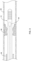
- FIG. 1 illustrates a portion of an example medical device 10.
- the medical device 10 is a blood pressure sensing guidewire 10.
- the medical device 10 may include a variety of devices including catheters, shafts, leads, wires/guidewires, or the like and/or a device designed to be used in a vascular region, body lumen, or the like.
- the medical device may include a sensor (e.g., the sensor 20) that may be utilized to measure pressure and/or temperature.
- the sensor e.g., the sensor 20
- the sensor may be used in conjunction with ultrasound, optical coherence tomography, photoacoustic imaging, or the like.
- the guidewire 10 may include a shaft or tubular member 12.
- the tubular member 12 may include a proximal region 14 and a distal region 16.
- the materials for the proximal region 14 and the distal region 16 may vary and may include those materials disclosed herein.
- the distal region 16 may include a nickel-cobalt-chromium-molybdenum alloy (e.g., MP35-N).
- the proximal region 14 may be made from the same material as the distal region 16 or a different material such as stainless steel. These are just examples. Other materials are contemplated.
- the proximal region 14 and the distal region 16 are formed from the same monolith of material.
- the proximal region 14 and the distal region 16 are portions of the same tube defining the tubular member 12.
- the proximal region 14 and the distal region 16 are separate tubular members that are joined together. For example, a section of the outer surface of the portions 14/16 may be removed and a sleeve 17 may be disposed over the removed sections to join the regions 14/16. Alternatively, the sleeve 17 may be simply disposed over the regions 14/16. Other bonds may also be used including welds, thermal bonds, adhesive bonds, or the like.
- the sleeve 17 used to join the proximal region 14 with the distal region 16 may include a material that desirably bonds with both the proximal region 14 and the distal region 16.
- the sleeve 17 may include a nickel-chromium-molybdenum alloy (e.g., INCONEL).
- a plurality of slots 18 may be formed in the tubular member 12.
- the slots 18 are formed in the distal region 16.
- the proximal region 14 lacks slots 18.
- the proximal region 14 may include slots 18.
- the slots 18 may be desirable for a number of reasons.
- the slots 18 may provide a desirable level of flexibility to the tubular member 12 (e.g., along the distal region 16) while also allowing suitable transmission of torque.
- the slots 18 may be arranged/distributed along the distal region 16 in a suitable manner.
- the slots 18 may be arranged as opposing pairs of slots 18 that are distributed along the length of the distal region 16.
- adjacent pairs of slots 18 may have a substantially constant spacing relative to one another.
- the spacing between adjacent pairs may vary.
- more distal regions of the distal region 16 may have a decreased spacing (and/or increased slot density), which may provide increased flexibility.
- more distal regions of the distal region 16 may have an increased spacing (and/or decreased slot density).
- a sensor 20, which may take the form of a pressure sensor 20, may be disposed within the tubular member 12 (e.g., within a lumen of tubular member 12). While the pressure sensor 20 is shown schematically in FIG. 1 , it can be appreciated that the structural form and/or type of the pressure sensor 20 may vary.
- the pressure sensor 20 may include a semiconductor (e.g., silicon wafer) pressure sensor, piezoelectric pressure sensor, piezo-resistive pressure sensor, capacitive pressure sensor, a fiber optic or optical pressure sensor, a Fabry-Perot type pressure sensor, an ultrasound transducer and/or ultrasound pressure sensor, a magnetic pressure sensor, a solid-state pressure sensor, or the like, or any other suitable pressure sensor.
- a semiconductor e.g., silicon wafer
- piezoelectric pressure sensor piezo-resistive pressure sensor
- capacitive pressure sensor e.g., a fiber optic or optical pressure sensor
- a Fabry-Perot type pressure sensor e.g
- the senor 20 may take the form of or otherwise be capable of being a temperature sensor, a flow sensor, an acoustic sensor, an ultrasound sensor, or the like. These types of sensors, to the extent appropriate, may be utilized in any of the devices disclosed herein.
- the pressure sensor 20 may include an optical pressure sensor.
- an optical fiber or fiber optic cable 24 (e.g., a multimode fiber optic) may be attached to the pressure sensor 20 and may extend proximally therefrom.
- the optical fiber 24 may include a central core 60 and an outer cladding 62.
- a sealing member (not shown) may attach the optical fiber 24 to the tubular member 12.
- Such an attachment member may be circumferentially disposed about and attached to the optical fiber 24 and may be secured to the inner surface of the tubular member 12 (e.g., the distal region 16).
- a centering member 26 may also be bonded to the optical fiber 24.
- the centering member 26 is proximally spaced from the pressure sensor 20. Other arrangements are contemplated such as integrating the function of the centering ring into the sensor body. The centering member 26 may help reduce forces that may be exposed to the pressure sensor 20 during navigation of guidewire and/or during use.
- the distal region 16 may include a region with a thinned wall and/or an increased inner diameter that defines a sensor housing region 52.
- the sensor housing region 52 is the region of distal region 16 that ultimately "houses" the pressure sensor 20. By virtue of having a portion of the inner wall of the tubular member 12 being removed at the sensor housing region 52, additional space may be created or otherwise defined that can accommodate the sensor 20.
- the sensor housing region 52 may include one or more openings such as one or more distal porthole openings 66 that provide fluid access to the pressure sensor 20.
- a tip member 30 may be coupled to the distal region 16.
- the tip member 30 may include a core member 32 and a spring or coil member 34.
- a distal tip 36 may be attached to the core member 32 and/or the spring 34.
- the distal tip 36 may take the form of a solder ball tip.
- the tip member 30 may be joined to the distal region 16 of the tubular member 12 with a bonding member 46 such as a weld.
- the tubular member 12 may include an outer coating 19. In some embodiments, the coating 19 may extend along substantially the full length of the tubular member 12. In other embodiments, one or more discrete sections of the tubular member 12 may include the coating 19.
- the coating 19 may be a hydrophobic coating, a hydrophilic coating, or the like.
- the tubular member 12 may also include an inner coating 64 (e.g., a hydrophobic coating, a hydrophilic coating, or the like) disposed along an inner surface thereof.
- the hydrophilic coating 64 may be disposed along the inner surface of the housing region 52.
- the core member 32 may include a coating (e.g., a hydrophilic coating).
- a proximal end region and/or a proximal end of the core member 32 may include the coating.
- the pressure sensor 20 may also include a coating (e.g., a hydrophilic coating).
- a clinician may use the guidewire 10 to measure and/or calculate FFR (e.g., the pressure after an intravascular occlusion relative to the pressure before the occlusion and/or the aortic pressure).
- Measuring and/or calculating FFR may include measuring the aortic pressure in a patient. This may include advancing guidewire the 10 through a blood vessel or body lumen 54 to a position that is proximal or upstream of an occlusion 56 as shown in FIG. 2 .
- the guidewire 10 may be advanced through a guide catheter 58 to a position where at least a portion of the sensor 20 is disposed distal of the distal end of the guide catheter 58 and measure the pressure within body lumen 54.
- This pressure may be characterized as an initial pressure.
- the aortic pressure may also be measured by another device (e.g., a pressure sensing guidewire, catheter, or the like).
- the initial pressure may be equalized with the aortic pressure.
- the initial pressure measured by the guidewire 10 may be set to be the same as the measured aortic pressure.
- the guidewire 10 may be further advanced to a position distal or downstream of the occlusion 56 as shown in FIG. 3 and the pressure within body lumen 54 may be measured. This pressure may be characterized as the downstream or distal pressure.
- the distal pressure and the aortic pressure may be used to calculate FFR.
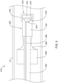
- FIG. 4 illustrates another example medical device 110 that may be similar in form and function to other medical devices disclosed herein.
- the medical device 110 may include the tubular member 12 (e.g., including the structural features described and shown herein).
- An optical fiber 124 may be disposed within the tubular member 12.
- a pressure sensor 120 may be formed at a distal end region of the optical fiber 124.
- the pressure sensor 120 may be defined by forming a depression or cavity 178 in the optical fiber 124 and then disposing a deflectable membrane 170 across the cavity 178.
- the pressure sensor 120 may include a deflectable membrane 170.
- the deflectable membrane 170 may include or otherwise be formed from a deflectable polymeric member or membrane 172.
- the use of a polymeric material for the deflectable polymeric membrane 172 may be desirable for a number of reasons.
- a deflectable polymeric membrane 172 may have an increased sensitivity relative to other membranes. Increased sensitivity may allow for higher resolution pressure measurement and/or allow for manufacturing of smaller sensors.
- a number of polymeric materials may be utilized for the deflectable polymeric membrane 172.
- the deflectable polymeric membrane 172 may include a dry film photosensitive material (such as Ordyl SY300, ADEX/SY300, or SU-8) a liquid photosensitive material such as SU-8, polyimide (e.g., a film or a liquid photosensitive material), benzocyclobutene, a variety of non-photosensitive polymer films (e.g., such as polyethylene terephthalate, cyclic olefin copolymer, KAPTON, polydimethylsiloxane, poly(methyl methacrylate), or the like).
- a dry film photosensitive material such as Ordyl SY300, ADEX/SY300, or SU-8
- a liquid photosensitive material such as SU-8
- polyimide e.g., a film or a liquid photosensitive material
- benzocyclobutene e.g., a variety of non-photosensitive polymer films (e.g., such as polyethylene terephthalate
- Some deflectable polymeric membranes 172 may have a level of permeability to fluids. It may be desirable to reduce or otherwise eliminate the permeability of the deflectable polymeric membrane 172.
- the deflectable polymeric membrane 172 may include a first or proximal coating 174, a second or distal coating 176, or both.
- one or both of the coatings 174, 176 may include a fluid-impermeable material.
- one or both of the coatings 174, 176 may include a metal such as those listed herein, a polymer such as parylene, a vapor deposited material (e.g., an oxide, nitride, carbon material, or the like), etc.
- first coating 174 and the second coating 176 are separate, distinct layers of material (including the same or different materials).
- first coating 174 and the second coating 176 may take the form of a singular structure or envelope that encapsulates or otherwise surrounds the deflectable polymeric membrane 172.
- one of the first coating 174 or the second coating 176 may include a mirror or partial mirror that may be formed by sputtering a reflective material such as chromium, silver, or the like along the deflectable polymeric membrane 172.
- a reflective material such as chromium, silver, or the like along the deflectable polymeric membrane 172.
- Other processes for forming the first coating 174, the second coating 176 or both are contemplated including evaporative coating processes.
- Other materials are contemplated including gold, copper, nickel, or the like.
- the first coating 174 may take the form of a metalized polymer film disposed on the deflectable polymer membrane 172.
- the second coating 176 may be disposed on the deflectable polymer membrane 172 after bonding the deflectable polymer membrane 172 to the optical fiber 124.
- a layer 175 forming a mirror or partial mirror may be disposed within the cavity 178 (e.g., at the end of the etched optical fiber 124).
- the first coating 174 or the second coating 176 includes a mirror (e.g., a full mirror) and the layer 175 includes a partial mirror.
- Other configurations are contemplated.
- a pressure equalization channel 180 is formed in the optical fiber 124.
- the pressure equalization channel 180 may be in fluid communication with the cavity 178 and with the deflectable membrane 170 (e.g., which may be understood to be the assembly formed by the deflectable polymeric membrane 172, the first coating 174, and the second coating 176).
- the pressure equalization channel 180 may allow for the pressure within the cavity 178 to be controlled or otherwise held more constant. This may allow the deflectable membrane 170 to be more sensitive to pressure readings within a body lumen and to make the deflectable membrane 170 to be less likely to be influenced by pressures (or vacuum) within the cavity 178. In some instances, only a single pressure equalization channel 180 may be utilized.
- the single pressure equalization channel 180 may extend down a longitudinal axis of the optical fiber 124. Alternatively, the equalization channel 180 may be offset from the longitudinal axis. In other instances, multiple pressure equalization channels 180 may be formed in the optical fiber 124. In these instances, one or more of the equalization channels 180 may extend down a longitudinal axis of the optical fiber 124. In some of these and in other instances, one or more of the equalization channels 180 may be offset from the longitudinal axis.
- FIG. 5 illustrates another example medical device 210 that may be similar in form and function to other medical devices disclosed herein.
- the medical device 210 may include the tubular member 12 (e.g., including the structural features described and shown herein).
- An optical fiber 224 may be disposed within the tubular member 12.
- a pressure sensor 220 may be coupled to a distal end region of the optical fiber 224.
- the pressure sensor 220 may include a sensor head 221 and a deflectable membrane 270.
- the deflectable membrane 270 may include a deflectable polymeric membrane 272, a first or proximal coating 274, and a second or distal coating 276.
- a cavity 278 may be formed in the pressure sensor 220 and the deflectable membrane 270 may extend across the cavity 278.
- the deflectable polymeric membrane 272, first coating 274, and second coating 276 may be similar to similarly named structures of the medical device 110.
- the second coating 276 may extend along the distal end of the deflectable polymeric membrane 272 and then extend partially along the sensor head 221.
- a layer 275 may be disposed within the cavity 278 (e.g., at the end of the etched optical fiber 224). Other configurations are contemplated.
- a pressure equalization channel (or channels) 280 may be formed in the optical fiber 224.
- the pressure equalization channel 280 may be in fluid communication with the cavity 178 and with the deflectable membrane 270.
- the pressure equalization channel 280 may allow for the pressure within the cavity 278 to be controlled or otherwise held more constant. This may allow the deflectable membrane 270 to be more sensitive to pressure readings within a body lumen and to make the deflectable membrane 270 to be less likely to be influenced by pressures (or vacuum) within the cavity 278.
- the medical device 210 may include other structural features that may be similar to those of any of the medical devices disclosed herein.
- a centering member 226 may be coupled to the optical fiber 224.
- An adhesive 282 may extend between the centering member 226 and the sensor head 221. In some instances, the adhesive 282 may be coupled to the sensor head 221. Other constructions are contemplated.
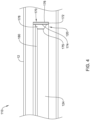
- FIG. 6 illustrates another example medical device 310 that may be similar in form and function to other medical devices disclosed herein.
- the medical device 310 may include the tubular member 12 (e.g., including the structural features described and shown herein).
- An optical fiber 324 may be disposed within the tubular member 12.
- a pressure sensor 320 may be coupled to a distal end region of the optical fiber 324.
- the pressure sensor 320 may be formed by patterned and etched layers of a dry-film resist (e.g., such as SU-8).
- the pressure sensor 320 may be formed by laser writing all the way through a wafer.
- a cavity 378 may be defined in the pressure sensor 320.
- the pressure sensor 320 may include a deflectable membrane 370.
- the deflectable membrane 370 may include or otherwise be formed from a deflectable polymeric member or membrane 372.
- a pressure equalization channel (or channels) 380 may be formed in the optical fiber 324.
- the deflectable polymeric membrane 372 may include a first or proximal coating 374, a second or distal coating 376, or both similar to similarly named structures disclosed herein.
- a layer 375 forming a mirror or partial mirror may be disposed within the cavity 378 (e.g., at the end of the etched optical fiber 324).
- a glass wafer for example having a thickness in the range of about 100-500 ⁇ m, may be laser written once or a plurality of times.
- the laser e.g., a femtosecond laser
- the laser may write about 70-99% or about 95% through the glass wafer.
- laser written holes fully through the glass wafer may be formed.
- other processes such as etching or drilling may be utilized to write through a portion or all of the glass wafer.
- the glass wafer can then be etched, for example using a suitable etching reagent such as hydrofluoric acid (HF) or potassium hydroxide (KOH).
- HF hydrofluoric acid
- KOH potassium hydroxide
- the glass wafer can then be coated by sputter or evaporative coating a partial mirror along a surface of the glass wafer.
- This may include sputter or evaporative coating a material such as zirconium dioxide, titanium dioxide or a thin film metal such as aluminum, chromium, silver, titanium, molybdenum, or the like.
- a photosensitive spacer cavity layer may be coated (e.g., spin coated) on the partial mirror.
- the photosensitive layer may include a material such as SU-8, Ordyl SY300, ADEX/SUEX, or the like.
- the spacer layer can be etched by exposure to UV.
- a dry film laminate polymer such as Ordyl SY300, polyimide, or the like may be disposed over the etched spacer layer and a full metal sputter or evaporative coat may be disposed over the dry film laminate polymer.
- a polymer layer e.g. such as polyethylene terephthalate, cyclic olefin copolymer, KAPTON, polydimethylsiloxane, poly(methyl methacrylate), or the like
- the wafer can then be used (e.g., using HF).
- a photoresist can be spun onto a dummy silicon wafer.
- the polymer side of the glass wafer can be attached to the photoresist (or alternatively to wax, UV tape, thermal tape or polyacrylic acid) and the wafer can be diced (e.g., laser or mechanically diced).
- the sensors can be secured to optical fibers by disposing an adhesive (e.g., a UV epoxy) on the fiber or the sensor and then securing the sensor to the fiber.
- the photoresist can be lifted off, cleaned, and a full mirror and/or sealing layer can be attached (e.g., via sputtering or evaporation).
- a glass wafer may be laser written (e.g., with a femtosecond laser) about 70-99% or about 95% through the glass wafer once or a plurality of times.
- the glass wafer can then be coated by sputter coating a partial mirror along a surface of the glass wafer. This may include sputter coating or evaporative coating a material such as chromium, gold, chromium-gold, or the like.
- the glass wafer can then be etched, for example using a suitable etching reagent such as HF.
- the glass wafer can then be coated by sputter coating a partial mirror along a surface of the glass wafer.
- This may include sputter coating a material such as chromium, silver, or the like.
- a photosensitive spacer cavity layer may be coated (e.g., spin coated) on the partial mirror.
- the photosensitive layer may include a material such as SU-8, Ordyl SY300, or the like. The remainder of the process may then follow the remaining step of the previously described process.
- a glass wafer may be laser written (e.g., with a femtosecond laser) about 70-99% or about 95% through the glass wafer a plurality of times.
- the glass wafer can then be etched, for example using a suitable etching reagent such as HF.
- the glass wafer can then be coated by sputter or evaporative coating a partial mirror along a surface of the glass wafer. This may include coating a material such as zirconium dioxide, titanium dioxide or a thin film metal such as aluminum, chromium, silver, or the like.
- a sacrificial layer e.g., a photoresist
- can be coated onto the glass wafer e.g., spin coated).
- the sacrificial layer can be exposed to UV to pattern and develop the sacrificial layer.
- a photosensitive spacer cavity layer may be coated (e.g., spin coated) on the partial mirror.
- the photosensitive layer may include a material such as SU-8, Ordyl SY300, or the like.
- the glass wafer can then be etched through using a suitable etching reagent such as HF.
- the sacrificial layer can then be removed through the glass holes using a suitable stripping reagent. The remainder of the process may then follow the remaining step of the previously described process.
- the materials that can be used for the various components of the guidewire 10 (and/or other guidewires disclosed herein) and the various tubular members disclosed herein may include those commonly associated with medical devices.
- the following discussion makes reference to the tubular member 12 and other components of the guidewire 10.
- this is not intended to limit the devices and methods described herein, as the discussion may be applied to other tubular members and/or components of tubular members or devices disclosed herein.
- the tubular member 12 and/or other components of the guidewire 10 may be made from a metal, metal alloy, polymer (some examples of which are disclosed below), a metal-polymer composite, ceramics, combinations thereof, and the like, or other suitable material.
- suitable polymers may include polytetrafluoroethylene (PTFE), ethylene tetrafluoroethylene (ETFE), fluorinated ethylene propylene (FEP), polyoxymethylene (POM, for example, DELRIN ® available from DuPont), polyether block ester, polyurethane (for example, Polyurethane 85A), polypropylene (PP), polyvinylchloride (PVC), polyether-ester (for example, ARNITEL ® available from DSM Engineering Plastics), ether or ester based copolymers (for example, butylene/poly(alkylene ether) phthalate and/or other polyester elastomers such as HYTREL ® available from DuPont), polyamide (for example, DU
- suitable metals and metal alloys include stainless steel, such as 304V, 304L, and 316LV stainless steel; mild steel; nickel-titanium alloy such as linear-elastic and/or super-elastic nitinol; other nickel alloys such as nickel-chromium-molybdenum alloys (e.g., UNS: N06625 such as INCONEL ® 625, UNS: N06022 such as HASTELLOY ® C-22 ® , UNS: N10276 such as HASTELLOY ® C276 ® , other HASTELLOY ® alloys, and the like), nickel-copper alloys (e.g., UNS: N04400 such as MONEL ® 400, NICKELVAC ® 400, NICORROS ® 400, and the like), nickel-cobalt-chromium-molybdenum alloys (e.g., UNS: R30035 such as MP35-N ® and the like), nickel-co
- portions or all of the guidewire 10 may also be doped with, made of, or otherwise include a radiopaque material.
- Radiopaque materials are understood to be materials capable of producing a relatively bright image on a fluoroscopy screen or another imaging technique during a medical procedure. This relatively bright image aids the user of the guidewire 10 in determining its location.
- Some examples of radiopaque materials can include, but are not limited to, gold, platinum, palladium, tantalum, tungsten alloy, polymer material loaded with a radiopaque filler, and the like. Additionally, other radiopaque marker bands and/or coils may also be incorporated into the design of the guidewire 10 to achieve the same result.
- a degree of Magnetic Resonance Imaging (MRI) compatibility is imparted into the guidewire 10.
- the guidewire 10, or portions thereof may be made of a material that does not substantially distort the image and create substantial artifacts (e.g., gaps in the image). Certain ferromagnetic materials, for example, may not be suitable because they may create artifacts in an MRI image.
- Guidewire 10, or portions thereof may also be made from a material that the MRI machine can image.
- Some materials that exhibit these characteristics include, for example, tungsten, cobalt-chromium-molybdenum alloys (e.g., UNS: R30003 such as ELGILOY ® , PHYNOX ® , and the like), nickel-cobalt-chromium-molybdenum alloys (e.g., UNS: R30035 such as MP35-N ® and the like), nitinol, and the like, and others.
- cobalt-chromium-molybdenum alloys e.g., UNS: R30003 such as ELGILOY ® , PHYNOX ® , and the like
- nickel-cobalt-chromium-molybdenum alloys e.g., UNS: R30035 such as MP35-N ® and the like
- nitinol and the like, and others.
Description
- The present disclosure pertains to medical devices, and methods for manufacturing medical devices. More particularly, the present disclosure pertains to blood pressure sensing guidewires and methods for using pressure sensing guidewires.
- A wide variety of intracorporeal medical devices have been developed for medical use, for example, intravascular use. Some of these devices include guidewires, catheters, and the like. These devices are manufactured by any one of a variety of different manufacturing methods and may be used according to any one of a variety of methods. Of the known medical devices and methods, each has certain advantages and disadvantages. There is an ongoing need to provide alternative medical devices as well as alternative methods for manufacturing and using medical devices.
-
US 5 005 584 A relates to a fiber optic transducer utilizing a flexible membrane to transduce pressure by interrupting light transmission between fiber optic paths in a catheter or guide wire carrier by misaligning the paths or by interposing a blocking opaque shutter between the paths. Further exemplary medical pressure sensing devices are shown inUS-4487206-A ,US-4711246-A ,US-2017/065225-A1 ,US-2015/032011-A1 ,US-2009/226128-A1 andUS-2012/227505-A1 . - This disclosure provides design, material, manufacturing method, and use alternatives for medical devices. A pressure sensing guidewire is disclosed. The pressure sensing guidewire comprises: a tubular member having a proximal region and a housing region; an optical pressure sensor disposed within the housing region; wherein the optical pressure sensor includes a sensor body and a deflectable membrane coupled to the sensor body; wherein the deflectable membrane includes a polymer; an optical fiber coupled to the sensor body and extending proximally therefrom; and wherein a pressure equalization channel is formed in the optical fiber, the sensor body, or both. The pressure equalization channel extends through the optical fiber.
- Alternatively or additionally to any of the embodiments above, the proximal region of the tubular member has a first inner diameter, wherein the housing region of the tubular member has a second inner diameter, and wherein the first inner diameter is different from the second inner diameter.
- Alternatively or additionally to any of the embodiments above, the first inner diameter is smaller than the second inner diameter.
- Alternatively or additionally to any of the embodiments above, the tubular member has a substantially constant outer diameter.
- Alternatively or additionally to any of the embodiments above, the optical fiber has a longitudinal axis and wherein the pressure equalization channel is radially offset from the longitudinal axis.
- Alternatively or additionally to any of the embodiments above, the deflectable membrane includes a proximal coating.
- Alternatively or additionally to any of the embodiments above, the proximal coating includes a metal.
- Alternatively or additionally to any of the embodiments above, the deflectable membrane includes a distal coating.
- Alternatively or additionally to any of the embodiments above, the distal coating includes a metal.
- Alternatively or additionally to any of the embodiments above, the deflectable membrane is encased in a fluid-impermeable coating.
- A pressure sensing medical device is disclosed. The pressure sensing medical device comprises: a tubular member having a proximal region and a housing region; an optical fiber extending at least partially through the tubular member, the optical fiber having a distal end region; a pressure sensor formed at the distal end region of the optical fiber, the pressure sensor including a deflectable membrane; wherein the deflectable membrane includes a polymer; and a pressure equalization channel extending through the optical fiber and in fluid communication with the deflectable membrane.
- Alternatively or additionally to any of the embodiments above, the proximal region of the tubular member has a first inner diameter, wherein the housing region of the tubular member has a second inner diameter, and wherein the first inner diameter is different from the second inner diameter.
- Alternatively or additionally to any of the embodiments above, the first inner diameter is smaller than the second inner diameter.
- Alternatively or additionally to any of the embodiments above, the tubular member has a substantially constant outer diameter.
- Alternatively or additionally to any of the embodiments above, the deflectable membrane includes a first coating disposed along a first side of the deflectable membrane, a second coating disposed along a second side of the deflectable membrane, or both.
- Alternatively or additionally to any of the embodiments above, the first coating includes a metal.
- Alternatively or additionally to any of the embodiments above, the first coating includes a fluid-impermeable material.
- Alternatively or additionally to any of the embodiments above, the pressure sensor includes a sensor head coupled to the optical fiber.
- A pressure sensing guidewire is disclosed. The pressure sensing guidewire comprises: a tubular member having a proximal region, a distal region, and a sensor housing region; wherein the distal region has a plurality of slots formed therein; an optical fiber extending at least partially through the tubular member, the optical fiber having a distal end region; a pressure sensor coupled to the distal end region of the optical fiber, the pressure sensor including a sensor head defining a cavity and a deflectable membrane coupled to the sensor head and extending across the cavity; wherein the deflectable membrane includes a polymer; and one or more pressure equalization channels extending through the optical fiber and in fluid communication with the cavity and with the deflectable membrane.
- The above summary of some embodiments is not intended to describe each disclosed embodiment or every implementation of the present disclosure. The Figures, and Detailed Description, which follow, more particularly exemplify these embodiments.
- The disclosure may be more completely understood in consideration of the following detailed description in connection with the accompanying drawings, in which:
-
FIG. 1 is a partial cross-sectional side view of a portion of an example medical device. -
FIG. 2 is a partial cross-sectional view of an example medical device disposed at a first position adjacent to an intravascular occlusion. -
FIG. 3 is a partial cross-sectional view of an example medical device disposed at a second position adjacent to an intravascular occlusion. -
FIG. 4 illustrates a portion of an example medical device. -
FIG. 5 illustrates a portion of an example medical device. -
FIG. 6 illustrates a portion of an example medical device. - While the disclosure is amenable to various modifications and alternative forms, specifics thereof have been shown by way of example in the drawings and will be described in detail.
- For the following defined terms, these definitions shall be applied, unless a different definition is given in the claims or elsewhere in this specification.
- All numeric values are herein assumed to be modified by the term "about", whether or not explicitly indicated. The term "about" generally refers to a range of numbers that one of skill in the art would consider equivalent to the recited value (e.g., having the same function or result). In many instances, the terms "about" may include numbers that are rounded to the nearest significant figure.
- The recitation of numerical ranges by endpoints includes all numbers within that range (e.g. 1 to 5 includes 1, 1.5, 2, 2.75, 3, 3.80, 4, and 5).
- As used in this specification and the appended claims, the singular forms "a", "an", and "the" include plural referents unless the content clearly dictates otherwise. As used in this specification and the appended claims, the term "or" is generally employed in its sense including "and/or" unless the content clearly dictates otherwise.
- It is noted that references in the specification to "an embodiment", "some embodiments", "other embodiments", etc., indicate that the embodiment described may include one or more particular features, structures, and/or characteristics. However, such recitations do not necessarily mean that all embodiments include the particular features, structures, and/or characteristics. Additionally, when particular features, structures, and/or characteristics are described in connection with one embodiment, it should be understood that such features, structures, and/or characteristics may also be used connection with other embodiments whether or not explicitly described unless clearly stated to the contrary.
- The following detailed description should be read with reference to the drawings in which similar elements in different drawings are numbered the same. The drawings, which are not necessarily to scale, depict illustrative embodiments and are not intended to limit the scope of the invention.
- During some medical interventions, it may be desirable to measure and/or monitor the blood pressure within a blood vessel. For example, some medical devices may include pressure sensors that allow a clinician to monitor blood pressure. Such devices may be useful in determining fractional flow reserve (FFR), which may be understood as the pressure after a stenosis relative to the pressure before the stenosis (and/or the aortic pressure).
-
FIG. 1 illustrates a portion of an examplemedical device 10. In this example, themedical device 10 is a bloodpressure sensing guidewire 10. However, this is not intended to be limiting as other medical devices are contemplated. For example, themedical device 10 may include a variety of devices including catheters, shafts, leads, wires/guidewires, or the like and/or a device designed to be used in a vascular region, body lumen, or the like. As discussed herein, the medical device may include a sensor (e.g., the sensor 20) that may be utilized to measure pressure and/or temperature. In some of these and in other instances, the sensor (e.g., the sensor 20) may be used in conjunction with ultrasound, optical coherence tomography, photoacoustic imaging, or the like. - The
guidewire 10 may include a shaft ortubular member 12. Thetubular member 12 may include aproximal region 14 and adistal region 16. The materials for theproximal region 14 and thedistal region 16 may vary and may include those materials disclosed herein. For example, thedistal region 16 may include a nickel-cobalt-chromium-molybdenum alloy (e.g., MP35-N). Theproximal region 14 may be made from the same material as thedistal region 16 or a different material such as stainless steel. These are just examples. Other materials are contemplated. - In some embodiments, the
proximal region 14 and thedistal region 16 are formed from the same monolith of material. In other words, theproximal region 14 and thedistal region 16 are portions of the same tube defining thetubular member 12. In other embodiments, theproximal region 14 and thedistal region 16 are separate tubular members that are joined together. For example, a section of the outer surface of theportions 14/16 may be removed and asleeve 17 may be disposed over the removed sections to join theregions 14/16. Alternatively, thesleeve 17 may be simply disposed over theregions 14/16. Other bonds may also be used including welds, thermal bonds, adhesive bonds, or the like. If utilized, thesleeve 17 used to join theproximal region 14 with thedistal region 16 may include a material that desirably bonds with both theproximal region 14 and thedistal region 16. For example, thesleeve 17 may include a nickel-chromium-molybdenum alloy (e.g., INCONEL). - A plurality of
slots 18 may be formed in thetubular member 12. In at least some embodiments, theslots 18 are formed in thedistal region 16. In at least some embodiments, theproximal region 14 lacksslots 18. However, theproximal region 14 may includeslots 18. Theslots 18 may be desirable for a number of reasons. For example, theslots 18 may provide a desirable level of flexibility to the tubular member 12 (e.g., along the distal region 16) while also allowing suitable transmission of torque. Theslots 18 may be arranged/distributed along thedistal region 16 in a suitable manner. For example, theslots 18 may be arranged as opposing pairs ofslots 18 that are distributed along the length of thedistal region 16. In some embodiments, adjacent pairs ofslots 18 may have a substantially constant spacing relative to one another. Alternatively, the spacing between adjacent pairs may vary. For example, more distal regions of thedistal region 16 may have a decreased spacing (and/or increased slot density), which may provide increased flexibility. In other embodiments, more distal regions of thedistal region 16 may have an increased spacing (and/or decreased slot density). These are just examples. Other arrangements are contemplated. - A
sensor 20, which may take the form of apressure sensor 20, may be disposed within the tubular member 12 (e.g., within a lumen of tubular member 12). While thepressure sensor 20 is shown schematically inFIG. 1 , it can be appreciated that the structural form and/or type of thepressure sensor 20 may vary. For example, thepressure sensor 20 may include a semiconductor (e.g., silicon wafer) pressure sensor, piezoelectric pressure sensor, piezo-resistive pressure sensor, capacitive pressure sensor, a fiber optic or optical pressure sensor, a Fabry-Perot type pressure sensor, an ultrasound transducer and/or ultrasound pressure sensor, a magnetic pressure sensor, a solid-state pressure sensor, or the like, or any other suitable pressure sensor. In some of these and in other instances, thesensor 20 may take the form of or otherwise be capable of being a temperature sensor, a flow sensor, an acoustic sensor, an ultrasound sensor, or the like. These types of sensors, to the extent appropriate, may be utilized in any of the devices disclosed herein. - As indicated above, the
pressure sensor 20 may include an optical pressure sensor. In at least some of these embodiments, an optical fiber or fiber optic cable 24 (e.g., a multimode fiber optic) may be attached to thepressure sensor 20 and may extend proximally therefrom. Theoptical fiber 24 may include acentral core 60 and anouter cladding 62. In some instances, a sealing member (not shown) may attach theoptical fiber 24 to thetubular member 12. Such an attachment member may be circumferentially disposed about and attached to theoptical fiber 24 and may be secured to the inner surface of the tubular member 12 (e.g., the distal region 16). In addition, a centeringmember 26 may also be bonded to theoptical fiber 24. In at least some embodiments, the centeringmember 26 is proximally spaced from thepressure sensor 20. Other arrangements are contemplated such as integrating the function of the centering ring into the sensor body. The centeringmember 26 may help reduce forces that may be exposed to thepressure sensor 20 during navigation of guidewire and/or during use. - In at least some embodiments, the
distal region 16 may include a region with a thinned wall and/or an increased inner diameter that defines asensor housing region 52. In general, thesensor housing region 52 is the region ofdistal region 16 that ultimately "houses" thepressure sensor 20. By virtue of having a portion of the inner wall of thetubular member 12 being removed at thesensor housing region 52, additional space may be created or otherwise defined that can accommodate thesensor 20. Thesensor housing region 52 may include one or more openings such as one or moredistal porthole openings 66 that provide fluid access to thepressure sensor 20. - A
tip member 30 may be coupled to thedistal region 16. Thetip member 30 may include acore member 32 and a spring orcoil member 34. Adistal tip 36 may be attached to thecore member 32 and/or thespring 34. In at least some embodiments, thedistal tip 36 may take the form of a solder ball tip. Thetip member 30 may be joined to thedistal region 16 of thetubular member 12 with a bonding member 46 such as a weld. - The
tubular member 12 may include anouter coating 19. In some embodiments, thecoating 19 may extend along substantially the full length of thetubular member 12. In other embodiments, one or more discrete sections of thetubular member 12 may include thecoating 19. Thecoating 19 may be a hydrophobic coating, a hydrophilic coating, or the like. Thetubular member 12 may also include an inner coating 64 (e.g., a hydrophobic coating, a hydrophilic coating, or the like) disposed along an inner surface thereof. For example, thehydrophilic coating 64 may be disposed along the inner surface of thehousing region 52. In some of these and in other instances, thecore member 32 may include a coating (e.g., a hydrophilic coating). For example, a proximal end region and/or a proximal end of thecore member 32 may include the coating. In some of these and in other instances, thepressure sensor 20 may also include a coating (e.g., a hydrophilic coating). - In use, a clinician may use the
guidewire 10 to measure and/or calculate FFR (e.g., the pressure after an intravascular occlusion relative to the pressure before the occlusion and/or the aortic pressure). Measuring and/or calculating FFR may include measuring the aortic pressure in a patient. This may include advancing guidewire the 10 through a blood vessel orbody lumen 54 to a position that is proximal or upstream of anocclusion 56 as shown inFIG. 2 . For example, theguidewire 10 may be advanced through aguide catheter 58 to a position where at least a portion of thesensor 20 is disposed distal of the distal end of theguide catheter 58 and measure the pressure withinbody lumen 54. This pressure may be characterized as an initial pressure. In some embodiments, the aortic pressure may also be measured by another device (e.g., a pressure sensing guidewire, catheter, or the like). The initial pressure may be equalized with the aortic pressure. For example, the initial pressure measured by theguidewire 10 may be set to be the same as the measured aortic pressure. Theguidewire 10 may be further advanced to a position distal or downstream of theocclusion 56 as shown inFIG. 3 and the pressure withinbody lumen 54 may be measured. This pressure may be characterized as the downstream or distal pressure. The distal pressure and the aortic pressure may be used to calculate FFR. -
FIG. 4 illustrates another examplemedical device 110 that may be similar in form and function to other medical devices disclosed herein. Themedical device 110 may include the tubular member 12 (e.g., including the structural features described and shown herein). An optical fiber 124 may be disposed within thetubular member 12. Apressure sensor 120 may be formed at a distal end region of the optical fiber 124. In this example, thepressure sensor 120 may be defined by forming a depression orcavity 178 in the optical fiber 124 and then disposing adeflectable membrane 170 across thecavity 178. - As indicated above, the
pressure sensor 120 may include adeflectable membrane 170. In this example, thedeflectable membrane 170 may include or otherwise be formed from a deflectable polymeric member ormembrane 172. The use of a polymeric material for the deflectablepolymeric membrane 172 may be desirable for a number of reasons. For example, a deflectablepolymeric membrane 172 may have an increased sensitivity relative to other membranes. Increased sensitivity may allow for higher resolution pressure measurement and/or allow for manufacturing of smaller sensors. A number of polymeric materials may be utilized for the deflectablepolymeric membrane 172. For example, the deflectablepolymeric membrane 172 may include a dry film photosensitive material (such as Ordyl SY300, ADEX/SY300, or SU-8) a liquid photosensitive material such as SU-8, polyimide (e.g., a film or a liquid photosensitive material), benzocyclobutene, a variety of non-photosensitive polymer films (e.g., such as polyethylene terephthalate, cyclic olefin copolymer, KAPTON, polydimethylsiloxane, poly(methyl methacrylate), or the like). - Some deflectable
polymeric membranes 172 may have a level of permeability to fluids. It may be desirable to reduce or otherwise eliminate the permeability of the deflectablepolymeric membrane 172. For example, the deflectablepolymeric membrane 172 may include a first orproximal coating 174, a second ordistal coating 176, or both. In some instances, one or both of thecoatings coatings first coating 174 and thesecond coating 176 are separate, distinct layers of material (including the same or different materials). Alternatively, thefirst coating 174 and thesecond coating 176 may take the form of a singular structure or envelope that encapsulates or otherwise surrounds the deflectablepolymeric membrane 172. - In some instances, one of the
first coating 174 or thesecond coating 176 may include a mirror or partial mirror that may be formed by sputtering a reflective material such as chromium, silver, or the like along the deflectablepolymeric membrane 172. Other processes for forming thefirst coating 174, thesecond coating 176 or both are contemplated including evaporative coating processes. Other materials are contemplated including gold, copper, nickel, or the like. In some instances, if thefirst coating 174 includes a mirror or partial mirror, thefirst coating 174 may take the form of a metalized polymer film disposed on thedeflectable polymer membrane 172. If thesecond coating 176 includes a mirror or partial mirror, thesecond coating 176 may be disposed on thedeflectable polymer membrane 172 after bonding thedeflectable polymer membrane 172 to the optical fiber 124. In some of these and in other instances, alayer 175 forming a mirror or partial mirror may be disposed within the cavity 178 (e.g., at the end of the etched optical fiber 124). In one instance, thefirst coating 174 or thesecond coating 176 includes a mirror (e.g., a full mirror) and thelayer 175 includes a partial mirror. Other configurations are contemplated. - According to the invention a
pressure equalization channel 180 is formed in the optical fiber 124. Thepressure equalization channel 180 may be in fluid communication with thecavity 178 and with the deflectable membrane 170 (e.g., which may be understood to be the assembly formed by the deflectablepolymeric membrane 172, thefirst coating 174, and the second coating 176). Thepressure equalization channel 180 may allow for the pressure within thecavity 178 to be controlled or otherwise held more constant. This may allow thedeflectable membrane 170 to be more sensitive to pressure readings within a body lumen and to make thedeflectable membrane 170 to be less likely to be influenced by pressures (or vacuum) within thecavity 178. In some instances, only a singlepressure equalization channel 180 may be utilized. The singlepressure equalization channel 180 may extend down a longitudinal axis of the optical fiber 124. Alternatively, theequalization channel 180 may be offset from the longitudinal axis. In other instances, multiplepressure equalization channels 180 may be formed in the optical fiber 124. In these instances, one or more of theequalization channels 180 may extend down a longitudinal axis of the optical fiber 124. In some of these and in other instances, one or more of theequalization channels 180 may be offset from the longitudinal axis. -
FIG. 5 illustrates another examplemedical device 210 that may be similar in form and function to other medical devices disclosed herein. Themedical device 210 may include the tubular member 12 (e.g., including the structural features described and shown herein). Anoptical fiber 224 may be disposed within thetubular member 12. Apressure sensor 220 may be coupled to a distal end region of theoptical fiber 224. Thepressure sensor 220 may include asensor head 221 and adeflectable membrane 270. Thedeflectable membrane 270 may include a deflectablepolymeric membrane 272, a first orproximal coating 274, and a second ordistal coating 276. Acavity 278 may be formed in thepressure sensor 220 and thedeflectable membrane 270 may extend across thecavity 278. The deflectablepolymeric membrane 272,first coating 274, andsecond coating 276 may be similar to similarly named structures of themedical device 110. In some instances, thesecond coating 276 may extend along the distal end of the deflectablepolymeric membrane 272 and then extend partially along thesensor head 221. In some instances, alayer 275 may be disposed within the cavity 278 (e.g., at the end of the etched optical fiber 224). Other configurations are contemplated. - A pressure equalization channel (or channels) 280 may be formed in the
optical fiber 224. Thepressure equalization channel 280 may be in fluid communication with thecavity 178 and with thedeflectable membrane 270. Thepressure equalization channel 280 may allow for the pressure within thecavity 278 to be controlled or otherwise held more constant. This may allow thedeflectable membrane 270 to be more sensitive to pressure readings within a body lumen and to make thedeflectable membrane 270 to be less likely to be influenced by pressures (or vacuum) within thecavity 278. - The
medical device 210 may include other structural features that may be similar to those of any of the medical devices disclosed herein. For example, a centeringmember 226 may be coupled to theoptical fiber 224. An adhesive 282 may extend between the centeringmember 226 and thesensor head 221. In some instances, the adhesive 282 may be coupled to thesensor head 221. Other constructions are contemplated. -
FIG. 6 illustrates another examplemedical device 310 that may be similar in form and function to other medical devices disclosed herein. Themedical device 310 may include the tubular member 12 (e.g., including the structural features described and shown herein). Anoptical fiber 324 may be disposed within thetubular member 12. Apressure sensor 320 may be coupled to a distal end region of theoptical fiber 324. In this example, thepressure sensor 320 may be formed by patterned and etched layers of a dry-film resist (e.g., such as SU-8). For example, thepressure sensor 320 may be formed by laser writing all the way through a wafer. Acavity 378 may be defined in thepressure sensor 320. - The
pressure sensor 320 may include adeflectable membrane 370. In this example, thedeflectable membrane 370 may include or otherwise be formed from a deflectable polymeric member ormembrane 372. A pressure equalization channel (or channels) 380 may be formed in theoptical fiber 324. In some instances, the deflectablepolymeric membrane 372 may include a first orproximal coating 374, a second ordistal coating 376, or both similar to similarly named structures disclosed herein. In some of these and in other instances, alayer 375 forming a mirror or partial mirror may be disposed within the cavity 378 (e.g., at the end of the etched optical fiber 324). - A number of processes for fabricating pressure sensors are also contemplated. In one example fabrication process, a glass wafer, for example having a thickness in the range of about 100-500 µm, may be laser written once or a plurality of times. The laser (e.g., a femtosecond laser) may write about 70-99% or about 95% through the glass wafer. In other instances, laser written holes fully through the glass wafer may be formed. In alternative instances, other processes such as etching or drilling may be utilized to write through a portion or all of the glass wafer. The glass wafer can then be etched, for example using a suitable etching reagent such as hydrofluoric acid (HF) or potassium hydroxide (KOH). The glass wafer can then be coated by sputter or evaporative coating a partial mirror along a surface of the glass wafer. This may include sputter or evaporative coating a material such as zirconium dioxide, titanium dioxide or a thin film metal such as aluminum, chromium, silver, titanium, molybdenum, or the like. A photosensitive spacer cavity layer may be coated (e.g., spin coated) on the partial mirror. The photosensitive layer may include a material such as SU-8, Ordyl SY300, ADEX/SUEX, or the like. The spacer layer can be etched by exposure to UV. In some instances, a dry film laminate polymer such as Ordyl SY300, polyimide, or the like may be disposed over the etched spacer layer and a full metal sputter or evaporative coat may be disposed over the dry film laminate polymer. In other instances, a polymer layer (e.g. such as polyethylene terephthalate, cyclic olefin copolymer, KAPTON, polydimethylsiloxane, poly(methyl methacrylate), or the like) with or without a metal coating may be disposed over the etched spacer layer and then baked. The wafer can then be used (e.g., using HF). A photoresist can be spun onto a dummy silicon wafer. The polymer side of the glass wafer can be attached to the photoresist (or alternatively to wax, UV tape, thermal tape or polyacrylic acid) and the wafer can be diced (e.g., laser or mechanically diced). Once diced into photo sensors, the sensors can be secured to optical fibers by disposing an adhesive (e.g., a UV epoxy) on the fiber or the sensor and then securing the sensor to the fiber. The photoresist can be lifted off, cleaned, and a full mirror and/or sealing layer can be attached (e.g., via sputtering or evaporation).
- In another example process, a glass wafer may be laser written (e.g., with a femtosecond laser) about 70-99% or about 95% through the glass wafer once or a plurality of times. The glass wafer can then be coated by sputter coating a partial mirror along a surface of the glass wafer. This may include sputter coating or evaporative coating a material such as chromium, gold, chromium-gold, or the like. The glass wafer can then be etched, for example using a suitable etching reagent such as HF. The glass wafer can then be coated by sputter coating a partial mirror along a surface of the glass wafer. This may include sputter coating a material such as chromium, silver, or the like. A photosensitive spacer cavity layer may be coated (e.g., spin coated) on the partial mirror. The photosensitive layer may include a material such as SU-8, Ordyl SY300, or the like. The remainder of the process may then follow the remaining step of the previously described process.
- In another example process, a glass wafer may be laser written (e.g., with a femtosecond laser) about 70-99% or about 95% through the glass wafer a plurality of times. The glass wafer can then be etched, for example using a suitable etching reagent such as HF. The glass wafer can then be coated by sputter or evaporative coating a partial mirror along a surface of the glass wafer. This may include coating a material such as zirconium dioxide, titanium dioxide or a thin film metal such as aluminum, chromium, silver, or the like. A sacrificial layer (e.g., a photoresist) can be coated onto the glass wafer (e.g., spin coated). The sacrificial layer can be exposed to UV to pattern and develop the sacrificial layer. A photosensitive spacer cavity layer may be coated (e.g., spin coated) on the partial mirror. The photosensitive layer may include a material such as SU-8, Ordyl SY300, or the like. The glass wafer can then be etched through using a suitable etching reagent such as HF. The sacrificial layer can then be removed through the glass holes using a suitable stripping reagent. The remainder of the process may then follow the remaining step of the previously described process.
- The materials that can be used for the various components of the guidewire 10 (and/or other guidewires disclosed herein) and the various tubular members disclosed herein may include those commonly associated with medical devices. For simplicity purposes, the following discussion makes reference to the
tubular member 12 and other components of theguidewire 10. However, this is not intended to limit the devices and methods described herein, as the discussion may be applied to other tubular members and/or components of tubular members or devices disclosed herein. - The
tubular member 12 and/or other components of theguidewire 10 may be made from a metal, metal alloy, polymer (some examples of which are disclosed below), a metal-polymer composite, ceramics, combinations thereof, and the like, or other suitable material. Some examples of suitable polymers may include polytetrafluoroethylene (PTFE), ethylene tetrafluoroethylene (ETFE), fluorinated ethylene propylene (FEP), polyoxymethylene (POM, for example, DELRIN® available from DuPont), polyether block ester, polyurethane (for example, Polyurethane 85A), polypropylene (PP), polyvinylchloride (PVC), polyether-ester (for example, ARNITEL® available from DSM Engineering Plastics), ether or ester based copolymers (for example, butylene/poly(alkylene ether) phthalate and/or other polyester elastomers such as HYTREL® available from DuPont), polyamide (for example, DURETHAN® available from Bayer or CRISTAMID® available from Elf Atochem), elastomeric polyamides, block polyamide/ethers, polyether block amide (PEBA, for example available under the trade name PEBAX®), ethylene vinyl acetate copolymers (EVA), silicones, polyethylene (PE), Marlex high-density polyethylene, Marlex low-density polyethylene, linear low density polyethylene (for example REXELL®), polyester, polybutylene terephthalate (PBT), polyethylene terephthalate (PET), polytrimethylene terephthalate, polyethylene naphthalate (PEN), polyetheretherketone (PEEK), polyimide (PI), polyetherimide (PEI), polyphenylene sulfide (PPS), polyphenylene oxide (PPO), poly paraphenylene terephthalamide (for example, KEVLAR®), polysulfone, nylon, nylon-12 (such as GRILAMID® available from EMS American Grilon), perfluoro(propyl vinyl ether) (PFA), ethylene vinyl alcohol, polyolefin, polystyrene, epoxy, polyvinylidene chloride (PVdC), poly(styrene-b-isobutylene-b-styrene) (for example, SIBS and/or SIBS 50A), polycarbonates, ionomers, biocompatible polymers, other suitable materials, or mixtures, combinations, copolymers thereof, polymer/metal composites, and the like. In some embodiments the sheath can be blended with a liquid crystal polymer (LCP). For example, the mixture can contain up to about 6 percent LCP. - Some examples of suitable metals and metal alloys include stainless steel, such as 304V, 304L, and 316LV stainless steel; mild steel; nickel-titanium alloy such as linear-elastic and/or super-elastic nitinol; other nickel alloys such as nickel-chromium-molybdenum alloys (e.g., UNS: N06625 such as INCONEL® 625, UNS: N06022 such as HASTELLOY® C-22®, UNS: N10276 such as HASTELLOY® C276®, other HASTELLOY® alloys, and the like), nickel-copper alloys (e.g., UNS: N04400 such as MONEL® 400, NICKELVAC® 400, NICORROS® 400, and the like), nickel-cobalt-chromium-molybdenum alloys (e.g., UNS: R30035 such as MP35-N® and the like), nickel-molybdenum alloys (e.g., UNS: N10665 such as HASTELLOY® ALLOY B2®), other nickel-chromium alloys, other nickel-molybdenum alloys, other nickel-cobalt alloys, other nickel-iron alloys, other nickel-copper alloys, other nickel-tungsten or tungsten alloys, and the like; cobalt-chromium alloys; cobalt-chromium-molybdenum alloys (e.g., UNS: R30003 such as ELGILOY®, PHYNOX®, and the like); platinum enriched stainless steel; titanium; combinations thereof; and the like; or any other suitable material.
- In at least some embodiments, portions or all of the
guidewire 10 may also be doped with, made of, or otherwise include a radiopaque material. Radiopaque materials are understood to be materials capable of producing a relatively bright image on a fluoroscopy screen or another imaging technique during a medical procedure. This relatively bright image aids the user of theguidewire 10 in determining its location. Some examples of radiopaque materials can include, but are not limited to, gold, platinum, palladium, tantalum, tungsten alloy, polymer material loaded with a radiopaque filler, and the like. Additionally, other radiopaque marker bands and/or coils may also be incorporated into the design of theguidewire 10 to achieve the same result. - In some embodiments, a degree of Magnetic Resonance Imaging (MRI) compatibility is imparted into the
guidewire 10. For example, theguidewire 10, or portions thereof, may be made of a material that does not substantially distort the image and create substantial artifacts (e.g., gaps in the image). Certain ferromagnetic materials, for example, may not be suitable because they may create artifacts in an MRI image.Guidewire 10, or portions thereof, may also be made from a material that the MRI machine can image. Some materials that exhibit these characteristics include, for example, tungsten, cobalt-chromium-molybdenum alloys (e.g., UNS: R30003 such as ELGILOY®, PHYNOX®, and the like), nickel-cobalt-chromium-molybdenum alloys (e.g., UNS: R30035 such as MP35-N® and the like), nitinol, and the like, and others. - It should be understood that this disclosure is, in many respects, only illustrative. Changes may be made in details, particularly in matters of shape, size, and arrangement of steps without exceeding the scope of the disclosure. This may include, to the extent that it is appropriate, the use of any of the features of one example embodiment being used in other embodiments. The invention's scope is, of course, defined in the language in which the appended claims are expressed.
Claims (12)
- A pressure sensing guidewire (10), comprising:a tubular member (12) having a proximal region (14) and a housing region (52);an optical pressure sensor (20; 120; 220; 320) disposed within the housing region (52);wherein the optical pressure sensor (20; 120; 220; 320) includes a sensor body and a deflectable membrane (170; 270; 370) coupled to the sensor body;wherein the deflectable membrane (170; 270; 370) includes a polymer (172; 272; 372);an optical fiber (24; 124; 224; 324) coupled to the sensor body and extending proximally therefrom; andwherein a pressure equalization channel (180; 280; 380) is formed in the optical fiber (24; 124; 224; 324), the sensor body, or both;characterized in that
the pressure equalization channel (180; 280; 380) extends through the optical fiber (24; 124; 224; 324). - The pressure sensing guidewire (10) of claim 1, wherein the proximal region (14) of the tubular member (12) has a first inner diameter, wherein the housing region (52) of the tubular member (12) has a second inner diameter, and wherein the first inner diameter is different from the second inner diameter.
- The pressure sensing guidewire (10) of claim 2, wherein the first inner diameter is smaller than the second inner diameter.
- The pressure sensing guidewire (10) of claim 3, wherein the tubular member (12) has a substantially constant outer diameter.
- The pressure sensing guidewire (10) of claim 4, wherein the optical fiber (24; 124; 224; 324) has a longitudinal axis and wherein the pressure equalization channel (180; 280; 380) is radially offset from the longitudinal axis.
- The pressure sensing guidewire (10) of any one of claims 1-5, wherein the deflectable membrane (170; 270; 370) includes a proximal coating (174; 274; 374).
- The pressure sensing guidewire (10) of claim 6, wherein the proximal coating (174; 274; 374) includes a metal.
- The pressure sensing guidewire (10) of any one of claims 1-7, wherein the deflectable membrane (170; 270; 370) includes a distal coating (176; 276; 376).
- The pressure sensing guidewire (10) of claim 8, wherein the distal coating (176; 276; 376) includes a metal.
- The pressure sensing guidewire (10) of any one of claims 1-9, wherein the deflectable membrane (170; 270; 370) is encased in a fluid-impermeable coating.
- The pressure sensing guidewire (10) of any one of claims 1-10, wherein the optical fiber (24; 124; 224; 324) extends at least partially through the tubular member (12), the optical fiber (24; 124; 224; 324) having a distal end region; wherein the pressure sensor (120; 320) is formed at the distal end region of the optical fiber (24; 124; 224; 324); and wherein the pressure equalization channel (180; 280; 380) is in fluid communication with the deflectable membrane (170; 270; 370).
- The pressure sensing guidewire (10) of claim 10, wherein the deflectable membrane (170; 270; 370) includes a first coating (174; 274; 374) disposed along a first side of the deflectable membrane (170; 270; 370), a second coating (176; 276; 376) disposed along a second side of the deflectable membrane (170; 270; 370), or both.
Applications Claiming Priority (2)
| Application Number | Priority Date | Filing Date | Title |
|---|---|---|---|
| US201862647169P | 2018-03-23 | 2018-03-23 | |
| PCT/US2019/023488 WO2019183432A1 (en) | 2018-03-23 | 2019-03-21 | Medical device with pressure sensor |
Publications (2)
| Publication Number | Publication Date |
|---|---|
| EP3768156A1 EP3768156A1 (en) | 2021-01-27 |
| EP3768156B1 true EP3768156B1 (en) | 2023-09-20 |
Family
ID=66041734
Family Applications (1)
| Application Number | Title | Priority Date | Filing Date |
|---|---|---|---|
| EP19715710.0A Active EP3768156B1 (en) | 2018-03-23 | 2019-03-21 | Medical device with pressure sensor |
Country Status (3)
| Country | Link |
|---|---|
| US (2) | US11850073B2 (en) |
| EP (1) | EP3768156B1 (en) |
| WO (1) | WO2019183432A1 (en) |
Families Citing this family (2)
| Publication number | Priority date | Publication date | Assignee | Title |
|---|---|---|---|---|
| US11850073B2 (en) * | 2018-03-23 | 2023-12-26 | Boston Scientific Scimed, Inc. | Medical device with pressure sensor |
| EP3897339A1 (en) * | 2018-12-20 | 2021-10-27 | Boston Scientific Scimed, Inc. | Endoscope system with a shaft including a sensor |
Family Cites Families (242)
| Publication number | Priority date | Publication date | Assignee | Title |
|---|---|---|---|---|
| US3273447A (en) | 1963-08-26 | 1966-09-20 | Franklin Institute | Detection and measurement device having a small flexible fiber transmission line |
| US3686958A (en) * | 1971-02-22 | 1972-08-29 | Ladd Res Ind | Fiber optic pressure detector |
| GB1440761A (en) | 1972-09-08 | 1976-06-23 | Nat Res Dev | Pressure transducer |
| US3963323A (en) | 1974-12-23 | 1976-06-15 | International Telephone And Telegraph Corporation | Fiber optic connector with protective cable sleeves |
| US4112941A (en) | 1977-01-06 | 1978-09-12 | Minnesota Mining And Manufacturing Company | Electrode and magnetic connector assembly |
| JPS53141644A (en) | 1977-05-17 | 1978-12-09 | Fujitsu Ltd | Optical connector |
| US4210029A (en) * | 1979-05-04 | 1980-07-01 | Lad Research Industries, Inc. | Differential fiber optic differential pressure sensor |
| DE3382085D1 (en) * | 1982-07-31 | 1991-02-07 | Sumitomo Electric Industries | LIGHT GUIDE. |
| US4487206A (en) | 1982-10-13 | 1984-12-11 | Honeywell Inc. | Fiber optic pressure sensor with temperature compensation and reference |
| US5178153A (en) * | 1984-03-08 | 1993-01-12 | Einzig Robert E | Fluid flow sensing apparatus for in vivo and industrial applications employing novel differential optical fiber pressure sensors |
| US4893630A (en) | 1984-04-06 | 1990-01-16 | Trinity Computing Systems, Inc. | Apparatus and method for analyzing physiological conditions within an organ of a living body |
| GB8603672D0 (en) | 1986-02-14 | 1986-03-19 | British Telecomm | Reducing splice loss between dissimilar fibres |
| US4727730A (en) * | 1986-07-10 | 1988-03-01 | Medex, Inc. | Integrated optic system for monitoring blood pressure |
| GB2193310A (en) * | 1986-08-01 | 1988-02-03 | Boc Group Plc | Pressure sensor |
| SE454045B (en) * | 1986-08-04 | 1988-03-28 | Radisensor Ab | LEADER FOR MECHANICAL CONTROL OF A CATHETIC DURING HEART AND KERL SURGERY |
| US4711246A (en) | 1986-09-02 | 1987-12-08 | Fiberoptic Sensor Technologies, Inc. | Fiber optic coupled pressure transducer using single fiber and method of fabrication |
| US4757194A (en) * | 1986-10-10 | 1988-07-12 | Oxbridge, Inc. | Methods and apparatus for sensing the mechanical application of force |
| US4771782A (en) | 1986-11-14 | 1988-09-20 | Millar Instruments, Inc. | Method and assembly for introducing multiple catheters into a biological vessel |
| US5005584A (en) * | 1987-06-15 | 1991-04-09 | Mnm Enterprises, Inc. | Fiber optic pressure transducer |
| US4787396A (en) * | 1987-06-18 | 1988-11-29 | Fiberoptic Sensor Technologies, Inc. | Fiberoptic pressure transducer |
| US4953553A (en) | 1989-05-11 | 1990-09-04 | Advanced Cardiovascular Systems, Inc. | Pressure monitoring guidewire with a flexible distal portion |
| CA1321089C (en) | 1988-05-06 | 1993-08-10 | Adc Telecommunications, Inc. | Optical switch |
| US5178159A (en) | 1988-11-02 | 1993-01-12 | Cardiometrics, Inc. | Torqueable guide wire assembly with electrical functions, male and female connectors rotatable with respect to one another |
| US4924870A (en) * | 1989-01-13 | 1990-05-15 | Fiberoptic Sensor Technologies, Inc. | Fiber optic sensors |
| US5779698A (en) | 1989-01-18 | 1998-07-14 | Applied Medical Resources Corporation | Angioplasty catheter system and method for making same |
| US5313957A (en) | 1990-01-05 | 1994-05-24 | Medamicus, Inc. | Guide wire mounted pressure transducer |
| US5238004A (en) | 1990-04-10 | 1993-08-24 | Boston Scientific Corporation | High elongation linear elastic guidewire |
| US5135503A (en) | 1990-05-16 | 1992-08-04 | Advanced Cardiovascular Systems, Inc. | Shaping ribbon for guiding members |
| US5106455A (en) | 1991-01-28 | 1992-04-21 | Sarcos Group | Method and apparatus for fabrication of micro-structures using non-planar, exposure beam lithography |
| AU660444B2 (en) | 1991-02-15 | 1995-06-29 | Ingemar H. Lundquist | Torquable catheter and method |
| CA2117088A1 (en) | 1991-09-05 | 1993-03-18 | David R. Holmes | Flexible tubular device for use in medical applications |
| US5280786A (en) | 1992-01-21 | 1994-01-25 | Fiberoptic Sensor Technologies, Inc. | Fiberoptic blood pressure and oxygenation sensor |
| US5280173A (en) * | 1992-01-31 | 1994-01-18 | Brown University Research Foundation | Electric and electromagnetic field sensing system including an optical transducer |
| US5437288A (en) | 1992-09-04 | 1995-08-01 | Mayo Foundation For Medical Education And Research | Flexible catheter guidewire |
| US5425371A (en) | 1992-10-05 | 1995-06-20 | Metatech Corporation | Fiberoptic pressure transducer |
| US5414507A (en) | 1993-04-01 | 1995-05-09 | Hughes Aircraft Company | Fiber optics pressure sensor transducer having a temperature compensator |
| US5873835A (en) | 1993-04-29 | 1999-02-23 | Scimed Life Systems, Inc. | Intravascular pressure and flow sensor |
| US5450853A (en) | 1993-10-22 | 1995-09-19 | Scimed Life Systems, Inc. | Pressure sensor |
| US5772609A (en) | 1993-05-11 | 1998-06-30 | Target Therapeutics, Inc. | Guidewire with variable flexibility due to polymeric coatings |
| US5421195A (en) | 1993-07-01 | 1995-06-06 | Wlodarczyk; Marek T. | Fiber optic microbend sensor for engine knock and misfire detection |
| US5438873A (en) | 1993-07-01 | 1995-08-08 | Fiberoptic Sensor Technologies, Inc. | Fiberoptic sensor using tapered and bundled fibers |
| US5427114A (en) | 1993-08-19 | 1995-06-27 | Fiberoptic Sensor Technologies, Inc. | Dual pressure sensing catheter |
| US5517998A (en) * | 1994-01-24 | 1996-05-21 | Medamicus, Inc. | Closed loop pressure determination system and method for fiber optic pressure transducer system |
| US6139510A (en) | 1994-05-11 | 2000-10-31 | Target Therapeutics Inc. | Super elastic alloy guidewire |
| DE69534748T2 (en) | 1994-09-02 | 2006-11-02 | Volcano Corp. (n.d, Ges.d.Staates Delaware), Rancho Cordova | ULTRAMINIATUR PRESSURE SENSOR AND GUIDE WIRE THEREFORE |
| US5797856A (en) | 1995-01-05 | 1998-08-25 | Cardiometrics, Inc. | Intravascular guide wire and method |
| EP0827383B1 (en) | 1995-02-28 | 2007-05-30 | Boston Scientific Corporation | Polymer implements for torque transmission |
| JPH08257128A (en) | 1995-03-24 | 1996-10-08 | Piolax Inc | Medical tube |
| US5748819A (en) | 1995-04-05 | 1998-05-05 | Siecor Corporation | Field installable optical fiber connector and an associated method of fabrication |
| EP0738495B1 (en) | 1995-04-18 | 2002-06-26 | Schneider (Europe) GmbH | Pressure measuring guide wire |
| GB2300978A (en) | 1995-04-19 | 1996-11-20 | Smiths Industries Plc | Shutter for connector |
| SE9600333D0 (en) * | 1995-06-22 | 1996-01-30 | Radi Medical Systems | Sensor arrangement |
| DE69519516T2 (en) | 1995-06-29 | 2001-06-13 | Schneider Europ Gmbh Buelach | Medical device for measuring pressure in a blood vessel |
| US5865801A (en) | 1995-07-18 | 1999-02-02 | Houser; Russell A. | Multiple compartmented balloon catheter with external pressure sensing |
| US20030069522A1 (en) | 1995-12-07 | 2003-04-10 | Jacobsen Stephen J. | Slotted medical device |
| US5633963A (en) | 1995-12-12 | 1997-05-27 | Raytheon Company | Optical rotary joint for single and multimode fibers |
| JP3737553B2 (en) | 1996-01-09 | 2006-01-18 | 株式会社東海理化電機製作所 | Catheter with sensor function |
| US5964714A (en) | 1996-03-07 | 1999-10-12 | Scimed Life Systems, Inc. | Pressure sensing guide wire |
| US6014919A (en) | 1996-09-16 | 2000-01-18 | Precision Vascular Systems, Inc. | Method and apparatus for forming cuts in catheters, guidewires, and the like |
| US5902248A (en) | 1996-11-06 | 1999-05-11 | Millar Instruments, Inc. | Reduced size catheter tip measurement device |
| US5872879A (en) | 1996-11-25 | 1999-02-16 | Boston Scientific Corporation | Rotatable connecting optical fibers |
| US6248083B1 (en) | 1997-03-25 | 2001-06-19 | Radi Medical Systems Ab | Device for pressure measurements |
| WO1998043318A1 (en) | 1997-03-25 | 1998-10-01 | Radi Medical Systems Ab | Female connector |
| EP0879615A1 (en) | 1997-05-21 | 1998-11-25 | Schneider (Europe) GmbH | Pressure monitoring guide wire |
| EP0879617B1 (en) | 1997-05-21 | 2003-04-16 | Schneider (Europe) GmbH | Pressure monitoring guide wire and method for manufacturing such a guide wire |
| EP2314334A1 (en) | 1997-05-28 | 2011-04-27 | United States Surgical Corporation | Trocar seal system |
| US6120457A (en) | 1997-07-02 | 2000-09-19 | Johnson & Johnson Professional, Inc. | In vivo zeroing of catheter pressure sensor |
| JPH1172399A (en) | 1997-08-29 | 1999-03-16 | Mitsubishi Cable Ind Ltd | Optical-fiber pressure sensor |
| US5938624A (en) | 1997-09-10 | 1999-08-17 | Radi Medical Systems Ab | Male connector with a continous surface for a guide wire and method therefor |
| NO306427B1 (en) | 1998-03-06 | 1999-11-01 | Leiv Eiriksson Nyfotek As | Optical pressure sensor |
| JPH11258476A (en) | 1998-03-09 | 1999-09-24 | Yasuhiro Koike | Resin material for optical connection |
| US6208776B1 (en) * | 1998-04-08 | 2001-03-27 | Physical Optics Corporation | Birefringent fiber grating sensor and detection system |
| US6162182A (en) | 1998-08-26 | 2000-12-19 | Becton, Dickinson And Company | Pressure tip cannula |
| GB2347685B (en) | 1998-11-06 | 2002-12-18 | Furukawa Electric Co Ltd | NiTi-based medical guidewire and method of producing the same |
| EP1479407B1 (en) | 1998-12-23 | 2006-03-01 | Radi Medical Systems Ab | Sensor and guide wire assembly |
| US6312380B1 (en) | 1998-12-23 | 2001-11-06 | Radi Medical Systems Ab | Method and sensor for wireless measurement of physiological variables |
| EP1039321A2 (en) | 1999-03-24 | 2000-09-27 | Lucent Technologies Inc. | Optical fiber ferrule apparatus |
| US6409677B1 (en) | 1999-05-27 | 2002-06-25 | Radi Medical Systems Ab | Method for temperature compensation in a combined pressure and temperature sensor |
| US6265792B1 (en) | 1999-09-08 | 2001-07-24 | Endosonics Corporation | Medical device having precision interconnect |
| US6394986B1 (en) | 1999-11-06 | 2002-05-28 | Millar Instruments, Inc. | Pressure sensing module for a catheter pressure transducer |
| US6579484B1 (en) | 1999-12-16 | 2003-06-17 | Advanced Cardiovascular Systems, Inc. | Co-extruded taper shaft |
| US6579246B2 (en) | 1999-12-22 | 2003-06-17 | Sarcos, Lc | Coronary guidewire system |
| US6506313B1 (en) | 2000-02-01 | 2003-01-14 | Pacific Wave Industries, Inc. | Ultraminiature fiber optic pressure transducer and method of fabrication |
| WO2001057411A1 (en) | 2000-02-04 | 2001-08-09 | Gkn Technology Limited | Tripode constant velocity joint |
| US6589164B1 (en) | 2000-02-15 | 2003-07-08 | Transvascular, Inc. | Sterility barriers for insertion of non-sterile apparatus into catheters or other medical devices |
| DE60005132T2 (en) | 2000-03-21 | 2004-07-15 | Radi Medical Systems Ab | Device for measuring physical quantities of a living body |
| DE60001445T2 (en) | 2000-03-21 | 2003-10-23 | Radi Medical Systems Ab Uppsal | Pressure transducer system based on resonance |
| US6615067B2 (en) | 2000-03-21 | 2003-09-02 | Radi Medical Systems Ab | Method and device for measuring physical characteristics in a body |
| AU5668401A (en) | 2000-05-12 | 2001-11-26 | Takeo Inagaki | Optical fiber connector |
| US6565514B2 (en) | 2000-08-25 | 2003-05-20 | Radi Medical Systems Ab | Method and system for determining physiological variables |
| US6398738B1 (en) | 2000-09-25 | 2002-06-04 | Millar Instruments, Inc. | Method and apparatus for reconstructing a high fidelity pressure waveform with a balloon catheter |
| US6585660B2 (en) | 2001-05-18 | 2003-07-01 | Jomed Inc. | Signal conditioning device for interfacing intravascular sensors having varying operational characteristics to a physiology monitor |
| US7329223B1 (en) | 2001-05-31 | 2008-02-12 | Abbott Cardiovascular Systems Inc. | Catheter with optical fiber sensor |
| US7532920B1 (en) | 2001-05-31 | 2009-05-12 | Advanced Cardiovascular Systems, Inc. | Guidewire with optical fiber |
| ATE312640T1 (en) | 2001-10-05 | 2005-12-15 | Boston Scient Ltd | COMPOSITE GUIDE WIRE |
| US6918882B2 (en) | 2001-10-05 | 2005-07-19 | Scimed Life Systems, Inc. | Guidewire with stiffness blending connection |
| US6908442B2 (en) | 2001-11-07 | 2005-06-21 | Radi Medical Systems Ab | Bending resistant male connector for a guide wire |
| US7736301B1 (en) | 2001-12-18 | 2010-06-15 | Advanced Cardiovascular Systems, Inc. | Rotatable ferrules and interfaces for use with an optical guidewire |
| US8668650B2 (en) | 2001-12-20 | 2014-03-11 | Boston Scientific Scimed, Inc. | Pressure-sensing guidewire and sheath |
| US6868736B2 (en) | 2002-02-22 | 2005-03-22 | Sentec Corporation | Ultra-miniature optical pressure sensing system |
| US6663570B2 (en) | 2002-02-27 | 2003-12-16 | Volcano Therapeutics, Inc. | Connector for interfacing intravascular sensors to a physiology monitor |
| US7134994B2 (en) | 2002-05-20 | 2006-11-14 | Volcano Corporation | Multipurpose host system for invasive cardiovascular diagnostic measurement acquisition and display |
| US7071197B2 (en) | 2002-06-14 | 2006-07-04 | Recordati S.A. | N,N-disubstituted diazocycloalkanes |
| US7288244B2 (en) | 2002-07-02 | 2007-10-30 | Nv Thermocore Medical Systems Sa | Determining vulnerable plaque in blood vessels |
| JP4602080B2 (en) | 2002-07-25 | 2010-12-22 | ボストン サイエンティフィック リミテッド | Medical devices that travel through the human body structure |
| WO2004018031A2 (en) | 2002-08-22 | 2004-03-04 | William A. Cook Australia Pty. Ltd. | Guide wire |
| US6918873B1 (en) | 2002-09-19 | 2005-07-19 | Millar Instruments, Inc. | Inverted sensor module |
| WO2006086578A1 (en) | 2002-10-02 | 2006-08-17 | Alfred E. Mann Institute For Biomedical Engineering At The University Of Southern California | Internal biochemical sensing device |
| US6984077B2 (en) | 2003-03-25 | 2006-01-10 | Aurora Instruments, Inc. | System for joining polarization-maintaining optical fiber waveguides |
| US6993974B2 (en) | 2003-07-02 | 2006-02-07 | Radi Medical Systems Ab | Sensor and guide wire assembly |
| JP2005189332A (en) | 2003-12-24 | 2005-07-14 | Three M Innovative Properties Co | Optical connector, optical fiber with connector, optical fiber connecting apparatus and method for connecting optical fiber |
| JP2005291945A (en) | 2004-03-31 | 2005-10-20 | Masaki Esashi | Sensor device |
| US7187453B2 (en) | 2004-04-23 | 2007-03-06 | Opsens Inc. | Optical MEMS cavity having a wide scanning range for measuring a sensing interferometer |
| US20060052700A1 (en) | 2004-09-08 | 2006-03-09 | Radi Medical Systems Ab | Pressure measurement system |
| US7259862B2 (en) | 2004-09-20 | 2007-08-21 | Opsens Inc. | Low-coherence interferometry optical sensor using a single wedge polarization readout interferometer |
| US8277386B2 (en) | 2004-09-27 | 2012-10-02 | Volcano Corporation | Combination sensor guidewire and methods of use |
| WO2006058423A1 (en) | 2004-11-30 | 2006-06-08 | Opsens Inc. | Birefringent optical temperature sensor and method |
| US7689071B2 (en) | 2004-12-22 | 2010-03-30 | Opsens Inc. | Fiber optic pressure sensor for catheter use |
| US7930014B2 (en) | 2005-01-11 | 2011-04-19 | Volcano Corporation | Vascular image co-registration |
| US8491484B2 (en) | 2005-04-12 | 2013-07-23 | Scimed Life Systems, Inc. | Forward looking imaging guidewire |
| US7162926B1 (en) | 2005-08-04 | 2007-01-16 | Kavlico Corporation | Lead embedded pressure sensor |
| CA2618685C (en) * | 2005-08-12 | 2015-02-03 | Fiso Technologies Inc. | Single piece fabry-perot optical sensor and method of manufacturing the same |
| JP3987078B2 (en) | 2005-08-31 | 2007-10-03 | 日本電信電話株式会社 | Optical connector |
| US7530954B2 (en) | 2005-09-08 | 2009-05-12 | The Vlahos Family Trust | Method and apparatus for identifying the valid systolic blood pressure of a person with hardened arteries |
| SE531740C2 (en) | 2005-11-21 | 2009-07-28 | Samba Sensors Ab | Device for measuring physical quantity in an anatomical organ |
| US7759633B2 (en) | 2006-03-13 | 2010-07-20 | Opsens Inc. | Optical sensor for monitoring electrical current or power |
| US7331236B2 (en) | 2006-03-21 | 2008-02-19 | Radi Medical Systems Ab | Pressure sensor |
| US7766896B2 (en) | 2006-04-25 | 2010-08-03 | Boston Scientific Scimed, Inc. | Variable stiffness catheter assembly |
| EP2079506B1 (en) | 2006-09-13 | 2016-05-25 | Boston Scientific Limited | Crossing guidewire |
| WO2008035601A1 (en) | 2006-09-20 | 2008-03-27 | Toray Industries, Inc. | Process for production of thermoplastic copolymer |
| US8029447B2 (en) | 2006-10-10 | 2011-10-04 | Volcano Corporation | Multipurpose host system for invasive cardiovascular diagnostic measurement acquisition including an enhanced dynamically configured graphical display |
| US8174395B2 (en) | 2006-11-20 | 2012-05-08 | St. Jude Medical Systems Ab | Transceiver unit in a measurement system |
| US7724148B2 (en) | 2006-11-20 | 2010-05-25 | Radi Medical Systems Ab | Transceiver unit in a pressure measurement system |
| US8461997B2 (en) | 2006-11-20 | 2013-06-11 | St. Jude Medical Systems Ab | Transceiver unit in a measurement system |
| EP1927316B1 (en) | 2006-12-01 | 2012-10-17 | Radi Medical Systems Ab | Sensor and guide wire assembly |
| US8556914B2 (en) | 2006-12-15 | 2013-10-15 | Boston Scientific Scimed, Inc. | Medical device including structure for crossing an occlusion in a vessel |
| US7946997B2 (en) | 2007-02-16 | 2011-05-24 | Radi Medical Systems Ab | Measurement system to measure a physiological condition in a body |
| WO2008107905A2 (en) | 2007-03-08 | 2008-09-12 | Sync-Rx, Ltd. | Imaging and tools for use with moving organs |
| US9375164B2 (en) | 2007-03-08 | 2016-06-28 | Sync-Rx, Ltd. | Co-use of endoluminal data and extraluminal imaging |
| US8781193B2 (en) | 2007-03-08 | 2014-07-15 | Sync-Rx, Ltd. | Automatic quantitative vessel analysis |
| US9629571B2 (en) | 2007-03-08 | 2017-04-25 | Sync-Rx, Ltd. | Co-use of endoluminal data and extraluminal imaging |
| US8050523B2 (en) | 2007-04-20 | 2011-11-01 | Koninklijke Philips Electronics N.V. | Optical fiber shape sensing systems |
| JP2008304731A (en) | 2007-06-08 | 2008-12-18 | Ntt Advanced Technology Corp | Ferrule for optical communication and optical connector |
| JP4941127B2 (en) | 2007-06-28 | 2012-05-30 | コニカミノルタホールディングス株式会社 | Optical resonator |
| US8216151B2 (en) | 2007-09-25 | 2012-07-10 | Radi Medical Systems Ab | Pressure wire assembly |
| US9289137B2 (en) | 2007-09-28 | 2016-03-22 | Volcano Corporation | Intravascular pressure devices incorporating sensors manufactured using deep reactive ion etching |
| CN101424683A (en) | 2007-10-31 | 2009-05-06 | 株式会社精工技研 | Biosensor, method for producing the same and sensor measurement system |
| US9095685B2 (en) | 2008-01-23 | 2015-08-04 | Mediguide Ltd. | Sensor mounted flexible guidewire |
| US8343076B2 (en) | 2008-01-23 | 2013-01-01 | MediGuide, Ltd. | Sensor mounted flexible guidewire |
| US8734437B2 (en) | 2008-07-23 | 2014-05-27 | Boston Scientific Scimed, Inc. | Catheter having electrically conductive pathways |
| AU2009291623B2 (en) | 2008-09-11 | 2015-02-19 | Acist Medical Systems, Inc. | Physiological sensor delivery device and method |
| US8764666B2 (en) | 2008-10-28 | 2014-07-01 | The Regents Of The University Of California | Ultrasound guided optical coherence tomography, photoacoustic probe for biomedical imaging |
| EP2417484B1 (en) | 2008-10-31 | 2014-12-31 | Vascular Imaging Corporation | Optical imaging probe connector |
| US10362962B2 (en) | 2008-11-18 | 2019-07-30 | Synx-Rx, Ltd. | Accounting for skipped imaging locations during movement of an endoluminal imaging probe |
| US8855744B2 (en) | 2008-11-18 | 2014-10-07 | Sync-Rx, Ltd. | Displaying a device within an endoluminal image stack |
| US11064903B2 (en) | 2008-11-18 | 2021-07-20 | Sync-Rx, Ltd | Apparatus and methods for mapping a sequence of images to a roadmap image |
| US9095313B2 (en) | 2008-11-18 | 2015-08-04 | Sync-Rx, Ltd. | Accounting for non-uniform longitudinal motion during movement of an endoluminal imaging probe |
| US8795254B2 (en) | 2008-12-10 | 2014-08-05 | Boston Scientific Scimed, Inc. | Medical devices with a slotted tubular member having improved stress distribution |
| EP2408356B1 (en) | 2009-03-17 | 2018-05-23 | Opsens Inc. | Eccentric pressure catheter with guidewire compatibility |
| JP5347656B2 (en) | 2009-03-31 | 2013-11-20 | 日本ゼオン株式会社 | catheter |
| WO2011008822A2 (en) | 2009-07-14 | 2011-01-20 | The General Hospital Corporation | Apparatus, systems and methods for measuring flow and pressure within a vessel |
| US10463838B2 (en) | 2009-08-19 | 2019-11-05 | Medline Industries, Inc | Vascular access methods and devices |
| WO2011027282A1 (en) | 2009-09-04 | 2011-03-10 | Medlight S.A. | Fibre optic light delivery device with a glass fibre and a plastic fibre at its distal part |
| US9301699B2 (en) | 2009-09-18 | 2016-04-05 | St. Jude Medical Coordination Center Bvba | Device for acquiring physiological variables measured in a body |
| US8849073B2 (en) * | 2009-10-12 | 2014-09-30 | Schlumberger Technology Corporation | Pressure and measurement by means of an optical fiber |
| US8478384B2 (en) | 2010-01-19 | 2013-07-02 | Lightlab Imaging, Inc. | Intravascular optical coherence tomography system with pressure monitoring interface and accessories |
| US8555712B2 (en) | 2010-01-22 | 2013-10-15 | Opsens Inc. | Outside casing conveyed low flow impedance sensor gauge system and method |
| US8579518B2 (en) | 2010-03-19 | 2013-11-12 | Corning Incorporated | Optical receptacles and systems and devices including optical receptacles |
| US8551021B2 (en) | 2010-03-31 | 2013-10-08 | Boston Scientific Scimed, Inc. | Guidewire with an improved flexural rigidity profile |
| SE535022C2 (en) | 2010-06-30 | 2012-03-20 | St Jude Medical Systems Ab | Sensor guide wire comprising a multi-hole sensor capsule |
| US8966988B2 (en) * | 2010-08-03 | 2015-03-03 | University Of Maryland | Ultra-miniature fiber-optic pressure sensor system and method of fabrication |
| JP5273820B2 (en) | 2010-08-10 | 2013-08-28 | 朝日インテック株式会社 | Guide wire |
| US9248257B2 (en) | 2010-09-30 | 2016-02-02 | Covidien Lp | Tunneler device and method of use |
| US8393802B2 (en) | 2010-09-30 | 2013-03-12 | Apple Inc. | Cleanable and self-cleaning fiber optic connector |
| US20130218032A1 (en) | 2010-11-09 | 2013-08-22 | Opsens Inc. | Guidewire with internal pressure sensor |
| DE102010043795A1 (en) | 2010-11-11 | 2012-05-16 | Kaltenbach & Voigt Gmbh | Dental device with hand-held instrument and light source |
| US20140168659A1 (en) | 2010-12-28 | 2014-06-19 | The Secretary, Department Of Atomic Energy, Govt. Of India | Micromachined metal diaphragm based fabry-perot fiberoptic sensor system and data processing involving the same |
| US8764683B2 (en) | 2010-12-29 | 2014-07-01 | Mediguide Ltd. | Medical device guidewire with a position sensor |
| GB201100136D0 (en) | 2011-01-06 | 2011-02-23 | Davies Helen C S | Apparatus and method of characterising a narrowing in a filled tube |
| GB201100137D0 (en) | 2011-01-06 | 2011-02-23 | Davies Helen C S | Apparatus and method of assessing a narrowing in a fluid tube |
| JP6014052B2 (en) | 2011-01-30 | 2016-11-02 | ガイデッド インターヴェンションズ, インコーポレイテッド | System for blood pressure detection using pressure sensing guidewire |
| US8752435B2 (en) | 2011-03-09 | 2014-06-17 | Claude Belleville | Miniature high sensitivity pressure sensor |
| US20120245457A1 (en) | 2011-03-25 | 2012-09-27 | Crowley Robert J | Ultrasound imaging catheters and guidewires with non-interfering and coordinated position and orientation sensors |
| US8795253B2 (en) | 2011-04-05 | 2014-08-05 | Sorin Group Italia S.R.L. | Bi-directional perfusion cannula |
| US10561368B2 (en) | 2011-04-14 | 2020-02-18 | St. Jude Medical International Holding S.À R.L. | Compact force sensor for catheters |
| US20140103273A1 (en) | 2011-06-13 | 2014-04-17 | Nissei Electric Co., Ltd. | Resin Tube for Guide Wire, Method for Manufacturing Resin Tube for Guide Wire, and Guide Wire |
| CA2846058A1 (en) | 2011-08-20 | 2013-02-28 | Volcano Corporation | Devices, systems, and methods for visually depicting a vessel and evaluating treatment options |
| US10888232B2 (en) | 2011-08-20 | 2021-01-12 | Philips Image Guided Therapy Corporation | Devices, systems, and methods for assessing a vessel |
| US9339348B2 (en) | 2011-08-20 | 2016-05-17 | Imperial Colege of Science, Technology and Medicine | Devices, systems, and methods for assessing a vessel |
| US8936401B2 (en) | 2011-08-30 | 2015-01-20 | Claude Belleville | Method for disposable guidewire optical connection |
| WO2013033489A1 (en) | 2011-08-31 | 2013-03-07 | Volcano Corporation | Optical rotary joint and methods of use |
| WO2013061280A1 (en) | 2011-10-28 | 2013-05-02 | Hemodynamix Medical Systems Inc. | Fluid temperature and flow sensor apparatus and system for cardiovascular and other medical applications |
| JP5929178B2 (en) | 2011-12-27 | 2016-06-01 | ブラザー工業株式会社 | Image recording device |
| CA2861446A1 (en) | 2012-01-19 | 2013-07-25 | Volcano Corporation | Interface devices, systems, and methods for use with intravascular pressure monitoring devices |
| EP2808051B1 (en) | 2012-01-23 | 2020-03-11 | Terumo Kabushiki Kaisha | Medical tube, catheter, and method for producing medical tube |
| CA2806083C (en) | 2012-01-24 | 2022-03-08 | Robert J. Novak | Internal combustion engine and compressor or pump with rotor and piston construction, and electrical generator pneumatically driven by same |
| DE102012207049A1 (en) | 2012-04-27 | 2015-08-13 | Abiomed Europe Gmbh | INTRAVASAL ROTATION BLOOD PUMP |
| EP2844135B1 (en) | 2012-05-03 | 2022-06-29 | St. Jude Medical Coordination Center BVBA | Tube and sensor guide wire comprising tube |
| CA3088574C (en) | 2012-05-25 | 2023-01-17 | Phyzhon Health Inc. | Optical fiber pressure sensor |
| WO2014005095A1 (en) | 2012-06-29 | 2014-01-03 | Boston Scientific Scimed, Inc. | Pressure sensing guidewire |
| WO2014013817A1 (en) | 2012-07-18 | 2014-01-23 | 古野電気株式会社 | Waveform tracking device, ultrasound diagnostic device, and waveform tracking method |
| US10413201B2 (en) | 2012-08-06 | 2019-09-17 | Wellinq Medical B.V. | Pressure sensor catheter and associated method |
| WO2014027692A1 (en) | 2012-08-16 | 2014-02-20 | 株式会社東芝 | Image-processing device, diagnostic medical image apparatus and blood pressure monitor |
| CN105142506A (en) | 2012-08-27 | 2015-12-09 | 波士顿科学国际有限公司 | Pressure-sensing medical devices and medical device systems |
| JP5780557B2 (en) | 2012-08-27 | 2015-09-16 | 朝日インテック株式会社 | Guide wire with sensor |
| JP6041427B2 (en) | 2012-08-31 | 2016-12-07 | 朝日インテック株式会社 | Guide wire with sensor |
| US9645336B2 (en) | 2012-09-10 | 2017-05-09 | Corning Optical Communications LLC | Optical connections having magnetic coupling |
| US20140081244A1 (en) | 2012-09-17 | 2014-03-20 | Boston Scientific Scimed, Inc. | Pressure sensing guidewire |
| US20140180028A1 (en) | 2012-12-21 | 2014-06-26 | Volcano Corporation | Guidewire with adjustable tip |
| CA2896589A1 (en) | 2012-12-31 | 2014-07-03 | Volcano Corporation | Devices, systems, and methods for assessment of vessels |
| US8757893B1 (en) | 2013-01-29 | 2014-06-24 | Corning Cable Systems Llc | Optical connector assemblies having alignment components |
| US9354401B2 (en) | 2013-01-30 | 2016-05-31 | Hewlett Packard Enterprise Development Lp | Optical connector having a cleaning element |
| US9351698B2 (en) | 2013-03-12 | 2016-05-31 | Lightlab Imaging, Inc. | Vascular data processing and image registration systems, methods, and apparatuses |
| CN105209102B (en) | 2013-03-15 | 2018-10-02 | 波士顿科学国际有限公司 | Pressure-sensing seal wire |
| EP2967370B1 (en) | 2013-03-15 | 2021-09-29 | Philips Image Guided Therapy Corporation | Interface devices, systems, and methods for use with intravascular pressure monitoring devices |
| US10499820B2 (en) * | 2013-05-22 | 2019-12-10 | Boston Scientific Scimed, Inc. | Pressure sensing guidewire systems including an optical connector cable |
| US9507095B2 (en) | 2013-06-27 | 2016-11-29 | Corning Optical Communications LLC | Expanded beam optical connectors and methods for using the same |
| JP6466435B2 (en) | 2013-07-19 | 2019-02-06 | ボルケーノ コーポレイション | System for evaluating conduits |
| JP6466436B2 (en) | 2013-07-19 | 2019-02-06 | ボルケーノ コーポレイション | Apparatus, system, and method for evaluating a conduit with automatic drift correction |
| JP6189540B2 (en) * | 2013-07-26 | 2017-08-30 | ボストン サイエンティフィック サイムド,インコーポレイテッドBoston Scientific Scimed,Inc. | FFR sensor head design to minimize stress-induced pressure offset |
| JP6243033B2 (en) | 2013-08-14 | 2017-12-06 | ボストン サイエンティフィック サイムド,インコーポレイテッドBoston Scientific Scimed,Inc. | Medical device system comprising an optical fiber having a tapered core |
| US9176288B2 (en) | 2013-09-13 | 2015-11-03 | Corning Optical Communications LLC | Optical plug connector having an optical body with a lens on a reflective surface |
| US20150112210A1 (en) | 2013-10-17 | 2015-04-23 | Abbott Cardiovascular Systems Inc. | Lumen based pressure measurement guide wire system for measuring pressure in a body lumen |
| JP6782634B2 (en) | 2013-10-25 | 2020-11-11 | ボルケーノ コーポレイション | A system for providing information on blood vessels to assist in assessing a patient's blood vessels |
| DE102013111817A1 (en) | 2013-10-25 | 2015-04-30 | Raoul Hecker | Pressure measuring device |
| US10130269B2 (en) | 2013-11-14 | 2018-11-20 | Medtronic Vascular, Inc | Dual lumen catheter for providing a vascular pressure measurement |
| TWI522669B (en) | 2014-01-15 | 2016-02-21 | 光興國際股份有限公司 | Optical connector, optical transmission device and assembly method for optical transmission device |
| US9974443B2 (en) | 2014-02-20 | 2018-05-22 | Koninklijke Philips N.V. | Devices, systems, and methods and associated display screens for assessment of vessels |
| CN106456277B (en) | 2014-04-17 | 2020-03-27 | 波士顿科学国际有限公司 | Self-cleaning optical connector |
| US20150305633A1 (en) | 2014-04-23 | 2015-10-29 | Medtronic Vascular Galway | Catheter With Inner Surface Pressure Sensor for Providing a Vascular Pressure Measurement for Determining Fractional Flow Reserve |
| JP6564014B2 (en) | 2014-07-11 | 2019-08-21 | コーニンクレッカ フィリップス エヌ ヴェKoninklijke Philips N.V. | Apparatus, system and method for treatment of conduits |
| WO2016038493A1 (en) | 2014-09-11 | 2016-03-17 | Koninklijke Philips N.V. | Bedside controller for assessment of vessels and associated devices, systems, and methods |
| US10271910B2 (en) | 2014-10-16 | 2019-04-30 | Corindus, Inc. | Robotic catheter system with FFR integration |
| CN107106130A (en) | 2014-11-14 | 2017-08-29 | 皇家飞利浦有限公司 | Percutaneous coronary intervention (PCI) planning interface and associated equipment, system and method |
| WO2016075601A1 (en) | 2014-11-14 | 2016-05-19 | Koninklijke Philips N.V. | Percutaneous coronary intervention (pci) planning interface with pressure data and vessel data and associated devices, systems, and methods |
| WO2016092420A1 (en) | 2014-12-08 | 2016-06-16 | Koninklijke Philips N.V. | Devices, systems, and methods for vessel assessment and intervention recommendation |
| WO2016092397A1 (en) | 2014-12-08 | 2016-06-16 | Koninklijke Philips N.V. | Patient education for percutaneous coronary intervention treatments |
| EP3777689A1 (en) | 2014-12-08 | 2021-02-17 | Koninklijke Philips N.V. | Diagnostic and imaging direction based on anatomical and/or physiological parameters |
| CN106999054B (en) | 2014-12-08 | 2021-05-28 | 皇家飞利浦有限公司 | Bedside interface for percutaneous coronary intervention planning |
| CN107920764B (en) | 2015-07-17 | 2021-09-21 | 皇家飞利浦有限公司 | Device, system and method for evaluating a vessel |
| EP3344129B1 (en) * | 2015-09-04 | 2021-12-08 | Boston Scientific Scimed Inc. | Medical device |
| US11850073B2 (en) * | 2018-03-23 | 2023-12-26 | Boston Scientific Scimed, Inc. | Medical device with pressure sensor |
-
2019
- 2019-03-21 US US16/361,194 patent/US11850073B2/en active Active
- 2019-03-21 WO PCT/US2019/023488 patent/WO2019183432A1/en active Application Filing
- 2019-03-21 EP EP19715710.0A patent/EP3768156B1/en active Active
-
2023
- 2023-11-20 US US18/514,396 patent/US20240081741A1/en active Pending
Also Published As
| Publication number | Publication date |
|---|---|
| WO2019183432A1 (en) | 2019-09-26 |
| EP3768156A1 (en) | 2021-01-27 |
| US20240081741A1 (en) | 2024-03-14 |
| US20190290207A1 (en) | 2019-09-26 |
| US11850073B2 (en) | 2023-12-26 |
Similar Documents
| Publication | Publication Date | Title |
|---|---|---|
| US20240081741A1 (en) | Medical device with pressure sensor | |
| JP6189540B2 (en) | FFR sensor head design to minimize stress-induced pressure offset | |
| US10499820B2 (en) | Pressure sensing guidewire systems including an optical connector cable | |
| JP6582129B2 (en) | Medical device and pressure sensing guidewire | |
| EP3151739B1 (en) | Pressure sensing guidewire systems with reduced pressure offsets | |
| US20230148887A1 (en) | Methods for assessing fractional flow reserve | |
| JP6412247B2 (en) | Medical device for measuring blood pressure | |
| EP3340869A1 (en) | Pressure sensing guidewires | |
| JP6550463B2 (en) | Medical device for pressure sensing and method of manufacturing the same | |
| US11559213B2 (en) | Medical device with pressure sensor | |
| EP3582845B1 (en) | Medical device with pressure sensor |
Legal Events
| Date | Code | Title | Description |
|---|---|---|---|
| STAA | Information on the status of an ep patent application or granted ep patent |
Free format text: STATUS: UNKNOWN |
|
| STAA | Information on the status of an ep patent application or granted ep patent |
Free format text: STATUS: THE INTERNATIONAL PUBLICATION HAS BEEN MADE |
|
| PUAI | Public reference made under article 153(3) epc to a published international application that has entered the european phase |
Free format text: ORIGINAL CODE: 0009012 |
|
| STAA | Information on the status of an ep patent application or granted ep patent |
Free format text: STATUS: REQUEST FOR EXAMINATION WAS MADE |
|
| 17P | Request for examination filed |
Effective date: 20201022 |
|
| AK | Designated contracting states |
Kind code of ref document: A1 Designated state(s): AL AT BE BG CH CY CZ DE DK EE ES FI FR GB GR HR HU IE IS IT LI LT LU LV MC MK MT NL NO PL PT RO RS SE SI SK SM TR |
|
| AX | Request for extension of the european patent |
Extension state: BA ME |
|
| DAV | Request for validation of the european patent (deleted) | ||
| DAX | Request for extension of the european patent (deleted) | ||
| GRAP | Despatch of communication of intention to grant a patent |
Free format text: ORIGINAL CODE: EPIDOSNIGR1 |
|
| STAA | Information on the status of an ep patent application or granted ep patent |
Free format text: STATUS: GRANT OF PATENT IS INTENDED |
|
| INTG | Intention to grant announced |
Effective date: 20230502 |
|
| GRAS | Grant fee paid |
Free format text: ORIGINAL CODE: EPIDOSNIGR3 |
|
| GRAA | (expected) grant |
Free format text: ORIGINAL CODE: 0009210 |
|
| STAA | Information on the status of an ep patent application or granted ep patent |
Free format text: STATUS: THE PATENT HAS BEEN GRANTED |
|
| AK | Designated contracting states |
Kind code of ref document: B1 Designated state(s): AL AT BE BG CH CY CZ DE DK EE ES FI FR GB GR HR HU IE IS IT LI LT LU LV MC MK MT NL NO PL PT RO RS SE SI SK SM TR |
|
| REG | Reference to a national code |
Ref country code: GB Ref legal event code: FG4D |
|
| REG | Reference to a national code |
Ref country code: CH Ref legal event code: EP |
|
| REG | Reference to a national code |
Ref country code: IE Ref legal event code: FG4D |
|
| REG | Reference to a national code |
Ref country code: DE Ref legal event code: R096 Ref document number: 602019037789 Country of ref document: DE |
|
| REG | Reference to a national code |
Ref country code: NL Ref legal event code: FP |
|
| REG | Reference to a national code |
Ref country code: LT Ref legal event code: MG9D |
|
| PG25 | Lapsed in a contracting state [announced via postgrant information from national office to epo] |
Ref country code: GR Free format text: LAPSE BECAUSE OF FAILURE TO SUBMIT A TRANSLATION OF THE DESCRIPTION OR TO PAY THE FEE WITHIN THE PRESCRIBED TIME-LIMIT Effective date: 20231221 |
|
| PG25 | Lapsed in a contracting state [announced via postgrant information from national office to epo] |
Ref country code: SE Free format text: LAPSE BECAUSE OF FAILURE TO SUBMIT A TRANSLATION OF THE DESCRIPTION OR TO PAY THE FEE WITHIN THE PRESCRIBED TIME-LIMIT Effective date: 20230920 Ref country code: RS Free format text: LAPSE BECAUSE OF FAILURE TO SUBMIT A TRANSLATION OF THE DESCRIPTION OR TO PAY THE FEE WITHIN THE PRESCRIBED TIME-LIMIT Effective date: 20230920 Ref country code: NO Free format text: LAPSE BECAUSE OF FAILURE TO SUBMIT A TRANSLATION OF THE DESCRIPTION OR TO PAY THE FEE WITHIN THE PRESCRIBED TIME-LIMIT Effective date: 20231220 Ref country code: LV Free format text: LAPSE BECAUSE OF FAILURE TO SUBMIT A TRANSLATION OF THE DESCRIPTION OR TO PAY THE FEE WITHIN THE PRESCRIBED TIME-LIMIT Effective date: 20230920 Ref country code: LT Free format text: LAPSE BECAUSE OF FAILURE TO SUBMIT A TRANSLATION OF THE DESCRIPTION OR TO PAY THE FEE WITHIN THE PRESCRIBED TIME-LIMIT Effective date: 20230920 Ref country code: HR Free format text: LAPSE BECAUSE OF FAILURE TO SUBMIT A TRANSLATION OF THE DESCRIPTION OR TO PAY THE FEE WITHIN THE PRESCRIBED TIME-LIMIT Effective date: 20230920 Ref country code: GR Free format text: LAPSE BECAUSE OF FAILURE TO SUBMIT A TRANSLATION OF THE DESCRIPTION OR TO PAY THE FEE WITHIN THE PRESCRIBED TIME-LIMIT Effective date: 20231221 Ref country code: FI Free format text: LAPSE BECAUSE OF FAILURE TO SUBMIT A TRANSLATION OF THE DESCRIPTION OR TO PAY THE FEE WITHIN THE PRESCRIBED TIME-LIMIT Effective date: 20230920 |
|
| REG | Reference to a national code |
Ref country code: AT Ref legal event code: MK05 Ref document number: 1612760 Country of ref document: AT Kind code of ref document: T Effective date: 20230920 |
|
| PG25 | Lapsed in a contracting state [announced via postgrant information from national office to epo] |
Ref country code: IS Free format text: LAPSE BECAUSE OF FAILURE TO SUBMIT A TRANSLATION OF THE DESCRIPTION OR TO PAY THE FEE WITHIN THE PRESCRIBED TIME-LIMIT Effective date: 20240120 |