EP3582845B1 - Medical device with pressure sensor - Google Patents
Medical device with pressure sensor Download PDFInfo
- Publication number
- EP3582845B1 EP3582845B1 EP18708526.1A EP18708526A EP3582845B1 EP 3582845 B1 EP3582845 B1 EP 3582845B1 EP 18708526 A EP18708526 A EP 18708526A EP 3582845 B1 EP3582845 B1 EP 3582845B1
- Authority
- EP
- European Patent Office
- Prior art keywords
- pressure sensor
- pressure sensing
- sensing guidewire
- pressure
- hydrophilic
- Prior art date
- Legal status (The legal status is an assumption and is not a legal conclusion. Google has not performed a legal analysis and makes no representation as to the accuracy of the status listed.)
- Active
Links
- 239000011248 coating agent Substances 0.000 claims description 53
- 238000000576 coating method Methods 0.000 claims description 53
- 239000004447 silicone coating Substances 0.000 claims description 25
- 230000003287 optical effect Effects 0.000 claims description 14
- 239000013307 optical fiber Substances 0.000 claims description 10
- 239000008280 blood Substances 0.000 claims description 8
- 210000004369 blood Anatomy 0.000 claims description 8
- 239000000463 material Substances 0.000 description 28
- 238000000034 method Methods 0.000 description 10
- -1 polytetrafluoroethylene Polymers 0.000 description 10
- 229910001182 Mo alloy Inorganic materials 0.000 description 8
- 239000012530 fluid Substances 0.000 description 7
- 230000002209 hydrophobic effect Effects 0.000 description 6
- 230000036772 blood pressure Effects 0.000 description 5
- 229920000642 polymer Polymers 0.000 description 5
- 229920001296 polysiloxane Polymers 0.000 description 5
- 229910000856 hastalloy Inorganic materials 0.000 description 4
- 238000004519 manufacturing process Methods 0.000 description 4
- BASFCYQUMIYNBI-UHFFFAOYSA-N platinum Chemical compound [Pt] BASFCYQUMIYNBI-UHFFFAOYSA-N 0.000 description 4
- 239000010935 stainless steel Substances 0.000 description 4
- 229910001220 stainless steel Inorganic materials 0.000 description 4
- RTZKZFJDLAIYFH-UHFFFAOYSA-N Diethyl ether Chemical compound CCOCC RTZKZFJDLAIYFH-UHFFFAOYSA-N 0.000 description 3
- 229920000106 Liquid crystal polymer Polymers 0.000 description 3
- 239000004977 Liquid-crystal polymers (LCPs) Substances 0.000 description 3
- 239000004952 Polyamide Substances 0.000 description 3
- 229920002614 Polyether block amide Polymers 0.000 description 3
- 239000004721 Polyphenylene oxide Substances 0.000 description 3
- PRQRQKBNBXPISG-UHFFFAOYSA-N chromium cobalt molybdenum nickel Chemical compound [Cr].[Co].[Ni].[Mo] PRQRQKBNBXPISG-UHFFFAOYSA-N 0.000 description 3
- 239000000835 fiber Substances 0.000 description 3
- 238000002595 magnetic resonance imaging Methods 0.000 description 3
- 230000014759 maintenance of location Effects 0.000 description 3
- 229910001000 nickel titanium Inorganic materials 0.000 description 3
- 229920002647 polyamide Polymers 0.000 description 3
- 229910000881 Cu alloy Inorganic materials 0.000 description 2
- 239000004812 Fluorinated ethylene propylene Substances 0.000 description 2
- 229920000339 Marlex Polymers 0.000 description 2
- KDLHZDBZIXYQEI-UHFFFAOYSA-N Palladium Chemical compound [Pd] KDLHZDBZIXYQEI-UHFFFAOYSA-N 0.000 description 2
- 208000031481 Pathologic Constriction Diseases 0.000 description 2
- 229920003171 Poly (ethylene oxide) Polymers 0.000 description 2
- 239000004696 Poly ether ether ketone Substances 0.000 description 2
- 239000004697 Polyetherimide Substances 0.000 description 2
- 239000004698 Polyethylene Substances 0.000 description 2
- 239000004642 Polyimide Substances 0.000 description 2
- 239000004734 Polyphenylene sulfide Substances 0.000 description 2
- 239000004743 Polypropylene Substances 0.000 description 2
- 229910001080 W alloy Inorganic materials 0.000 description 2
- MTHLBYMFGWSRME-UHFFFAOYSA-N [Cr].[Co].[Mo] Chemical compound [Cr].[Co].[Mo] MTHLBYMFGWSRME-UHFFFAOYSA-N 0.000 description 2
- 229910045601 alloy Inorganic materials 0.000 description 2
- 239000000956 alloy Substances 0.000 description 2
- 210000004204 blood vessel Anatomy 0.000 description 2
- 239000000788 chromium alloy Substances 0.000 description 2
- OGSYQYXYGXIQFH-UHFFFAOYSA-N chromium molybdenum nickel Chemical compound [Cr].[Ni].[Mo] OGSYQYXYGXIQFH-UHFFFAOYSA-N 0.000 description 2
- 229920001577 copolymer Polymers 0.000 description 2
- YOCUPQPZWBBYIX-UHFFFAOYSA-N copper nickel Chemical compound [Ni].[Cu] YOCUPQPZWBBYIX-UHFFFAOYSA-N 0.000 description 2
- 230000003247 decreasing effect Effects 0.000 description 2
- KPUWHANPEXNPJT-UHFFFAOYSA-N disiloxane Chemical group [SiH3]O[SiH3] KPUWHANPEXNPJT-UHFFFAOYSA-N 0.000 description 2
- 229910000701 elgiloys (Co-Cr-Ni Alloy) Inorganic materials 0.000 description 2
- 150000002148 esters Chemical class 0.000 description 2
- 229920000840 ethylene tetrafluoroethylene copolymer Polymers 0.000 description 2
- 230000006870 function Effects 0.000 description 2
- 229910001026 inconel Inorganic materials 0.000 description 2
- 229910052751 metal Inorganic materials 0.000 description 2
- 239000002184 metal Substances 0.000 description 2
- 229910001092 metal group alloy Inorganic materials 0.000 description 2
- 239000000203 mixture Substances 0.000 description 2
- DDTIGTPWGISMKL-UHFFFAOYSA-N molybdenum nickel Chemical compound [Ni].[Mo] DDTIGTPWGISMKL-UHFFFAOYSA-N 0.000 description 2
- HLXZNVUGXRDIFK-UHFFFAOYSA-N nickel titanium Chemical compound [Ti].[Ti].[Ti].[Ti].[Ti].[Ti].[Ti].[Ti].[Ti].[Ti].[Ti].[Ni].[Ni].[Ni].[Ni].[Ni].[Ni].[Ni].[Ni].[Ni].[Ni].[Ni].[Ni].[Ni].[Ni] HLXZNVUGXRDIFK-UHFFFAOYSA-N 0.000 description 2
- 229920009441 perflouroethylene propylene Polymers 0.000 description 2
- 229910052697 platinum Inorganic materials 0.000 description 2
- 229920001200 poly(ethylene-vinyl acetate) Polymers 0.000 description 2
- 229920001707 polybutylene terephthalate Polymers 0.000 description 2
- 229920000728 polyester Polymers 0.000 description 2
- 229920000570 polyether Polymers 0.000 description 2
- 229920002530 polyetherether ketone Polymers 0.000 description 2
- 229920001601 polyetherimide Polymers 0.000 description 2
- 229920000573 polyethylene Polymers 0.000 description 2
- 229920000139 polyethylene terephthalate Polymers 0.000 description 2
- 239000005020 polyethylene terephthalate Substances 0.000 description 2
- 229920001721 polyimide Polymers 0.000 description 2
- 229920006324 polyoxymethylene Polymers 0.000 description 2
- 229920006380 polyphenylene oxide Polymers 0.000 description 2
- 229920000069 polyphenylene sulfide Polymers 0.000 description 2
- 229920001155 polypropylene Polymers 0.000 description 2
- 229920001451 polypropylene glycol Polymers 0.000 description 2
- 229920001343 polytetrafluoroethylene Polymers 0.000 description 2
- 239000004810 polytetrafluoroethylene Substances 0.000 description 2
- 229920002635 polyurethane Polymers 0.000 description 2
- 239000004814 polyurethane Substances 0.000 description 2
- 230000008569 process Effects 0.000 description 2
- 238000007493 shaping process Methods 0.000 description 2
- 208000037804 stenosis Diseases 0.000 description 2
- 230000036262 stenosis Effects 0.000 description 2
- 239000004094 surface-active agent Substances 0.000 description 2
- 238000002604 ultrasonography Methods 0.000 description 2
- KHXKESCWFMPTFT-UHFFFAOYSA-N 1,1,1,2,2,3,3-heptafluoro-3-(1,2,2-trifluoroethenoxy)propane Chemical compound FC(F)=C(F)OC(F)(F)C(F)(F)C(F)(F)F KHXKESCWFMPTFT-UHFFFAOYSA-N 0.000 description 1
- 229910000531 Co alloy Inorganic materials 0.000 description 1
- 229920004943 Delrin® Polymers 0.000 description 1
- 229920006055 Durethan® Polymers 0.000 description 1
- 239000004593 Epoxy Substances 0.000 description 1
- 229920000219 Ethylene vinyl alcohol Polymers 0.000 description 1
- 229910000640 Fe alloy Inorganic materials 0.000 description 1
- 229920003620 Grilon® Polymers 0.000 description 1
- 229920000271 Kevlar® Polymers 0.000 description 1
- JHWNWJKBPDFINM-UHFFFAOYSA-N Laurolactam Chemical compound O=C1CCCCCCCCCCCN1 JHWNWJKBPDFINM-UHFFFAOYSA-N 0.000 description 1
- 229910001209 Low-carbon steel Inorganic materials 0.000 description 1
- 229910000792 Monel Inorganic materials 0.000 description 1
- 229910000990 Ni alloy Inorganic materials 0.000 description 1
- 239000004677 Nylon Substances 0.000 description 1
- 229920000299 Nylon 12 Polymers 0.000 description 1
- 229930040373 Paraformaldehyde Natural products 0.000 description 1
- 229920002319 Poly(methyl acrylate) Polymers 0.000 description 1
- 229920000265 Polyparaphenylene Polymers 0.000 description 1
- 239000004793 Polystyrene Substances 0.000 description 1
- XUIMIQQOPSSXEZ-UHFFFAOYSA-N Silicon Chemical compound [Si] XUIMIQQOPSSXEZ-UHFFFAOYSA-N 0.000 description 1
- FAPWRFPIFSIZLT-UHFFFAOYSA-M Sodium chloride Chemical compound [Na+].[Cl-] FAPWRFPIFSIZLT-UHFFFAOYSA-M 0.000 description 1
- RTAQQCXQSZGOHL-UHFFFAOYSA-N Titanium Chemical compound [Ti] RTAQQCXQSZGOHL-UHFFFAOYSA-N 0.000 description 1
- QXZUUHYBWMWJHK-UHFFFAOYSA-N [Co].[Ni] Chemical compound [Co].[Ni] QXZUUHYBWMWJHK-UHFFFAOYSA-N 0.000 description 1
- 239000000853 adhesive Substances 0.000 description 1
- 230000001070 adhesive effect Effects 0.000 description 1
- 239000002518 antifoaming agent Substances 0.000 description 1
- 239000012298 atmosphere Substances 0.000 description 1
- 229920000249 biocompatible polymer Polymers 0.000 description 1
- 230000005540 biological transmission Effects 0.000 description 1
- 230000017531 blood circulation Effects 0.000 description 1
- 210000001124 body fluid Anatomy 0.000 description 1
- 239000010839 body fluid Substances 0.000 description 1
- 239000000919 ceramic Substances 0.000 description 1
- 239000003795 chemical substances by application Substances 0.000 description 1
- 238000005253 cladding Methods 0.000 description 1
- 239000002131 composite material Substances 0.000 description 1
- 238000003618 dip coating Methods 0.000 description 1
- 229920001971 elastomer Polymers 0.000 description 1
- 239000000806 elastomer Substances 0.000 description 1
- 229920006351 engineering plastic Polymers 0.000 description 1
- JBKVHLHDHHXQEQ-UHFFFAOYSA-N epsilon-caprolactam Chemical compound O=C1CCCCCN1 JBKVHLHDHHXQEQ-UHFFFAOYSA-N 0.000 description 1
- QHSJIZLJUFMIFP-UHFFFAOYSA-N ethene;1,1,2,2-tetrafluoroethene Chemical group C=C.FC(F)=C(F)F QHSJIZLJUFMIFP-UHFFFAOYSA-N 0.000 description 1
- HQQADJVZYDDRJT-UHFFFAOYSA-N ethene;prop-1-ene Chemical group C=C.CC=C HQQADJVZYDDRJT-UHFFFAOYSA-N 0.000 description 1
- 150000002170 ethers Chemical class 0.000 description 1
- 239000005038 ethylene vinyl acetate Substances 0.000 description 1
- 239000004715 ethylene vinyl alcohol Substances 0.000 description 1
- 239000003302 ferromagnetic material Substances 0.000 description 1
- 239000000945 filler Substances 0.000 description 1
- 238000002594 fluoroscopy Methods 0.000 description 1
- 238000011010 flushing procedure Methods 0.000 description 1
- PCHJSUWPFVWCPO-UHFFFAOYSA-N gold Chemical compound [Au] PCHJSUWPFVWCPO-UHFFFAOYSA-N 0.000 description 1
- 229910052737 gold Inorganic materials 0.000 description 1
- 239000010931 gold Substances 0.000 description 1
- RZXDTJIXPSCHCI-UHFFFAOYSA-N hexa-1,5-diene-2,5-diol Chemical compound OC(=C)CCC(O)=C RZXDTJIXPSCHCI-UHFFFAOYSA-N 0.000 description 1
- 229920001903 high density polyethylene Polymers 0.000 description 1
- 239000004700 high-density polyethylene Substances 0.000 description 1
- 238000003384 imaging method Methods 0.000 description 1
- 230000003993 interaction Effects 0.000 description 1
- 229920000554 ionomer Polymers 0.000 description 1
- UGKDIUIOSMUOAW-UHFFFAOYSA-N iron nickel Chemical compound [Fe].[Ni] UGKDIUIOSMUOAW-UHFFFAOYSA-N 0.000 description 1
- 229920000092 linear low density polyethylene Polymers 0.000 description 1
- 239000004707 linear low-density polyethylene Substances 0.000 description 1
- 229920001684 low density polyethylene Polymers 0.000 description 1
- 239000004702 low-density polyethylene Substances 0.000 description 1
- 230000005291 magnetic effect Effects 0.000 description 1
- 239000003550 marker Substances 0.000 description 1
- 238000005259 measurement Methods 0.000 description 1
- 239000002905 metal composite material Substances 0.000 description 1
- 150000002739 metals Chemical class 0.000 description 1
- MOWMLACGTDMJRV-UHFFFAOYSA-N nickel tungsten Chemical compound [Ni].[W] MOWMLACGTDMJRV-UHFFFAOYSA-N 0.000 description 1
- 229910000623 nickel–chromium alloy Inorganic materials 0.000 description 1
- 229920001778 nylon Polymers 0.000 description 1
- 238000004806 packaging method and process Methods 0.000 description 1
- 229910052763 palladium Inorganic materials 0.000 description 1
- VPRUMANMDWQMNF-UHFFFAOYSA-N phenylethane boronic acid Chemical compound OB(O)CCC1=CC=CC=C1 VPRUMANMDWQMNF-UHFFFAOYSA-N 0.000 description 1
- XNGIFLGASWRNHJ-UHFFFAOYSA-L phthalate(2-) Chemical compound [O-]C(=O)C1=CC=CC=C1C([O-])=O XNGIFLGASWRNHJ-UHFFFAOYSA-L 0.000 description 1
- 229920002492 poly(sulfone) Polymers 0.000 description 1
- 239000004417 polycarbonate Substances 0.000 description 1
- 229920000515 polycarbonate Polymers 0.000 description 1
- 239000011112 polyethylene naphthalate Substances 0.000 description 1
- 239000002861 polymer material Substances 0.000 description 1
- 229920000098 polyolefin Polymers 0.000 description 1
- 229920002223 polystyrene Polymers 0.000 description 1
- 229920002215 polytrimethylene terephthalate Polymers 0.000 description 1
- 239000004800 polyvinyl chloride Substances 0.000 description 1
- 239000005033 polyvinylidene chloride Substances 0.000 description 1
- 229920000036 polyvinylpyrrolidone Polymers 0.000 description 1
- 235000013855 polyvinylpyrrolidone Nutrition 0.000 description 1
- 239000001267 polyvinylpyrrolidone Substances 0.000 description 1
- 238000002360 preparation method Methods 0.000 description 1
- 230000009467 reduction Effects 0.000 description 1
- 238000007789 sealing Methods 0.000 description 1
- 239000004065 semiconductor Substances 0.000 description 1
- 229910052710 silicon Inorganic materials 0.000 description 1
- 239000010703 silicon Substances 0.000 description 1
- 239000011780 sodium chloride Substances 0.000 description 1
- 229910000679 solder Inorganic materials 0.000 description 1
- 229910052715 tantalum Inorganic materials 0.000 description 1
- GUVRBAGPIYLISA-UHFFFAOYSA-N tantalum atom Chemical compound [Ta] GUVRBAGPIYLISA-UHFFFAOYSA-N 0.000 description 1
- MHSKRLJMQQNJNC-UHFFFAOYSA-N terephthalamide Chemical compound NC(=O)C1=CC=C(C(N)=O)C=C1 MHSKRLJMQQNJNC-UHFFFAOYSA-N 0.000 description 1
- 125000000383 tetramethylene group Chemical group [H]C([H])([*:1])C([H])([H])C([H])([H])C([H])([H])[*:2] 0.000 description 1
- 239000010936 titanium Substances 0.000 description 1
- 229910052719 titanium Inorganic materials 0.000 description 1
- WFKWXMTUELFFGS-UHFFFAOYSA-N tungsten Chemical compound [W] WFKWXMTUELFFGS-UHFFFAOYSA-N 0.000 description 1
- 229910052721 tungsten Inorganic materials 0.000 description 1
- 239000010937 tungsten Substances 0.000 description 1
- 238000011144 upstream manufacturing Methods 0.000 description 1
- 210000005166 vasculature Anatomy 0.000 description 1
- 239000000602 vitallium Substances 0.000 description 1
- 238000009736 wetting Methods 0.000 description 1
Images


Classifications
-
- A—HUMAN NECESSITIES
- A61—MEDICAL OR VETERINARY SCIENCE; HYGIENE
- A61B—DIAGNOSIS; SURGERY; IDENTIFICATION
- A61B5/00—Measuring for diagnostic purposes; Identification of persons
- A61B5/68—Arrangements of detecting, measuring or recording means, e.g. sensors, in relation to patient
- A61B5/6846—Arrangements of detecting, measuring or recording means, e.g. sensors, in relation to patient specially adapted to be brought in contact with an internal body part, i.e. invasive
- A61B5/6847—Arrangements of detecting, measuring or recording means, e.g. sensors, in relation to patient specially adapted to be brought in contact with an internal body part, i.e. invasive mounted on an invasive device
- A61B5/6851—Guide wires
-
- A—HUMAN NECESSITIES
- A61—MEDICAL OR VETERINARY SCIENCE; HYGIENE
- A61B—DIAGNOSIS; SURGERY; IDENTIFICATION
- A61B5/00—Measuring for diagnostic purposes; Identification of persons
- A61B5/02—Detecting, measuring or recording pulse, heart rate, blood pressure or blood flow; Combined pulse/heart-rate/blood pressure determination; Evaluating a cardiovascular condition not otherwise provided for, e.g. using combinations of techniques provided for in this group with electrocardiography or electroauscultation; Heart catheters for measuring blood pressure
- A61B5/021—Measuring pressure in heart or blood vessels
- A61B5/0215—Measuring pressure in heart or blood vessels by means inserted into the body
- A61B5/02154—Measuring pressure in heart or blood vessels by means inserted into the body by optical transmission
-
- A—HUMAN NECESSITIES
- A61—MEDICAL OR VETERINARY SCIENCE; HYGIENE
- A61M—DEVICES FOR INTRODUCING MEDIA INTO, OR ONTO, THE BODY; DEVICES FOR TRANSDUCING BODY MEDIA OR FOR TAKING MEDIA FROM THE BODY; DEVICES FOR PRODUCING OR ENDING SLEEP OR STUPOR
- A61M25/00—Catheters; Hollow probes
- A61M25/01—Introducing, guiding, advancing, emplacing or holding catheters
- A61M25/09—Guide wires
-
- A—HUMAN NECESSITIES
- A61—MEDICAL OR VETERINARY SCIENCE; HYGIENE
- A61B—DIAGNOSIS; SURGERY; IDENTIFICATION
- A61B2562/00—Details of sensors; Constructional details of sensor housings or probes; Accessories for sensors
- A61B2562/02—Details of sensors specially adapted for in-vivo measurements
- A61B2562/0233—Special features of optical sensors or probes classified in A61B5/00
-
- A—HUMAN NECESSITIES
- A61—MEDICAL OR VETERINARY SCIENCE; HYGIENE
- A61B—DIAGNOSIS; SURGERY; IDENTIFICATION
- A61B2562/00—Details of sensors; Constructional details of sensor housings or probes; Accessories for sensors
- A61B2562/02—Details of sensors specially adapted for in-vivo measurements
- A61B2562/0247—Pressure sensors
-
- A—HUMAN NECESSITIES
- A61—MEDICAL OR VETERINARY SCIENCE; HYGIENE
- A61B—DIAGNOSIS; SURGERY; IDENTIFICATION
- A61B5/00—Measuring for diagnostic purposes; Identification of persons
- A61B5/68—Arrangements of detecting, measuring or recording means, e.g. sensors, in relation to patient
- A61B5/6846—Arrangements of detecting, measuring or recording means, e.g. sensors, in relation to patient specially adapted to be brought in contact with an internal body part, i.e. invasive
- A61B5/6847—Arrangements of detecting, measuring or recording means, e.g. sensors, in relation to patient specially adapted to be brought in contact with an internal body part, i.e. invasive mounted on an invasive device
- A61B5/6852—Catheters
-
- A—HUMAN NECESSITIES
- A61—MEDICAL OR VETERINARY SCIENCE; HYGIENE
- A61M—DEVICES FOR INTRODUCING MEDIA INTO, OR ONTO, THE BODY; DEVICES FOR TRANSDUCING BODY MEDIA OR FOR TAKING MEDIA FROM THE BODY; DEVICES FOR PRODUCING OR ENDING SLEEP OR STUPOR
- A61M25/00—Catheters; Hollow probes
- A61M2025/0001—Catheters; Hollow probes for pressure measurement
- A61M2025/0002—Catheters; Hollow probes for pressure measurement with a pressure sensor at the distal end
-
- A—HUMAN NECESSITIES
- A61—MEDICAL OR VETERINARY SCIENCE; HYGIENE
- A61M—DEVICES FOR INTRODUCING MEDIA INTO, OR ONTO, THE BODY; DEVICES FOR TRANSDUCING BODY MEDIA OR FOR TAKING MEDIA FROM THE BODY; DEVICES FOR PRODUCING OR ENDING SLEEP OR STUPOR
- A61M25/00—Catheters; Hollow probes
- A61M25/01—Introducing, guiding, advancing, emplacing or holding catheters
- A61M25/09—Guide wires
- A61M2025/09175—Guide wires having specific characteristics at the distal tip
- A61M2025/09183—Guide wires having specific characteristics at the distal tip having tools at the distal tip
Definitions
- the present disclosure pertains to medical devices, and methods for manufacturing medical devices. More particularly, the present disclosure pertains to blood pressure sensing guidewires and methods for using pressure sensing guidewires.
- intracorporeal medical devices have been developed for medical use, for example, intravascular use. Some of these devices include guidewires, catheters, and the like. These devices are manufactured by any one of a variety of different manufacturing methods and may be used according to any one of a variety of methods. Of the known medical devices and methods, each has certain advantages and disadvantages. There is an ongoing need to provide alternative medical devices as well as alternative methods for manufacturing and using medical devices.
- US 2007/255145 A1 relates to a sensor and guide wire assembly for intravascular measurements of a physiological variable in a living body, comprising: a sensor element and a sensor guide wire comprising a core wire and at least one signal transmitting cable connected to the sensor element, wherein a polymer layer is provided which encloses a portion of the core wire and said at least one signal transmitting cable.
- US 2013/274618 relates to a guidewire system, comprising: a tubular guidewire having an open proximal end, a closed distal end, and a length extending therebetween, the tubular guidewire including at least one lumen extending from the proximal end to the distal end; and at least one pressure wire slidably disposed within the at least one lumen, the at least one pressure wire having a length and at least one pressure sensor disposed thereon; wherein the tubular guidewire includes a plurality of apertures disposed through an outer wall of the tubular guidewire.
- US 2014/276109 A1 relates to a pressure sensing guidewire, comprising: a tubular member having a proximal portion and a distal portion; wherein the distal portion has a plurality of slots formed therein; wherein the distal portion has a first wall thickness along a first region and a second wall thickness different from the first wall thickness along a second region; and a pressure sensor disposed within the distal portion of the tubular member.
- WO 97/09926 A1 relates to an intravascular device for measuring blood pressure and flow, comprising: an elongate shaft having a proximal end and a distal end, the distal end of the elongate shaft adapted to be inserted into the vasculature of a patient; a pressure transducer connected to the distal end of the elongate shaft; and a flow transducer connected to the distal end of the elongate shaft.
- An example medical device includes a pressure sensing guidewire.
- the pressure sensing guidewire comprises: a tubular member having a proximal region and a housing region; a pressure sensor disposed within the housing region; a signal transmitting member coupled to the pressure sensor and extending proximally therefrom; and a hydrophilic silicone coating disposed along an inner surface of the housing region.
- the pressure sensor includes an optical pressure sensor.
- the signal transmitting member includes an optical fiber.
- a sensor port is formed in the housing region that is positioned adjacent to the pressure sensor and wherein the hydrophilic silicone coating extends proximally of the sensor port.
- the proximal region of the tubular member is free of the hydrophilic silicone coating.
- the hydrophilic silicone coating is designed so that blood contacting a surface of the hydrophilic silicone coating has a contact angle of about 50° or less.
- the hydrophilic silicone coating is designed so that blood contacting a surface of the hydrophilic silicone coating has a contact angle of about 30° or less.
- the hydrophilic silicone coating is designed so that blood contacting a surface of the hydrophilic silicone coating has a contact angle of about 10° or less.
- the tubular member has a first wall thickness along the housing region, wherein the tubular member has a second wall thickness along the proximal region, and wherein the first wall thickness is smaller from the second wall thickness.
- a tip member coupled to the housing region and extending distally therefrom.
- a pressure sensing guidewire comprises: a tubular member having a proximal region and a housing region; wherein the tubular member has a reduced wall thickness along the housing region; an optical pressure sensor disposed within the housing region; an optical fiber coupled to the optical pressure sensor and extending proximally therefrom; a hydrophilic coating disposed along an inner surface of the housing region; wherein the hydrophilic coating is designed so that blood contacting a surface of the hydrophilic coating has a contact angle of about 30° or less.
- a sensor port is formed in the housing region that is positioned adjacent to the optical pressure sensor and wherein the hydrophilic coating extends proximally of the sensor port.
- the proximal region of the tubular member is free of the hydrophilic coating.
- a pressure sensing guidewire comprises: a tubular member having a proximal region and a housing region; an optical pressure sensor disposed within the housing region; an optical fiber coupled to the optical pressure sensor and extending proximally therefrom; a hydrophilic silicone coating disposed along an inner surface of the housing region, the hydrophilic silicone coating extending from a distal end of the housing region to a position proximal of the optical pressure sensor; and wherein the hydrophilic silicone coating is designed so that a body fluid contacting a surface of the hydrophilic silicone coating has a contact angle of about 10° or less such that retention of air bubbles within the housing region is reduced.
- a sensor port is formed in the housing region that is positioned adjacent to the optical pressure sensor and wherein the hydrophilic silicone coating extends proximally of the sensor port.
- the proximal region of the tubular member is free of the hydrophilic silicone coating.
- the tubular member has a first wall thickness along the housing region, wherein the tubular member has a second wall thickness along the proximal region, and wherein the first wall thickness is smaller than the second wall thickness.
- references in the specification to "an embodiment”, “some embodiments”, “other embodiments”, etc. indicate that the embodiment described may include one or more particular features, structures, and/or characteristics. However, such recitations do not necessarily mean that all embodiments include the particular features, structures, and/or characteristics. Additionally, when particular features, structures, and/or characteristics are described in connection with one embodiment, it should be understood that such features, structures, and/or characteristics may also be used connection with other embodiments whether or not explicitly described unless clearly stated to the contrary.
- FFR fractional flow reserve
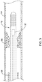
- Figure 1 illustrates a portion of an example medical device 10.
- medical device 10 is a blood pressure sensing guidewire 10.
- Guidewire 10 may include a tubular member or shaft 12.
- Shaft 12 may include a proximal portion 14 and a distal portion 16.
- the materials for proximal portion 14 and distal portion 16 may vary and may include those materials disclosed herein.
- distal portion 16 may include a nickel-cobalt-chromium-molybdenum alloy (e.g., MP35-N).
- Proximal portion 14 may be made from the same material as distal portion 16 or a different material such as stainless steel. These are just examples. Other materials are contemplated.
- proximal portion 14 and distal portion 16 are formed from the same monolith of material. In other words, proximal portion 14 and distal portion 16 are portions of the same tube defining shaft 12. In other embodiments, proximal portion 14 and distal portion 16 are separate tubular members that are joined together. For example, a section of the outer surface of portions 14/16 may be removed and a sleeve 17 may be disposed over the removed sections to join portions 14/16. Alternatively, sleeve 17 may be simply disposed over portions 14/16. Other bonds may also be used including welds, thermal bonds, adhesive bonds, or the like.
- sleeve 17 used to join proximal portion 14 with distal portion 16 may include a material that desirably bonds with both proximal portion 14 and distal portion 16.
- sleeve 17 may include a nickel-chromium-molybdenum alloy (e.g., INCONEL).
- a plurality of slots 18 may be formed in shaft 12. In at least some embodiments, slots 18 are formed in distal portion 16. In at least some embodiments, proximal portion 14 lacks slots 18. However, proximal portion 14 may include slots 18. Slots 18 may be desirable for a number of reasons. For example, slots 18 may provide a desirable level of flexibility to shaft 12 (e.g., along distal portion 16) while also allowing suitable transmission of torque. Slots 18 may be arranged/distributed along distal portion 16 in a suitable manner. For example, slots 18 may be arranged as opposing pairs of slots 18 that are distributed along the length of distal portion 16. In some embodiments, adjacent pairs of slots 18 may have a substantially constant spacing relative to one another. Alternatively, the spacing between adjacent pairs may vary.
- more distal regions of distal portion 16 may have a decreased spacing (and/or increased slot density), which may provide increased flexibility.
- more distal regions of distal portion 16 may have an increased spacing (and/or decreased slot density).
- a pressure sensor 20 may be disposed within shaft 12 (e.g., within a lumen of shaft 12). While pressure sensor 20 is shown schematically in Figure 1 , it can be appreciated that the structural form and/or type of pressure sensor 20 may vary.
- pressure sensor 20 may include a semiconductor (e.g., silicon wafer) pressure sensor, piezoelectric pressure sensor, a fiber optic or optical pressure sensor, a Fabry-Perot type pressure sensor, an ultrasound transducer and/or ultrasound pressure sensor, a magnetic pressure sensor, a solid-state pressure sensor, or the like, or any other suitable pressure sensor.
- pressure sensor 20 may include an optical pressure sensor.
- an optical fiber or fiber optic cable 24 (e.g., a multimode fiber optic) may be attached to pressure sensor 20 and may extend proximally therefrom.
- Optical fiber 24 may include a central core 60 and an outer cladding 62.
- a sealing member (not shown) may attach optical fiber 24 to shaft 12.
- Such an attachment member may be circumferentially disposed about and attached to optical fiber 24 and may be secured to the inner surface of shaft 12 (e.g., distal portion 16).
- a centering member 26 may also be bonded to optical fiber 24.
- centering member 26 is proximally spaced from pressure sensor 20. Other arrangements are contemplated. Centering member 26 may help reduce forces that may be exposed to pressure sensor 20 during navigation of guidewire and/or during use.
- distal portion 16 may include a region with a thinned wall and/or an increased inner diameter that defines a housing region 52.
- housing region 52 is the region of distal portion 16 that ultimately "houses" pressure sensor 20. By virtue of having a portion of the inner wall of shaft 12 being removed at housing region 52, additional space may be created or otherwise defined that can accommodate sensor 20. Housing region 52 may include one or more openings 66 that provides fluid access to pressure sensor 20.
- a tip member 30 may be coupled to distal portion 16.
- Tip member 30 may include a shaping member 32 and a spring or coil member 34.
- a distal tip 36 may be attached to shaping member 32 and/or spring 34.
- distal tip 36 may take the form of a solder ball tip.
- Tip member 30 may be joined to distal portion 16 of shaft 12 with a bonding member 46 such as a weld.
- Shaft 12 may include an outer coating 19.
- coating 19 may extend along substantially the full length of shaft 12.
- one or more discrete sections of shaft 12 may include coating 19.
- Coating 19 may be a hydrophobic coating, a hydrophilic coating, or the like.
- a clinician may use guidewire 10 to measure and/or calculate FFR (e.g., the pressure after an intravascular occlusion relative to the pressure before the occlusion and/or the aortic pressure).
- Measuring and/or calculating FFR may include measuring the aortic pressure in a patient. This may include advancing guidewire 10 through a blood vessel or body lumen 54 to a position that is proximal or upstream of an occlusion 56 as shown in Figure 2 .
- guidewire 10 may be advanced through a guide catheter 58 to a position where at least a portion of sensor 20 is disposed distal of the distal end of guide catheter 58 and measuring the pressure within body lumen 54. This pressure may be characterized as an initial pressure.
- the aortic pressure may also be measured by another device (e.g., a pressure sensing guidewire, catheter, or the like).
- the initial pressure may be equalized with the aortic pressure.
- the initial pressure measured by guidewire 10 may be set to be the same as the measured aortic pressure.
- Guidewire 10 may be further advanced to a position distal or downstream of occlusion 56 as shown in Figure 3 and the pressure within body lumen 54 may be measured. This pressure may be characterized as the downstream or distal pressure.
- the distal pressure and the aortic pressure may be used to calculate FFR.
- bubbles may be formed.
- guidewire 10 may be flushed with a fluid (e.g., saline).
- a fluid e.g., saline
- air bubbles may form.
- Some of these bubbles may become disposed within tubular member 12, for example within housing region 52. If the bubbles remain within tubular member 12, the bubbles could interact with pressure sensor 20 and possibly alter the pressure readings made by pressure sensor 20 and/or lead to the drifting of the pressure readings. It may be desirable to reduce or minimize these interactions and reduce pressure drift.
- hydrophilic coating 64 may be disposed along an inner surface of tubular member 12. Hydrophilic coating 64 may improve the wetting of the inner surface of tubular member and reduce the retention of bubbles. In at least some instances, hydrophilic coating 64 may be disposed adjacent to pressure sensor 20 and/or along housing region 52. For example, hydrophilic coating 64 may extend from the distal end of tubular member 12 to a position about 2-10cm (e.g., 5cm) proximally of pressure sensor 20. In some instances, hydrophilic coating 64 may extend proximally beyond housing region 52.
- hydrophilic coating 64 may include extending hydrophilic coating 64 down essentially the entire length of tubular member 12.
- proximal portion 14 of tubular member 12 may be free of hydrophilic coating 64.
- hydrophilic coating 64 is disposed only along the inner surface of tubular member 12.
- hydrophilic coating 64 is disposed along other portions of tubular member 12 including along the outer surface, along both the inner surface and the outer surface, along pressure sensor 20, or along other suitable portions of tubular member 12.
- the outer surface of tubular member 12 is free of hydrophilic coating 64.
- pressure sensor 20 is free of hydrophilic coating 64.
- hydrophilic coating 64 helps reduce bubble retention by reducing the contact angle between fluids contacting the surface of hydrophilic coating 64 and the surface of hydrophilic coating 64.
- hydrophilic coating reduces the contact angle to less than about 90°, or about 50° or less, or to about 30° or less, or to about 15° or less, or to about 10° or less, or to about 5° or less, or to less than 10°, or to less than 5°.
- Figures 4-6 schematically illustrate the reduction in contact angle that can be achieved using coating 64.
- Figure 4 illustrates a fluid droplet 68 in contact with hydrophilic coating 64.
- the contact angle may be about 30°.
- Figure 5 illustrates fluid droplet 68 contacting hydrophilic coating 64 with a contact angle of about 10°.
- Figure 6 illustrates fluid droplet 68 contacting hydrophilic coating 64 with a contact angle of about 5°.
- hydrophilic coating 64 may be a silicone-based hydrophilic material and, thus, form a hydrophilic silicone coating 64.
- silicone-based hydrophilic material is sold under the tradename SILPLEX (e.g., SILPLEX JQ-40), commercially available from Siltech LLC, Dacula, GA.
- hydrophilic coating 64 may be a hydrophobic material (e.g., a material that is typically seen as having hydrophobic properties) with hydrophilic properties.
- the hydrophilic coating 64 may include a silicone polyether polymer with both hydrophilic and hydrophobic components (e.g., where the hydrophilic component may include polyethylene oxide, polypropylene oxide, combinations thereof, or the like; and where the hydrophobic component may include a siloxane backbone).
- the ratio of polyethylene oxide and/or polypropylene oxide to siloxane can vary.
- contemplated coating materials may include SILSURF A008, C208, B608, C410, D208, or the like.
- the surfactant concentrations may vary from about 0-8%.
- the hydrophilic coating 64 may include a non-silicone material.
- the hydrophilic coating may include a surfactant that may function as an anti-foam agent to destabilize air bubbles.
- the coating material 64 may include a polymethyl acrylate, polyvinylpyrrolidone, or the like. Other materials are contemplated.
- Hydrophilic coating 64 may be disposed within tubular member 12 using a suitable method.
- hydrophilic coating 64 may be applied to the inner surface of tubular member 12 using a dip coating process.
- tubular member 12 may be dipped into a solution of hydrophilic coating 64 to a suitable depth (e.g. to a depth such that hydrophilic coating 64 extends proximally of pressure sensor 20).
- the outer surface of tubular member 12 may be masked to avoid coating the outer surface.
- the outer surface of tubular member 12 may also be coated with hydrophilic coating 64.
- the integrity and coverage of hydrophilic coating 64 can be inspected and verified, for example, using a microscope. If desired, additional layers of hydrophilic coating 64 can be applied.
- Hydrophilic coating 64 can be dried at room temperature in air (e.g., within a carrier tube and/or product packaging). Alternatively, hydrophilic coating can be dried in an oven, in a modified atmosphere, combinations thereof, or the like.
- the materials that can be used for the various components of guidewire 10 (and/or other guidewires disclosed herein) and the various tubular members disclosed herein may include those commonly associated with medical devices.
- the following discussion makes reference to shaft 12 and other components of guidewire 10.
- this is not intended to limit the devices and methods described herein, as the discussion may be applied to other tubular members and/or components of tubular members or devices disclosed herein.
- Shaft 12 and/or other components of guidewire 10 may be made from a metal, metal alloy, polymer (some examples of which are disclosed below), a metal-polymer composite, ceramics, combinations thereof, and the like, or other suitable material.
- suitable polymers may include polytetrafluoroethylene (PTFE), ethylene tetrafluoroethylene (ETFE), fluorinated ethylene propylene (FEP), polyoxymethylene (POM, for example, DELRIN® available from DuPont), polyether block ester, polyurethane (for example, Polyurethane 85A), polypropylene (PP), polyvinylchloride (PVC), polyether-ester (for example, ARNITEL® available from DSM Engineering Plastics), ether or ester based copolymers (for example, butylene/poly(alkylene ether) phthalate and/or other polyester elastomers such as HYTREL® available from DuPont), polyamide (for example, DURETHAN® available from Bay
- suitable metals and metal alloys include stainless steel, such as 304V, 304L, and 316LV stainless steel; mild steel; nickel-titanium alloy such as linear-elastic and/or super-elastic nitinol; other nickel alloys such as nickel-chromium-molybdenum alloys (e.g., UNS: N06625 such as INCONEL® 625, UNS: N06022 such as HASTELLOY® C-22®, UNS: N10276 such as HASTELLOY® C276®, other HASTELLOY® alloys, and the like), nickel-copper alloys (e.g., UNS: N04400 such as MONEL® 400, NICKELVAC® 400, NICORROS® 400, and the like), nickel-cobalt-chromium-molybdenum alloys (e.g., UNS: R30035 such as MP35-N® and the like), nickel-molybdenum alloys (e.g.,
- portions or all of guidewire 10 may also be doped with, made of, or otherwise include a radiopaque material.
- Radiopaque materials are understood to be materials capable of producing a relatively bright image on a fluoroscopy screen or another imaging technique during a medical procedure. This relatively bright image aids the user of guidewire 10 in determining its location.
- Some examples of radiopaque materials can include, but are not limited to, gold, platinum, palladium, tantalum, tungsten alloy, polymer material loaded with a radiopaque filler, and the like. Additionally, other radiopaque marker bands and/or coils may also be incorporated into the design of guidewire 10 to achieve the same result.
- a degree of Magnetic Resonance Imaging (MRI) compatibility is imparted into guidewire 10.
- guidewire 10, or portions thereof may be made of a material that does not substantially distort the image and create substantial artifacts (e.g., gaps in the image). Certain ferromagnetic materials, for example, may not be suitable because they may create artifacts in an MRI image.
- Guidewire 10, or portions thereof may also be made from a material that the MRI machine can image.
- Some materials that exhibit these characteristics include, for example, tungsten, cobalt-chromium-molybdenum alloys (e.g., UNS: R30003 such as ELGILOY®, PHYNOX®, and the like), nickel-cobalt-chromium-molybdenum alloys (e.g., UNS: R30035 such as MP35-N® and the like), nitinol, and the like, and others.
- cobalt-chromium-molybdenum alloys e.g., UNS: R30003 such as ELGILOY®, PHYNOX®, and the like
- nickel-cobalt-chromium-molybdenum alloys e.g., UNS: R30035 such as MP35-N® and the like
- nitinol and the like, and others.
Landscapes
- Health & Medical Sciences (AREA)
- Life Sciences & Earth Sciences (AREA)
- Veterinary Medicine (AREA)
- Animal Behavior & Ethology (AREA)
- Engineering & Computer Science (AREA)
- Biophysics (AREA)
- Biomedical Technology (AREA)
- Heart & Thoracic Surgery (AREA)
- Public Health (AREA)
- General Health & Medical Sciences (AREA)
- Cardiology (AREA)
- Surgery (AREA)
- Medical Informatics (AREA)
- Physics & Mathematics (AREA)
- Pathology (AREA)
- Molecular Biology (AREA)
- Physiology (AREA)
- Vascular Medicine (AREA)
- Hematology (AREA)
- Anesthesiology (AREA)
- Pulmonology (AREA)
- Measuring Pulse, Heart Rate, Blood Pressure Or Blood Flow (AREA)
- Media Introduction/Drainage Providing Device (AREA)
Description
- The present disclosure pertains to medical devices, and methods for manufacturing medical devices. More particularly, the present disclosure pertains to blood pressure sensing guidewires and methods for using pressure sensing guidewires.
- A wide variety of intracorporeal medical devices have been developed for medical use, for example, intravascular use. Some of these devices include guidewires, catheters, and the like. These devices are manufactured by any one of a variety of different manufacturing methods and may be used according to any one of a variety of methods. Of the known medical devices and methods, each has certain advantages and disadvantages. There is an ongoing need to provide alternative medical devices as well as alternative methods for manufacturing and using medical devices.
-
US 2007/255145 A1 relates to a sensor and guide wire assembly for intravascular measurements of a physiological variable in a living body, comprising: a sensor element and a sensor guide wire comprising a core wire and at least one signal transmitting cable connected to the sensor element, wherein a polymer layer is provided which encloses a portion of the core wire and said at least one signal transmitting cable. -
US 2013/274618 relates to a guidewire system, comprising: a tubular guidewire having an open proximal end, a closed distal end, and a length extending therebetween, the tubular guidewire including at least one lumen extending from the proximal end to the distal end; and at least one pressure wire slidably disposed within the at least one lumen, the at least one pressure wire having a length and at least one pressure sensor disposed thereon; wherein the tubular guidewire includes a plurality of apertures disposed through an outer wall of the tubular guidewire. -
US 2014/276109 A1 relates to a pressure sensing guidewire, comprising: a tubular member having a proximal portion and a distal portion; wherein the distal portion has a plurality of slots formed therein; wherein the distal portion has a first wall thickness along a first region and a second wall thickness different from the first wall thickness along a second region; and a pressure sensor disposed within the distal portion of the tubular member. -
WO 97/09926 A1 - The present invention is defined by the claims.
- This disclosure provides design, material, manufacturing method, and use alternatives for medical devices. An example medical device includes a pressure sensing guidewire. The pressure sensing guidewire comprises: a tubular member having a proximal region and a housing region; a pressure sensor disposed within the housing region; a signal transmitting member coupled to the pressure sensor and extending proximally therefrom; and a hydrophilic silicone coating disposed along an inner surface of the housing region.
- Alternatively or additionally to any of the embodiments above, the pressure sensor includes an optical pressure sensor.
- Alternatively or additionally to any of the embodiments above, the signal transmitting member includes an optical fiber.
- Alternatively or additionally to any of the embodiments above, a sensor port is formed in the housing region that is positioned adjacent to the pressure sensor and wherein the hydrophilic silicone coating extends proximally of the sensor port.
- Alternatively or additionally to any of the embodiments above, the proximal region of the tubular member is free of the hydrophilic silicone coating.
- Alternatively or additionally to any of the embodiments above, further comprising a centering member coupled to the signal transmitting member.
- Alternatively or additionally to any of the embodiments above, the hydrophilic silicone coating is designed so that blood contacting a surface of the hydrophilic silicone coating has a contact angle of about 50° or less.
- Alternatively or additionally to any of the embodiments above, the hydrophilic silicone coating is designed so that blood contacting a surface of the hydrophilic silicone coating has a contact angle of about 30° or less.
- Alternatively or additionally to any of the embodiments above, the hydrophilic silicone coating is designed so that blood contacting a surface of the hydrophilic silicone coating has a contact angle of about 10° or less.
- Alternatively or additionally to any of the embodiments above, the tubular member has a first wall thickness along the housing region, wherein the tubular member has a second wall thickness along the proximal region, and wherein the first wall thickness is smaller from the second wall thickness.
- Alternatively or additionally to any of the embodiments above, further comprising a centering member coupled to the signal transmitting member at a position adjacent to the pressure sensor.
- Alternatively or additionally to any of the embodiments above, further comprising a tip member coupled to the housing region and extending distally therefrom.
- A pressure sensing guidewire is disclosed. The pressure sensing guidewire comprises: a tubular member having a proximal region and a housing region; wherein the tubular member has a reduced wall thickness along the housing region; an optical pressure sensor disposed within the housing region; an optical fiber coupled to the optical pressure sensor and extending proximally therefrom; a hydrophilic coating disposed along an inner surface of the housing region; wherein the hydrophilic coating is designed so that blood contacting a surface of the hydrophilic coating has a contact angle of about 30° or less.
- Alternatively or additionally to any of the embodiments above, a sensor port is formed in the housing region that is positioned adjacent to the optical pressure sensor and wherein the hydrophilic coating extends proximally of the sensor port.
- Alternatively or additionally to any of the embodiments above, the proximal region of the tubular member is free of the hydrophilic coating.
- A pressure sensing guidewire is disclosed. The pressure sensing guidewire comprises: a tubular member having a proximal region and a housing region; an optical pressure sensor disposed within the housing region; an optical fiber coupled to the optical pressure sensor and extending proximally therefrom; a hydrophilic silicone coating disposed along an inner surface of the housing region, the hydrophilic silicone coating extending from a distal end of the housing region to a position proximal of the optical pressure sensor; and wherein the hydrophilic silicone coating is designed so that a body fluid contacting a surface of the hydrophilic silicone coating has a contact angle of about 10° or less such that retention of air bubbles within the housing region is reduced.
- Alternatively or additionally to any of the embodiments above, a sensor port is formed in the housing region that is positioned adjacent to the optical pressure sensor and wherein the hydrophilic silicone coating extends proximally of the sensor port.
- Alternatively or additionally to any of the embodiments above, the proximal region of the tubular member is free of the hydrophilic silicone coating.
- Alternatively or additionally to any of the embodiments above, the tubular member has a first wall thickness along the housing region, wherein the tubular member has a second wall thickness along the proximal region, and wherein the first wall thickness is smaller than the second wall thickness.
- Alternatively or additionally to any of the embodiments above, further comprising a hydrophobic coating disposed along an outer surface of the tubular member.
- The above summary of some embodiments is not intended to describe each disclosed embodiment or every implementation of the present disclosure. The Figures, and Detailed Description, which follow, more particularly exemplify these embodiments.
- The disclosure may be more completely understood in consideration of the following detailed description in connection with the accompanying drawings, in which:
-
Figure 1 is a partial cross-sectional side view of a portion of an example medical device. -
Figure 2 is a partial cross-sectional view of an example medical device disposed at a first position adjacent to an intravascular occlusion. -
Figure 3 is a partial cross-sectional view of an example medical device disposed at a second position adjacent to an intravascular occlusion. -
Figures 4-6 schematically illustrate a fluid interacting with a portion of an example medical device. - For the following defined terms, these definitions shall be applied, unless a different definition is given in the claims or elsewhere in this specification.
- All numeric values are herein assumed to be modified by the term "about", whether or not explicitly indicated. The term "about" generally refers to a range of numbers that one of skill in the art would consider equivalent to the recited value (e.g., having the same function or result). In many instances, the terms "about" may include numbers that are rounded to the nearest significant figure.
- The recitation of numerical ranges by endpoints includes all numbers within that range (e.g. 1 to 5 includes 1, 1.5, 2, 2.75, 3, 3.80, 4, and 5).
- As used in this specification and the appended claims, the singular forms "a", "an", and "the" include plural referents unless the content clearly dictates otherwise. As used in this specification and the appended claims, the term "or" is generally employed in its sense including "and/or" unless the content clearly dictates otherwise.
- It is noted that references in the specification to "an embodiment", "some embodiments", "other embodiments", etc., indicate that the embodiment described may include one or more particular features, structures, and/or characteristics. However, such recitations do not necessarily mean that all embodiments include the particular features, structures, and/or characteristics. Additionally, when particular features, structures, and/or characteristics are described in connection with one embodiment, it should be understood that such features, structures, and/or characteristics may also be used connection with other embodiments whether or not explicitly described unless clearly stated to the contrary.
- The following detailed description should be read with reference to the drawings in which similar elements in different drawings are numbered the same. The drawings, which are not necessarily to scale, depict illustrative embodiments and are not intended to limit the scope of the invention.
- During some medical interventions, it may be desirable to measure and/or monitor the blood pressure within a blood vessel. For example, some medical devices may include pressure sensors that allow a clinician to monitor blood pressure. Such devices may be useful in determining fractional flow reserve (FFR), which may be understood as the pressure after a stenosis relative to the pressure before the stenosis (and/or the aortic pressure).
-
Figure 1 illustrates a portion of an examplemedical device 10. In this example,medical device 10 is a bloodpressure sensing guidewire 10. However, this is not intended to be limiting as other medical devices are contemplated including, for example, catheters, shafts, leads, wires, or the like.Guidewire 10 may include a tubular member orshaft 12.Shaft 12 may include aproximal portion 14 and adistal portion 16. The materials forproximal portion 14 anddistal portion 16 may vary and may include those materials disclosed herein. For example,distal portion 16 may include a nickel-cobalt-chromium-molybdenum alloy (e.g., MP35-N).Proximal portion 14 may be made from the same material asdistal portion 16 or a different material such as stainless steel. These are just examples. Other materials are contemplated. - In some embodiments,
proximal portion 14 anddistal portion 16 are formed from the same monolith of material. In other words,proximal portion 14 anddistal portion 16 are portions of the sametube defining shaft 12. In other embodiments,proximal portion 14 anddistal portion 16 are separate tubular members that are joined together. For example, a section of the outer surface ofportions 14/16 may be removed and asleeve 17 may be disposed over the removed sections to joinportions 14/16. Alternatively,sleeve 17 may be simply disposed overportions 14/16. Other bonds may also be used including welds, thermal bonds, adhesive bonds, or the like. If utilized,sleeve 17 used to joinproximal portion 14 withdistal portion 16 may include a material that desirably bonds with bothproximal portion 14 anddistal portion 16. For example,sleeve 17 may include a nickel-chromium-molybdenum alloy (e.g., INCONEL). - A plurality of
slots 18 may be formed inshaft 12. In at least some embodiments,slots 18 are formed indistal portion 16. In at least some embodiments,proximal portion 14 lacksslots 18. However,proximal portion 14 may includeslots 18.Slots 18 may be desirable for a number of reasons. For example,slots 18 may provide a desirable level of flexibility to shaft 12 (e.g., along distal portion 16) while also allowing suitable transmission of torque.Slots 18 may be arranged/distributed alongdistal portion 16 in a suitable manner. For example,slots 18 may be arranged as opposing pairs ofslots 18 that are distributed along the length ofdistal portion 16. In some embodiments, adjacent pairs ofslots 18 may have a substantially constant spacing relative to one another. Alternatively, the spacing between adjacent pairs may vary. For example, more distal regions ofdistal portion 16 may have a decreased spacing (and/or increased slot density), which may provide increased flexibility. In other embodiments, more distal regions ofdistal portion 16 may have an increased spacing (and/or decreased slot density). These are just examples. Other arrangements are contemplated. - A
pressure sensor 20 may be disposed within shaft 12 (e.g., within a lumen of shaft 12). Whilepressure sensor 20 is shown schematically inFigure 1 , it can be appreciated that the structural form and/or type ofpressure sensor 20 may vary. For example,pressure sensor 20 may include a semiconductor (e.g., silicon wafer) pressure sensor, piezoelectric pressure sensor, a fiber optic or optical pressure sensor, a Fabry-Perot type pressure sensor, an ultrasound transducer and/or ultrasound pressure sensor, a magnetic pressure sensor, a solid-state pressure sensor, or the like, or any other suitable pressure sensor. - As indicated above,
pressure sensor 20 may include an optical pressure sensor. In at least some of these embodiments, an optical fiber or fiber optic cable 24 (e.g., a multimode fiber optic) may be attached topressure sensor 20 and may extend proximally therefrom.Optical fiber 24 may include acentral core 60 and anouter cladding 62. In some instances, a sealing member (not shown) may attachoptical fiber 24 toshaft 12. Such an attachment member may be circumferentially disposed about and attached tooptical fiber 24 and may be secured to the inner surface of shaft 12 (e.g., distal portion 16). In addition, a centeringmember 26 may also be bonded tooptical fiber 24. In at least some embodiments, centeringmember 26 is proximally spaced frompressure sensor 20. Other arrangements are contemplated. Centeringmember 26 may help reduce forces that may be exposed topressure sensor 20 during navigation of guidewire and/or during use. - In at least some embodiments,
distal portion 16 may include a region with a thinned wall and/or an increased inner diameter that defines ahousing region 52. In general,housing region 52 is the region ofdistal portion 16 that ultimately "houses"pressure sensor 20. By virtue of having a portion of the inner wall ofshaft 12 being removed athousing region 52, additional space may be created or otherwise defined that can accommodatesensor 20.Housing region 52 may include one ormore openings 66 that provides fluid access topressure sensor 20. - A
tip member 30 may be coupled todistal portion 16.Tip member 30 may include a shapingmember 32 and a spring orcoil member 34. Adistal tip 36 may be attached to shapingmember 32 and/orspring 34. In at least some embodiments,distal tip 36 may take the form of a solder ball tip.Tip member 30 may be joined todistal portion 16 ofshaft 12 with a bonding member 46 such as a weld. -
Shaft 12 may include anouter coating 19. In some embodiments, coating 19 may extend along substantially the full length ofshaft 12. In other embodiments, one or more discrete sections ofshaft 12 may includecoating 19.Coating 19 may be a hydrophobic coating, a hydrophilic coating, or the like. - In use, a clinician may use
guidewire 10 to measure and/or calculate FFR (e.g., the pressure after an intravascular occlusion relative to the pressure before the occlusion and/or the aortic pressure). Measuring and/or calculating FFR may include measuring the aortic pressure in a patient. This may include advancingguidewire 10 through a blood vessel orbody lumen 54 to a position that is proximal or upstream of anocclusion 56 as shown inFigure 2 . For example, guidewire 10 may be advanced through aguide catheter 58 to a position where at least a portion ofsensor 20 is disposed distal of the distal end ofguide catheter 58 and measuring the pressure withinbody lumen 54. This pressure may be characterized as an initial pressure. In some embodiments, the aortic pressure may also be measured by another device (e.g., a pressure sensing guidewire, catheter, or the like). The initial pressure may be equalized with the aortic pressure. For example, the initial pressure measured byguidewire 10 may be set to be the same as the measured aortic pressure.Guidewire 10 may be further advanced to a position distal or downstream ofocclusion 56 as shown inFigure 3 and the pressure withinbody lumen 54 may be measured. This pressure may be characterized as the downstream or distal pressure. The distal pressure and the aortic pressure may be used to calculate FFR. - During the preparation for use and/or during the use of
guidewire 10, it is possible that bubbles may be formed. For example, prior to insertingguidewire 10 into a patient, guidewire 10 may be flushed with a fluid (e.g., saline). During the flushing process, air bubbles may form. Some of these bubbles may become disposed withintubular member 12, for example withinhousing region 52. If the bubbles remain withintubular member 12, the bubbles could interact withpressure sensor 20 and possibly alter the pressure readings made bypressure sensor 20 and/or lead to the drifting of the pressure readings. It may be desirable to reduce or minimize these interactions and reduce pressure drift. - In order to reduce the amount of bubbles within
tubular member 12, reduce drift, and/or otherwise improve the pressure readings made bypressure sensor 20, ahydrophilic coating 64 may be disposed along an inner surface oftubular member 12.Hydrophilic coating 64 may improve the wetting of the inner surface of tubular member and reduce the retention of bubbles. In at least some instances,hydrophilic coating 64 may be disposed adjacent to pressuresensor 20 and/or alonghousing region 52. For example,hydrophilic coating 64 may extend from the distal end oftubular member 12 to a position about 2-10cm (e.g., 5cm) proximally ofpressure sensor 20. In some instances,hydrophilic coating 64 may extend proximally beyondhousing region 52. This may include extendinghydrophilic coating 64 down essentially the entire length oftubular member 12. Alternatively,proximal portion 14 oftubular member 12 may be free ofhydrophilic coating 64. In some instances,hydrophilic coating 64 is disposed only along the inner surface oftubular member 12. In some of these and in other instances,hydrophilic coating 64 is disposed along other portions oftubular member 12 including along the outer surface, along both the inner surface and the outer surface, alongpressure sensor 20, or along other suitable portions oftubular member 12. In some instances, the outer surface oftubular member 12 is free ofhydrophilic coating 64. In some of these and in other instances,pressure sensor 20 is free ofhydrophilic coating 64. - While not wishing to be bound by theory,
hydrophilic coating 64 helps reduce bubble retention by reducing the contact angle between fluids contacting the surface ofhydrophilic coating 64 and the surface ofhydrophilic coating 64. In some instances, hydrophilic coating reduces the contact angle to less than about 90°, or about 50° or less, or to about 30° or less, or to about 15° or less, or to about 10° or less, or to about 5° or less, or to less than 10°, or to less than 5°.Figures 4-6 schematically illustrate the reduction in contact angle that can be achieved usingcoating 64. For example,Figure 4 illustrates afluid droplet 68 in contact withhydrophilic coating 64. In this example, the contact angle may be about 30°.Figure 5 illustratesfluid droplet 68 contactinghydrophilic coating 64 with a contact angle of about 10°.Figure 6 illustratesfluid droplet 68 contactinghydrophilic coating 64 with a contact angle of about 5°. - A number of different materials are contemplated for
hydrophilic coating 64. For example, in at least some embodiments,hydrophilic coating 64 may be a silicone-based hydrophilic material and, thus, form ahydrophilic silicone coating 64. One example silicone-based hydrophilic material is sold under the tradename SILPLEX (e.g., SILPLEX JQ-40), commercially available from Siltech LLC, Dacula, GA. In some of these and in other instances,hydrophilic coating 64 may be a hydrophobic material (e.g., a material that is typically seen as having hydrophobic properties) with hydrophilic properties. In some instances, thehydrophilic coating 64 may include a silicone polyether polymer with both hydrophilic and hydrophobic components (e.g., where the hydrophilic component may include polyethylene oxide, polypropylene oxide, combinations thereof, or the like; and where the hydrophobic component may include a siloxane backbone). In such instances, the ratio of polyethylene oxide and/or polypropylene oxide to siloxane can vary. Some examples of contemplated coating materials may include SILSURF A008, C208, B608, C410, D208, or the like. The surfactant concentrations may vary from about 0-8%. In some instances, thehydrophilic coating 64 may include a non-silicone material. For example, the hydrophilic coating may include a surfactant that may function as an anti-foam agent to destabilize air bubbles. In still other instances, thecoating material 64 may include a polymethyl acrylate, polyvinylpyrrolidone, or the like. Other materials are contemplated. -
Hydrophilic coating 64 may be disposed withintubular member 12 using a suitable method. For example,hydrophilic coating 64 may be applied to the inner surface oftubular member 12 using a dip coating process. For example,tubular member 12 may be dipped into a solution ofhydrophilic coating 64 to a suitable depth (e.g. to a depth such thathydrophilic coating 64 extends proximally of pressure sensor 20). In some instances, the outer surface oftubular member 12 may be masked to avoid coating the outer surface. Alternatively, the outer surface oftubular member 12 may also be coated withhydrophilic coating 64. Upon completion, the integrity and coverage ofhydrophilic coating 64 can be inspected and verified, for example, using a microscope. If desired, additional layers ofhydrophilic coating 64 can be applied.Hydrophilic coating 64 can be dried at room temperature in air (e.g., within a carrier tube and/or product packaging). Alternatively, hydrophilic coating can be dried in an oven, in a modified atmosphere, combinations thereof, or the like. - The materials that can be used for the various components of guidewire 10 (and/or other guidewires disclosed herein) and the various tubular members disclosed herein may include those commonly associated with medical devices. For simplicity purposes, the following discussion makes reference to
shaft 12 and other components ofguidewire 10. However, this is not intended to limit the devices and methods described herein, as the discussion may be applied to other tubular members and/or components of tubular members or devices disclosed herein. -
Shaft 12 and/or other components ofguidewire 10 may be made from a metal, metal alloy, polymer (some examples of which are disclosed below), a metal-polymer composite, ceramics, combinations thereof, and the like, or other suitable material. Some examples of suitable polymers may include polytetrafluoroethylene (PTFE), ethylene tetrafluoroethylene (ETFE), fluorinated ethylene propylene (FEP), polyoxymethylene (POM, for example, DELRIN® available from DuPont), polyether block ester, polyurethane (for example, Polyurethane 85A), polypropylene (PP), polyvinylchloride (PVC), polyether-ester (for example, ARNITEL® available from DSM Engineering Plastics), ether or ester based copolymers (for example, butylene/poly(alkylene ether) phthalate and/or other polyester elastomers such as HYTREL® available from DuPont), polyamide (for example, DURETHAN® available from Bayer or CRISTAM1D® available from Elf Atochem), elastomeric polyamides, block polyamide/ethers, polyether block amide (PEBA, for example available under the trade name PEBAX®), ethylene vinyl acetate copolymers (EVA), silicones, polyethylene (PE), Marlex high-density polyethylene, Marlex low-density polyethylene, linear low density polyethylene (for example REXELL®), polyester, polybutylene terephthalate (PBT), polyethylene terephthalate (PET), polytrimethylene terephthalate, polyethylene naphthalate (PEN), polyetheretherketone (PEEK), polyimide (PI), polyetherimide (PEI), polyphenylene sulfide (PPS), polyphenylene oxide (PPO), poly paraphenylene terephthalamide (for example, KEVLAR®), polysulfone, nylon, nylon-12 (such as GRILAMID® available from EMS American Grilon), perfluoro(propyl vinyl ether) (PFA), ethylene vinyl alcohol, polyolefin, polystyrene, epoxy, polyvinylidene chloride (PVdC), poly(styrene-b-isobutylene-b-styrene) (for example, SIBS and/or SIBS 50A), polycarbonates, ionomers, biocompatible polymers, other suitable materials, or mixtures, combinations, copolymers thereof, polymer/metal composites, and the like. In some embodiments the sheath can be blended with a liquid crystal polymer (LCP). For example, the mixture can contain up to about 6 percent LCP. - Some examples of suitable metals and metal alloys include stainless steel, such as 304V, 304L, and 316LV stainless steel; mild steel; nickel-titanium alloy such as linear-elastic and/or super-elastic nitinol; other nickel alloys such as nickel-chromium-molybdenum alloys (e.g., UNS: N06625 such as INCONEL® 625, UNS: N06022 such as HASTELLOY® C-22®, UNS: N10276 such as HASTELLOY® C276®, other HASTELLOY® alloys, and the like), nickel-copper alloys (e.g., UNS: N04400 such as MONEL® 400, NICKELVAC® 400, NICORROS® 400, and the like), nickel-cobalt-chromium-molybdenum alloys (e.g., UNS: R30035 such as MP35-N® and the like), nickel-molybdenum alloys (e.g., UNS: N10665 such as HASTELLOY® ALLOY B2®), other nickel-chromium alloys, other nickel-molybdenum alloys, other nickel-cobalt alloys, other nickel-iron alloys, other nickel-copper alloys, other nickel-tungsten or tungsten alloys, and the like; cobalt-chromium alloys; cobalt-chromium-molybdenum alloys (e.g., UNS: R30003 such as ELGILOY®, PHYNOX®, and the like); platinum enriched stainless steel; titanium; combinations thereof; and the like; or any other suitable material.
- In at least some embodiments, portions or all of
guidewire 10 may also be doped with, made of, or otherwise include a radiopaque material. Radiopaque materials are understood to be materials capable of producing a relatively bright image on a fluoroscopy screen or another imaging technique during a medical procedure. This relatively bright image aids the user ofguidewire 10 in determining its location. Some examples of radiopaque materials can include, but are not limited to, gold, platinum, palladium, tantalum, tungsten alloy, polymer material loaded with a radiopaque filler, and the like. Additionally, other radiopaque marker bands and/or coils may also be incorporated into the design ofguidewire 10 to achieve the same result. - In some embodiments, a degree of Magnetic Resonance Imaging (MRI) compatibility is imparted into
guidewire 10. For example, guidewire 10, or portions thereof, may be made of a material that does not substantially distort the image and create substantial artifacts (e.g., gaps in the image). Certain ferromagnetic materials, for example, may not be suitable because they may create artifacts in an MRI image.Guidewire 10, or portions thereof, may also be made from a material that the MRI machine can image. Some materials that exhibit these characteristics include, for example, tungsten, cobalt-chromium-molybdenum alloys (e.g., UNS: R30003 such as ELGILOY®, PHYNOX®, and the like), nickel-cobalt-chromium-molybdenum alloys (e.g., UNS: R30035 such as MP35-N® and the like), nitinol, and the like, and others. - It should be understood that this disclosure is, in many respects, only illustrative. Changes may be made in details, particularly in matters of shape, size, and arrangement of steps without exceeding the scope of the disclosure. This may include, to the extent that it is appropriate, the use of any of the features of one example embodiment being used in other embodiments. The invention's scope is, of course, defined in the language in which the appended claims are expressed.
Claims (15)
- A pressure sensing guidewire (10), comprising:a tubular member (12) having a proximal region (14) and a distal region (16), wherein a housing region (52) is included in the distal region (16);a pressure sensor (20) disposed within the housing region;a signal transmitting member coupled to the pressure sensor (20) and extending proximally therefrom; characterized in that the pressure sensing guidewire further comprisesa hydrophilic silicone coating (64) disposed along an inner surface of the housing region (52).
- The pressure sensing guidewire of claim 1, wherein the pressure sensor includes (20) an optical pressure sensor.
- The pressure sensing guidewire of any one of claims 1-2, wherein the signal transmitting member includes an optical fiber (24).
- The pressure sensing guidewire of any one of claims 1-3, wherein a sensor port is formed in the housing region (52) that is positioned adjacent to the pressure sensor (20) and wherein the hydrophilic silicone coating (64) extends proximally of the sensor port.
- The pressure sensing guidewire of any one of claims 1-4, wherein the proximal region (14) of the tubular member (12) is free of the hydrophilic silicone coating (64).
- The pressure sensing guidewire of any one of claims 1-5, further comprising a centering member (26) coupled to the signal transmitting member.
- The pressure sensing guidewire of any one of claims 1-6, wherein the hydrophilic silicone coating (64) is designed so that blood contacting a surface of the hydrophilic silicone coating (64) has a contact angle of about 50° or less.
- The pressure sensing guidewire of any one of claims 1-6, wherein the hydrophilic silicone coating (64) is designed so that blood contacting a surface of the hydrophilic silicone coating (64) has a contact angle of about 30° or less.
- The pressure sensing guidewire of any one of claims 1-6, wherein the hydrophilic silicone coating (64) is designed so that blood contacting a surface of the hydrophilic silicone coating (64) has a contact angle of about 10° or less.
- The pressure sensing guidewire of any one of claims 1-9, wherein the tubular member (12) has a first wall thickness along the housing region (52), wherein the tubular member has a second wall thickness along the proximal region (14), and wherein the first wall thickness is smaller from the second wall thickness.
- The pressure sensing guidewire of any one of claims 1-10, further comprising a centering member (26) coupled to the signal transmitting member at a position adjacent to the pressure sensor (20).
- The pressure sensing guidewire of any one of claims 1-11, further comprising a tip member (30) coupled to the housing region (52) and extending distally therefrom.
- The pressure sensing guidewire (10) of claim 1, wherein the tubular member has a reduced wall thickness along the housing region;
wherein the pressure sensor (20) includes an optical pressure sensor disposed within the housing region;
wherein the signal transmitting member includes an optical fiber (24) coupled to the optical pressure sensor (20) and extending proximally therefrom; and
wherein the hydrophilic coating (64) is designed so that blood contacting a surface of the hydrophilic coating (64) has a contact angle of about 30° or less. - The pressure sensing guidewire of claim 13, wherein a sensor port is formed in the housing region (52) that is positioned adjacent to the optical pressure sensor and wherein the hydrophilic coating (64) extends proximally of the sensor port.
- The pressure sensing guidewire of any one of claims 13-14, wherein the proximal region (14) of the tubular member (12) is free of the hydrophilic coating (64).
Applications Claiming Priority (2)
| Application Number | Priority Date | Filing Date | Title |
|---|---|---|---|
| US201762460608P | 2017-02-17 | 2017-02-17 | |
| PCT/US2018/018529 WO2018152429A1 (en) | 2017-02-17 | 2018-02-17 | Medical device with pressure sensor |
Publications (2)
| Publication Number | Publication Date |
|---|---|
| EP3582845A1 EP3582845A1 (en) | 2019-12-25 |
| EP3582845B1 true EP3582845B1 (en) | 2021-01-06 |
Family
ID=61557345
Family Applications (1)
| Application Number | Title | Priority Date | Filing Date |
|---|---|---|---|
| EP18708526.1A Active EP3582845B1 (en) | 2017-02-17 | 2018-02-17 | Medical device with pressure sensor |
Country Status (5)
| Country | Link |
|---|---|
| US (1) | US20180235543A1 (en) |
| EP (1) | EP3582845B1 (en) |
| JP (1) | JP7026123B2 (en) |
| CN (1) | CN110582319A (en) |
| WO (1) | WO2018152429A1 (en) |
Families Citing this family (1)
| Publication number | Priority date | Publication date | Assignee | Title |
|---|---|---|---|---|
| JP2022191593A (en) * | 2021-06-16 | 2022-12-28 | 朝日インテック株式会社 | Resin coating wire and chemical injection device |
Family Cites Families (19)
| Publication number | Priority date | Publication date | Assignee | Title |
|---|---|---|---|---|
| JPS59228849A (en) * | 1983-06-10 | 1984-12-22 | テルモ株式会社 | Apparatus for removing air bubbles in liquid |
| US5097841A (en) * | 1988-09-22 | 1992-03-24 | Terumo Kabushiki Kaisha | Disposable pressure transducer and disposable pressure transducer apparatus |
| US5873835A (en) * | 1993-04-29 | 1999-02-23 | Scimed Life Systems, Inc. | Intravascular pressure and flow sensor |
| US5409015A (en) * | 1993-05-11 | 1995-04-25 | Target Therapeutics, Inc. | Deformable tip super elastic guidewire |
| US5731087A (en) * | 1995-06-07 | 1998-03-24 | Union Carbide Chemicals & Plastics Technology Corporation | Lubricious coatings containing polymers with vinyl and carboxylic acid moieties |
| JP4264269B2 (en) | 2003-01-30 | 2009-05-13 | 財団法人神奈川科学技術アカデミー | Hydrophilic tube and method for producing the same |
| US7699829B2 (en) * | 2004-03-25 | 2010-04-20 | Boston Scientific Scimed, Inc. | Catheter with sensor tip and method of use of same |
| US20070255145A1 (en) * | 2006-04-28 | 2007-11-01 | Radi Medical Systems Ab | Sensor and guide wire assembly |
| WO2008064245A2 (en) * | 2006-11-21 | 2008-05-29 | Ferry Steven J | Coating system |
| US20120209090A1 (en) * | 2011-02-14 | 2012-08-16 | Searete Llc, A Limited Liability Corporation Of The Sate Of Delaware | Systems, devices, and methods including implantable devices with anti-microbial properties |
| JP2012530052A (en) * | 2009-06-15 | 2012-11-29 | ディーエスエム アイピー アセッツ ビー.ブイ. | Medical amphiphilic silicones based on phosphorylcholine |
| US9655555B2 (en) | 2011-03-07 | 2017-05-23 | Potrero Medical, Inc. | Sensing foley catheter |
| US20130274618A1 (en) * | 2012-04-17 | 2013-10-17 | Boston Scientific Scimed, Inc. | Guidewire system for use in transcatheter aortic valve implantation procedures |
| US20160022244A1 (en) * | 2013-03-15 | 2016-01-28 | Colibri Technologies Inc. | Medical probes having internal hydrophilic surfaces |
| JP6441299B2 (en) | 2013-03-15 | 2018-12-19 | ボストン サイエンティフィック サイムド,インコーポレイテッドBoston Scientific Scimed,Inc. | Pressure sensing guide wire |
| CN105682544B (en) * | 2013-05-22 | 2019-09-24 | 波士顿科学国际有限公司 | Pressure detecting godet system including optical connector optical cable |
| CN106714675B (en) | 2014-08-01 | 2020-03-20 | 波士顿科学国际有限公司 | Pressure sensing guidewire |
| ES2814102T3 (en) * | 2015-02-26 | 2021-03-26 | St Jude Medical Coordination Ct Bvba | Guide wire with self-wetting tube |
| WO2017062839A1 (en) * | 2015-10-09 | 2017-04-13 | Vascular Imaging Corporation | Optical sensor assemblies and methods |
-
2018
- 2018-02-17 CN CN201880025105.9A patent/CN110582319A/en active Pending
- 2018-02-17 JP JP2019544687A patent/JP7026123B2/en active Active
- 2018-02-17 US US15/898,430 patent/US20180235543A1/en active Pending
- 2018-02-17 EP EP18708526.1A patent/EP3582845B1/en active Active
- 2018-02-17 WO PCT/US2018/018529 patent/WO2018152429A1/en unknown
Non-Patent Citations (1)
| Title |
|---|
| None * |
Also Published As
| Publication number | Publication date |
|---|---|
| CN110582319A (en) | 2019-12-17 |
| JP2020508741A (en) | 2020-03-26 |
| EP3582845A1 (en) | 2019-12-25 |
| JP7026123B2 (en) | 2022-02-25 |
| WO2018152429A1 (en) | 2018-08-23 |
| US20180235543A1 (en) | 2018-08-23 |
Similar Documents
| Publication | Publication Date | Title |
|---|---|---|
| JP6582129B2 (en) | Medical device and pressure sensing guidewire | |
| CN108366745B (en) | Pressure sensing guidewire | |
| EP3151739B1 (en) | Pressure sensing guidewire systems with reduced pressure offsets | |
| WO2015142623A1 (en) | Pressure sensing guidewires | |
| WO2015057518A1 (en) | Pressure sensing guidewire and methods for calculating fractional flow reserve | |
| EP3644846B1 (en) | Systems for assessing fractional flow reserve | |
| EP3174455B1 (en) | Pressure sensing guidewires | |
| US20240081741A1 (en) | Medical device with pressure sensor | |
| EP3226748B1 (en) | Pressure sensing guidewires | |
| EP3397147B1 (en) | Medical devices with antithrombogenic coatings | |
| EP3582845B1 (en) | Medical device with pressure sensor | |
| US11559213B2 (en) | Medical device with pressure sensor |
Legal Events
| Date | Code | Title | Description |
|---|---|---|---|
| STAA | Information on the status of an ep patent application or granted ep patent |
Free format text: STATUS: UNKNOWN |
|
| STAA | Information on the status of an ep patent application or granted ep patent |
Free format text: STATUS: THE INTERNATIONAL PUBLICATION HAS BEEN MADE |
|
| PUAI | Public reference made under article 153(3) epc to a published international application that has entered the european phase |
Free format text: ORIGINAL CODE: 0009012 |
|
| STAA | Information on the status of an ep patent application or granted ep patent |
Free format text: STATUS: REQUEST FOR EXAMINATION WAS MADE |
|
| 17P | Request for examination filed |
Effective date: 20190917 |
|
| AK | Designated contracting states |
Kind code of ref document: A1 Designated state(s): AL AT BE BG CH CY CZ DE DK EE ES FI FR GB GR HR HU IE IS IT LI LT LU LV MC MK MT NL NO PL PT RO RS SE SI SK SM TR |
|
| AX | Request for extension of the european patent |
Extension state: BA ME |
|
| DAV | Request for validation of the european patent (deleted) | ||
| DAX | Request for extension of the european patent (deleted) | ||
| GRAP | Despatch of communication of intention to grant a patent |
Free format text: ORIGINAL CODE: EPIDOSNIGR1 |
|
| STAA | Information on the status of an ep patent application or granted ep patent |
Free format text: STATUS: GRANT OF PATENT IS INTENDED |
|
| INTG | Intention to grant announced |
Effective date: 20200721 |
|
| GRAS | Grant fee paid |
Free format text: ORIGINAL CODE: EPIDOSNIGR3 |
|
| GRAA | (expected) grant |
Free format text: ORIGINAL CODE: 0009210 |
|
| STAA | Information on the status of an ep patent application or granted ep patent |
Free format text: STATUS: THE PATENT HAS BEEN GRANTED |
|
| AK | Designated contracting states |
Kind code of ref document: B1 Designated state(s): AL AT BE BG CH CY CZ DE DK EE ES FI FR GB GR HR HU IE IS IT LI LT LU LV MC MK MT NL NO PL PT RO RS SE SI SK SM TR |
|
| REG | Reference to a national code |
Ref country code: GB Ref legal event code: FG4D |
|
| REG | Reference to a national code |
Ref country code: AT Ref legal event code: REF Ref document number: 1351682 Country of ref document: AT Kind code of ref document: T Effective date: 20210115 Ref country code: CH Ref legal event code: EP |
|
| REG | Reference to a national code |
Ref country code: DE Ref legal event code: R096 Ref document number: 602018011640 Country of ref document: DE |
|
| REG | Reference to a national code |
Ref country code: IE Ref legal event code: FG4D |
|
| REG | Reference to a national code |
Ref country code: NL Ref legal event code: FP |
|
| REG | Reference to a national code |
Ref country code: AT Ref legal event code: MK05 Ref document number: 1351682 Country of ref document: AT Kind code of ref document: T Effective date: 20210106 |
|
| REG | Reference to a national code |
Ref country code: LT Ref legal event code: MG9D |
|
| PG25 | Lapsed in a contracting state [announced via postgrant information from national office to epo] |
Ref country code: BG Free format text: LAPSE BECAUSE OF FAILURE TO SUBMIT A TRANSLATION OF THE DESCRIPTION OR TO PAY THE FEE WITHIN THE PRESCRIBED TIME-LIMIT Effective date: 20210406 Ref country code: GR Free format text: LAPSE BECAUSE OF FAILURE TO SUBMIT A TRANSLATION OF THE DESCRIPTION OR TO PAY THE FEE WITHIN THE PRESCRIBED TIME-LIMIT Effective date: 20210407 Ref country code: HR Free format text: LAPSE BECAUSE OF FAILURE TO SUBMIT A TRANSLATION OF THE DESCRIPTION OR TO PAY THE FEE WITHIN THE PRESCRIBED TIME-LIMIT Effective date: 20210106 Ref country code: FI Free format text: LAPSE BECAUSE OF FAILURE TO SUBMIT A TRANSLATION OF THE DESCRIPTION OR TO PAY THE FEE WITHIN THE PRESCRIBED TIME-LIMIT Effective date: 20210106 Ref country code: LT Free format text: LAPSE BECAUSE OF FAILURE TO SUBMIT A TRANSLATION OF THE DESCRIPTION OR TO PAY THE FEE WITHIN THE PRESCRIBED TIME-LIMIT Effective date: 20210106 Ref country code: NO Free format text: LAPSE BECAUSE OF FAILURE TO SUBMIT A TRANSLATION OF THE DESCRIPTION OR TO PAY THE FEE WITHIN THE PRESCRIBED TIME-LIMIT Effective date: 20210406 Ref country code: PT Free format text: LAPSE BECAUSE OF FAILURE TO SUBMIT A TRANSLATION OF THE DESCRIPTION OR TO PAY THE FEE WITHIN THE PRESCRIBED TIME-LIMIT Effective date: 20210506 |
|
| PG25 | Lapsed in a contracting state [announced via postgrant information from national office to epo] |
Ref country code: SE Free format text: LAPSE BECAUSE OF FAILURE TO SUBMIT A TRANSLATION OF THE DESCRIPTION OR TO PAY THE FEE WITHIN THE PRESCRIBED TIME-LIMIT Effective date: 20210106 Ref country code: AT Free format text: LAPSE BECAUSE OF FAILURE TO SUBMIT A TRANSLATION OF THE DESCRIPTION OR TO PAY THE FEE WITHIN THE PRESCRIBED TIME-LIMIT Effective date: 20210106 Ref country code: LV Free format text: LAPSE BECAUSE OF FAILURE TO SUBMIT A TRANSLATION OF THE DESCRIPTION OR TO PAY THE FEE WITHIN THE PRESCRIBED TIME-LIMIT Effective date: 20210106 Ref country code: PL Free format text: LAPSE BECAUSE OF FAILURE TO SUBMIT A TRANSLATION OF THE DESCRIPTION OR TO PAY THE FEE WITHIN THE PRESCRIBED TIME-LIMIT Effective date: 20210106 Ref country code: RS Free format text: LAPSE BECAUSE OF FAILURE TO SUBMIT A TRANSLATION OF THE DESCRIPTION OR TO PAY THE FEE WITHIN THE PRESCRIBED TIME-LIMIT Effective date: 20210106 |
|
| PG25 | Lapsed in a contracting state [announced via postgrant information from national office to epo] |
Ref country code: IS Free format text: LAPSE BECAUSE OF FAILURE TO SUBMIT A TRANSLATION OF THE DESCRIPTION OR TO PAY THE FEE WITHIN THE PRESCRIBED TIME-LIMIT Effective date: 20210506 |
|
| REG | Reference to a national code |
Ref country code: DE Ref legal event code: R097 Ref document number: 602018011640 Country of ref document: DE |
|
| REG | Reference to a national code |
Ref country code: BE Ref legal event code: MM Effective date: 20210228 |
|
| PG25 | Lapsed in a contracting state [announced via postgrant information from national office to epo] |
Ref country code: SM Free format text: LAPSE BECAUSE OF FAILURE TO SUBMIT A TRANSLATION OF THE DESCRIPTION OR TO PAY THE FEE WITHIN THE PRESCRIBED TIME-LIMIT Effective date: 20210106 Ref country code: CH Free format text: LAPSE BECAUSE OF NON-PAYMENT OF DUE FEES Effective date: 20210228 Ref country code: LU Free format text: LAPSE BECAUSE OF NON-PAYMENT OF DUE FEES Effective date: 20210217 Ref country code: LI Free format text: LAPSE BECAUSE OF NON-PAYMENT OF DUE FEES Effective date: 20210228 Ref country code: MC Free format text: LAPSE BECAUSE OF FAILURE TO SUBMIT A TRANSLATION OF THE DESCRIPTION OR TO PAY THE FEE WITHIN THE PRESCRIBED TIME-LIMIT Effective date: 20210106 Ref country code: EE Free format text: LAPSE BECAUSE OF FAILURE TO SUBMIT A TRANSLATION OF THE DESCRIPTION OR TO PAY THE FEE WITHIN THE PRESCRIBED TIME-LIMIT Effective date: 20210106 Ref country code: CZ Free format text: LAPSE BECAUSE OF FAILURE TO SUBMIT A TRANSLATION OF THE DESCRIPTION OR TO PAY THE FEE WITHIN THE PRESCRIBED TIME-LIMIT Effective date: 20210106 |
|
| PLBE | No opposition filed within time limit |
Free format text: ORIGINAL CODE: 0009261 |
|
| STAA | Information on the status of an ep patent application or granted ep patent |
Free format text: STATUS: NO OPPOSITION FILED WITHIN TIME LIMIT |
|
| PG25 | Lapsed in a contracting state [announced via postgrant information from national office to epo] |
Ref country code: DK Free format text: LAPSE BECAUSE OF FAILURE TO SUBMIT A TRANSLATION OF THE DESCRIPTION OR TO PAY THE FEE WITHIN THE PRESCRIBED TIME-LIMIT Effective date: 20210106 Ref country code: SK Free format text: LAPSE BECAUSE OF FAILURE TO SUBMIT A TRANSLATION OF THE DESCRIPTION OR TO PAY THE FEE WITHIN THE PRESCRIBED TIME-LIMIT Effective date: 20210106 Ref country code: RO Free format text: LAPSE BECAUSE OF FAILURE TO SUBMIT A TRANSLATION OF THE DESCRIPTION OR TO PAY THE FEE WITHIN THE PRESCRIBED TIME-LIMIT Effective date: 20210106 |
|
| 26N | No opposition filed |
Effective date: 20211007 |
|
| PG25 | Lapsed in a contracting state [announced via postgrant information from national office to epo] |
Ref country code: AL Free format text: LAPSE BECAUSE OF FAILURE TO SUBMIT A TRANSLATION OF THE DESCRIPTION OR TO PAY THE FEE WITHIN THE PRESCRIBED TIME-LIMIT Effective date: 20210106 Ref country code: ES Free format text: LAPSE BECAUSE OF FAILURE TO SUBMIT A TRANSLATION OF THE DESCRIPTION OR TO PAY THE FEE WITHIN THE PRESCRIBED TIME-LIMIT Effective date: 20210106 |
|
| PGFP | Annual fee paid to national office [announced via postgrant information from national office to epo] |
Ref country code: GB Payment date: 20211230 Year of fee payment: 5 |
|
| PG25 | Lapsed in a contracting state [announced via postgrant information from national office to epo] |
Ref country code: SI Free format text: LAPSE BECAUSE OF FAILURE TO SUBMIT A TRANSLATION OF THE DESCRIPTION OR TO PAY THE FEE WITHIN THE PRESCRIBED TIME-LIMIT Effective date: 20210106 |
|
| PG25 | Lapsed in a contracting state [announced via postgrant information from national office to epo] |
Ref country code: IT Free format text: LAPSE BECAUSE OF FAILURE TO SUBMIT A TRANSLATION OF THE DESCRIPTION OR TO PAY THE FEE WITHIN THE PRESCRIBED TIME-LIMIT Effective date: 20210106 |
|
| PG25 | Lapsed in a contracting state [announced via postgrant information from national office to epo] |
Ref country code: IS Free format text: LAPSE BECAUSE OF FAILURE TO SUBMIT A TRANSLATION OF THE DESCRIPTION OR TO PAY THE FEE WITHIN THE PRESCRIBED TIME-LIMIT Effective date: 20210506 |
|
| PGFP | Annual fee paid to national office [announced via postgrant information from national office to epo] |
Ref country code: FR Payment date: 20220118 Year of fee payment: 5 |
|
| PG25 | Lapsed in a contracting state [announced via postgrant information from national office to epo] |
Ref country code: BE Free format text: LAPSE BECAUSE OF NON-PAYMENT OF DUE FEES Effective date: 20210228 |
|
| PG25 | Lapsed in a contracting state [announced via postgrant information from national office to epo] |
Ref country code: CY Free format text: LAPSE BECAUSE OF FAILURE TO SUBMIT A TRANSLATION OF THE DESCRIPTION OR TO PAY THE FEE WITHIN THE PRESCRIBED TIME-LIMIT Effective date: 20210106 |
|
| PG25 | Lapsed in a contracting state [announced via postgrant information from national office to epo] |
Ref country code: HU Free format text: LAPSE BECAUSE OF FAILURE TO SUBMIT A TRANSLATION OF THE DESCRIPTION OR TO PAY THE FEE WITHIN THE PRESCRIBED TIME-LIMIT; INVALID AB INITIO Effective date: 20180217 |
|
| GBPC | Gb: european patent ceased through non-payment of renewal fee |
Effective date: 20230217 |
|
| PG25 | Lapsed in a contracting state [announced via postgrant information from national office to epo] |
Ref country code: GB Free format text: LAPSE BECAUSE OF NON-PAYMENT OF DUE FEES Effective date: 20230217 |
|
| PG25 | Lapsed in a contracting state [announced via postgrant information from national office to epo] |
Ref country code: GB Free format text: LAPSE BECAUSE OF NON-PAYMENT OF DUE FEES Effective date: 20230217 Ref country code: FR Free format text: LAPSE BECAUSE OF NON-PAYMENT OF DUE FEES Effective date: 20230228 |
|
| PGFP | Annual fee paid to national office [announced via postgrant information from national office to epo] |
Ref country code: NL Payment date: 20240123 Year of fee payment: 7 |
|
| PGFP | Annual fee paid to national office [announced via postgrant information from national office to epo] |
Ref country code: IE Payment date: 20240125 Year of fee payment: 7 |
|
| PG25 | Lapsed in a contracting state [announced via postgrant information from national office to epo] |
Ref country code: MK Free format text: LAPSE BECAUSE OF FAILURE TO SUBMIT A TRANSLATION OF THE DESCRIPTION OR TO PAY THE FEE WITHIN THE PRESCRIBED TIME-LIMIT Effective date: 20210106 |
|
| PGFP | Annual fee paid to national office [announced via postgrant information from national office to epo] |
Ref country code: DE Payment date: 20240123 Year of fee payment: 7 |