CN106999054B - Bedside interface for percutaneous coronary intervention planning - Google Patents
Bedside interface for percutaneous coronary intervention planning Download PDFInfo
- Publication number
- CN106999054B CN106999054B CN201580066722.XA CN201580066722A CN106999054B CN 106999054 B CN106999054 B CN 106999054B CN 201580066722 A CN201580066722 A CN 201580066722A CN 106999054 B CN106999054 B CN 106999054B
- Authority
- CN
- China
- Prior art keywords
- vessel
- instrument
- image
- pressure
- visualization
- Prior art date
- Legal status (The legal status is an assumption and is not a legal conclusion. Google has not performed a legal analysis and makes no representation as to the accuracy of the status listed.)
- Active
Links
- 238000013146 percutaneous coronary intervention Methods 0.000 title description 8
- 238000012800 visualization Methods 0.000 claims abstract description 70
- 238000009530 blood pressure measurement Methods 0.000 claims abstract description 52
- 238000011282 treatment Methods 0.000 claims description 65
- 238000012545 processing Methods 0.000 claims description 52
- 238000004891 communication Methods 0.000 claims description 37
- 238000012014 optical coherence tomography Methods 0.000 claims description 15
- 238000002608 intravascular ultrasound Methods 0.000 claims description 11
- 238000002591 computed tomography Methods 0.000 claims description 10
- 238000002405 diagnostic procedure Methods 0.000 claims description 6
- 238000002399 angioplasty Methods 0.000 claims description 4
- 239000008177 pharmaceutical agent Substances 0.000 claims description 3
- 230000004044 response Effects 0.000 claims description 3
- 238000004088 simulation Methods 0.000 claims description 2
- 208000031481 Pathologic Constriction Diseases 0.000 abstract description 52
- 230000036262 stenosis Effects 0.000 abstract description 50
- 208000037804 stenosis Diseases 0.000 abstract description 50
- 238000005259 measurement Methods 0.000 abstract description 9
- 210000004204 blood vessel Anatomy 0.000 abstract description 6
- 230000003902 lesion Effects 0.000 abstract description 4
- 238000000034 method Methods 0.000 description 71
- 239000012530 fluid Substances 0.000 description 24
- 238000012544 monitoring process Methods 0.000 description 22
- 230000000007 visual effect Effects 0.000 description 16
- 238000003384 imaging method Methods 0.000 description 15
- 239000003795 chemical substances by application Substances 0.000 description 12
- 230000000544 hyperemic effect Effects 0.000 description 12
- 238000010586 diagram Methods 0.000 description 9
- OIRDTQYFTABQOQ-KQYNXXCUSA-N adenosine Chemical compound C1=NC=2C(N)=NC=NC=2N1[C@@H]1O[C@H](CO)[C@@H](O)[C@H]1O OIRDTQYFTABQOQ-KQYNXXCUSA-N 0.000 description 8
- 238000004458 analytical method Methods 0.000 description 7
- 230000003287 optical effect Effects 0.000 description 7
- 238000003860 storage Methods 0.000 description 7
- CCEKAJIANROZEO-UHFFFAOYSA-N sulfluramid Chemical group CCNS(=O)(=O)C(F)(F)C(F)(F)C(F)(F)C(F)(F)C(F)(F)C(F)(F)C(F)(F)C(F)(F)F CCEKAJIANROZEO-UHFFFAOYSA-N 0.000 description 7
- 230000002792 vascular Effects 0.000 description 7
- 238000002583 angiography Methods 0.000 description 6
- 230000008569 process Effects 0.000 description 6
- 239000002126 C01EB10 - Adenosine Substances 0.000 description 4
- 229960005305 adenosine Drugs 0.000 description 4
- 230000017531 blood circulation Effects 0.000 description 4
- 210000004351 coronary vessel Anatomy 0.000 description 4
- 238000002595 magnetic resonance imaging Methods 0.000 description 4
- 230000001360 synchronised effect Effects 0.000 description 4
- 238000002604 ultrasonography Methods 0.000 description 4
- 210000005166 vasculature Anatomy 0.000 description 4
- 230000000694 effects Effects 0.000 description 3
- 230000000670 limiting effect Effects 0.000 description 3
- 230000004089 microcirculation Effects 0.000 description 3
- 239000007787 solid Substances 0.000 description 3
- 238000001356 surgical procedure Methods 0.000 description 3
- 208000007536 Thrombosis Diseases 0.000 description 2
- 210000000709 aorta Anatomy 0.000 description 2
- 230000008901 benefit Effects 0.000 description 2
- 238000004364 calculation method Methods 0.000 description 2
- 230000000747 cardiac effect Effects 0.000 description 2
- 201000010099 disease Diseases 0.000 description 2
- 208000037265 diseases, disorders, signs and symptoms Diseases 0.000 description 2
- 230000010102 embolization Effects 0.000 description 2
- 238000011156 evaluation Methods 0.000 description 2
- 230000000004 hemodynamic effect Effects 0.000 description 2
- 230000023597 hemostasis Effects 0.000 description 2
- 238000004519 manufacturing process Methods 0.000 description 2
- 238000012986 modification Methods 0.000 description 2
- 230000004048 modification Effects 0.000 description 2
- 239000013316 polymer of intrinsic microporosity Substances 0.000 description 2
- APTZNLHMIGJTEW-UHFFFAOYSA-N pyraflufen-ethyl Chemical compound C1=C(Cl)C(OCC(=O)OCC)=CC(C=2C(=C(OC(F)F)N(C)N=2)Cl)=C1F APTZNLHMIGJTEW-UHFFFAOYSA-N 0.000 description 2
- 230000002829 reductive effect Effects 0.000 description 2
- 239000004065 semiconductor Substances 0.000 description 2
- 238000002560 therapeutic procedure Methods 0.000 description 2
- 229920001621 AMOLED Polymers 0.000 description 1
- OYPRJOBELJOOCE-UHFFFAOYSA-N Calcium Chemical compound [Ca] OYPRJOBELJOOCE-UHFFFAOYSA-N 0.000 description 1
- 208000006545 Chronic Obstructive Pulmonary Disease Diseases 0.000 description 1
- RYGMFSIKBFXOCR-UHFFFAOYSA-N Copper Chemical compound [Cu] RYGMFSIKBFXOCR-UHFFFAOYSA-N 0.000 description 1
- 201000000057 Coronary Stenosis Diseases 0.000 description 1
- 208000001953 Hypotension Diseases 0.000 description 1
- 208000000913 Kidney Calculi Diseases 0.000 description 1
- 206010028980 Neoplasm Diseases 0.000 description 1
- 206010029148 Nephrolithiasis Diseases 0.000 description 1
- 244000208734 Pisonia aculeata Species 0.000 description 1
- 241001422033 Thestylus Species 0.000 description 1
- 208000027418 Wounds and injury Diseases 0.000 description 1
- 238000010317 ablation therapy Methods 0.000 description 1
- 230000009471 action Effects 0.000 description 1
- 230000004075 alteration Effects 0.000 description 1
- 210000003484 anatomy Anatomy 0.000 description 1
- 210000001367 artery Anatomy 0.000 description 1
- 208000006673 asthma Diseases 0.000 description 1
- 230000005540 biological transmission Effects 0.000 description 1
- 239000008280 blood Substances 0.000 description 1
- 210000004369 blood Anatomy 0.000 description 1
- 230000036471 bradycardia Effects 0.000 description 1
- 208000006218 bradycardia Diseases 0.000 description 1
- 229910052791 calcium Inorganic materials 0.000 description 1
- 239000011575 calcium Substances 0.000 description 1
- 230000001413 cellular effect Effects 0.000 description 1
- 230000008859 change Effects 0.000 description 1
- 238000012512 characterization method Methods 0.000 description 1
- 238000002512 chemotherapy Methods 0.000 description 1
- 230000001427 coherent effect Effects 0.000 description 1
- 239000003086 colorant Substances 0.000 description 1
- 238000010968 computed tomography angiography Methods 0.000 description 1
- 238000007596 consolidation process Methods 0.000 description 1
- 229910052802 copper Inorganic materials 0.000 description 1
- 239000010949 copper Substances 0.000 description 1
- 238000002574 cystoscopy Methods 0.000 description 1
- 230000006378 damage Effects 0.000 description 1
- 238000013481 data capture Methods 0.000 description 1
- 238000013480 data collection Methods 0.000 description 1
- 238000002059 diagnostic imaging Methods 0.000 description 1
- 239000003814 drug Substances 0.000 description 1
- 230000009977 dual effect Effects 0.000 description 1
- 238000002592 echocardiography Methods 0.000 description 1
- 238000002091 elastography Methods 0.000 description 1
- 238000005516 engineering process Methods 0.000 description 1
- 239000000835 fiber Substances 0.000 description 1
- 238000002594 fluoroscopy Methods 0.000 description 1
- 230000036543 hypotension Effects 0.000 description 1
- 208000014674 injury Diseases 0.000 description 1
- 238000003780 insertion Methods 0.000 description 1
- 230000037431 insertion Effects 0.000 description 1
- 230000010354 integration Effects 0.000 description 1
- 230000003993 interaction Effects 0.000 description 1
- 208000028867 ischemia Diseases 0.000 description 1
- 210000003141 lower extremity Anatomy 0.000 description 1
- 238000007726 management method Methods 0.000 description 1
- 238000013507 mapping Methods 0.000 description 1
- 239000000463 material Substances 0.000 description 1
- 230000007246 mechanism Effects 0.000 description 1
- 229910052751 metal Inorganic materials 0.000 description 1
- 239000002184 metal Substances 0.000 description 1
- 150000002739 metals Chemical class 0.000 description 1
- 239000000203 mixture Substances 0.000 description 1
- 230000000877 morphologic effect Effects 0.000 description 1
- 208000010125 myocardial infarction Diseases 0.000 description 1
- 230000001338 necrotic effect Effects 0.000 description 1
- 230000006855 networking Effects 0.000 description 1
- 230000036961 partial effect Effects 0.000 description 1
- 230000037361 pathway Effects 0.000 description 1
- 230000002093 peripheral effect Effects 0.000 description 1
- 230000000144 pharmacologic effect Effects 0.000 description 1
- 230000003389 potentiating effect Effects 0.000 description 1
- 230000001737 promoting effect Effects 0.000 description 1
- 230000009467 reduction Effects 0.000 description 1
- 238000002271 resection Methods 0.000 description 1
- 238000005096 rolling process Methods 0.000 description 1
- 239000000523 sample Substances 0.000 description 1
- 230000035807 sensation Effects 0.000 description 1
- 230000035945 sensitivity Effects 0.000 description 1
- 238000000926 separation method Methods 0.000 description 1
- 230000003068 static effect Effects 0.000 description 1
- 230000002966 stenotic effect Effects 0.000 description 1
- 238000012360 testing method Methods 0.000 description 1
- 229920001169 thermoplastic Polymers 0.000 description 1
- 229920001187 thermosetting polymer Polymers 0.000 description 1
- 239000004416 thermosoftening plastic Substances 0.000 description 1
- 238000013175 transesophageal echocardiography Methods 0.000 description 1
- 229940124549 vasodilator Drugs 0.000 description 1
- 239000003071 vasodilator agent Substances 0.000 description 1
Images


Classifications
-
- G—PHYSICS
- G16—INFORMATION AND COMMUNICATION TECHNOLOGY [ICT] SPECIALLY ADAPTED FOR SPECIFIC APPLICATION FIELDS
- G16H—HEALTHCARE INFORMATICS, i.e. INFORMATION AND COMMUNICATION TECHNOLOGY [ICT] SPECIALLY ADAPTED FOR THE HANDLING OR PROCESSING OF MEDICAL OR HEALTHCARE DATA
- G16H30/00—ICT specially adapted for the handling or processing of medical images
- G16H30/40—ICT specially adapted for the handling or processing of medical images for processing medical images, e.g. editing
-
- A—HUMAN NECESSITIES
- A61—MEDICAL OR VETERINARY SCIENCE; HYGIENE
- A61B—DIAGNOSIS; SURGERY; IDENTIFICATION
- A61B34/00—Computer-aided surgery; Manipulators or robots specially adapted for use in surgery
- A61B34/10—Computer-aided planning, simulation or modelling of surgical operations
-
- A—HUMAN NECESSITIES
- A61—MEDICAL OR VETERINARY SCIENCE; HYGIENE
- A61B—DIAGNOSIS; SURGERY; IDENTIFICATION
- A61B5/00—Measuring for diagnostic purposes; Identification of persons
- A61B5/0033—Features or image-related aspects of imaging apparatus classified in A61B5/00, e.g. for MRI, optical tomography or impedance tomography apparatus; arrangements of imaging apparatus in a room
- A61B5/0035—Features or image-related aspects of imaging apparatus classified in A61B5/00, e.g. for MRI, optical tomography or impedance tomography apparatus; arrangements of imaging apparatus in a room adapted for acquisition of images from more than one imaging mode, e.g. combining MRI and optical tomography
-
- A—HUMAN NECESSITIES
- A61—MEDICAL OR VETERINARY SCIENCE; HYGIENE
- A61B—DIAGNOSIS; SURGERY; IDENTIFICATION
- A61B5/00—Measuring for diagnostic purposes; Identification of persons
- A61B5/0033—Features or image-related aspects of imaging apparatus classified in A61B5/00, e.g. for MRI, optical tomography or impedance tomography apparatus; arrangements of imaging apparatus in a room
- A61B5/004—Features or image-related aspects of imaging apparatus classified in A61B5/00, e.g. for MRI, optical tomography or impedance tomography apparatus; arrangements of imaging apparatus in a room adapted for image acquisition of a particular organ or body part
-
- A—HUMAN NECESSITIES
- A61—MEDICAL OR VETERINARY SCIENCE; HYGIENE
- A61B—DIAGNOSIS; SURGERY; IDENTIFICATION
- A61B5/00—Measuring for diagnostic purposes; Identification of persons
- A61B5/0059—Measuring for diagnostic purposes; Identification of persons using light, e.g. diagnosis by transillumination, diascopy, fluorescence
- A61B5/0062—Arrangements for scanning
- A61B5/0066—Optical coherence imaging
-
- A—HUMAN NECESSITIES
- A61—MEDICAL OR VETERINARY SCIENCE; HYGIENE
- A61B—DIAGNOSIS; SURGERY; IDENTIFICATION
- A61B5/00—Measuring for diagnostic purposes; Identification of persons
- A61B5/0059—Measuring for diagnostic purposes; Identification of persons using light, e.g. diagnosis by transillumination, diascopy, fluorescence
- A61B5/0082—Measuring for diagnostic purposes; Identification of persons using light, e.g. diagnosis by transillumination, diascopy, fluorescence adapted for particular medical purposes
- A61B5/0084—Measuring for diagnostic purposes; Identification of persons using light, e.g. diagnosis by transillumination, diascopy, fluorescence adapted for particular medical purposes for introduction into the body, e.g. by catheters
-
- A—HUMAN NECESSITIES
- A61—MEDICAL OR VETERINARY SCIENCE; HYGIENE
- A61B—DIAGNOSIS; SURGERY; IDENTIFICATION
- A61B5/00—Measuring for diagnostic purposes; Identification of persons
- A61B5/02—Detecting, measuring or recording pulse, heart rate, blood pressure or blood flow; Combined pulse/heart-rate/blood pressure determination; Evaluating a cardiovascular condition not otherwise provided for, e.g. using combinations of techniques provided for in this group with electrocardiography or electroauscultation; Heart catheters for measuring blood pressure
- A61B5/02007—Evaluating blood vessel condition, e.g. elasticity, compliance
-
- A—HUMAN NECESSITIES
- A61—MEDICAL OR VETERINARY SCIENCE; HYGIENE
- A61B—DIAGNOSIS; SURGERY; IDENTIFICATION
- A61B5/00—Measuring for diagnostic purposes; Identification of persons
- A61B5/02—Detecting, measuring or recording pulse, heart rate, blood pressure or blood flow; Combined pulse/heart-rate/blood pressure determination; Evaluating a cardiovascular condition not otherwise provided for, e.g. using combinations of techniques provided for in this group with electrocardiography or electroauscultation; Heart catheters for measuring blood pressure
- A61B5/021—Measuring pressure in heart or blood vessels
- A61B5/0215—Measuring pressure in heart or blood vessels by means inserted into the body
-
- A—HUMAN NECESSITIES
- A61—MEDICAL OR VETERINARY SCIENCE; HYGIENE
- A61B—DIAGNOSIS; SURGERY; IDENTIFICATION
- A61B5/00—Measuring for diagnostic purposes; Identification of persons
- A61B5/05—Detecting, measuring or recording for diagnosis by means of electric currents or magnetic fields; Measuring using microwaves or radio waves
- A61B5/055—Detecting, measuring or recording for diagnosis by means of electric currents or magnetic fields; Measuring using microwaves or radio waves involving electronic [EMR] or nuclear [NMR] magnetic resonance, e.g. magnetic resonance imaging
-
- A—HUMAN NECESSITIES
- A61—MEDICAL OR VETERINARY SCIENCE; HYGIENE
- A61B—DIAGNOSIS; SURGERY; IDENTIFICATION
- A61B5/00—Measuring for diagnostic purposes; Identification of persons
- A61B5/68—Arrangements of detecting, measuring or recording means, e.g. sensors, in relation to patient
- A61B5/6846—Arrangements of detecting, measuring or recording means, e.g. sensors, in relation to patient specially adapted to be brought in contact with an internal body part, i.e. invasive
- A61B5/6867—Arrangements of detecting, measuring or recording means, e.g. sensors, in relation to patient specially adapted to be brought in contact with an internal body part, i.e. invasive specially adapted to be attached or implanted in a specific body part
- A61B5/6876—Blood vessel
-
- A—HUMAN NECESSITIES
- A61—MEDICAL OR VETERINARY SCIENCE; HYGIENE
- A61B—DIAGNOSIS; SURGERY; IDENTIFICATION
- A61B5/00—Measuring for diagnostic purposes; Identification of persons
- A61B5/72—Signal processing specially adapted for physiological signals or for diagnostic purposes
- A61B5/7235—Details of waveform analysis
- A61B5/7264—Classification of physiological signals or data, e.g. using neural networks, statistical classifiers, expert systems or fuzzy systems
-
- A—HUMAN NECESSITIES
- A61—MEDICAL OR VETERINARY SCIENCE; HYGIENE
- A61B—DIAGNOSIS; SURGERY; IDENTIFICATION
- A61B5/00—Measuring for diagnostic purposes; Identification of persons
- A61B5/74—Details of notification to user or communication with user or patient ; user input means
- A61B5/742—Details of notification to user or communication with user or patient ; user input means using visual displays
- A61B5/743—Displaying an image simultaneously with additional graphical information, e.g. symbols, charts, function plots
-
- A—HUMAN NECESSITIES
- A61—MEDICAL OR VETERINARY SCIENCE; HYGIENE
- A61B—DIAGNOSIS; SURGERY; IDENTIFICATION
- A61B6/00—Apparatus for radiation diagnosis, e.g. combined with radiation therapy equipment
- A61B6/02—Devices for diagnosis sequentially in different planes; Stereoscopic radiation diagnosis
- A61B6/03—Computerised tomographs
- A61B6/032—Transmission computed tomography [CT]
-
- A—HUMAN NECESSITIES
- A61—MEDICAL OR VETERINARY SCIENCE; HYGIENE
- A61B—DIAGNOSIS; SURGERY; IDENTIFICATION
- A61B6/00—Apparatus for radiation diagnosis, e.g. combined with radiation therapy equipment
- A61B6/12—Devices for detecting or locating foreign bodies
-
- A—HUMAN NECESSITIES
- A61—MEDICAL OR VETERINARY SCIENCE; HYGIENE
- A61B—DIAGNOSIS; SURGERY; IDENTIFICATION
- A61B6/00—Apparatus for radiation diagnosis, e.g. combined with radiation therapy equipment
- A61B6/46—Apparatus for radiation diagnosis, e.g. combined with radiation therapy equipment with special arrangements for interfacing with the operator or the patient
- A61B6/461—Displaying means of special interest
-
- A—HUMAN NECESSITIES
- A61—MEDICAL OR VETERINARY SCIENCE; HYGIENE
- A61B—DIAGNOSIS; SURGERY; IDENTIFICATION
- A61B6/00—Apparatus for radiation diagnosis, e.g. combined with radiation therapy equipment
- A61B6/46—Apparatus for radiation diagnosis, e.g. combined with radiation therapy equipment with special arrangements for interfacing with the operator or the patient
- A61B6/467—Apparatus for radiation diagnosis, e.g. combined with radiation therapy equipment with special arrangements for interfacing with the operator or the patient characterised by special input means
- A61B6/469—Apparatus for radiation diagnosis, e.g. combined with radiation therapy equipment with special arrangements for interfacing with the operator or the patient characterised by special input means for selecting a region of interest [ROI]
-
- A—HUMAN NECESSITIES
- A61—MEDICAL OR VETERINARY SCIENCE; HYGIENE
- A61B—DIAGNOSIS; SURGERY; IDENTIFICATION
- A61B6/00—Apparatus for radiation diagnosis, e.g. combined with radiation therapy equipment
- A61B6/50—Clinical applications
- A61B6/504—Clinical applications involving diagnosis of blood vessels, e.g. by angiography
-
- A—HUMAN NECESSITIES
- A61—MEDICAL OR VETERINARY SCIENCE; HYGIENE
- A61B—DIAGNOSIS; SURGERY; IDENTIFICATION
- A61B8/00—Diagnosis using ultrasonic, sonic or infrasonic waves
- A61B8/06—Measuring blood flow
-
- A—HUMAN NECESSITIES
- A61—MEDICAL OR VETERINARY SCIENCE; HYGIENE
- A61B—DIAGNOSIS; SURGERY; IDENTIFICATION
- A61B8/00—Diagnosis using ultrasonic, sonic or infrasonic waves
- A61B8/08—Detecting organic movements or changes, e.g. tumours, cysts, swellings
- A61B8/0891—Detecting organic movements or changes, e.g. tumours, cysts, swellings for diagnosis of blood vessels
-
- A—HUMAN NECESSITIES
- A61—MEDICAL OR VETERINARY SCIENCE; HYGIENE
- A61B—DIAGNOSIS; SURGERY; IDENTIFICATION
- A61B8/00—Diagnosis using ultrasonic, sonic or infrasonic waves
- A61B8/12—Diagnosis using ultrasonic, sonic or infrasonic waves in body cavities or body tracts, e.g. by using catheters
-
- A—HUMAN NECESSITIES
- A61—MEDICAL OR VETERINARY SCIENCE; HYGIENE
- A61B—DIAGNOSIS; SURGERY; IDENTIFICATION
- A61B8/00—Diagnosis using ultrasonic, sonic or infrasonic waves
- A61B8/52—Devices using data or image processing specially adapted for diagnosis using ultrasonic, sonic or infrasonic waves
- A61B8/5215—Devices using data or image processing specially adapted for diagnosis using ultrasonic, sonic or infrasonic waves involving processing of medical diagnostic data
- A61B8/5223—Devices using data or image processing specially adapted for diagnosis using ultrasonic, sonic or infrasonic waves involving processing of medical diagnostic data for extracting a diagnostic or physiological parameter from medical diagnostic data
-
- A—HUMAN NECESSITIES
- A61—MEDICAL OR VETERINARY SCIENCE; HYGIENE
- A61F—FILTERS IMPLANTABLE INTO BLOOD VESSELS; PROSTHESES; DEVICES PROVIDING PATENCY TO, OR PREVENTING COLLAPSING OF, TUBULAR STRUCTURES OF THE BODY, e.g. STENTS; ORTHOPAEDIC, NURSING OR CONTRACEPTIVE DEVICES; FOMENTATION; TREATMENT OR PROTECTION OF EYES OR EARS; BANDAGES, DRESSINGS OR ABSORBENT PADS; FIRST-AID KITS
- A61F2/00—Filters implantable into blood vessels; Prostheses, i.e. artificial substitutes or replacements for parts of the body; Appliances for connecting them with the body; Devices providing patency to, or preventing collapsing of, tubular structures of the body, e.g. stents
- A61F2/82—Devices providing patency to, or preventing collapsing of, tubular structures of the body, e.g. stents
-
- G—PHYSICS
- G06—COMPUTING; CALCULATING OR COUNTING
- G06F—ELECTRIC DIGITAL DATA PROCESSING
- G06F3/00—Input arrangements for transferring data to be processed into a form capable of being handled by the computer; Output arrangements for transferring data from processing unit to output unit, e.g. interface arrangements
- G06F3/01—Input arrangements or combined input and output arrangements for interaction between user and computer
- G06F3/048—Interaction techniques based on graphical user interfaces [GUI]
- G06F3/0481—Interaction techniques based on graphical user interfaces [GUI] based on specific properties of the displayed interaction object or a metaphor-based environment, e.g. interaction with desktop elements like windows or icons, or assisted by a cursor's changing behaviour or appearance
- G06F3/04815—Interaction with a metaphor-based environment or interaction object displayed as three-dimensional, e.g. changing the user viewpoint with respect to the environment or object
-
- G—PHYSICS
- G06—COMPUTING; CALCULATING OR COUNTING
- G06F—ELECTRIC DIGITAL DATA PROCESSING
- G06F3/00—Input arrangements for transferring data to be processed into a form capable of being handled by the computer; Output arrangements for transferring data from processing unit to output unit, e.g. interface arrangements
- G06F3/01—Input arrangements or combined input and output arrangements for interaction between user and computer
- G06F3/048—Interaction techniques based on graphical user interfaces [GUI]
- G06F3/0487—Interaction techniques based on graphical user interfaces [GUI] using specific features provided by the input device, e.g. functions controlled by the rotation of a mouse with dual sensing arrangements, or of the nature of the input device, e.g. tap gestures based on pressure sensed by a digitiser
- G06F3/0488—Interaction techniques based on graphical user interfaces [GUI] using specific features provided by the input device, e.g. functions controlled by the rotation of a mouse with dual sensing arrangements, or of the nature of the input device, e.g. tap gestures based on pressure sensed by a digitiser using a touch-screen or digitiser, e.g. input of commands through traced gestures
-
- G—PHYSICS
- G16—INFORMATION AND COMMUNICATION TECHNOLOGY [ICT] SPECIALLY ADAPTED FOR SPECIFIC APPLICATION FIELDS
- G16H—HEALTHCARE INFORMATICS, i.e. INFORMATION AND COMMUNICATION TECHNOLOGY [ICT] SPECIALLY ADAPTED FOR THE HANDLING OR PROCESSING OF MEDICAL OR HEALTHCARE DATA
- G16H30/00—ICT specially adapted for the handling or processing of medical images
- G16H30/20—ICT specially adapted for the handling or processing of medical images for handling medical images, e.g. DICOM, HL7 or PACS
-
- G—PHYSICS
- G16—INFORMATION AND COMMUNICATION TECHNOLOGY [ICT] SPECIALLY ADAPTED FOR SPECIFIC APPLICATION FIELDS
- G16H—HEALTHCARE INFORMATICS, i.e. INFORMATION AND COMMUNICATION TECHNOLOGY [ICT] SPECIALLY ADAPTED FOR THE HANDLING OR PROCESSING OF MEDICAL OR HEALTHCARE DATA
- G16H40/00—ICT specially adapted for the management or administration of healthcare resources or facilities; ICT specially adapted for the management or operation of medical equipment or devices
- G16H40/60—ICT specially adapted for the management or administration of healthcare resources or facilities; ICT specially adapted for the management or operation of medical equipment or devices for the operation of medical equipment or devices
- G16H40/63—ICT specially adapted for the management or administration of healthcare resources or facilities; ICT specially adapted for the management or operation of medical equipment or devices for the operation of medical equipment or devices for local operation
-
- G—PHYSICS
- G16—INFORMATION AND COMMUNICATION TECHNOLOGY [ICT] SPECIALLY ADAPTED FOR SPECIFIC APPLICATION FIELDS
- G16H—HEALTHCARE INFORMATICS, i.e. INFORMATION AND COMMUNICATION TECHNOLOGY [ICT] SPECIALLY ADAPTED FOR THE HANDLING OR PROCESSING OF MEDICAL OR HEALTHCARE DATA
- G16H50/00—ICT specially adapted for medical diagnosis, medical simulation or medical data mining; ICT specially adapted for detecting, monitoring or modelling epidemics or pandemics
- G16H50/50—ICT specially adapted for medical diagnosis, medical simulation or medical data mining; ICT specially adapted for detecting, monitoring or modelling epidemics or pandemics for simulation or modelling of medical disorders
-
- A—HUMAN NECESSITIES
- A61—MEDICAL OR VETERINARY SCIENCE; HYGIENE
- A61B—DIAGNOSIS; SURGERY; IDENTIFICATION
- A61B34/00—Computer-aided surgery; Manipulators or robots specially adapted for use in surgery
- A61B34/10—Computer-aided planning, simulation or modelling of surgical operations
- A61B2034/101—Computer-aided simulation of surgical operations
-
- A—HUMAN NECESSITIES
- A61—MEDICAL OR VETERINARY SCIENCE; HYGIENE
- A61B—DIAGNOSIS; SURGERY; IDENTIFICATION
- A61B34/00—Computer-aided surgery; Manipulators or robots specially adapted for use in surgery
- A61B34/10—Computer-aided planning, simulation or modelling of surgical operations
- A61B2034/107—Visualisation of planned trajectories or target regions
-
- A—HUMAN NECESSITIES
- A61—MEDICAL OR VETERINARY SCIENCE; HYGIENE
- A61B—DIAGNOSIS; SURGERY; IDENTIFICATION
- A61B5/00—Measuring for diagnostic purposes; Identification of persons
- A61B5/02—Detecting, measuring or recording pulse, heart rate, blood pressure or blood flow; Combined pulse/heart-rate/blood pressure determination; Evaluating a cardiovascular condition not otherwise provided for, e.g. using combinations of techniques provided for in this group with electrocardiography or electroauscultation; Heart catheters for measuring blood pressure
- A61B5/021—Measuring pressure in heart or blood vessels
- A61B5/0215—Measuring pressure in heart or blood vessels by means inserted into the body
- A61B5/02158—Measuring pressure in heart or blood vessels by means inserted into the body provided with two or more sensor elements
-
- A—HUMAN NECESSITIES
- A61—MEDICAL OR VETERINARY SCIENCE; HYGIENE
- A61B—DIAGNOSIS; SURGERY; IDENTIFICATION
- A61B5/00—Measuring for diagnostic purposes; Identification of persons
- A61B5/68—Arrangements of detecting, measuring or recording means, e.g. sensors, in relation to patient
- A61B5/6846—Arrangements of detecting, measuring or recording means, e.g. sensors, in relation to patient specially adapted to be brought in contact with an internal body part, i.e. invasive
- A61B5/6847—Arrangements of detecting, measuring or recording means, e.g. sensors, in relation to patient specially adapted to be brought in contact with an internal body part, i.e. invasive mounted on an invasive device
- A61B5/6852—Catheters
-
- A—HUMAN NECESSITIES
- A61—MEDICAL OR VETERINARY SCIENCE; HYGIENE
- A61B—DIAGNOSIS; SURGERY; IDENTIFICATION
- A61B5/00—Measuring for diagnostic purposes; Identification of persons
- A61B5/74—Details of notification to user or communication with user or patient ; user input means
- A61B5/742—Details of notification to user or communication with user or patient ; user input means using visual displays
- A61B5/7445—Display arrangements, e.g. multiple display units
Abstract
A system configured to assess the severity of a blockage in a vessel (and in particular a stenosis in a blood vessel) is disclosed. It is further disclosed to provide a measurement of the vessel allowing an assessment of the vessel (and in particular any stenosis or lesion of the vessel), simulating a diagnostic visualization with the first visualization means and the second visualization means. Displaying an image of the vessel on a first visualization device with a theranostic visualization based on the obtained pressure measurements and displaying a portion of the image of the vessel on a second visualization device with a diagnostic visualization based on the obtained pressure measurements, wherein the portion of the image of the vessel displayed on the second visualization device is an enlarged view of a region of interest of the vessel is disclosed.
Description
Technical Field
The present disclosure relates generally to the assessment of vessels using a bedside interface. For example, some embodiments of the present disclosure are suitable for assessing the severity of a blockage or other restriction in the flow of fluid through a vessel (e.g., a stenosis in a human blood vessel) by analyzing medical sensing data collected from the vessel using a touch-sensitive display of a bedside interface for use in Percutaneous Coronary Intervention (PCI) planning.
Background
Innovations in diagnosing and verifying the level of success of disease treatment have evolved from purely external imaging procedures to including internal diagnostic procedures. Small sensors can now be placed directly in the body, in addition to traditional external imaging techniques such as X-ray, MRI (magnetic resonance imaging), CT (computed tomography) scanning, fluoroscopy, and angiography. For example, diagnostic devices and procedures have been developed for diagnosing blockages of the vasculature and other diseases of the vasculature by way of a subminiature sensor placed on the distal end of a flexible elongate member (e.g., a catheter or guidewire for catheterization). For example, known medical sensing techniques include intravascular ultrasound (IVUS), prospective IVUS (FL-IVUS), Fractional Flow Reserve (FFR) determination, fractional Coronary Flow Reserve (CFR) determination, Optical Coherence Tomography (OCT), transesophageal echocardiography, and image-guided therapy. Traditionally, many such procedures are performed by a large number of doctors and clinicians, each performing an assigned task. For example, a physician may stand alongside a patient in a sterile field and guide the insertion and retraction of a medical sensing catheter. Clinicians in the vicinity of the physician may utilize the interface to control the surgical workflow, for example, by starting and stopping acquisition of medical data. Furthermore, once the medical data has been obtained, a second clinician working at a desktop computer in an adjacent control room may analyze the data, for example, by reviewing quantities calculated from the acquired data. If the display is usable in a sterile area, it is static and the physician may need to view several images in succession. Also, a physician in a catheter laboratory and a clinician in a control room must communicate to obtain and analyze relevant medical data. This may extend the time of the procedure, increase the cost of the procedure, and may lead to errors due to poor communication or inadequate clinician experience. US20140188503 discloses a system with a dual display device, a boom display and a bedside touchscreen controller.
A currently accepted technique for assessing the severity of stenosis in a blood vessel, including ischemia-induced injury, is Fractional Flow Reserve (FFR). FFR is the calculation of the ratio of a distal pressure measurement (taken on the distal side of the stenosis) to a proximal pressure measurement (taken on the proximal side of the stenosis). FFR provides an index of stenosis severity that allows a determination of whether the occlusion limits blood flow in the vessel to the extent that treatment is needed. The normal value of FFR in healthy vessels is 1.00, while values below about 0.80 are generally considered to be of major concern and require treatment. Common treatment options include angioplasty and stenting. Coronary blood flow is unique in that it is influenced not only by fluctuations in pressure occurring proximally in the microcirculation (as in the aorta), but also by fluctuations occurring distally in the microcirculation. Thus, it is not possible to accurately assess the severity of a coronary stenosis by measuring only the decrease in mean or peak pressure across the stenosis, since the distal coronary pressure is not purely a residual of the pressure transmitted from the aortic end of the vessel. Therefore, in order to effectively calculate FFR in the coronary artery, it is necessary to reduce vascular resistance in the vessel. At present, pharmacological hyperemic agents such as adenosine are administered to reduce and stabilize resistance in the coronary arteries. These potent vasodilators reduce the sharp fluctuations in resistance, primarily by reducing the resistance of the microcirculation associated with the systolic part of the cardiac cycle, so as to obtain a relatively stable and minimal resistance value.
However, administration of hyperemic agents is not always feasible or desirable. First, the clinical task of administering hyperemic agents can be significant. Hyperemic agents such as adenosine are expensive in some countries (particularly the united states) and are time consuming to obtain when delivered Intravenously (IV). In this regard, intravenously delivered adenosine is often mixed in hospital pharmacies on a case-by-case basis. This takes a great deal of time and effort to prepare and deliver adenosine to the surgical site. These logistical obstacles can influence the physician's decision to use FFR. Second, some patients have contraindications to use hyperemic agents, such as asthma, severe chronic obstructive pulmonary disease, hypotension, bradycardia, low cardiac ejection fraction, recent myocardial infarction, and/or other factors that prohibit administration of hyperemic agents. Third, many patients find administration of hyperemic agents uncomfortable, which is exacerbated only by the fact that multiple administrations of hyperemic agents may be required during the procedure used to obtain FFR measurements. Fourth, administration of hyperemic agents may also require central venous pathways (e.g., central venous sheaths) that may otherwise be avoided. Finally, not all patients respond as expected to a hyperemic agent, and in some cases, it is difficult to identify these patients prior to administration of the hyperemic agent.
Accordingly, there remains a need for improved devices, systems, and methods for assessing the severity of blockages in vessels and, in particular, stenoses in blood vessels. There is also a need for improved devices, systems and methods for providing a visual depiction of a vessel that allows for the assessment of the vessel and in particular any stenosis or lesion of the vessel. Furthermore, there is a need to assess the severity of stenosis and to provide a visual depiction of the vessel in an efficient and user-friendly manner to facilitate PCI planning.
Disclosure of Invention
Embodiments of the present disclosure are configured to assess the severity of a blockage in a vessel and in particular a stenosis in a vessel, provide a visual depiction of the vessel that allows assessment of the vessel and in particular any stenosis or lesion in the vessel, and simulate one or more treatment options of the vessel for facilitating planning and performance of a percutaneous coronary intervention.
As an example, a method of planning treatment of a vessel of a patient is provided. The methods include obtaining pressure measurements from a first instrument and a second instrument disposed within a vessel of a patient during a diagnostic procedure, wherein the second instrument is moved longitudinally through the vessel from a first position to a second position and the first instrument remains stationary within the vessel; an image of the vessel with a theranostic visualization based on the obtained pressure measurements is displayed on a first visualization device, and a portion of the image of the vessel with a theranostic visualization based on the obtained pressure measurements is displayed on a second visualization device, wherein the portion of the image of the vessel displayed on the second visualization device is an enlarged view of a region of interest of the vessel.
In certain embodiments, the first visualization device and the second visualization device are used to guide placement of one or more treatment devices associated with the determined treatment option. The second developing device may also include a touch screen. The image displayed on the second developing device may be at a higher magnification than the image displayed on the first developing device. The second developing device may have a higher magnification ratio than the first developing device.
In some cases, the image of the vessel includes an extravascular image and may be at least one of a two-dimensional angiographic image, a three-dimensional angiographic image, and a Computed Tomography Angiographic (CTA) image. Alternatively, the image of the vessel comprises an intravascular image and may be at least one of an intravascular ultrasound (IVUS) image and an Optical Coherence Tomography (OCT) image.
The diagnostic visualizations may include at least one of a pressure measurement from the first instrument, a pressure measurement from the second instrument, a ratio of pressure measurements from the first and second instruments, an FFR value, or an iFR value. Further, the diagnostic visualizations may include a brightness profile based on changes in a pressure ratio of the pressure measurements obtained from the first and second instruments or a gradient map of the pressure ratio of the pressure measurements obtained from the first and second instruments.
In one embodiment, a first treatment option is simulated, wherein simulating the first treatment option includes modifying the diagnostic visualizations based on expected results of the first treatment option. Further, a second treatment option can be simulated, wherein simulating the second treatment option includes modifying the diagnostic visualizations based on an expected outcome of the second treatment option; and comparing the modified diagnostic visualizations associated with the first and second treatment options to determine a recommended treatment option. The first and second treatment options may be selected from the group consisting of performing angioplasty, deploying one or more stents, applying a pharmaceutical agent, or a combination thereof.
There is also provided a system for planning the treatment of a vessel of a patient, comprising: a first instrument sized and shaped for introduction into a vessel of a patient; a second instrument sized and shaped for introduction into a vessel of a patient; a processing system in communication with a first instrument and a second instrument, the processing unit configured to: obtaining pressure measurements from a first instrument and a second instrument disposed within a vessel of a patient during a diagnostic procedure, wherein the second instrument is moved longitudinally through the vessel from a first position to a second position and the first instrument remains stationary within the vessel; displaying an image of the vessel on a first visualization device with a theranostic visualization based on the obtained pressure measurements; and displaying a portion of the image of the vessel based on the obtained pressure measurements on a second visualization device, wherein the portion of the image of the vessel displayed on the second visualization device is an enlarged view of a region of interest of the vessel.
In certain embodiments, the first visualization device and the second visualization device are used to guide placement of one or more treatment devices associated with the determined treatment option. The second developing device may also include a touch screen. The image displayed on the second developing device may be at a higher magnification than the image displayed on the first developing device. The second developing device may have a higher magnification ratio than the first developing device.
In some cases, the image of the vessel includes an extravascular image and may be at least one of a two-dimensional angiographic image, a three-dimensional angiographic image, and a Computed Tomography Angiographic (CTA) image. Alternatively, the image of the vessel comprises an intravascular image and may be at least one of an intravascular ultrasound (IVUS) image and an Optical Coherence Tomography (OCT) image.
The diagnostic visualizations may include at least one of pressure measurements from the first instrument, pressure measurements from the second instrument, a ratio of pressure measurements from the first and second measurement instruments, an FFR value, or an iFR value. Further, the diagnostic visualizations may include a brightness profile based on changes in a pressure ratio of the pressure measurements obtained from the first and second instruments or a gradient profile of the pressure ratio of the pressure measurements obtained from the first and second instruments.
In one embodiment, a first treatment option is simulated, wherein simulating the first treatment option includes modifying the diagnostic visualizations based on expected results of the first treatment option. Further, a second treatment option can be simulated, wherein simulating the second treatment option includes modifying the diagnostic visualizations based on an expected outcome of the second treatment option; and comparing the modified diagnostic visualizations associated with the first and second treatment options to determine a recommended treatment option. The first and second treatment options may be selected from the group consisting of performing angioplasty, deploying one or more stents, applying a pharmaceutical agent, or a combination thereof.
Additional aspects, features and advantages of the present disclosure will become apparent from the following detailed description.
Drawings
Illustrative embodiments of the present disclosure will be described with reference to the accompanying drawings, in which:
fig. 1 is a schematic diagram depicting a medical sensing system including a bedside interface according to one embodiment of the present disclosure.
Fig. 2 is a schematic diagram depicting a medical sensing system including a wireless bedside interface according to another embodiment of the present disclosure.
Fig. 3 is a schematic diagram depicting medical image display on a boom display and bedside interface according to one embodiment of the present disclosure.
Fig. 4 is a schematic diagram depicting medical image display on a boom display and bedside interface according to one embodiment of the present disclosure.
Fig. 5 is a functional block diagram of the bedside interface of fig. 3-4, in accordance with aspects of the present disclosure.
Fig. 6 is a flow chart illustrating an exemplary method for guiding a medical sensing workflow using a bedside interface.
Fig. 7 shows a diagrammatic perspective view of a vessel with a stenosis according to an exemplary illustration.
Figure 8 shows a diagrammatic, partially cross-sectional perspective view of a portion of the vessel of figure 7 taken along section line 9-9 of figure 7.
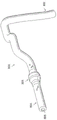
Figure 9 shows a diagrammatic, partially cut-away perspective view of the vessel of figures 7 and 8 with an instrument disposed therein according to one embodiment of the present disclosure.
Fig. 10 shows a diagrammatic schematic view of a system according to an embodiment of the disclosure.
Detailed Description
For the purposes of promoting an understanding of the principles of the disclosure, reference will now be made to the embodiments illustrated in the drawings and specific language will be used to describe the same. It will nevertheless be understood that no limitation of the scope of the disclosure is thereby intended. Any alterations and further modifications in the described devices, systems, and any further applications of the principles of the disclosure are contemplated as would normally occur to one skilled in the art to which the disclosure relates and which are intended to be included within the scope of the disclosure. In particular, it is fully contemplated that the features, components, and/or steps described in connection with one embodiment may be combined with the features, components, and/or steps described in connection with other embodiments of the present disclosure. However, for simplicity, multiple iterations of these combinations will not be described separately.
Fig. 1 is a schematic diagram depicting a medical sensing system 100 including a bedside interface 102 according to one embodiment of the present disclosure. In general, the medical sensing system 100 provides coherent integration and consolidation of multiple forms of acquisition and processing elements designed to be sensitive to multiple methods to acquire and interpret human biophysiological and morphological information. More specifically, in the system 100, the bedside interface 102 is a touch-integrated computing device for acquiring, controlling, interpreting, measuring, and displaying medical sensing data. In the illustrated embodiment, the bedside interface 102 is a tablet-style touch-sensitive computer that provides user control and diagnostic images on a single surface. In the medical sensing system 100, the bedside interface 102 is operable to diagnose visualizations and patient image data via Graphical User Interfaces (GUIs) corresponding to a plurality of medical sensing modalities. Among these options is the ability of the bedside interface 102 to present a magnified image of the trouble spot and provide a higher level of detail to the user. The bedside interface 102 will be described in greater detail in connection with fig. 3-6.
In the illustrated embodiment, the medical sensing system 100 is deployed in a catheter lab 104. Catheter lab 104 may be used to perform any number of medical sensing procedures on patient 106, alone or in combination, such as, for example and without limitation, angiography, intravascular ultrasound (IVUS), Virtual Histology (VH), forward-looking IVUS (FL-IVUS), intravascular photoacoustic (IVPA) imaging, pressure, Fractional Flow Reserve (FFR) determination, flow velocity, flow, Coronary Flow Reserve (CFR) determination, Optical Coherence Tomography (OCT), computed tomography, intracardiac echocardiography (ICE), forward-looking ICE (flice), intravascular elastography (palpography), transesophageal ultrasound, or any other medical sensing modality known in the art. The catheter laboratory 104 may also perform the interaction with Instant Wave-Free RatioTMFunctionality (iFR) Functionality) (both trademark of Volcano corporation (Volcano Corp.) AND associated medical sensing procedures such as those disclosed in U.S. patent application No.13/460,296 entitled "device, system, AND METHODS FOR evaluating vessels" (DEVICES, SYSTEMS, AND METHODS FOR ASSESSING A VESSEL) which discloses the use of available pressure ratios without the application of hyperemic agents. In addition, evaluation of the iFR may be performed and adapted to be performed in the
 catheter laboratory 104 FFR, AND/or other recognized medical sensing procedures associated with a compensated Pd/Pa ratio OF diagnostic pressure ratios as disclosed in U.S. provisional patent application No.62/024,005 entitled "DEVICES, SYSTEMS, AND METHODS FOR treating VESSELS" (DEVICES, SYSTEMS, AND METHODS FOR TREATM-ENT OF VESSELS) filed on 7/14/2014. In addition to controlling the medical sensing system, the bedside interface may be used to cooperate with and control a medical system, such as, but not limited to, those used for stent placement, transcatheter embolization (coil embolization), ablation therapy, kidney stone treatment, basket cage placement in cystoscopy (basal placement), tumor resection, and chemotherapy. The
 catheter lab 104 further includes a sterile field 105, which sterile field 105 encompasses portions of the catheter lab 106 surrounding the patient 106 on an operating table 109 and the clinician 107 who may perform any number of medical sensing procedures or treatments.
As shown in fig. 1, the bedside interface 102 may be positioned within the sterile field 105 and may be used by a clinician 107 to control the workflow of a medical sensing procedure or treatment being performed on a patient 106. For example, the clinician 107 may initiate a surgical workflow, view real-time medical sensing data obtained during surgery, such as pressure measurements (e.g., visual representations of pressure data such as pressure waveforms), and interact with medical sensing data obtained with the bedside interface 102 located inside the sterile field 105. In addition, the bedside interface may be used in conjunction with other imaging tools, such as boom display 122. The bedside interface 102 and boom display 122 may display the same image, or the bedside interface 102 may provide alternative images to assist a medical professional in diagnosing a patient or performing a procedure. For example, the bedside interface 102 may show an alternate viewing angle, or may overlay a highlighted image over the image shown on the boom display 122. In addition, the bedside interface 102 may be used to provide additional detail on a particular area of interest. For example, the clinician 107 may view the entire diagnostic image on the boom display 122 and select a smaller portion of the image to display on the bedside interface 102. The magnification of the display on the bedside interface 102 may be variable, allowing the clinician to zoom in on a particular area while still keeping the entire image visible on the boom display 122. The clinician 107 may use synchronized touch input (i.e., multi-touch) and gestures to zoom, rotate, and otherwise manipulate such images on the bedside interface 102. In alternative embodiments, the bedside interface 102 may be used outside of the sterile field 105, for example, in other locations within the catheter laboratory 104 or in a control room adjacent to the catheter laboratory 104.
In the embodiment shown in fig. 1, medical sensing system 100 additionally includes a plurality of interconnected medical sensing-related tools, such as medical sensing devices 108 and 110 and processing system 124, in catheter laboratory 104 to facilitate pressure sensing workflow procedures. The medical sensing devices 108 and 110 may include pressure monitoring elements. Some embodiments of the medical sensing system 100 may include a Patient Interface Module (PIM)112 communicatively coupled to the medical sensing device 108, a PIM 114 communicatively coupled to the medical sensing device 110, an Electrocardiogram (ECG) device 116, an angiography system 117, and a cantilever display 122. Bedside interface 102, PIMs 112 and 114, ECG device 116, angiography system 117, and cantilever display 122 are communicatively coupled to processing system 124. In some embodiments, the medical sensing devices 108 and 110 may include imaging elements to facilitate imaging workflow. In one embodiment, processing system 124 is a computer workstation having hardware and software to acquire, process, and display medical sensing data, but in other embodiments, the processing system may be any other type of computing system operable to process medical sensing data. For example, during a pressure sensing workflow, the processing system 124 may be operable to accept raw pressure data from the medical sensing devices 108 and 110 and/or the PIMs 112 and 114, convert the pressure data into a screen display (including, for example, visual representations such as pressure waveforms, values, calculations, etc.), and make the screen display available to the bedside interface 102 so that they may be displayed to the clinician 107 for analysis. In embodiments where the processing system 124 is a computer workstation, the system includes at least a processor such as a micro-interface or a dedicated Central Processing Unit (CPU), a non-transitory computer readable storage medium such as a hard disk, Random Access Memory (RAM), and/or compact disc read only memory (CD-ROM), a video interface such as a Graphics Processing Unit (GPU), and a network communication device such as an Ethernet interface.
Further, the processing system 124 is communicatively coupled to a data network 125. In the illustrated embodiment, the data network 125 is a TCP/IP based Local Area Network (LAN); however in other embodiments it may use a different protocol, such as Synchronous Optical Network (SONET), or may be a Wide Area Network (WAN). In this regard, the network 125 may utilize wired and/or wireless connections. In some cases, at least a portion of the network 125 is a cellular network. Other components of the system 100, such as the bedside interface 102 and boom display 122, are connected to the processing system 124 either directly through a wired or wireless interface or indirectly via the network 125 or other network components. In addition, the processing system 124 may be connected to a variety of resources via a network 125, such as digital imaging and communications in medicine (DICOM) systems, Picture Archiving and Communications Systems (PACS), and hospital information systems. Processing system 124 may be similar to a MULTI-modal processing system that processes MEDICAL sensing data, disclosed in U.S. patent No.8,754,865 entitled "MEDICAL measurement system and METHOD (MEDICAL measurement SYSTEM AND METHOD)" published on 6/17/2014 and U.S. patent application No.61/473,570 entitled "MULTI-modal MEDICAL sensing system and METHOD (MULTI-modal MEDICAL SENSING SYSTEM AND METHOD)" filed 4/8/2011.
In the medical sensing system 100, the PIM 112 and the PIM 114 are operable to receive medical sensing data collected from the patient 106 by the medical sensing device 108 and the medical sensing device 110, respectively, and to transmit the received data to the processing system 124. In one embodiment, PIM 112 and PIM 114 transmit medical sensing data over a peripheral component interconnect express (PCIe) data bus connection, however, in other embodiments they may transmit data over a USB connection, a Thunderbolt connection, a firewire connection, or some other high-speed data bus connection. Further, the ECG device 116 is operable to transmit an electrocardiogram signal or other hemodynamic data from the patient 106 to the processing system 124. To assist the clinician in data capture, the bedside interface 102 is operable to display ECG data alongside medical sensing data. Furthermore, in some embodiments, the processing system 124 is operable to synchronize data collection with the catheters 108 and 110 using ECG signals from the ECG 116. In addition, the angiography system 117 is operable to collect X-rays, Computed Tomography (CT), or Magnetic Resonance Images (MRI) of the patient 106 and transmit them to the processing system 124. After the X-ray, CT, or MRI data has been processed into human-readable images by the processing system 124, the clinician 107 may manipulate the GUI on the bedside interface 102 to retrieve images from the processing system 124 and display them on the interface. In some embodiments, the processing system 124 may register (co-register) image data (e.g., X-ray data, magnetic resonance data, CT data, etc.) from the angiography system 117 with the sensing data from the catheters 108 and 110. As an aspect of the present disclosure, the registration may be implemented to generate a three-dimensional image along with the sensed data. Such registered three-dimensional image data may be viewed on the bedside interface 102. In one embodiment, the clinician may rotate, zoom, and otherwise manipulate such three-dimensional images on the bedside interface 102 using synchronized touch inputs (multi-touch) and gestures.
Further, in the embodiment shown in fig. 1, the medical sensing tools in system 100 are communicatively coupled to processing system 124 via a wired connection, such as a standard copper or fiber optic line. In particular, the bedside interface 102 may be communicatively and/or electrically coupled to the processing system 124 via a Universal Serial Bus (USB) connection, a power over ethernet connection, a thunderbolt connection, a firewire connection, or some other high-speed data bus connection.
However, in an alternative embodiment such as that shown in fig. 2, the medical sensing tool may communicate wirelessly. In this regard, fig. 2 is a schematic diagram depicting a medical sensing system 200 including a wireless bedside interface 202 according to another embodiment of the present disclosure. The medical sensing system 200 is similar to the system 100 of FIG. 1, but the medical sensing tools, including the wireless bedside interface 202, the wireless PIM 204, and the wireless PIM 206, communicate with a wireless network 208 via a wireless network protocol. For example, the bedside interface 202 may send and receive workflow control parameters, medical sensing images, and measurement data to and from a remote processing system via the IEEE 802.11 wireless local area network (Wi-Fi) standard, the Ultra Wideband (UWB) standard, the wireless firewire, the wireless USB, bluetooth, or another high-speed wireless networking standard. This wireless capability allows the clinician 107 to more freely position the bedside interface 202 inside or outside of the sterile field 105 for better workflow management.
Referring now to fig. 3, the bedside interface 202 includes an integrally formed housing 302 that is easily grasped and moved around a catheter lab or other medical setting. In one embodiment, the integrally formed housing 302 may be seamlessly molded from materials such as thermoplastic or thermoset plastics or moldable metals. In other embodiments, the integrally formed housing 302 may include a plurality of housing portions that are fixedly bonded in a substantially permanent manner to form an integral housing. The housing 302 is fluid resistant and, in one embodiment, has a fluid intrusion resistance rating IPX4 as defined by International Electrotechnical Commission (IEC) standard 60529. In other embodiments where the housing 302 may be used in different environments, the hub (hub) may have different fluid intrusion levels. In the illustrated embodiment, the housing 302 has a width, height, or thickness that facilitates portability.
Still referring to the example of fig. 3, the bedside interface 202 is configured for use with the boom display 122. In one embodiment, the bedside interface 202 and boom display 122 receive data obtained by intravascular sensors and/or imaging components and display corresponding medical images 301. Such images 301 may include still images, video, three-dimensional effect maps, raw sensor or imaging data, filtered sensor or imaging data, computed sensor or imaging data, and/or other data representing the anatomy of a patient. This data may be collected during a diagnostic procedure, or may be collected during a surgical procedure such as PCI. In one embodiment, the diagnostic visualization is overlaid on the image of the vessel displayed on the boom display 122 and/or the bedside interface 202. These diagnostic visualizations may help the clinician 107 determine the best available treatment options for a particular patient.
The diagnostic visualizations may include markings, colors, numerical values, or other representations of data obtained from medical instruments such as guidewires and catheters. In this regard, the diagnostic visualizations may include a brightness profile based on the recorded pressure measurements and may incorporate a chart of the corresponding pressure ratios. In addition, diagnostic visualizations may be overlaid onto extravascular images such as two-dimensional angiographic images, three-dimensional angiographic images, and Computed Tomography Angiography (CTA) images, as well as intravascular images such as ultrasound (IVUS) images and Optical Coherence Tomography (OCT) images. In some cases, the diagnostic visualizations may include another type of image overlaid onto one type of image. Further, one or more treatment options may be simulated and the diagnostic visualizations updated based on parameters associated with each particular simulated treatment option. In this manner, the estimated results or outcomes for each treatment option may be visually provided to the clinician. Diagnostic imaging and/or simulated therapy may be performed as described in one or more of the following patent documents: PCT patent application publication No. wo 2013/028612 entitled "device, system AND method FOR VISUALLY mapping VESSELS AND assessing TREATMENT OPTIONS" (DEVICES, SYSTEMS, AND METHODS FOR visual analysis DEPICTING A VESSEL AND Assessment OPTIONS) "filed on 20.8.2012, us provisional patent application No.61/895,909 entitled" device, system AND method FOR vascular Assessment "filed on 25.10.2013, us provisional patent application No.61/895,909 entitled" device, system AND method FOR assessing VESSELS "filed on 21.2.2014, us provisional patent application No.61/943,168 filed on 21.2.2014, AND METHODS FOR assessing VESSELS AND related display screens (DEVICES, SYSTEMS, AND METHODS FOR vascular Assessment DISPLAY SCREENS FOR vascular Assessment)" filed on 7.7.14.2014, us provisional patent application No.61/943,168 entitled "device, system AND method FOR vascular Assessment (SYSTEMS, SYSTEMS AND METHODS FOR vascular Assessment), AND METHODS FOR measuring OF VESSELS) "U.S. provisional patent application No.62/024,005.
Based on the images, diagnostic visualizations, and/or simulated treatments, the clinician may determine the best treatment options for the patient. The medical supervisor may also use the bedside interface 202 to check the work of the clinician 107 or to provide a second judgment (opinion) to the patient 106. Diagnostic visualizations may also be presented to the patient 106 or to a caregiver of the patient 106 to assist the clinician 107 in interpreting test results or treatment options. Additionally, the bedside interface 202 may be used to guide placement of the treatment device during a surgical procedure. In this case, the clinician 107 may use the bedside interface 202 to check the position of the medical instrument, guidewire, or stent to ensure positional accuracy during the procedure.
A portion 303 of the image 301 is displayed on the bedside interface 202 to allow the clinician 107 to view a particular region of interest in the image 301. The bedside interface 202 is equipped with a touch screen interface, allowing the clinician 107 to easily manipulate the image 301 using synchronized touch inputs and gestures. The bedside interface 202 is configured to be able to zoom in and out on an area of interest and display images, graphical information, and text related to the image 301. Fig. 3 shows an enlarged portion 303 of the overall image 301 displayed on the bedside interface 202. In the illustrated embodiment, a communication network 208 connects the boom display 122 and the bedside interface 202 to the processing system 124. A wireless connection to the bedside interface 202 may be advantageous during the diagnostic procedure to allow the clinician 107 to carry, reposition, or move the bedside display 202 as needed. This allows for constant monitoring of certain critical aspects of the procedure, and may allow the clinician 107 to communicate diagnostic information and treatment options with the patient 106, another clinician 107, and/or a caregiver or family member of the patient.
As shown in FIG. 3, the bedside display 202 may also be used to display additional or more detailed diagnostic information for the portion 303 corresponding to the region of interest of the vessel. In this example, the boom display 122 displays an image 301 of the patient, while the bedside interface 202 shows a portion of interest 303 overlaid with a diagnostic visualization. In the example shown in fig. 3, pressure ratios such as FFR or iFR values are shown along the vessel for the region of interest. As shown, there is a significant drop in pressure ratio from 0.92 to 0.68 that may indicate a severe occlusion or lesion. It is to be appreciated that any of a number of other types of diagnostic visualizations can be utilized as described above.
In addition, one or more treatment options may be simulated, and the diagnostic visualizations displayed on the bedside display 202 may be updated according to the parameters associated with the particular simulated treatment option. Fig. 4 shows an example of this method. In particular, FIG. 4 illustrates the simulated deployment of the stent 306 and the corresponding resulting changes in the diagnostic visualization. In particular, it is estimated that the severe drop to 0.68 shown in fig. 3 is significantly improved to a value of 0.91 by deploying the stent. Using this or similar methods with other diagnostic visualization information, the estimated results or outcomes for each treatment option may be visually presented to the clinician on the bedside display 202 and/or the overhead boom display 122. The simulated procedure may be displayed on the bedside interface 202 to show possible outcomes of the procedure. A simulated stent 306 is shown on the bedside interface 202 along with statistical data 303 regarding the size and position of the stent. The clinician 107 may also place markers 305 on the image 301 of the bedside interface 202 to indicate important areas or to provide continuous pressure measurements. Simulations, such as the one shown in fig. 4, may provide the clinician 107 with a predicted outcome of the procedure on the bedside interface 202 and a view of the real-time image 301 of the patient on the boom display 122, thereby providing a detailed and easily understood analysis of treatment options. The analysis is also easily shared with the patient 106 or the patient's guardian or caregiver.
Fig. 5 illustrates a functional block diagram of a bedside controller 300 according to aspects of the present disclosure. Embedded in the front of the housing 302 is a touch sensitive display 307, the touch sensitive display 307 comprising a touch panel 308 and a flat panel display 309. The touch panel 308 is superimposed on the flat panel display 309, and accepts user input via human touch, stylus touch, or some other similar input method. In other words, the touch display 307 displays images and accepts user input on the same surface. In the current embodiment, the touch panel 308 is a resistive panel, but in alternative embodiments it may be a capacitive panel, a projected panel, or some other suitable type of touch-sensitive input panel. Further, the touch panel 308 is operable to accept multiple inputs (multi-touch), for example, simultaneously, to rotate the three-dimensional perspective view of the vessel along multiple axes. Further, the touch panel 308 is capable of receiving input while the sterile drape 301 covers the bedside interface 300 and also while the user is wearing gloves. The touch panel 308 is controlled by a touch interface 310 disposed within the housing 302. Further, when the clinician is in contact with the touch panel 308, the touch panel is operable to provide tactile feedback via the tactile interface 312 and the tactile driver 314. The haptic technology is operable to simulate multiple sensations on the touch panel 308 by varying the intensity and frequency of vibrations generated when a user contacts the touch panel. In some embodiments, the housing 302 may include a sheath configured to store a stylus therein. Thus, the clinician can remove the stylus from the sheath in the housing to take a measurement on the bedside interface and store it when the measurement has been completed.
Below the touch panel 308 is a flat panel display 309 that presents a Graphical User Interface (GUI)316 to a user. In the embodiment shown, the flat panel display 309 is an LCD display, but in alternative embodiments it may be a different type of display, such as an LED display or an AMOLED display. In the illustrated embodiment, the flat panel display 309 is illuminated by an LED backlight power inverter 318. As mentioned above, the GUI 316 allows the clinician to not only control the medical sensing workflow, but also to view and interact with pressure data obtained from the patient in the sterile field.
The bedside interface 300 includes an on-board processing platform 320 located within the housing 302 that is operable to present the GUI 316 and process user touch inputs. In the illustrated embodiment, the processing platform has a pico form factor and includes integrated processing components such as a processor 321, a system memory 322, a Graphics Processing Unit (GPU), a communication module 323, and an I/O bus interface. In some embodiments, processor 321 may be a low power processor, such as an Intel Atom A processor or an ARM-based processor, and the
 communication module 323 may be an 10/100/1Gb ethernet module. Further, the I/O bus interface may be a Universal Serial Bus (USB) interface. The bedside interface 300 further includes a storage module 324, which is a non-transitory computer-readable storage medium operable to store an operating system (i.e., software for presenting and controlling a GUI), data and/or visual characterization manipulation software, medical sensing data and visual representations received from the processing system, and other medical sensing related software. The processor 321 is configured to execute software and instructions stored on the storage module 324. In the illustrated embodiment, storage module 324 is a Solid State Drive (SSD) hard disk drive communicatively coupled to processing platform 320 via a SATA connection, but in alternative embodiments it may be any other type of non-volatile or temporary storage module. The bedside interface 300 further includes a wireless communication module 326 communicatively coupled to the processing platform 320. In some embodiments, the wireless communication module is an IEEE 802.11Wi-Fi module, but in other embodiments can be an Ultra Wideband (UWB) wireless module, a wireless firewire module, a wireless USB module, a Bluetooth module, or other high-speed wireless network module.
In the illustrated embodiment, the bedside interface 300 is powered via a wired 12 volt direct current power over ethernet (PoE) connection 328 and a battery 330 disposed within the housing 302. In one embodiment, the battery 330 may be sealed in the integrally formed housing 302 and may be recharged through electrical contacts placed on the exterior of the housing and electrically coupled to the battery. As shown in the embodiment of fig. 5, the front wall 350 may include one or more electrical contacts 358 through which the battery 330 may be charged when the interface is mounted to an object having a compatible charging structure. In other embodiments, the housing 302 may include a battery compartment with a removable cover to allow replacement of the batteries. Such a battery compartment cover may be resistant to fluid ingress (e.g., having an IPX4 rating). The bedside interface 300 may be coupled to a processing system in a catheter laboratory via a PoE connection 328 over which PoE connection 328 it receives and presents medical sensing images that have been captured from a patient on the processing system. In operation, when the bedside interface is coupled to PoE connection 328, it receives power and communications over the same physical wire. When the bedside interface 300 is disconnected from the PoE connection 328, it runs on battery power and receives data wirelessly via the wireless communication module 326. When used wirelessly in a catheter laboratory, the bedside interface may communicate directly with the processing system (i.e., in a special wireless mode), or alternatively, it may communicate with a wireless network that serves multiple wireless devices. In alternative embodiments, the bedside interface 300 may receive power and data through different wired connections, or receive data communications through a wired data connection and power from the battery 330, or receive data communications through the wireless module 326 and power from a wired electrical connection. In certain embodiments, the bedside interface 300 may be used in a semi-wireless configuration in which the battery 330 provides backup power to the interface when the interface is temporarily disconnected from a wired power source. For example, if the bedside interface 300 is connected to a PoE connection (or other type of wired connection) at the beginning of a procedure and the interface must be disconnected from the PoE connection during the procedure to allow for wiring adjustments, the battery 330 can keep the interface running until the PoE connection can be reestablished. In this manner, complete shutdown and restart of the interface 300 is avoided during the procedure. As shown in fig. 5, DC-DC power converter 332 converts the input voltage to a voltage usable by processing platform 320.
It is appreciated that although the bedside interface 300 includes the specific components described herein, the bedside interface may include any number of additional components, such as a charge regulator interposed between the electrical contacts and the battery, and may be configured in any number of alternative arrangements in alternative embodiments.
Fig. 6 is a flow chart illustrating an exemplary method 600 of planning a treatment for a patient. The method 600 will be described in the context of a pressure sensing procedure (e.g., iFR procedure), but may be equally applicable to any number of medical sensing or treatment procedures, such as FFR procedure, IVUS procedure, OCT procedure, FLIVUS procedure, ICE procedure, and the like. The method 600 may be better understood with reference to fig. 7-10.
In this regard, referring to fig. 7 and 8, a vessel 800 having a stenosis is shown according to an exemplary illustration. In this regard, fig. 7 is a diagrammatic perspective view of a vessel 800, while fig. 8 is a perspective partial cross-sectional view of a portion of the vessel 800. Referring more specifically to fig. 7, a vessel 800 includes a proximal portion 802 and a distal portion 804. A lumen 806 extends along the length of the vessel 800 between the proximal portion 802 and the distal portion 804. In this regard, the lumen 806 is configured to allow fluid flow through the vessel. In some cases, vessel 800 is a blood vessel. In some special cases, the vessel 800 is a coronary artery. In this case, lumen 806 is configured to facilitate blood flow through vessel 800.
As shown, the vessel 800 includes a stenosis 808 located between the proximal portion 802 and the distal portion 804. Stenosis 808 generally represents any blockage or other structural arrangement that results in a restriction to the flow of fluid through lumen 806 of vessel 800. Embodiments of the present disclosure are suitable for use in a variety of vascular applications including, but not limited to, coronary, peripheral-area (including, but not limited to, lower extremity, carotid, and neurovascular), renal, and/or venous. Where the vessel 800 is a blood vessel, the stenosis 808 may be the result of plaque build-up (buildup), including, but not limited to, plaque components such as fibrous, mixed (fibrofatty), necrotic core, calcified (dense calcium), blood, fresh thrombus, and mature thrombus. In general, the composition of the stenosis will depend on the type of vessel being evaluated. In this regard, it is understood that the concepts of the present disclosure are applicable to essentially any type of occlusion or other narrowing of a vessel that results in a reduction in blood flow.
Referring more specifically to fig. 8, the lumen 806 of the vessel 800 has a diameter 810 proximal to the stenosis 808 and a diameter 812 distal to the stenosis. In some cases, diameters 810 and 812 are substantially equal to each other. In this regard, diameters 810 and 812 are intended to represent healthy portions, or at least healthier portions of lumen 806 as compared to stenosis 808. Thus, these healthier portions of the lumen 806 are shown as having a substantially constant cylindrical profile, and thus, the height or width of the lumen has been referred to as the diameter. It is understood, however, that in many instances, these portions of the lumen 806 will likewise have plaque buildup, an asymmetric profile, and/or other irregularities, but to a lesser extent than the stenosis 808, and thus, will not have a cylindrical profile. In this case, diameters 810 and 812 are understood to represent relative sizes or cross-sectional areas of the lumens and are not implied as circular cross-sections.
As shown in fig. 8, stenosis 808 includes a plaque buildup 814 that narrows the lumen 806 of the vessel 800. In some cases, the plaque buildup 814 does not have a uniform or symmetric profile, making angiographic evaluation of such stenoses unreliable. In the illustrated embodiment, the plaque buildup 814 includes an upper portion 816 and an opposing lower portion 818. In this regard, the lower portion 818 has an increased thickness relative to the upper portion 816, which results in an asymmetric and non-uniform profile of portions located proximal and distal to the stenosis 808 relative to the lumen. As shown, this plaque buildup 814 reduces the available space for fluid flow through the lumen 806. In particular, the cross-sectional area of the lumen 806 is reduced by the plaque buildup 814. At the narrowest point between the upper and lower portions 816, 818, the lumen 806 has a height 820 that represents a reduced size or cross-sectional area relative to diameters 810 and 812 proximal and distal to the stenosis 808. It should be noted that stenosis 808, including plaque buildup 814, is exemplary in nature and should not be considered limiting in any way. In this regard, it is understood that in other instances, the stenosis 808 has other shapes and/or configurations that restrict the flow of fluid through the lumen 806. Although the vessel 800 is shown in fig. 7 and 8 as having a single stenosis 808, and the description of the following embodiments is primarily made in the context of a single stenosis, it is understood that the devices, systems described herein have similar applications for vessels having multiple stenotic regions.
Referring now to fig. 9, a vessel 800 is shown with instruments 830 and 832 disposed therein, in accordance with an embodiment of the present disclosure. In general, instruments 830 and 832 may be any form of device, instrument, or probe sized and shaped to be disposed within a vessel. The instruments 830 and 832 may be implemented in the medical sensing system 100 (fig. 1) as the medical sensing systems 108 and 110. In the illustrated embodiment, instrument 830 generally represents a guidewire and instrument 832 generally represents a catheter. In this regard, the instrument 830 extends through a central lumen of the instrument 832. However, in other embodiments, instruments 830 and 832 may take other forms. In this regard, in some embodiments, instruments 830 and 832 are of similar form. For example, in some cases, both instruments 830 and 832 are guide wires. In other cases, both instruments 830 and 832 are catheters. On the other hand, in some embodiments, such as in the illustrated embodiment, instruments 830 and 832 are of different forms, with one instrument being a catheter and the other being a guidewire. Further, in some cases, instruments 830 and 832 are coaxially disposed relative to one another, as shown in the embodiment illustrated in fig. 9. In other cases, one instrument extends through an eccentric lumen of the other instrument. In other cases, instruments 830 and 832 extend side-by-side. In some specific embodiments, at least one instrument is shown as a rapid exchange device, such as a rapid exchange catheter. In such embodiments, the other instrument is a "buddy" guidewire or other device configured to facilitate introduction and removal of the rapid exchange device. Still further, in other instances, instead of two separate instruments 830 and 832, a single instrument is employed. In some embodiments, a single instrument combines aspects of the functionality (e.g., data acquisition) of both instruments 830 and 832.
The instrument 830 is configured to obtain diagnostic information about the vessel 800. In this regard, the instrument 830 includes one or more sensors, transducers, and/or other monitoring elements configured to obtain diagnostic information about the vessel. The diagnostic information includes one or more of pressure, flow (velocity and/or volume), images (including images obtained using ultrasound (e.g., IVUS), OCT, thermal, and/or other imaging techniques), temperature, and/or combinations thereof. In some cases, the one or more sensors, transducers, and/or other monitoring elements are disposed adjacent a distal portion of the instrument 830. In this regard, in some cases, the one or more sensors, transducers, and/or other monitoring elements are positioned less than 30cm, less than 10cm, less than 5cm, less than 3cm, less than 2cm, and/or less than 1cm from the distal tip 834 of the instrument 830. In some cases, at least one of the one or more sensors, transducers, and/or other monitoring elements is positioned at the distal tip of the instrument 830.
The instrument 830 includes at least one element configured to monitor pressure within the vessel 800. The pressure monitoring element may be in the form of a piezoresistive pressure sensor, a piezoelectric pressure sensor, a capacitive pressure sensor, an electromagnetic pressure sensor, a fluid column (which is in communication with a fluid column sensor that is separate from the instrument and/or positioned at a portion of the instrument proximal to the fluid column), an optical pressure sensor, and/or combinations thereof. In some cases, one or more features of the pressure monitoring element are implemented as a solid state component fabricated using semiconductor and/or other suitable fabrication techniques. Examples of commercially available guidewire products that include suitable pressure monitoring elements include, but are not limited to, PrimeWire PRESTIGE, available from Volcano Corporation (Volcano Corporation) Pressure guide wire, PrimeWire
 Pressure guidewire and ComboWire
 XT pressure and flow guidewires and bothPresure wire Certus guidewire and PressureWire Aeris guidewire available from san Jeda Medical Inc. (St.Jude Medical Inc.). Generally, the
 instrument 830 is sized such that it can be positioned through the stenosis 808 without significantly affecting fluid flow through the stenosis, which could affect the distal pressure reading. Thus, in some cases, the instrument 830 has an outer diameter of 0.018 "or less. In some embodiments, the instrument 830 has an outer diameter of 0.014 "or less.
The instrument 832 is also configured to obtain diagnostic information about the vessel 100. In some cases, instrument 832 is configured to obtain the same diagnostic information as instrument 830. In other cases, instrument 832 is configured to obtain different diagnostic information than instrument 830, which may include additional diagnostic information, less diagnostic information, and/or alternative diagnostic information. The diagnostic information obtained by instrument 832 includes one or more of pressure, flow (velocity and/or volume), images (including images obtained using ultrasound (e.g., IVUS), OCT, thermal, and/or other imaging techniques), temperature, and/or combinations thereof. Instrument 832 includes one or more sensors, transducers, and/or other monitoring elements configured to obtain this diagnostic information. In this regard, in some cases, the one or more sensors, transducers, and/or other monitoring elements are disposed adjacent to a distal portion of instrument 832. In this regard, in some cases, one or more sensors, transducers, and/or other monitoring elements are positioned less than 30cm, less than 10cm, less than 5cm, less than 3cm, less than 2cm, and/or less than 1cm from the distal tip 836 of instrument 832. In some cases, at least one of the one or more sensors, transducers, and/or other monitoring elements is positioned at the distal tip of instrument 832.
Similar to instrument 830, instrument 832 also includes at least one element configured to monitor pressure within vessel 800. The pressure monitoring element may be in the form of a piezoresistive pressure sensor, a piezoelectric pressure sensor, a capacitive pressure sensor, an electromagnetic pressure sensor, a fluid column (which is in communication with a fluid column sensor that is separate from the instrument and/or positioned at a portion of the instrument proximal to the fluid column), an optical pressure sensor, and/or combinations thereof. In some cases, one or more features of the pressure monitoring element are implemented as solid state components fabricated using semiconductor and/or other suitable fabrication techniques. In some cases, currently available catheter products suitable for use with one or more of AXIOM Sensis by Siemens, Horizon XVu by menen, and Xper IM physiomonitering 5 by Philips may be used for instrument 832, including pressure monitoring elements.
According to aspects of the present disclosure, at least one of the instruments 830 and 832 is configured to monitor a pressure within the vessel 800 distal of the stenosis 808 and at least one of the instruments 830 and 832 is configured to monitor a pressure within the vessel proximal of the stenosis. In this regard, the instruments 830 and 832 are sized and shaped to allow positioning of at least one element configured to monitor pressure within the vessel 800 proximal and/or distal of the stenosis 808 as desired based on the configuration of the device. In this regard, fig. 9 illustrates a location 838 suitable for measuring pressure distal of the stenosis 808. In this regard, in some cases, the location 838 is less than 5cm, less than 3cm, less than 2cm, less than 1cm, less than 5mm, and/or less than 2.5mm from the distal end of the stenosis 808 (as shown in fig. 8). FIG. 9 also shows a number of suitable locations for measuring pressure proximal to stenosis 808. In this regard, positions 840, 842, 844, 846, and 848 each represent locations suitable for monitoring pressure proximal to a stenosis in some cases. In this regard, locations 840, 842, 844, 846, and 848 are located at different distances from the proximal end of the stenosis 808, which fall from more than 20cm to about 5mm or less. Typically, this proximal pressure measurement will be spaced from the proximal end of the stenosis. Thus, in some cases, the proximal pressure measurement is obtained at a distance from the proximal end of the stenosis that is equal to or greater than the inner diameter of the vessel lumen. In the context of coronary pressure measurements, the proximal pressure measurements are typically obtained within a proximal portion of the vessel, at a location proximal to the stenosis and distal to the main artery. However, in some particular cases of coronary pressure measurement, the proximal pressure measurement is obtained from a location that is located inside the aorta. In other cases, the proximal pressure measurements are taken at the root or ostium of the coronary artery.
In some embodiments, at least one of instruments 830 and 832 is configured to monitor pressure within vessel 800 while being moved through lumen 806. In some cases, instrument 830 is configured to move through lumen 806 and across stenosis 808. In this regard, in some cases, the instrument 830 is positioned distal of the stenosis 808 and moved (i.e., pulled back) proximally past the stenosis to a position proximal of the stenosis. In other instances, the instrument 830 is positioned proximal of the stenosis 808 and is moved distally across the stenosis to a position distal of the stenosis. In some embodiments, either proximal or distal movement of the instrument 830 is manually controlled by medical personnel (e.g., a surgeon's hand). In other embodiments, either proximal or distal movement of the instrument 830 is by a movement control device (e.g., a pullback device, such as Trak Back available from Volcano corporation II device) is automatically controlled. In this regard, in some cases, the movement control device controls the movement of the
 instrument 830 at a selectable and known rate (e.g., 2.0mm/s, 1.0mm/s, 0.5mm/s, 0.2mm/s, etc.). In some cases, the movement of the instrument 830 through the vessel is continuous for each pull back or push through (push through). In other cases, the instrument 830 is moved step-wise through the vessel (i.e., repeatedly moved a quantitative distance and/or a quantitative time). Some aspects of the visual description discussed below are particularly suited to embodiments in which at least one of the instruments 830 and 832 is moved through the lumen 806. Further, in some particular cases, aspects of the visual descriptions discussed below are particularly suited for embodiments in which a single instrument is moved through the lumen 806 with or without the presence of a second instrument.
In some cases, the use of a single instrument has the benefit that it avoids the problems associated with the variation of pressure measurements between instruments over time, which is commonly referred to as drift (drift). In this regard, a major cause of drift in conventional Fractional Flow Reserve (FFR) measurements is the divergence (divergence) of the pressure reading of the guidewire relative to the pressure reading of the guiding catheter. In this regard, because FFR is calculated as the ratio of the pressure measurement obtained over the guidewire to the pressure measurement obtained over the catheter, this divergence has an effect on the FFR value ultimately obtained. In contrast, when a single instrument is used to obtain pressure measurements as it moves through the vasculature, drift is negligible or non-existent. For example, in some cases, a single instrument is used to obtain relative changes in pressure as it moves through the vasculature, such that the period between pressure measurements is short enough to prevent any effect on any change in the instrument's pressure sensitivity (e.g., less than 500ms, less than 100ms, less than 50ms, less than 10ms, less than 5ms, less than 1ms, or others).
Referring now to fig. 10, a system 850 according to an embodiment of the present disclosure is shown. In this regard, fig. 10 is a simplified schematic diagram of a system 850. In certain embodiments, the system 850 may be implemented as the medical sensing system 800 (fig. 1). In certain embodiments, one or more components of the medical sensing system 100 may be additionally implemented in the system 850, such as a bedside interface with a touch-sensitive display. As shown, the system 850 includes an instrument 852. In this regard, in certain instances, the instrument 852 is suitable for use as at least one of the instruments 830 and 832 (fig. 8-10) and/or the medical sensing devices 108 and 110 (fig. 1) as discussed above. Accordingly, in some instances, instrument 852 includes features similar to those discussed above in connection with instruments 830 and 832 in some instances. In the illustrated embodiment, the instrument 852 is a guidewire having a distal portion 854 and a housing 856 positioned adjacent to the distal portion. In this regard, the housing 856 is spaced about 3cm from the distal tip of the instrument 852. The housing 856 is configured to house one or more sensors, transducers, and/or other monitoring elements configured to obtain diagnostic information about the vessel. In the illustrated embodiment, the housing 856 houses at least one pressure sensor configured to monitor the pressure within the lumen in which the instrument 852 is disposed. A shaft 858 extends proximally from the housing 856. A torque device 860 is positioned on and coupled to a proximal portion of the shaft 858. The proximal portion 862 of the instrument 852 is coupled to a connector 864. Cable 866 extends from connector 864 to connector 868. In some cases, connector 868 is configured to be plugged into interface 870. In this regard, in some cases, the interface 870 is, in some cases, a Patient Interface Module (PIM). Interface 870 may be implemented as PIM 112 (fig. 1). In some cases, the cable 866 is replaced with a wireless connection. In this regard, it is understood that various communication paths between the instrument 852 and the interface 870 may be utilized, including physical connections (including electrical, optical, and/or fluid connections), wireless connections, and/or combinations thereof.
The interface 870 is communicatively coupled to the computing device 872 via a connection 874. Computing device 872 generally represents any device suitable for implementing the processing and analysis techniques discussed within this disclosure. In some cases, the computing device 872 includes a processor, random access memory, and a storage medium. In this regard, in certain particular instances, the computing device 872 is programmed to perform the steps associated with the data acquisition and analysis described herein. Thus, it is understood that any steps associated with data acquisition, data processing, instrument control, and/or other processing or control aspects of the present disclosure may be implemented by a computing device using corresponding instructions stored on or in a non-transitory computer readable medium accessible by the computing device. In some cases, the computing device 872 is a bedside interface. For example, the process steps described herein may be performed by one or more processing components of the bedside interface (e.g., processing platform 320). In some cases, the computing device 872 is a console device. In some particular cases, the computing device 872 is similar to the s5TM imaging system or the s5iTM imaging system, each of which is commercially available from Volcano Corporation (Volcano Corporation). In some cases, the computing device 872 is portable (e.g., handheld or on a rolling cart, etc.). Further, it is understood that in some instances, the computing device 872 includes multiple computing devices. In this regard, it is particularly appreciated that multiple computing devices may be used, either individually or within a predefined group, to implement different processing and/or control aspects of the present disclosure. Any separation and/or combination of processing and/or control aspects described below across multiple computing devices is within the scope of the present disclosure.
Together, connector 864, cable 866, connector 868, interface 870, and connection 874 facilitate communication between one or more sensors, transducers, and/or other monitoring elements of instrument 852 and computing device 872. However, such communication paths are exemplary in nature and should not be construed as being limiting in any way. In this regard, it is understood that any communication path between the instrument 852 and the computing device 872 may be utilized, including physical connections (including electronic, optical, and/or fluid connections), wireless connections, and/or combinations thereof. In this regard, it is understood that in some cases, the connection 874 is wireless. In some cases, connection 874 includes a communication line over a network (e.g., an intranet, the internet, a telecommunications network, and/or other network). In this regard, it is understood that the computing device 872 is located remotely from the operating area where the instrument 152 is being used in certain situations. Having this connection 874 comprise a web connection may facilitate communication between the instrument 852 and the remote computing device 872 regardless of whether the computing device is in a neighboring room, a neighboring building, or in a different state/country. Further, it is appreciated that in some cases, the communication path between the instrument 852 and the computing device 872 is a secure and reliable connection in some cases. Further, it is understood that in some instances, data communicated over one or more portions of the communication path between the instrument 852 and the computing device 872 is encrypted.
The system 850 also includes an instrument 875. In this regard, in some instances, the instrument 875 is suitable for use as at least one of the instruments 830 and 832 (fig. 7-9) and/or the medical sensing devices 108 and 110 (fig. 1) described above. Thus, in some cases, instrument 875 includes features similar to those discussed in some cases above in connection with instruments 130 and 132. In the illustrated embodiment, the instrument 875 is a catheter-type device. In this regard, the instrument 875 includes one or more sensors, transducers, and/or other monitoring elements proximal to the distal portion of the instrument configured to obtain diagnostic information about the vessel. In the illustrated embodiment, the instrument 875 includes a pressure sensor configured to monitor the pressure within the lumen in which the instrument 875 is disposed. The instrument 875 is in communication with an interface 876 via a connection 877. In some cases, interface 876 is a hemodynamic monitoring system or other control device such as AXIOM Sensis, Siemens, Horizon XVu, menen, and Xper Physiomonitoring 5, Philips. In one particular embodiment, instrument 875 is a pressure sensing catheter that includes a column of fluid extending along its length. In such an embodiment, the interface 876 includes a hemostasis valve fluidly coupled to the fluid column of the catheter, a manifold fluidly coupled to the hemostasis valve, and tubing extending between the components as needed to fluidly couple the components. In this regard, the fluid column of the conduit is in fluid communication with the pressure sensor via valves, manifolds, and conduits. In some cases, the pressure sensor is part of the interface 876. In other cases, the pressure sensor is a separate component located between the instrument 875 and the interface 876. The interface 876 is communicatively coupled to the computing device 872 via a connection 878.
Similar to the connection between the instrument 852 and the computing device 872, the interface 876 and the connections 877 and 878 facilitate communication between one or more sensors, transducers, and/or other monitoring elements of the instrument 875 and the computing device 872. However, this communication path is exemplary in nature and should not be considered limiting in any way. In this regard, it is understood that any communication path between the instrument 875 and the computing device 872 can be utilized, including physical connections (including electrical, optical, and/or fluid connections), wireless connections, and/or combinations thereof. In this regard, it is understood that in some cases, the connection 878 is wireless. In some cases, connection 878 includes communication lines over a network (e.g., an intranet, the internet, a telecommunications network, and/or other network). In this regard, it is understood that in some instances, the computing device 872 is disposed remotely from the operating area in which the instrument 875 is being used. Having the connection 878 comprise a connection over a network can facilitate communication between the instrument 875 and the remote computing device 872 regardless of whether the computing device is located in a nearby room, a nearby building, or in a different state/country. Further, it is understood that in some cases, the communication path between the instrument 875 and the computing device 872 is a secure and reliable connection. Again, it is understood that in some cases, data transmitted over one or more portions of the communication path between the instrument 875 and the computing device 872 is encrypted.
It is to be appreciated that in other embodiments of the present disclosure, one or more components of the system 850 are not included, are executed in a different arrangement/sequence, and/or are replaced with alternative devices/mechanisms. For example, in some cases, system 850 does not include interface 870 and/or interface 876. In this case, the connector 868 (or other similar connector in communication with the instrument 852 or instrument 875) may plug into a port associated with the computing device 872. Alternatively, the instruments 852, 875 may communicate wirelessly with the computing device 872. Generally speaking, the communication path between one or both of the instruments 852, 875 and the computing device 872 may have no intermediate nodes (i.e., a direct connection), one intermediate node between the instrument and the computing device, or multiple intermediate nodes between the instrument and the computing device. The system 850 may additionally include a bedside interface, such as the bedside interface of the medical sensing system 100 (fig. 1). The bedside interface may be used by a clinician to control instruments 852 and 875 to acquire pressure data intraoperatively, view real-time medical pressure measurements (e.g., visual representations of pressure data such as pressure waveforms, values, etc.), and interact with the acquired medical sensing data using the bedside interface. In this regard, the bedside interface may be communicatively coupled to the computing device 872, the interfaces 870 and 876, and/or the instruments 864 and 875.
Referring again to fig. 6, the exemplary method 600 begins at block 610 where pressure measurements are obtained using a diagnostic instrument, such as instruments 830, 832. These diagnostic instruments are also configured to obtain diagnostic information about the vessel 800. In one embodiment, the instruments 830, 320 are sized and shaped to allow the at least one element configured to monitor pressure within the vessel 800 to be disposed proximal or distal of the stenosis 808 as desired based on the configuration of the device. A variety of sensors may be integrated with the instrument, such as piezoresistive pressure sensors, piezoelectric pressure sensors, capacitive pressure sensors, electromagnetic pressure sensors, fluid columns, optical pressure sensors, and/or combinations thereof.
In block 620, the pressure measurement data is transmitted to a processing system. The processing system may be in the form of a computing device 872. In certain embodiments, the pressure measurement data may be sent directly to PIM 112 or interface 870. The transmission of data may be accomplished through a wired connection (using cable 866) or a wireless connection. In this regard, the treatment system may be located remotely from the operating region in which the instrument is being used. Having this connection 874 comprise a web connection may facilitate communication between the diagnostic instrument and the processing system regardless of whether the computing device is in an adjacent room, adjacent building, or in a different state/country. In an exemplary embodiment, the processing system may collect raw pressure data from the diagnostic instrument and process such data to present a visual representation of the obtained pressure data.
In block 630, data is transmitted to the boom display 122 and the bedside interface 202 to facilitate display of medical images. The medical image may be a diagnostic visualization and may include numerical, graphical, textual, and/or other suitable visualizations. The bedside interface 202 and boom display 122 retrieve the visual representations from the processing system and display them to the user in real-time. As discussed above, the PIM 112 or interface 870 may be used in conjunction with the bedside interface 202 to display diagnostic representations for the clinician 107 or patient 106.
In block 640, the bedside interface 202 is used to display the zoomed-in region of interest. In particular, the bedside interface may present pressure measurements or visualizations of the obtained pressure data on the bedside interface 107, and the clinician 107 may use gestures on the touch panel of the bedside interface 202 to navigate through them. The magnified region may show details on the cantilever display 122 that are not apparent in the more general display, and specified statistics may appear with the magnified display.
In block 650, the clinician 107 analyzes the medical image or diagnostic visualization on the bedside interface 202. The clinician analyzes the obtained pressure data or a visual representation of the obtained pressure data directly on the bedside interface 202. For example, a user of the bedside interface interacts with the obtained pressure data or visual representation through a series of presses, movements, and releases using a finger or stylus on a touch sensitive display of the interface. These actions are interpreted by the internal processor of the bedside interface 202. In some embodiments, the obtained pressure data and/or visual representation may be modified in response to user touch input. For example, a user touch input on the bedside interface 202 may select a particular point of the pressure waveform that corresponds to a particular time at which the pressure measurement was obtained. In another example, a user may be able to examine pressure measurements associated with different sections of a vessel as a diagnostic instrument acquires pressure measurements along the length of the vessel 800. In response to a user touch input, pressure data obtained at a particular time may be displayed proximate to a particular point on a pressure waveform on the bedside interface. The clinician 107 may share the visualization with the patient 106 at this step.
In block 660, the clinician 700 plans a percutaneous coronary intervention based on the analysis using the bedside interface. The bedside interface may be used to place virtual markers on the diagnostic visualizations, or to list pressure data to be used in the planning process. Further, the diagnostic visualizations may be overlaid on the images of the vessels displayed on the boom display 122 and/or the bedside interface 202. These diagnostic visualizations may help the clinician 107 determine the best available treatment options for a particular patient.
Those skilled in the art will likewise recognize that the apparatus, system as described above can be modified in numerous ways. Therefore, those skilled in the art will appreciate that the embodiments covered by the present disclosure are not limited to the specific exemplary embodiments described above. In this regard, while illustrative embodiments have been shown and described, in the foregoing disclosure, numerous modifications, changes, and alternatives are contemplated. It is to be understood that such changes may be made to the foregoing without departing from the scope of the present disclosure. Accordingly, it is appropriate that the appended claims be construed broadly and in a manner consistent with the disclosure.
Claims (14)
1. A system (100) for planning treatment of a vessel of a patient, comprising:
a first instrument (108) and a second instrument (110) sized and shaped for introduction into the vessel of the patient;
a processing system (124) in communication with the first instrument (108) and the second instrument (110), the processing system configured to:
obtaining pressure measurements from the first instrument (108) and the second instrument (110) disposed within the vessel of the patient during a diagnostic procedure;
displaying an image (301) of the vessel on a first visualization device (122) with a theranostic visualization based on the obtained pressure measurements; and
displaying on a second visualization device (102, 202) an enlarged portion (303) of the image (301) of the vessel with the theranostic visualization based on the obtained pressure measurements, including a region of interest; and
receiving user input on a touch display of the second visualization device (102, 202), the user input representing a first treatment (306) to position a treatment device in the area of interest; and
in response to receiving the user input, updating a display on the second visualization device (102, 202) to include a theranostic visualization overlaid on the enlarged portion (303), the theranostic visualization including:
a first graphical representation indicating a simulation of the first treatment, wherein the first graphical representation comprises a representation of a length of the treatment device superimposed on the enlarged portion (303) with respect to the vessel, and
a second graphical representation overlaid on the first graphical representation, the second graphical representation indicating pressure ratios shown along the region of interest of the vessel, wherein the pressure ratios are determined based on the obtained pressure measurements.
2. The system as recited in claim 1, wherein the first visualization device (122) and the second visualization device (202) are employed to guide placement of one or more treatment devices associated with the determined treatment option.
3. The system of claim 1, wherein the second visualization device (102, 202) comprises a touch screen.
4. The system according to claim 1, wherein the image (303) displayed on the second developing device (102, 202) is at a higher magnification than the image (301) displayed on the first developing device (122).
5. The system of claim 1, wherein the second developing device is capable of a higher magnification than the first developing device.
6. The system of claim 1, wherein the image of the vessel comprises an extravascular image.
7. The system of claim 6, wherein the extravascular image is at least one of a two-dimensional angiographic image, a three-dimensional angiographic image, and a Computed Tomography Angiographic (CTA) image.
8. The system of claim 1, wherein the image of the vessel comprises an intravascular image.
9. The system of claim 8, wherein the intravascular image is at least one of an intravascular ultrasound (IVUS) image and an Optical Coherence Tomography (OCT) image.
10. The system of claim 1, wherein the diagnostic visualizations include at least one of pressure measurements from the first instrument, pressure measurements from the second instrument, a ratio of pressure measurements from the first and second instruments, an FFR value, or an iFR value.
11. The system of claim 1, wherein the diagnostic visualizations include a brightness profile of changes in pressure ratio based on pressure measurements obtained from the first and second instruments.
12. The system of claim 1, wherein the diagnostic visualizations include a gradient map of a pressure ratio of pressure measurements obtained from the first and second instruments.
13. The system of claim 1, wherein the system further comprises:
simulating a second treatment option, wherein simulating the second treatment option comprises modifying the diagnostic visualization based on an expected outcome of the second treatment option; and
the modified diagnostic visualizations associated with the first treatment option and the second treatment option are compared to determine a recommended treatment option.
14. The system of claim 13, wherein the first and second treatment options are selected from the group consisting of performing angioplasty, deploying one or more stents, applying a pharmaceutical agent, or a combination thereof.
Applications Claiming Priority (3)
| Application Number | Priority Date | Filing Date | Title |
|---|---|---|---|
| US201462089051P | 2014-12-08 | 2014-12-08 | |
| US62/089,051 | 2014-12-08 | ||
| PCT/IB2015/059272 WO2016092422A1 (en) | 2014-12-08 | 2015-12-02 | Bedside interface for percutaneous coronary intervention planning |
Publications (2)
| Publication Number | Publication Date |
|---|---|
| CN106999054A CN106999054A (en) | 2017-08-01 |
| CN106999054B true CN106999054B (en) | 2021-05-28 |
Family
ID=55025287
Family Applications (1)
| Application Number | Title | Priority Date | Filing Date |
|---|---|---|---|
| CN201580066722.XA Active CN106999054B (en) | 2014-12-08 | 2015-12-02 | Bedside interface for percutaneous coronary intervention planning |
Country Status (5)
| Country | Link |
|---|---|
| US (3) | US10660769B2 (en) |
| EP (1) | EP3229672B1 (en) |
| JP (1) | JP6835719B2 (en) |
| CN (1) | CN106999054B (en) |
| WO (1) | WO2016092422A1 (en) |
Cited By (2)
| Publication number | Priority date | Publication date | Assignee | Title |
|---|---|---|---|---|
| US11813485B2 (en) | 2020-01-28 | 2023-11-14 | The Regents Of The University Of Michigan | Systems and methods for histotripsy immunosensitization |
| US11813484B2 (en) | 2018-11-28 | 2023-11-14 | Histosonics, Inc. | Histotripsy systems and methods |
Families Citing this family (31)
| Publication number | Priority date | Publication date | Assignee | Title |
|---|---|---|---|---|
| EP2320990B2 (en) | 2008-08-29 | 2023-05-31 | Corindus, Inc. | Catheter control system and graphical user interface |
| CN108348772B (en) | 2015-06-24 | 2020-03-03 | 美国密歇根州立大学试剂中心 | Histotripsy therapy system and method for treating brain tissue |
| WO2016207762A1 (en) | 2015-06-25 | 2016-12-29 | Koninklijke Philips N.V. | Interactive intravascular procedure training and associated devices, systems, and methods |
| EP3375378A1 (en) | 2017-03-17 | 2018-09-19 | Koninklijke Philips N.V. | Intravascular ultrasound imaging |
| US11950954B2 (en) * | 2017-03-30 | 2024-04-09 | Philips Image Guided Therapy Corporation | Intravascular ultrasound patient interface module (PIM) for distributed wireless intraluminal imaging systems |
| US11311196B2 (en) | 2018-02-23 | 2022-04-26 | Boston Scientific Scimed, Inc. | Methods for assessing a vessel with sequential physiological measurements |
| US11850073B2 (en) | 2018-03-23 | 2023-12-26 | Boston Scientific Scimed, Inc. | Medical device with pressure sensor |
| WO2019195860A2 (en) | 2018-04-04 | 2019-10-10 | Vdyne, Llc | Devices and methods for anchoring transcatheter heart valve |
| CN112292074A (en) | 2018-04-06 | 2021-01-29 | 波士顿科学国际有限公司 | Medical device with pressure sensor |
| EP4311482A3 (en) | 2018-04-18 | 2024-03-06 | Boston Scientific Scimed, Inc. | System for assessing a vessel with sequential physiological measurements |
| US11278437B2 (en) | 2018-12-08 | 2022-03-22 | Vdyne, Inc. | Compression capable annular frames for side delivery of transcatheter heart valve replacement |
| US10595994B1 (en) | 2018-09-20 | 2020-03-24 | Vdyne, Llc | Side-delivered transcatheter heart valve replacement |
| US11344413B2 (en) | 2018-09-20 | 2022-05-31 | Vdyne, Inc. | Transcatheter deliverable prosthetic heart valves and methods of delivery |
| US11071627B2 (en) | 2018-10-18 | 2021-07-27 | Vdyne, Inc. | Orthogonally delivered transcatheter heart valve frame for valve in valve prosthesis |
| US10321995B1 (en) | 2018-09-20 | 2019-06-18 | Vdyne, Llc | Orthogonally delivered transcatheter heart valve replacement |
| US11109969B2 (en) | 2018-10-22 | 2021-09-07 | Vdyne, Inc. | Guidewire delivery of transcatheter heart valve |
| US11253359B2 (en) | 2018-12-20 | 2022-02-22 | Vdyne, Inc. | Proximal tab for side-delivered transcatheter heart valves and methods of delivery |
| US11185409B2 (en) | 2019-01-26 | 2021-11-30 | Vdyne, Inc. | Collapsible inner flow control component for side-delivered transcatheter heart valve prosthesis |
| US11273032B2 (en) | 2019-01-26 | 2022-03-15 | Vdyne, Inc. | Collapsible inner flow control component for side-deliverable transcatheter heart valve prosthesis |
| CN113543750A (en) | 2019-03-05 | 2021-10-22 | 维迪内股份有限公司 | Tricuspid valve regurgitation control apparatus for orthogonal transcatheter heart valve prosthesis |
| US11076956B2 (en) | 2019-03-14 | 2021-08-03 | Vdyne, Inc. | Proximal, distal, and anterior anchoring tabs for side-delivered transcatheter mitral valve prosthesis |
| US11173027B2 (en) | 2019-03-14 | 2021-11-16 | Vdyne, Inc. | Side-deliverable transcatheter prosthetic valves and methods for delivering and anchoring the same |
| JP7434008B2 (en) | 2019-04-01 | 2024-02-20 | キヤノンメディカルシステムズ株式会社 | Medical image processing equipment and programs |
| DE102020108698A1 (en) * | 2019-04-01 | 2020-10-01 | Canon Medical Systems Corporation | Medical image processing device and program |
| AU2020267390A1 (en) | 2019-05-04 | 2021-11-11 | Vdyne, Inc. | Cinch device and method for deployment of a side-delivered prosthetic heart valve in a native annulus |
| USD926199S1 (en) | 2019-05-17 | 2021-07-27 | Opsens, Inc. | Display screen or portion thereof with graphical user interface |
| JP2022544707A (en) | 2019-08-20 | 2022-10-20 | ブイダイン,インコーポレイテッド | Devices and methods for delivery and retrieval of laterally deliverable transcatheter valve prostheses |
| WO2021040996A1 (en) | 2019-08-26 | 2021-03-04 | Vdyne, Inc. | Side-deliverable transcatheter prosthetic valves and methods for delivering and anchoring the same |
| US11234813B2 (en) | 2020-01-17 | 2022-02-01 | Vdyne, Inc. | Ventricular stability elements for side-deliverable prosthetic heart valves and methods of delivery |
| USD938963S1 (en) * | 2020-02-21 | 2021-12-21 | Universität Zürich | Display screen or portion thereof with graphical user interface for visual clot display |
| CN116583910A (en) * | 2020-12-04 | 2023-08-11 | 皇家飞利浦有限公司 | Pressure and X-ray image prediction of balloon inflation events |
Citations (5)
| Publication number | Priority date | Publication date | Assignee | Title |
|---|---|---|---|---|
| CN101621964A (en) * | 2007-02-27 | 2010-01-06 | 皇家飞利浦电子股份有限公司 | Method and device for recording a vascular structure during intervention |
| CN102067176A (en) * | 2008-06-18 | 2011-05-18 | 皇家飞利浦电子股份有限公司 | Radiological imaging incorporating local motion monitoring, correction, and assessment |
| WO2012020758A1 (en) * | 2010-08-11 | 2012-02-16 | 株式会社東芝 | Medical image diagnosis device, image-processing device and method |
| WO2012093260A1 (en) * | 2011-01-06 | 2012-07-12 | Medsolve Limited | Apparatus and method of characterising a narrowing in a fluid filled tube |
| CN102682421A (en) * | 2012-03-14 | 2012-09-19 | 飞依诺科技(苏州)有限公司 | Real-time amplification method for ultrasonic image |
Family Cites Families (18)
| Publication number | Priority date | Publication date | Assignee | Title |
|---|---|---|---|---|
| JP4306380B2 (en) * | 2003-09-10 | 2009-07-29 | 株式会社日立メディコ | Medical image display method and apparatus |
| WO2006137016A1 (en) * | 2005-06-21 | 2006-12-28 | Koninklijke Philips Electronics N. V. | Method and device for imaging a blood vessel |
| WO2014002095A2 (en) | 2012-06-26 | 2014-01-03 | Sync-Rx, Ltd. | Flow-related image processing in luminal organs |
| US20110034812A1 (en) * | 2009-08-10 | 2011-02-10 | Abhilash Patangay | Pulmonary artery pressure based systolic timing intervals as a measure of right ventricular systolic performance |
| JP2012050559A (en) * | 2010-08-31 | 2012-03-15 | Fujifilm Corp | Radiation image capturing apparatus, radiation image capturing control device, radiation image capturing method, and program |
| CN103181189A (en) | 2010-09-06 | 2013-06-26 | 剑桥机电有限公司 | Array loudspeaker system |
| US20130072784A1 (en) * | 2010-11-10 | 2013-03-21 | Gnanasekar Velusamy | Systems and methods for planning image-guided interventional procedures |
| JP6133864B2 (en) * | 2011-08-20 | 2017-05-24 | ボルケーノ コーポレイション | Apparatus, system and method for visually depicting vessels and assessing treatment options |
| US9339348B2 (en) | 2011-08-20 | 2016-05-17 | Imperial Colege of Science, Technology and Medicine | Devices, systems, and methods for assessing a vessel |
| WO2013074800A1 (en) | 2011-11-16 | 2013-05-23 | Volcano Corporation | Medical measuring system and method |
| US8548778B1 (en) * | 2012-05-14 | 2013-10-01 | Heartflow, Inc. | Method and system for providing information from a patient-specific model of blood flow |
| KR20140035747A (en) * | 2012-09-14 | 2014-03-24 | 삼성전자주식회사 | Ultrasound imaging apparatus and control method for the same |
| US10453561B2 (en) * | 2012-12-28 | 2019-10-22 | Volcano Corporation | Multi-modality case explorer system and method |
| WO2014106186A1 (en) * | 2012-12-31 | 2014-07-03 | Volcano Corporation | Devices, systems, and methods for assessment of vessels |
| US10993628B2 (en) | 2013-10-25 | 2021-05-04 | Philips Image Guided Therapy Corporation | Devices, systems, and methods for vessel assessment |
| US9974443B2 (en) | 2014-02-20 | 2018-05-22 | Koninklijke Philips N.V. | Devices, systems, and methods and associated display screens for assessment of vessels |
| US10849511B2 (en) | 2014-07-14 | 2020-12-01 | Philips Image Guided Therapy Corporation | Devices, systems, and methods for assessment of vessels |
| US9668700B2 (en) * | 2014-09-09 | 2017-06-06 | Heartflow, Inc. | Method and system for quantifying limitations in coronary artery blood flow during physical activity in patients with coronary artery disease |
-
2015
- 2015-12-02 JP JP2017530063A patent/JP6835719B2/en active Active
- 2015-12-02 CN CN201580066722.XA patent/CN106999054B/en active Active
- 2015-12-02 WO PCT/IB2015/059272 patent/WO2016092422A1/en active Application Filing
- 2015-12-02 EP EP15816878.1A patent/EP3229672B1/en active Active
- 2015-12-07 US US14/961,541 patent/US10660769B2/en active Active
-
2020
- 2020-05-22 US US16/881,049 patent/US11854687B2/en active Active
-
2023
- 2023-12-21 US US18/392,065 patent/US20240127930A1/en active Pending
Patent Citations (5)
| Publication number | Priority date | Publication date | Assignee | Title |
|---|---|---|---|---|
| CN101621964A (en) * | 2007-02-27 | 2010-01-06 | 皇家飞利浦电子股份有限公司 | Method and device for recording a vascular structure during intervention |
| CN102067176A (en) * | 2008-06-18 | 2011-05-18 | 皇家飞利浦电子股份有限公司 | Radiological imaging incorporating local motion monitoring, correction, and assessment |
| WO2012020758A1 (en) * | 2010-08-11 | 2012-02-16 | 株式会社東芝 | Medical image diagnosis device, image-processing device and method |
| WO2012093260A1 (en) * | 2011-01-06 | 2012-07-12 | Medsolve Limited | Apparatus and method of characterising a narrowing in a fluid filled tube |
| CN102682421A (en) * | 2012-03-14 | 2012-09-19 | 飞依诺科技(苏州)有限公司 | Real-time amplification method for ultrasonic image |
Cited By (2)
| Publication number | Priority date | Publication date | Assignee | Title |
|---|---|---|---|---|
| US11813484B2 (en) | 2018-11-28 | 2023-11-14 | Histosonics, Inc. | Histotripsy systems and methods |
| US11813485B2 (en) | 2020-01-28 | 2023-11-14 | The Regents Of The University Of Michigan | Systems and methods for histotripsy immunosensitization |
Also Published As
| Publication number | Publication date |
|---|---|
| WO2016092422A1 (en) | 2016-06-16 |
| US10660769B2 (en) | 2020-05-26 |
| EP3229672B1 (en) | 2021-11-17 |
| JP6835719B2 (en) | 2021-02-24 |
| US20240127930A1 (en) | 2024-04-18 |
| US20160166327A1 (en) | 2016-06-16 |
| CN106999054A (en) | 2017-08-01 |
| EP3229672A1 (en) | 2017-10-18 |
| JP2018501846A (en) | 2018-01-25 |
| US11854687B2 (en) | 2023-12-26 |
| US20200281748A1 (en) | 2020-09-10 |
Similar Documents
| Publication | Publication Date | Title |
|---|---|---|
| US11854687B2 (en) | Bedside interface for percutaneous coronary intervention planning | |
| US20210030385A1 (en) | Patient education for percutaneous coronary intervention treatments | |
| US20230012365A1 (en) | Bedside controller for assessment of vessels and associated devices, systems, and methods | |
| JP6966527B2 (en) | System for vascular evaluation | |
| EP3229674B1 (en) | Automated identification and classification of intravascular lesions | |
| US8754865B2 (en) | Medical measuring system and method | |
| US8629888B1 (en) | Method and apparatus for performing virtual pullback of an intravascular imaging device | |
| WO2020148162A1 (en) | Intravascular imaging and pressure-sensing procedure case log with dynamic preview | |
| WO2022018050A1 (en) | Multi-modality medical system and associated devices and methods |
Legal Events
| Date | Code | Title | Description |
|---|---|---|---|
| PB01 | Publication | ||
| PB01 | Publication | ||
| SE01 | Entry into force of request for substantive examination | ||
| SE01 | Entry into force of request for substantive examination | ||
| CB02 | Change of applicant information |
Address after: Eindhoven, Netherlands Applicant after: Royal Philips Co.,Ltd. Applicant after: Philips image guided therapy Co. Address before: Eindhoven, Netherlands Applicant before: Royal Philips Co.,Ltd. Applicant before: VOLCANO Corp. |
|
| CB02 | Change of applicant information | ||
| GR01 | Patent grant | ||
| GR01 | Patent grant |