JP6835719B2 - Bedside interface for percutaneous coronary intervention treatment planning - Google Patents
Bedside interface for percutaneous coronary intervention treatment planning Download PDFInfo
- Publication number
- JP6835719B2 JP6835719B2 JP2017530063A JP2017530063A JP6835719B2 JP 6835719 B2 JP6835719 B2 JP 6835719B2 JP 2017530063 A JP2017530063 A JP 2017530063A JP 2017530063 A JP2017530063 A JP 2017530063A JP 6835719 B2 JP6835719 B2 JP 6835719B2
- Authority
- JP
- Japan
- Prior art keywords
- image
- pressure
- diagnostic
- visualization
- instrument
- Prior art date
- Legal status (The legal status is an assumption and is not a legal conclusion. Google has not performed a legal analysis and makes no representation as to the accuracy of the status listed.)
- Active
Links
- 238000011282 treatment Methods 0.000 title claims description 69
- 238000013146 percutaneous coronary intervention Methods 0.000 title description 6
- 238000012800 visualization Methods 0.000 claims description 69
- 210000004204 blood vessel Anatomy 0.000 claims description 65
- 238000012545 processing Methods 0.000 claims description 58
- 238000009530 blood pressure measurement Methods 0.000 claims description 51
- 238000002583 angiography Methods 0.000 claims description 15
- 238000002608 intravascular ultrasound Methods 0.000 claims description 13
- 238000012014 optical coherence tomography Methods 0.000 claims description 13
- 238000002591 computed tomography Methods 0.000 claims description 7
- 238000004088 simulation Methods 0.000 claims description 6
- 238000002405 diagnostic procedure Methods 0.000 claims description 5
- 238000002399 angioplasty Methods 0.000 claims description 4
- 229940079593 drug Drugs 0.000 claims description 3
- 239000003814 drug Substances 0.000 claims description 3
- 238000000034 method Methods 0.000 description 68
- 208000031481 Pathologic Constriction Diseases 0.000 description 48
- 230000036262 stenosis Effects 0.000 description 48
- 208000037804 stenosis Diseases 0.000 description 48
- 238000004891 communication Methods 0.000 description 31
- 238000012544 monitoring process Methods 0.000 description 21
- 230000000007 visual effect Effects 0.000 description 16
- 239000012530 fluid Substances 0.000 description 15
- 238000003384 imaging method Methods 0.000 description 14
- 239000003795 chemical substances by application Substances 0.000 description 11
- 230000000544 hyperemic effect Effects 0.000 description 11
- 238000010586 diagram Methods 0.000 description 10
- 239000007788 liquid Substances 0.000 description 10
- 238000005259 measurement Methods 0.000 description 9
- 230000003287 optical effect Effects 0.000 description 9
- 238000003860 storage Methods 0.000 description 9
- OIRDTQYFTABQOQ-KQYNXXCUSA-N adenosine Chemical compound C1=NC=2C(N)=NC=NC=2N1[C@@H]1O[C@H](CO)[C@@H](O)[C@H]1O OIRDTQYFTABQOQ-KQYNXXCUSA-N 0.000 description 8
- 230000017531 blood circulation Effects 0.000 description 8
- 230000002792 vascular Effects 0.000 description 7
- 238000004458 analytical method Methods 0.000 description 6
- 238000012986 modification Methods 0.000 description 6
- 230000004048 modification Effects 0.000 description 6
- 239000002126 C01EB10 - Adenosine Substances 0.000 description 4
- 229960005305 adenosine Drugs 0.000 description 4
- 210000001367 artery Anatomy 0.000 description 4
- 238000013480 data collection Methods 0.000 description 4
- 238000002595 magnetic resonance imaging Methods 0.000 description 4
- 230000008569 process Effects 0.000 description 4
- CCEKAJIANROZEO-UHFFFAOYSA-N sulfluramid Chemical group CCNS(=O)(=O)C(F)(F)C(F)(F)C(F)(F)C(F)(F)C(F)(F)C(F)(F)C(F)(F)C(F)(F)F CCEKAJIANROZEO-UHFFFAOYSA-N 0.000 description 4
- 238000002604 ultrasonography Methods 0.000 description 4
- 241001422033 Thestylus Species 0.000 description 3
- 206010057469 Vascular stenosis Diseases 0.000 description 3
- 230000009471 action Effects 0.000 description 3
- 210000000709 aorta Anatomy 0.000 description 3
- 230000008859 change Effects 0.000 description 3
- 208000037265 diseases, disorders, signs and symptoms Diseases 0.000 description 3
- 230000036961 partial effect Effects 0.000 description 3
- 230000007406 plaque accumulation Effects 0.000 description 3
- 238000009877 rendering Methods 0.000 description 3
- 239000007787 solid Substances 0.000 description 3
- 238000002560 therapeutic procedure Methods 0.000 description 3
- 238000003325 tomography Methods 0.000 description 3
- 208000007536 Thrombosis Diseases 0.000 description 2
- 206010053648 Vascular occlusion Diseases 0.000 description 2
- 230000004872 arterial blood pressure Effects 0.000 description 2
- 230000008901 benefit Effects 0.000 description 2
- 210000004369 blood Anatomy 0.000 description 2
- 239000008280 blood Substances 0.000 description 2
- 238000004364 calculation method Methods 0.000 description 2
- 210000004351 coronary vessel Anatomy 0.000 description 2
- 238000002059 diagnostic imaging Methods 0.000 description 2
- 208000035475 disorder Diseases 0.000 description 2
- 238000002592 echocardiography Methods 0.000 description 2
- 230000000694 effects Effects 0.000 description 2
- 238000011156 evaluation Methods 0.000 description 2
- 230000000004 hemodynamic effect Effects 0.000 description 2
- 230000002439 hemostatic effect Effects 0.000 description 2
- 238000004519 manufacturing process Methods 0.000 description 2
- 239000000203 mixture Substances 0.000 description 2
- APTZNLHMIGJTEW-UHFFFAOYSA-N pyraflufen-ethyl Chemical compound C1=C(Cl)C(OCC(=O)OCC)=CC(C=2C(=C(OC(F)F)N(C)N=2)Cl)=C1F APTZNLHMIGJTEW-UHFFFAOYSA-N 0.000 description 2
- 230000004044 response Effects 0.000 description 2
- 239000004065 semiconductor Substances 0.000 description 2
- 238000001356 surgical procedure Methods 0.000 description 2
- 238000013175 transesophageal echocardiography Methods 0.000 description 2
- 208000021331 vascular occlusion disease Diseases 0.000 description 2
- 229920001621 AMOLED Polymers 0.000 description 1
- OYPRJOBELJOOCE-UHFFFAOYSA-N Calcium Chemical compound [Ca] OYPRJOBELJOOCE-UHFFFAOYSA-N 0.000 description 1
- 102000004091 Caspase-8 Human genes 0.000 description 1
- 108090000538 Caspase-8 Proteins 0.000 description 1
- 208000006545 Chronic Obstructive Pulmonary Disease Diseases 0.000 description 1
- RYGMFSIKBFXOCR-UHFFFAOYSA-N Copper Chemical compound [Cu] RYGMFSIKBFXOCR-UHFFFAOYSA-N 0.000 description 1
- 201000000057 Coronary Stenosis Diseases 0.000 description 1
- 206010011089 Coronary artery stenosis Diseases 0.000 description 1
- 208000001953 Hypotension Diseases 0.000 description 1
- 208000000913 Kidney Calculi Diseases 0.000 description 1
- 206010028980 Neoplasm Diseases 0.000 description 1
- 206010029148 Nephrolithiasis Diseases 0.000 description 1
- 238000011298 ablation treatment Methods 0.000 description 1
- 208000006673 asthma Diseases 0.000 description 1
- 230000005540 biological transmission Effects 0.000 description 1
- 230000036471 bradycardia Effects 0.000 description 1
- 208000006218 bradycardia Diseases 0.000 description 1
- 230000002308 calcification Effects 0.000 description 1
- 229910052791 calcium Inorganic materials 0.000 description 1
- 239000011575 calcium Substances 0.000 description 1
- 230000000747 cardiac effect Effects 0.000 description 1
- 210000001715 carotid artery Anatomy 0.000 description 1
- 230000001413 cellular effect Effects 0.000 description 1
- 238000002512 chemotherapy Methods 0.000 description 1
- 239000003086 colorant Substances 0.000 description 1
- 229910052802 copper Inorganic materials 0.000 description 1
- 239000010949 copper Substances 0.000 description 1
- 230000008878 coupling Effects 0.000 description 1
- 238000010168 coupling process Methods 0.000 description 1
- 238000005859 coupling reaction Methods 0.000 description 1
- 238000002574 cystoscopy Methods 0.000 description 1
- 238000007405 data analysis Methods 0.000 description 1
- 238000013481 data capture Methods 0.000 description 1
- 238000003745 diagnosis Methods 0.000 description 1
- 201000010099 disease Diseases 0.000 description 1
- 230000010102 embolization Effects 0.000 description 1
- 230000002708 enhancing effect Effects 0.000 description 1
- 239000000835 fiber Substances 0.000 description 1
- 238000002594 fluoroscopy Methods 0.000 description 1
- 230000006870 function Effects 0.000 description 1
- 230000036543 hypotension Effects 0.000 description 1
- 230000001771 impaired effect Effects 0.000 description 1
- 238000003780 insertion Methods 0.000 description 1
- 230000037431 insertion Effects 0.000 description 1
- 230000010354 integration Effects 0.000 description 1
- 208000028867 ischemia Diseases 0.000 description 1
- 210000003734 kidney Anatomy 0.000 description 1
- 230000003902 lesion Effects 0.000 description 1
- 150000002632 lipids Chemical class 0.000 description 1
- 210000003141 lower extremity Anatomy 0.000 description 1
- 238000007726 management method Methods 0.000 description 1
- 239000003550 marker Substances 0.000 description 1
- 239000000463 material Substances 0.000 description 1
- 230000007246 mechanism Effects 0.000 description 1
- 229910052751 metal Inorganic materials 0.000 description 1
- 239000002184 metal Substances 0.000 description 1
- 230000000877 morphologic effect Effects 0.000 description 1
- 208000010125 myocardial infarction Diseases 0.000 description 1
- 230000001338 necrotic effect Effects 0.000 description 1
- 230000035515 penetration Effects 0.000 description 1
- 210000005259 peripheral blood Anatomy 0.000 description 1
- 239000011886 peripheral blood Substances 0.000 description 1
- 230000002093 peripheral effect Effects 0.000 description 1
- 230000000144 pharmacologic effect Effects 0.000 description 1
- 239000013316 polymer of intrinsic microporosity Substances 0.000 description 1
- 230000003389 potentiating effect Effects 0.000 description 1
- 238000003825 pressing Methods 0.000 description 1
- 238000002601 radiography Methods 0.000 description 1
- 230000009467 reduction Effects 0.000 description 1
- 230000002940 repellent Effects 0.000 description 1
- 239000005871 repellent Substances 0.000 description 1
- 239000000523 sample Substances 0.000 description 1
- 230000035807 sensation Effects 0.000 description 1
- 230000035945 sensitivity Effects 0.000 description 1
- 239000000758 substrate Substances 0.000 description 1
- 230000001360 synchronised effect Effects 0.000 description 1
- 238000012360 testing method Methods 0.000 description 1
- 230000001225 therapeutic effect Effects 0.000 description 1
- 229920001169 thermoplastic Polymers 0.000 description 1
- 229920001187 thermosetting polymer Polymers 0.000 description 1
- 239000004416 thermosoftening plastic Substances 0.000 description 1
- 230000036962 time dependent Effects 0.000 description 1
- 208000019553 vascular disease Diseases 0.000 description 1
- 229940124549 vasodilator Drugs 0.000 description 1
- 239000003071 vasodilator agent Substances 0.000 description 1
- 210000003462 vein Anatomy 0.000 description 1
Images


Classifications
-
- G—PHYSICS
- G16—INFORMATION AND COMMUNICATION TECHNOLOGY [ICT] SPECIALLY ADAPTED FOR SPECIFIC APPLICATION FIELDS
- G16H—HEALTHCARE INFORMATICS, i.e. INFORMATION AND COMMUNICATION TECHNOLOGY [ICT] SPECIALLY ADAPTED FOR THE HANDLING OR PROCESSING OF MEDICAL OR HEALTHCARE DATA
- G16H30/00—ICT specially adapted for the handling or processing of medical images
- G16H30/40—ICT specially adapted for the handling or processing of medical images for processing medical images, e.g. editing
-
- A—HUMAN NECESSITIES
- A61—MEDICAL OR VETERINARY SCIENCE; HYGIENE
- A61B—DIAGNOSIS; SURGERY; IDENTIFICATION
- A61B34/00—Computer-aided surgery; Manipulators or robots specially adapted for use in surgery
- A61B34/10—Computer-aided planning, simulation or modelling of surgical operations
-
- A—HUMAN NECESSITIES
- A61—MEDICAL OR VETERINARY SCIENCE; HYGIENE
- A61B—DIAGNOSIS; SURGERY; IDENTIFICATION
- A61B5/00—Measuring for diagnostic purposes; Identification of persons
- A61B5/0033—Features or image-related aspects of imaging apparatus classified in A61B5/00, e.g. for MRI, optical tomography or impedance tomography apparatus; arrangements of imaging apparatus in a room
- A61B5/0035—Features or image-related aspects of imaging apparatus classified in A61B5/00, e.g. for MRI, optical tomography or impedance tomography apparatus; arrangements of imaging apparatus in a room adapted for acquisition of images from more than one imaging mode, e.g. combining MRI and optical tomography
-
- A—HUMAN NECESSITIES
- A61—MEDICAL OR VETERINARY SCIENCE; HYGIENE
- A61B—DIAGNOSIS; SURGERY; IDENTIFICATION
- A61B5/00—Measuring for diagnostic purposes; Identification of persons
- A61B5/0033—Features or image-related aspects of imaging apparatus classified in A61B5/00, e.g. for MRI, optical tomography or impedance tomography apparatus; arrangements of imaging apparatus in a room
- A61B5/004—Features or image-related aspects of imaging apparatus classified in A61B5/00, e.g. for MRI, optical tomography or impedance tomography apparatus; arrangements of imaging apparatus in a room adapted for image acquisition of a particular organ or body part
-
- A—HUMAN NECESSITIES
- A61—MEDICAL OR VETERINARY SCIENCE; HYGIENE
- A61B—DIAGNOSIS; SURGERY; IDENTIFICATION
- A61B5/00—Measuring for diagnostic purposes; Identification of persons
- A61B5/0059—Measuring for diagnostic purposes; Identification of persons using light, e.g. diagnosis by transillumination, diascopy, fluorescence
- A61B5/0062—Arrangements for scanning
- A61B5/0066—Optical coherence imaging
-
- A—HUMAN NECESSITIES
- A61—MEDICAL OR VETERINARY SCIENCE; HYGIENE
- A61B—DIAGNOSIS; SURGERY; IDENTIFICATION
- A61B5/00—Measuring for diagnostic purposes; Identification of persons
- A61B5/02—Detecting, measuring or recording pulse, heart rate, blood pressure or blood flow; Combined pulse/heart-rate/blood pressure determination; Evaluating a cardiovascular condition not otherwise provided for, e.g. using combinations of techniques provided for in this group with electrocardiography or electroauscultation; Heart catheters for measuring blood pressure
- A61B5/02007—Evaluating blood vessel condition, e.g. elasticity, compliance
-
- A—HUMAN NECESSITIES
- A61—MEDICAL OR VETERINARY SCIENCE; HYGIENE
- A61B—DIAGNOSIS; SURGERY; IDENTIFICATION
- A61B5/00—Measuring for diagnostic purposes; Identification of persons
- A61B5/02—Detecting, measuring or recording pulse, heart rate, blood pressure or blood flow; Combined pulse/heart-rate/blood pressure determination; Evaluating a cardiovascular condition not otherwise provided for, e.g. using combinations of techniques provided for in this group with electrocardiography or electroauscultation; Heart catheters for measuring blood pressure
- A61B5/021—Measuring pressure in heart or blood vessels
- A61B5/0215—Measuring pressure in heart or blood vessels by means inserted into the body
-
- A—HUMAN NECESSITIES
- A61—MEDICAL OR VETERINARY SCIENCE; HYGIENE
- A61B—DIAGNOSIS; SURGERY; IDENTIFICATION
- A61B5/00—Measuring for diagnostic purposes; Identification of persons
- A61B5/68—Arrangements of detecting, measuring or recording means, e.g. sensors, in relation to patient
- A61B5/6846—Arrangements of detecting, measuring or recording means, e.g. sensors, in relation to patient specially adapted to be brought in contact with an internal body part, i.e. invasive
- A61B5/6847—Arrangements of detecting, measuring or recording means, e.g. sensors, in relation to patient specially adapted to be brought in contact with an internal body part, i.e. invasive mounted on an invasive device
- A61B5/6852—Catheters
-
- A—HUMAN NECESSITIES
- A61—MEDICAL OR VETERINARY SCIENCE; HYGIENE
- A61B—DIAGNOSIS; SURGERY; IDENTIFICATION
- A61B5/00—Measuring for diagnostic purposes; Identification of persons
- A61B5/68—Arrangements of detecting, measuring or recording means, e.g. sensors, in relation to patient
- A61B5/6846—Arrangements of detecting, measuring or recording means, e.g. sensors, in relation to patient specially adapted to be brought in contact with an internal body part, i.e. invasive
- A61B5/6867—Arrangements of detecting, measuring or recording means, e.g. sensors, in relation to patient specially adapted to be brought in contact with an internal body part, i.e. invasive specially adapted to be attached or implanted in a specific body part
- A61B5/6876—Blood vessel
-
- A—HUMAN NECESSITIES
- A61—MEDICAL OR VETERINARY SCIENCE; HYGIENE
- A61B—DIAGNOSIS; SURGERY; IDENTIFICATION
- A61B5/00—Measuring for diagnostic purposes; Identification of persons
- A61B5/72—Signal processing specially adapted for physiological signals or for diagnostic purposes
- A61B5/7235—Details of waveform analysis
- A61B5/7264—Classification of physiological signals or data, e.g. using neural networks, statistical classifiers, expert systems or fuzzy systems
-
- A—HUMAN NECESSITIES
- A61—MEDICAL OR VETERINARY SCIENCE; HYGIENE
- A61B—DIAGNOSIS; SURGERY; IDENTIFICATION
- A61B5/00—Measuring for diagnostic purposes; Identification of persons
- A61B5/74—Details of notification to user or communication with user or patient ; user input means
- A61B5/742—Details of notification to user or communication with user or patient ; user input means using visual displays
- A61B5/743—Displaying an image simultaneously with additional graphical information, e.g. symbols, charts, function plots
-
- A—HUMAN NECESSITIES
- A61—MEDICAL OR VETERINARY SCIENCE; HYGIENE
- A61B—DIAGNOSIS; SURGERY; IDENTIFICATION
- A61B6/00—Apparatus for radiation diagnosis, e.g. combined with radiation therapy equipment
- A61B6/02—Devices for diagnosis sequentially in different planes; Stereoscopic radiation diagnosis
- A61B6/03—Computerised tomographs
- A61B6/032—Transmission computed tomography [CT]
-
- A—HUMAN NECESSITIES
- A61—MEDICAL OR VETERINARY SCIENCE; HYGIENE
- A61B—DIAGNOSIS; SURGERY; IDENTIFICATION
- A61B6/00—Apparatus for radiation diagnosis, e.g. combined with radiation therapy equipment
- A61B6/12—Devices for detecting or locating foreign bodies
-
- A—HUMAN NECESSITIES
- A61—MEDICAL OR VETERINARY SCIENCE; HYGIENE
- A61B—DIAGNOSIS; SURGERY; IDENTIFICATION
- A61B6/00—Apparatus for radiation diagnosis, e.g. combined with radiation therapy equipment
- A61B6/46—Apparatus for radiation diagnosis, e.g. combined with radiation therapy equipment with special arrangements for interfacing with the operator or the patient
- A61B6/461—Displaying means of special interest
-
- A—HUMAN NECESSITIES
- A61—MEDICAL OR VETERINARY SCIENCE; HYGIENE
- A61B—DIAGNOSIS; SURGERY; IDENTIFICATION
- A61B6/00—Apparatus for radiation diagnosis, e.g. combined with radiation therapy equipment
- A61B6/46—Apparatus for radiation diagnosis, e.g. combined with radiation therapy equipment with special arrangements for interfacing with the operator or the patient
- A61B6/467—Apparatus for radiation diagnosis, e.g. combined with radiation therapy equipment with special arrangements for interfacing with the operator or the patient characterised by special input means
- A61B6/469—Apparatus for radiation diagnosis, e.g. combined with radiation therapy equipment with special arrangements for interfacing with the operator or the patient characterised by special input means for selecting a region of interest [ROI]
-
- A—HUMAN NECESSITIES
- A61—MEDICAL OR VETERINARY SCIENCE; HYGIENE
- A61B—DIAGNOSIS; SURGERY; IDENTIFICATION
- A61B6/00—Apparatus for radiation diagnosis, e.g. combined with radiation therapy equipment
- A61B6/50—Clinical applications
- A61B6/504—Clinical applications involving diagnosis of blood vessels, e.g. by angiography
-
- A—HUMAN NECESSITIES
- A61—MEDICAL OR VETERINARY SCIENCE; HYGIENE
- A61B—DIAGNOSIS; SURGERY; IDENTIFICATION
- A61B8/00—Diagnosis using ultrasonic, sonic or infrasonic waves
- A61B8/06—Measuring blood flow
-
- A—HUMAN NECESSITIES
- A61—MEDICAL OR VETERINARY SCIENCE; HYGIENE
- A61B—DIAGNOSIS; SURGERY; IDENTIFICATION
- A61B8/00—Diagnosis using ultrasonic, sonic or infrasonic waves
- A61B8/08—Detecting organic movements or changes, e.g. tumours, cysts, swellings
- A61B8/0891—Detecting organic movements or changes, e.g. tumours, cysts, swellings for diagnosis of blood vessels
-
- A—HUMAN NECESSITIES
- A61—MEDICAL OR VETERINARY SCIENCE; HYGIENE
- A61B—DIAGNOSIS; SURGERY; IDENTIFICATION
- A61B8/00—Diagnosis using ultrasonic, sonic or infrasonic waves
- A61B8/12—Diagnosis using ultrasonic, sonic or infrasonic waves in body cavities or body tracts, e.g. by using catheters
-
- A—HUMAN NECESSITIES
- A61—MEDICAL OR VETERINARY SCIENCE; HYGIENE
- A61B—DIAGNOSIS; SURGERY; IDENTIFICATION
- A61B8/00—Diagnosis using ultrasonic, sonic or infrasonic waves
- A61B8/52—Devices using data or image processing specially adapted for diagnosis using ultrasonic, sonic or infrasonic waves
- A61B8/5215—Devices using data or image processing specially adapted for diagnosis using ultrasonic, sonic or infrasonic waves involving processing of medical diagnostic data
- A61B8/5223—Devices using data or image processing specially adapted for diagnosis using ultrasonic, sonic or infrasonic waves involving processing of medical diagnostic data for extracting a diagnostic or physiological parameter from medical diagnostic data
-
- A—HUMAN NECESSITIES
- A61—MEDICAL OR VETERINARY SCIENCE; HYGIENE
- A61F—FILTERS IMPLANTABLE INTO BLOOD VESSELS; PROSTHESES; DEVICES PROVIDING PATENCY TO, OR PREVENTING COLLAPSING OF, TUBULAR STRUCTURES OF THE BODY, e.g. STENTS; ORTHOPAEDIC, NURSING OR CONTRACEPTIVE DEVICES; FOMENTATION; TREATMENT OR PROTECTION OF EYES OR EARS; BANDAGES, DRESSINGS OR ABSORBENT PADS; FIRST-AID KITS
- A61F2/00—Filters implantable into blood vessels; Prostheses, i.e. artificial substitutes or replacements for parts of the body; Appliances for connecting them with the body; Devices providing patency to, or preventing collapsing of, tubular structures of the body, e.g. stents
- A61F2/82—Devices providing patency to, or preventing collapsing of, tubular structures of the body, e.g. stents
-
- G—PHYSICS
- G06—COMPUTING; CALCULATING OR COUNTING
- G06F—ELECTRIC DIGITAL DATA PROCESSING
- G06F3/00—Input arrangements for transferring data to be processed into a form capable of being handled by the computer; Output arrangements for transferring data from processing unit to output unit, e.g. interface arrangements
- G06F3/01—Input arrangements or combined input and output arrangements for interaction between user and computer
- G06F3/048—Interaction techniques based on graphical user interfaces [GUI]
- G06F3/0481—Interaction techniques based on graphical user interfaces [GUI] based on specific properties of the displayed interaction object or a metaphor-based environment, e.g. interaction with desktop elements like windows or icons, or assisted by a cursor's changing behaviour or appearance
- G06F3/04815—Interaction with a metaphor-based environment or interaction object displayed as three-dimensional, e.g. changing the user viewpoint with respect to the environment or object
-
- G—PHYSICS
- G06—COMPUTING; CALCULATING OR COUNTING
- G06F—ELECTRIC DIGITAL DATA PROCESSING
- G06F3/00—Input arrangements for transferring data to be processed into a form capable of being handled by the computer; Output arrangements for transferring data from processing unit to output unit, e.g. interface arrangements
- G06F3/01—Input arrangements or combined input and output arrangements for interaction between user and computer
- G06F3/048—Interaction techniques based on graphical user interfaces [GUI]
- G06F3/0487—Interaction techniques based on graphical user interfaces [GUI] using specific features provided by the input device, e.g. functions controlled by the rotation of a mouse with dual sensing arrangements, or of the nature of the input device, e.g. tap gestures based on pressure sensed by a digitiser
- G06F3/0488—Interaction techniques based on graphical user interfaces [GUI] using specific features provided by the input device, e.g. functions controlled by the rotation of a mouse with dual sensing arrangements, or of the nature of the input device, e.g. tap gestures based on pressure sensed by a digitiser using a touch-screen or digitiser, e.g. input of commands through traced gestures
-
- G—PHYSICS
- G16—INFORMATION AND COMMUNICATION TECHNOLOGY [ICT] SPECIALLY ADAPTED FOR SPECIFIC APPLICATION FIELDS
- G16H—HEALTHCARE INFORMATICS, i.e. INFORMATION AND COMMUNICATION TECHNOLOGY [ICT] SPECIALLY ADAPTED FOR THE HANDLING OR PROCESSING OF MEDICAL OR HEALTHCARE DATA
- G16H30/00—ICT specially adapted for the handling or processing of medical images
- G16H30/20—ICT specially adapted for the handling or processing of medical images for handling medical images, e.g. DICOM, HL7 or PACS
-
- G—PHYSICS
- G16—INFORMATION AND COMMUNICATION TECHNOLOGY [ICT] SPECIALLY ADAPTED FOR SPECIFIC APPLICATION FIELDS
- G16H—HEALTHCARE INFORMATICS, i.e. INFORMATION AND COMMUNICATION TECHNOLOGY [ICT] SPECIALLY ADAPTED FOR THE HANDLING OR PROCESSING OF MEDICAL OR HEALTHCARE DATA
- G16H40/00—ICT specially adapted for the management or administration of healthcare resources or facilities; ICT specially adapted for the management or operation of medical equipment or devices
- G16H40/60—ICT specially adapted for the management or administration of healthcare resources or facilities; ICT specially adapted for the management or operation of medical equipment or devices for the operation of medical equipment or devices
- G16H40/63—ICT specially adapted for the management or administration of healthcare resources or facilities; ICT specially adapted for the management or operation of medical equipment or devices for the operation of medical equipment or devices for local operation
-
- G—PHYSICS
- G16—INFORMATION AND COMMUNICATION TECHNOLOGY [ICT] SPECIALLY ADAPTED FOR SPECIFIC APPLICATION FIELDS
- G16H—HEALTHCARE INFORMATICS, i.e. INFORMATION AND COMMUNICATION TECHNOLOGY [ICT] SPECIALLY ADAPTED FOR THE HANDLING OR PROCESSING OF MEDICAL OR HEALTHCARE DATA
- G16H50/00—ICT specially adapted for medical diagnosis, medical simulation or medical data mining; ICT specially adapted for detecting, monitoring or modelling epidemics or pandemics
- G16H50/50—ICT specially adapted for medical diagnosis, medical simulation or medical data mining; ICT specially adapted for detecting, monitoring or modelling epidemics or pandemics for simulation or modelling of medical disorders
-
- A—HUMAN NECESSITIES
- A61—MEDICAL OR VETERINARY SCIENCE; HYGIENE
- A61B—DIAGNOSIS; SURGERY; IDENTIFICATION
- A61B34/00—Computer-aided surgery; Manipulators or robots specially adapted for use in surgery
- A61B34/10—Computer-aided planning, simulation or modelling of surgical operations
- A61B2034/101—Computer-aided simulation of surgical operations
-
- A—HUMAN NECESSITIES
- A61—MEDICAL OR VETERINARY SCIENCE; HYGIENE
- A61B—DIAGNOSIS; SURGERY; IDENTIFICATION
- A61B34/00—Computer-aided surgery; Manipulators or robots specially adapted for use in surgery
- A61B34/10—Computer-aided planning, simulation or modelling of surgical operations
- A61B2034/107—Visualisation of planned trajectories or target regions
-
- A—HUMAN NECESSITIES
- A61—MEDICAL OR VETERINARY SCIENCE; HYGIENE
- A61B—DIAGNOSIS; SURGERY; IDENTIFICATION
- A61B5/00—Measuring for diagnostic purposes; Identification of persons
- A61B5/0059—Measuring for diagnostic purposes; Identification of persons using light, e.g. diagnosis by transillumination, diascopy, fluorescence
- A61B5/0082—Measuring for diagnostic purposes; Identification of persons using light, e.g. diagnosis by transillumination, diascopy, fluorescence adapted for particular medical purposes
- A61B5/0084—Measuring for diagnostic purposes; Identification of persons using light, e.g. diagnosis by transillumination, diascopy, fluorescence adapted for particular medical purposes for introduction into the body, e.g. by catheters
-
- A—HUMAN NECESSITIES
- A61—MEDICAL OR VETERINARY SCIENCE; HYGIENE
- A61B—DIAGNOSIS; SURGERY; IDENTIFICATION
- A61B5/00—Measuring for diagnostic purposes; Identification of persons
- A61B5/02—Detecting, measuring or recording pulse, heart rate, blood pressure or blood flow; Combined pulse/heart-rate/blood pressure determination; Evaluating a cardiovascular condition not otherwise provided for, e.g. using combinations of techniques provided for in this group with electrocardiography or electroauscultation; Heart catheters for measuring blood pressure
- A61B5/021—Measuring pressure in heart or blood vessels
- A61B5/0215—Measuring pressure in heart or blood vessels by means inserted into the body
- A61B5/02158—Measuring pressure in heart or blood vessels by means inserted into the body provided with two or more sensor elements
-
- A—HUMAN NECESSITIES
- A61—MEDICAL OR VETERINARY SCIENCE; HYGIENE
- A61B—DIAGNOSIS; SURGERY; IDENTIFICATION
- A61B5/00—Measuring for diagnostic purposes; Identification of persons
- A61B5/05—Detecting, measuring or recording for diagnosis by means of electric currents or magnetic fields; Measuring using microwaves or radio waves
- A61B5/055—Detecting, measuring or recording for diagnosis by means of electric currents or magnetic fields; Measuring using microwaves or radio waves involving electronic [EMR] or nuclear [NMR] magnetic resonance, e.g. magnetic resonance imaging
-
- A—HUMAN NECESSITIES
- A61—MEDICAL OR VETERINARY SCIENCE; HYGIENE
- A61B—DIAGNOSIS; SURGERY; IDENTIFICATION
- A61B5/00—Measuring for diagnostic purposes; Identification of persons
- A61B5/74—Details of notification to user or communication with user or patient ; user input means
- A61B5/742—Details of notification to user or communication with user or patient ; user input means using visual displays
- A61B5/7445—Display arrangements, e.g. multiple display units
Description
本開示は、広くはベッド脇インターフェースを用いた血管の評価に関する。例えば、本開示の幾つかの実施態様は、人の血管の狭窄等の血管を経る流体の流れの閉塞又は他の制限の深刻度を、当該血管から収集された医療センシングデータを経皮的冠状動脈介入治療(PCI)計画で使用するためのベッド脇インターフェースの接触感知性ディスプレイを用いて分析することにより評価するのに適している。 The present disclosure relates broadly to the evaluation of blood vessels using a bedside interface. For example, some embodiments of the present disclosure percutaneously coronate medical sensing data collected from a person's blood vessels to determine the severity of obstruction or other restriction of the flow of fluid through the blood vessels, such as stenosis of a human blood vessel. It is suitable for evaluation by analysis using a contact-sensitive display of bedside interface for use in arterial intervention therapy (PCI) planning.
疾病の診断及び治療の成功レベルの検証における革新は、単なる外部からの撮像処理から内部の診断的処理を含むまでに進歩している。X線、MRI、CTスキャン、蛍光透視法及び血管造影等の伝統的外部的画像技術に加えて、今では、小さなセンサを体内に直接配置することができる。例えば、血管系の閉塞及び他の血管系疾病を、カテーテル又はカテーテル治療処置のために使用されるガイドワイヤ等の可撓性長尺部材の遠端上に配置された超小型センサにより診断するための診断装置及び処理が開発されている。例えば、既知の医療センシング技術は、血管内超音波法(IVUS)、前方視IVUS(FL-IVUS)、血流予備量比(FFR)測定、冠動脈血流予備能(CFR)測定、光干渉断層撮影(OCT)、経食道心エコー法及び画像誘導治療を含む。伝統的に、これらの処置の多くは複数の内科医及び臨床医により行われ、各医師は割り当てられた作業を行う。例えば、内科医は滅菌野内の患者の隣に立ち、医療センシングカテーテルの挿入及び引き抜きを誘導することができる。該医師の近くの治療医は、例えば医療データの収集を開始及び停止することにより、インターフェースを用いて処置の作業の流れ(作業フロー)を管理することができる。更に、医療データが収集されたなら、隣接する制御室において卓上コンピュータで作業する第2の医師は、上記の収集されたデータから算出される量を見直す等により、該データを分析することができる。滅菌野においてディスプレイが利用可能な場合、該ディスプレイは静止的であり、医師は幾つかの画像を順に見る必要があり得る。また、カテーテルラボ内の医師及び制御室内の医師は、関連する医療データを収集及び分析するために通信し合わなければならない。このことは、処置の時間を延長させ、処置の費用を増加させ、通信ミス又は医師の経験不足によるエラーにつながり得る。 Innovations in diagnosing and verifying the success level of treatment of diseases have progressed from mere external imaging to internal diagnostic processing. In addition to traditional external imaging techniques such as X-rays, MRI, CT scans, fluoroscopy and angiography, small sensors can now be placed directly inside the body. For example, to diagnose vascular obstruction and other vascular diseases with microsensors located on the far end of flexible elongated members such as catheters or guide wires used for catheter treatment procedures. Diagnostic devices and treatments have been developed. For example, known medical sensing techniques include intravascular ultrasound (IVUS), anterior vision IVUS (FL-IVUS), blood flow reserve ratio (FFR) measurement, coronary blood flow reserve (CFR) measurement, optical coherence tomography. Includes radiography (OCT), transesophageal echocardiography and image-guided therapy. Traditionally, many of these procedures are performed by multiple physicians and clinicians, with each physician performing the assigned task. For example, a physician can stand next to a patient in a sterile field and guide the insertion and withdrawal of a medical sensing catheter. A therapist near the doctor can manage the work flow of the procedure (work flow) using the interface, for example by starting and stopping the collection of medical data. Furthermore, once medical data has been collected, a second doctor working on a desktop computer in an adjacent control room can analyze the data, such as by reviewing the amount calculated from the collected data above. .. If a display is available in a sterile field, the display is stationary and the physician may need to view several images in sequence. Also, doctors in the catheter lab and doctors in the control room must communicate to collect and analyze relevant medical data. This can prolong the duration of the procedure, increase the cost of the procedure, and lead to errors due to communication errors or inexperienced physicians.
1つの例示的タイプの手順は、血管内の圧力の測定を含む。障害を生じる虚血を含む、血管の狭窄の深刻さを評価するための現在認められている技術は、血流予備量比(FFR)である。FFRは、遠端側圧力測定値(狭窄の遠端側で測定された)の近端側圧力測定値(狭窄の近端側で測定された)に対する比の計算である。FFRは、当該閉塞が血管内の血流を治療が必要とされる程度まで制限するかについての判定を可能にする狭窄深刻度の指標を提供する。健康な血管におけるFFRの正常な値は1.00である一方、約0.80より小さい値は一般的に重大であると見なされ、治療を必要とする。通常の治療オプションは、血管形成術及びステント術を含む。 One exemplary type of procedure involves measuring pressure in a blood vessel. A currently accepted technique for assessing the severity of vascular stenosis, including impaired ischemia, is blood flow reserve ratio (FFR). FFR is a calculation of the ratio of the far-end pressure measurement (measured on the far-end side of the stenosis) to the near-end pressure measurement (measured on the near-end side of the stenosis). The FFR provides an indicator of stenosis severity that allows determination as to whether the occlusion restricts blood flow in the blood vessel to the extent that treatment is required. The normal value of FFR in healthy blood vessels is 1.00, while values less than about 0.80 are generally considered significant and require treatment. Common treatment options include angioplasty and stenting.
環状動脈血流は、近端側(大動脈におけるような)で発生する圧力の変動により影響を受けるのみならず、微小循環系において遠端側で発生する変動によっても同時的に影響を受けるという点で特有である。従って、冠状動脈狭窄の深刻度を当該狭窄の間の平均圧又はピーク圧の低下を測定するだけで正確に評価することは不可能である。何故なら、遠端側冠状動脈圧は純粋に当該血管の大動脈側から伝達された圧力の残留分であるということではないからである。結果として、環状動脈内のFFRの有効な計算のためには、当該血管内の血管抵抗を減じることが必要である。現在は、冠状動脈内の抵抗を低減及び安定化させるために、アデノシン等の薬理学的充血剤が投与されている。これらの強力な血管拡張剤は、主に心拍サイクルの収縮期部分に関連する微小循環系抵抗を低減することにより抵抗の劇的変動を減少させて、相対的に安定した最小の抵抗値を得るものである。 Circular artery blood flow is affected not only by pressure fluctuations that occur on the near-end side (such as in the aorta), but also by fluctuations that occur on the far-end side in the microcirculatory system. Is unique. Therefore, it is not possible to accurately assess the severity of coronary artery stenosis simply by measuring the decrease in mean or peak pressure during the stenosis. This is because the far-end coronary arterial pressure is not purely a residual pressure transmitted from the aortic side of the vessel. As a result, it is necessary to reduce the vascular resistance in the vessel for a valid calculation of the FFR in the annular artery. Currently, pharmacological hyperemic agents such as adenosine are administered to reduce and stabilize resistance in the coronary arteries. These potent vasodilators reduce dramatic fluctuations in resistance by reducing microcirculatory resistance, which is primarily associated with the systolic portion of the heart rate cycle, resulting in a relatively stable minimum resistance value. It is a thing.
しかしながら、充血剤の投与は常に可能である又は望ましいとは限らない。第1に、充血剤を投与することの臨床的労力は非常に大きくなり得る。幾つかの国(特に、米国)において、アデノシン等の充血剤は高価であると共に、静脈内に(IVで)投与する場合、得るのに時間が掛かる。この点に関し、IVで投与されるアデノシンは、通常、病院薬剤部においてケース毎に調合されるものである。アデノシンが準備され手術室に供給されるようにするには、多大な時間及び労力が掛かる。これらの物流的障害は、FFRを使用することの医師の判断に影響を与え得る。第2に、或る患者は、喘息、深刻なCOPD、低血圧症、徐脈、低心臓駆出率、亜急性心筋梗及び/又は充血剤の投与を妨げる他の要因等の、充血剤の使用に対する忌避を有することもある。第3に、多くの患者は充血剤の投与を不快に感じ、このことは、FFR測定値を得るための手順の過程において充血剤が複数回投与されねばならないという事実により増大されるだけである。第4に、充血剤の投与は、さもなければ回避されるべき中心静脈アクセス(例えば、中心静脈シース)も必要とし得る。最後に、全ての患者が充血剤に対して期待されたように反応するというものではなく、幾つかの事例では、これらの患者を充血剤の投与前に識別することは困難である。 However, administration of hyperemic agents is not always possible or desirable. First, the clinical effort of administering a hyperemic agent can be enormous. In some countries (especially the United States), hyperemic agents such as adenosine are expensive and take a long time to obtain when administered intravenously (in IV). In this regard, adenosine administered in IV is usually prepared on a case-by-case basis in the hospital pharmacy department. It takes a great deal of time and effort to prepare adenosine and supply it to the operating room. These logistics obstacles can influence the physician's decision to use FFR. Second, some patients have asthma, severe COPD, hypotension, bradycardia, low cardiac ejection fraction, subacute myocardial infarction and / or other factors that interfere with the administration of hyperemic agents. May have repellent to use. Third, many patients find the administration of hyperemic agents uncomfortable, which is only exacerbated by the fact that the hyperemic agents must be administered multiple times during the course of the procedure to obtain FFR measurements. .. Fourth, administration of the hyperemic agent may also require central venous access (eg, central venous sheath) that should otherwise be avoided. Finally, not all patients respond as expected to the hyperemic agent, and in some cases it is difficult to identify these patients prior to administration of the hyperemic agent.
従って、血管の閉塞、特には血管の狭窄の深刻度を評価するための改善された装置、システム及び方法に対する需要が存在する。また、血管、特には血管の何らかの狭窄又は障害の評価を可能にする血管の視覚的描写を提供するための改善された装置、システム及び方法に対する需要も存在する。更に、狭窄の深刻度を評価すると共に、PCI計画を容易化するために効率的且つユーザが使い易い態様で血管の視覚的描写を提供する必要性が存在する。 Therefore, there is a demand for improved devices, systems and methods for assessing the severity of vascular occlusion, especially vascular stenosis. There is also a demand for improved devices, systems and methods to provide a visual depiction of blood vessels, in particular blood vessels, which allows for the assessment of any stenosis or disorder. In addition, there is a need to assess the severity of stenosis and provide a visual depiction of blood vessels in an efficient and user-friendly manner to facilitate PCI planning.
本開示の実施態様は、血管の閉塞、特には血管の狭窄の深刻度を評価し、血管の、特には血管の何らかの狭窄又は障害(病変)の評価を可能にする視覚的描写を提供し、経皮的冠状動脈介入治療の計画及び実行を容易化するための当該血管の1以上の治療オプションをシミュレーションするように構成される。 Embodiments of the present disclosure provide a visual depiction that assesses the severity of vascular occlusion, in particular vascular stenosis, and allows assessment of any stenosis or disorder (lesion) of blood vessels, in particular vascular. It is configured to simulate one or more treatment options for the vessel to facilitate the planning and execution of percutaneous coronary intervention treatment.
幾つかの実施態様においては、患者の血管の治療を計画する方法が提供される。これらの方法は、診断手順の間に患者の血管内に位置される第1及び第2器具から圧力測定値を取得するステップであって、前記手順において前記第2前器具は前記血管を介して長さ方向に第1位置から第2位置へ移動される一方前記第1器具は前記血管内に静止状態に留まるステップと;第1視覚化装置上に、前記血管の画像を、前記取得された圧力測定値に基づく治療診断視覚化情報と共に表示するステップと;第2視覚化装置上に、前記血管の関心領域のクローズアップである該血管の一部を、前記取得された圧力測定値に基づく診断視覚化情報と共に表示するステップと;を有する。 In some embodiments, a method of planning treatment for a patient's blood vessels is provided. These methods are steps of obtaining pressure measurements from first and second instruments located within a patient's blood vessel during a diagnostic procedure, in which the second anterior instrument passes through the blood vessel. The step of moving from the first position to the second position in the longitudinal direction while the first instrument remains stationary in the blood vessel; the image of the blood vessel was acquired on the first visualization device. A step of displaying with therapeutic diagnostic visualization information based on pressure measurements; on a second visualization device, a portion of the blood vessel, which is a close-up of the area of interest of the blood vessel, is based on the acquired pressure measurements. It has a step to display with diagnostic visualization information;
幾つかの実施態様において、前記第1及び第2視覚化装置は、識別された治療オプションに関連する1以上の治療装置の配置を誘導するために使用される。前記第2視覚化装置は、タッチスクリーンを有することもできる。前記第2視覚化装置上に表示される画像は、前記第1視覚化装置上に表示される画像よりも高い倍率におけるものであり得る。前記第2視覚化装置は、前記第1視覚化装置より高い倍率が可能であり得る。 In some embodiments, the first and second visualization devices are used to guide the placement of one or more treatment devices associated with the identified treatment option. The second visualization device may also have a touch screen. The image displayed on the second visualization device can be at a higher magnification than the image displayed on the first visualization device. The second visualization device may be capable of higher magnification than the first visualization device.
幾つかの事例において、前記血管の画像は血管外画像を有し、二次元血管造影画像、三次元血管造影画像及びコンピュータトモグラフィ血管造影(CTA)画像のうちの少なくとも1つであり得る。他の例として、前記血管の画像は血管内画像を有し、血管内超音波(IVUS)画像及び光干渉断層撮影(OCT)画像のうちの少なくとも一方であり得る。 In some cases, the image of the blood vessel has an extravascular image and can be at least one of a two-dimensional angiographic image, a three-dimensional angiographic image and a computer tomographic angiography (CTA) image. As another example, the image of the blood vessel has an intravascular image and can be at least one of an intravascular ultrasound (IVUS) image and an optical coherence tomography (OCT) image.
前記診断視覚化情報は、前記第1器具からの圧力測定値、前記第2器具からの圧力測定値、前記第1及び第2器具からの圧力測定値の比、FFR値及びiFR値のうちの少なくとも1つを含むことができる。更に、前記診断視覚化情報は、前記第1及び第2器具から取得された圧力測定値の圧力比の変化に基づく輝度マップ、又は前記第1及び第2器具から取得された圧力測定値の圧力比の勾配のグラフを含むことができる。 The diagnostic visualization information includes the pressure measurement value from the first instrument, the pressure measurement value from the second instrument, the ratio of the pressure measurement values from the first and second instruments, the FFR value and the iFR value. At least one can be included. Further, the diagnostic visualization information is a brightness map based on the change in the pressure ratio of the pressure measurement values acquired from the first and second instruments, or the pressure of the pressure measurement values acquired from the first and second instruments. A graph of the slope of the ratio can be included.
一実施態様においては、第1治療オプションがシミュレーションされ、その場合、該第1治療オプションのシミュレーションは前記診断視覚化情報の該第1治療オプションの予測される結果に基づく修正を含む。更に、第2治療オプションをシミュレーションすることができ、ここで、該第2治療オプションをシミュレーションするステップは、前記診断視覚化情報を該第2治療オプションの予測される結果に基づいて修正するステップ;及び前記第1及び第2治療オプションに関連する前記修正された診断視覚化情報を比較して、推奨される治療オプションを識別するステップ;を含む。前記第1及び第2治療オプションは、血管形成の実行、1以上のステントの留置、薬剤の投与、及びこれらの組み合わせからなる群から選択することができる。 In one embodiment, the first treatment option is simulated, in which case the simulation of the first treatment option includes modification of the diagnostic visualization information based on the predicted result of the first treatment option. Further, a second treatment option can be simulated, wherein the step of simulating the second treatment option modifies the diagnostic visualization information based on the expected results of the second treatment option; And the step of comparing the modified diagnostic visualization information related to the first and second treatment options to identify the recommended treatment option; The first and second treatment options can be selected from the group consisting of performing angioplasty, placing one or more stents, administering a drug, and combinations thereof.
患者の血管の治療を計画するシステムも提供され、該システムは、前記患者の血管に導入するように寸法決め及び形状された第1器具と;前記患者の血管に導入するように寸法決め及び形状された第2器具と;前記第1及び第2器具と通信する処理ユニットと;を有し、前記処理ユニットは、前記第2前器具が患者の血管を介して長さ方向に第1位置から第2位置へ移動される一方前記第1器具が前記血管内に静止状態に留まる診断手順の間に、前記患者の血管内に位置される前記第1及び第2器具から圧力測定値を取得し;第1視覚化装置上に、前記血管の画像を、前記取得された圧力測定値に基づく治療診断視覚化情報と共に表示し;第2視覚化装置上に、前記血管の関心領域のクローズアップである該血管の一部を、前記取得された圧力測定値に基づく診断視覚化情報と共に表示する;ように構成される。 A system for planning the treatment of a patient's vascular is also provided, with a first instrument sized and shaped for introduction into the patient's vascular; sized and shaped for introduction into the patient's vascular. It has a second instrument and a processing unit that communicates with the first and second instruments; the processing unit is such that the second anterior instrument is longitudinally from a first position through a patient's blood vessel. During the diagnostic procedure in which the first instrument remains stationary in the blood vessel while being moved to the second position, pressure measurements are obtained from the first and second instruments located in the patient's blood vessel. The image of the blood vessel is displayed on the first visualization device together with the treatment diagnosis visualization information based on the acquired pressure measurement value; on the second visualization device, in close-up of the region of interest of the blood vessel. A portion of the vessel is displayed with diagnostic visualization information based on the acquired pressure measurements;
幾つかの実施態様において、前記第1及び第2視覚化装置は、識別された治療オプションに関連する1以上の治療装置の配置を誘導するために使用される。前記第2視覚化装置は、タッチスクリーンを有することもできる。前記第2視覚化装置上に表示される画像は、前記第1視覚化装置上に表示される画像よりも高い倍率におけるものであり得る。前記第2視覚化装置は、前記第1視覚化装置より高い倍率が可能であり得る。 In some embodiments, the first and second visualization devices are used to guide the placement of one or more treatment devices associated with the identified treatment option. The second visualization device may also have a touch screen. The image displayed on the second visualization device can be at a higher magnification than the image displayed on the first visualization device. The second visualization device may be capable of higher magnification than the first visualization device.
幾つかの事例において、前記血管の画像は血管外画像を有し、二次元血管造影画像、三次元血管造影画像及びコンピュータトモグラフィ血管造影(CTA)画像のうちの少なくとも1つであり得る。他の例として、前記血管の画像は血管内画像を有し、血管内超音波(IVUS)画像及び光干渉断層撮影(OCT)画像のうちの少なくとも一方であり得る。 In some cases, the image of the blood vessel has an extravascular image and can be at least one of a two-dimensional angiographic image, a three-dimensional angiographic image and a computer tomographic angiography (CTA) image. As another example, the image of the blood vessel has an intravascular image and can be at least one of an intravascular ultrasound (IVUS) image and an optical coherence tomography (OCT) image.
前記診断視覚化情報は、前記第1器具からの圧力測定値、前記第2器具からの圧力測定値、前記第1及び第2器具からの圧力測定値の比、FFR値及びiFR値のうちの少なくとも1つを含むことができる。更に、前記診断視覚化情報は、前記第1及び第2器具から取得された圧力測定値の圧力比の変化に基づく輝度マップ、又は前記第1及び第2器具から取得された圧力測定値の圧力比の勾配のグラフを含むことができる。 The diagnostic visualization information includes the pressure measurement value from the first instrument, the pressure measurement value from the second instrument, the ratio of the pressure measurement values from the first and second instruments, the FFR value and the iFR value. At least one can be included. Further, the diagnostic visualization information is a brightness map based on the change in the pressure ratio of the pressure measurement values acquired from the first and second instruments, or the pressure of the pressure measurement values acquired from the first and second instruments. A graph of the slope of the ratio can be included.
一実施態様においては、第1治療オプションがシミュレーションされ、その場合、該第1治療オプションのシミュレーションは前記診断視覚化情報の該第1治療オプションの予測される結果に基づく修正を含む。更に、第2治療オプションをシミュレーションすることができ、ここで、該第2治療オプションをシミュレーションする動作は、前記診断視覚化情報を該第2治療オプションの予測される結果に基づいて修正する動作;及び前記第1及び第2治療オプションに関連する前記修正された診断視覚化情報を比較して、推奨される治療オプションを識別する動作;を含む。前記第1及び第2治療オプションは、血管形成の実行、1以上のステントの留置、薬剤の投与、及びこれらの組み合わせからなる群から選択することができる。 In one embodiment, the first treatment option is simulated, in which case the simulation of the first treatment option includes modification of the diagnostic visualization information based on the predicted result of the first treatment option. Further, a second treatment option can be simulated, where the action of simulating the second treatment option is the action of modifying the diagnostic visualization information based on the expected results of the second treatment option; And the action of comparing the modified diagnostic visualization information related to the first and second treatment options to identify the recommended treatment option; The first and second treatment options can be selected from the group consisting of performing angioplasty, placing one or more stents, administering a drug, and combinations thereof.
本開示の更なる態様、フィーチャ及び利点は、後述する詳細な説明から明らかとなるであろう。 Further aspects, features and advantages of the present disclosure will become apparent from the detailed description below.
以下、本開示の解説的実施態様を、添付図面を参照して説明する。 Hereinafter, explanatory embodiments of the present disclosure will be described with reference to the accompanying drawings.
本開示の原理の理解を高める目的で、図面に示された実施態様を参照すると共に、同実施態様を説明するために固有の文言が使用される。それにも拘わらず、本開示の範囲に対する限定が意図されるものではないと理解されるものである。記載された装置、システム及び方法に対する如何なる変更及び更なる修正、並びに本開示の原理の如何なる他の適用も、当該開示に関係する当業者にとり普通に思い付くように、完全に想定されるものであり、且つ、本開示内に含まれるものである。特に、或る実施態様に関して説明されたフィーチャ、構成要素及び/又はステップを、本開示の他の実施態様に関して説明されるフィーチャ、構成要素及び/又はステップと組み合わせることができることは、十分に想定されるものである。しかしながら、簡略化のために、これらの組み合わせの多くの繰り返しを別途説明するものではない。 For the purposes of enhancing understanding of the principles of the present disclosure, the embodiments shown in the drawings are referenced and specific language is used to describe the embodiments. Nevertheless, it is understood that no limitation is intended to limit the scope of this disclosure. Any changes or further modifications to the devices, systems and methods described, as well as any other application of the principles of this disclosure, are fully envisioned, as would normally be conceived by those skilled in the art relating to such disclosure. Moreover, it is included in the present disclosure. In particular, it is fully assumed that the features, components and / or steps described for one embodiment can be combined with the features, components and / or steps described for other embodiments of the present disclosure. It is a thing. However, for the sake of brevity, many iterations of these combinations are not separately described.
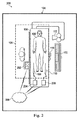
図1は、本開示の一実施態様によるベッド脇インターフェース102を含む医療センシングシステム100を図示した概略図である。一般的に、該医療センシングシステム100は、人の生物学的な生理的及び形態的情報を取得及び解釈ために使用される種々の方法に対して感知的となるように設計された複数の形態の収集及び処理エレメントの一貫性のある統合及び併合を提供する。更に詳細には、システム100において、ベッド脇インターフェース102は、医療センシングデータの収集、制御、解釈、測定及び表示のためのタッチ操作可能な、統合された計算装置である。図示された実施態様において、ベッド脇インターフェース102は、単一面上でユーザ制御及び診断画像を提供するタブレット型のタッチ感知性コンピュータである。当該医療センシングシステム100において、ベッド脇インターフェース102は、複数の医療センシング方式に対応するグラフィックユーザインターフェース(GUI)を介して診断視覚化及び患者画像データを操作することができる。これらのオプションに含まれるものは、ベッド脇インターフェース102の障害箇所の拡大画像を提示し、ユーザに対して一層高いレベルの詳細を提供する能力である。ベッド脇インターフェース102は、図3〜図6に関連して更に詳細に説明する。
FIG. 1 is a schematic diagram illustrating a
図示された実施態様において、当該医療センシングシステム100はカテーテル検査室104内に配備される。カテーテル検査室104は、患者106に対して、これらに限られるものではないが例示として、血管造影法、血管内超音波法(IVUS)、仮想組織診断法(VH)、前方視IVUS(FL-IVUS)、血管内光音響的(IVPA)撮像法、圧力、血流予備量比(FFR)測定、流速、流量、冠状動脈血流予備能(CFR)測定、光干渉断層撮影(OCT)、コンピュータトモグラフィ、心臓内心エコー検査法(ICE)、前方視ICE(FLICE)、血管内パルポグラフィ、経食道心エコー法又は従来技術において既知の何らかの他の医療センシング方式等の任意の多くの医療センシング手順を単独で若しくは組み合わせで実施するために使用することができる。カテーテル検査室104は、インスタント・ウェーブ・フリー・レシオ(登録商標)機能
![]()
![]()
![]()
![]()
図1に示されるように、ベッド脇インターフェース102は無菌野105内に配置することができ、医師107により患者106に対して実行される医療センシング手順又は治療の作業フローを制御するために利用することができる。例えば、医師107は、当該手順の作業フローを開始し、該手順の間において取得される圧力測定値(例えば、圧力波形等の圧力データの視覚的表現)等のリアルタイムな医療センシングデータを監視し、該取得された医療センシングデータに無菌野105の内部のベッド脇インターフェース102を用いて対応することができる。更に、該ベッド脇インターフェースは、ブームディスプレイ122等の他の画像化ツールと一緒に使用することができる。ベッド脇インターフェース102及びブームディスプレイ122は同一の画像を表示することができるか、又はベッド脇インターフェース102は患者を診断し若しくは手術を実行する際に医療専門家を補助すべく代替画像を提供することもできる。例えば、ベッド脇インターフェース102は、他の視角を見せることができるか、又はブームディスプレイ122上に示されたもの上に強調画像を重ねることができる。更に、ベッド脇インターフェース102は、特定の関心領域に対する追加の詳細を提供するために使用することもできる。例えば、医師107はブームディスプレイ122上で全体的診断画像を見る一方、該画像におけるベッド脇インターフェース102上で表示するための一層小さな部分を選択することができる。ベッド脇インターフェース102上の表示の倍率は可変とすることができ、該医師が特定の領域にズームインする一方、全体的画像は依然としてブームディスプレイ122上に見えたままに維持することを可能にする。医師107は、ベッド脇インターフェース102上の斯様な画像を、同時的タッチ入力(即ち、マルチタッチ)及びジェスチャを用いてズームし、回転し、及びそれ以外で操作することができる。他の実施態様において、ベッド脇インターフェース102は、無菌野105外で、例えばカテーテル検査室104内の他の場所で又はカテーテル検査室104に隣接する制御室内で使用することもできる。
As shown in FIG. 1, the bedside interface 102 can be placed in the
図1に示された実施態様において、当該医療センシングシステム100は、医療センシング装置108及び医療センシング装置110並びに処理システム124等の、圧力センシング作業フロー手順を容易化するための当該カテーテル検査室104内の複数の相互接続された医療センシング関連ツールを更に含んでいる。医療センシング装置108及び110は、圧力監視エレメントを含むことができる。医療センシングシステム100の幾つかの実施態様は、医療センシング装置108に通信可能に結合された患者インターフェースモジュール(PIM)112、医療センシング装置110に通信可能に結合されたPIM114、心電図(ECG)装置116、血管造影システム117及びブームディスプレイ122を含むことができる。ベッド脇インターフェース102、PIM112及び114、ECG装置116、血管造影システム117並びにブームディスプレイ122は、処理システム124に通信可能に結合される。幾つかの実施態様において、医療センシング装置108及び110は、撮像作業フローを促進するための撮像エレメントを含むことができる。一実施態様において、処理システム124は医療センシングデータを収集、処理及び表示するためのハードウェア又はソフトウェアによるコンピュータワークステーションであるが、他の実施態様において、該処理システムは医療センシングデータを処理するように動作可能な任意の他のタイプの計算システムとすることができる。例えば、圧力センシング作業フローの間において、処理システム124は、医療センシング装置108及び110並びに/又はPIM112及び114から生の圧力データを受け、該圧力データを例えば圧力波形等の視覚的表現、数値、算出値等を含むスクリーン表示に変換し、該スクリーン表示をベッド脇インターフェース102に対して利用可能にして、これらが分析のために医師107に対して表示され得るようにするよう動作する。処理システム124がコンピュータワークステーションである実施態様において、該システムは、少なくともマイクロインターフェース若しくは専用の中央処理ユニット(CPU)等のプロセッサ、ハードドライブ、ランダムアクセスメモリ(RAM)及び/又はコンパクトディスク読出専用メモリ(CD−ROM)等の非一時的コンピュータ読取可能な記憶媒体、グラフィックス処理ユニット(GPU)等のビデオインターフェース、並びにイーサネット(登録商標)インターフェース等のネットワーク通信装置を含む。
In the embodiment shown in FIG. 1, the
更に、処理システム124はデータネットワーク125に通信可能に結合される。図示された実施態様において、データネットワーク125はTCP/IP型ローカルエリアネットワーク(LAN)であるが、他の実施態様では、同期光ネットワーク(SONET)等の異なるプロトコルを用いることができるか、又は広域ネットワーク(WAN)とすることもできる。この点に関し、ネットワーク125は有線及び/又は無線接続を用いることができる。幾つかの事例において、ネットワーク125の少なくとも一部はセルラネットワークである。当該システム100におけるベッド脇インターフェース102及びブームディスプレイ122等の他の構成部品は処理システム124に有線若しくは無線インターフェースを介して直接的に、又はネットワーク125若しくは他のネットワーク構成部品を介して間接的に接続される。更に、処理システム124はネットワーク125を介して、医療デジタル画像通信(DICOM)システム、画像保存通信システム(PACS)及び病院情報システム等の種々の資源に接続することができる。処理システム124は、2014年6月17日に発行された“MEDICAL MEASURING SYSTEM AND METHOD”なる名称の米国特許第8,754,865号、及び2011年4月8日に出願された“MULTI-MODALITY MEDICAL SENSING SYSTEM AND METHOD”なる名称の米国特許出願第61/473,570号に開示された医療センシングデータを処理する多様式処理システムと同様のものとすることができ、これら両文献は参照により本明細書に全体として組み込まれるものとする。
Further, the processing system 124 is communicably coupled to the data network 125. In the illustrated embodiment, the data network 125 is a TCP / IP type local area network (LAN), but in other embodiments, different protocols such as synchronous optical network (SONET) can be used or wide area. It can also be a network (WAN). In this regard, the network 125 can use wired and / or wireless connections. In some cases, at least part of the network 125 is a cellular network. Other components such as the bedside interface 102 and
医療センシングシステム100において、PIM112及びPIM114は、医療センシング装置108及び医療センシング装置110により患者106から収集された医療センシングデータを各々受信するように動作すると共に、該受信されたデータを処理システム124に送信するように動作する。一実施態様において、PIM112及びPIM114は上記医療センシングデータを周辺機器相互接続エクスプレス(PCIe)データバス接続を介して送信するが、他の実施態様において、これらPIMはデータをUSB接続、サンダーボルト接続、ファイヤワイヤ接続又は何らかの他の高速データバス接続を介して送信することもできる。更に、ECG装置116は心電図信号又は他の血流力学的データを患者106から処理システム124に送信するよう動作する。データキャプチャの際に医師を補助するために、ベッド脇インターフェース102はECGデータを医療センシングデータと一緒に表示するよう動作する。更に、幾つかの実施態様において、処理システム124はカテーテル108及び110によるデータ収集をECG116からのECG信号を用いて同期させるように動作することができる。更に、血管造影システム117は患者106のX線、コンピュータトモグラフィ(CT)又は磁気共鳴画像(MRI)を収集し、これらを処理システム124に送信するように動作する。X線、CT又はMRI画像が処理システム124により人が解読可能な画像へと処理された後、医師107はベッド脇インターフェース102上のGUIを操作して、処理システム124から画像を取り出し、これら画像を該インターフェース上に表示することができる。幾つかの実施態様において、処理システム124は血管造影システム117からの画像データ(例えば、X線データ、MRIデータ、CTデータ等)をカテーテル108及び110からのセンシングデータと重ね合わせることができる。本開示の一態様として、上記重ね合わせは、センシングデータにより三次元画像を発生するために実行することができる。このような重ね合わされた3D画像データはベッド脇インターフェース102上で見ることができる。一実施態様において、医師はベッド脇インターフェース102上の斯様な3D画像を、同時的タッチ入力(即ち、マルチタッチ)及びジェスチャを用いて回転し、ズームし及びそれ以外で操作することができる。
In the
更に、図1の図示された実施態様において、システム100における医療センシングツールは標準の銅線リンク又は光ファイバリンク等の有線接続を介して処理システム124に通信可能に結合される。特に、ベッド脇インターフェース102は、汎用直列バス(USB)接続、パワー・オーバー・イーサネット(登録商標)接続、サンダーボルト接続、ファイヤワイヤ接続又は何らかの他の高速データバス接続を介して処理システム124に通信的に及び/又は電気的に結合することができる。
Further, in the illustrated embodiment of FIG. 1, the medical sensing tool in
しかしながら、図2に示されるもののような他の実施態様において、医療センシングツールは無線で通信することができる。この点に関すると、図2は本開示の他の実施態様による無線ベッド脇インターフェース202を含む医療センシングシステム200を示す概略図である。該医療センシングシステム200は、図1のシステム100に類似するが、無線ベッド脇インターフェース202、無線PIM204及び無線PIM206を含む医療センシングツールは無線ネットワークプロトコルを介して無線ネットワーク208と通信する。例えば、ベッド脇インターフェース202は遠隔処理システムに対してIEEE 802.11Wi-Fi(登録商標)規格、超広帯域(UWB)規格、無線ファイヤワイヤ、無線USB、ブルートゥース(登録商標)又は他の高速無線ネットワーク規格により作業フロー制御パラメータ、医療センシング画像及び測定データを送受することができる。このような無線能力は、医師107が、より良い作業フロー管理のためにベッド脇インターフェース202を無菌野105の内部又は外部に一層自由に配置することを可能にする。
However, in other embodiments such as those shown in FIG. 2, the medical sensing tool can communicate wirelessly. In this regard, FIG. 2 is a schematic diagram showing a medical sensing system 200 including a
次に図3を参照すると、ベッド脇インターフェース202は、把持すると共にカテーテル検査室又は他の環境内であちこち移動させるのが容易な一体的に形成されたハウジング302を有する。一実施態様において、該一体的に形成されたハウジング302は、熱可塑性若しくは熱硬化性プラスチック又は鋳造可能な金属等の材料から継ぎ目無しで型成形することができる。他の実施態様において、該一体的に形成されるハウジング302は、一体的ハウジングを形成するために実質的に永久的に接着固定される複数のハウジング部分を有することもできる。ハウジング302は防液(防水)的であり、一実施態様においては、国際電気標準会議(IEC)により規定された液体の侵入に対するIPX4の等級を有することができる。ハウジング302を異なる環境で使用することができる他の実施態様において、ハブは異なる液体侵入等級を有することができる。図示された実施態様において、ハウジング302は携帯に資する幅、高さ及び厚さを有する。
Next, referring to FIG. 3, the
図3を続いて参照すると、ベッド脇インターフェース202はブームディスプレイ122と関連させて使用するように構成されている。一実施態様において、ベッド脇インターフェース202及びブームディスプレイ122は、血管内センサ及び/又は撮像構成部品により取得されたデータを受信し、対応する医療画像301を表示する。このような画像301は、静止画像、ビデオ、3Dレンダリング、生のセンサ若しくは撮像データ、フィルタ処理されたセンサ若しくは撮像データ、計算されたセンサ若しくは撮像データ、及び/又は当該患者の生体構造を表す他のデータを含むことができる。このデータは、診断手順の間に収集することができるか、又はPCI等の手術手順の間に収集することができる。一実施態様において、診断視覚化情報は、ブームディスプレイ122及び/又はベッド脇インターフェース202上に表示された血管の画像上に重ねられる。これらの診断視覚化情報は、医師107が特定の患者に対して最良の利用可能な治療オプションを決定することを支援することができる。
With reference to FIG. 3, the
上記診断視覚化情報は、マーキング、カラー、数値、又はガイドワイヤ及びカテーテル等の医療器具から得られるデータの他の表現を含むことができる。この点に関して、該診断視覚化情報は、記録された圧力測定値に基づく輝度マップを含むことができると共に、対応する圧力比のグラフを組み込むことができる。更に、該診断視覚化情報は、二次元血管造影画像、三次元血管造影画像及びコンピュータトモグラフィ血管造影(CTA)画像等の血管外画像、並びに超音波(IVUS)画像及び光干渉トモグラフィ(OCT)画像等の血管内画像上に重ねることができる。幾つかの実施態様において、該診断視覚化情報は或るタイプの画像上に重ねられた他のタイプの画像を含むことができる。更に、1以上の治療オプションをシミュレーションすることができると共に、当該診断視覚化情報を各特定のシミュレーションされた治療オプションに関連するパラメータに基づいて更新することができる。このようにして、各治療オプションに関する推定される結果又は成果を当該医師に対して視覚的に提供することができる。上記の診断視覚化及び/又はシミュレーション治療は、2012年8月20日に“DEVICES, SYSTEMS AND METHODS FOR VISUALLY DEPICTING A VESSEL AND EVALUATING TREATMENT OPTIONS”なる名称で出願された国際特許出願公開第2013/028612号、2013年10月25日に“Devices, Systems and Methods for Vessel Assessment”なる名称で出願された米国予備特許出願第61/895,909号、2014年2月21日に“DEVICES, SYSTEMS AND METHODS AND ASSOCIATED DISPLAY SCREENS FOR ASSESSMENT OF VESSELS”なる名称で出願された米国予備特許出願第61/943,168号、及び2014年7月14日に“DEVICES, SYSTEMS AND METHODS FOR TREATMENT OF VESSELS”なる名称で出願された米国予備特許出願第62/024,005号の1以上に記載されているように実施することができ、これら文献の各々は参照により本明細書に全体として組み込まれるものである。 The diagnostic visualization information can include markings, colors, numbers, or other representations of data obtained from medical devices such as guide wires and catheters. In this regard, the diagnostic visualization information can include a brightness map based on the recorded pressure measurements and can incorporate a graph of the corresponding pressure ratio. Further, the diagnostic visualization information includes extravascular images such as two-dimensional angiography images, three-dimensional angiography images and computer tomography angiography (CTA) images, as well as ultrasound (IVUS) images and optical interference tomography (OCT). ) It can be superimposed on an intravascular image such as an image. In some embodiments, the diagnostic visualization information can include other types of images superimposed on one type of image. In addition, one or more treatment options can be simulated and the diagnostic visualization information can be updated based on the parameters associated with each particular simulated treatment option. In this way, presumed results or outcomes for each treatment option can be visually provided to the physician. The above diagnostic visualization and / or simulation treatment was filed on August 20, 2012 under the name "DEVICES, SYSTEMS AND METHODS FOR VISUALLY DEPICTING A VESSEL AND EVALUATING TREATMENT OPTIONS", International Patent Application Publication No. 2013/028612. , US Preliminary Patent Application No. 61 / 895,909 filed under the name “Devices, Systems and Methods for Vessel Assessment” on October 25, 2013, “DEVICES, SYSTEMS AND METHODS AND ASSOCIATED DISPLAY” on February 21, 2014. US Preliminary Patent Application No. 61 / 943,168 filed under the name "SCREENS FOR ASSESSMENT OF VESSELS" and US Preliminary Patent filed under the name "DEVICES, SYSTEMS AND METHODS FOR TREATMENT OF VESSELS" on July 14, 2014. It can be carried out as described in one or more of Japanese Patent Application No. 62 / 024,005, each of which is incorporated herein by reference in its entirety.
上記画像(又は複数の画像)、診断視覚化情報(又は複数の情報)及び/又はシミュレーション治療に基づいて、医師は当該患者に対する最良の治療オプションを決定することができる。医療監督者も、医師107の作業をチェックするため又は患者106にセカンドオピニオンを提供するために、ベッド脇インターフェース202を用いることができる。診断視覚化情報は、医師107が検査結果又は治療オプションを説明するのを支援するために、患者106に又は患者106の介護者に提示することもできる。更に、ベッド脇インターフェース202は、処置の間において治療装置の配置を誘導するために使用することもできる。この場合、医師107はベッド脇インターフェース202を用いて、処置の間における位置的正確さを保証すべく医療器具、ガイドワイヤ又はステントの位置をチェックすることができる。
Based on the image (or images), diagnostic visualization information (or information) and / or simulation treatment, the physician can determine the best treatment option for the patient. The medical supervisor can also use the
医師107が画像301における特定の関心領域をみることを可能にするために、該画像301の一部303がベッド脇インターフェース202上に表示される。ベッド脇インターフェース202はタッチスクリーンインターフェースを備え、医師107が同時的なタッチ入力及びジェスチャを用いて画像301を容易に操作することを可能にする。ベッド脇インターフェース202は、関心領域にズームインし、画像301に関連する画像、グラフィック情報及びテキストを表示することができるように構成される。図3は、全体画像301のうちのベッド脇インターフェース202上に表示される当該ズームイン部分303を示している。図示された実施態様において、通信ネットワーク208はブームディスプレイ122及びベッド脇インターフェース202を処理システム124に接続する。診断処置の間において医師107がベッド脇インターフェース202を望むように運び、再配置し又は動かすことを可能にするために、ベッド脇インターフェース202に対する無線接続が好ましい。この構成は、当該処置の特定の重要な様子を連続的に監視(モニタ)することを可能にすると共に、医師107が診断情報及び治療オプションを他の医師及び/又は当該患者の介護者若しくは家族に通知することを可能にし得る。
A portion 303 of the image 301 is displayed on the
図3に示されるように、ベッド脇インターフェース202は、血管の関心領域に対応する部分303に関する追加の又は一層詳細な診断情報を表示するために使用することもできる。この例において、ブームディスプレイ122は患者の画像301を表示する一方、ベッド脇インターフェース202は関心部分303を診断視覚化情報が重ねられて表示する。図3に示される例においては、当該血管の関心領域に沿ってFFR又はiFR値等の圧力比が示されている。図示のように、当該圧力比には0.92から0.68への大きな低下が存在し、これは深刻な閉塞又は障害を示し得る。任意の多くの他のタイプの診断視覚化情報が上述したように用いることができると理解される。
As shown in FIG. 3, the
更に、1以上の治療オプションをシミュレーションすることができ、ベッド脇インターフェース202上に表示される診断視覚化情報は特定のシミュレーションされた治療オプションに関連するパラメータに基づいて更新することができる。図4は、この手法の一例を示す。特に、図4は、ステント306のシミュレーションされた配置及び当該診断視覚化情報における対応する結果的変化を示している。特に、図3に示された0.68への深刻な低下は、該ステントの配置により0.91の値まで大幅に改善されると推定されている。この及び他の診断視覚化情報による同様の手法を用いて、各治療オプションに関する推定される結果又は成果を、医師に対してベッド脇ディスプレイ202及び/又は頭上ブームディスプレイ122上で視覚的に提供することができる。シミュレーションされた処置をベッド脇インターフェース202上に処置のありそうな結果を示すために表示することができる。シミュレーションされたステント306が、ベッド脇インターフェース202上に、該ステントの寸法及び位置に関する統計的データ303と同様に示される。医師107は、重要な領域を示すか又は進行中の圧力測定値を提供するためにベッド脇インターフェース202の画像301上にマーカ305を配置することもできる。図4に示されたもののようなシミュレーションは、医師107に、ベッド脇インターフェース202上における処置の予測される結果及びブームディスプレイ122上における当該患者のリアルタイム画像301の両方のビューを提供することができ、かくして、治療オプションの詳細で容易に理解可能な分析を提供する。この分析は、患者106又は患者の保護者若しくは介護者とも容易に共有される。
In addition, one or more treatment options can be simulated and the diagnostic visualization information displayed on the
図5は、本開示の態様によるベッド脇コントローラ300の機能ブロック図を示す。ハウジング302の前部に埋め込まれるものは接触感知性ディスプレイ307であり、該ディスプレイはタッチパネル308及びフラットパネルディスプレイ309を有している。タッチパネル308はフラットパネルディスプレイ309上に重なり、人の接触、スタイラスの接触又は他の同様の入力方法を介してユーザ入力を受ける。言い換えると、接触感知性ディスプレイ307は、同一面上で画像を表示すると共にユーザ入力を受ける。本実施態様において、タッチパネル308は抵抗型パネルであるが、他の実施態様において、該タッチパネルは容量型パネル、投影型パネル又は何らかの他の好適なタイプの接触可能化入力パネルとすることもできる。更に、タッチパネル308は、例えば血管の三次元レンダリングの複数の軸に沿う回転を可能にするために、複数の入力を同時に受けるよう動作することができる(マルチタッチ)。更に、タッチパネル308は、滅菌ドレープがベッド脇インターフェース300を覆っている場合、及びユーザが手袋をはめている場合にも、入力を受けることができる。タッチパネル308は、ハウジング302内に配置されたタッチインターフェース310により制御される。更に、医師がタッチパネル308に接触した場合、該タッチパネルは触覚インターフェース312及び触覚ドライバ314を介して触覚フィードバックを供給するよう動作することができる。この触覚技術は、ユーザが当該タッチパネルに接触した場合に発生される振動の強度及び周波数を変化させることによりタッチパネル308上での複数の感覚をシミュレーションするように動作することができる。幾つかの実施態様において、ハウジング302は、内部にスタイラスを保管するよう構成された鞘を有することができる。このように、医師は、当該ベッド脇インターフェースで測定を行うために上記ハウジング内の鞘からスタイラスを取り出す一方、測定が完了した場合に該スタイラスを保管することができる。
FIG. 5 shows a functional block diagram of the
タッチパネル308の下には、ユーザに対してグラフィックユーザインターフェース(GUI)316を提供するフラットパネルディスプレイ309が存在する。図示された実施態様において、該フラットパネルディスプレイ309はLCDディスプレイであるが、他の実施態様において、該フラットパネルディスプレイはLEDディスプレイ又はAMOLEDディスプレイ等の別のタイプのディスプレイとすることもできる。図示の実施態様において、フラットパネルディスプレイ309はLEDバックライト電力インバータ318により照明される。上述したように、GUI316は、医師が医療センシング作業フローを制御することを可能にするのみならず、無菌野内の患者から得られる圧力データを見ると共に該データと対話することも可能にする。
Below the touch panel 308 is a flat panel display 309 that provides the user with a graphic user interface (GUI) 316. In the illustrated embodiment, the flat panel display 309 is an LCD display, but in other embodiments, the flat panel display can be another type of display, such as an LED display or an AMOLED display. In the illustrated embodiment, the flat panel display 309 is illuminated by the LED backlit
ベッド脇インターフェース300は、ハウジング302内に単一基板処理プラットフォーム320を含み、該処理プラットフォームはGUI316をレンダリングすると共にユーザタッチ入力を処理するように動作することができる。図示の実施態様において、当該処理プラットフォームはピコフォームファクタを有し、プロセッサ321、システムメモリ322、グラフィックス処理ユニット(GPU)、通信モジュール323及びI/Oバスインターフェース等の統合された処理構成部品を含んでいる。幾つかの実施態様において、プロセッサ321はインテル社製アトム(Atom:登録商標)プロセッサ又はARMベースのプロセッサ等の低電力プロセッサとすることができ、通信モジュール323は10/100/1Gbのイーサネット(登録商標)モジュールとすることができる。上記I/Oバスインターフェースは汎用直列バス(USB)インターフェースであり得る。ベッド脇インターフェース300は更に記憶モジュール324も含み、該記憶モジュールはオペレーティングシステム(即ち、GUIをレンダリング及び制御するためのソフトウェア)、データ及び/又は視覚表現操作ソフトウェア、処理システムから受信される医療センシングデータ及び視覚表現、並びに他の医療センシング関係ソフトウェアを記憶するように動作することができる非一時的コンピュータ読取可能な記憶媒体である。プロセッサ321は記憶モジュール324上に記憶されたソフトウェア及び命令を実行するように構成される。図示の実施態様において、記憶モジュール324はSATA接続を介して処理プラットフォーム320に通信可能に結合された固体ドライブ(SSD)型ハードドライブであるが、他の実施態様において、該記憶モジュールは任意の他のタイプの不揮発性又は一時的記憶モジュールとすることができる。ベッド脇インターフェース300は、更に、処理プラットフォーム320に通信可能に結合された無線通信モジュール326を含む。幾つかの実施態様において、該無線通信モジュールはIEEE 802.11Wi-Fi(登録商標)モジュールであるが、他の実施態様では、超広帯域(UWB)無線モジュール、無線ワイヤファイヤモジュール、無線USBモジュール、ブルートゥース(登録商標)モジュール又は他の高速無線ネットワークモジュールとすることもできる。
The
図示の実施態様において、ベッド脇インターフェース300は結線される12VDCパワー・オーバー・イーサネット(登録商標)(PoE)接続328及びハウジング302内に配置された電池330の両方を介して給電される。一実施態様において、電池330は一体的に形成されるハウジング302内に密閉することができ、該ハウジングの外部に配置されると共に当該電池に電気的に結合された電気接点を介して再充電することができる。図5の実施態様に示されるように、前壁350は、当該インターフェースが互換性のある充電構造を備える対象に取り付けられた場合に該電池330を充電することができる1以上の電気接点358を含むことができる。他の実施態様において、ハウジング302は電池交換を可能にするための取り外し可能なカバーを備えた電池室を含むことができる。このような電池室カバーは流体の侵入に耐性のあるものとすることができる(例えば、IPX4等級を持つ)。ベッド脇インターフェース300はカテーテル検査室内の処理システムにPoE接続328を介して結合することができ、当該ベッド脇インターフェースは該PoE接続を介して、患者からキャプチャされ当該処理システム上にレンダリングされる医療センシングデータを受信する。動作時において、当該ベッド脇インターフェースがPoE接続328に結合されると、該ベッド脇インターフェースは電力及び通信を同じ物理的ワイヤを介して受ける。ベッド脇インターフェース300がPoE接続328から切り離された場合、該ベッド脇インターフェースは電池の電力で動作し、無線通信モジュール326を介してデータを無線で受信する。カテーテル検査室において無線で使用される場合、当該ベッド脇インターフェースは処理システムと直接通信することができるか(即ち、アドホック無線モードで)、又は代わりに複数の無線装置にサービスする無線ネットワークと通信することができる。他の実施態様において、ベッド脇インターフェース300は電力及びデータを異なる有線接続を介して受けることができるか、有線データ接続を介してデータ通信を受信すると共に電池330から電力を受けることができるか、又は無線モジュール326を介してデータ通信を受信すると共に有線電気接続から電力を受けることができる。幾つかの実施態様において、ベッド脇インターフェース300は準無線(semi-wireless)構成で使用することもでき、該構成において電池330は当該インターフェースが有線電源から一時的に切断されている場合に該インターフェースにバックアップ電力を供給する。例えば、処置の開始時にベッド脇インターフェース300がPoE接続(又は他のタイプの有線接続)に接続され、当該処置の間において配線の調整を可能にするために該インターフェースをPoE接続から切断しなければならない場合、電池330はPoE接続が再確立されるまで当該インターフェースを動作状態に維持することができる。このようにして、処置の間においてインターフェース300の完全な電源オフ及び再ブートが回避される。図5に示されるように、DC/DC電力コンバータ332は入力電圧を処理プラットフォーム320により使用可能な電圧に変換する。
In the illustrated embodiment, the
ベッド脇インターフェース300は、ここに述べた特定の構成部品を有するが、該ベッド脇インターフェースは例えば前記電気接点と電池との間に配置された充電調整器等の任意の多くの追加の構成部品を含むことができ、代替実施態様においては任意の多くの代替的配置で構成することができると理解される。
The
図6は、患者の治療を計画する方法600を解説したフローチャートである。方法600は、iFR手順等の圧力センシング手順の前後関係で説明されるが、FFR手順、IVUS手順、OCT手順、FLIVUS手順及びICE手順等の任意の多くの医療センシング又は治療手順に等しく当てはまり得るものである。方法600は図7〜図10を参照すると一層良く理解することができる。
FIG. 6 is a flowchart illustrating a
この点に関して、図7及び図8を参照すると、本開示の一実施態様による狭窄を有する導管800が図示されている。この点に関し、図7は導管800の概略斜視図である一方、図8は導管800の一部の部分断面斜視図である。図7を詳細に参照すると、導管800は近端部802及び遠端部804を含んでいる。管腔806が、導管800の長さに沿って近端部802と遠端部804との間に延びている。この点に関し、管腔806は当該導管を経て流体の流れを可能にするようになっている。幾つかの事例において、導管800は血管である。幾つかの特定の事例において、血管800は環状動脈である。このような事例において、管腔806は血管800を介しての血液の流れを容易にするようになっている。
In this regard, with reference to FIGS. 7 and 8,
図示されたように、血管800は近端部802と遠端部804との間に狭窄808を含んでいる。狭窄808は、一般的に、血管800の管腔806を介しての流体の流れの制限を生じる何らかの閉塞又は他の構造的状態を表す。本開示の実施態様は、限定するものではないが環状動脈、末梢血管(限定するものではないが、下肢、頸動脈及び神経血管を含む)、腎臓及び/又は静脈を含む広範囲の血管応用分野における使用に適している。導管800が血管である場合、狭窄808は、限定されるものではないが、繊維質、繊維状脂質(繊維状脂肪)、壊死性コア、石灰化(濃密カルシウム)、血液、新鮮血栓及び成熟血栓を含むプラーク蓄積の結果であり得る。一般的に、狭窄の組成は評価されている血管のタイプに依存する。この点に関して、本開示の思想は、流体の流れの減少を生じる導管の実質的に如何なるタイプの閉塞又は狭窄にも適用可能であると理解される。
As shown, the
図8を更に詳細に参照すると、血管800の管腔806は狭窄808の近端側で直径810を、該狭窄の遠端側で直径812を有している。幾つかの事例において、直径810及び812は実質的に互いに等しい。この点に関し、直径810及び812は狭窄808と比較して当該管腔806の健康な部分又は少なくとも一層健康な部分を表そうとするものである。従って、管腔806の斯かる一層健康な部分は、実質的に一定な円柱状外形を有するように図示されており、結果として該管腔の高さ又は幅は直径と称される。しかしながら、多くの事例において、管腔806の斯かる部分は狭窄808よりも少ない程度ではあるがプラークの蓄積、非対称な外形及び/又は他の不規則さも有する(従って、円柱状外形は有さない)と理解される。このような事例において、上記直径810及び812は、当該管腔の相対寸法又は断面積を表し、円形断面形状を意味するものではないと理解される。
With reference to FIG. 8 in more detail, the lumen 806 of the
図8に示されるように、狭窄808は血管800の管腔806を狭めるプラーク蓄積814を含んでいる。幾つかの事例において、プラーク蓄積814は一様な又は対称な外形は有さず、このような狭窄の血管造影評価を信頼のおけないものにさせる。図示された実施態様において、プラーク蓄積814は上側部分816及び対向する下側部分818を有している。この点に関し、下側部分818は上側部分816に対して大きな厚さを有し、その結果、当該管腔における狭窄808の近端側及び遠端側の部分に対して非対称で不均一な外形を生じる。図示されたように、プラーク蓄積814は流体が管腔806を介して流れるために利用可能な空間を減少させる。特に、管腔806の断面積が該プラーク蓄積814により減少される。上側及び下側部分816及び818の間の最も狭い箇所において、管腔806は高さ820を有し、該高さは狭窄808より近端側及び遠端側の直径810及び812に対して減少された寸法又は断面積を表す。プラーク蓄積814を含む狭窄808は、性質的に例示的なもので、何らかの態様で制限するものであると考えられるべきものであることに注意されたい。この点に関し、狭窄808は他の事例においては管腔806を経る流体の流れを制限するような他の形状及び/又は組成を有すると理解される。血管800は図7及び図8においては単一の狭窄808を有するものとして図示され、以下の実施態様の説明は主に単一の狭窄に関連してなされるが、ここに記載される装置、システム及び方法は複数の狭窄領域を有する血管に対しても同様の応用性を有すると理解される。
As shown in FIG. 8, the
ここで図9を参照すると、血管800は、本開示の一実施態様により器具830及び832が内部に配置されて図示されている。一般的に、器具830及び832は、血管内に配置されるように寸法決め及び形成された如何なる形態の装置、器具又はプローブとすることもできる。器具830及び832は、当該医療センシングシステム100(図1)において医療センシング装置108及び110として構成することができる。図示の実施態様において、器具830は概してガイドワイヤを表す一方、器具832は概してカテーテルを表している。この点に関し、器具830は器具832の中心管腔を介して延在する。しかしながら、他の実施態様において、器具830及び832は他の形態を呈することもできる。この点に関し、器具830及び832は幾つかの実施態様では同様の形態のものである。例えば、幾つかの事例において、両器具830及び832はガイドワイヤである。他の事例において、両器具830及び832はカテーテルである。一方、器具830及び832は、図示された実施態様のような幾つかの実施態様では異なる形態のものであり、これら器具のうちの一方はカテーテルであり、他方はガイドワイヤである。更に、幾つかの事例において、器具830及び832は、図9の図示の実施態様に示されるように、互いに同軸的に配置される。他の実施態様において、これら器具のうちの一方は、他方の器具の心の外れた管腔を介して延在する。更に他の事例において、器具830及び832は並んで延在する。幾つかの特定の実施態様において、これら器具のうちの少なくとも1つは、迅速交換カテーテルのような迅速交換装置である。このような実施態様において、他方の器具は、バディワイヤ又は当該迅速交換装置の導入及び除去を容易化するように構成された他の装置である。更に、他の事例においては、2つの別個の器具830及び832の代わりに、単一の器具が使用される。幾つかの実施態様において、該単一の器具は、両器具830及び832の機能の特徴(例えば、データ収集)を組み込む。
Here, with reference to FIG. 9, the
器具830は、血管800に関する診断情報を取得するように構成される。この点に関し、器具830は血管に関する診断情報を取得するための1以上のセンサ、トランスジューサ及び/又は他の監視エレメントを含む。上記診断情報は、圧力、フロー(速度及び/又は量)、画像(超音波(例えば、IVUS)、OCT、熱及び/又は他の撮像技術を用いて取得される画像を含む)、温度、及び/又はこれらの組み合わせのうちの1以上を含む。上記1以上のセンサ、トランスジューサ及び/又は他の監視エレメントは、幾つかの事例では器具830の遠端部に隣接して配置される。この点に関し、該1以上のセンサ、トランスジューサ及び/又は他の監視エレメントは、幾つかの事例では器具830の遠端側先端834から30cm未満、10cm未満、5cm未満、3cm未満、2cm未満及び/又は1cm未満に配置される。幾つかの事例において、上記1以上のセンサ、トランスジューサ及び/又は他の監視エレメントのうちの少なくとも1つは器具830の遠端側先端に配置される。
Instrument 830 is configured to acquire diagnostic information about
器具830は、血管800内の圧力をモニタするように構成された少なくとも1つのエレメントを含む。該圧力監視エレメントは、ピエゾ抵抗圧力センサ、圧電(ピエゾ)圧力センサ、容量性圧力センサ、電磁圧力センサ、液柱(該液柱は、当該器具とは別体である液柱センサに連通する、及び/又は該器具の当該液柱の近端側の部分に配置される)、光学圧力センサ、及び/又はこれらの組み合わせの形態をとることができる。幾つかの事例において、該圧力監視エレメントの1以上の特徴は、半導体及び/又は他の好適な製造技術を用いて製造される固体部品として実施化される。適切な圧力監視エレメントを含む市場で入手可能なガイドワイヤ製品の例は、限定されるものではないが、Volcano Corporationから各々入手可能なPrimeWire PRESTIGE(R)圧力ガイドワイヤ、PrimeWire(R)圧力ガイドワイヤ及びComboWire(R)XT圧力及びフローガイドワイヤ、並びにSt.Jude Medical,Inc.から各々入手可能なPressureWireTM Certusガイドワイヤ及びPressureWireTM Aerisガイドワイヤを含む。一般的に、器具830は、遠端側の圧力測定値(読み)に影響を与え得るような当該狭窄の間の流体の流れに大きな影響を与えることなく該狭窄808を経て配置することができるように寸法決めされる。従って、幾つかの事例において器具830は0.014インチ以下の直径を有する。
Instrument 830 includes at least one element configured to monitor pressure within
器具832も、血管800に関する診断情報を得るように構成される。幾つかの事例において、器具832は器具830と同一の診断情報を得るように構成される。他の事例において、器具832は器具830とは異なる診断情報を得るように構成され、該異なる診断情報は、追加の診断情報、より少ない診断情報及び/又は他の診断情報を含み得る。器具832により取得される診断情報は、圧力、フロー(速度及び/又は量)、画像(超音波(例えば、IVUS)、OCT、熱及び/又は他の撮像技術を用いて取得される画像を含む)、温度、及び/又はこれらの組み合わせのうちの1以上を含む。この点に関し、上記1以上のセンサ、トランスジューサ及び/又は他の監視エレメントは、幾つかの事例では器具832の遠端部に隣接して配置される。この点に関し、該1以上のセンサ、トランスジューサ及び/又は他の監視エレメントは、幾つかの事例では器具832の遠端側先端836から30cm未満、10cm未満、5cm未満、3cm未満、2cm未満及び/又は1cm未満に配置される。幾つかの事例において、上記1以上のセンサ、トランスジューサ及び/又は他の監視エレメントのうちの少なくとも1つは器具832の遠端側先端に配置される。
Instrument 832 is also configured to obtain diagnostic information about
器具830と同様に、器具832も、血管800内の圧力をモニタするように構成された少なくとも1つのエレメントを含む。該圧力監視エレメントは、ピエゾ抵抗圧力センサ、圧電圧力センサ、容量性圧力センサ、電磁圧力センサ、液柱(該液柱は、当該器具とは別体である液柱センサに連通する、及び/又は該器具の当該液柱の近端側の部分に配置される)、光学圧力センサ、及び/又はこれらの組み合わせの形態をとることができる。幾つかの事例において、該圧力監視エレメントの1以上の特徴は、半導体及び/又は他の好適な製造技術を用いて製造される固体部品として実施化される。幾つかの事例では、Siemens AXIOM Sensis、Mennen Horizon XVu及びPhilips Xper IM Physiomonitoring 5の1以上と一緒に使用するのに適し、圧力監視エレメントを含む現在入手可能なカテーテル製品を器具832のために用いることができる。
Like the instrument 830, the instrument 832 also includes at least one element configured to monitor the pressure in the
本開示の態様によれば、器具830及び832のうちの少なくとも1つは血管800内の狭窄808の遠端側の圧力をモニタするように構成され、器具830及び832のうちの少なくとも1つは該血管内の当該狭窄の近端側の圧力をモニタするように構成される。この点に関し、器具830、832は、血管800内の圧力をモニタするように構成された上記少なくとも1つのエレメントの配置が当該装置の構成に基づき必要に応じて狭窄808の近端側及び/又は遠端側に位置決めされることを可能にするように寸法決めされると共に成形される。この点に関し、図9は狭窄808の遠端側の圧力を測定するのに適した位置838を示している。この点に関し、該位置838は、幾つかの事例では、狭窄808の遠端(図8に示されるような)から5cm未満、3cm未満、2cm未満、1cm未満、5mm未満及び/又は2.5mm未満である。図9は、狭窄808の近端側の圧力を測定するための複数の好適な位置も示している。この点に関し、幾つかの事例において、位置840、842、844、846及び848は、各々、当該狭窄の近端側の圧力をモニタするのに適した位置を表している。この点に関し、位置840、842、844、846及び848は、狭窄808の近端から20cm以上から約5mm以下までの範囲の種々の距離に配置されている。一般的に、近端側圧力測定は当該狭窄の近端から離隔されてなされる。従って、幾つかの事例において、近端側圧力測定値は、当該狭窄の近端から、血管の管腔の内径以上の距離においてとられる。環状動脈圧力測定の前後関係において、近端側圧力測定値は、一般的に、当該血管の近端側部分における当該狭窄の近端側で大動脈の遠端側の位置においてとられる。しかしながら、環状動脈圧力測定の幾つかの特定の事例において、近端側圧力測定値は大動脈内の位置からとられる。他の事例において、近端側圧力測定値は冠状動脈の根元又は口においてとられる。
According to aspects of the present disclosure, at least one of the instruments 830 and 832 is configured to monitor the pressure on the far end side of the
幾つかの実施態様において、器具830及び832のうちの少なくとも一方は、管腔806を経て移動されている間に血管800内の圧力をモニタするように構成される。幾つかの事例において、器具830は管腔806を経て且つ狭窄808を超えて移動されるように構成される。この点に関し、器具830は、幾つかの事例において、狭窄808の遠端側に位置決めされると共に該狭窄を横切って該狭窄の近端側の位置へと近端側方向に移動される(即ち、引き戻される)。他の事例において、器具830は狭窄808の近端側に位置決めされると共に該狭窄を横切って該狭窄の遠端側の位置へと遠端側方向に移動される。幾つかの実施態様において、近端側方向又は遠端側方向の何れの方向への器具830の移動も医療要員により手作業(例えば、手術医の手)で制御される。他の実施態様において、近端側方向又は遠端側方向の何れの方向への器具830の移動も、移動制御装置(例えば、Volcano Corporationから入手可能なTrak Back(R) II Device等の引き抜き装置)により自動的に制御される。この点に関し、上記移動制御装置は、幾つかの事例では、器具830の移動を選択可能で既知の速度(例えば、2.0mm/s、1.0mm/s、0.5mm/s、0.2mm/s等)で制御する。血管を経ての器具830の移動は、幾つかの事例では、各引き抜き又は押し通しに対して連続的である。他の事例において、器具830は血管を経てステップ状に移動される(即ち、一定量の距離及び/又は一定量の時間で繰り返し移動される)。以下に説明する視覚的描写の幾つかの特徴は、器具830及び832のうちの少なくとも一方が管腔806を介して移動される実施態様に対し特に適している。更に、幾つかの特定の事例において、以下に説明する視覚的描写の特徴は、単一の器具が第2の器具の存在を伴って又は伴わずに、管腔806を介して移動されるような実施態様にとり特に適している。
In some embodiments, at least one of the instruments 830 and 832 is configured to monitor pressure within the
幾つかの事例において、単一の器具の使用は、或る器具の圧力測定値の他方のものに対する時間にわたる変動(通常、ドリフトと称される)に関連する問題を回避するという点で利点を有している。この点に関し、伝統的な血流予備量比(FFR)測定値のドリフトの主たる原因は、ガイドカテーテルの圧力測定値に対するガイドワイヤの圧力測定値の発散である。この点に関し、FFRは当該カテーテルにより取得された圧力測定値に対する当該ガイドワイヤにより取得された圧力測定値の比として計算されるので、この発散は結果としてのFFR値に対して影響を有する。対照的に、単一の器具が当該血管を経て移動される間に圧力測定値を取得するために用いられる場合、ドリフトは無視可能であるか又は存在しない。例えば、幾つかの事例においては、単一の器具が、各圧力測定の間の期間が該器具の圧力感度の如何なる変化からの影響も回避するほど十分に短くなるようにして(例えば、500ms未満、100ms未満、50ms未満、10ms未満、5ms未満、1ms未満、又はそれ以外)、当該血管を経て移動される際に圧力の相対的変化を取得するために使用される。 In some cases, the use of a single instrument has the advantage of avoiding problems associated with time-dependent fluctuations (commonly referred to as drift) of one instrument's pressure readings to the other. Have. In this regard, the main cause of drift in traditional blood flow reserve ratio (FFR) measurements is the divergence of the guidewire pressure measurements relative to the guide catheter pressure measurements. In this regard, this divergence has an effect on the resulting FFR value, as the FFR is calculated as the ratio of the pressure measurement obtained by the catheter to the pressure measurement obtained by the guidewire. In contrast, if a single instrument is used to obtain pressure measurements while moving through the vessel, drift is negligible or absent. For example, in some cases, a single instrument ensures that the period between each pressure measurement is short enough to avoid the effects of any change in the pressure sensitivity of the instrument (eg, less than 500 ms). , Less than 100 ms, less than 50 ms, less than 10 ms, less than 5 ms, less than 1 ms, or otherwise), used to obtain relative changes in pressure as it travels through the vessel.
ここで図10を参照すると、該図には本開示の一実施態様によるシステム850が示されている。この点に関し、図10はシステム850の図式的概略図である。幾つかの実施態様において、システム850は医療センシングシステム100(図1)として実施化することができる。幾つかの実施態様において、該システム850では、接触感知性ディスプレイを有するベッド脇インターフェースのような医療センシングシステム100の1以上の構成部品を付加的に実施化することができる。図示されたように、システム850は器具852を含んでいる。この点に関し、幾つかの事例において、器具852は前述した器具830及び832(図7〜図9)並びに/又は医療センシング装置108及び110(図1)のうちの少なくとも1つとして使用するのに適したものである。従って、幾つかの事例において、器具852は、幾つかの事例において器具830及び832に関して前述したものと同様のフィーチャを含んでいる。図示した実施態様において、器具852は遠端部854及び該遠端部に隣接して配置されたハウジング856を有するガイドワイヤである。この点に関し、ハウジング856は当該器具852の遠端側先端から約3cm隔てられている。該ハウジング856は、当該血管に関する診断情報を得るための1以上のセンサ、トランスジューサ及び/又は他の監視エレメントを収容するように構成されている。図示された実施態様において、ハウジング856は、当該器具852が配置される管腔内の圧力をモニタするように構成された少なくとも1つの圧力センサを収容する。シャフト858が、該ハウジング856から近端側に延びている。トルク装置860が、シャフト858の近端部上に配置されると共に該近端部に結合されている。当該器具852の近端部862は、コネクタ864に結合されている。ケーブル866が、該コネクタ864からコネクタ868まで延びている。幾つかの事例において、コネクタ868はインターフェース870にプラグ接続されるように構成される。この点に関し、インターフェース870は幾つかの事例では患者インターフェースモジュール(PIM)である。該インターフェース870は、前記PIM112(図1)として実施化することができる。幾つかの事例において、ケーブル866は無線接続に置換される。この点に関し、物理的接続(電気的、光学的及び/又は流体的接続を含む)、無線接続及び/又はこれらの組み合わせを含む、器具852とインターフェース870との間の種々の通信経路を利用することができると理解される。
With reference to FIG. 10, the figure shows the
インターフェース870は、接続874を介して計算装置872に通信的に結合される。計算装置872は、一般的に、本開示内で述べられる処理及び分析技術を実行するのに適した任意の装置を表すものである。幾つかの実施態様において、計算装置872はプロセッサ、ランダムアクセスメモリ及び記憶媒体を含む。この点に関し、幾つかの特定の事例において、該計算装置872は、ここで説明されるデータ収集及び分析に関連するステップを実行するようにプログラムされる。従って、本開示のデータ収集、データ処理、器具制御及び/又は他の処理若しくは制御態様に関連する如何なるステップも、上記計算装置により、該計算装置によりアクセス可能な非一時的コンピュータ読取可能な媒体に記憶された対応する命令を用いて実施することができると理解される。幾つかの事例において、計算装置872は前記ベッド脇インターフェースである。例えば、ここに述べる処理ステップは、前記処理プラットフォーム320等の、当該ベッド脇インターフェースの1以上の処理要素により実行することができる。幾つかの事例において、計算装置872はコンソール装置である。幾つかの特定の事例において、計算装置872は、各々Volcano Corporationから入手可能な、s5TM Imaging System又はs5iTM Imaging Systemに類似のものである。幾つかの事例において、計算装置872は可搬型のもの(例えば、手持ち型、手押しカート上、等)である。更に、幾つかの事例において、計算装置872は複数の計算装置を有するものと理解される。この点に関し、本開示の異なる処理及び/又は制御態様は、特に、複数の計算装置を用いて別個に又は予め定められたグループ内で実施することができると理解される。下記に述べる複数の計算装置にまたがる処理及び/又は制御態様の任意の分割及び/又は組み合わせも、本開示の範囲内である。
コネクタ864、ケーブル866、コネクタ868、インターフェース870及び接続874は、一緒になって、器具852の1以上のセンサ、トランスジューサ及び/又は他の監視エレメントと、計算装置872との間の通信を容易にする。しかしながら、この通信経路は性質上例示的なもので、決して制限するものと見なしてはならない。この点に関し、物理的接続(電気的、光学的及び/又は流体的接続を含む)、無線接続及び/又はこれらの組み合わせを含み、器具852と計算装置872との間の如何なる通信経路も利用することができると理解される。この点に関し、接続874は幾つかの事例では無線であると理解される。幾つかの事例において、接続874はネットワーク(例えば、イントラネット、インターネット、通信ネットワーク及び/又は他のネットワーク)上の通信リンクを含む。この点に関し、幾つかの事例において、計算装置872は器具852が使用されている手術領域から遠方に配置されると理解される。接続874にネットワーク上の接続を含ませることは、器具852と遠隔の計算装置872との間の通信を、該計算装置が隣接する部屋、隣接するビル内にあるか又は別の州/国にあるかに無関係に容易化することができる。更に、幾つかの事例において、器具852と計算装置872との間の通信経路は安全な接続であると理解される。更に、幾つかの事例において、器具852と計算装置872との間の通信経路の1以上の位置にわたって通信されるデータは暗号化されると理解される。
The
当該システム850は器具875も含む。この点に関し、幾つかの事例において、器具875は前述した器具830及び832(図7〜図9)並びに/又は医療センシング装置108及び110(図1)のうちの少なくとも1つとして使用するのに適したものである。従って、幾つかの事例において、器具875は、幾つかの事例において器具830及び832に関して前述したものと同様のフィーチャを含んでいる。図示した実施態様において、器具875はカテーテル型装置である。この点に関し、器具875は、血管に関する診断情報を取得するように構成された、該器具の遠端部に隣接する1以上のセンサ、トランスジューサ及び/又は他の監視エレメントを含む。図示の実施態様において、器具875は、該器具875が位置された管腔内の圧力をモニタするよう構成された圧力センサを含む。該器具875は、接続877を介してインターフェース876と通信する。幾つかの事例において、インターフェース876は、Siemens AXIOM Sensis、Mennen Horizon XVu及びPhilips Xper IM Physiomonitoring 5等の、血行動態監視システム又は他の制御装置である。或る特定の実施態様において、器具875は、長さに沿って延在する液柱を含んだ圧力感知性カテーテルである。このような実施態様において、インターフェース876は、当該カテーテルの上記液柱に流体的に結合された止血弁、該止血弁に流体的に結合されたマニホルド、及び斯かる部品を流体的に結合するために該部品間に必要に応じて延びる配管を含む。この点に関し、当該カテーテルの液柱は、上記弁、マニホルド及び配管を介して圧力センサに流体的に連通する。幾つかの事例において、該圧力センサはインターフェース876の一部である。他の事例において、該圧力センサは器具875とインターフェース876との間に配置される別個の部品である。インターフェース876は接続878を介して計算装置872と通信的に結合される。
The
器具852と計算装置872との間の接続と同様に、インターフェース876並びに接続877及び878は、器具875の1以上のセンサ、トランスジューサ及び/又は他の監視エレメントと、計算装置872との間の通信を容易にする。しかしながら、この通信経路は性質上例示的なもので、決して制限するものと見なしてはならない。この点に関し、物理的接続(電気的、光学的及び/又は流体的接続を含む)、無線接続及び/又はこれらの組み合わせを含み、器具875と計算装置872との間の如何なる通信経路も利用することができると理解される。この点に関し、接続878は幾つかの事例では無線であると理解される。幾つかの事例において、接続878はネットワーク(例えば、イントラネット、インターネット、通信ネットワーク及び/又は他のネットワーク)上の通信リンクを含む。この点に関し、幾つかの事例では、計算装置872は器具875が使用されている手術領域から遠方に配置されると理解される。接続878にネットワーク上の接続を含ませることは、器具875と遠隔の計算装置872との間の通信を、該計算装置が隣接する部屋、隣接するビル又は別の州/国にあるかに無関係に容易化することができる。更に、幾つかの事例において、器具875と計算装置872との間の通信経路は安全な接続であると理解される。更に、幾つかの事例において、器具875と計算装置872との間の通信経路の1以上の位置にわたって通信されるデータは暗号化されると理解される。
Similar to the connection between
当該システム850の1以上の構成部品は本開示の他の実施態様では、含まれず、異なる配置/順序で実施化され、及び/又は代替装置/機構により置換されると理解される。例えば、幾つかの事例において、システム850はインターフェース870及び/又はインターフェース876を含まない。このような事例において、コネクタ868(又は、器具852又は器具875につながる他の同様のコネクタ)は、計算装置872に関連するポートにプラグ接続することができる。代わりに、器具852、875は計算装置872と無線で通信することもできる。一般的に言うと、器具852、875の一方又は両方と、計算装置872との間の通信経路は、中間ノードを有さない(即ち、直結)、当該器具と計算装置との間に1つの中間ノードを有する、又は当該器具と計算装置との間に複数の中間ノードを有することができる。システム850は、更に、医療センシングシステム100(図1)のベッド脇インターフェースのような、ベッド脇インターフェースを含むことができる。該ベッド脇インターフェースは、医師により器具852及び875を制御して、処置の間に圧力データを収集し、リアルタイムな医療圧力測定値(例えば、圧力波形、数値等の圧力データの視覚的表現)を監視し、該ベッド脇インターフェースを用いて取得された医療センシングデータと対話するために使用することができる。この点に関し、該ベッド脇インターフェースは計算装置872、インターフェース870及び876、並びに/又は器具852及び875と通信可能に結合することができる。
It is understood that one or more components of the
図6を再び参照すると、方法600はブロック610で開始し、該ブロックにおいては器具830及び832等の診断器具を用いて圧力測定値が取得される。これら診断器具は、血管800に関する診断情報も取得するように構成される。一実施態様において、これら器具830及び832は、血管800内の圧力をモニタするように構成された前記1以上のエレメントの配置が、当該装置の構成に基づいて必要に応じて狭窄808の近端側及び/又は遠端側に位置決めされることを可能にするように寸法決め及び成形される。この器具には、ピエゾ抵抗圧力センサ、圧電圧力センサ、容量性圧力センサ、電磁圧力センサ、液柱、光学圧力センサ及び/又はこれらの組み合わせ等の、種々のセンサを組み込むことができる。
With reference to FIG. 6 again,
ブロック620において、上記圧力測定データは処理システムに伝送される。この処理システムは計算装置872の形態をとることができる。幾つかの実施態様において、当該圧力測定データはPIM112又はインターフェース870に直接伝送することができる。該データの伝送は、有線接続(ケーブル866を用いた)又は無線接続を介して達成することができる。この点に関し、当該処理システムは当該診断器具が使用されている手術領域から遠くに配置することができる。接続874にネットワークを介してノードの接続を含ませることは、当該診断器具と当該処理システムとの間の通信を、当該計算装置が隣接する部屋、隣接するビル又は別の州/国にあるかに無関係に容易化することができる。典型的な実施態様において、処理システムは、当該診断器具から生の圧力データを収集し、該データを処理して、取得された圧力データの視覚的表現をレンダリングすることができる。
At
ブロック630において、医療画像の表示を容易化するために、データはブームディスプレイ122及びベッド脇インターフェース202に伝送される。この医療画像は、診断的視覚化とすることができ、数値の、グラフィックの、テキストの及び/又は他の適切な視覚化を含むことができる。ベッド脇インターフェース202及びブームディスプレイ122は上記視覚的表現を当該処理システムから取り込み、これらをユーザに対してリアルタイムに表示する。前述したように、PIM112又はインターフェース870は、診断表示を医師107又は患者106に対して表示するためにベッド脇インターフェース202と一緒に使用することができる。ブロック640において、ベッド脇インターフェース202はクローズアップ関心領域を表示するために使用される。特に、ベッド脇インターフェースは圧力測定値又は取得された圧力データの視覚的表現を該ベッド脇インターフェース上で提示することができる一方、医師107は、これらを介して該ベッド脇インターフェース202のタッチパネル上でのジェスチャを用いてナビゲートすることができる。このクローズアップ領域はブームディスプレイ122上のもっと全体的な表示では明らかではない詳細を示すことができる一方、このクローズアップ表示には指定された統計的データが伴うことができる。
At
ブロック650において、医師107はベッド脇インターフェース202上の医療画像又は診断画像化情報を分析する。該医師は、取得された圧力データ又は該取得された圧力データの視覚的表現を、ベッド脇インターフェース202上で直接分析する。例えば、該ベッド脇インターフェースのユーザは、該取得された圧力データ又は視覚的表現と、該インターフェースの接触感知性ディスプレイ上での指又はスタイラスを用いた一連の押圧、移動及びリリースを介して対話する。これらの操作は該ベッド脇インターフェース202の内部プロセッサにより解釈される。幾つかの実施態様において、上記の取得された圧力データ及び/又は視覚的表現は、ユーザのタッチ入力に応答して変更することができる。例えば、ベッド脇インターフェース202上でのユーザのタッチ入力は、圧力波形における当該圧力測定値が取得された特定の時点に対応する特定の位置を選択することができる。診断器具が血管800の長さに沿って圧力測定値を取り込む他の例において、ユーザは当該血管の異なる区域に関連させて圧力測定値をチェックすることができる。ユーザのタッチ入力に応答して、特定の時点で取得された圧力データを、当該ベッド脇インターフェース上の圧力波形における特定の位置の近くに表示することができる。医師107は、この段階において、当該視覚化情報を患者106と共有することができる。
At block 650,
ブロック660において、医師107は経皮的冠状動脈介入治療を該ベッド脇インターフェースによる上記分析に基づいて計画する。該ベッド脇インターフェースを、診断視覚化情報上に仮想マーカを配置する、又は当該計画処理で使用されるべき圧力データを列挙するために用いることができる。更に、診断視覚化情報は、ブームディスプレイ122及び/又はベッド脇インターフェース202上に表示される血管の画像上に重ねることができる。これらの診断視覚化情報は、特定の患者に対する最良の利用可能な治療オプションを決定する際に医師107を支援することができる。
At
当業者であれば、上述した装置、システム及び方法は種々の態様で変更することができると理解するであろう。従って、当業者は、本開示により含まれる実施態様は、上述した特定の例示的実施態様に限定されるものではないと理解するものである。この点に関し、解説的な実施態様が図示及び記載されたが、上述した開示において広範囲の修正、変更及び弛緩を想定することができる。このような変形例は本開示の範囲から逸脱することなしに上述したものに対して実施することができると理解される。従って、添付請求項は本開示に一貫する態様において広く解釈されるべきであると理解される。 Those skilled in the art will appreciate that the devices, systems and methods described above can be modified in various ways. Accordingly, one of ordinary skill in the art will understand that the embodiments included in the present disclosure are not limited to the particular exemplary embodiments described above. Although explanatory embodiments have been illustrated and described in this regard, a wide range of modifications, modifications and relaxations can be envisioned in the disclosures described above. It is understood that such modifications can be made to those described above without departing from the scope of the present disclosure. Therefore, it is understood that the appended claims should be broadly construed in a manner consistent with the present disclosure.
Claims (14)
前記患者の血管に導入するための寸法及び形状を持つ第1及び第2器具と、
前記第1及び第2器具と通信する処理システムと、
を有し、前記処理システムは、
診断手順の間に、前記患者の血管内に位置される前記第1及び第2器具から圧力測定値を取得し、
第1視覚化装置上に、血管の画像を、取得された前記圧力測定値に基づく診断視覚化情報と共に表示し、
第2視覚化装置上に、血管の関心領域のクローズアップである該血管の一部を、前記取得された圧力測定値に基づく前記診断視覚化情報と共に表示し、
前記血管のクローズアップされた前記関心領域上に重ねられた処置デバイスとシミュレーションされた圧力比との視覚化とにより、前記第2視覚化装置の表示を更新する、
システム。 A system for planning the treatment of a patient's blood vessels,
The first and second instruments having the dimensions and shape to be introduced into the patient's blood vessels,
A processing system that communicates with the first and second instruments,
The processing system has
During the diagnostic procedure, pressure measurements are obtained from the first and second instruments located within the patient's blood vessels.
An image of the blood vessel is displayed on the first visualization device together with the diagnostic visualization information based on the acquired pressure measurement value.
Second visualization system on a portion of the blood vessel is a close-up of a blood vessel region of interest and displays with the diagnostic visualization information based on the obtained pressure measurements,
The display of the second visualization device is updated by visualization of the treatment device superimposed on the area of interest and the simulated pressure ratio of the blood vessel.
system.
前記第1及び第2治療オプションに関連する前記修正された診断視覚化情報を比較して、推奨される治療オプションを識別する、
請求項1に記載のシステム。 Further, a second treatment option is simulated, wherein the simulation of the second treatment option comprises modifying the diagnostic visualization information based on the expected results of the second treatment option.
The modified diagnostic visualization information associated with the first and second treatment options is compared to identify the recommended treatment option.
The system according to claim 1.
13. The system of claim 13, wherein the first and second treatment options are selected from the group consisting of performing angioplasty, placing one or more stents, administering a drug, and combinations thereof.
Applications Claiming Priority (3)
| Application Number | Priority Date | Filing Date | Title |
|---|---|---|---|
| US201462089051P | 2014-12-08 | 2014-12-08 | |
| US62/089,051 | 2014-12-08 | ||
| PCT/IB2015/059272 WO2016092422A1 (en) | 2014-12-08 | 2015-12-02 | Bedside interface for percutaneous coronary intervention planning |
Publications (3)
| Publication Number | Publication Date |
|---|---|
| JP2018501846A JP2018501846A (en) | 2018-01-25 |
| JP2018501846A5 JP2018501846A5 (en) | 2019-01-17 |
| JP6835719B2 true JP6835719B2 (en) | 2021-02-24 |
Family
ID=55025287
Family Applications (1)
| Application Number | Title | Priority Date | Filing Date |
|---|---|---|---|
| JP2017530063A Active JP6835719B2 (en) | 2014-12-08 | 2015-12-02 | Bedside interface for percutaneous coronary intervention treatment planning |
Country Status (5)
| Country | Link |
|---|---|
| US (3) | US10660769B2 (en) |
| EP (1) | EP3229672B1 (en) |
| JP (1) | JP6835719B2 (en) |
| CN (1) | CN106999054B (en) |
| WO (1) | WO2016092422A1 (en) |
Cited By (3)
| Publication number | Priority date | Publication date | Assignee | Title |
|---|---|---|---|---|
| US11135454B2 (en) | 2015-06-24 | 2021-10-05 | The Regents Of The University Of Michigan | Histotripsy therapy systems and methods for the treatment of brain tissue |
| US11648424B2 (en) | 2018-11-28 | 2023-05-16 | Histosonics Inc. | Histotripsy systems and methods |
| US11813485B2 (en) | 2020-01-28 | 2023-11-14 | The Regents Of The University Of Michigan | Systems and methods for histotripsy immunosensitization |
Families Citing this family (30)
| Publication number | Priority date | Publication date | Assignee | Title |
|---|---|---|---|---|
| EP2320990B2 (en) | 2008-08-29 | 2023-05-31 | Corindus, Inc. | Catheter control system and graphical user interface |
| WO2016207762A1 (en) | 2015-06-25 | 2016-12-29 | Koninklijke Philips N.V. | Interactive intravascular procedure training and associated devices, systems, and methods |
| EP3375378A1 (en) | 2017-03-17 | 2018-09-19 | Koninklijke Philips N.V. | Intravascular ultrasound imaging |
| US11950954B2 (en) * | 2017-03-30 | 2024-04-09 | Philips Image Guided Therapy Corporation | Intravascular ultrasound patient interface module (PIM) for distributed wireless intraluminal imaging systems |
| US11311196B2 (en) | 2018-02-23 | 2022-04-26 | Boston Scientific Scimed, Inc. | Methods for assessing a vessel with sequential physiological measurements |
| US11850073B2 (en) | 2018-03-23 | 2023-12-26 | Boston Scientific Scimed, Inc. | Medical device with pressure sensor |
| WO2019195860A2 (en) | 2018-04-04 | 2019-10-10 | Vdyne, Llc | Devices and methods for anchoring transcatheter heart valve |
| CN112292074A (en) | 2018-04-06 | 2021-01-29 | 波士顿科学国际有限公司 | Medical device with pressure sensor |
| EP4311482A3 (en) | 2018-04-18 | 2024-03-06 | Boston Scientific Scimed, Inc. | System for assessing a vessel with sequential physiological measurements |
| US11278437B2 (en) | 2018-12-08 | 2022-03-22 | Vdyne, Inc. | Compression capable annular frames for side delivery of transcatheter heart valve replacement |
| US10595994B1 (en) | 2018-09-20 | 2020-03-24 | Vdyne, Llc | Side-delivered transcatheter heart valve replacement |
| US11344413B2 (en) | 2018-09-20 | 2022-05-31 | Vdyne, Inc. | Transcatheter deliverable prosthetic heart valves and methods of delivery |
| US11071627B2 (en) | 2018-10-18 | 2021-07-27 | Vdyne, Inc. | Orthogonally delivered transcatheter heart valve frame for valve in valve prosthesis |
| US10321995B1 (en) | 2018-09-20 | 2019-06-18 | Vdyne, Llc | Orthogonally delivered transcatheter heart valve replacement |
| US11109969B2 (en) | 2018-10-22 | 2021-09-07 | Vdyne, Inc. | Guidewire delivery of transcatheter heart valve |
| US11253359B2 (en) | 2018-12-20 | 2022-02-22 | Vdyne, Inc. | Proximal tab for side-delivered transcatheter heart valves and methods of delivery |
| US11185409B2 (en) | 2019-01-26 | 2021-11-30 | Vdyne, Inc. | Collapsible inner flow control component for side-delivered transcatheter heart valve prosthesis |
| US11273032B2 (en) | 2019-01-26 | 2022-03-15 | Vdyne, Inc. | Collapsible inner flow control component for side-deliverable transcatheter heart valve prosthesis |
| CN113543750A (en) | 2019-03-05 | 2021-10-22 | 维迪内股份有限公司 | Tricuspid valve regurgitation control apparatus for orthogonal transcatheter heart valve prosthesis |
| US11076956B2 (en) | 2019-03-14 | 2021-08-03 | Vdyne, Inc. | Proximal, distal, and anterior anchoring tabs for side-delivered transcatheter mitral valve prosthesis |
| US11173027B2 (en) | 2019-03-14 | 2021-11-16 | Vdyne, Inc. | Side-deliverable transcatheter prosthetic valves and methods for delivering and anchoring the same |
| JP7434008B2 (en) | 2019-04-01 | 2024-02-20 | キヤノンメディカルシステムズ株式会社 | Medical image processing equipment and programs |
| DE102020108698A1 (en) * | 2019-04-01 | 2020-10-01 | Canon Medical Systems Corporation | Medical image processing device and program |
| AU2020267390A1 (en) | 2019-05-04 | 2021-11-11 | Vdyne, Inc. | Cinch device and method for deployment of a side-delivered prosthetic heart valve in a native annulus |
| USD926199S1 (en) | 2019-05-17 | 2021-07-27 | Opsens, Inc. | Display screen or portion thereof with graphical user interface |
| JP2022544707A (en) | 2019-08-20 | 2022-10-20 | ブイダイン,インコーポレイテッド | Devices and methods for delivery and retrieval of laterally deliverable transcatheter valve prostheses |
| WO2021040996A1 (en) | 2019-08-26 | 2021-03-04 | Vdyne, Inc. | Side-deliverable transcatheter prosthetic valves and methods for delivering and anchoring the same |
| US11234813B2 (en) | 2020-01-17 | 2022-02-01 | Vdyne, Inc. | Ventricular stability elements for side-deliverable prosthetic heart valves and methods of delivery |
| USD938963S1 (en) * | 2020-02-21 | 2021-12-21 | Universität Zürich | Display screen or portion thereof with graphical user interface for visual clot display |
| CN116583910A (en) * | 2020-12-04 | 2023-08-11 | 皇家飞利浦有限公司 | Pressure and X-ray image prediction of balloon inflation events |
Family Cites Families (23)
| Publication number | Priority date | Publication date | Assignee | Title |
|---|---|---|---|---|
| JP4306380B2 (en) * | 2003-09-10 | 2009-07-29 | 株式会社日立メディコ | Medical image display method and apparatus |
| WO2006137016A1 (en) * | 2005-06-21 | 2006-12-28 | Koninklijke Philips Electronics N. V. | Method and device for imaging a blood vessel |
| US9545237B2 (en) * | 2007-02-27 | 2017-01-17 | Koninklijke Philips N.V. | Method and device for recording a vascular struture during intervention |
| WO2014002095A2 (en) | 2012-06-26 | 2014-01-03 | Sync-Rx, Ltd. | Flow-related image processing in luminal organs |
| CN102067176B (en) * | 2008-06-18 | 2013-10-30 | 皇家飞利浦电子股份有限公司 | Radiological imaging incorporating local motion monitoring, correction, and assessment |
| US20110034812A1 (en) * | 2009-08-10 | 2011-02-10 | Abhilash Patangay | Pulmonary artery pressure based systolic timing intervals as a measure of right ventricular systolic performance |
| WO2012020758A1 (en) * | 2010-08-11 | 2012-02-16 | 株式会社東芝 | Medical image diagnosis device, image-processing device and method |
| JP2012050559A (en) * | 2010-08-31 | 2012-03-15 | Fujifilm Corp | Radiation image capturing apparatus, radiation image capturing control device, radiation image capturing method, and program |
| CN103181189A (en) | 2010-09-06 | 2013-06-26 | 剑桥机电有限公司 | Array loudspeaker system |
| US20130072784A1 (en) * | 2010-11-10 | 2013-03-21 | Gnanasekar Velusamy | Systems and methods for planning image-guided interventional procedures |
| GB201100136D0 (en) * | 2011-01-06 | 2011-02-23 | Davies Helen C S | Apparatus and method of characterising a narrowing in a filled tube |
| JP6133864B2 (en) * | 2011-08-20 | 2017-05-24 | ボルケーノ コーポレイション | Apparatus, system and method for visually depicting vessels and assessing treatment options |
| US9339348B2 (en) | 2011-08-20 | 2016-05-17 | Imperial Colege of Science, Technology and Medicine | Devices, systems, and methods for assessing a vessel |
| WO2013074800A1 (en) | 2011-11-16 | 2013-05-23 | Volcano Corporation | Medical measuring system and method |
| CN102682421B (en) * | 2012-03-14 | 2014-04-02 | 飞依诺科技(苏州)有限公司 | Real-time amplification method for ultrasonic image |
| US8548778B1 (en) * | 2012-05-14 | 2013-10-01 | Heartflow, Inc. | Method and system for providing information from a patient-specific model of blood flow |
| KR20140035747A (en) * | 2012-09-14 | 2014-03-24 | 삼성전자주식회사 | Ultrasound imaging apparatus and control method for the same |
| US10453561B2 (en) * | 2012-12-28 | 2019-10-22 | Volcano Corporation | Multi-modality case explorer system and method |
| WO2014106186A1 (en) * | 2012-12-31 | 2014-07-03 | Volcano Corporation | Devices, systems, and methods for assessment of vessels |
| US10993628B2 (en) | 2013-10-25 | 2021-05-04 | Philips Image Guided Therapy Corporation | Devices, systems, and methods for vessel assessment |
| US9974443B2 (en) | 2014-02-20 | 2018-05-22 | Koninklijke Philips N.V. | Devices, systems, and methods and associated display screens for assessment of vessels |
| US10849511B2 (en) | 2014-07-14 | 2020-12-01 | Philips Image Guided Therapy Corporation | Devices, systems, and methods for assessment of vessels |
| US9668700B2 (en) * | 2014-09-09 | 2017-06-06 | Heartflow, Inc. | Method and system for quantifying limitations in coronary artery blood flow during physical activity in patients with coronary artery disease |
-
2015
- 2015-12-02 JP JP2017530063A patent/JP6835719B2/en active Active
- 2015-12-02 CN CN201580066722.XA patent/CN106999054B/en active Active
- 2015-12-02 WO PCT/IB2015/059272 patent/WO2016092422A1/en active Application Filing
- 2015-12-02 EP EP15816878.1A patent/EP3229672B1/en active Active
- 2015-12-07 US US14/961,541 patent/US10660769B2/en active Active
-
2020
- 2020-05-22 US US16/881,049 patent/US11854687B2/en active Active
-
2023
- 2023-12-21 US US18/392,065 patent/US20240127930A1/en active Pending
Cited By (4)
| Publication number | Priority date | Publication date | Assignee | Title |
|---|---|---|---|---|
| US11135454B2 (en) | 2015-06-24 | 2021-10-05 | The Regents Of The University Of Michigan | Histotripsy therapy systems and methods for the treatment of brain tissue |
| US11648424B2 (en) | 2018-11-28 | 2023-05-16 | Histosonics Inc. | Histotripsy systems and methods |
| US11813484B2 (en) | 2018-11-28 | 2023-11-14 | Histosonics, Inc. | Histotripsy systems and methods |
| US11813485B2 (en) | 2020-01-28 | 2023-11-14 | The Regents Of The University Of Michigan | Systems and methods for histotripsy immunosensitization |
Also Published As
| Publication number | Publication date |
|---|---|
| WO2016092422A1 (en) | 2016-06-16 |
| CN106999054B (en) | 2021-05-28 |
| US10660769B2 (en) | 2020-05-26 |
| EP3229672B1 (en) | 2021-11-17 |
| US20240127930A1 (en) | 2024-04-18 |
| US20160166327A1 (en) | 2016-06-16 |
| CN106999054A (en) | 2017-08-01 |
| EP3229672A1 (en) | 2017-10-18 |
| JP2018501846A (en) | 2018-01-25 |
| US11854687B2 (en) | 2023-12-26 |
| US20200281748A1 (en) | 2020-09-10 |
Similar Documents
| Publication | Publication Date | Title |
|---|---|---|
| JP6835719B2 (en) | Bedside interface for percutaneous coronary intervention treatment planning | |
| US20210030385A1 (en) | Patient education for percutaneous coronary intervention treatments | |
| US11445984B2 (en) | Bedside controller for assessment of vessels and associated devices systems and methods | |
| JP6966527B2 (en) | System for vascular evaluation | |
| US11205507B2 (en) | Percutaneous coronary intervention (PCI) planning interface and associated devices, systems, and methods | |
| US20220000427A1 (en) | Automated identification and classification of intravascular lesions | |
| CN106999052B (en) | Interactive cardiac test data and associated devices, systems, and methods | |
| US20200187868A1 (en) | Percutaneous coronary intervention (pci) planning interface with pressure data and vessel data and associated devices, systems, and methods | |
| JP2015502206A (en) | Medical measurement system and method | |
| WO2020148162A1 (en) | Intravascular imaging and pressure-sensing procedure case log with dynamic preview |
Legal Events
| Date | Code | Title | Description |
|---|---|---|---|
| A521 | Request for written amendment filed |
Free format text: JAPANESE INTERMEDIATE CODE: A523 Effective date: 20181129 |
|
| A621 | Written request for application examination |
Free format text: JAPANESE INTERMEDIATE CODE: A621 Effective date: 20181129 |
|
| A977 | Report on retrieval |
Free format text: JAPANESE INTERMEDIATE CODE: A971007 Effective date: 20190924 |
|
| A131 | Notification of reasons for refusal |
Free format text: JAPANESE INTERMEDIATE CODE: A131 Effective date: 20191007 |
|
| A601 | Written request for extension of time |
Free format text: JAPANESE INTERMEDIATE CODE: A601 Effective date: 20191219 |
|
| A521 | Request for written amendment filed |
Free format text: JAPANESE INTERMEDIATE CODE: A523 Effective date: 20200402 |
|
| A131 | Notification of reasons for refusal |
Free format text: JAPANESE INTERMEDIATE CODE: A131 Effective date: 20200522 |
|
| A601 | Written request for extension of time |
Free format text: JAPANESE INTERMEDIATE CODE: A601 Effective date: 20200807 |
|
| A521 | Request for written amendment filed |
Free format text: JAPANESE INTERMEDIATE CODE: A523 Effective date: 20201119 |
|
| TRDD | Decision of grant or rejection written | ||
| A01 | Written decision to grant a patent or to grant a registration (utility model) |
Free format text: JAPANESE INTERMEDIATE CODE: A01 Effective date: 20210108 |
|
| A61 | First payment of annual fees (during grant procedure) |
Free format text: JAPANESE INTERMEDIATE CODE: A61 Effective date: 20210204 |
|
| R150 | Certificate of patent or registration of utility model |
Ref document number: 6835719 Country of ref document: JP Free format text: JAPANESE INTERMEDIATE CODE: R150 |
|
| S531 | Written request for registration of change of domicile |
Free format text: JAPANESE INTERMEDIATE CODE: R313531 |
|
| S533 | Written request for registration of change of name |
Free format text: JAPANESE INTERMEDIATE CODE: R313533 |
|
| R350 | Written notification of registration of transfer |
Free format text: JAPANESE INTERMEDIATE CODE: R350 |
|
| R250 | Receipt of annual fees |
Free format text: JAPANESE INTERMEDIATE CODE: R250 |