EP3229672B1 - Bedside interface for percutaneous coronary intervention planning - Google Patents
Bedside interface for percutaneous coronary intervention planning Download PDFInfo
- Publication number
- EP3229672B1 EP3229672B1 EP15816878.1A EP15816878A EP3229672B1 EP 3229672 B1 EP3229672 B1 EP 3229672B1 EP 15816878 A EP15816878 A EP 15816878A EP 3229672 B1 EP3229672 B1 EP 3229672B1
- Authority
- EP
- European Patent Office
- Prior art keywords
- vessel
- image
- instrument
- interface
- treatment
- Prior art date
- Legal status (The legal status is an assumption and is not a legal conclusion. Google has not performed a legal analysis and makes no representation as to the accuracy of the status listed.)
- Active
Links
- 238000013146 percutaneous coronary intervention Methods 0.000 title description 7
- 238000012800 visualization Methods 0.000 claims description 72
- 238000011282 treatment Methods 0.000 claims description 68
- 238000012545 processing Methods 0.000 claims description 55
- 238000009530 blood pressure measurement Methods 0.000 claims description 49
- 238000004891 communication Methods 0.000 claims description 26
- 238000012014 optical coherence tomography Methods 0.000 claims description 15
- 238000002608 intravascular ultrasound Methods 0.000 claims description 11
- 238000002591 computed tomography Methods 0.000 claims description 10
- 238000002405 diagnostic procedure Methods 0.000 claims description 6
- 238000002399 angioplasty Methods 0.000 claims description 4
- 239000008177 pharmaceutical agent Substances 0.000 claims description 3
- 238000000034 method Methods 0.000 description 65
- 208000031481 Pathologic Constriction Diseases 0.000 description 51
- 230000036262 stenosis Effects 0.000 description 51
- 208000037804 stenosis Diseases 0.000 description 51
- 239000012530 fluid Substances 0.000 description 27
- 238000012544 monitoring process Methods 0.000 description 22
- 230000000007 visual effect Effects 0.000 description 16
- 238000003384 imaging method Methods 0.000 description 14
- 239000003795 chemical substances by application Substances 0.000 description 12
- 230000000544 hyperemic effect Effects 0.000 description 12
- 230000008867 communication pathway Effects 0.000 description 10
- OIRDTQYFTABQOQ-KQYNXXCUSA-N adenosine Chemical compound C1=NC=2C(N)=NC=NC=2N1[C@@H]1O[C@H](CO)[C@@H](O)[C@H]1O OIRDTQYFTABQOQ-KQYNXXCUSA-N 0.000 description 8
- 230000008569 process Effects 0.000 description 8
- 230000003287 optical effect Effects 0.000 description 7
- 238000003860 storage Methods 0.000 description 7
- 238000004458 analytical method Methods 0.000 description 6
- 210000004204 blood vessel Anatomy 0.000 description 6
- 210000004351 coronary vessel Anatomy 0.000 description 6
- 238000005259 measurement Methods 0.000 description 6
- 230000006855 networking Effects 0.000 description 5
- 239000002126 C01EB10 - Adenosine Substances 0.000 description 4
- 229960005305 adenosine Drugs 0.000 description 4
- 230000003902 lesion Effects 0.000 description 4
- CCEKAJIANROZEO-UHFFFAOYSA-N sulfluramid Chemical group CCNS(=O)(=O)C(F)(F)C(F)(F)C(F)(F)C(F)(F)C(F)(F)C(F)(F)C(F)(F)C(F)(F)F CCEKAJIANROZEO-UHFFFAOYSA-N 0.000 description 4
- 238000002604 ultrasonography Methods 0.000 description 4
- 238000002583 angiography Methods 0.000 description 3
- 210000000709 aorta Anatomy 0.000 description 3
- 230000000670 limiting effect Effects 0.000 description 3
- 230000036961 partial effect Effects 0.000 description 3
- 244000208734 Pisonia aculeata Species 0.000 description 2
- 208000007536 Thrombosis Diseases 0.000 description 2
- 238000013459 approach Methods 0.000 description 2
- 230000004872 arterial blood pressure Effects 0.000 description 2
- 230000008901 benefit Effects 0.000 description 2
- 239000008280 blood Substances 0.000 description 2
- 210000004369 blood Anatomy 0.000 description 2
- 230000017531 blood circulation Effects 0.000 description 2
- 238000004364 calculation method Methods 0.000 description 2
- 230000008859 change Effects 0.000 description 2
- 230000003247 decreasing effect Effects 0.000 description 2
- 238000010586 diagram Methods 0.000 description 2
- 230000000004 hemodynamic effect Effects 0.000 description 2
- 230000023597 hemostasis Effects 0.000 description 2
- 238000004519 manufacturing process Methods 0.000 description 2
- 230000004089 microcirculation Effects 0.000 description 2
- 239000000203 mixture Substances 0.000 description 2
- 238000012986 modification Methods 0.000 description 2
- 230000004048 modification Effects 0.000 description 2
- 230000002093 peripheral effect Effects 0.000 description 2
- 239000013316 polymer of intrinsic microporosity Substances 0.000 description 2
- APTZNLHMIGJTEW-UHFFFAOYSA-N pyraflufen-ethyl Chemical compound C1=C(Cl)C(OCC(=O)OCC)=CC(C=2C(=C(OC(F)F)N(C)N=2)Cl)=C1F APTZNLHMIGJTEW-UHFFFAOYSA-N 0.000 description 2
- 238000009877 rendering Methods 0.000 description 2
- 230000004044 response Effects 0.000 description 2
- 239000004065 semiconductor Substances 0.000 description 2
- 230000003068 static effect Effects 0.000 description 2
- 238000001356 surgical procedure Methods 0.000 description 2
- 238000002560 therapeutic procedure Methods 0.000 description 2
- 230000002792 vascular Effects 0.000 description 2
- 229920001621 AMOLED Polymers 0.000 description 1
- OYPRJOBELJOOCE-UHFFFAOYSA-N Calcium Chemical compound [Ca] OYPRJOBELJOOCE-UHFFFAOYSA-N 0.000 description 1
- 208000006545 Chronic Obstructive Pulmonary Disease Diseases 0.000 description 1
- RYGMFSIKBFXOCR-UHFFFAOYSA-N Copper Chemical compound [Cu] RYGMFSIKBFXOCR-UHFFFAOYSA-N 0.000 description 1
- 201000000057 Coronary Stenosis Diseases 0.000 description 1
- 208000005189 Embolism Diseases 0.000 description 1
- 208000001953 Hypotension Diseases 0.000 description 1
- 208000000913 Kidney Calculi Diseases 0.000 description 1
- 206010028980 Neoplasm Diseases 0.000 description 1
- 206010029148 Nephrolithiasis Diseases 0.000 description 1
- 241001422033 Thestylus Species 0.000 description 1
- 238000010317 ablation therapy Methods 0.000 description 1
- 230000009471 action Effects 0.000 description 1
- 230000004075 alteration Effects 0.000 description 1
- 210000003484 anatomy Anatomy 0.000 description 1
- 208000006673 asthma Diseases 0.000 description 1
- 230000005540 biological transmission Effects 0.000 description 1
- 230000036471 bradycardia Effects 0.000 description 1
- 208000006218 bradycardia Diseases 0.000 description 1
- 229910052791 calcium Inorganic materials 0.000 description 1
- 239000011575 calcium Substances 0.000 description 1
- 230000000747 cardiac effect Effects 0.000 description 1
- 230000001413 cellular effect Effects 0.000 description 1
- 230000001427 coherent effect Effects 0.000 description 1
- 239000003086 colorant Substances 0.000 description 1
- 238000007596 consolidation process Methods 0.000 description 1
- 229910052802 copper Inorganic materials 0.000 description 1
- 239000010949 copper Substances 0.000 description 1
- 238000002574 cystoscopy Methods 0.000 description 1
- 238000013481 data capture Methods 0.000 description 1
- 238000013480 data collection Methods 0.000 description 1
- 230000007423 decrease Effects 0.000 description 1
- 201000010099 disease Diseases 0.000 description 1
- 208000037265 diseases, disorders, signs and symptoms Diseases 0.000 description 1
- 229940079593 drug Drugs 0.000 description 1
- 239000003814 drug Substances 0.000 description 1
- 230000009977 dual effect Effects 0.000 description 1
- 238000002592 echocardiography Methods 0.000 description 1
- 238000005516 engineering process Methods 0.000 description 1
- 238000011156 evaluation Methods 0.000 description 1
- 239000000835 fiber Substances 0.000 description 1
- 238000002594 fluoroscopy Methods 0.000 description 1
- 230000036543 hypotension Effects 0.000 description 1
- 230000003116 impacting effect Effects 0.000 description 1
- 238000003780 insertion Methods 0.000 description 1
- 230000037431 insertion Effects 0.000 description 1
- 230000010354 integration Effects 0.000 description 1
- 208000028867 ischemia Diseases 0.000 description 1
- 210000003141 lower extremity Anatomy 0.000 description 1
- 238000007726 management method Methods 0.000 description 1
- 239000000463 material Substances 0.000 description 1
- 230000007246 mechanism Effects 0.000 description 1
- 229910052751 metal Inorganic materials 0.000 description 1
- 239000002184 metal Substances 0.000 description 1
- 230000000877 morphologic effect Effects 0.000 description 1
- 208000010125 myocardial infarction Diseases 0.000 description 1
- 230000001338 necrotic effect Effects 0.000 description 1
- 230000000144 pharmacologic effect Effects 0.000 description 1
- 230000035479 physiological effects, processes and functions Effects 0.000 description 1
- 230000003389 potentiating effect Effects 0.000 description 1
- 230000001737 promoting effect Effects 0.000 description 1
- 230000002829 reductive effect Effects 0.000 description 1
- 238000005096 rolling process Methods 0.000 description 1
- 239000000523 sample Substances 0.000 description 1
- 230000035807 sensation Effects 0.000 description 1
- 230000035945 sensitivity Effects 0.000 description 1
- 238000004088 simulation Methods 0.000 description 1
- 239000007787 solid Substances 0.000 description 1
- 239000000126 substance Substances 0.000 description 1
- 238000006467 substitution reaction Methods 0.000 description 1
- 230000001360 synchronised effect Effects 0.000 description 1
- 238000012360 testing method Methods 0.000 description 1
- 229920001169 thermoplastic Polymers 0.000 description 1
- 229920001187 thermosetting polymer Polymers 0.000 description 1
- 239000004416 thermosoftening plastic Substances 0.000 description 1
- 238000013175 transesophageal echocardiography Methods 0.000 description 1
- 208000019553 vascular disease Diseases 0.000 description 1
- 210000005166 vasculature Anatomy 0.000 description 1
- 239000003071 vasodilator agent Substances 0.000 description 1
Images


Classifications
-
- G—PHYSICS
- G16—INFORMATION AND COMMUNICATION TECHNOLOGY [ICT] SPECIALLY ADAPTED FOR SPECIFIC APPLICATION FIELDS
- G16H—HEALTHCARE INFORMATICS, i.e. INFORMATION AND COMMUNICATION TECHNOLOGY [ICT] SPECIALLY ADAPTED FOR THE HANDLING OR PROCESSING OF MEDICAL OR HEALTHCARE DATA
- G16H30/00—ICT specially adapted for the handling or processing of medical images
- G16H30/40—ICT specially adapted for the handling or processing of medical images for processing medical images, e.g. editing
-
- A—HUMAN NECESSITIES
- A61—MEDICAL OR VETERINARY SCIENCE; HYGIENE
- A61B—DIAGNOSIS; SURGERY; IDENTIFICATION
- A61B5/00—Measuring for diagnostic purposes; Identification of persons
- A61B5/0059—Measuring for diagnostic purposes; Identification of persons using light, e.g. diagnosis by transillumination, diascopy, fluorescence
- A61B5/0062—Arrangements for scanning
- A61B5/0066—Optical coherence imaging
-
- A—HUMAN NECESSITIES
- A61—MEDICAL OR VETERINARY SCIENCE; HYGIENE
- A61B—DIAGNOSIS; SURGERY; IDENTIFICATION
- A61B34/00—Computer-aided surgery; Manipulators or robots specially adapted for use in surgery
- A61B34/10—Computer-aided planning, simulation or modelling of surgical operations
-
- A—HUMAN NECESSITIES
- A61—MEDICAL OR VETERINARY SCIENCE; HYGIENE
- A61B—DIAGNOSIS; SURGERY; IDENTIFICATION
- A61B5/00—Measuring for diagnostic purposes; Identification of persons
- A61B5/0033—Features or image-related aspects of imaging apparatus classified in A61B5/00, e.g. for MRI, optical tomography or impedance tomography apparatus; arrangements of imaging apparatus in a room
- A61B5/0035—Features or image-related aspects of imaging apparatus classified in A61B5/00, e.g. for MRI, optical tomography or impedance tomography apparatus; arrangements of imaging apparatus in a room adapted for acquisition of images from more than one imaging mode, e.g. combining MRI and optical tomography
-
- A—HUMAN NECESSITIES
- A61—MEDICAL OR VETERINARY SCIENCE; HYGIENE
- A61B—DIAGNOSIS; SURGERY; IDENTIFICATION
- A61B5/00—Measuring for diagnostic purposes; Identification of persons
- A61B5/0059—Measuring for diagnostic purposes; Identification of persons using light, e.g. diagnosis by transillumination, diascopy, fluorescence
- A61B5/0082—Measuring for diagnostic purposes; Identification of persons using light, e.g. diagnosis by transillumination, diascopy, fluorescence adapted for particular medical purposes
- A61B5/0084—Measuring for diagnostic purposes; Identification of persons using light, e.g. diagnosis by transillumination, diascopy, fluorescence adapted for particular medical purposes for introduction into the body, e.g. by catheters
-
- A—HUMAN NECESSITIES
- A61—MEDICAL OR VETERINARY SCIENCE; HYGIENE
- A61B—DIAGNOSIS; SURGERY; IDENTIFICATION
- A61B5/00—Measuring for diagnostic purposes; Identification of persons
- A61B5/02—Detecting, measuring or recording pulse, heart rate, blood pressure or blood flow; Combined pulse/heart-rate/blood pressure determination; Evaluating a cardiovascular condition not otherwise provided for, e.g. using combinations of techniques provided for in this group with electrocardiography or electroauscultation; Heart catheters for measuring blood pressure
- A61B5/02007—Evaluating blood vessel condition, e.g. elasticity, compliance
-
- A—HUMAN NECESSITIES
- A61—MEDICAL OR VETERINARY SCIENCE; HYGIENE
- A61B—DIAGNOSIS; SURGERY; IDENTIFICATION
- A61B5/00—Measuring for diagnostic purposes; Identification of persons
- A61B5/02—Detecting, measuring or recording pulse, heart rate, blood pressure or blood flow; Combined pulse/heart-rate/blood pressure determination; Evaluating a cardiovascular condition not otherwise provided for, e.g. using combinations of techniques provided for in this group with electrocardiography or electroauscultation; Heart catheters for measuring blood pressure
- A61B5/021—Measuring pressure in heart or blood vessels
- A61B5/0215—Measuring pressure in heart or blood vessels by means inserted into the body
-
- A—HUMAN NECESSITIES
- A61—MEDICAL OR VETERINARY SCIENCE; HYGIENE
- A61B—DIAGNOSIS; SURGERY; IDENTIFICATION
- A61B5/00—Measuring for diagnostic purposes; Identification of persons
- A61B5/68—Arrangements of detecting, measuring or recording means, e.g. sensors, in relation to patient
- A61B5/6846—Arrangements of detecting, measuring or recording means, e.g. sensors, in relation to patient specially adapted to be brought in contact with an internal body part, i.e. invasive
- A61B5/6867—Arrangements of detecting, measuring or recording means, e.g. sensors, in relation to patient specially adapted to be brought in contact with an internal body part, i.e. invasive specially adapted to be attached or implanted in a specific body part
- A61B5/6876—Blood vessel
-
- A—HUMAN NECESSITIES
- A61—MEDICAL OR VETERINARY SCIENCE; HYGIENE
- A61B—DIAGNOSIS; SURGERY; IDENTIFICATION
- A61B5/00—Measuring for diagnostic purposes; Identification of persons
- A61B5/72—Signal processing specially adapted for physiological signals or for diagnostic purposes
- A61B5/7235—Details of waveform analysis
- A61B5/7264—Classification of physiological signals or data, e.g. using neural networks, statistical classifiers, expert systems or fuzzy systems
-
- A—HUMAN NECESSITIES
- A61—MEDICAL OR VETERINARY SCIENCE; HYGIENE
- A61B—DIAGNOSIS; SURGERY; IDENTIFICATION
- A61B5/00—Measuring for diagnostic purposes; Identification of persons
- A61B5/74—Details of notification to user or communication with user or patient ; user input means
- A61B5/742—Details of notification to user or communication with user or patient ; user input means using visual displays
- A61B5/743—Displaying an image simultaneously with additional graphical information, e.g. symbols, charts, function plots
-
- A—HUMAN NECESSITIES
- A61—MEDICAL OR VETERINARY SCIENCE; HYGIENE
- A61B—DIAGNOSIS; SURGERY; IDENTIFICATION
- A61B6/00—Apparatus for radiation diagnosis, e.g. combined with radiation therapy equipment
- A61B6/02—Devices for diagnosis sequentially in different planes; Stereoscopic radiation diagnosis
- A61B6/03—Computerised tomographs
- A61B6/032—Transmission computed tomography [CT]
-
- A—HUMAN NECESSITIES
- A61—MEDICAL OR VETERINARY SCIENCE; HYGIENE
- A61B—DIAGNOSIS; SURGERY; IDENTIFICATION
- A61B6/00—Apparatus for radiation diagnosis, e.g. combined with radiation therapy equipment
- A61B6/12—Devices for detecting or locating foreign bodies
-
- A—HUMAN NECESSITIES
- A61—MEDICAL OR VETERINARY SCIENCE; HYGIENE
- A61B—DIAGNOSIS; SURGERY; IDENTIFICATION
- A61B6/00—Apparatus for radiation diagnosis, e.g. combined with radiation therapy equipment
- A61B6/46—Apparatus for radiation diagnosis, e.g. combined with radiation therapy equipment with special arrangements for interfacing with the operator or the patient
- A61B6/461—Displaying means of special interest
-
- A—HUMAN NECESSITIES
- A61—MEDICAL OR VETERINARY SCIENCE; HYGIENE
- A61B—DIAGNOSIS; SURGERY; IDENTIFICATION
- A61B6/00—Apparatus for radiation diagnosis, e.g. combined with radiation therapy equipment
- A61B6/46—Apparatus for radiation diagnosis, e.g. combined with radiation therapy equipment with special arrangements for interfacing with the operator or the patient
- A61B6/467—Apparatus for radiation diagnosis, e.g. combined with radiation therapy equipment with special arrangements for interfacing with the operator or the patient characterised by special input means
- A61B6/469—Apparatus for radiation diagnosis, e.g. combined with radiation therapy equipment with special arrangements for interfacing with the operator or the patient characterised by special input means for selecting a region of interest [ROI]
-
- A—HUMAN NECESSITIES
- A61—MEDICAL OR VETERINARY SCIENCE; HYGIENE
- A61B—DIAGNOSIS; SURGERY; IDENTIFICATION
- A61B6/00—Apparatus for radiation diagnosis, e.g. combined with radiation therapy equipment
- A61B6/50—Clinical applications
- A61B6/504—Clinical applications involving diagnosis of blood vessels, e.g. by angiography
-
- A—HUMAN NECESSITIES
- A61—MEDICAL OR VETERINARY SCIENCE; HYGIENE
- A61B—DIAGNOSIS; SURGERY; IDENTIFICATION
- A61B8/00—Diagnosis using ultrasonic, sonic or infrasonic waves
- A61B8/06—Measuring blood flow
-
- A—HUMAN NECESSITIES
- A61—MEDICAL OR VETERINARY SCIENCE; HYGIENE
- A61B—DIAGNOSIS; SURGERY; IDENTIFICATION
- A61B8/00—Diagnosis using ultrasonic, sonic or infrasonic waves
- A61B8/08—Detecting organic movements or changes, e.g. tumours, cysts, swellings
- A61B8/0891—Detecting organic movements or changes, e.g. tumours, cysts, swellings for diagnosis of blood vessels
-
- A—HUMAN NECESSITIES
- A61—MEDICAL OR VETERINARY SCIENCE; HYGIENE
- A61B—DIAGNOSIS; SURGERY; IDENTIFICATION
- A61B8/00—Diagnosis using ultrasonic, sonic or infrasonic waves
- A61B8/12—Diagnosis using ultrasonic, sonic or infrasonic waves in body cavities or body tracts, e.g. by using catheters
-
- A—HUMAN NECESSITIES
- A61—MEDICAL OR VETERINARY SCIENCE; HYGIENE
- A61B—DIAGNOSIS; SURGERY; IDENTIFICATION
- A61B8/00—Diagnosis using ultrasonic, sonic or infrasonic waves
- A61B8/52—Devices using data or image processing specially adapted for diagnosis using ultrasonic, sonic or infrasonic waves
- A61B8/5215—Devices using data or image processing specially adapted for diagnosis using ultrasonic, sonic or infrasonic waves involving processing of medical diagnostic data
- A61B8/5223—Devices using data or image processing specially adapted for diagnosis using ultrasonic, sonic or infrasonic waves involving processing of medical diagnostic data for extracting a diagnostic or physiological parameter from medical diagnostic data
-
- A—HUMAN NECESSITIES
- A61—MEDICAL OR VETERINARY SCIENCE; HYGIENE
- A61F—FILTERS IMPLANTABLE INTO BLOOD VESSELS; PROSTHESES; DEVICES PROVIDING PATENCY TO, OR PREVENTING COLLAPSING OF, TUBULAR STRUCTURES OF THE BODY, e.g. STENTS; ORTHOPAEDIC, NURSING OR CONTRACEPTIVE DEVICES; FOMENTATION; TREATMENT OR PROTECTION OF EYES OR EARS; BANDAGES, DRESSINGS OR ABSORBENT PADS; FIRST-AID KITS
- A61F2/00—Filters implantable into blood vessels; Prostheses, i.e. artificial substitutes or replacements for parts of the body; Appliances for connecting them with the body; Devices providing patency to, or preventing collapsing of, tubular structures of the body, e.g. stents
- A61F2/82—Devices providing patency to, or preventing collapsing of, tubular structures of the body, e.g. stents
-
- G—PHYSICS
- G06—COMPUTING; CALCULATING OR COUNTING
- G06F—ELECTRIC DIGITAL DATA PROCESSING
- G06F3/00—Input arrangements for transferring data to be processed into a form capable of being handled by the computer; Output arrangements for transferring data from processing unit to output unit, e.g. interface arrangements
- G06F3/01—Input arrangements or combined input and output arrangements for interaction between user and computer
- G06F3/048—Interaction techniques based on graphical user interfaces [GUI]
- G06F3/0481—Interaction techniques based on graphical user interfaces [GUI] based on specific properties of the displayed interaction object or a metaphor-based environment, e.g. interaction with desktop elements like windows or icons, or assisted by a cursor's changing behaviour or appearance
- G06F3/04815—Interaction with a metaphor-based environment or interaction object displayed as three-dimensional, e.g. changing the user viewpoint with respect to the environment or object
-
- G—PHYSICS
- G06—COMPUTING; CALCULATING OR COUNTING
- G06F—ELECTRIC DIGITAL DATA PROCESSING
- G06F3/00—Input arrangements for transferring data to be processed into a form capable of being handled by the computer; Output arrangements for transferring data from processing unit to output unit, e.g. interface arrangements
- G06F3/01—Input arrangements or combined input and output arrangements for interaction between user and computer
- G06F3/048—Interaction techniques based on graphical user interfaces [GUI]
- G06F3/0487—Interaction techniques based on graphical user interfaces [GUI] using specific features provided by the input device, e.g. functions controlled by the rotation of a mouse with dual sensing arrangements, or of the nature of the input device, e.g. tap gestures based on pressure sensed by a digitiser
- G06F3/0488—Interaction techniques based on graphical user interfaces [GUI] using specific features provided by the input device, e.g. functions controlled by the rotation of a mouse with dual sensing arrangements, or of the nature of the input device, e.g. tap gestures based on pressure sensed by a digitiser using a touch-screen or digitiser, e.g. input of commands through traced gestures
-
- G—PHYSICS
- G16—INFORMATION AND COMMUNICATION TECHNOLOGY [ICT] SPECIALLY ADAPTED FOR SPECIFIC APPLICATION FIELDS
- G16H—HEALTHCARE INFORMATICS, i.e. INFORMATION AND COMMUNICATION TECHNOLOGY [ICT] SPECIALLY ADAPTED FOR THE HANDLING OR PROCESSING OF MEDICAL OR HEALTHCARE DATA
- G16H30/00—ICT specially adapted for the handling or processing of medical images
- G16H30/20—ICT specially adapted for the handling or processing of medical images for handling medical images, e.g. DICOM, HL7 or PACS
-
- G—PHYSICS
- G16—INFORMATION AND COMMUNICATION TECHNOLOGY [ICT] SPECIALLY ADAPTED FOR SPECIFIC APPLICATION FIELDS
- G16H—HEALTHCARE INFORMATICS, i.e. INFORMATION AND COMMUNICATION TECHNOLOGY [ICT] SPECIALLY ADAPTED FOR THE HANDLING OR PROCESSING OF MEDICAL OR HEALTHCARE DATA
- G16H40/00—ICT specially adapted for the management or administration of healthcare resources or facilities; ICT specially adapted for the management or operation of medical equipment or devices
- G16H40/60—ICT specially adapted for the management or administration of healthcare resources or facilities; ICT specially adapted for the management or operation of medical equipment or devices for the operation of medical equipment or devices
- G16H40/63—ICT specially adapted for the management or administration of healthcare resources or facilities; ICT specially adapted for the management or operation of medical equipment or devices for the operation of medical equipment or devices for local operation
-
- G—PHYSICS
- G16—INFORMATION AND COMMUNICATION TECHNOLOGY [ICT] SPECIALLY ADAPTED FOR SPECIFIC APPLICATION FIELDS
- G16H—HEALTHCARE INFORMATICS, i.e. INFORMATION AND COMMUNICATION TECHNOLOGY [ICT] SPECIALLY ADAPTED FOR THE HANDLING OR PROCESSING OF MEDICAL OR HEALTHCARE DATA
- G16H50/00—ICT specially adapted for medical diagnosis, medical simulation or medical data mining; ICT specially adapted for detecting, monitoring or modelling epidemics or pandemics
- G16H50/50—ICT specially adapted for medical diagnosis, medical simulation or medical data mining; ICT specially adapted for detecting, monitoring or modelling epidemics or pandemics for simulation or modelling of medical disorders
-
- A—HUMAN NECESSITIES
- A61—MEDICAL OR VETERINARY SCIENCE; HYGIENE
- A61B—DIAGNOSIS; SURGERY; IDENTIFICATION
- A61B34/00—Computer-aided surgery; Manipulators or robots specially adapted for use in surgery
- A61B34/10—Computer-aided planning, simulation or modelling of surgical operations
- A61B2034/101—Computer-aided simulation of surgical operations
-
- A—HUMAN NECESSITIES
- A61—MEDICAL OR VETERINARY SCIENCE; HYGIENE
- A61B—DIAGNOSIS; SURGERY; IDENTIFICATION
- A61B34/00—Computer-aided surgery; Manipulators or robots specially adapted for use in surgery
- A61B34/10—Computer-aided planning, simulation or modelling of surgical operations
- A61B2034/107—Visualisation of planned trajectories or target regions
-
- A—HUMAN NECESSITIES
- A61—MEDICAL OR VETERINARY SCIENCE; HYGIENE
- A61B—DIAGNOSIS; SURGERY; IDENTIFICATION
- A61B5/00—Measuring for diagnostic purposes; Identification of persons
- A61B5/0033—Features or image-related aspects of imaging apparatus classified in A61B5/00, e.g. for MRI, optical tomography or impedance tomography apparatus; arrangements of imaging apparatus in a room
- A61B5/004—Features or image-related aspects of imaging apparatus classified in A61B5/00, e.g. for MRI, optical tomography or impedance tomography apparatus; arrangements of imaging apparatus in a room adapted for image acquisition of a particular organ or body part
-
- A—HUMAN NECESSITIES
- A61—MEDICAL OR VETERINARY SCIENCE; HYGIENE
- A61B—DIAGNOSIS; SURGERY; IDENTIFICATION
- A61B5/00—Measuring for diagnostic purposes; Identification of persons
- A61B5/02—Detecting, measuring or recording pulse, heart rate, blood pressure or blood flow; Combined pulse/heart-rate/blood pressure determination; Evaluating a cardiovascular condition not otherwise provided for, e.g. using combinations of techniques provided for in this group with electrocardiography or electroauscultation; Heart catheters for measuring blood pressure
- A61B5/021—Measuring pressure in heart or blood vessels
- A61B5/0215—Measuring pressure in heart or blood vessels by means inserted into the body
- A61B5/02158—Measuring pressure in heart or blood vessels by means inserted into the body provided with two or more sensor elements
-
- A—HUMAN NECESSITIES
- A61—MEDICAL OR VETERINARY SCIENCE; HYGIENE
- A61B—DIAGNOSIS; SURGERY; IDENTIFICATION
- A61B5/00—Measuring for diagnostic purposes; Identification of persons
- A61B5/05—Detecting, measuring or recording for diagnosis by means of electric currents or magnetic fields; Measuring using microwaves or radio waves
- A61B5/055—Detecting, measuring or recording for diagnosis by means of electric currents or magnetic fields; Measuring using microwaves or radio waves involving electronic [EMR] or nuclear [NMR] magnetic resonance, e.g. magnetic resonance imaging
-
- A—HUMAN NECESSITIES
- A61—MEDICAL OR VETERINARY SCIENCE; HYGIENE
- A61B—DIAGNOSIS; SURGERY; IDENTIFICATION
- A61B5/00—Measuring for diagnostic purposes; Identification of persons
- A61B5/68—Arrangements of detecting, measuring or recording means, e.g. sensors, in relation to patient
- A61B5/6846—Arrangements of detecting, measuring or recording means, e.g. sensors, in relation to patient specially adapted to be brought in contact with an internal body part, i.e. invasive
- A61B5/6847—Arrangements of detecting, measuring or recording means, e.g. sensors, in relation to patient specially adapted to be brought in contact with an internal body part, i.e. invasive mounted on an invasive device
- A61B5/6852—Catheters
-
- A—HUMAN NECESSITIES
- A61—MEDICAL OR VETERINARY SCIENCE; HYGIENE
- A61B—DIAGNOSIS; SURGERY; IDENTIFICATION
- A61B5/00—Measuring for diagnostic purposes; Identification of persons
- A61B5/74—Details of notification to user or communication with user or patient ; user input means
- A61B5/742—Details of notification to user or communication with user or patient ; user input means using visual displays
- A61B5/7445—Display arrangements, e.g. multiple display units
Definitions
- the present disclosure relates generally to the assessment of vessels using a bedside interface.
- some embodiments of the present disclosure are suited for assessing the severity of a blockage or other restriction to the flow of fluid through a vessel, such as a stenosis of a human blood vessel, by analyzing medical sensing data collected from the vessel using a touch-sensitive display of the bedside interface for use in percutaneous coronary intervention (PCI) planning.
- PCI percutaneous coronary intervention
- IVUS intravascular ultrasound
- FL-IVUS forward looking IVUS
- FFR fractional flow reserve
- CFR coronary flow reserve
- OCT optical coherence tomography
- trans-esophageal echocardiography and image-guided therapy.
- image-guided therapy many of these procedures are carried out by a multitude of physicians and clinicians, where each performs an assigned task. For example, a physician may stand next to a patient in the sterile field and guide the insertion and pull back of a medical sensing catheter. A clinician near the physician may control the procedure workflow with an interface, for example by starting and stopping the acquisition of medical data.
- a second clinician in an adjacent control room working at a desktop computer may analyze the data, such as by reviewing quantities calculated from the acquired data. If a display is available in the sterile field, it is static and a physician may need to look at several images in succession. Also, the physician in the catheter lab and the clinician in the control room must communicate in order to acquire and analyze the relevant medical data. This may lengthen the time of the procedure, increase the cost of the procedure, and may lead to errors due to miscommunication or clinician inexperience.
- US20140188503 discloses a system with dual display devices, with a boom display and a bedside touch screen controller.
- FFR fractional flow reserve
- Coronary blood flow is unique in that it is affected not only by fluctuations in the pressure arising proximally (as in the aorta) but is also simultaneously affected by fluctuations arising distally in the microcirculation. Accordingly, it is not possible to accurately assess the severity of a coronary stenosis by simply measuring the fall in mean or peak pressure across the stenosis because the distal coronary pressure is not purely a residual of the pressure transmitted from the aortic end of the vessel. As a result, for an effective calculation of FFR within the coronary arteries, it is necessary to reduce the vascular resistance within the vessel.
- pharmacological hyperemic agents such as adenosine, are administered to reduce and stabilize the resistance within the coronary arteries. These potent vasodilator agents reduce the dramatic fluctuation in resistance predominantly by reducing the microcirculation resistance associated with the systolic portion of the heart cycle to obtain a relatively stable and minimal resistance value.
- hyperemic agents such as adenosine are expensive, and time consuming to obtain when delivered intravenously (IV).
- IV-delivered adenosine is generally mixed on a case-by-case basis in the hospital pharmacy. It can take a significant amount of time and effort to get the adenosine prepared and delivered to the operating area.
- hyperemic agents such as asthma, severe COPD, hypotension, bradycardia, low cardiac ejection fraction, recent myocardial infarction, and/or other factors that prevent the administration of hyperemic agents.
- many patients find the administration of hyperemic agents to be uncomfortable, which is only compounded by the fact that the hyperemic agent may need to be applied multiple times during the course of a procedure to obtain FFR measurements.
- the administration of a hyperemic agent may also require central venous access (e.g., a central venous sheath) that might otherwise be avoided.
- central venous access e.g., a central venous sheath
- Embodiments of the present disclosure are configured to assess the severity of a blockage in a vessel and, in particular, a stenosis in a blood vessel, provide visual depictions of vessel that allow assessment of the vessel and, in particular, any stenosis or lesion of the vessel, and simulate one or more treatment options for the vessel to facilitate planning and execution of percutaneous coronary interventions.
- the first and second visualization devices are utilized to guide placement of one or more treatment devices associated with the identified treatment option.
- the second visualization device may also comprise a touch screen.
- the image displayed on the second visualization device may be at a higher magnification than the image displayed on the first visualization device.
- the second visualization device may be capable of higher magnification than the first visualization device.
- the image of the vessel comprises an extravascular image, and may be at least one of a two dimensional angiographic image, a three dimensional angiographic image, and a computed tomography angiographic (CTA) image.
- the image of the vessel comprises an intravascular image and may be at least one of an intravascular ultrasound (IVUS) image and an optical coherence tomography (OCT) image.
- IVUS intravascular ultrasound
- OCT optical coherence tomography
- the diagnostic visualizations may include at least one of pressure measurements from the first instrument, pressure measurements from the second instrument, a ratio of the pressure measurements from the first and second instruments, an FFR value, or an iFR value. Additionally, the diagnostic visualizations may include an intensity map based on changes in a pressure ratio of the obtained pressure measurements from the first and second instruments, or a graph of a gradient of a pressure ratio of the obtained pressure measurements from the first and second instruments.
- a first treatment option is simulated, wherein simulating the first treatment option includes modifying the diagnostic visualizations based on an expected result of the first treatment option.
- a second treatment option may be simulated, wherein simulating the second treatment option includes modifying the diagnostic visualizations based on an expected result of the second treatment option; and comparing the modified diagnostic visualizations associated with the first and second treatment options to identify a recommended treatment option.
- the first and second treatment options may be selected from the group consisting of performing angioplasty, deploying one or more stents, applying a pharmaceutical agent, or combinations thereof.
- a system for planning the treatment of a vessel of a patient comprising: a first instrument sized and shaped for introduction into the vessel of the patient, and a second instrument sized and shaped for introduction into the vessel of the patient; a processing system in communication with the first and second instruments, the processing system configured to: obtain pressure measurements from first and second instruments positioned within the vessel of the patient during a diagnostic procedure; display on a first visualization device an image of the vessel with treatment diagnostic visualizations based on the obtained pressure measurements; and display on a second visualization device a portion of the image of the vessel with diagnostic visualizations based on the obtained pressure measurements, wherein the portion of the image of the vessel displayed on the second visualization device is a close up of a region of interest of the vessel; and simulate a first treatment option, wherein simulating the first treatment option includes modifying the diagnostic visualizations based on an expected result of the first treatment option.
- the first and second visualization devices are utilized to guide placement of one or more treatment devices associated with the identified treatment option.
- the second visualization device may also comprise a touch screen.
- the image displayed on the second visualization device may be at a higher magnification than the image displayed on the first visualization device.
- the second visualization device may be capable of higher magnification than the first visualization device.
- the image of the vessel comprises an extravascular image, and may be at least one of a two dimensional angiographic image, a three dimensional angiographic image, and a computed tomography angiographic (CTA) image.
- the image of the vessel comprises an intravascular image and may be at least one of an intravascular ultrasound (IVUS) image and an optical coherence tomography (OCT) image.
- IVUS intravascular ultrasound
- OCT optical coherence tomography
- the diagnostic visualizations may include at least one of pressure measurements from the first instrument, pressure measurements from the second instrument, a ratio of the pressure measurements from the first and second instruments, an FFR value, or an iFR value. Additionally, the diagnostic visualizations may include an intensity map based on changes in a pressure ratio of the obtained pressure measurements from the first and second instruments, or a graph of a gradient of a pressure ratio of the obtained pressure measurements from the first and second instruments.
- a second treatment option may be simulated, wherein simulating the second treatment option includes modifying the diagnostic visualizations based on an expected result of the second treatment option; and comparing the modified diagnostic visualizations associated with the first and second treatment options to identify a recommended treatment option.
- the first and second treatment options may be selected from the group consisting of performing angioplasty, deploying one or more stents, applying a pharmaceutical agent, or combinations thereof.
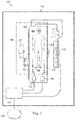
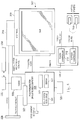
- FIG. 1 is a schematic drawing depicting a medical sensing system 100 including a bedside interface 102 according to one embodiment of the present disclosure.
- the medical sensing system 100 provides for coherent integration and consolidation of multiple forms of acquisition and processing elements designed to be sensitive to a variety of methods used to acquire and interpret human biological physiology and morphological information.
- the bedside interface 102 is a touch-enabled, integrated computing device for the acquisition, control, interpretation, measurement, and display of medical sensing data.
- the bedside interface 102 is a tablet-style touch-sensitive computer that provides user controls and diagnostic images on a single surface.
- the bedside interface 102 is operable to diagnostic visualizations and patient image data via graphical user interfaces (GUIs) corresponding to a plurality of medical sensing modalities.
- GUIs graphical user interfaces
- the bedside interface 102 will be described in greater detail in association with Figures 3-6 .
- the medical sensing system 100 is deployed in a catheter lab 104.
- the catheter lab 104 may be used to perform on a patient 106 any number of medical sensing procedures alone or in combination such as, by way of example and not limitation, angiography, intravascular ultrasound (IVUS), virtual histology (VH), forward looking IVUS (FL-IVUS), intravascular photoacoustic (IVPA) imaging, pressure, fractional flow reserve (FFR) determination, flow velocity, flow volume, coronary flow reserve (CFR) determination, optical coherence tomography (OCT), computed tomography, intracardiac echocardiography (ICE), forward-looking ICE (FLICE), intravascular palpography, transesophageal ultrasound, or any other medical sensing modalities known in the art.
- IVUS intravascular ultrasound
- VH virtual histology
- FL-IVUS forward looking IVUS
- IVPA intravascular photoacoustic
- FFR fractional flow reserve
- CFR coronary flow reserve
- OCT optical coherence tomography
- Catheter lab 104 can also conduct medical sensing procedures associated with Instant Wave-Free RatioTM Functionality (iFR® Functionality) (both trademarks of Volcano Corp.) and those disclosed in U.S. Patent Application No. 13/460,296 , entitled “DEVICES, SYSTEMS, AND METHODS FOR ASSESSING A VESSEL,” which discloses the use of pressure ratios that are available without application of a hyperemic agent. Further, medical sensing procedures associated with compensated Pd/Pa ratios suitable for estimating iFR®, FFR, and/or other accepted diagnostic pressure ratios as disclosed in U.S. Provisional Patent Application No.
- iFR® Functionality both trademarks of Volcano Corp.
- the catheter lab 104 further includes a sterile field 105 that encompasses the portions of the catheter lab surrounding the patient 106 on a procedure table 109 and a clinician 107, who may perform any number of medical sensing procedures or treatments.
- the bedside interface 102 may be positioned within the sterile field 105 and may be utilized by the clinician 107 to control a workflow of a medical sensing procedure or treatment being performed on the patient 106.
- the clinician 107 may initiate the procedure workflow, watch real-time medical sensing data, such as pressure measurements (e.g., visual representations of pressure data, such as pressure waveforms), obtained during the procedure, and interact with the obtained medical sensing data using the bedside interface 102 inside of the sterile field 105.
- the bedside interface may be used in conjunction with other imaging tools such as boom display 122.
- the bedside interface 102 and boom display 122 may display the same imagery, or the bedside interface 102 may provide alternative imagery to assist medical professionals in diagnosing a patient or performing surgery.
- the bedside interface 102 may show an alternative view angle or may overlay a highlighted image on that shown on the boom display 122.
- the bedside interface 102 may be used to provide additional details on specific areas of interest.
- the clinician 107 may view general diagnostic imagery on the boom display 122 and select a smaller portion of the imagery to display on the bedside interface 102.
- the magnification of the display on the bedside interface 102 may be variable, allowing the clinician to zoom in on particular areas while still keeping the general imagery in view on the boom display 122.
- the clinician 107 may zoom, rotate, and otherwise manipulate such images on the bedside interface 102 using simultaneous touch inputs (i.e. multitouch) and gestures.
- the bedside interface 102 may be utilized outside of the sterile field 105, for instance, in other locations within the catheter lab 104 or in a control room adjacent to the catheter lab 104.
- the medical sensing system 100 additionally includes a number of interconnected medical sensing-related tools in the catheter lab 104 to facilitate a pressure-sensing workflow procedure, such as a medical sensing device 108 and a medical sensing device 110, and a processing system 124.
- the medical sensing devices 108 and 110 can include pressure monitoring elements.
- Some embodiments of the medical sensing system 100 can include an patient interface module (PIM) 112 communicatively coupled to the medical sensing device 108, PIM 114 communicatively coupled to the medical sensing device 110, an electrocardiogram (ECG) device 116, an angiogram system 117, and a boom display 122.
- PIM patient interface module
- ECG electrocardiogram
- the bedside interface 102, PIMs 112 and 114, ECG device 116, angiography system 117, and boom display 122 are communicatively coupled to the processing system 124.
- the medical sensing devices 108 and 110 can include imaging elements to facilitate an imaging workflow.
- the processing system 124 is a computer workstation with the hardware and software to acquire, process, and display medical sensing data, but in other embodiments, the processing system may be any other type of computing system operable to process medical sensing data.
- the processing system 124 is operable to accept raw pressure data from the medical sensing devices 108 and 110 and/or the PIMs 112 and 114, transform the pressure data into screen displays including, e.g., visual representations such as pressure waveforms, numerical values, computed values, etc., and make the screen display available to the bedside interface 124, so that they may be displayed to the clinician 107 for analysis.
- screen displays including, e.g., visual representations such as pressure waveforms, numerical values, computed values, etc.
- the processing system 124 includes at least a processor such as a microinterface or a dedicated central processing unit (CPU), a non-transitory computer-readable storage medium such as a hard drive, random access memory (RAM), and/or compact disk read only memory (CD-ROM), a video interface such as a graphics processing unit (GPU), and a network communication device such as an Ethernet interface.
- a processor such as a microinterface or a dedicated central processing unit (CPU), a non-transitory computer-readable storage medium such as a hard drive, random access memory (RAM), and/or compact disk read only memory (CD-ROM), a video interface such as a graphics processing unit (GPU), and a network communication device such as an Ethernet interface.
- a processor such as a microinterface or a dedicated central processing unit (CPU), a non-transitory computer-readable storage medium such as a hard drive, random access memory (RAM), and/or compact disk read only memory (CD-ROM), a video interface such as a graphics processing unit
- the processing system 124 is communicatively coupled to a data network 125.
- the data network 125 is a TCP/IP-based local area network (LAN); however in other embodiments, it may utilize a different protocol such as Synchronous Optical Networking (SONET), or may be a wide area network (WAN).
- SONET Synchronous Optical Networking
- the network 125 may utilize wired and/or wireless connections. In some instances, at least a portion of the network 125 is a cellular network.
- Other components of the system 100 such as the bedside interface 102 and the boom display 122, are connected to the processing system 124 either directly through a wired or wireless interface, or indirectly via network 125 or other networking components.
- the processing system 124 may connect to various resources via the network 125, such as a Digital Imaging and Communications in Medicine (DICOM) system, a Picture Archiving and Communication System (PACS), and a Hospital Information System.
- the processing system 124 can be similar to a multi-modality processing system that processes medical sensing data disclosed in U.S. Patent No. 8,754,865 , entitled “MEDICAL MEASURING SYSTEM AND METHOD” and issued on June 17, 2014, and U.S. Patent Application No. 61/473,570 , entitled “MULTI-MODALITY MEDICAL SENSING SYSTEM AND METHOD” and filed on April 8, 2011.
- the PIM 112 and PIM 114 are operable to respectively receive medical sensing data collected from the patient 106 by the medical sensing device 108 and medical sensing device 110 and are operable to transmit the received data to the processing system 124.
- the PIM 112 and PIM 114 transmit the medical sensing data over a Peripheral Component Interconnect Express (PCIe) data bus connection, but, in other embodiments, they may transmit data over a USB connection, a Thunderbolt connection, a FireWire connection, or some other high-speed data bus connection.
- the ECG device 116 is operable to transmit electrocardiogram signals or other hemodynamic data from patient 106 to the processing system 124.
- the bedside interface 102 is operable to display the ECG data alongside medical sensing data.
- the processing system 124 may be operable to synchronize data collection with the catheters 108 and 110 using ECG signals from the ECG 116.
- the angiogram system 117 is operable to collect x-ray, computed tomography (CT), or magnetic resonance images (MRI) of the patient 106 and transmit them to the processing system 124.
- CT computed tomography
- MRI magnetic resonance images
- the processing system 124 may co-register image data from angiogram system 117 (e.g. x-ray data, MRI data, CT data, etc.) with sensing data from the catheters 108 and 110.
- the co-registration may be performed to generate three-dimensional images with the sensing data.
- Such co-registered 3-D images data maybe viewable on the bedside interface 124.
- a clinician may rotate, zoom, and otherwise manipulate such 3-D images on the bedside interface 102 using simultaneous touch inputs (i.e. multitouch) and gestures.
- medical sensing tools in system 100 are communicatively coupled to the processing system 124 via a wired connection such as a standard copper link or a fiber optic link.
- the bedside interface 124 may be communicatively and/or electrically coupled to the processing system 124 via a Universal Serial Bus (USB) connection, a Power-over-Ethernet connection, a Thunderbolt connection, a FireWire connection, or some other high-speed data bus connection.
- USB Universal Serial Bus
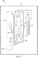
- Figure 2 is a schematic drawing depicting a medical sensing system 200 including a wireless bedside interface 202 according to another embodiment of the present disclosure.
- the medical sensing system 200 is similar to the system 100 of Figure 1 but the medical sensing tools including the wireless bedside interface 202, a wireless PIM 204, and a wireless PIM 206 communicate with a wireless network 208 via wireless networking protocols.
- the bedside interface 202 may send and receive workflow control parameters, medical sensing images, and measurement data to and from a remote processing system via IEEE 802.11 Wi-Fi standards, Ultra Wide-Band (UWB) standards, wireless FireWire, wireless USB, Bluetooth, or another high-speed wireless networking standard.
- IEEE 802.11 Wi-Fi standards Ultra Wide-Band (UWB) standards
- wireless FireWire wireless USB
- Bluetooth or another high-speed wireless networking standard.
- wireless capability allows the clinician 107 to more freely position the bedside interface 202 inside or outside of the sterile field 105 for better workflow management.
- the bedside interface 202 includes an integrally formed housing 302 that is easy to grasp and move around a catheter lab or other medical setting.
- the integrally formed housing 302 may be seamlessly molded from materials such as thermoplastic or thermosetting plastic or moldable metal.
- the integrally formed housing 302 may comprise a plurality of housing portions fixedly bonded in a substantially permanent manner to form an integral housing.
- the housing 302 is resistant to fluids, and, in one embodiment, may have a rating of IPX4 against fluid ingress as defined by the International Electrotechnical Commission (IEC) standard 60529.
- the hub may have a different fluid ingress rating.
- the housing 302 has a width, height, or thickness that is conducive to portability.
- the bedside interface 202 is configured to be used in conjunction with the boom display 122.
- the bedside interface 202 and boom display 122 receive data obtained by intravascular sensors and/or imaging components and display corresponding medical imagery 301.
- Such imagery 301 can include static images, video, 3-D renderings, raw sensor or imaging data, filtered sensor or imaging data, calculated sensor or imaging data, and/or other data representative of the patient's anatomy.
- This data may be collected during a diagnostic procedure or may be collected during a surgical procedure, such as PCI.
- diagnostic visualizations are overlaid on images of a vessel displayed on the boom display 122 and/or bedside interface 202. These diagnostic visualizations may assist the clinician 107 in determining the best available treatment options for a particular patient.
- the diagnostic visualizations can include markings, colors, numerical values, or other representations of the data obtained from medical instruments, such as guidewires and catheters.
- the diagnostic visualizations can include intensity maps based on recorded pressure measurements and may incorporate graphs of corresponding pressure ratios.
- the diagnostic visualizations may be overlaid onto extravascular images such as two-dimensional angiographic images, three-dimensional angiographic images, and computed tomography angiographic (CTA) images, and intravascular images such as ultrasound (IVUS) images and optical coherence tomography (OCT) images.
- the diagnostic visualizations can include one type of image overlaid onto another type of image.
- one or more treatment options can be simulated and the diagnostic visualizations updated based on the parameters associated with each particular simulated treatment option. In this manner, an estimated result or outcome for each treatment option can be visually provided to the clinician.
- the diagnostic visualizations and/or simulated treatments can be carried out as described in one or more of PCT Patent Application Publication No. WO 2013/028612, filed August 20, 2012 and titled “DEVICES, SYSTEMS, AND METHODS FOR VISUALLY DEPICTING A VESSEL AND EVALUATING TREATMENT OPTIONS," U.S. Provisional Patent Application No. 61/895,909, filed October 25, 2013 and titled “Devices, Systems, and Methods for Vessel Assessment," U.S. Provisional Patent Application No.
- a clinician can determine the best treatment option for the patient.
- Medical supervisors may also use the bedside interface 202 to check the work of clinicians 107 or to offer second opinions to a patient 106.
- Diagnostic visualizations may also be presented to a patient 106 or a caretaker of a patient 106 to assist a clinician 107 in explaining testing results or treatment options.
- the bedside interface 202 may be used to guide the placement of treatment devices during a procedure.
- a clinician 107 may use the bedside interface 202 to check the location of medical instruments, guidewires, or stents to ensure positional accuracy during the procedure.
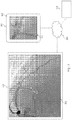
- a portion 303 of the imagery 301 is displayed on the bedside interface 202 to allow a clinician 107 to view specific areas of interest in the imagery 301.
- the bedside interface 202 is equipped with a touch screen interface, allowing a clinician 107 to easily manipulate imagery 301 using simultaneous touch inputs and gestures.
- the bedside interface 202 is configured to be able to zoom into areas of interest and display images, graphical information, and text relating to the imagery 301.
- Figure 3 shows that zoomed in portion 303 of the general imagery 301 that is displayed on the bedside interface 202.
- a communication network 208 connects the boom display 122 and the bedside interface 202 to the processing system 124.
- a wireless connection to the bedside interface 202 may be favored during diagnostic procedures to allow a clinician 107 to carry, reposition, or move the bedside display 202 as desired. This allows for continual monitoring of certain key aspects of the procedure, and may allow a clinician 107 to communicate diagnostic information and treatment options with a patient 106, another clinician 107, and/or a caretaker or family member of the patient.
- the bedside display 202 may also be used to display additional or more detailed diagnostic information for the portion 303 corresponding to the region of interest of the vessel.
- the boom display 122 displays imagery 301 of a patient while the bedside interface 202 shows the portion 303 of interest with diagnostic visualizations overlaid.
- pressure ratios such as FFR or iFR values, are shown along the region of interest of the vessel. As shown, there is a significant drop in the pressure ratio from 0.92 to 0.68 that can be indicative of a severe blockage or lesion. It is understood that any of a number of other types of diagnostic visualizations may be utilized as described above.
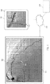
- one or more treatment options can be simulated and the diagnostic visualizations displayed on the bedside display 202 can be updated based on the parameters associated with a particular simulated treatment option.
- Figure 4 shows an example of this approach.
- Fig. 4 shows the simulated deployment of a stent 306 and the corresponding resulting change in the diagnostic visualizations.
- the severe drop to 0.68 shown Fig. 3 is estimated to be improved significantly by deployment of the stent to a value of 0.91.
- estimated results or outcomes for each treatment option can be visually provided to the clinician on the bedside display 202 and/or the overhead boom display 122.
- a simulated procedure may be displayed on the bedside interface 202 to show the likely outcome of a procedure.
- a simulated stent 306 is shown on the bedside interface 202 as well as statistical data 303 on the size and position of the stent.
- a clinician 107 may also place markers 305 on the imagery 301 of the bedside interface 202 to indicate important areas or provide ongoing pressure measurements. Simulations such as those shown in Figure 4 may afford a clinician 107 a view of both the predicted result of a procedure on the beside interface 202 and real-time imagery 301 of the patient on the boom display 122, affording a detailed and readily understandable analysis of treatment options. This analysis is also easily shared with a patient 106 or a patient's guardian or caretaker.
- FIG. 5 shows a functional block diagram of the bedside controller 300 according to aspects of the present disclosure.
- the touch-sensitive display 307 that comprises both a touch panel 308 and a flat panel display 309.
- the touch panel 308 overlays the flat panel display 308 and accepts user input via human touch, stylus touch, or some other analogous input method.
- the touch-sensitive display 307 displays images and accepts user input on the same surface.
- the touch panel 308 is a resistive-type panel, but in alternative embodiments it may be a capacitive-type panel, projective-type panel, or some other suitable type of touch enabled input panel.
- the touch panel 308 is operable to accept multiple inputs simultaneously (multitouch), for instance, to enable rotation of a three-dimensional rendering of a vessel along multiple axes. Additionally, the touch panel 308 is capable of receiving input when a sterile drape 301 is covering the bedside interface 300 and also when a user is gloved. The touch panel 308 is controlled by a touch interface 310 disposed within the housing 302. Further, when a clinician makes contact with the touch panel 308, the touch panel is operable to provide haptic feedback via a haptics interface 312 and haptics drivers 314. This haptic technology is operable to simulate a plurality of sensations on the touch panel 308 by varying the intensity and frequency of vibrations generated when a user contacts the touch panel.
- the housing 302 may include a sheath configured to store a stylus therein. Thus, a clinician may remove the stylus from the sheath in the housing to make measurements on the bedside interface and store it when the measurements have been completed.
- the flat panel display 309 Beneath the touch panel 308 is the flat panel display 309 that presents a graphical user interface (GUI) 316 to a user.
- GUI graphical user interface
- the flat panel display 309 is a LCD display but in alternative embodiments, it may be a different type of display such an LED display or an AMOLED display.
- the flat panel display 309 is illuminated by a LED backlight power inverter 318.
- the GUI 316 not only allows a clinician to control a medical sensing workflow, but also view and interact with pressure data obtained from a patient in the sterile field.
- the bedside interface 300 includes a single board processing platform 320 within the housing 302 that is operable to render the GUI 316 and process user touch input.
- the processing platform has a pico form factor and includes integrated processing components such as a processor 321, system memory 322, graphics processing unit (GPU), communications module 323, and I/O bus interface.
- the processor 321 may be a low power processor such as an Intel Atom® processor or an ARM-based processor
- the communications module 323 may be a 10/100/1Gb Ethernet module.
- the I/O bus interface may be a Universal Serial Bus (USB) interface.
- USB Universal Serial Bus
- the bedside interface 300 further includes a storage module 324 that is a non-transitory computer readable storage medium operable to store an operating system (i.e. software to render and control the GUI), data and/or visual representation manipulation software, medical sensing data and visual representations received from a processing system, and other medical sensing-related software.
- the processor 321 is configured to execute software and instructions stored on the storage module 324.
- the storage module 324 is a solid state drive (SSD) hard drive communicatively coupled to the processing platform 320 via a SATA connection, but, in alternative embodiments, it may be any other type of non-volatile or temporary storage module.
- the bedside interface 300 further includes a wireless communications module 326 communicatively coupled to the processing platform 320.
- the wireless communications module is an IEEE 802.11 Wi-Fi module, but in other may be an Ultra Wide-Band (UWB) wireless module, a wireless FireWire module, a wireless USB module, a Bluetooth module, or another high-speed wireless networking module.
- UWB Ultra Wide-Band
- the bedside interface 300 is powered via both a wired 12VDC power-over-Ethernet (PoE) connection 328 and a battery 330 disposed within the housing 302.
- the battery 330 may be sealed within the integrally formed housing 302 and may be recharged through electrical contacts disposed on the exterior of the housing and electrically coupled to the battery.
- the front wall 350 may include one or more electrical contacts 358 through which the battery 330 maybe charged when the interface is mounted to objects with compatible charging structure.
- the housing 302 may include a battery compartment with a removable cover to permit battery replacement. Such a battery compartment cover may be resistant to fluid ingress (e.g., with an IPX4 rating).
- the beside interface 300 may be coupled to a processing system in the catheter lab via the PoE connection 328, over which it receives medical sensing images that have been captured from the patient and rendered on the processing system.
- a processing system in the catheter lab via the PoE connection 328, over which it receives medical sensing images that have been captured from the patient and rendered on the processing system.
- the bedside interface when the bedside interface is coupled to the PoE connection 328, it receives power and communications over the same physical wire.
- the bedside interface 300 is disconnected from the PoE connection 328, it runs on battery power and receives data wirelessly via the wireless communications module 326.
- the beside interface may directly communicate with a processing system (i.e. in an ad-hoc wireless mode), or, alternatively, it may communicate with a wireless network that serves a plurality of wireless devices.
- the bedside interface 300 may receive power and data through different wired connections, or receive data communications through a wired data connection and power from the battery 330, or receive data communications through the wireless module 326 and power from a wired electrical connection.
- the bedside interface 300 may be used in a semi-wireless configuration, in which the battery 330 provides backup power to the interface when the interface is temporarily disconnected from a wired power source. For example, if at the beginning of a procedure, the bedside interface 300 is connected to a PoE connection (or other type of wired connection) and during the procedure the interface must be disconnected from the PoE connection to allow for a cabling adjustment, the battery 330 may keep the interface alive until a PoE connection can be reestablished. In this manner, a full power-off and reboot of the interface 300 is avoided during a procedure.
- a DC-DC power converter 332 converts input voltage to a voltage usable by the processing platform 320.
- the bedside interface 300 includes specific components described herein, the bedside interface may include any number of additional components, for example a charge regulator interposed between the electrical contacts and the battery, and may be configured in any number of alternative arrangements in alternative embodiments.
- Figure 6 is a flowchart illustrating an exemplary method 600 of planning the treatment of a patient.
- the method 600 will be described in the context of a pressure-sensing procedure, such as an iFR procedure, but may equally apply to any number of medical sensing or treatment procedures, such as an FFR procedure, an IVUS procedure, OCT procedure, a FLIVUS procedure, an ICE procedure, etc.
- the method 600 can be better understood with reference to the Figures 7-10 .
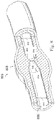
- FIG. 800 shown therein is a vessel 800 having a stenosis according to an exemplary illustration.
- Figure 7 is a diagrammatic perspective view of the vessel 800
- Figure 8 is a partial cross-sectional perspective view of a portion of the vessel 800.
- the vessel 800 includes a proximal portion 802 and a distal portion 804.
- a lumen 806 extends along the length of the vessel 800 between the proximal portion 802 and the distal portion 804.
- the lumen 806 is configured to allow the flow of fluid through the vessel.
- the vessel 800 is a blood vessel.
- the vessel 800 is a coronary artery.
- the lumen 806 is configured to facilitate the flow of blood through the vessel 800.
- the vessel 800 includes a stenosis 808 between the proximal portion 802 and the distal portion 804.
- Stenosis 808 is generally representative of any blockage or other structural arrangement that results in a restriction to the flow of fluid through the lumen 806 of the vessel 800.
- Embodiments of the present disclosure are suitable for use in a wide variety of vascular applications, including without limitation coronary, peripheral (including but not limited to lower limb, carotid, and neurovascular), renal, and/or venous.
- the stenosis 808 may be a result of plaque buildup, including without limitation plaque components such as fibrous, fibro-lipidic (fibro fatty), necrotic core, calcified (dense calcium), blood, fresh thrombus, and mature thrombus.
- plaque components such as fibrous, fibro-lipidic (fibro fatty), necrotic core, calcified (dense calcium), blood, fresh thrombus, and mature thrombus.
- the composition of the stenosis will depend on the type of vessel being evaluated. In that regard, it is understood that the concepts of the present disclosure are applicable to virtually any type of blockage or other narrowing of a vessel that results in decreased fluid flow.
- the lumen 806 of the vessel 800 has a diameter 810 proximal of the stenosis 808 and a diameter 812 distal of the stenosis.
- the diameters 810 and 812 are substantially equal to one another.
- the diameters 810 and 812 are intended to represent healthy portions, or at least healthier portions, of the lumen 806 in comparison to stenosis 808. Accordingly, these healthier portions of the lumen 806 are illustrated as having a substantially constant cylindrical profile and, as a result, the height or width of the lumen has been referred to as a diameter.
- the diameters 810 and 812 are understood to be representative of a relative size or cross-sectional area of the lumen and do not imply a circular cross-sectional profile.
- stenosis 808 includes plaque buildup 814 that narrows the lumen 806 of the vessel 800.
- the plaque buildup 814 does not have a uniform or symmetrical profile, making angiographic evaluation of such a stenosis unreliable.
- the plaque buildup 814 includes an upper portion 816 and an opposing lower portion 818.
- the lower portion 818 has an increased thickness relative to the upper portion 816 that results in a non-symmetrical and non-uniform profile relative to the portions of the lumen proximal and distal of the stenosis 808.
- the plaque buildup 814 decreases the available space for fluid to flow through the lumen 806.
- the cross-sectional area of the lumen 806 is decreased by the plaque buildup 814.
- the lumen 806 has a height 820, which is representative of a reduced size or cross-sectional area relative to the diameters 810 and 812 proximal and distal of the stenosis 808.
- the stenosis 808, including plaque buildup 814 is exemplary in nature and should be considered limiting in any way. In that regard, it is understood that the stenosis 808 has other shapes and/or compositions that limit the flow of fluid through the lumen 806 in other instances.
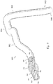
- instruments 830 and 832 may be any form of device, instrument, or probe sized and shaped to be positioned within a vessel.
- the instruments 830 and 832 can be implemented in the medical sensing system 100 ( Figure 1 ) as medical sensing devices 108 and 110.
- instrument 830 is generally representative of a guide wire
- instrument 832 is generally representative of a catheter.
- instrument 830 extends through a central lumen of instrument 832.
- the instruments 830 and 832 take other forms.
- the instruments 830 and 832 are of similar form in some embodiments.
- both instruments 830 and 832 are guide wires. In other instances, both instruments 830 and 832 are catheters.
- the instruments 830 and 832 are of different form in some embodiments, such as the illustrated embodiment, where one of the instruments is a catheter and the other is a guide wire.
- the instruments 830 and 832 are disposed coaxial with one another, as shown in the illustrated embodiment of Figure 9 . In other instances, one of the instruments extends through an off-center lumen of the other instrument. In yet other instances, the instruments 830 and 832 extend side-by-side. In some particular embodiments, at least one of the instruments is as a rapid-exchange device, such as a rapid-exchange catheter.
- the other instrument is a buddy wire or other device configured to facilitate the introduction and removal of the rapid-exchange device.
- the single instrument incorporates aspects of the functionalities (e.g., data acquisition) of both instruments 830 and 832.
- Instrument 830 is configured to obtain diagnostic information about the vessel 800.
- the instrument 830 includes one or more sensors, transducers, and/or other monitoring elements configured to obtain the diagnostic information about the vessel.
- the diagnostic information includes one or more of pressure, flow (velocity and/or volume), images (including images obtained using ultrasound (e.g., IVUS), OCT, thermal, and/or other imaging techniques), temperature, and/or combinations thereof.
- the one or more sensors, transducers, and/or other monitoring elements are positioned adjacent a distal portion of the instrument 830 in some instances.
- the one or more sensors, transducers, and/or other monitoring elements are positioned less than 30 cm, less than 10 cm, less than 5 cm, less than 3 cm, less than 2 cm, and/or less than 1 cm from a distal tip 834 of the instrument 830 in some instances. In some instances, at least one of the one or more sensors, transducers, and/or other monitoring elements is positioned at the distal tip of the instrument 830.
- the instrument 830 includes at least one element configured to monitor pressure within the vessel 800.
- the pressure monitoring element can take the form a piezo-resistive pressure sensor, a piezo-electric pressure sensor, a capacitive pressure sensor, an electromagnetic pressure sensor, a fluid column (the fluid column being in communication with a fluid column sensor that is separate from the instrument and/or positioned at a portion of the instrument proximal of the fluid column), an optical pressure sensor, and/or combinations thereof.
- one or more features of the pressure monitoring element are implemented as a solid-state component manufactured using semiconductor and/or other suitable manufacturing techniques.
- the instrument 830 is sized such that it can be positioned through the stenosis 808 without significantly impacting fluid flow across the stenosis, which would impact the distal pressure reading. Accordingly, in some instances the instrument 830 has an outer diameter of 0.4572 mm or less. In some embodiments, the instrument 830 has an outer diameter of 0.3556 mm or less.
- Instrument 832 is also configured to obtain diagnostic information about the vessel 100. In some instances, instrument 832 is configured to obtain the same diagnostic information as instrument 830. In other instances, instrument 832 is configured to obtain different diagnostic information than instrument 830, which may include additional diagnostic information, less diagnostic information, and/or alternative diagnostic information.
- the diagnostic information obtained by instrument 832 includes one or more of pressure, flow (velocity and/or volume), images (including images obtained using ultrasound (e.g., IVUS), OCT, thermal, and/or other imaging techniques), temperature, and/or combinations thereof. Instrument 832 includes one or more sensors, transducers, and/or other monitoring elements configured to obtain this diagnostic information.
- the one or more sensors, transducers, and/or other monitoring elements are positioned adjacent a distal portion of the instrument 832 in some instances. In that regard, the one or more sensors, transducers, and/or other monitoring elements are positioned less than 30 cm, less than 10 cm, less than 5 cm, less than 3 cm, less than 2 cm, and/or less than 1 cm from a distal tip 836 of the instrument 832 in some instances. In some instances, at least one of the one or more sensors, transducers, and/or other monitoring elements is positioned at the distal tip of the instrument 832.
- instrument 832 also includes at least one element configured to monitor pressure within the vessel 800.
- the pressure monitoring element can take the form a piezo-resistive pressure sensor, a piezo-electric pressure sensor, a capacitive pressure sensor, an electromagnetic pressure sensor, a fluid column (the fluid column being in communication with a fluid column sensor that is separate from the instrument and/or positioned at a portion of the instrument proximal of the fluid column), an optical pressure sensor, and/or combinations thereof.
- one or more features of the pressure monitoring element are implemented as a solid-state component manufactured using semiconductor and/or other suitable manufacturing techniques.
- Siemens AXIOM Sensis, Mennen Horizon XVu, and Philips Xper IM Physiomonitoring 5 can be utilized for instrument 832 in some instances.
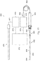
- At least one of the instruments 830 and 832 is configured to monitor a pressure within the vessel 800 distal of the stenosis 808 and at least one of the instruments 830 and 832 is configured to monitor a pressure within the vessel proximal of the stenosis.
- the instruments 830, 832 are sized and shaped to allow positioning of the at least one element configured to monitor pressure within the vessel 800 to be positioned proximal and/or distal of the stenosis 808 as necessary based on the configuration of the devices.
- Figure 9 illustrates a position 838 suitable for measuring pressure distal of the stenosis 808.
- the position 838 is less than 5 cm, less than 3 cm, less than 2 cm, less than 1 cm, less than 5 mm, and/or less than 2.5 mm from the distal end of the stenosis 808 (as shown in Figure 8 ) in some instances.
- Figure 9 also illustrates a plurality of suitable positions for measuring pressure proximal of the stenosis 808.
- positions 840, 842, 844, 846, and 848 each represent a position that is suitable for monitoring the pressure proximal of the stenosis in some instances.
- the positions 840, 842, 844, 846, and 848 are positioned at varying distances from the proximal end of the stenosis 808 ranging from more than 20 cm down to about 5 mm or less.
- the proximal pressure measurement will be spaced from the proximal end of the stenosis. Accordingly, in some instances, the proximal pressure measurement is taken at a distance equal to or greater than an inner diameter of the lumen of the vessel from the proximal end of the stenosis.
- the proximal pressure measurement is generally taken at a position proximal of the stenosis and distal of the aorta, within a proximal portion of the vessel.
- the proximal pressure measurement is taken from a location inside the aorta. In other instances, the proximal pressure measurement is taken at the root or ostium of the coronary artery.
- At least one of the instruments 830 and 832 is configured to monitor pressure within the vessel 800 while being moved through the lumen 806.
- instrument 830 is configured to be moved through the lumen 806 and across the stenosis 808.
- the instrument 830 is positioned distal of the stenosis 808 and moved proximally (i.e., pulled back) across the stenosis to a position proximal of the stenosis in some instances.
- the instrument 830 is positioned proximal of the stenosis 808 and moved distally across the stenosis to a position distal of the stenosis.
- Movement of the instrument 830, either proximally or distally is controlled manually by medical personnel (e.g., hand of a surgeon) in some embodiments.
- movement of the instrument 830, either proximally or distally is controlled automatically by a movement control device (e.g., a pullback device, such as the Trak Back® II Device available from Volcano Corporation).
- the movement control device controls the movement of the instrument 830 at a selectable and known speed (e.g., 2.0 mm/s, 1.0 mm/s, 0.5 mm/s, 0.2 mm/s, etc.) in some instances. Movement of the instrument 830 through the vessel is continuous for each pullback or push through, in some instances.
- the instrument 830 is moved step-wise through the vessel (i.e., repeatedly moved a fixed amount of distance and/or a fixed amount of time).
- Some aspects of the visual depictions discussed below are particularly suited for embodiments where at least one of the instruments 830 and 832 is moved through the lumen 806. Further, in some particular instances, aspects of the visual depictions discussed below are particularly suited for embodiments where a single instrument is moved through the lumen 806, with or without the presence of a second instrument.
- a single instrument has a benefit in that it avoids issues associated with variations in pressure measurements of one instrument relative to another over time, which is commonly referred to as drift.
- drift a major source of drift in traditional Fractional Flow Reserve (FFR) measurements is divergence in the pressure reading of a guide wire relative to the pressure reading of a guide catheter.
- FFR Fractional Flow Reserve
- this divergence has an impact on the resulting FFR value.
- drift is negligible or non-existent.
- the single instrument is utilized to obtain relative changes in pressures as it is moved through the vessel such that the time period between pressure measurements is short enough to prevent any impact from any changes in pressure sensitivity of the instrument (e.g., less than 500 ms, less than 100 ms, less than 50 ms, less than 10 ms, less than 5 ms, less than 1 ms, or otherwise).
- the time period between pressure measurements is short enough to prevent any impact from any changes in pressure sensitivity of the instrument (e.g., less than 500 ms, less than 100 ms, less than 50 ms, less than 10 ms, less than 5 ms, less than 1 ms, or otherwise).
- Figure 10 is a diagrammatic, schematic view of the system 850.
- the system 850 can be implemented as the medical sensing system 100 ( Figure 1 ).
- one or more components of the medical sensing system 100 can be additionally implemented in the system 850, such as a bedside interface having a touch-sensitive display.
- the system 850 includes an instrument 852.
- instrument 852 is suitable for use as at least one of instruments 830 and 832 ( Figs. 8-10 ) and/or medical sensing devices 108 and 110 ( Figure 1 ), discussed above.
- the instrument 852 includes features similar to those discussed above with respect to instruments 830 and 832 in some instances.
- the instrument 852 is a guide wire having a distal portion 854 and a housing 856 positioned adjacent the distal portion.
- the housing 856 is spaced approximately 3 cm from a distal tip of the instrument 852.
- the housing 856 is configured to house one or more sensors, transducers, and/or other monitoring elements configured to obtain the diagnostic information about the vessel.
- the housing 856 contains at least a pressure sensor configured to monitor a pressure within a lumen in which the instrument 852 is positioned.
- a shaft 858 extends proximally from the housing 856.
- a torque device 860 is positioned over and coupled to a proximal portion of the shaft 858.
- a proximal end portion 862 of the instrument 852 is coupled to a connector 864.
- a cable 866 extends from connector 864 to a connector 868.
- connector 868 is configured to be plugged into an interface 870.
- interface 870 is a patient interface module (PIM) in some instances.
- PIM patient interface module
- the interface 870 can be implemented as the PIM 112 ( Figure 1 ).
- the cable 866 is replaced with a wireless connection.
- various communication pathways between the instrument 852 and the interface 870 may be utilized, including physical connections (including electrical, optical, and/or fluid connections), wireless connections, and/or combinations thereof.
- the interface 870 is communicatively coupled to a computing device 872 via a connection 874.
- Computing device 872 is generally representative of any device suitable for performing the processing and analysis techniques discussed within the present disclosure.
- the computing device 872 includes a processor, random access memory, and a storage medium.
- the computing device 872 is programmed to execute steps associated with the data acquisition and analysis described herein. Accordingly, it is understood that any steps related to data acquisition, data processing, instrument control, and/or other processing or control aspects of the present disclosure may be implemented by the computing device using corresponding instructions stored on or in a non-transitory computer readable medium accessible by the computing device.
- the computing device 872 is the bedside interface.
- the processing steps described herein can be performed by one or more processing components of the bedside interface, such as the processing platform 320.
- the computing device 872 is a console device.
- the computing device 872 is similar to the s5TM Imaging System or the s5iTM Imaging System, each available from Volcano Corporation.
- the computing device 872 is portable (e.g., handheld, on a rolling cart, etc.).
- the computing device 872 comprises a plurality of computing devices.
- the different processing and/or control aspects of the present disclosure may be implemented separately or within predefined groupings using a plurality of computing devices. Any divisions and/or combinations of the processing and/or control aspects described below across multiple computing devices are within the scope of the present disclosure.
- connection 874 facilitate communication between the one or more sensors, transducers, and/or other monitoring elements of the instrument 852 and the computing device 872.
- this communication pathway is exemplary in nature and should not be considered limiting in any way.
- any communication pathway between the instrument 852 and the computing device 872 may be utilized, including physical connections (including electrical, optical, and/or fluid connections), wireless connections, and/or combinations thereof.
- the connection 874 is wireless in some instances.
- the connection 874 includes a communication link over a network (e.g., intranet, internet, telecommunications network, and/or other network).
- the computing device 872 is positioned remote from an operating area where the instrument 152 is being used in some instances. Having the connection 874 include a connection over a network can facilitate communication between the instrument 852 and the remote computing device 872 regardless of whether the computing device is in an adjacent room, an adjacent building, or in a different state/country. Further, it is understood that the communication pathway between the instrument 852 and the computing device 872 is a secure connection in some instances. Further still, it is understood that, in some instances, the data communicated over one or more portions of the communication pathway between the instrument 852 and the computing device 872 is encrypted.
- the system 850 also includes an instrument 875.
- instrument 875 is suitable for use as at least one of instruments 830 and 832 ( Figures 7-9 ) and/or medical sensing devices 108 and 110 ( Figure 1 ), discussed above.
- the instrument 875 includes features similar to those discussed above with respect to instruments 130 and 132 in some instances.
- the instrument 875 is a catheter-type device.
- the instrument 875 includes one or more sensors, transducers, and/or other monitoring elements adjacent a distal portion of the instrument configured to obtain the diagnostic information about the vessel.
- the instrument 875 includes a pressure sensor configured to monitor a pressure within a lumen in which the instrument 875 is positioned.
- instrument 875 is in communication with an interface 876 via connection 877.
- interface 876 is a hemodynamic monitoring system or other control device, such as Siemens AXIOM Sensis, Mennen Horizon XVu, and Philips Xper IM Physiomonitoring 5.
- instrument 875 is a pressure-sensing catheter that includes fluid column extending along its length.
- interface 876 includes a hemostasis valve fluidly coupled to the fluid column of the catheter, a manifold fluidly coupled to the hemostasis valve, and tubing extending between the components as necessary to fluidly couple the components.
- the fluid column of the catheter is in fluid communication with a pressure sensor via the valve, manifold, and tubing.
- the pressure sensor is part of interface 876.
- the pressure sensor is a separate component positioned between the instrument 875 and the interface 876.
- the interface 876 is communicatively coupled to the computing device 872 via a connection 878.
- interface 876 and connections 877 and 878 facilitate communication between the one or more sensors, transducers, and/or other monitoring elements of the instrument 875 and the computing device 872.
- this communication pathway is exemplary in nature and should not be considered limiting in any way.
- any communication pathway between the instrument 875 and the computing device 872 may be utilized, including physical connections (including electrical, optical, and/or fluid connections), wireless connections, and/or combinations thereof.
- the connection 878 is wireless in some instances.
- the connection 878 includes a communication link over a network (e.g., intranet, internet, telecommunications network, and/or other network).
- the computing device 872 is positioned remote from an operating area where the instrument 875 is being used in some instances. Having the connection 878 include a connection over a network can facilitate communication between the instrument 875 and the remote computing device 872 regardless of whether the computing device is in an adjacent room, an adjacent building, or in a different state/country. Further, it is understood that the communication pathway between the instrument 875 and the computing device 872 is a secure connection in some instances. Further still, it is understood that, in some instances, the data communicated over one or more portions of the communication pathway between the instrument 875 and the computing device 872 is encrypted.
- the system 850 does not include interface 870 and/or interface 876.
- the connector 868 (or other similar connector in communication with instrument 852 or instrument 875) may plug into a port associated with computing device 872.
- the instruments 852, 875 may communicate wirelessly with the computing device 872.
- the communication pathway between either or both of the instruments 852, 875 and the computing device 872 may have no intermediate nodes (i.e., a direct connection), one intermediate node between the instrument and the computing device, or a plurality of intermediate nodes between the instrument and the computing device.
- the system 850 can additionally include a bedside interface, such as the bedside interface of medical sensing system 100 ( Figure 1 ).
- the bedside interface maybe utilized by a clinician to control a instruments 852 and 875 to acquire pressure data during a procedure, watch real-time medical pressure measurements (e.g., visual representations of pressure data, such as pressure waveforms, numerical values, etc.), and interact with the obtained medical sensing data using the bedside interface.
- the bedside interface can be communicatively coupled to the computing device 872, the interfaces 870 and 876, and/or the instruments 864 and 875.
- the exemplary method 600 begins at block 610 where pressure measurements are obtained using diagnostic instruments such as instruments 830, 832.
- the diagnostic instruments are also configured to obtain diagnostic information about the vessel 800.
- these instruments 830, 320 are sized and shaped to allow positioning of the at least one element configured to monitor pressure within the vessel 800 to be positioned proximal and/or distal of stenosis 808 as necessary based on the configuration of the devices.
- sensors may be integrated with this instrument, such as piezo-resistive pressure sensors, piezo-electric pressure sensors, capacitive pressure sensors, electromagnetic pressure sensors, a fluid column, optical pressure sensors, and/or combinations thereof.
- the pressure measurement data is transmitted to a processing system.
- This processing system may take the form a computing device 872.
- the pressure measurement data may be sent directly to a PIM 112 or interface 870.
- the transmission of data may be accomplished through a wired connection (using cable 866) or a wireless connection.
- the processing system may be positioned remote from an operating area where the diagnostic instrument is being used. Having the connection 874 include a connection over a network can facilitate communication between the diagnostic instrument and the processing system regardless of whether the computing device is in an adjacent room, an adjacent building, or in a different state/country.
- a processing system may collect raw pressure data from the diagnostic instrument and process the data to render visual representations of the obtained pressure data.
- data is transmitted to the boom display 122 and bedside interface 202 to facilitate the display of medical imagery.
- This medical imagery may be diagnostic visualizations and may include numerical, graphical, textual, and/or other suitable visualizations.
- the bedside interface 202 and boom display 122 retrieve the visual representations from the processing system and displays them to a user in real-time.
- a PIM 112 or interface 870 may be used in conjunction with a bedside interface 202 to display diagnostic representations to a clinician 107 or patient 106.
- the bedside interface 202 is used to display a close up region of interest.
- the bedside interface may present pressure measurements or visual representations of the obtained pressure data on the bedside interface and the clinician 107 may navigate through them using gestures on the bedside interface's 202 touch panel.
- This close up region may show details not apparent in the more general display on the boom display 122, and specified statistical data may accompany this close up display.
- a clinician 107 analyzes the medical imagery or diagnostic visualization on the bedside interface 202.
- the clinician analyzes the obtained pressure data or visual representations of the obtained pressure data, directly on the bedside interface 202.
- the user of the bedside interface interacts with the obtained pressure data or visual representations through a series of presses, moves and releases using a finger or stylus on the interface's touch-sensitive display. These actions are interpreted by the bedside interface's 202 internal processor.
- the obtained pressure data and/or visual representations can be modified in response to the user touch inputs. For example, a user touch input on the bedside interface 202 can select a specific point of a pressure waveform that corresponds to a specific time at which pressure measurements were obtained.
- a user may be able to check pressure measurements associated with different sections of the vessel.
- pressure data obtained at the specific time can be displayed proximate the specific point on the pressure waveform on the bedside interface.
- the clinician 107 may share the visualizations with a patient 106 at this step.
- a clinician 700 plans a percutaneous coronary intervention based on the analysis with the bedside interface.
- the bedside interface may be used to place virtual markers on diagnostic visualizations, or to list pressure data to be used on the planning process. Additionally, diagnostic visualizations may be overlaid on images of a vessel displayed on the boom display 122 and/or bedside interface 202. These diagnostic visualizations may assist the clinician 107 in determining the best available treatment options for a particular patient.
Description
- The present disclosure relates generally to the assessment of vessels using a bedside interface. For example, some embodiments of the present disclosure are suited for assessing the severity of a blockage or other restriction to the flow of fluid through a vessel, such as a stenosis of a human blood vessel, by analyzing medical sensing data collected from the vessel using a touch-sensitive display of the bedside interface for use in percutaneous coronary intervention (PCI) planning.
- Innovations in diagnosing and verifying the level of success of treatment of disease have progressed from solely external imaging processes to include internal diagnostic processes. In addition to traditional external image techniques such as X-ray, MRI, CT scans, fluoroscopy, and angiography, small sensors may now be placed directly in the body. For example, diagnostic equipment and processes have been developed for diagnosing vasculature blockages and other vasculature disease by means of ultra-miniature sensors placed upon the distal end of a flexible elongate member such as a catheter, or a guide wire used for catheterization procedures. For example, known medical sensing techniques include intravascular ultrasound (IVUS), forward looking IVUS (FL-IVUS), fractional flow reserve (FFR) determination, a coronary flow reserve (CFR) determination, optical coherence tomography (OCT), trans-esophageal echocardiography, and image-guided therapy. Traditionally, many of these procedures are carried out by a multitude of physicians and clinicians, where each performs an assigned task. For example, a physician may stand next to a patient in the sterile field and guide the insertion and pull back of a medical sensing catheter. A clinician near the physician may control the procedure workflow with an interface, for example by starting and stopping the acquisition of medical data. Further, once medical data has been acquired, a second clinician in an adjacent control room working at a desktop computer may analyze the data, such as by reviewing quantities calculated from the acquired data. If a display is available in the sterile field, it is static and a physician may need to look at several images in succession. Also, the physician in the catheter lab and the clinician in the control room must communicate in order to acquire and analyze the relevant medical data. This may lengthen the time of the procedure, increase the cost of the procedure, and may lead to errors due to miscommunication or clinician inexperience.
US20140188503 discloses a system with dual display devices, with a boom display and a bedside touch screen controller. - A currently accepted technique for assessing the severity of a stenosis in the blood vessel, including ischemia causing lesions, is fractional flow reserve (FFR). FFR is a calculation of the ratio of a distal pressure measurement (taken on the distal side of the stenosis) relative to a proximal pressure measurement (taken on the proximal side of the stenosis). FFR provides an index of stenosis severity that allows determination as to whether the blockage limits blood flow within the vessel to an extent that treatment is required. The normal value of FFR in a healthy vessel is 1.00, while values less than about 0.80 are generally deemed significant and require treatment. Common treatment options include angioplasty and stenting. Coronary blood flow is unique in that it is affected not only by fluctuations in the pressure arising proximally (as in the aorta) but is also simultaneously affected by fluctuations arising distally in the microcirculation. Accordingly, it is not possible to accurately assess the severity of a coronary stenosis by simply measuring the fall in mean or peak pressure across the stenosis because the distal coronary pressure is not purely a residual of the pressure transmitted from the aortic end of the vessel. As a result, for an effective calculation of FFR within the coronary arteries, it is necessary to reduce the vascular resistance within the vessel. Currently, pharmacological hyperemic agents, such as adenosine, are administered to reduce and stabilize the resistance within the coronary arteries. These potent vasodilator agents reduce the dramatic fluctuation in resistance predominantly by reducing the microcirculation resistance associated with the systolic portion of the heart cycle to obtain a relatively stable and minimal resistance value.
- However, the administration of hyperemic agents is not always possible or advisable. First, the clinical effort of administering hyperemic agents can be significant. In some countries (particularly the United States), hyperemic agents such as adenosine are expensive, and time consuming to obtain when delivered intravenously (IV). In that regard, IV-delivered adenosine is generally mixed on a case-by-case basis in the hospital pharmacy. It can take a significant amount of time and effort to get the adenosine prepared and delivered to the operating area. These logistic hurdles can impact a physician's decision to use FFR. Second, some patients have contraindications to the use of hyperemic agents such as asthma, severe COPD, hypotension, bradycardia, low cardiac ejection fraction, recent myocardial infarction, and/or other factors that prevent the administration of hyperemic agents. Third, many patients find the administration of hyperemic agents to be uncomfortable, which is only compounded by the fact that the hyperemic agent may need to be applied multiple times during the course of a procedure to obtain FFR measurements. Fourth, the administration of a hyperemic agent may also require central venous access (e.g., a central venous sheath) that might otherwise be avoided. Finally, not all patients respond as expected to hyperemic agents and, in some instances, it is difficult to identify these patients before administration of the hyperemic agent.
- Accordingly, there remains a need for improved devices, systems, and methods for assessing the severity of a blockage in a vessel and, in particular, a stenosis in a blood vessel. There also remains a need for improved devices, systems, and methods for providing visual depictions of vessel that allow assessment of the vessel and, in particular, any stenosis or lesion of the vessel. Further, there remains a need for assessing the severity of a stenosis and for providing visual depictions of the vessel in an efficient and user friendly manner to facilitate PCI planning.
- Embodiments of the present disclosure are configured to assess the severity of a blockage in a vessel and, in particular, a stenosis in a blood vessel, provide visual depictions of vessel that allow assessment of the vessel and, in particular, any stenosis or lesion of the vessel, and simulate one or more treatment options for the vessel to facilitate planning and execution of percutaneous coronary interventions.
- As background information methods of planning the treatment of a vessel of a patient are described. These comprise obtaining pressure measurements from first and second instruments positioned within a vessel of a patient during a diagnostic procedure where the second instrument is moved longitudinally through the vessel from a first position to a second position and the first instrument remains stationary within the vessel; displaying on a first visualization device an image of the vessel with treatment diagnostic visualizations based on the obtained pressure measurements; and displaying on a second visualization device a portion of the image of the vessel with diagnostic visualizations based on the obtained pressure measurements, wherein the portion of the image of the vessel displayed on the second visualization device is a close up of a region of interest of the vessel.
- The first and second visualization devices are utilized to guide placement of one or more treatment devices associated with the identified treatment option. The second visualization device may also comprise a touch screen. The image displayed on the second visualization device may be at a higher magnification than the image displayed on the first visualization device. The second visualization device may be capable of higher magnification than the first visualization device.
- In some instances, the image of the vessel comprises an extravascular image, and may be at least one of a two dimensional angiographic image, a three dimensional angiographic image, and a computed tomography angiographic (CTA) image. Alternatively, the image of the vessel comprises an intravascular image and may be at least one of an intravascular ultrasound (IVUS) image and an optical coherence tomography (OCT) image.
- The diagnostic visualizations may include at least one of pressure measurements from the first instrument, pressure measurements from the second instrument, a ratio of the pressure measurements from the first and second instruments, an FFR value, or an iFR value. Additionally, the diagnostic visualizations may include an intensity map based on changes in a pressure ratio of the obtained pressure measurements from the first and second instruments, or a graph of a gradient of a pressure ratio of the obtained pressure measurements from the first and second instruments.
- A first treatment option is simulated, wherein simulating the first treatment option includes modifying the diagnostic visualizations based on an expected result of the first treatment option. Additionally, a second treatment option may be simulated, wherein simulating the second treatment option includes modifying the diagnostic visualizations based on an expected result of the second treatment option; and comparing the modified diagnostic visualizations associated with the first and second treatment options to identify a recommended treatment option. The first and second treatment options may be selected from the group consisting of performing angioplasty, deploying one or more stents, applying a pharmaceutical agent, or combinations thereof.
- A system for planning the treatment of a vessel of a patient is provided, comprising: a first instrument sized and shaped for introduction into the vessel of the patient, and a second instrument sized and shaped for introduction into the vessel of the patient; a processing system in communication with the first and second instruments, the processing system configured to: obtain pressure measurements from first and second instruments positioned within the vessel of the patient during a diagnostic procedure; display on a first visualization device an image of the vessel with treatment diagnostic visualizations based on the obtained pressure measurements; and display on a second visualization device a portion of the image of the vessel with diagnostic visualizations based on the obtained pressure measurements, wherein the portion of the image of the vessel displayed on the second visualization device is a close up of a region of interest of the vessel; and simulate a first treatment option, wherein simulating the first treatment option includes modifying the diagnostic visualizations based on an expected result of the first treatment option.
- In some embodiments, the first and second visualization devices are utilized to guide placement of one or more treatment devices associated with the identified treatment option. The second visualization device may also comprise a touch screen. The image displayed on the second visualization device may be at a higher magnification than the image displayed on the first visualization device. The second visualization device may be capable of higher magnification than the first visualization device.
- In some instances, the image of the vessel comprises an extravascular image, and may be at least one of a two dimensional angiographic image, a three dimensional angiographic image, and a computed tomography angiographic (CTA) image. Alternatively, the image of the vessel comprises an intravascular image and may be at least one of an intravascular ultrasound (IVUS) image and an optical coherence tomography (OCT) image.
- The diagnostic visualizations may include at least one of pressure measurements from the first instrument, pressure measurements from the second instrument, a ratio of the pressure measurements from the first and second instruments, an FFR value, or an iFR value. Additionally, the diagnostic visualizations may include an intensity map based on changes in a pressure ratio of the obtained pressure measurements from the first and second instruments, or a graph of a gradient of a pressure ratio of the obtained pressure measurements from the first and second instruments.
- Additionally, a second treatment option may be simulated, wherein simulating the second treatment option includes modifying the diagnostic visualizations based on an expected result of the second treatment option; and comparing the modified diagnostic visualizations associated with the first and second treatment options to identify a recommended treatment option. The first and second treatment options may be selected from the group consisting of performing angioplasty, deploying one or more stents, applying a pharmaceutical agent, or combinations thereof.
- Additional aspects, features, and advantages of the present disclosure will become apparent from the following detailed description.
- Illustrative embodiments of the present disclosure will be described with reference to the accompanying drawings, of which:
-
Figure 1 is a schematic drawing depicting a medical sensing system including a bedside interface according to one embodiment of the present disclosure. -
Figure 2 is a schematic drawing depicting a medical sensing system including a wireless bedside interface according to another embodiment of the present disclosure. -
Figure 3 is a schematic drawing depicting medical imagery displays on the boom display and bedside interface according to one embodiment of the present disclosure. -
Figure 4 is a schematic drawing depicting medical imagery displays on the boom display and bedside interface according to one embodiment of the present disclosure. -
Figure 5 is a functional block diagram of the bedside interface ofFigures 3-4 according to aspects of the present disclosure. -
Figure 6 is a flowchart illustrating an exemplary method of conducting a medical sensing workflow with a bedside interface. -
Figure 7 shows a diagrammatic perspective view of a vessel having a stenosis according to an exemplary illustration. -
Figure 8 shows a diagrammatic, partial cross-sectional perspective view of a portion of the vessel ofFigure 7 taken along section line 9-9 ofFigure 7 . -
Figure 9 shows a diagrammatic, partial cross-sectional perspective view of the vessel ofFigures 7 and8 with instruments positioned therein according to an embodiment of the present disclosure. -
Figure 10 shows a diagrammatic, schematic view of a system according to an embodiment of the present disclosure. - For the purposes of promoting an understanding of the principles of the present disclosure, reference will now be made to the embodiments illustrated in the drawings, and specific language will be used to describe the same. It is nevertheless understood that no limitation to the scope of the disclosure is intended. Any alterations and further modifications to the described devices, systems, and any further application of the principles of the present disclosure are fully contemplated and included within the present disclosure as would normally occur to one skilled in the art to which the disclosure relates. In particular, it is fully contemplated that the features, components, and/or steps described with respect to one embodiment may be combined with the features, components, and/or steps described with respect to other embodiments of the present disclosure. For the sake of brevity, however, the numerous iterations of these combinations will not be described separately.
-
Figure 1 is a schematic drawing depicting amedical sensing system 100 including abedside interface 102 according to one embodiment of the present disclosure. In general, themedical sensing system 100 provides for coherent integration and consolidation of multiple forms of acquisition and processing elements designed to be sensitive to a variety of methods used to acquire and interpret human biological physiology and morphological information. More specifically, insystem 100, thebedside interface 102 is a touch-enabled, integrated computing device for the acquisition, control, interpretation, measurement, and display of medical sensing data. In the illustrated embodiment, thebedside interface 102 is a tablet-style touch-sensitive computer that provides user controls and diagnostic images on a single surface. In themedical sensing system 100, thebedside interface 102 is operable to diagnostic visualizations and patient image data via graphical user interfaces (GUIs) corresponding to a plurality of medical sensing modalities. Among these options is the ability of thebedside interface 102 to present magnified images of trouble spots and provide greater levels of detail to a user. Thebedside interface 102 will be described in greater detail in association withFigures 3-6 . - In the illustrated embodiment, the
medical sensing system 100 is deployed in acatheter lab 104. Thecatheter lab 104 may be used to perform on a patient 106 any number of medical sensing procedures alone or in combination such as, by way of example and not limitation, angiography, intravascular ultrasound (IVUS), virtual histology (VH), forward looking IVUS (FL-IVUS), intravascular photoacoustic (IVPA) imaging, pressure, fractional flow reserve (FFR) determination, flow velocity, flow volume, coronary flow reserve (CFR) determination, optical coherence tomography (OCT), computed tomography, intracardiac echocardiography (ICE), forward-looking ICE (FLICE), intravascular palpography, transesophageal ultrasound, or any other medical sensing modalities known in the art.Catheter lab 104 can also conduct medical sensing procedures associated with Instant Wave-Free Ratio™ Functionality (iFR® Functionality) (both trademarks of Volcano Corp.) and those disclosed inU.S. Patent Application No. 13/460,296 , entitled "DEVICES, SYSTEMS, AND METHODS FOR ASSESSING A VESSEL," which discloses the use of pressure ratios that are available without application of a hyperemic agent. Further, medical sensing procedures associated with compensated Pd/Pa ratios suitable for estimating iFR®, FFR, and/or other accepted diagnostic pressure ratios as disclosed inU.S. Provisional Patent Application No. 62/024,005, filed July 14, 2014 catheter lab 104. In addition to controlling medical sensing systems, the bedside interface may be used to cooperate with and control medical treatment systems such as, for example but without limitation, those used for stent placement, coil embolism, ablation therapy, kidney stone treatments, basket placement in a cystoscopy, tumor removal, and chemical therapies. Thecatheter lab 104 further includes asterile field 105 that encompasses the portions of the catheter lab surrounding the patient 106 on a procedure table 109 and aclinician 107, who may perform any number of medical sensing procedures or treatments. - As shown in
Figure 1 , thebedside interface 102 may be positioned within thesterile field 105 and may be utilized by theclinician 107 to control a workflow of a medical sensing procedure or treatment being performed on the patient 106. For example, theclinician 107 may initiate the procedure workflow, watch real-time medical sensing data, such as pressure measurements (e.g., visual representations of pressure data, such as pressure waveforms), obtained during the procedure, and interact with the obtained medical sensing data using thebedside interface 102 inside of thesterile field 105. Additionally, the bedside interface may be used in conjunction with other imaging tools such asboom display 122. Thebedside interface 102 andboom display 122 may display the same imagery, or thebedside interface 102 may provide alternative imagery to assist medical professionals in diagnosing a patient or performing surgery. For example, thebedside interface 102 may show an alternative view angle or may overlay a highlighted image on that shown on theboom display 122. In addition, thebedside interface 102 may be used to provide additional details on specific areas of interest. For example, theclinician 107 may view general diagnostic imagery on theboom display 122 and select a smaller portion of the imagery to display on thebedside interface 102. The magnification of the display on thebedside interface 102 may be variable, allowing the clinician to zoom in on particular areas while still keeping the general imagery in view on theboom display 122. Theclinician 107 may zoom, rotate, and otherwise manipulate such images on thebedside interface 102 using simultaneous touch inputs (i.e. multitouch) and gestures. In alternative embodiments, thebedside interface 102 may be utilized outside of thesterile field 105, for instance, in other locations within thecatheter lab 104 or in a control room adjacent to thecatheter lab 104. - In the embodiment illustrated in
Figure 1 , themedical sensing system 100 additionally includes a number of interconnected medical sensing-related tools in thecatheter lab 104 to facilitate a pressure-sensing workflow procedure, such as amedical sensing device 108 and amedical sensing device 110, and a processing system 124. Themedical sensing devices medical sensing system 100 can include an patient interface module (PIM) 112 communicatively coupled to themedical sensing device 108,PIM 114 communicatively coupled to themedical sensing device 110, an electrocardiogram (ECG) device 116, anangiogram system 117, and aboom display 122. Thebedside interface 102,PIMs angiography system 117, andboom display 122 are communicatively coupled to the processing system 124. In some embodiments, themedical sensing devices medical sensing devices PIMs clinician 107 for analysis. In the embodiments in which the processing system 124 is a computer workstation, the system includes at least a processor such as a microinterface or a dedicated central processing unit (CPU), a non-transitory computer-readable storage medium such as a hard drive, random access memory (RAM), and/or compact disk read only memory (CD-ROM), a video interface such as a graphics processing unit (GPU), and a network communication device such as an Ethernet interface. - Further, the processing system 124 is communicatively coupled to a data network 125. In the illustrated embodiment, the data network 125 is a TCP/IP-based local area network (LAN); however in other embodiments, it may utilize a different protocol such as Synchronous Optical Networking (SONET), or may be a wide area network (WAN). In that regard, the network 125 may utilize wired and/or wireless connections. In some instances, at least a portion of the network 125 is a cellular network. Other components of the
system 100, such as thebedside interface 102 and theboom display 122, are connected to the processing system 124 either directly through a wired or wireless interface, or indirectly via network 125 or other networking components. Further, the processing system 124 may connect to various resources via the network 125, such as a Digital Imaging and Communications in Medicine (DICOM) system, a Picture Archiving and Communication System (PACS), and a Hospital Information System. The processing system 124 can be similar to a multi-modality processing system that processes medical sensing data disclosed inU.S. Patent No. 8,754,865 , entitled "MEDICAL MEASURING SYSTEM AND METHOD" and issued on June 17, 2014, andU.S. Patent Application No. 61/473,570 - In the
medical sensing system 100, thePIM 112 andPIM 114 are operable to respectively receive medical sensing data collected from the patient 106 by themedical sensing device 108 andmedical sensing device 110 and are operable to transmit the received data to the processing system 124. In one embodiment, thePIM 112 andPIM 114 transmit the medical sensing data over a Peripheral Component Interconnect Express (PCIe) data bus connection, but, in other embodiments, they may transmit data over a USB connection, a Thunderbolt connection, a FireWire connection, or some other high-speed data bus connection. Additionally, the ECG device 116 is operable to transmit electrocardiogram signals or other hemodynamic data from patient 106 to the processing system 124. To aid the clinician in data capture, thebedside interface 102 is operable to display the ECG data alongside medical sensing data. Further, in some embodiments, the processing system 124 may be operable to synchronize data collection with thecatheters angiogram system 117 is operable to collect x-ray, computed tomography (CT), or magnetic resonance images (MRI) of the patient 106 and transmit them to the processing system 124. After the x-ray, CT, or MRI data has been processed into human-readable images by the processing system 124, theclinician 107 may navigate the GUI on the bedside interface 124 to retrieve the images from the processing system 124 and display them on the interface. In some embodiments, the processing system 124 may co-register image data from angiogram system 117 (e.g. x-ray data, MRI data, CT data, etc.) with sensing data from thecatheters bedside interface 102 using simultaneous touch inputs (i.e. multitouch) and gestures. - Additionally, in the illustrated embodiment of
Figure 1 , medical sensing tools insystem 100 are communicatively coupled to the processing system 124 via a wired connection such as a standard copper link or a fiber optic link. Specifically, the bedside interface 124 may be communicatively and/or electrically coupled to the processing system 124 via a Universal Serial Bus (USB) connection, a Power-over-Ethernet connection, a Thunderbolt connection, a FireWire connection, or some other high-speed data bus connection. - However, in an alternative embodiment, such as that shown in
Figure 2 , the medical sensing tools may communicate wirelessly. In that regard,Figure 2 is a schematic drawing depicting amedical sensing system 200 including awireless bedside interface 202 according to another embodiment of the present disclosure. Themedical sensing system 200 is similar to thesystem 100 ofFigure 1 but the medical sensing tools including thewireless bedside interface 202, awireless PIM 204, and a wireless PIM 206 communicate with awireless network 208 via wireless networking protocols. For example, thebedside interface 202 may send and receive workflow control parameters, medical sensing images, and measurement data to and from a remote processing system via IEEE 802.11 Wi-Fi standards, Ultra Wide-Band (UWB) standards, wireless FireWire, wireless USB, Bluetooth, or another high-speed wireless networking standard. Such wireless capability allows theclinician 107 to more freely position thebedside interface 202 inside or outside of thesterile field 105 for better workflow management. - With reference now to
Figure 3 , thebedside interface 202 includes an integrally formed housing 302 that is easy to grasp and move around a catheter lab or other medical setting. In one embodiment, the integrally formed housing 302 may be seamlessly molded from materials such as thermoplastic or thermosetting plastic or moldable metal. In other embodiments, the integrally formed housing 302 may comprise a plurality of housing portions fixedly bonded in a substantially permanent manner to form an integral housing. The housing 302 is resistant to fluids, and, in one embodiment, may have a rating of IPX4 against fluid ingress as defined by the International Electrotechnical Commission (IEC) standard 60529. In other embodiments in which the housing 302 may be used in different environments, the hub may have a different fluid ingress rating. In the illustrated embodiment, the housing 302 has a width, height, or thickness that is conducive to portability. - Still referring to the example of
Figure 3 , thebedside interface 202 is configured to be used in conjunction with theboom display 122. In one embodiment, thebedside interface 202 andboom display 122 receive data obtained by intravascular sensors and/or imaging components and display corresponding medical imagery 301. Such imagery 301 can include static images, video, 3-D renderings, raw sensor or imaging data, filtered sensor or imaging data, calculated sensor or imaging data, and/or other data representative of the patient's anatomy. This data may be collected during a diagnostic procedure or may be collected during a surgical procedure, such as PCI. In one embodiment, diagnostic visualizations are overlaid on images of a vessel displayed on theboom display 122 and/orbedside interface 202. These diagnostic visualizations may assist theclinician 107 in determining the best available treatment options for a particular patient. - The diagnostic visualizations can include markings, colors, numerical values, or other representations of the data obtained from medical instruments, such as guidewires and catheters. In that regard, the diagnostic visualizations can include intensity maps based on recorded pressure measurements and may incorporate graphs of corresponding pressure ratios. Further, the diagnostic visualizations may be overlaid onto extravascular images such as two-dimensional angiographic images, three-dimensional angiographic images, and computed tomography angiographic (CTA) images, and intravascular images such as ultrasound (IVUS) images and optical coherence tomography (OCT) images. In some instances, the diagnostic visualizations can include one type of image overlaid onto another type of image. Further, one or more treatment options can be simulated and the diagnostic visualizations updated based on the parameters associated with each particular simulated treatment option. In this manner, an estimated result or outcome for each treatment option can be visually provided to the clinician. The diagnostic visualizations and/or simulated treatments can be carried out as described in one or more of
PCT Patent Application Publication No. WO 2013/028612, filed August 20, 2012 and titled "DEVICES, SYSTEMS, AND METHODS FOR VISUALLY DEPICTING A VESSEL AND EVALUATING TREATMENT OPTIONS,"U.S. Provisional Patent Application No. 61/895,909, filed October 25, 2013 U.S. Provisional Patent Application No. 61/943,168, filed February 21, 2014 U.S. Provisional Patent Application No. 62/024,005, filed July 14, 2014 - Based on the image(s), diagnostic visualization(s), and/or simulated treatments, a clinician can determine the best treatment option for the patient. Medical supervisors may
also use thebedside interface 202 to check the work ofclinicians 107 or to offer second opinions to a patient 106. Diagnostic visualizations may also be presented to a patient 106 or a caretaker of a patient 106 to assist aclinician 107 in explaining testing results or treatment options. Additionally, thebedside interface 202 may be used to guide the placement of treatment devices during a procedure. In this case, aclinician 107 may use thebedside interface 202 to check the location of medical instruments, guidewires, or stents to ensure positional accuracy during the procedure. - A
portion 303 of the imagery 301 is displayed on thebedside interface 202 to allow aclinician 107 to view specific areas of interest in the imagery 301. Thebedside interface 202 is equipped with a touch screen interface, allowing aclinician 107 to easily manipulate imagery 301 using simultaneous touch inputs and gestures. Thebedside interface 202 is configured to be able to zoom into areas of interest and display images, graphical information, and text relating to the imagery 301.Figure 3 shows that zoomed inportion 303 of the general imagery 301 that is displayed on thebedside interface 202. In the illustrated embodiment, acommunication network 208 connects theboom display 122 and thebedside interface 202 to the processing system 124. A wireless connection to thebedside interface 202 may be favored during diagnostic procedures to allow aclinician 107 to carry, reposition, or move thebedside display 202 as desired. This allows for continual monitoring of certain key aspects of the procedure, and may allow aclinician 107 to communicate diagnostic information and treatment options with a patient 106, anotherclinician 107, and/or a caretaker or family member of the patient. - As shown in
Figure 3 , thebedside display 202 may also be used to display additional or more detailed diagnostic information for theportion 303 corresponding to the region of interest of the vessel. In this example, theboom display 122 displays imagery 301 of a patient while thebedside interface 202 shows theportion 303 of interest with diagnostic visualizations overlaid. In the example shown inFig. 3 , pressure ratios, such as FFR or iFR values, are shown along the region of interest of the vessel. As shown, there is a significant drop in the pressure ratio from 0.92 to 0.68 that can be indicative of a severe blockage or lesion. It is understood that any of a number of other types of diagnostic visualizations may be utilized as described above. - Further, one or more treatment options can be simulated and the diagnostic visualizations displayed on the
bedside display 202 can be updated based on the parameters associated with a particular simulated treatment option.Figure 4 shows an example of this approach. In particular,Fig. 4 shows the simulated deployment of a stent 306 and the corresponding resulting change in the diagnostic visualizations. In particular, the severe drop to 0.68 shownFig. 3 is estimated to be improved significantly by deployment of the stent to a value of 0.91. Using this or similar approaches with other diagnostic visualization information, estimated results or outcomes for each treatment option can be visually provided to the clinician on thebedside display 202 and/or theoverhead boom display 122. A simulated procedure may be displayed on thebedside interface 202 to show the likely outcome of a procedure. A simulated stent 306 is shown on thebedside interface 202 as well asstatistical data 303 on the size and position of the stent. Aclinician 107 may also place markers 305 on the imagery 301 of thebedside interface 202 to indicate important areas or provide ongoing pressure measurements. Simulations such as those shown inFigure 4 may afford a clinician 107 a view of both the predicted result of a procedure on the besideinterface 202 and real-time imagery 301 of the patient on theboom display 122, affording a detailed and readily understandable analysis of treatment options. This analysis is also easily shared with a patient 106 or a patient's guardian or caretaker. -
Figure 5 shows a functional block diagram of the bedside controller 300 according to aspects of the present disclosure. Embedded into the front of the housing 302 is the touch-sensitive display 307 that comprises both a touch panel 308 and a flat panel display 309. The touch panel 308 overlays the flat panel display 308 and accepts user input via human touch, stylus touch, or some other analogous input method. In other words, the touch-sensitive display 307 displays images and accepts user input on the same surface. In the current embodiment, the touch panel 308 is a resistive-type panel, but in alternative embodiments it may be a capacitive-type panel, projective-type panel, or some other suitable type of touch enabled input panel. Further, the touch panel 308 is operable to accept multiple inputs simultaneously (multitouch), for instance, to enable rotation of a three-dimensional rendering of a vessel along multiple axes. Additionally, the touch panel 308 is capable of receiving input when a sterile drape 301 is covering the bedside interface 300 and also when a user is gloved. The touch panel 308 is controlled by atouch interface 310 disposed within the housing 302. Further, when a clinician makes contact with the touch panel 308, the touch panel is operable to provide haptic feedback via ahaptics interface 312 andhaptics drivers 314. This haptic technology is operable to simulate a plurality of sensations on the touch panel 308 by varying the intensity and frequency of vibrations generated when a user contacts the touch panel. In some embodiments, the housing 302 may include a sheath configured to store a stylus therein. Thus, a clinician may remove the stylus from the sheath in the housing to make measurements on the bedside interface and store it when the measurements have been completed. - Beneath the touch panel 308 is the flat panel display 309 that presents a graphical user interface (GUI) 316 to a user. In the illustrated embodiment, the flat panel display 309 is a LCD display but in alternative embodiments, it may be a different type of display such an LED display or an AMOLED display. In the illustrated embodiment, the flat panel display 309 is illuminated by a LED
backlight power inverter 318. As mentioned above, the GUI 316 not only allows a clinician to control a medical sensing workflow, but also view and interact with pressure data obtained from a patient in the sterile field. - The bedside interface 300 includes a single board processing platform 320 within the housing 302 that is operable to render the GUI 316 and process user touch input. In the illustrated embodiment, the processing platform has a pico form factor and includes integrated processing components such as a
processor 321,system memory 322, graphics processing unit (GPU),communications module 323, and I/O bus interface. In some embodiments, theprocessor 321 may be a low power processor such as an Intel Atom® processor or an ARM-based processor, and thecommunications module 323 may be a 10/100/1Gb Ethernet module. And, the I/O bus interface may be a Universal Serial Bus (USB) interface. The bedside interface 300 further includes astorage module 324 that is a non-transitory computer readable storage medium operable to store an operating system (i.e. software to render and control the GUI), data and/or visual representation manipulation software, medical sensing data and visual representations received from a processing system, and other medical sensing-related software. Theprocessor 321 is configured to execute software and instructions stored on thestorage module 324. In the illustrated embodiment, thestorage module 324 is a solid state drive (SSD) hard drive communicatively coupled to the processing platform 320 via a SATA connection, but, in alternative embodiments, it may be any other type of non-volatile or temporary storage module. The bedside interface 300 further includes awireless communications module 326 communicatively coupled to the processing platform 320. In some embodiments, the wireless communications module is an IEEE 802.11 Wi-Fi module, but in other may be an Ultra Wide-Band (UWB) wireless module, a wireless FireWire module, a wireless USB module, a Bluetooth module, or another high-speed wireless networking module. - In the illustrated embodiment, the bedside interface 300 is powered via both a wired 12VDC power-over-Ethernet (PoE)
connection 328 and a battery 330 disposed within the housing 302. In one embodiment, the battery 330 may be sealed within the integrally formed housing 302 and may be recharged through electrical contacts disposed on the exterior of the housing and electrically coupled to the battery. As shown in the embodiment ofFigure 5 , the front wall 350 may include one or moreelectrical contacts 358 through which the battery 330 maybe charged when the interface is mounted to objects with compatible charging structure. In other embodiments, the housing 302 may include a battery compartment with a removable cover to permit battery replacement. Such a battery compartment cover may be resistant to fluid ingress (e.g., with an IPX4 rating). The beside interface 300 may be coupled to a processing system in the catheter lab via thePoE connection 328, over which it receives medical sensing images that have been captured from the patient and rendered on the processing system. In operation, when the bedside interface is coupled to thePoE connection 328, it receives power and communications over the same physical wire. When the bedside interface 300 is disconnected from thePoE connection 328, it runs on battery power and receives data wirelessly via thewireless communications module 326. When used wirelessly in a catheter lab, the beside interface may directly communicate with a processing system (i.e. in an ad-hoc wireless mode), or, alternatively, it may communicate with a wireless network that serves a plurality of wireless devices. In alternative embodiments, the bedside interface 300 may receive power and data through different wired connections, or receive data communications through a wired data connection and power from the battery 330, or receive data communications through thewireless module 326 and power from a wired electrical connection. In some embodiments, the bedside interface 300 may be used in a semi-wireless configuration, in which the battery 330 provides backup power to the interface when the interface is temporarily disconnected from a wired power source. For example, if at the beginning of a procedure, the bedside interface 300 is connected to a PoE connection (or other type of wired connection) and during the procedure the interface must be disconnected from the PoE connection to allow for a cabling adjustment, the battery 330 may keep the interface alive until a PoE connection can be reestablished. In this manner, a full power-off and reboot of the interface 300 is avoided during a procedure. As shown inFigure 5 , a DC-DC power converter 332 converts input voltage to a voltage usable by the processing platform 320. - It is understood that although the bedside interface 300 includes specific components described herein, the bedside interface may include any number of additional components, for example a charge regulator interposed between the electrical contacts and the battery, and may be configured in any number of alternative arrangements in alternative embodiments.
-
Figure 6 is a flowchart illustrating anexemplary method 600 of planning the treatment of a patient. Themethod 600 will be described in the context of a pressure-sensing procedure, such as an iFR procedure, but may equally apply to any number of medical sensing or treatment procedures, such as an FFR procedure, an IVUS procedure, OCT procedure, a FLIVUS procedure, an ICE procedure, etc. Themethod 600 can be better understood with reference to theFigures 7-10 . - In that regard, referring to
Figures 7 and8 , shown therein is avessel 800 having a stenosis according to an exemplary illustration. In that regard,Figure 7 is a diagrammatic perspective view of thevessel 800, whileFigure 8 is a partial cross-sectional perspective view of a portion of thevessel 800. Referring more specifically toFigure 7 , thevessel 800 includes aproximal portion 802 and adistal portion 804. Alumen 806 extends along the length of thevessel 800 between theproximal portion 802 and thedistal portion 804. In that regard, thelumen 806 is configured to allow the flow of fluid through the vessel. In some instances, thevessel 800 is a blood vessel. In some particular instances, thevessel 800 is a coronary artery. In such instances, thelumen 806 is configured to facilitate the flow of blood through thevessel 800. - As shown, the
vessel 800 includes astenosis 808 between theproximal portion 802 and thedistal portion 804.Stenosis 808 is generally representative of any blockage or other structural arrangement that results in a restriction to the flow of fluid through thelumen 806 of thevessel 800. Embodiments of the present disclosure are suitable for use in a wide variety of vascular applications, including without limitation coronary, peripheral (including but not limited to lower limb, carotid, and neurovascular), renal, and/or venous. Where thevessel 800 is a blood vessel, thestenosis 808 may be a result of plaque buildup, including without limitation plaque components such as fibrous, fibro-lipidic (fibro fatty), necrotic core, calcified (dense calcium), blood, fresh thrombus, and mature thrombus. Generally, the composition of the stenosis will depend on the type of vessel being evaluated. In that regard, it is understood that the concepts of the present disclosure are applicable to virtually any type of blockage or other narrowing of a vessel that results in decreased fluid flow. - Referring more particularly to
Figure 8 , thelumen 806 of thevessel 800 has a diameter 810 proximal of thestenosis 808 and a diameter 812 distal of the stenosis. In some instances, the diameters 810 and 812 are substantially equal to one another. In that regard, the diameters 810 and 812 are intended to represent healthy portions, or at least healthier portions, of thelumen 806 in comparison tostenosis 808. Accordingly, these healthier portions of thelumen 806 are illustrated as having a substantially constant cylindrical profile and, as a result, the height or width of the lumen has been referred to as a diameter. However, it is understood that in many instances these portions of thelumen 806 will also have plaque buildup, a non-symmetric profile, and/or other irregularities, but to a lesser extent thanstenosis 808 and, therefore, will not have a cylindrical profile. In such instances, the diameters 810 and 812 are understood to be representative of a relative size or cross-sectional area of the lumen and do not imply a circular cross-sectional profile. - As shown in
Figure 8 ,stenosis 808 includes plaque buildup 814 that narrows thelumen 806 of thevessel 800. In some instances, the plaque buildup 814 does not have a uniform or symmetrical profile, making angiographic evaluation of such a stenosis unreliable. In the illustrated embodiment, the plaque buildup 814 includes an upper portion 816 and an opposing lower portion 818. In that regard, the lower portion 818 has an increased thickness relative to the upper portion 816 that results in a non-symmetrical and non-uniform profile relative to the portions of the lumen proximal and distal of thestenosis 808. As shown, the plaque buildup 814 decreases the available space for fluid to flow through thelumen 806. In particular, the cross-sectional area of thelumen 806 is decreased by the plaque buildup 814. At the narrowest point between the upper and lower portions 816, 818 thelumen 806 has a height 820, which is representative of a reduced size or cross-sectional area relative to the diameters 810 and 812 proximal and distal of thestenosis 808. Note that thestenosis 808, including plaque buildup 814 is exemplary in nature and should be considered limiting in any way. In that regard, it is understood that thestenosis 808 has other shapes and/or compositions that limit the flow of fluid through thelumen 806 in other instances. While thevessel 800 is illustrated inFigures 7 and8 as having asingle stenosis 808 and the description of the embodiments below is primarily made in the context of a single stenosis, it is nevertheless understood that the devices, systems, described herein have similar application for a vessel having multiple stenosis regions. - Referring now to
Figure 9 , thevessel 800 is shown withinstruments 830 and 832 positioned therein according to an embodiment of the present disclosure. In general,instruments 830 and 832 may be any form of device, instrument, or probe sized and shaped to be positioned within a vessel. Theinstruments 830 and 832 can be implemented in the medical sensing system 100 (Figure 1 ) asmedical sensing devices instrument 832 is generally representative of a catheter. In that regard, instrument 830 extends through a central lumen ofinstrument 832. However, in other embodiments, theinstruments 830 and 832 take other forms. In that regard, theinstruments 830 and 832 are of similar form in some embodiments. For example, in some instances, bothinstruments 830 and 832 are guide wires. In other instances, bothinstruments 830 and 832 are catheters. On the other hand, theinstruments 830 and 832 are of different form in some embodiments, such as the illustrated embodiment, where one of the instruments is a catheter and the other is a guide wire. Further, in some instances, theinstruments 830 and 832 are disposed coaxial with one another, as shown in the illustrated embodiment ofFigure 9 . In other instances, one of the instruments extends through an off-center lumen of the other instrument. In yet other instances, theinstruments 830 and 832 extend side-by-side. In some particular embodiments, at least one of the instruments is as a rapid-exchange device, such as a rapid-exchange catheter. In such embodiments, the other instrument is a buddy wire or other device configured to facilitate the introduction and removal of the rapid-exchange device. Further still, in other instances, instead of two separate instruments 830 and 832 a single instrument is utilized. In some embodiments, the single instrument incorporates aspects of the functionalities (e.g., data acquisition) of bothinstruments 830 and 832. - Instrument 830 is configured to obtain diagnostic information about the
vessel 800. In that regard, the instrument 830 includes one or more sensors, transducers, and/or other monitoring elements configured to obtain the diagnostic information about the vessel. The diagnostic information includes one or more of pressure, flow (velocity and/or volume), images (including images obtained using ultrasound (e.g., IVUS), OCT, thermal, and/or other imaging techniques), temperature, and/or combinations thereof. The one or more sensors, transducers, and/or other monitoring elements are positioned adjacent a distal portion of the instrument 830 in some instances. In that regard, the one or more sensors, transducers, and/or other monitoring elements are positioned less than 30 cm, less than 10 cm, less than 5 cm, less than 3 cm, less than 2 cm, and/or less than 1 cm from a distal tip 834 of the instrument 830 in some instances. In some instances, at least one of the one or more sensors, transducers, and/or other monitoring elements is positioned at the distal tip of the instrument 830. - The instrument 830 includes at least one element configured to monitor pressure within the
vessel 800. The pressure monitoring element can take the form a piezo-resistive pressure sensor, a piezo-electric pressure sensor, a capacitive pressure sensor, an electromagnetic pressure sensor, a fluid column (the fluid column being in communication with a fluid column sensor that is separate from the instrument and/or positioned at a portion of the instrument proximal of the fluid column), an optical pressure sensor, and/or combinations thereof. In some instances, one or more features of the pressure monitoring element are implemented as a solid-state component manufactured using semiconductor and/or other suitable manufacturing techniques. Examples of commercially available guide wire products that include suitable pressure monitoring elements include, without limitation, the PrimeWire PRESTIGE® pressure guide wire, the PrimeWire® pressure guide wire, and the ComboWire® XT pressure and flow guide wire, each available from Volcano Corporation, as well as the PressureWireTM Certus guide wire and the PressureWireTM Aeris guide wire, each available from St. Jude Medical, Inc. Generally, the instrument 830 is sized such that it can be positioned through thestenosis 808 without significantly impacting fluid flow across the stenosis, which would impact the distal pressure reading. Accordingly, in some instances the instrument 830 has an outer diameter of 0.4572 mm or less. In some embodiments, the instrument 830 has an outer diameter of 0.3556 mm or less. -
Instrument 832 is also configured to obtain diagnostic information about thevessel 100. In some instances,instrument 832 is configured to obtain the same diagnostic information as instrument 830. In other instances,instrument 832 is configured to obtain different diagnostic information than instrument 830, which may include additional diagnostic information, less diagnostic information, and/or alternative diagnostic information. The diagnostic information obtained byinstrument 832 includes one or more of pressure, flow (velocity and/or volume), images (including images obtained using ultrasound (e.g., IVUS), OCT, thermal, and/or other imaging techniques), temperature, and/or combinations thereof.Instrument 832 includes one or more sensors, transducers, and/or other monitoring elements configured to obtain this diagnostic information. In that regard, the one or more sensors, transducers, and/or other monitoring elements are positioned adjacent a distal portion of theinstrument 832 in some instances. In that regard, the one or more sensors, transducers, and/or other monitoring elements are positioned less than 30 cm, less than 10 cm, less than 5 cm, less than 3 cm, less than 2 cm, and/or less than 1 cm from a distal tip 836 of theinstrument 832 in some instances. In some instances, at least one of the one or more sensors, transducers, and/or other monitoring elements is positioned at the distal tip of theinstrument 832. - Similar to instrument 830,
instrument 832 also includes at least one element configured to monitor pressure within thevessel 800. The pressure monitoring element can take the form a piezo-resistive pressure sensor, a piezo-electric pressure sensor, a capacitive pressure sensor, an electromagnetic pressure sensor, a fluid column (the fluid column being in communication with a fluid column sensor that is separate from the instrument and/or positioned at a portion of the instrument proximal of the fluid column), an optical pressure sensor, and/or combinations thereof. In some instances, one or more features of the pressure monitoring element are implemented as a solid-state component manufactured using semiconductor and/or other suitable manufacturing techniques. Currently available catheter products suitable for use with one or more of Siemens AXIOM Sensis, Mennen Horizon XVu, and Philips Xper IM Physiomonitoring 5 and include pressure monitoring elements can be utilized forinstrument 832 in some instances. - In accordance with aspects of the present disclosure, at least one of the
instruments 830 and 832 is configured to monitor a pressure within thevessel 800 distal of thestenosis 808 and at least one of theinstruments 830 and 832 is configured to monitor a pressure within the vessel proximal of the stenosis. In that regard, theinstruments 830, 832 are sized and shaped to allow positioning of the at least one element configured to monitor pressure within thevessel 800 to be positioned proximal and/or distal of thestenosis 808 as necessary based on the configuration of the devices. In that regard,Figure 9 illustrates a position 838 suitable for measuring pressure distal of thestenosis 808. In that regard, the position 838 is less than 5 cm, less than 3 cm, less than 2 cm, less than 1 cm, less than 5 mm, and/or less than 2.5 mm from the distal end of the stenosis 808 (as shown inFigure 8 ) in some instances.Figure 9 also illustrates a plurality of suitable positions for measuring pressure proximal of thestenosis 808. In that regard, positions 840, 842, 844, 846, and 848 each represent a position that is suitable for monitoring the pressure proximal of the stenosis in some instances. In that regard, thepositions stenosis 808 ranging from more than 20 cm down to about 5 mm or less. Generally, the proximal pressure measurement will be spaced from the proximal end of the stenosis. Accordingly, in some instances, the proximal pressure measurement is taken at a distance equal to or greater than an inner diameter of the lumen of the vessel from the proximal end of the stenosis. In the context of coronary artery pressure measurements, the proximal pressure measurement is generally taken at a position proximal of the stenosis and distal of the aorta, within a proximal portion of the vessel. However, in some particular instances of coronary artery pressure measurements, the proximal pressure measurement is taken from a location inside the aorta. In other instances, the proximal pressure measurement is taken at the root or ostium of the coronary artery. - In some embodiments, at least one of the
instruments 830 and 832 is configured to monitor pressure within thevessel 800 while being moved through thelumen 806. In some instances, instrument 830 is configured to be moved through thelumen 806 and across thestenosis 808. In that regard, the instrument 830 is positioned distal of thestenosis 808 and moved proximally (i.e., pulled back) across the stenosis to a position proximal of the stenosis in some instances. In other instances, the instrument 830 is positioned proximal of thestenosis 808 and moved distally across the stenosis to a position distal of the stenosis. Movement of the instrument 830, either proximally or distally, is controlled manually by medical personnel (e.g., hand of a surgeon) in some embodiments. In other embodiments, movement of the instrument 830, either proximally or distally, is controlled automatically by a movement control device (e.g., a pullback device, such as the Trak Back® II Device available from Volcano Corporation). In that regard, the movement control device controls the movement of the instrument 830 at a selectable and known speed (e.g., 2.0 mm/s, 1.0 mm/s, 0.5 mm/s, 0.2 mm/s, etc.) in some instances. Movement of the instrument 830 through the vessel is continuous for each pullback or push through, in some instances. In other instances, the instrument 830 is moved step-wise through the vessel (i.e., repeatedly moved a fixed amount of distance and/or a fixed amount of time). Some aspects of the visual depictions discussed below are particularly suited for embodiments where at least one of theinstruments 830 and 832 is moved through thelumen 806. Further, in some particular instances, aspects of the visual depictions discussed below are particularly suited for embodiments where a single instrument is moved through thelumen 806, with or without the presence of a second instrument. - In some instances, use of a single instrument has a benefit in that it avoids issues associated with variations in pressure measurements of one instrument relative to another over time, which is commonly referred to as drift. In that regard, a major source of drift in traditional Fractional Flow Reserve (FFR) measurements is divergence in the pressure reading of a guide wire relative to the pressure reading of a guide catheter. In that regard, because FFR is calculated as the ratio of the pressure measurement obtained by the guide wire to the pressure measurement obtained by the catheter, this divergence has an impact on the resulting FFR value. In contrast, where a single instrument is utilized to obtain pressure measurements as it is moved through the vessel, drift is negligible or non-existent. For example, in some instances, the single instrument is utilized to obtain relative changes in pressures as it is moved through the vessel such that the time period between pressure measurements is short enough to prevent any impact from any changes in pressure sensitivity of the instrument (e.g., less than 500 ms, less than 100 ms, less than 50 ms, less than 10 ms, less than 5 ms, less than 1 ms, or otherwise).
- Referring now to
Figure 10 , shown therein is a system 850 according to an embodiment of the present disclosure. In that regard,Figure 10 is a diagrammatic, schematic view of the system 850. In some embodiments, the system 850 can be implemented as the medical sensing system 100 (Figure 1 ). In some embodiments, one or more components of themedical sensing system 100 can be additionally implemented in the system 850, such as a bedside interface having a touch-sensitive display. As shown, the system 850 includes aninstrument 852. In that regard, in someinstances instrument 852 is suitable for use as at least one of instruments 830 and 832 (Figs. 8-10 ) and/ormedical sensing devices 108 and 110 (Figure 1 ), discussed above. Accordingly, in some instances theinstrument 852 includes features similar to those discussed above with respect toinstruments 830 and 832 in some instances. In the illustrated embodiment, theinstrument 852 is a guide wire having adistal portion 854 and ahousing 856 positioned adjacent the distal portion. In that regard, thehousing 856 is spaced approximately 3 cm from a distal tip of theinstrument 852. Thehousing 856 is configured to house one or more sensors, transducers, and/or other monitoring elements configured to obtain the diagnostic information about the vessel. In the illustrated embodiment, thehousing 856 contains at least a pressure sensor configured to monitor a pressure within a lumen in which theinstrument 852 is positioned. Ashaft 858 extends proximally from thehousing 856. A torque device 860 is positioned over and coupled to a proximal portion of theshaft 858. Aproximal end portion 862 of theinstrument 852 is coupled to aconnector 864. Acable 866 extends fromconnector 864 to aconnector 868. In some instances,connector 868 is configured to be plugged into aninterface 870. In that regard,interface 870 is a patient interface module (PIM) in some instances. Theinterface 870 can be implemented as the PIM 112 (Figure 1 ). In some instances, thecable 866 is replaced with a wireless connection. In that regard, it is understood that various communication pathways between theinstrument 852 and theinterface 870 may be utilized, including physical connections (including electrical, optical, and/or fluid connections), wireless connections, and/or combinations thereof. - The
interface 870 is communicatively coupled to acomputing device 872 via aconnection 874.Computing device 872 is generally representative of any device suitable for performing the processing and analysis techniques discussed within the present disclosure. In some embodiments, thecomputing device 872 includes a processor, random access memory, and a storage medium. In that regard, in some particular instances thecomputing device 872 is programmed to execute steps associated with the data acquisition and analysis described herein. Accordingly, it is understood that any steps related to data acquisition, data processing, instrument control, and/or other processing or control aspects of the present disclosure may be implemented by the computing device using corresponding instructions stored on or in a non-transitory computer readable medium accessible by the computing device. In some instances, thecomputing device 872 is the bedside interface. For example, the processing steps described herein can be performed by one or more processing components of the bedside interface, such as the processing platform 320. In some instances, thecomputing device 872 is a console device. In some particular instances, thecomputing device 872 is similar to the s5TM Imaging System or the s5iTM Imaging System, each available from Volcano Corporation. In some instances, thecomputing device 872 is portable (e.g., handheld, on a rolling cart, etc.). Further, it is understood that in some instances thecomputing device 872 comprises a plurality of computing devices. In that regard, it is particularly understood that the different processing and/or control aspects of the present disclosure may be implemented separately or within predefined groupings using a plurality of computing devices. Any divisions and/or combinations of the processing and/or control aspects described below across multiple computing devices are within the scope of the present disclosure. - Together,
connector 864,cable 866,connector 868,interface 870, andconnection 874 facilitate communication between the one or more sensors, transducers, and/or other monitoring elements of theinstrument 852 and thecomputing device 872. However, this communication pathway is exemplary in nature and should not be considered limiting in any way. In that regard, it is understood that any communication pathway between theinstrument 852 and thecomputing device 872 may be utilized, including physical connections (including electrical, optical, and/or fluid connections), wireless connections, and/or combinations thereof. In that regard, it is understood that theconnection 874 is wireless in some instances. In some instances, theconnection 874 includes a communication link over a network (e.g., intranet, internet, telecommunications network, and/or other network). In that regard, it is understood that thecomputing device 872 is positioned remote from an operating area where the instrument 152 is being used in some instances. Having theconnection 874 include a connection over a network can facilitate communication between theinstrument 852 and theremote computing device 872 regardless of whether the computing device is in an adjacent room, an adjacent building, or in a different state/country. Further, it is understood that the communication pathway between theinstrument 852 and thecomputing device 872 is a secure connection in some instances. Further still, it is understood that, in some instances, the data communicated over one or more portions of the communication pathway between theinstrument 852 and thecomputing device 872 is encrypted. - The system 850 also includes an
instrument 875. In that regard, in someinstances instrument 875 is suitable for use as at least one of instruments 830 and 832 (Figures 7-9 ) and/ormedical sensing devices 108 and 110 (Figure 1 ), discussed above. Accordingly, in some instances theinstrument 875 includes features similar to those discussed above with respect to instruments 130 and 132 in some instances. In the illustrated embodiment, theinstrument 875 is a catheter-type device. In that regard, theinstrument 875 includes one or more sensors, transducers, and/or other monitoring elements adjacent a distal portion of the instrument configured to obtain the diagnostic information about the vessel. In the illustrated embodiment, theinstrument 875 includes a pressure sensor configured to monitor a pressure within a lumen in which theinstrument 875 is positioned. Theinstrument 875 is in communication with aninterface 876 viaconnection 877. In some instances,interface 876 is a hemodynamic monitoring system or other control device, such as Siemens AXIOM Sensis, Mennen Horizon XVu, and Philips Xper IM Physiomonitoring 5. In one particular embodiment,instrument 875 is a pressure-sensing catheter that includes fluid column extending along its length. In such an embodiment,interface 876 includes a hemostasis valve fluidly coupled to the fluid column of the catheter, a manifold fluidly coupled to the hemostasis valve, and tubing extending between the components as necessary to fluidly couple the components. In that regard, the fluid column of the catheter is in fluid communication with a pressure sensor via the valve, manifold, and tubing. In some instances, the pressure sensor is part ofinterface 876. In other instances, the pressure sensor is a separate component positioned between theinstrument 875 and theinterface 876. Theinterface 876 is communicatively coupled to thecomputing device 872 via aconnection 878. - Similar to the connections between
instrument 852 and thecomputing device 872,interface 876 andconnections instrument 875 and thecomputing device 872. However, this communication pathway is exemplary in nature and should not be considered limiting in any way. In that regard, it is understood that any communication pathway between theinstrument 875 and thecomputing device 872 may be utilized, including physical connections (including electrical, optical, and/or fluid connections), wireless connections, and/or combinations thereof. In that regard, it is understood that theconnection 878 is wireless in some instances. In some instances, theconnection 878 includes a communication link over a network (e.g., intranet, internet, telecommunications network, and/or other network). In that regard, it is understood that thecomputing device 872 is positioned remote from an operating area where theinstrument 875 is being used in some instances. Having theconnection 878 include a connection over a network can facilitate communication between theinstrument 875 and theremote computing device 872 regardless of whether the computing device is in an adjacent room, an adjacent building, or in a different state/country. Further, it is understood that the communication pathway between theinstrument 875 and thecomputing device 872 is a secure connection in some instances. Further still, it is understood that, in some instances, the data communicated over one or more portions of the communication pathway between theinstrument 875 and thecomputing device 872 is encrypted. - It is understood that one or more components of the system 850 are not included, are implemented in a different arrangement/order, and/or are replaced with an alternative device/mechanism in other embodiments of the present disclosure. For example, in some instances, the system 850 does not include
interface 870 and/orinterface 876. In such instances, the connector 868 (or other similar connector in communication withinstrument 852 or instrument 875) may plug into a port associated withcomputing device 872. Alternatively, theinstruments computing device 872. Generally speaking, the communication pathway between either or both of theinstruments computing device 872 may have no intermediate nodes (i.e., a direct connection), one intermediate node between the instrument and the computing device, or a plurality of intermediate nodes between the instrument and the computing device. The system 850 can additionally include a bedside interface, such as the bedside interface of medical sensing system 100 (Figure 1 ). The bedside interface maybe utilized by a clinician to control ainstruments computing device 872, theinterfaces instruments - Referring again to
Fig. 6 , theexemplary method 600 begins atblock 610 where pressure measurements are obtained using diagnostic instruments such asinstruments 830, 832. The diagnostic instruments are also configured to obtain diagnostic information about thevessel 800. In one embodiment, these instruments 830, 320 are sized and shaped to allow positioning of the at least one element configured to monitor pressure within thevessel 800 to be positioned proximal and/or distal ofstenosis 808 as necessary based on the configuration of the devices. A variety of sensors may be integrated with this instrument, such as piezo-resistive pressure sensors, piezo-electric pressure sensors, capacitive pressure sensors, electromagnetic pressure sensors, a fluid column, optical pressure sensors, and/or combinations thereof. - In
block 620, the pressure measurement data is transmitted to a processing system. This processing system may take the form acomputing device 872. In some embodiments, the pressure measurement data may be sent directly to aPIM 112 orinterface 870. The transmission of data may be accomplished through a wired connection (using cable 866) or a wireless connection. In that regard, the processing system may be positioned remote from an operating area where the diagnostic instrument is being used. Having theconnection 874 include a connection over a network can facilitate communication between the diagnostic instrument and the processing system regardless of whether the computing device is in an adjacent room, an adjacent building, or in a different state/country. In typical embodiments, a processing system may collect raw pressure data from the diagnostic instrument and process the data to render visual representations of the obtained pressure data. - In
block 630, data is transmitted to theboom display 122 andbedside interface 202 to facilitate the display of medical imagery. This medical imagery may be diagnostic visualizations and may include numerical, graphical, textual, and/or other suitable visualizations. Thebedside interface 202 andboom display 122 retrieve the visual representations from the processing system and displays them to a user in real-time. As discussed above, aPIM 112 orinterface 870 may be used in conjunction with abedside interface 202 to display diagnostic representations to aclinician 107 or patient 106. Inblock 640, thebedside interface 202 is used to display a close up region of interest. Specifically, the bedside interface may present pressure measurements or visual representations of the obtained pressure data on the bedside interface and theclinician 107 may navigate through them using gestures on the bedside interface's 202 touch panel. This close up region may show details not apparent in the more general display on theboom display 122, and specified statistical data may accompany this close up display. - In
block 650, aclinician 107 analyzes the medical imagery or diagnostic visualization on thebedside interface 202. The clinician analyzes the obtained pressure data or visual representations of the obtained pressure data, directly on thebedside interface 202. For example, the user of the bedside interface interacts with the obtained pressure data or visual representations through a series of presses, moves and releases using a finger or stylus on the interface's touch-sensitive display. These actions are interpreted by the bedside interface's 202 internal processor. In some embodiments, the obtained pressure data and/or visual representations can be modified in response to the user touch inputs. For example, a user touch input on thebedside interface 202 can select a specific point of a pressure waveform that corresponds to a specific time at which pressure measurements were obtained. In an another example, where diagnostic instruments take pressure measurements along the length of avessel 800, a user may be able to check pressure measurements associated with different sections of the vessel. In response to the user touch input, pressure data obtained at the specific time can be displayed proximate the specific point on the pressure waveform on the bedside interface. Theclinician 107 may share the visualizations with a patient 106 at this step. - In
block 660, a clinician 700 plans a percutaneous coronary intervention based on the analysis with the bedside interface. The bedside interface may be used to place virtual markers on diagnostic visualizations, or to list pressure data to be used on the planning process. Additionally, diagnostic visualizations may be overlaid on images of a vessel displayed on theboom display 122 and/orbedside interface 202. These diagnostic visualizations may assist theclinician 107 in determining the best available treatment options for a particular patient. - Persons skilled in the art will also recognize that the apparatus, systems, described above can be modified in various ways. Accordingly, persons of ordinary skill in the art will appreciate that the embodiments encompassed by the present disclosure are not limited to the particular exemplary embodiments described above. In that regard, although illustrative embodiments have been shown and described, a wide range of modification, change, and substitution is contemplated in the foregoing disclosure. It is understood that such variations may be made to the foregoing without departing from the scope of the present disclosure. Accordingly, it is appropriate that the appended claims be construed broadly and in a manner consistent with the present disclosure.
Claims (14)
- A system (100) for planning the treatment of a vessel of a patient, comprising:a first instrument (108) sized and shaped for introduction into the vessel of the patient, and a second instrument (110) sized and shaped for introduction into the vessel of the patient;a processing system (124) in communication with the first and second instruments (108,110), the processing system configured to:obtain pressure measurements from first and second instruments (108,110) positioned within the vessel of the patient during a diagnostic procedure;display on a first visualization device (122) an image (301) of the vessel with treatment diagnostic visualizations based on the obtained pressure measurements; anddisplay on a second visualization device (102,202) a portion (303) of the image (301) of the vessel with diagnostic visualizations based on the obtained pressure measurements, wherein the portion (303) of the image (301) of the vessel displayed on the second visualization device (102,202) is a close up of a region of interest (303) of the vessel;characterised in that the processing system is further configured to simulate a first treatment (306) option, wherein simulating the first treatment option includes modifying the diagnostic visualizations based on an expected result of the first treatment option.
- The system of claim 1, wherein the first and second visualization devices (122,202) are utilized to guide placement of one or more treatment devices associated with the identified treatment option.
- The system of claim 1, wherein the second visualization device (102,202) comprises a touch screen.
- The system of claim 1, wherein the image (303) displayed on the second visualization device (102,202) is at a higher magnification than the image (301) displayed on the first visualization device (122).
- The system of claim 1, wherein the second visualization device is capable of higher magnification than the first visualization device.
- The system of claim 1, wherein the image of the vessel comprises an extravascular image.
- The system of claim 6, wherein the extravascular image is at least one of a two dimensional angiographic image, a three dimensional angiographic image, and a computed tomography angiographic (CTA) image.
- The system of claim 1, wherein the image of the vessel comprises an intravascular image.
- The system of claim 8, wherein the intravascular image is at least one of an intravascular ultrasound (IVUS) image and an optical coherence tomography (OCT) image.
- The system of claim 1, wherein the diagnostic visualizations include at least one of pressure measurements from the first instrument, pressure measurements from the second instrument, a ratio of the pressure measurements from the first and second instruments, an FFR value, or an iFR value.
- The system of claim 1, wherein diagnostic visualizations include an intensity map based on changes in a pressure ratio of the obtained pressure measurements from the first and second instruments.
- The system of claim 1, wherein the diagnostic visualizations include a graph of a gradient of a pressure ratio of the obtained pressure measurements from the first and second instruments.
- The system of claim 1, further comprising:simulating a second treatment option, wherein simulating the second treatment option includes modifying the diagnostic visualizations based on an expected result of the second treatment option; andcomparing the modified diagnostic visualizations associated with the first and second treatment options to identify a recommended treatment option.
- The system of claim 13, wherein the first and second treatment options are selected from the group consisting of performing angioplasty, deploying one or more stents, applying a pharmaceutical agent, or combinations thereof.
Applications Claiming Priority (2)
| Application Number | Priority Date | Filing Date | Title |
|---|---|---|---|
| US201462089051P | 2014-12-08 | 2014-12-08 | |
| PCT/IB2015/059272 WO2016092422A1 (en) | 2014-12-08 | 2015-12-02 | Bedside interface for percutaneous coronary intervention planning |
Publications (2)
| Publication Number | Publication Date |
|---|---|
| EP3229672A1 EP3229672A1 (en) | 2017-10-18 |
| EP3229672B1 true EP3229672B1 (en) | 2021-11-17 |
Family
ID=55025287
Family Applications (1)
| Application Number | Title | Priority Date | Filing Date |
|---|---|---|---|
| EP15816878.1A Active EP3229672B1 (en) | 2014-12-08 | 2015-12-02 | Bedside interface for percutaneous coronary intervention planning |
Country Status (5)
| Country | Link |
|---|---|
| US (3) | US10660769B2 (en) |
| EP (1) | EP3229672B1 (en) |
| JP (1) | JP6835719B2 (en) |
| CN (1) | CN106999054B (en) |
| WO (1) | WO2016092422A1 (en) |
Cited By (2)
| Publication number | Priority date | Publication date | Assignee | Title |
|---|---|---|---|---|
| US11648424B2 (en) | 2018-11-28 | 2023-05-16 | Histosonics Inc. | Histotripsy systems and methods |
| US11813485B2 (en) | 2020-01-28 | 2023-11-14 | The Regents Of The University Of Michigan | Systems and methods for histotripsy immunosensitization |
Families Citing this family (31)
| Publication number | Priority date | Publication date | Assignee | Title |
|---|---|---|---|---|
| EP2320990B2 (en) | 2008-08-29 | 2023-05-31 | Corindus, Inc. | Catheter control system and graphical user interface |
| CN108348772B (en) | 2015-06-24 | 2020-03-03 | 美国密歇根州立大学试剂中心 | Histotripsy therapy system and method for treating brain tissue |
| WO2016207762A1 (en) | 2015-06-25 | 2016-12-29 | Koninklijke Philips N.V. | Interactive intravascular procedure training and associated devices, systems, and methods |
| EP3375378A1 (en) | 2017-03-17 | 2018-09-19 | Koninklijke Philips N.V. | Intravascular ultrasound imaging |
| US11950954B2 (en) * | 2017-03-30 | 2024-04-09 | Philips Image Guided Therapy Corporation | Intravascular ultrasound patient interface module (PIM) for distributed wireless intraluminal imaging systems |
| US11311196B2 (en) | 2018-02-23 | 2022-04-26 | Boston Scientific Scimed, Inc. | Methods for assessing a vessel with sequential physiological measurements |
| US11850073B2 (en) | 2018-03-23 | 2023-12-26 | Boston Scientific Scimed, Inc. | Medical device with pressure sensor |
| WO2019195860A2 (en) | 2018-04-04 | 2019-10-10 | Vdyne, Llc | Devices and methods for anchoring transcatheter heart valve |
| CN112292074A (en) | 2018-04-06 | 2021-01-29 | 波士顿科学国际有限公司 | Medical device with pressure sensor |
| EP4311482A3 (en) | 2018-04-18 | 2024-03-06 | Boston Scientific Scimed, Inc. | System for assessing a vessel with sequential physiological measurements |
| US11278437B2 (en) | 2018-12-08 | 2022-03-22 | Vdyne, Inc. | Compression capable annular frames for side delivery of transcatheter heart valve replacement |
| US10595994B1 (en) | 2018-09-20 | 2020-03-24 | Vdyne, Llc | Side-delivered transcatheter heart valve replacement |
| US11344413B2 (en) | 2018-09-20 | 2022-05-31 | Vdyne, Inc. | Transcatheter deliverable prosthetic heart valves and methods of delivery |
| US11071627B2 (en) | 2018-10-18 | 2021-07-27 | Vdyne, Inc. | Orthogonally delivered transcatheter heart valve frame for valve in valve prosthesis |
| US10321995B1 (en) | 2018-09-20 | 2019-06-18 | Vdyne, Llc | Orthogonally delivered transcatheter heart valve replacement |
| US11109969B2 (en) | 2018-10-22 | 2021-09-07 | Vdyne, Inc. | Guidewire delivery of transcatheter heart valve |
| US11253359B2 (en) | 2018-12-20 | 2022-02-22 | Vdyne, Inc. | Proximal tab for side-delivered transcatheter heart valves and methods of delivery |
| US11185409B2 (en) | 2019-01-26 | 2021-11-30 | Vdyne, Inc. | Collapsible inner flow control component for side-delivered transcatheter heart valve prosthesis |
| US11273032B2 (en) | 2019-01-26 | 2022-03-15 | Vdyne, Inc. | Collapsible inner flow control component for side-deliverable transcatheter heart valve prosthesis |
| CN113543750A (en) | 2019-03-05 | 2021-10-22 | 维迪内股份有限公司 | Tricuspid valve regurgitation control apparatus for orthogonal transcatheter heart valve prosthesis |
| US11076956B2 (en) | 2019-03-14 | 2021-08-03 | Vdyne, Inc. | Proximal, distal, and anterior anchoring tabs for side-delivered transcatheter mitral valve prosthesis |
| US11173027B2 (en) | 2019-03-14 | 2021-11-16 | Vdyne, Inc. | Side-deliverable transcatheter prosthetic valves and methods for delivering and anchoring the same |
| JP7434008B2 (en) | 2019-04-01 | 2024-02-20 | キヤノンメディカルシステムズ株式会社 | Medical image processing equipment and programs |
| DE102020108698A1 (en) * | 2019-04-01 | 2020-10-01 | Canon Medical Systems Corporation | Medical image processing device and program |
| AU2020267390A1 (en) | 2019-05-04 | 2021-11-11 | Vdyne, Inc. | Cinch device and method for deployment of a side-delivered prosthetic heart valve in a native annulus |
| USD926199S1 (en) | 2019-05-17 | 2021-07-27 | Opsens, Inc. | Display screen or portion thereof with graphical user interface |
| JP2022544707A (en) | 2019-08-20 | 2022-10-20 | ブイダイン,インコーポレイテッド | Devices and methods for delivery and retrieval of laterally deliverable transcatheter valve prostheses |
| WO2021040996A1 (en) | 2019-08-26 | 2021-03-04 | Vdyne, Inc. | Side-deliverable transcatheter prosthetic valves and methods for delivering and anchoring the same |
| US11234813B2 (en) | 2020-01-17 | 2022-02-01 | Vdyne, Inc. | Ventricular stability elements for side-deliverable prosthetic heart valves and methods of delivery |
| USD938963S1 (en) * | 2020-02-21 | 2021-12-21 | Universität Zürich | Display screen or portion thereof with graphical user interface for visual clot display |
| CN116583910A (en) * | 2020-12-04 | 2023-08-11 | 皇家飞利浦有限公司 | Pressure and X-ray image prediction of balloon inflation events |
Family Cites Families (23)
| Publication number | Priority date | Publication date | Assignee | Title |
|---|---|---|---|---|
| JP4306380B2 (en) * | 2003-09-10 | 2009-07-29 | 株式会社日立メディコ | Medical image display method and apparatus |
| WO2006137016A1 (en) * | 2005-06-21 | 2006-12-28 | Koninklijke Philips Electronics N. V. | Method and device for imaging a blood vessel |
| US9545237B2 (en) * | 2007-02-27 | 2017-01-17 | Koninklijke Philips N.V. | Method and device for recording a vascular struture during intervention |
| WO2014002095A2 (en) | 2012-06-26 | 2014-01-03 | Sync-Rx, Ltd. | Flow-related image processing in luminal organs |
| CN102067176B (en) * | 2008-06-18 | 2013-10-30 | 皇家飞利浦电子股份有限公司 | Radiological imaging incorporating local motion monitoring, correction, and assessment |
| US20110034812A1 (en) * | 2009-08-10 | 2011-02-10 | Abhilash Patangay | Pulmonary artery pressure based systolic timing intervals as a measure of right ventricular systolic performance |
| WO2012020758A1 (en) * | 2010-08-11 | 2012-02-16 | 株式会社東芝 | Medical image diagnosis device, image-processing device and method |
| JP2012050559A (en) * | 2010-08-31 | 2012-03-15 | Fujifilm Corp | Radiation image capturing apparatus, radiation image capturing control device, radiation image capturing method, and program |
| CN103181189A (en) | 2010-09-06 | 2013-06-26 | 剑桥机电有限公司 | Array loudspeaker system |
| US20130072784A1 (en) * | 2010-11-10 | 2013-03-21 | Gnanasekar Velusamy | Systems and methods for planning image-guided interventional procedures |
| GB201100136D0 (en) * | 2011-01-06 | 2011-02-23 | Davies Helen C S | Apparatus and method of characterising a narrowing in a filled tube |
| JP6133864B2 (en) * | 2011-08-20 | 2017-05-24 | ボルケーノ コーポレイション | Apparatus, system and method for visually depicting vessels and assessing treatment options |
| US9339348B2 (en) | 2011-08-20 | 2016-05-17 | Imperial Colege of Science, Technology and Medicine | Devices, systems, and methods for assessing a vessel |
| WO2013074800A1 (en) | 2011-11-16 | 2013-05-23 | Volcano Corporation | Medical measuring system and method |
| CN102682421B (en) * | 2012-03-14 | 2014-04-02 | 飞依诺科技(苏州)有限公司 | Real-time amplification method for ultrasonic image |
| US8548778B1 (en) * | 2012-05-14 | 2013-10-01 | Heartflow, Inc. | Method and system for providing information from a patient-specific model of blood flow |
| KR20140035747A (en) * | 2012-09-14 | 2014-03-24 | 삼성전자주식회사 | Ultrasound imaging apparatus and control method for the same |
| US10453561B2 (en) * | 2012-12-28 | 2019-10-22 | Volcano Corporation | Multi-modality case explorer system and method |
| WO2014106186A1 (en) * | 2012-12-31 | 2014-07-03 | Volcano Corporation | Devices, systems, and methods for assessment of vessels |
| US10993628B2 (en) | 2013-10-25 | 2021-05-04 | Philips Image Guided Therapy Corporation | Devices, systems, and methods for vessel assessment |
| US9974443B2 (en) | 2014-02-20 | 2018-05-22 | Koninklijke Philips N.V. | Devices, systems, and methods and associated display screens for assessment of vessels |
| US10849511B2 (en) | 2014-07-14 | 2020-12-01 | Philips Image Guided Therapy Corporation | Devices, systems, and methods for assessment of vessels |
| US9668700B2 (en) * | 2014-09-09 | 2017-06-06 | Heartflow, Inc. | Method and system for quantifying limitations in coronary artery blood flow during physical activity in patients with coronary artery disease |
-
2015
- 2015-12-02 JP JP2017530063A patent/JP6835719B2/en active Active
- 2015-12-02 CN CN201580066722.XA patent/CN106999054B/en active Active
- 2015-12-02 WO PCT/IB2015/059272 patent/WO2016092422A1/en active Application Filing
- 2015-12-02 EP EP15816878.1A patent/EP3229672B1/en active Active
- 2015-12-07 US US14/961,541 patent/US10660769B2/en active Active
-
2020
- 2020-05-22 US US16/881,049 patent/US11854687B2/en active Active
-
2023
- 2023-12-21 US US18/392,065 patent/US20240127930A1/en active Pending
Cited By (3)
| Publication number | Priority date | Publication date | Assignee | Title |
|---|---|---|---|---|
| US11648424B2 (en) | 2018-11-28 | 2023-05-16 | Histosonics Inc. | Histotripsy systems and methods |
| US11813484B2 (en) | 2018-11-28 | 2023-11-14 | Histosonics, Inc. | Histotripsy systems and methods |
| US11813485B2 (en) | 2020-01-28 | 2023-11-14 | The Regents Of The University Of Michigan | Systems and methods for histotripsy immunosensitization |
Also Published As
| Publication number | Publication date |
|---|---|
| WO2016092422A1 (en) | 2016-06-16 |
| CN106999054B (en) | 2021-05-28 |
| US10660769B2 (en) | 2020-05-26 |
| JP6835719B2 (en) | 2021-02-24 |
| US20240127930A1 (en) | 2024-04-18 |
| US20160166327A1 (en) | 2016-06-16 |
| CN106999054A (en) | 2017-08-01 |
| EP3229672A1 (en) | 2017-10-18 |
| JP2018501846A (en) | 2018-01-25 |
| US11854687B2 (en) | 2023-12-26 |
| US20200281748A1 (en) | 2020-09-10 |
Similar Documents
| Publication | Publication Date | Title |
|---|---|---|
| US11854687B2 (en) | Bedside interface for percutaneous coronary intervention planning | |
| US20210030385A1 (en) | Patient education for percutaneous coronary intervention treatments | |
| US20230012365A1 (en) | Bedside controller for assessment of vessels and associated devices, systems, and methods | |
| JP6966527B2 (en) | System for vascular evaluation | |
| EP3218829B1 (en) | Percutaneous coronary intervention (pci) planning interface and associated devices, systems, and methods | |
| US8754865B2 (en) | Medical measuring system and method | |
| US20200187868A1 (en) | Percutaneous coronary intervention (pci) planning interface with pressure data and vessel data and associated devices, systems, and methods | |
| EP3229674B1 (en) | Automated identification and classification of intravascular lesions | |
| WO2020148162A1 (en) | Intravascular imaging and pressure-sensing procedure case log with dynamic preview | |
| US20230301519A1 (en) | Multi-modality medical system and associated devices and methods |
Legal Events
| Date | Code | Title | Description |
|---|---|---|---|
| STAA | Information on the status of an ep patent application or granted ep patent |
Free format text: STATUS: THE INTERNATIONAL PUBLICATION HAS BEEN MADE |
|
| PUAI | Public reference made under article 153(3) epc to a published international application that has entered the european phase |
Free format text: ORIGINAL CODE: 0009012 |
|
| STAA | Information on the status of an ep patent application or granted ep patent |
Free format text: STATUS: REQUEST FOR EXAMINATION WAS MADE |
|
| 17P | Request for examination filed |
Effective date: 20170710 |
|
| AK | Designated contracting states |
Kind code of ref document: A1 Designated state(s): AL AT BE BG CH CY CZ DE DK EE ES FI FR GB GR HR HU IE IS IT LI LT LU LV MC MK MT NL NO PL PT RO RS SE SI SK SM TR |
|
| AX | Request for extension of the european patent |
Extension state: BA ME |
|
| DAV | Request for validation of the european patent (deleted) | ||
| DAX | Request for extension of the european patent (deleted) | ||
| RAP1 | Party data changed (applicant data changed or rights of an application transferred) |
Owner name: VOLCANO CORPORATION Owner name: KONINKLIJKE PHILIPS N.V. |
|
| RAP1 | Party data changed (applicant data changed or rights of an application transferred) |
Owner name: PHILIPS IMAGE GUIDED THERAPY CORPORATION Owner name: KONINKLIJKE PHILIPS N.V. |
|
| GRAP | Despatch of communication of intention to grant a patent |
Free format text: ORIGINAL CODE: EPIDOSNIGR1 |
|
| STAA | Information on the status of an ep patent application or granted ep patent |
Free format text: STATUS: GRANT OF PATENT IS INTENDED |
|
| INTG | Intention to grant announced |
Effective date: 20210618 |
|
| GRAS | Grant fee paid |
Free format text: ORIGINAL CODE: EPIDOSNIGR3 |
|
| GRAA | (expected) grant |
Free format text: ORIGINAL CODE: 0009210 |
|
| STAA | Information on the status of an ep patent application or granted ep patent |
Free format text: STATUS: THE PATENT HAS BEEN GRANTED |
|
| AK | Designated contracting states |
Kind code of ref document: B1 Designated state(s): AL AT BE BG CH CY CZ DE DK EE ES FI FR GB GR HR HU IE IS IT LI LT LU LV MC MK MT NL NO PL PT RO RS SE SI SK SM TR |
|
| REG | Reference to a national code |
Ref country code: GB Ref legal event code: FG4D |
|
| REG | Reference to a national code |
Ref country code: IE Ref legal event code: FG4D |
|
| REG | Reference to a national code |
Ref country code: DE Ref legal event code: R096 Ref document number: 602015075114 Country of ref document: DE |
|
| REG | Reference to a national code |
Ref country code: AT Ref legal event code: REF Ref document number: 1447400 Country of ref document: AT Kind code of ref document: T Effective date: 20211215 |
|
| PGFP | Annual fee paid to national office [announced via postgrant information from national office to epo] |
Ref country code: FR Payment date: 20211227 Year of fee payment: 7 |
|
| REG | Reference to a national code |
Ref country code: LT Ref legal event code: MG9D |
|
| REG | Reference to a national code |
Ref country code: NL Ref legal event code: MP Effective date: 20211117 |
|
| REG | Reference to a national code |
Ref country code: AT Ref legal event code: MK05 Ref document number: 1447400 Country of ref document: AT Kind code of ref document: T Effective date: 20211117 |
|
| PG25 | Lapsed in a contracting state [announced via postgrant information from national office to epo] |
Ref country code: RS Free format text: LAPSE BECAUSE OF FAILURE TO SUBMIT A TRANSLATION OF THE DESCRIPTION OR TO PAY THE FEE WITHIN THE PRESCRIBED TIME-LIMIT Effective date: 20211117 Ref country code: LT Free format text: LAPSE BECAUSE OF FAILURE TO SUBMIT A TRANSLATION OF THE DESCRIPTION OR TO PAY THE FEE WITHIN THE PRESCRIBED TIME-LIMIT Effective date: 20211117 Ref country code: FI Free format text: LAPSE BECAUSE OF FAILURE TO SUBMIT A TRANSLATION OF THE DESCRIPTION OR TO PAY THE FEE WITHIN THE PRESCRIBED TIME-LIMIT Effective date: 20211117 Ref country code: BG Free format text: LAPSE BECAUSE OF FAILURE TO SUBMIT A TRANSLATION OF THE DESCRIPTION OR TO PAY THE FEE WITHIN THE PRESCRIBED TIME-LIMIT Effective date: 20220217 Ref country code: AT Free format text: LAPSE BECAUSE OF FAILURE TO SUBMIT A TRANSLATION OF THE DESCRIPTION OR TO PAY THE FEE WITHIN THE PRESCRIBED TIME-LIMIT Effective date: 20211117 |
|
| PG25 | Lapsed in a contracting state [announced via postgrant information from national office to epo] |
Ref country code: IS Free format text: LAPSE BECAUSE OF FAILURE TO SUBMIT A TRANSLATION OF THE DESCRIPTION OR TO PAY THE FEE WITHIN THE PRESCRIBED TIME-LIMIT Effective date: 20220317 Ref country code: SE Free format text: LAPSE BECAUSE OF FAILURE TO SUBMIT A TRANSLATION OF THE DESCRIPTION OR TO PAY THE FEE WITHIN THE PRESCRIBED TIME-LIMIT Effective date: 20211117 Ref country code: PT Free format text: LAPSE BECAUSE OF FAILURE TO SUBMIT A TRANSLATION OF THE DESCRIPTION OR TO PAY THE FEE WITHIN THE PRESCRIBED TIME-LIMIT Effective date: 20220317 Ref country code: PL Free format text: LAPSE BECAUSE OF FAILURE TO SUBMIT A TRANSLATION OF THE DESCRIPTION OR TO PAY THE FEE WITHIN THE PRESCRIBED TIME-LIMIT Effective date: 20211117 Ref country code: NO Free format text: LAPSE BECAUSE OF FAILURE TO SUBMIT A TRANSLATION OF THE DESCRIPTION OR TO PAY THE FEE WITHIN THE PRESCRIBED TIME-LIMIT Effective date: 20220217 Ref country code: NL Free format text: LAPSE BECAUSE OF FAILURE TO SUBMIT A TRANSLATION OF THE DESCRIPTION OR TO PAY THE FEE WITHIN THE PRESCRIBED TIME-LIMIT Effective date: 20211117 Ref country code: LV Free format text: LAPSE BECAUSE OF FAILURE TO SUBMIT A TRANSLATION OF THE DESCRIPTION OR TO PAY THE FEE WITHIN THE PRESCRIBED TIME-LIMIT Effective date: 20211117 Ref country code: HR Free format text: LAPSE BECAUSE OF FAILURE TO SUBMIT A TRANSLATION OF THE DESCRIPTION OR TO PAY THE FEE WITHIN THE PRESCRIBED TIME-LIMIT Effective date: 20211117 Ref country code: GR Free format text: LAPSE BECAUSE OF FAILURE TO SUBMIT A TRANSLATION OF THE DESCRIPTION OR TO PAY THE FEE WITHIN THE PRESCRIBED TIME-LIMIT Effective date: 20220218 Ref country code: ES Free format text: LAPSE BECAUSE OF FAILURE TO SUBMIT A TRANSLATION OF THE DESCRIPTION OR TO PAY THE FEE WITHIN THE PRESCRIBED TIME-LIMIT Effective date: 20211117 |
|
| PG25 | Lapsed in a contracting state [announced via postgrant information from national office to epo] |
Ref country code: SM Free format text: LAPSE BECAUSE OF FAILURE TO SUBMIT A TRANSLATION OF THE DESCRIPTION OR TO PAY THE FEE WITHIN THE PRESCRIBED TIME-LIMIT Effective date: 20211117 Ref country code: SK Free format text: LAPSE BECAUSE OF FAILURE TO SUBMIT A TRANSLATION OF THE DESCRIPTION OR TO PAY THE FEE WITHIN THE PRESCRIBED TIME-LIMIT Effective date: 20211117 Ref country code: RO Free format text: LAPSE BECAUSE OF FAILURE TO SUBMIT A TRANSLATION OF THE DESCRIPTION OR TO PAY THE FEE WITHIN THE PRESCRIBED TIME-LIMIT Effective date: 20211117 Ref country code: EE Free format text: LAPSE BECAUSE OF FAILURE TO SUBMIT A TRANSLATION OF THE DESCRIPTION OR TO PAY THE FEE WITHIN THE PRESCRIBED TIME-LIMIT Effective date: 20211117 Ref country code: DK Free format text: LAPSE BECAUSE OF FAILURE TO SUBMIT A TRANSLATION OF THE DESCRIPTION OR TO PAY THE FEE WITHIN THE PRESCRIBED TIME-LIMIT Effective date: 20211117 Ref country code: CZ Free format text: LAPSE BECAUSE OF FAILURE TO SUBMIT A TRANSLATION OF THE DESCRIPTION OR TO PAY THE FEE WITHIN THE PRESCRIBED TIME-LIMIT Effective date: 20211117 |
|
| REG | Reference to a national code |
Ref country code: CH Ref legal event code: PL |
|
| REG | Reference to a national code |
Ref country code: DE Ref legal event code: R097 Ref document number: 602015075114 Country of ref document: DE |
|
| PG25 | Lapsed in a contracting state [announced via postgrant information from national office to epo] |
Ref country code: MC Free format text: LAPSE BECAUSE OF FAILURE TO SUBMIT A TRANSLATION OF THE DESCRIPTION OR TO PAY THE FEE WITHIN THE PRESCRIBED TIME-LIMIT Effective date: 20211117 |
|
| PLBE | No opposition filed within time limit |
Free format text: ORIGINAL CODE: 0009261 |
|
| STAA | Information on the status of an ep patent application or granted ep patent |
Free format text: STATUS: NO OPPOSITION FILED WITHIN TIME LIMIT |
|
| REG | Reference to a national code |
Ref country code: BE Ref legal event code: MM Effective date: 20211231 |
|
| 26N | No opposition filed |
Effective date: 20220818 |
|
| PG25 | Lapsed in a contracting state [announced via postgrant information from national office to epo] |
Ref country code: LU Free format text: LAPSE BECAUSE OF NON-PAYMENT OF DUE FEES Effective date: 20211202 Ref country code: IE Free format text: LAPSE BECAUSE OF NON-PAYMENT OF DUE FEES Effective date: 20211202 Ref country code: AL Free format text: LAPSE BECAUSE OF FAILURE TO SUBMIT A TRANSLATION OF THE DESCRIPTION OR TO PAY THE FEE WITHIN THE PRESCRIBED TIME-LIMIT Effective date: 20211117 |
|
| PG25 | Lapsed in a contracting state [announced via postgrant information from national office to epo] |
Ref country code: SI Free format text: LAPSE BECAUSE OF FAILURE TO SUBMIT A TRANSLATION OF THE DESCRIPTION OR TO PAY THE FEE WITHIN THE PRESCRIBED TIME-LIMIT Effective date: 20211117 Ref country code: BE Free format text: LAPSE BECAUSE OF NON-PAYMENT OF DUE FEES Effective date: 20211231 |
|
| PG25 | Lapsed in a contracting state [announced via postgrant information from national office to epo] |
Ref country code: LI Free format text: LAPSE BECAUSE OF NON-PAYMENT OF DUE FEES Effective date: 20211231 Ref country code: CH Free format text: LAPSE BECAUSE OF NON-PAYMENT OF DUE FEES Effective date: 20211231 |
|
| PGFP | Annual fee paid to national office [announced via postgrant information from national office to epo] |
Ref country code: DE Payment date: 20220628 Year of fee payment: 8 |
|
| PG25 | Lapsed in a contracting state [announced via postgrant information from national office to epo] |
Ref country code: IT Free format text: LAPSE BECAUSE OF FAILURE TO SUBMIT A TRANSLATION OF THE DESCRIPTION OR TO PAY THE FEE WITHIN THE PRESCRIBED TIME-LIMIT Effective date: 20211117 Ref country code: HU Free format text: LAPSE BECAUSE OF FAILURE TO SUBMIT A TRANSLATION OF THE DESCRIPTION OR TO PAY THE FEE WITHIN THE PRESCRIBED TIME-LIMIT; INVALID AB INITIO Effective date: 20151202 |
|
| PG25 | Lapsed in a contracting state [announced via postgrant information from national office to epo] |
Ref country code: CY Free format text: LAPSE BECAUSE OF FAILURE TO SUBMIT A TRANSLATION OF THE DESCRIPTION OR TO PAY THE FEE WITHIN THE PRESCRIBED TIME-LIMIT Effective date: 20211117 |
|
| PG25 | Lapsed in a contracting state [announced via postgrant information from national office to epo] |
Ref country code: FR Free format text: LAPSE BECAUSE OF NON-PAYMENT OF DUE FEES Effective date: 20221231 |
|
| PGFP | Annual fee paid to national office [announced via postgrant information from national office to epo] |
Ref country code: GB Payment date: 20231219 Year of fee payment: 9 |