KR20160103474A - Femoral arterial Cannula capable of guidance of bidirectional flow - Google Patents
Femoral arterial Cannula capable of guidance of bidirectional flow Download PDFInfo
- Publication number
- KR20160103474A KR20160103474A KR1020150026099A KR20150026099A KR20160103474A KR 20160103474 A KR20160103474 A KR 20160103474A KR 1020150026099 A KR1020150026099 A KR 1020150026099A KR 20150026099 A KR20150026099 A KR 20150026099A KR 20160103474 A KR20160103474 A KR 20160103474A
- Authority
- KR
- South Korea
- Prior art keywords
- cannula
- blood flow
- hole
- cannula tube
- femoral artery
- Prior art date
- Legal status (The legal status is an assumption and is not a legal conclusion. Google has not performed a legal analysis and makes no representation as to the accuracy of the status listed.)
- Ceased
Links
Images

Classifications
-
- A—HUMAN NECESSITIES
- A61—MEDICAL OR VETERINARY SCIENCE; HYGIENE
- A61M—DEVICES FOR INTRODUCING MEDIA INTO, OR ONTO, THE BODY; DEVICES FOR TRANSDUCING BODY MEDIA OR FOR TAKING MEDIA FROM THE BODY; DEVICES FOR PRODUCING OR ENDING SLEEP OR STUPOR
- A61M1/00—Suction or pumping devices for medical purposes; Devices for carrying-off, for treatment of, or for carrying-over, body-liquids; Drainage systems
- A61M1/36—Other treatment of blood in a by-pass of the natural circulatory system, e.g. temperature adaptation, irradiation ; Extra-corporeal blood circuits
- A61M1/3621—Extra-corporeal blood circuits
- A61M1/3653—Interfaces between patient blood circulation and extra-corporal blood circuit
- A61M1/3659—Cannulae pertaining to extracorporeal circulation
-
- A—HUMAN NECESSITIES
- A61—MEDICAL OR VETERINARY SCIENCE; HYGIENE
- A61M—DEVICES FOR INTRODUCING MEDIA INTO, OR ONTO, THE BODY; DEVICES FOR TRANSDUCING BODY MEDIA OR FOR TAKING MEDIA FROM THE BODY; DEVICES FOR PRODUCING OR ENDING SLEEP OR STUPOR
- A61M25/00—Catheters; Hollow probes
- A61M25/0021—Catheters; Hollow probes characterised by the form of the tubing
- A61M25/0023—Catheters; Hollow probes characterised by the form of the tubing by the form of the lumen, e.g. cross-section, variable diameter
-
- A—HUMAN NECESSITIES
- A61—MEDICAL OR VETERINARY SCIENCE; HYGIENE
- A61M—DEVICES FOR INTRODUCING MEDIA INTO, OR ONTO, THE BODY; DEVICES FOR TRANSDUCING BODY MEDIA OR FOR TAKING MEDIA FROM THE BODY; DEVICES FOR PRODUCING OR ENDING SLEEP OR STUPOR
- A61M25/00—Catheters; Hollow probes
- A61M25/0021—Catheters; Hollow probes characterised by the form of the tubing
- A61M25/0041—Catheters; Hollow probes characterised by the form of the tubing pre-formed, e.g. specially adapted to fit with the anatomy of body channels
-
- A—HUMAN NECESSITIES
- A61—MEDICAL OR VETERINARY SCIENCE; HYGIENE
- A61M—DEVICES FOR INTRODUCING MEDIA INTO, OR ONTO, THE BODY; DEVICES FOR TRANSDUCING BODY MEDIA OR FOR TAKING MEDIA FROM THE BODY; DEVICES FOR PRODUCING OR ENDING SLEEP OR STUPOR
- A61M25/00—Catheters; Hollow probes
- A61M25/0043—Catheters; Hollow probes characterised by structural features
-
- A—HUMAN NECESSITIES
- A61—MEDICAL OR VETERINARY SCIENCE; HYGIENE
- A61M—DEVICES FOR INTRODUCING MEDIA INTO, OR ONTO, THE BODY; DEVICES FOR TRANSDUCING BODY MEDIA OR FOR TAKING MEDIA FROM THE BODY; DEVICES FOR PRODUCING OR ENDING SLEEP OR STUPOR
- A61M25/00—Catheters; Hollow probes
- A61M25/0067—Catheters; Hollow probes characterised by the distal end, e.g. tips
- A61M25/0068—Static characteristics of the catheter tip, e.g. shape, atraumatic tip, curved tip or tip structure
- A61M25/007—Side holes, e.g. their profiles or arrangements; Provisions to keep side holes unblocked
-
- A—HUMAN NECESSITIES
- A61—MEDICAL OR VETERINARY SCIENCE; HYGIENE
- A61M—DEVICES FOR INTRODUCING MEDIA INTO, OR ONTO, THE BODY; DEVICES FOR TRANSDUCING BODY MEDIA OR FOR TAKING MEDIA FROM THE BODY; DEVICES FOR PRODUCING OR ENDING SLEEP OR STUPOR
- A61M60/00—Blood pumps; Devices for mechanical circulatory actuation; Balloon pumps for circulatory assistance
- A61M60/80—Constructional details other than related to driving
- A61M60/855—Constructional details other than related to driving of implantable pumps or pumping devices
- A61M60/857—Implantable blood tubes
-
- A—HUMAN NECESSITIES
- A61—MEDICAL OR VETERINARY SCIENCE; HYGIENE
- A61M—DEVICES FOR INTRODUCING MEDIA INTO, OR ONTO, THE BODY; DEVICES FOR TRANSDUCING BODY MEDIA OR FOR TAKING MEDIA FROM THE BODY; DEVICES FOR PRODUCING OR ENDING SLEEP OR STUPOR
- A61M25/00—Catheters; Hollow probes
- A61M2025/0008—Catheters; Hollow probes having visible markings on its surface, i.e. visible to the naked eye, for any purpose, e.g. insertion depth markers, rotational markers or identification of type
-
- A—HUMAN NECESSITIES
- A61—MEDICAL OR VETERINARY SCIENCE; HYGIENE
- A61M—DEVICES FOR INTRODUCING MEDIA INTO, OR ONTO, THE BODY; DEVICES FOR TRANSDUCING BODY MEDIA OR FOR TAKING MEDIA FROM THE BODY; DEVICES FOR PRODUCING OR ENDING SLEEP OR STUPOR
- A61M25/00—Catheters; Hollow probes
- A61M25/0067—Catheters; Hollow probes characterised by the distal end, e.g. tips
- A61M25/0068—Static characteristics of the catheter tip, e.g. shape, atraumatic tip, curved tip or tip structure
- A61M2025/0073—Tip designed for influencing the flow or the flow velocity of the fluid, e.g. inserts for twisted or vortex flow
Landscapes
- Health & Medical Sciences (AREA)
- Life Sciences & Earth Sciences (AREA)
- Heart & Thoracic Surgery (AREA)
- Engineering & Computer Science (AREA)
- General Health & Medical Sciences (AREA)
- Biomedical Technology (AREA)
- Hematology (AREA)
- Animal Behavior & Ethology (AREA)
- Veterinary Medicine (AREA)
- Public Health (AREA)
- Anesthesiology (AREA)
- Pulmonology (AREA)
- Biophysics (AREA)
- Vascular Medicine (AREA)
- Cardiology (AREA)
- Mechanical Engineering (AREA)
- Media Introduction/Drainage Providing Device (AREA)
- External Artificial Organs (AREA)
Abstract
본 발명은 대퇴동맥 양방향(심장 방향과 하지 말단 방향) 혈류를 위한 캐뉼러에 관한 것으로서, 대퇴동맥의 혈관에 삽입되는 캐뉼러 관을 갖는 캐뉼러에 있어서, 상기 캐뉼러 관 끝단 안쪽의 둘레 면 소정부위에서부터 길이방향을 따라 반대편 끝단까지 오목부로 형성되는 혈류 유도로를 포함하되, 상기 캐뉼러 관 끝단 방향에서 혈류 유도로와 캐뉼러 관 사이의 경계 부위에 형성한 관통홀을 더 포함하거나, 상기 캐뉼러 관 끝단 안쪽의 둘레 면 소정부위에 관통홀이 형성되고, 상기 관통홀 상부를 덮어 혈류를 안내하는 유도 커버가 관통홀 상부에 형성된 것으로, 수술 중 다리 말단으로 향하는 혈류가 이루어져 안정적으로 혈액을 공급할 수 있으므로 다리 말단의 허혈의 유병율을 현저히 줄일 수 있는 효과가 있다. 이에 따라 다리 말단 혈류를 위해 사용되는 종래 기술들을 대체하여 합병증이나 혈관 끊어짐과 같은 기술적 어려움 없이 안정적으로 대퇴동맥 삽관법을 실시할 수 있는 효과가 있다.A cannula having a cannula tube inserted into a blood vessel of a femoral artery, the cannula having a circumferential surface inside the tip of the cannula tube, And a through hole formed at a boundary portion between the blood flow guiding passage and the cannula tube in the direction of the end of the cannula tube, A through hole is formed in a predetermined portion of the circumferential surface inside the end of the cannulated tube and an inductive cover covering the upper portion of the through hole and guiding the blood flow is formed on the upper portion of the through hole to allow the blood flow toward the distal end of the leg to be stably provided It is possible to significantly reduce the prevalence of ischemia at the distal end of the leg. Accordingly, it is possible to replace the conventional techniques used for the end-to-end blood flow so that the femoral artery intubation can be stably performed without any technical difficulties such as complications or breakage of blood vessels.
Description
본 발명은 대퇴동맥 캐뉼러 삽입 방향 및 삽입 반대 방향 혈류를 위한 캐뉼러에 관한 것으로서, 상세히는 대퇴동맥에 삽입되는 캐뉼러의 캐뉼러 관 끝단 안쪽의 둘레 면에 혈류 유도로 또는 이 혈류 유도로와 함께 관통홀을 형성하거나, 상기 관통홀보다 더 큰 관통홀 및 이 관통홀 상부를 덮는 유도 커버를 함께 형성함으로써 상기 혈류 유도로나 혈류 유도로와 관통홀 또는 상기 관통홀과 유도 커버를 통해 대퇴동맥에서 혈류가 하지 말단 방향으로도 흐를 수 있도록 한 양방향 혈류 유도가 가능한 대퇴동맥 캐뉼러에 관한 것이다.The present invention relates to a cannula for blood flow in a femoral artery cannula inserting direction and in a direction opposite to insertion, and more particularly, to a cannula inserted into a femoral artery, a blood flow guiding path or a blood flow guiding path A through hole having a larger size than the through hole and an inductive cover covering the upper part of the through hole are formed together to form a through hole or a through hole or a through hole and an inductive cover in the femoral artery The present invention relates to a femoral artery cannula capable of bi-directional blood flow induction such that blood flow can flow in the lower extremity direction.
환자의 심장 수술, 혹은 심장 부전의 상태에서 심장 보조 요법으로 체외순환을 이용하게 되는데, 산소화된 혈액을 공급하기 위해 대퇴동맥 삽관법(Femoral arterial cannulation)을 흔히 사용하고 있다. 이러한 상기 대퇴동맥 삽관법은 외과적으로 혈관을 노출시켜서 시행하기도 하나, 많은 경우 피부를 통해 가이드 와이어를 삽입하는 경피적 방법 (Seldingers technique)를 이용한다. 이때 상기 캐뉼러는 서혜부 부근의 대퇴동맥에 삽입되기 때문에 가장 문제가 되는 것은 다리 말단의 혈류(distal limb perfusion)이다. 이는 허벅지 윗부분의 환자의 상체 부분으로는 상기 대퇴동맥 삽관법에 의해 혈액이 공급되지만, 굵은 캐뉼러에 의해 말단 방향의 혈류가 감소 혹은 차단되게 된다. 따라서 허벅지 아랫부분의 다리에서부터 먼 말단의 발까지 대퇴동맥 캐뉼러를 유지하는 시간 동안 혈액이 공급되지 않아 다리가 괴사할 우려가 있을 수 있다.Femoral arterial cannulation is often used to provide oxygenated blood, which is used in patients with cardiac surgery or heart failure as a cardiopulmonary bypass. The femoral artery intubation can be performed by exposing the blood vessels surgically, but in many cases, the guiding wire is inserted through the skin using a Seldinger technique. Since the cannula is inserted into the femoral artery near the inguinal region, the distal limb perfusion is the most problematic. This is because blood is supplied to the upper part of the thigh by the femoral artery intubation method, but blood flow in the distal direction is reduced or blocked by the coarse cannula. Therefore, blood may not be supplied during the time of maintaining the femoral artery cannula from the leg of the lower thigh to the foot of the far end, which may cause necrosis of the leg.
이 때문에 종래에는 이러한 일을 발생하지 않도록 다리 쪽으로도 혈액을 공급하는 separate antegrade catheterization 또는 posterior tibial artery cannulation 등 다양한 기술이 사용되지만, 모두 합병증이나 혈관 끊어짐의 현상이 발생하여 이러한 기술들을 적용하는 데에 기술적 어려움을 동반하고 있다.Because of this, various techniques such as separate antegrade catheterization or posterior tibial artery cannulation, which supply blood to the legs, have been used so as not to cause such a problem in the past. However, complications or vascular breakage occur, It is accompanied by difficulties.
본 발명은 상기한 바와 같은 제반 문제점을 개선하기 위해 안출된 것으로서, 그 목적은 대퇴동맥 캐뉼러의 끝단에 혈류 유도로 또는 상기 혈류 유도로와 함께 관통홀을 형성하여, 수술중 심장이나 폐에 혈액을 공급하면서 상기 심장이나 폐에 공급되는 혈류의 일부가 상기 혈류 유도로 또는 관통홀과 혈류 유도로를 통해 역행하여 반대쪽의 다리 말단에도 혈액이 공급될 수 있도록 한 양방향 혈류 유도가 가능한 대퇴동맥 캐뉼러를 제공함에 있다.SUMMARY OF THE INVENTION It is an object of the present invention to provide a blood flow guiding passage or a through hole with the blood flow guiding passage at the end of a femoral artery cannula, A blood flow can be supplied to the distal end of the opposite leg through the blood flow guiding passage or through the through hole and the blood flow guiding passage while supplying a blood flow to the heart or the lung while supplying blood to the femoral artery cannula .
다른 목적은 대퇴동맥 캐뉼러의 끝단에 관통홀과 함께 상기 관통홀을 덮어 돌출되는 유도 커버를 각각 형성하여, 체외순환 혈류의 일부가 상기 관통홀과 유도 커버를 통해 역행하여 반대쪽의 다리 말단에도 혈액이 공급될 수 있도록 한 양방향 혈류 유도가 가능한 대퇴동맥 캐뉼러를 제공함에 있다.Another purpose is to form an inductive cover covering the through hole with the through hole at the end of the femoral artery cannula so that part of the extracorporeal circulation blood flows back through the through hole and the induction cover, In which the bi-directional blood flow can be supplied to the femoral artery cannula.
상기한 바와 같은 목적을 달성하기 위해 본 발명의 양방향 혈류 유도가 가능한 대퇴동맥 캐뉼러는, 대퇴동맥의 혈관에 삽입되는 캐뉼러 관을 갖는 캐뉼러에 있어서, 상기 캐뉼러 관 끝단 안쪽의 둘레 면 소정부위에서부터 길이방향을 따라 반대편 끝단까지 오목부로 형성되는 혈류 유도로를 포함한 것을 특징으로 하고 있다.In order to achieve the above object, the present invention provides a cannula having a cannula tube inserted into a blood vessel of a femoral artery, the cannula having a circumferential surface inside the tip of the cannula tube, And a blood flow guiding path extending from the distal end to the opposite end along the longitudinal direction and formed as a concave portion.
또 상기 캐뉼러 관 끝단 방향에서 혈류 유도로와 캐뉼러 관 사이의 경계 부위에 형성한 관통홀을 더 포함하는 것이 바람직하다.And a through hole formed at a boundary portion between the blood flow guiding passage and the cannula tube in the direction of the end of the cannula tube.
또 상기 관통홀의 상단에서 혈류 유도로의 방향으로 돌출하여 연장되는 유도 외벽을 형성하는 것이 바람직하다.And an induction outer wall protruding from the upper end of the through hole in the direction of the blood flow guide path is formed.
또 상기 캐뉼러 관은 5∼8㎜의 내경을 갖는 캐뉼러이며, 상기 관통홀은 2∼3㎜의 내경으로 형성되는 것이 바람직하다.Also, the cannula tube is a cannula having an inner diameter of 5 to 8 mm, and the through hole is preferably formed with an inner diameter of 2 to 3 mm.
또 상기 혈류 유도로는 고랑 형태의 라운드형인 것이 바람직하다.It is preferable that the blood flow guiding passage is a round type in the form of a trough.
또 대퇴동맥의 혈관에 삽입되는 캐뉼러 관을 갖는 캐뉼러에 있어서, 상기 캐뉼러 관 끝단 안쪽의 둘레 면 소정부위에 관통홀이 형성되고, 상기 관통홀 상부를 덮어 혈류를 안내하는 유도 커버가 관통홀 상부에 형성된 것을 다른 특징으로 하고 있다.A cannula having a cannula tube inserted into a blood vessel of a femoral artery is characterized in that a through hole is formed in a predetermined circumferential surface inside the end of the cannula tube and an induction cover for guiding the blood flow is covered And is formed on the upper portion of the hole.
또 상기 유도 커버는 캐뉼러 관 끝단을 향해 비스듬히 기울여 형성하는 것이 바람직하다.Preferably, the guide cover is inclined obliquely toward the end of the cannula tube.
또 상기 유도 커버의 끝단 일부를 안쪽으로 구부려 형성하는 것이 바람직하다.It is also preferable to bend a part of the end of the guide cover inward.
또 대퇴동맥의 바깥쪽에 위치하는 상기 캐뉼러 관 둘레면에 상기 혈류 유도로가 위치한 부위 또는 상기 유도 커버가 위치한 부위를 구별할 수 있는 표시를 하도록 하는 것이 바람직하다.It is preferable that an indication is provided on the peripheral surface of the cannula tube located on the outer side of the femoral artery to distinguish the site where the blood flow guiding path is located or the site where the guide cover is located.
본 발명의 양방향 혈류 유도가 가능한 대퇴동맥 캐뉼러에 의하면, 대퇴동맥 캐뉼러 유지 중 다리 말단으로 향하는 혈류가 이루어져 안정적으로 혈액을 공급할 수 있으므로 다리 말단의 허혈의 유병율을 현저히 줄일 수 있는 효과가 있다. 이에 따라 다리 말단 혈류를 위해 사용되는 종래 기술들을 대체하여 합병증이나 혈관 끊어짐과 같은 기술적 어려움 없이 안정적으로 대퇴동맥 삽관법을 실시할 수 있는 효과가 있다.According to the femoral artery cannula capable of inducing the bidirectional blood flow according to the present invention, the blood flow toward the distal end of the femoral artery cannula is maintained and blood can be stably supplied, thereby significantly reducing the prevalence of ischemia of the distal end of the leg. Accordingly, it is possible to replace the conventional techniques used for the end-to-end blood flow so that the femoral artery intubation can be stably performed without any technical difficulties such as complications or breakage of blood vessels.
또한 캐뉼러에 돌출 형성된 유도 커버가 위치하는 둘레 면 부위가 혈관 밖에 일정한 표식으로 표시되어 있어 상기 캐뉼러를 혈관의 손상을 최소화하면서 인출할 수 있는 효과가 있다.In addition, the circumferential surface portion where the induction cover formed protruding from the cannula is located is displayed in a constant mark outside the blood vessel, so that the cannula can be taken out while minimizing the damage of the blood vessel.
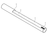
도 1은 본 발명의 일 실시예에 따른 양방향 혈류 유도가 가능한 대퇴동맥 캐뉼러의 끝단부 사시도
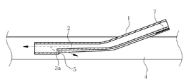
도 2는 상기 도 1의 캐뉼러를 대퇴동맥에 삽입하였을 때의 종단면도
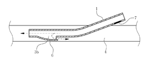
도 3은 상기 도 1의 캐뉼러를 대퇴동맥에 삽입하였을 때의 횡단면도
도 4는 본 발명의 다른 실시예에 따른 양방향 혈류 유도가 가능한 대퇴동맥 캐뉼러의 끝단부 사시도
도 5는 상기 도 4의 캐뉼러를 대퇴동맥에 삽입하였을 때의 종단면도FIG. 1 is a perspective view of an end portion of a femoral artery cannula capable of inducing bidirectional blood flow according to an embodiment of the present invention.
Fig. 2 is a longitudinal sectional view of the cannula of Fig. 1 when the cannula is inserted into the femoral artery
Figure 3 is a cross-sectional view of the cannula of Figure 1 when inserted into the femoral artery;
FIG. 4 is a perspective view of an end portion of a femoral artery cannula capable of inducing bidirectional blood flow according to another embodiment of the present invention.
5 is a longitudinal sectional view when the cannula of FIG. 4 is inserted into the femoral artery
이하, 본 발명에 따른 양방향 혈류 유도가 가능한 대퇴동맥 캐뉼러의 바람직한 실시예를 첨부한 도면을 참조로 하여 상세히 설명한다. 본 발명은 이하에서 개시되는 실시예에 한정되는 것이 아니라 서로 다른 다양한 형태로 구현될 수 있으며, 단지 본 실시예는 본 발명의 개시가 완전하도록 하며 통상의 지식을 가진 자에게 발명의 범주를 완전하게 알려주기 위하여 제공되는 것이다.Hereinafter, preferred embodiments of a femoral artery cannula capable of inducing bidirectional blood flow according to the present invention will be described in detail with reference to the accompanying drawings. It is to be understood that the present invention is not limited to the disclosed embodiments, but may be embodied in many different forms and should not be construed as limited to the embodiments set forth herein. Rather, these embodiments are provided so that this disclosure will be thorough and complete, It is provided to inform.
도 1은 본 발명의 일 실시예에 따른 양방향 혈류 유도가 가능한 대퇴동맥 캐뉼러의 끝단부 사시도이고, 도 2는 상기 도 1의 캐뉼러를 대퇴동맥에 삽입하였을 때의 종단면도이며, 도 3은 상기 도 1의 캐뉼러를 대퇴동맥에 삽입하였을 때의 횡단면도를 도시한 것이다.FIG. 1 is an end perspective view of a femoral artery cannula capable of bidirectional blood flow guidance according to an embodiment of the present invention, FIG. 2 is a longitudinal sectional view when the cannula of FIG. 1 is inserted into a femoral artery, 1 shows a cross-sectional view of the cannula when the cannula is inserted into the femoral artery.
도 1 내지 도 3에 도시한 바와 같이, 본 발명의 일 실시예에 따른 양방향 혈류 유도가 가능한 대퇴동맥 캐뉼러는 대퇴동맥 삽관법(Femoral arterial cannulation)에 사용되는 상기 캐뉼러의 유연성이 있는 재료로 만들어진 캐뉼러 관(1) 끝단의 안쪽에 혈류 유도로(2)와 관통홀(3a)을 각각 형성한 것이다.As shown in FIGS. 1 to 3, a femoral artery cannula capable of inducing bidirectional blood flow according to an embodiment of the present invention is a flexible material of the cannula used for femoral arterial cannulation And the blood flow guiding passage 2 and the through hole 3a are formed inside the end of the manufactured
상기 혈류 유도로(2)는 캐뉼러 관(1) 끝단의 안쪽 둘레면에서부터 길이방향을 따라 반대편 끝단까지 이어지는 라운드형의 오목부, 즉 고랑 형태로 형성한 것으로, 도 3의 횡단면도를 보면 원 둘레의 일부분을 안쪽으로 눌러 꺼져 있는 형태로 되어 있다. 이러한 혈류 유도로(2)만 가지고 본 발명의 캐뉼러를 구성할 수도 있는데, 도 2 및 도 3을 참조하면 혈관(4)에 삽입되는 본 발명의 캐뉼러의 캐뉼러 관(1)의 끝단에서 앞쪽으로 진행하는 혈류의 일부가 상기 혈류 유도로(2)에 의해 역행할 수 있도록 되어 있다. 즉 혈관(4)의 내벽과 혈류 유도로(2) 사이에 상기 혈류 유도로(2)가 없을 때보다 더 큰 간격을 형성함으로써, 상기 큰 간격을 통해 캐뉼러 관(1)의 끝단에서 앞쪽으로 진행하던 혈류의 일부가 상기 혈류 유도로(2)를 타고 역행하여 진행할 수 있게 된다(화살표 방향).The blood flow guiding passage 2 is formed in the form of a round concave portion, that is, a concave portion extending from the inner circumferential surface of the end of the
이러한 혈류 유도로(2)는 캐뉼러 관(1) 끝단 안쪽의 둘레면 일부를 안쪽으로 눌러 형성한 것이므로 서로 크고 작은 내경, 예를 들어 larger diameter lumen과 smaller diameter lumen을 형성하게 되어, 상기 캐뉼러 관(1)의 끝단 방향에서 혈류 유도로(2)와 캐뉼러 관(1) 사이의 경계부위에 수직단차를 형성하게 되고, 상기 관통홀(3a)은 이러한 수직 단차의 수직면에 형성한 것이다. 따라서 혈류 유도로(2)에 의한 작은 내경(smaller diameter lumen)의 캐뉼러 관(1) 내부에서 끝단의 큰 내경(larger diameter lumen)의 캐뉼러 관(1) 쪽, 즉 캐뉼러 관(1)의 안쪽에서부터 상기 캐뉼러 관(1)의 끝단을 빠져나와 심장이나 폐 쪽으로 진행하는 혈류의 일부가 상기 관통홀(3a) 부위에서 U턴하여 빠져나가게 된다. 이와 동시에 관통홀(3a)을 통해 빠져나온 혈류의 일부는 혈류 유도로(2)를 타고 역행하여 진행함으로써 하지(下肢) 말단, 즉 다리 말단에도 혈액을 공급하게 된다(화살표 방향).Since the blood flow guiding path 2 is formed by pushing inward a part of the circumferential surface of the inside of the end of the
한편, 도 2에 도시한 바와 같이, 상기 관통홀(3a) 상단의 캐뉼러 관(1) 일부가 혈류 유도로(2) 방향으로 돌출하면서 연장되어 유도 외벽(5)을 형성할 수도 있다. 이러한 유도 외벽(5)은 관통홀(3a)을 빠져나온 혈류의 일부가 상기 유도 외벽(5)을 타고 혈류 유도로(2) 쪽으로 안정적으로 진행할 수 있도록 안내하는 일종의 안내 벽의 역할을 하게 된다. 따라서 상기한 수직단차는 관통홀(3a)을 포함한 유도 외벽(5)이라 할 수 있다.2, a part of the
이러한 관통홀(3a)은 보통 5∼8㎜ 정도의 내경을 갖는 캐뉼러에서 2∼3㎜ 정도의 내경을 갖는 것이 혈류의 안정적인 역행을 위해 바람직하다.It is preferable that the through-hole 3a has an inner diameter of about 2 to 3 mm in a cannula having an inner diameter of about 5 to 8 mm, in order to stably reverse the blood flow.
이와 같은 상기 캐뉼러 관(1)을 혈관 삽입부를 통해 혈관(4) 내로 삽입할 때에는 상기 혈류 유도로(2)에 의해 형성된 수직단차가 혈관 삽입부의 아래쪽에 위치하므로 문제가 없다. 그러나 상기 캐뉼러 관(1)을 인출하고자 할 때에는 상기 수직단차가 혈관 삽입부의 혈관 벽에 걸려 잘 인출되지 않을 수 있으므로, 상기 수직단차가 혈관 삽입부 쪽에 위치하여 이를 통해 인출될 수 있도록 상기 캐뉼러 관(1)을 회전시키는 것이 필요하다. 이를 위해서 혈관(4)의 바깥쪽에 위치하는 캐뉼러 관(1)의 둘레면 소정 부위에 수직단차와 함께 상기 혈류 유도로(2)가 위치하는 부위를 표시해주도록 한다. 이러한 표시는 혈류 유도로(2)가 위치하는 부위와 반대편의 둘레면 위치에 캐뉼러 관(1)의 색과 대비되는 서로 다른 색깔이나 특정 모양의 표시를 각각 하거나, 상기 혈류 유도로(2)가 위치하는 부위의 둘레면에만 캐뉼러 관(1)의 색과 대비되는 색깔이나 특정 모양의 표시(7)를 할 수도 있다.When the
도 4는 본 발명의 다른 실시예에 따른 대퇴동맥 하지 말단 방향을 포함한 양방향 혈류를 위한 캐뉼러의 끝단부 사시도이고, 도 5는 상기 도 4의 캐뉼러를 대퇴동맥에 삽입하였을 때의 종단면도를 도시한 것이다.FIG. 4 is a perspective view of an end portion of a cannula for bidirectional blood flow including a lower end of the femoral artery according to another embodiment of the present invention, and FIG. 5 is a longitudinal sectional view of the cannula of FIG. Respectively.
도 4 및 도 5에 도시한 바와 같이, 본 발명의 다른 실시예에 따른 대퇴동맥 하지 말단 방향을 포함한 양방향 혈류를 위한 캐뉼러는 대퇴동맥 삽관법(Femoral arterial cannulation)에 사용되는 유연성이 있는 재료로 만들어진 상기 캐뉼러의 캐뉼러 관(1) 끝단 안쪽에 관통홀(3b)과 유도 커버(6)를 각각 형성한 것이다.As shown in FIGS. 4 and 5, the cannula for bidirectional blood flow including the distal end of the femoral artery according to another embodiment of the present invention is a flexible material used for femoral arterial cannulation And a through hole (3b) and an inductive cover (6) are formed inside the end of the cannula tube (1) of the formed cannula.
상기 관통홀(3b)은 캐뉼러 관(1) 끝단 안쪽의 둘레 면 일부에 상기한 일 실시예의 캐뉼러의 관통홀(3a)보다 크게 형성되며, 상기 캐뉼러 관(1) 끝단의 반대 방향을 향해 비스듬히 형성하는 것이 혈류의 안정적인 역행을 위해 바람직하다.The
상기 유도 커버(6)는 상기 관통홀(3b)에서 상부로 일정거리를 두고 비스듬히 덮도록 돌출 형성한 것으로, 캐뉼러 관(1)의 끝단 쪽을 향해 기울어져 형성됨으로써 반대편 쪽은 개방된 형태로 구성되어 있다.The
이와 같이 상기 유도 커버(6)를 비스듬히 기울여 형성함으로써 혈관 삽입부를 통해 혈관(4) 내로 캐뉼러 관(1)을 삽입할 때 무리 없이 삽입될 수 있게 된다. 다만 캐뉼러 관(1)을 혈관(4) 내에 삽입하여 사용할 때에 유도 커버(6)는 혈관 삽입부의 아래쪽에 위치하므로, 상기한 일 실시예에서의 캐뉼러에서와 같이 상기 유도 커버(6)가 혈관 삽입부 쪽에 위치하여 이를 통해 인출될 수 있도록 캐뉼러 관(1)을 회전시키는 것이 필요하다. 이를 위해서 여기에서도 혈관(4)의 바깥쪽에 위치하는 캐뉼러 관(1)의 둘레면 소정 부위에 상기 유도 커버(6)가 위치하는 부위를 표시해주도록 한다. 이러한 표시는 유도 커버(6)가 위치하는 부위와 반대편의 둘레면 위치에 캐뉼러 관(1)의 색과 대비되는 서로 다른 색깔이나 특정 모양의 표시를 각각 하거나, 상기 유도 커버(6)가 위치하는 부위의 둘레면에만 캐뉼러 관(1)의 색과 대비되는 색깔이나 특정 모양의 표시(7)를 할 수도 있다.When the
한편 상기한 바와 같이 캐뉼러 관(1)을 유도 커버(6)와 함께 혈관 삽입부를통해 혈관 밖으로 인출할 때, 도 4 및 도 5에 도시한 바와 같이, 상기 유도 커버(6)의 끝단 부위를 안쪽으로 약간 구부리는 것이 안전한 인출을 위해 바람직하다. 즉 유도 커버(6)의 끝단을 안쪽으로 약간 구부리면 캐뉼러 관(1)을 인출할 때 상기 유도 커버(6)가 혈관에 걸려 인출을 어렵게 하는 문제를 간단하게 해결할 수 있다.4 and 5, when the
이러한 관통홀(3b)과 유도 커버(6)에 의해 상기한 일 실시예의 혈류 유도로(2)와 관통홀(3a)에서와 같이 캐뉼러 관(1)을 혈관(4)에 삽입하여 혈액을 공급하면, 캐뉼러 관(1)의 안쪽에서부터 상기 캐뉼러 관(1)의 끝단을 빠져나와 심장이나 폐 쪽으로 진행하는 혈류의 일부가 상기 관통홀(3b) 부위에서 U턴하여 빠져나가게 된다. 이와 동시에 관통홀(3b)을 통해 빠져나온 혈류의 일부는 유도 커버(6)에 의해 안내되면서 역행하여 진행함으로써 말단의 다리에도 혈액을 공급하게 된다(화살표 방향).By inserting the
상기 캐뉼러(1)의 재료에 있어서는 환자의 신체 내부로 삽입하기에 적절한 재료로 구성될 수 있는데, 예를 들면, 세라막, 금속, 폴리머 등이 사용될 수 있으나, 환자의 체내에 장기가 있을 수 있고 생체호환적(biocompatible) 동시에 환자의 체내에 주입된 후 부드럽게 할 수 있도록 유연성이 있는 플라스틱 재료인 폴리머 종류가 적합할 수 있다. 상기 폴리머 재료는 예를 들어, 실리콘, 폴리카보네이트, 실리콘이 섞인 우레탄, 폴리스티렌-폴리이소부틸렌-폴리스티렌(SIBS)과 같은 것들을 사용할 수 있다.The material of the
또한 상기 캐뉼러(1)의 내외 표면은 측벽을 통해 혈류가 유동하는 것을 방지하고 혈전 응고 등을 고려하여 가요성 외피를 입히는 코팅을 하는 것이 바람직한데, 이러한 가요성 외피는 예를 들어 탄성중합체 외피와 같은 다양한 재료로 만들어질 수 있다. 또한 상기 코팅은 보통 중합체(폴리머) 용액 내에 침지하여 수행하게 되는데, 사용될 수 있는 중합체에는, 비제한적인 예로서, 생체적합성 중합체, 예를 들어 폴리비닐 클로라이드, 폴리올레핀(예를 들어, 폴리에틸렌, 폴리프로필렌, 에틸렌-비닐아세테이트 공중합체), 폴리아미드, 폴리에스테르(예를 들어, 폴리에틸렌 테레프탈레이트(PET), 폴리부틸렌 테레프탈레이트), 폴리우레탄, 폴리스티렌 수지, 불소계 수지(예를 들어, 폴리테트라플루오로에틸렌, 에틸렌-테트라플루오로에틸렌 공중합체), 폴리이미드 등; 및 다양한 탄성중합체, 예를 들어 폴리우레탄계 탄성중합체, 폴리에스테르계 탄성중합체, 폴리올레핀계 탄성중합체, 폴리아미드계 탄성중합체, 실리콘 고무, 라텍스 고무 및 이들의 조합이 포함된다.The inner and outer surfaces of the
상기한 캐뉼러의 재료 또는 코팅은 세포 또는 플라그가 그 위에 성장하거나 부착되는 것을 방지할 수 있다.The material or coating of the cannula can prevent the cell or plaque from growing or attaching thereon.
이상과 같이 본 발명에 따른 양방향 혈류 유도가 가능한 대퇴동맥 캐뉼러에 대해서 예시한 도면을 참조로 하여 설명하였으나, 본 명세서에 개시된 실시예와 도면에 의해 본 발명이 한정되는 것은 아니며, 본 발명의 기술사상의 범위 내에서 당업자에 의해 다양한 변형이 이루어질 수 있음은 물론이다.As described above, the femoral artery cannula capable of inducing bidirectional blood flow according to the present invention has been described with reference to the drawings. However, the present invention is not limited to the embodiments and the drawings disclosed herein, It will be understood by those skilled in the art that various changes in form and details may be made therein without departing from the scope of the invention.
1 : 캐뉼러 관
2 : 혈류 유도로
3a,3b : 관통홀
4 : 혈관
5 : 유도 외벽
6 : 유도 커버
7 : 혈류 유도로 또는 유도 커버의 위치를 나타내는 표시1: cannula tube 2: blood flow guide path
3a, 3b: through hole 4: blood vessel
5: induction outer wall 6: induction cover
7: Indication of the position of the blood guide path or guide cover
Claims (10)
상기 캐뉼러 관 끝단 안쪽의 둘레 면 소정부위에서부터 길이방향을 따라 반대편 끝단까지 오목부로 형성되는 혈류 유도로를 포함한 것을 특징으로 하는 양방향 혈류 유도가 가능한 대퇴동맥 캐뉼러.In a cannula having a cannula tube inserted into a vein of a femoral artery,
And a blood flow guiding passage extending from a predetermined portion of the circumferential surface inside the end of the cannula to an opposite end along the longitudinal direction.
상기 캐뉼러 관 끝단 방향에서 혈류 유도로와 캐뉼러 관 사이의 경계 부위에 형성한 관통홀을 더 포함하는 것을 특징으로 하는 양방향 혈류 유도가 가능한 대퇴동맥 캐뉼러.The method according to claim 1,
Further comprising a through hole formed at a boundary portion between the blood flow guiding passage and the cannula tube in the direction of the end of the cannula tube.
상기 관통홀의 상단에서 혈류 유도로의 방향으로 돌출하여 연장되는 유도 외벽을 형성한 것을 특징으로 하는 양방향 혈류 유도가 가능한 대퇴동맥 캐뉼러.3. The method of claim 2,
And an induction outer wall protruding from the upper end of the through hole in the direction of the blood flow guiding path is formed.
상기 캐뉼러 관은 5∼8㎜의 내경을 갖는 캐뉼러인 것을 특징으로 하는 양방향 혈류 유도가 가능한 대퇴동맥 캐뉼러.The method according to claim 1,
Wherein the cannula is a cannula having an inner diameter of 5 to 8 mm.
상기 관통홀은 2∼3㎜의 내경으로 형성되는 것을 특징으로 하는 양방향 혈류 유도가 가능한 대퇴동맥 캐뉼러.5. The method of claim 4,
Wherein the through-hole is formed with an inner diameter of 2 to 3 mm.
상기 혈류 유도로는 고랑 형태의 라운드형인 것을 특징으로 하는 양방향 혈류 유도가 가능한 대퇴동맥 캐뉼러.The method according to claim 1,
Wherein the blood flow guiding passage is a round shape in the form of a trough.
상기 캐뉼러 관 끝단 안쪽의 둘레 면 소정부위에 관통홀이 형성되고, 상기 관통홀 상부를 덮어 혈류를 안내하는 유도 커버가 관통홀 상부에 형성된 것을 특징으로 하는 양방향 혈류 유도가 가능한 대퇴동맥 캐뉼러.In a cannula having a cannula tube inserted into a vein of a femoral artery,
Wherein a through hole is formed in a predetermined portion of a circumferential surface inside the end of the cannula tube and an inductive cover covering the upper portion of the through hole and guiding the blood flow is formed on the upper portion of the through hole.
상기 유도 커버는 캐뉼러 관 끝단을 향해 비스듬히 기울여 형성한 것을 특징으로 하는 양방향 혈류 유도가 가능한 대퇴동맥 캐뉼러.8. The method of claim 7,
Wherein the guide cover is inclined at an angle to the end of the cannula tube.
상기 유도 커버의 끝단 일부를 안쪽으로 구부려 형성한 것을 특징으로 하는 양방향 혈류 유도가 가능한 대퇴동맥 캐뉼러.9. The method of claim 8,
Wherein the guide cover is formed by bending a part of an end of the guide cover inward.
대퇴동맥의 바깥쪽에 위치하는 상기 캐뉼러 관 둘레면에 상기 혈류 유도로가 위치한 부위 또는 상기 유도 커버가 위치한 부위를 구별할 수 있는 표시를 하도록 한 것을 특징으로 하는 양방향 혈류 유도가 가능한 대퇴동맥 캐뉼러.The method according to claim 1 or 7,
Characterized in that an indication is provided on the peripheral surface of the cannula tube located on the outer side of the femoral artery to distinguish the site where the blood guide path is located or the site where the induction cover is located. .
Priority Applications (3)
| Application Number | Priority Date | Filing Date | Title |
|---|---|---|---|
| KR1020150026099A KR20160103474A (en) | 2015-02-24 | 2015-02-24 | Femoral arterial Cannula capable of guidance of bidirectional flow |
| US15/551,613 US10449286B2 (en) | 2015-02-24 | 2016-02-24 | Femoral arterial cannula capable of guiding bidirectional perfusion flow |
| PCT/KR2016/001772 WO2016137212A1 (en) | 2015-02-24 | 2016-02-24 | Femoral arterial cannula capable of guiding bidirectional perfusion flow |
Applications Claiming Priority (1)
| Application Number | Priority Date | Filing Date | Title |
|---|---|---|---|
| KR1020150026099A KR20160103474A (en) | 2015-02-24 | 2015-02-24 | Femoral arterial Cannula capable of guidance of bidirectional flow |
Related Child Applications (1)
| Application Number | Title | Priority Date | Filing Date |
|---|---|---|---|
| KR1020190091242A Division KR102032447B1 (en) | 2019-07-26 | 2019-07-26 | Femoral arterial Cannula capable of guidance of bidirectional flow |
Publications (1)
| Publication Number | Publication Date |
|---|---|
| KR20160103474A true KR20160103474A (en) | 2016-09-01 |
Family
ID=56789752
Family Applications (1)
| Application Number | Title | Priority Date | Filing Date |
|---|---|---|---|
| KR1020150026099A Ceased KR20160103474A (en) | 2015-02-24 | 2015-02-24 | Femoral arterial Cannula capable of guidance of bidirectional flow |
Country Status (3)
| Country | Link |
|---|---|
| US (1) | US10449286B2 (en) |
| KR (1) | KR20160103474A (en) |
| WO (1) | WO2016137212A1 (en) |
Cited By (3)
| Publication number | Priority date | Publication date | Assignee | Title |
|---|---|---|---|---|
| WO2018169503A1 (en) | 2017-03-17 | 2018-09-20 | T. C. Istanbul Medipol Universitesi | A femoral arterial ecmo (extracorporeal membrane oxygenation) cannula |
| KR20210031227A (en) * | 2019-09-11 | 2021-03-19 | 인제대학교 산학협력단 | Medical conduit to enable bidirectional fluid flow |
| CN113082452A (en) * | 2020-01-08 | 2021-07-09 | 四川大学华西医院 | Femoral artery cannula |
Families Citing this family (16)
| Publication number | Priority date | Publication date | Assignee | Title |
|---|---|---|---|---|
| FR3058642B1 (en) * | 2016-11-15 | 2023-03-10 | Hopitaux Paris Assist Publique | CANNULA AND OXYGENATION SYSTEM BY EXTRACORPORAL MEMBRANE COMPRISING SUCH CANNULA |
| US11364333B2 (en) | 2017-10-10 | 2022-06-21 | University Of Maryland, Baltimore | Bidirectional flow catheter |
| EP3735996B1 (en) | 2019-05-07 | 2023-09-27 | Free Life Medical GmbH | Bi-directional perfusion cannula |
| IT201900016466A1 (en) * | 2019-09-17 | 2021-03-17 | Andrea Ugolini | CANNULA FOR MEDICAL USE, IN PARTICULAR FOR INSERTION IN ARTERIES. |
| WO2021078446A1 (en) | 2019-10-22 | 2021-04-29 | Medtronic, Inc. | Bi-directional perfusion system |
| USD975844S1 (en) | 2019-11-06 | 2023-01-17 | Free Life Medical Gmbh | Cannula |
| FR3103109B1 (en) * | 2019-11-18 | 2024-11-29 | Novaflow | Bidirectional arterial cannula for extracorporeal membrane oxygenation and method of using such a cannula |
| TWI724682B (en) * | 2019-12-11 | 2021-04-11 | 林伯彥 | Bidirectional vascular tube device |
| KR102440811B1 (en) * | 2020-11-26 | 2022-09-06 | 아주대학교산학협력단 | Blood oxygen saturation measurement system |
| CN112704799B (en) * | 2020-12-22 | 2022-09-16 | 义乌市宏博机械科技有限公司 | Femoral artery perfusion device for medical cardiac surgery |
| EP4108268A1 (en) | 2021-06-22 | 2022-12-28 | Jawad Salman | Bi-directional cannula |
| CN114099815A (en) * | 2021-09-10 | 2022-03-01 | 北京航空航天大学 | Intubation tube, blood transfusion pipeline and extracorporeal membrane oxygenation system |
| US20230099710A1 (en) * | 2021-09-28 | 2023-03-30 | Joseph A. Ramirez-Cárdenas | Vascular access reversing device and methods of use thereof |
| CN115006685B (en) * | 2022-04-19 | 2023-06-02 | 中国医学科学院阜外医院 | Aortic perfusion tube capable of preventing blood loss |
| CN115089796A (en) * | 2022-06-16 | 2022-09-23 | 北京航空航天大学 | Femoral artery cannulation |
| CN115531646A (en) * | 2022-10-20 | 2022-12-30 | 山东威高拓威医疗器械有限公司 | A peripheral arterial cannula |
Citations (3)
| Publication number | Priority date | Publication date | Assignee | Title |
|---|---|---|---|---|
| KR101122334B1 (en) | 2004-11-05 | 2012-03-28 | 감브로 룬디아 아베 | Catheter for vascular access and method for manufacturing the same |
| US20120259273A1 (en) | 2011-04-05 | 2012-10-11 | Mtmm Pty Ltd | Bi-Directional Perfusion Cannula |
| KR101337164B1 (en) | 2012-01-31 | 2013-12-05 | 중앙대학교 산학협력단 | Cannula device |
Family Cites Families (16)
| Publication number | Priority date | Publication date | Assignee | Title |
|---|---|---|---|---|
| US5569182A (en) * | 1990-01-08 | 1996-10-29 | The Curators Of The University Of Missouri | Clot resistant multiple lumen catheter and method |
| US5171218A (en) * | 1992-01-02 | 1992-12-15 | Trustees Of Boston University | Bidirectional femoral arterial cannula |
| US5425724A (en) * | 1994-04-26 | 1995-06-20 | Akins; Cary W. | Aortic perfusion cannula |
| WO1997039789A1 (en) * | 1996-04-22 | 1997-10-30 | Medtronic, Inc. | Two-stage angled venous cannula |
| US5800408A (en) | 1996-11-08 | 1998-09-01 | Micro Therapeutics, Inc. | Infusion device for distributing infusate along an elongated infusion segment |
| US5928192A (en) * | 1997-07-24 | 1999-07-27 | Embol-X, Inc. | Arterial aspiration |
| US6099506A (en) | 1997-09-26 | 2000-08-08 | Macoviak; John A. | Introducer and perfusion cannula |
| US5976114A (en) * | 1998-04-30 | 1999-11-02 | Medtronic, Inc. | Aortic cannula with reduced velocity flow-through tip |
| US6186981B1 (en) * | 1999-03-23 | 2001-02-13 | Peter Cho | Cavo-atrial cannula |
| US6626872B1 (en) * | 2000-09-12 | 2003-09-30 | Jose A. Navia | Perfusion cannula |
| AU2010255323B2 (en) * | 2009-06-04 | 2014-10-16 | Cardiogard Medical Ltd. | Arterial device, system and method |
| US9220872B2 (en) * | 2010-04-13 | 2015-12-29 | Sundaram Ravikumar | Bidirectional vascular introducer sheath |
| US8535294B2 (en) * | 2011-06-01 | 2013-09-17 | Fischell Innovations Llc | Carotid sheath with flexible distal section |
| US9314328B2 (en) | 2011-08-16 | 2016-04-19 | W. L. Gore & Associates, Inc. | Branched stent graft device and deployment |
| WO2015116004A1 (en) * | 2014-01-30 | 2015-08-06 | Singapore Health Services Pte Ltd | Arterial sheath which allows distal perfusion within a cannulated vessel |
| US9981119B2 (en) * | 2014-10-29 | 2018-05-29 | Edwards Lifesciences Corporation | Bi-directional cannula |
-
2015
- 2015-02-24 KR KR1020150026099A patent/KR20160103474A/en not_active Ceased
-
2016
- 2016-02-24 WO PCT/KR2016/001772 patent/WO2016137212A1/en not_active Ceased
- 2016-02-24 US US15/551,613 patent/US10449286B2/en active Active
Patent Citations (3)
| Publication number | Priority date | Publication date | Assignee | Title |
|---|---|---|---|---|
| KR101122334B1 (en) | 2004-11-05 | 2012-03-28 | 감브로 룬디아 아베 | Catheter for vascular access and method for manufacturing the same |
| US20120259273A1 (en) | 2011-04-05 | 2012-10-11 | Mtmm Pty Ltd | Bi-Directional Perfusion Cannula |
| KR101337164B1 (en) | 2012-01-31 | 2013-12-05 | 중앙대학교 산학협력단 | Cannula device |
Cited By (4)
| Publication number | Priority date | Publication date | Assignee | Title |
|---|---|---|---|---|
| WO2018169503A1 (en) | 2017-03-17 | 2018-09-20 | T. C. Istanbul Medipol Universitesi | A femoral arterial ecmo (extracorporeal membrane oxygenation) cannula |
| KR20210031227A (en) * | 2019-09-11 | 2021-03-19 | 인제대학교 산학협력단 | Medical conduit to enable bidirectional fluid flow |
| CN113082452A (en) * | 2020-01-08 | 2021-07-09 | 四川大学华西医院 | Femoral artery cannula |
| CN113082452B (en) * | 2020-01-08 | 2023-02-17 | 西安西京医疗用品有限公司 | Femoral artery cannula |
Also Published As
| Publication number | Publication date |
|---|---|
| US10449286B2 (en) | 2019-10-22 |
| US20180043085A1 (en) | 2018-02-15 |
| WO2016137212A1 (en) | 2016-09-01 |
Similar Documents
| Publication | Publication Date | Title |
|---|---|---|
| KR20160103474A (en) | Femoral arterial Cannula capable of guidance of bidirectional flow | |
| KR102032447B1 (en) | Femoral arterial Cannula capable of guidance of bidirectional flow | |
| US5509900A (en) | Apparatus and method for retaining a catheter in a blood vessel in a fixed position | |
| JP6738467B2 (en) | VA ECMO for pulmonary artery ventilation | |
| AU2007200797B2 (en) | A pump-inflow-cannula, a pump-outflow-cannula and a blood managing system | |
| US10751522B2 (en) | Bi-directional cannula | |
| US20190255245A1 (en) | Method of Assisting a Heart Using a Dual Lumen Cannula | |
| US10456518B2 (en) | Arterial cannula which allows perfusion along opposing directions within a cannulated vessel | |
| JPH07502443A (en) | Bidirectional femoral artery cannula | |
| CN117137591A (en) | puncture system | |
| JP2004528139A (en) | Multilumen catheter to minimize limb ischemia | |
| US12453809B2 (en) | Dual lumen cannula with expandable lumen | |
| CN114502211A (en) | Bidirectional perfusion system | |
| WO2015012240A1 (en) | Antegrade blood transmission cannula | |
| US20220184292A1 (en) | Dual lumen drainage cannula with single outlet | |
| JP6813570B2 (en) | Percutaneous catheter | |
| US8529514B2 (en) | Cannula with removable sleeve | |
| US11395869B2 (en) | Arterial cannula which allows perfusion along opposing directions within a cannulated vessel | |
| US20250360297A1 (en) | Vascular access reversing device and method for treating endovascular infarction | |
| US20230381470A1 (en) | Balloon catheter | |
| JP2017018218A (en) | Medical tubular body | |
| JP2002119597A (en) | Indwelling balloon intracatheter |
Legal Events
| Date | Code | Title | Description |
|---|---|---|---|
| PA0109 | Patent application |
Patent event code: PA01091R01D Comment text: Patent Application Patent event date: 20150224 |
|
| PG1501 | Laying open of application | ||
| A201 | Request for examination | ||
| PA0201 | Request for examination |
Patent event code: PA02012R01D Patent event date: 20170106 Comment text: Request for Examination of Application Patent event code: PA02011R01I Patent event date: 20150224 Comment text: Patent Application |
|
| E902 | Notification of reason for refusal | ||
| PE0902 | Notice of grounds for rejection |
Comment text: Notification of reason for refusal Patent event date: 20180827 Patent event code: PE09021S01D |
|
| AMND | Amendment | ||
| E601 | Decision to refuse application | ||
| PE0601 | Decision on rejection of patent |
Patent event date: 20190429 Comment text: Decision to Refuse Application Patent event code: PE06012S01D Patent event date: 20180827 Comment text: Notification of reason for refusal Patent event code: PE06011S01I |
|
| AMND | Amendment | ||
| PX0901 | Re-examination |
Patent event code: PX09011S01I Patent event date: 20190429 Comment text: Decision to Refuse Application Patent event code: PX09012R01I Patent event date: 20181227 Comment text: Amendment to Specification, etc. |
|
| PX0601 | Decision of rejection after re-examination |
Comment text: Decision to Refuse Application Patent event code: PX06014S01D Patent event date: 20190627 Comment text: Amendment to Specification, etc. Patent event code: PX06012R01I Patent event date: 20190529 Comment text: Decision to Refuse Application Patent event code: PX06011S01I Patent event date: 20190429 Comment text: Amendment to Specification, etc. Patent event code: PX06012R01I Patent event date: 20181227 Comment text: Notification of reason for refusal Patent event code: PX06013S01I Patent event date: 20180827 |
|
| PA0107 | Divisional application |
Comment text: Divisional Application of Patent Patent event date: 20190726 Patent event code: PA01071R01D |