JP5918511B2 - Structure of the shock absorber mounting part of the vehicle - Google Patents
Structure of the shock absorber mounting part of the vehicle Download PDFInfo
- Publication number
- JP5918511B2 JP5918511B2 JP2011253523A JP2011253523A JP5918511B2 JP 5918511 B2 JP5918511 B2 JP 5918511B2 JP 2011253523 A JP2011253523 A JP 2011253523A JP 2011253523 A JP2011253523 A JP 2011253523A JP 5918511 B2 JP5918511 B2 JP 5918511B2
- Authority
- JP
- Japan
- Prior art keywords
- panel
- shock absorber
- fill
- fill house
- quarter panel
- Prior art date
- Legal status (The legal status is an assumption and is not a legal conclusion. Google has not performed a legal analysis and makes no representation as to the accuracy of the status listed.)
- Active
Links
- 239000006096 absorbing agent Substances 0.000 title claims description 39
- 230000035939 shock Effects 0.000 title claims description 39
- 239000000446 fuel Substances 0.000 claims description 22
- 239000000945 filler Substances 0.000 claims description 15
- 230000002787 reinforcement Effects 0.000 claims description 4
- 230000003014 reinforcing effect Effects 0.000 claims 2
- 230000000903 blocking effect Effects 0.000 description 3
- 239000000725 suspension Substances 0.000 description 3
- 230000008878 coupling Effects 0.000 description 2
- 238000010168 coupling process Methods 0.000 description 2
- 238000005859 coupling reaction Methods 0.000 description 2
- 230000005540 biological transmission Effects 0.000 description 1
- 238000007796 conventional method Methods 0.000 description 1
- 238000010586 diagram Methods 0.000 description 1
- 238000009434 installation Methods 0.000 description 1
- 238000012986 modification Methods 0.000 description 1
- 230000004048 modification Effects 0.000 description 1
- 230000000149 penetrating effect Effects 0.000 description 1
- 239000012779 reinforcing material Substances 0.000 description 1
- 239000003381 stabilizer Substances 0.000 description 1
Images


Classifications
-
- B—PERFORMING OPERATIONS; TRANSPORTING
- B62—LAND VEHICLES FOR TRAVELLING OTHERWISE THAN ON RAILS
- B62D—MOTOR VEHICLES; TRAILERS
- B62D25/00—Superstructure or monocoque structure sub-units; Parts or details thereof not otherwise provided for
- B62D25/08—Front or rear portions
- B62D25/16—Mud-guards or wings; Wheel cover panels
-
- B—PERFORMING OPERATIONS; TRANSPORTING
- B62—LAND VEHICLES FOR TRAVELLING OTHERWISE THAN ON RAILS
- B62D—MOTOR VEHICLES; TRAILERS
- B62D25/00—Superstructure or monocoque structure sub-units; Parts or details thereof not otherwise provided for
- B62D25/08—Front or rear portions
- B62D25/088—Details of structures as upper supports for springs or dampers
-
- B—PERFORMING OPERATIONS; TRANSPORTING
- B60—VEHICLES IN GENERAL
- B60G—VEHICLE SUSPENSION ARRANGEMENTS
- B60G13/00—Resilient suspensions characterised by arrangement, location or type of vibration dampers
- B60G13/001—Arrangements for attachment of dampers
- B60G13/003—Arrangements for attachment of dampers characterised by the mounting on the vehicle body or chassis of the damper unit
-
- B—PERFORMING OPERATIONS; TRANSPORTING
- B62—LAND VEHICLES FOR TRAVELLING OTHERWISE THAN ON RAILS
- B62D—MOTOR VEHICLES; TRAILERS
- B62D21/00—Understructures, i.e. chassis frame on which a vehicle body may be mounted
- B62D21/11—Understructures, i.e. chassis frame on which a vehicle body may be mounted with resilient means for suspension, e.g. of wheels or engine; sub-frames for mounting engine or suspensions
-
- B—PERFORMING OPERATIONS; TRANSPORTING
- B60—VEHICLES IN GENERAL
- B60G—VEHICLE SUSPENSION ARRANGEMENTS
- B60G2204/00—Indexing codes related to suspensions per se or to auxiliary parts
- B60G2204/10—Mounting of suspension elements
- B60G2204/12—Mounting of springs or dampers
- B60G2204/128—Damper mount on vehicle body or chassis
Description
本発明は、車両のショックアブソーバー装着部の構造に関するものであり、より詳細には、車両のリアショックアブソーバーと燃料フィラーネックが設置された部位の構造に関するものである。 The present invention relates to a structure of a shock absorber mounting portion of a vehicle, and more particularly to a structure of a portion of a vehicle where a rear shock absorber and a fuel filler neck are installed.
車両走行中に道路の条件によって発生するロードノイズ(ROAD NOISE)は、タイヤと懸架装置を通じて車体に伝わり、搭乗者に不快感を与えるようになる。このようなロードノイズの伝達は、懸架装置をなすショックアブソーバーが車体に装着された部位を通じて車体パネルを加振させることによるものであり、ショックアブソーバー装着部の剛性がロードノイズの絶縁及び遮断に非常に重要な役割をする。 Road noise (ROAD NOISE) generated due to road conditions while the vehicle is traveling is transmitted to the vehicle body through the tires and the suspension device, causing discomfort to the passenger. Such transmission of road noise is due to the vibration of the vehicle body panel through the part where the shock absorber that forms the suspension is mounted on the vehicle body, and the rigidity of the shock absorber mounting part is extremely useful for insulating and blocking road noise. To play an important role.
図1は、従来の車両のリア懸架装置をなすショックアブソーバー500が車体に装着された構造を示したものであり、図2は、フィルハウスインナーパネル502とクォーターパネル504を斜視図で示したものである。この図は、ショックアブソーバー500の上端が、燃料を注油する燃料フィラーネック506が設置された部位と接してマウンティングされなければならない車両の構造を示しているが、ショックアブソーバー500の上端は、マウンティングブラケット508を通じてフィルハウスインナーパネル502にマウンティングされて、フィルハウスインナーパネル502は、上端部がクォーターパネル504に接合され、燃料フィラーネック506は、ショックアブソーバー500に隣接した状態で前記クォーターパネル504を貫通して設置されている。
FIG. 1 shows a structure in which a shock absorber 500 constituting a rear suspension device of a conventional vehicle is mounted on a vehicle body, and FIG. 2 shows a perspective view of a fill house
マウンティングブラケット508は、燃料フィラーネック506と、これに連結される燃料ラインとの干渉がありうるなどの理由で、上端がフィルハウスインナーパネル502に垂直した接合面に結合される。このような結合構造は、ショックアブソーバー500に伝わるロードノイズに対する剛性において、マウンティングブラケット508がフィルハウスインナーパネル502に水平方向の接合面を有して結合されることに比べて、相対的に不利で十分な剛性を確保できないことがある。
The
ショックアブソーバーの装着構造としては、ショックアブソーバーとスタビライザーバーを、別のマウンティングブラケットを使用せずにローワーアーム上に直接一体に装着させて全体的な剛性の向上及び重量の減少が計れる懸架装置用ローワーアームアセンブリー〔特許文献1〕、ショックアブソーバーブラケットの締結部付近の応力集中を緩和し、車体への負担を軽減するショックアブソーバー取付け部構造〔特許文献2〕などの報告がある。 The shock absorber mounting structure includes a shock absorber and stabilizer bar that are mounted directly on the lower arm without using a separate mounting bracket, so that overall rigidity can be improved and weight can be reduced. There are reports of an arm assembly [Patent Document 1], a shock absorber mounting structure [Patent Document 2] that reduces stress concentration near the fastening portion of the shock absorber bracket, and reduces the load on the vehicle body.
上記問題点に鑑みて本発明の目的は、ショックアブソーバー上端が結合された部位の剛性を充分に確保することができるようにして、ロードノイズを効果的に遮断、絶縁して車両の騷音振動特性を改善する車両のショックアブソーバー装着部の構造を提供することにある。 In view of the above-described problems, the object of the present invention is to effectively cut off and insulate road noise so that the rigidity of the portion where the upper end of the shock absorber is coupled can be sufficiently secured. An object of the present invention is to provide a structure of a shock absorber mounting portion of a vehicle that improves characteristics.
上記の目的を達成するためになされた本発明に係る車両のショックアブソーバー装着部の構造は、クォーターパネルと、上端部がクォーターパネルに結合されて、フィルハウスを形成するフィルハウスインナーパネルと、フィルハウスインナーパネルの上側面とクォーターパネルに結合されて、フィルハウスインナーパネル及びクォーターパネルと共に閉空間を形成するインナーサポートメンバーと、クォーターパネルを中心にインナーサポートメンバーと対応するようにクォーターパネルと共に閉空間を形成するようにクォーターパネルに結合するアウトサポートメンバーと、上端部がフィルハウスインナーパネルに水平方向接合面をなして結合されてショックアブソーバーの上端を支持するマウンティングブラケットと、を有して構成されている。 In order to achieve the above object, the structure of the shock absorber mounting portion of the vehicle according to the present invention includes a quarter panel, a fill house inner panel in which an upper end portion is coupled to the quarter panel to form a fill house, Combined with the upper side of the house inner panel and the quarter panel, the inner support member forms a closed space with the fill house inner panel and the quarter panel, and the closed space with the quarter panel so as to correspond to the inner support member around the quarter panel. An out-support member that is coupled to the quarter panel so as to form an upper end, and a mounting bracket that supports the upper end of the shock absorber by coupling the upper end of the fill-house inner panel with a horizontal joint surface. To have.
本発明に係る車両のショックアブソーバー装着部の構造は、ショックアブソーバーの上端が車体にマウンティングされる部位が燃料フィラーネック及び燃料ラインと接するように位置する場合にも、ショックアブソーバー上端が結合される部位の剛性を充分に確保することができ、ロードノイズを効果的に遮断及び絶縁でき、車両の騷音振動を少なくすることができ、車両の商品価値を高めることができる。
また、本発明による車両のショックアブソーバー装着部の構造は、結果的にフィルハウス空間を二重隔膜構造で遮断するようになって、フィルハウス空間からの異物が車両内部に流入するのを遮断する役割もするようになる。
The structure of the shock absorber mounting portion of the vehicle according to the present invention is such that the upper end of the shock absorber is coupled even when the upper end of the shock absorber is positioned so as to contact the fuel filler neck and the fuel line. Can be sufficiently secured, road noise can be effectively blocked and insulated, vehicle noise and vibration can be reduced, and the commercial value of the vehicle can be increased.
In addition, the structure of the shock absorber mounting portion of the vehicle according to the present invention results in blocking the fill house space with a double diaphragm structure, thereby blocking foreign matters from the fill house space from flowing into the vehicle. Also comes to play a role.
図3〜7に本発明に係る車両のショックアブソーバー装着部の構造を図示している。本発明車両のショックアブソーバー装着部の構造は、クォーターパネル1と、上端部がクォーターパネル1に結合されてフィルハウスを形成するフィルハウスインナーパネル3と、フィルハウスインナーパネル3の上側面とクォーターパネル1に結合されて、フィルハウスインナーパネル3及びクォーターパネル1と共に閉空間を形成するインナーサポートメンバー5と、クォーターパネル1を中心にインナーサポートメンバー5と対応するようにクォーターパネル1と共に閉空間を形成してクォーターパネル1に結合したアウトサポートメンバー7と、上端部がフィルハウスインナーパネル3に水平方向接合面をなして結合され、ショックアブソーバーの上端を支持するマウンティングブラケット9を有して構成される。
3 to 7 show the structure of the shock absorber mounting portion of the vehicle according to the present invention. The structure of the shock absorber mounting portion of the vehicle of the present invention includes a
燃料フィラーネック11とこれに連結した燃料ラインは、フィルハウスインナーパネル3の上側面を通過して、インナーサポートメンバー5とアウトサポートメンバー7によって形成された閉空間を通じてアウトサポートメンバー7を貫通するように設置される。
The
すなわち、従来技術では、図1に示したようにフィルハウス上側空間をそのまま活用して燃料フィラーネックと燃料ラインが設置されるようにしていた。本発明では、フィルハウスインナーパネル3とクォーターパネル1によって形成されたフィルハウス空間を別に具備して、このフィルハウス空間上側にインナーサポートメンバー5とアウトサポートメンバー7を具備して、これらが形成する閉空間を活用して燃料フィラーネック11とこれに連結された燃料ラインの設置が可能であるようにしている。そして、マウンティングブラケット9の上端部を、フィルハウス空間を形成するフィルハウスインナーパネル3の下側面と水平な接合面で結合することで、ショックアブソーバーからマウンティングブラケット9に伝わったロードノイズに対してより強い剛性を与えるようにしたものである。
That is, in the prior art, as shown in FIG. 1, the fuel filler neck and the fuel line are installed using the space above the fill house as it is. In the present invention, a fill house space formed by the fill house
クォーターパネル1は、垂直面の下側にフィルハウスを形成するように外側に折曲された断面形状を有して、フィルハウスインナーパネル3は、上端部がクォーターパネル1の折曲部位に互いに垂直な接合面を形成して結合される。
The
すなわち、フィルハウスインナーパネル3は、従来とは異なり純粋にフィルハウス空間を形成するだけの構造で、クォーターパネル1の下側折曲部がフィルハウスインナーパネル3と共にフィルハウスを形成するようにしたものである。
That is, the fill house
インナーサポートメンバー5は、下端部がフィルハウスインナーパネル3の上側面に水平方向の接合面で結合され、上端部はクォーターパネル1の垂直面に垂直方向の接合面で結合され、アウトサポートメンバー7は、下端部がクォーターパネル1の折曲されてフィルハウスを形成する部位の上側面に水平方向の接合面で結合されて、上端部はクォーターパネル1の垂直面に垂直方向の接合面で結合する構造である。
The
マウンティングブラケット9の上端部は、フィルハウスインナーパネル3を中心にインナーサポートメンバー5の下端部がフィルハウスインナーパネル3に接合された部位に対応するように結合されて、フィルハウスインナーパネル3を中心に上下に重畳されて結合することで、マウンティングブラケット9から上下方向に作用する荷重及び振動に対してより強い剛性となるようにしている。
The upper end of the
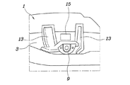
一方、図7を参照すると、フィルハウスインナーパネル3とクォーターパネル1が形成するフィルハウス内でフィルハウスインナーパネル3の下側面からクォーターパネル1の下側面に延長された形状で結合された複数個のフィルハウス補強材13をさらに具備して、マウンティングブラケット9は、フィルハウス補強材13の間に結合されて、両側部分がフィルハウス補強材13に重畳されて結合する構造を取って、より強い剛性が確保できるようにしている。
On the other hand, referring to FIG. 7, a plurality of members connected in a shape extending from the lower surface of the fill house
図7のフィルハウスインナーパネルに形成された穴15は、燃料フィラーネックまたはこれに連結される燃料ラインが通過するようにする穴である。
A
このように、ショックアブソーバーの上端を支持するマウンティングブラケット9の上端部が、フィルハウスインナーパネル3に水平方向の接合面で結合され、その両側がフィルハウス補強材13に重畳されて結合され、下側はフィルハウスインナーパネル3に垂直方向の接合面で結合され、フィルハウスインナーパネル3と共にまた他の閉空間を形成して結合するので、ショックアブソーバーから伝達する荷重や振動及びロードノイズに対して十分な支持剛性を確保することができる。これにより、ロードノイズに対して効果的に絶縁、遮断することができ、車両の騷音性能を改善することができ、さらに車両の商品価値を高めることができる。
In this way, the upper end portion of the
また、燃料フィラーネック11の設置のために、フィルハウスインナーパネル3とクォーターパネル1には穴が形成されるとフィルハウス空間から異物が車体内部まで浸透することがあるが、本発明による構造では、フィルハウスインナーパネル3とインナーサポートメンバー5、及びクォーターパネル1とアウトサポートメンバー7がそれぞれ二重構造を形成するようになり、これにより外部からの異物が車体内部まで浸透することがなくなる。
Further, if a hole is formed in the fill house
本発明は、特定の実施形態で図示して説明したが、以下の特許請求範囲によって提供される本発明の技術的思想を脱しない限度内で多様に改良、変形できることは当業者には自明であろう。 While the invention has been illustrated and described in specific embodiments, it will be apparent to those skilled in the art that various modifications and variations can be made without departing from the spirit of the invention provided by the following claims. I will.
1;クォーターパネル
3;フィルハウスインナーパネル
5;インナーサポートメンバー
7;アウトサポートメンバー
9;マウンティングブラケット
11;燃料フィラーネック
13;フィルハウス補強材
15;(フィルハウスインナーパネルに形成された)穴
500;ショックアブソーバー
502;フィルハウスインナーパネル
504;クォーターパネル
506;燃料フィラーネック
508;マウンティングブラケット
1;
Claims (5)
上端部が前記クォーターパネル(1)に結合されて、フィルハウスを形成するフィルハウスインナーパネル(3)と、
前記フィルハウスインナーパネル(3)の上側面と前記クォーターパネル(1)に結合されて、前記フィルハウスインナーパネル(3)及び前記クォーターパネル(1)と共に閉空間を形成するインナーサポートメンバー(5)と、
前記クォーターパネル(1)を中心に前記インナーサポートメンバー(5)と対応するように前記クォーターパネル(1)と共に閉空間を形成するように前記クォーターパネル(1)に結合するアウトサポートメンバー(7)と、
上端部が前記フィルハウスインナーパネル(3)に水平方向接合面をなして結合されてショックアブソーバーの上端を支持するマウンティングブラケット(9)と、を有して構成され、
燃料フィラーネック(11)とこれに連結される燃料ラインは、前記フィルハウスインナーパネル(3)の上側面を通過して、前記インナーサポートメンバー(5)と前記アウトサポートメンバー(7)によって形成する閉空間を通じて前記アウトサポートメンバー(7)を貫通して設置されたことを特徴とする車両のショックアブソーバー装着部の構造。 Quarter panel (1),
A fill house inner panel (3) having an upper end coupled to the quarter panel (1) to form a fill house;
An inner support member (5) coupled to the upper side surface of the fill house inner panel (3) and the quarter panel (1) to form a closed space together with the fill house inner panel (3) and the quarter panel (1) When,
An out support member (7) coupled to the quarter panel (1) so as to form a closed space together with the quarter panel (1) so as to correspond to the inner support member (5) around the quarter panel (1) When,
A mounting bracket (9) that is coupled to the fill house inner panel (3) by forming a horizontal joining surface to support the upper end of the shock absorber ,
A fuel filler neck (11) and a fuel line connected thereto are formed by the inner support member (5) and the out-support member (7) through the upper side surface of the fill house inner panel (3). A structure of a shock absorber mounting portion of a vehicle, wherein the structure is installed through the out-support member (7) through a closed space .
前記アウトサポートメンバー(7)は、下端部が前記クォーターパネル(1)の折曲されてフィルハウスを形成する部位の上側面に水平方向の接合面で結合され、上端部が前記クォーターパネル(1)の垂直面に垂直方向の接合面で結合されたことを特徴とする請求項2に記載の車両のショックアブソーバー装着部の構造。 The inner support member (5) has a lower end portion joined to the upper side surface of the fill house inner panel (3) by a horizontal joining surface, and an upper end portion joined to the vertical surface of the quarter panel (1) in the vertical direction. Joined by faces,
The out-support member (7) has a lower end portion joined to an upper side surface of a portion of the quarter panel (1) that is bent to form a fill house with a horizontal joining surface, and an upper end portion that is the quarter panel (1). The structure of the shock absorber mounting portion for a vehicle according to claim 2 , wherein the shock absorber mounting portion is connected to the vertical surface by a vertical joint surface.
前記マウンティングブラケット(9)は、前記フィルハウス補強材(13)の間に結合されて、その両側部分は前記フィルハウス補強材(13)に重畳されて結合されたことを特徴とする請求項2に記載の車両のショックアブソーバー装着部の構造。 In the fill house formed by the fill house inner panel (3) and the quarter panel (1), the shape is extended from the lower surface of the fill house inner panel (3) to the lower surface of the quarter panel (1). And further comprising a plurality of filled house reinforcements (13),
The mounting bracket (9), said wheel housing reinforcing member is coupled between the (13), according to claim 2 side portions thereof, characterized in that the bound superposed on said wheel housing reinforcing member (13) The structure of the shock absorber mounting part of the vehicle described in 1.
Applications Claiming Priority (2)
| Application Number | Priority Date | Filing Date | Title |
|---|---|---|---|
| KR1020110100520A KR101755711B1 (en) | 2011-10-04 | 2011-10-04 | Shock absober mounting portion structure of vehicle |
| KR10-2011-0100520 | 2011-10-04 |
Publications (2)
| Publication Number | Publication Date |
|---|---|
| JP2013079047A JP2013079047A (en) | 2013-05-02 |
| JP5918511B2 true JP5918511B2 (en) | 2016-05-18 |
Family
ID=47878489
Family Applications (1)
| Application Number | Title | Priority Date | Filing Date |
|---|---|---|---|
| JP2011253523A Active JP5918511B2 (en) | 2011-10-04 | 2011-11-21 | Structure of the shock absorber mounting part of the vehicle |
Country Status (4)
| Country | Link |
|---|---|
| US (1) | US8528966B2 (en) |
| JP (1) | JP5918511B2 (en) |
| KR (1) | KR101755711B1 (en) |
| DE (1) | DE102011056885B4 (en) |
Families Citing this family (13)
| Publication number | Priority date | Publication date | Assignee | Title |
|---|---|---|---|---|
| KR101382336B1 (en) * | 2012-08-20 | 2014-04-08 | 기아자동차 주식회사 | Strut mounting reinforcement unit of vehicle |
| KR101371466B1 (en) * | 2012-08-20 | 2014-03-10 | 현대자동차주식회사 | Front vehicle body reinforcing structure |
| KR101484221B1 (en) * | 2013-06-19 | 2015-01-16 | 현대자동차 주식회사 | Rear shock absorber mounting structure for vehicle |
| DE102013017730A1 (en) * | 2013-10-23 | 2015-04-23 | GM Global Technology Operations LLC (n. d. Gesetzen des Staates Delaware) | Motor vehicle body with reinforced shock absorber connection |
| KR101451159B1 (en) * | 2013-11-15 | 2014-10-15 | 현대자동차주식회사 | Structure for connecting wheel house panel to rear floor of vehicle |
| CN105745143B (en) * | 2013-11-19 | 2017-08-29 | 本田技研工业株式会社 | Vehicular side body structure |
| JP6020426B2 (en) * | 2013-11-27 | 2016-11-02 | トヨタ自動車株式会社 | Vehicle rear structure |
| JP5915671B2 (en) * | 2014-01-16 | 2016-05-11 | トヨタ自動車株式会社 | Pop-up hood device for vehicle |
| JP6259476B2 (en) * | 2016-01-13 | 2018-01-10 | 本田技研工業株式会社 | Vehicle rear structure |
| CN105936199B (en) * | 2016-05-24 | 2018-11-16 | 奇瑞汽车股份有限公司 | A kind of automobile absorber assembly and automobile |
| CN112319622A (en) * | 2020-11-10 | 2021-02-05 | 东风柳州汽车有限公司 | Rear wheel cover structure and automobile with same |
| KR20220146832A (en) * | 2021-04-26 | 2022-11-02 | 현대자동차주식회사 | Rear body structure |
| CN113830185B (en) * | 2021-09-15 | 2023-06-02 | 浙江吉利控股集团有限公司 | Misplacement rear wheel cover structure, vehicle body and vehicle |
Family Cites Families (18)
| Publication number | Priority date | Publication date | Assignee | Title |
|---|---|---|---|---|
| US2417324A (en) * | 1945-09-17 | 1947-03-11 | Ford Motor Co | Fender construction |
| JPS5821974Y2 (en) * | 1978-08-05 | 1983-05-10 | 日産自動車株式会社 | Sealing structure of gas filler hose penetration part of car body |
| JPH01275278A (en) * | 1988-04-27 | 1989-11-02 | Mazda Motor Corp | Front body structure of car |
| SE511623C2 (en) * | 1997-02-12 | 1999-11-01 | Saab Automobile | Device for fuel systems in a vehicle |
| KR100527710B1 (en) * | 2003-05-21 | 2005-11-09 | 현대자동차주식회사 | upper mounting structure of rear strut assembly |
| JP4556674B2 (en) * | 2005-01-13 | 2010-10-06 | マツダ株式会社 | Vehicle side body structure |
| JP4268597B2 (en) * | 2005-05-09 | 2009-05-27 | 本田技研工業株式会社 | Rear body structure of automobile |
| JP4867238B2 (en) * | 2005-08-31 | 2012-02-01 | 日産自動車株式会社 | Car body rear structure |
| JP4645546B2 (en) * | 2006-07-21 | 2011-03-09 | 日産自動車株式会社 | Car body rear structure |
| JP2008126507A (en) * | 2006-11-20 | 2008-06-05 | Mitsubishi Heavy Ind Ltd | Ink supplying structure of printing machine and printing machine |
| JP2009061817A (en) * | 2007-09-04 | 2009-03-26 | Mazda Motor Corp | Vehicle body rear structure |
| KR100890139B1 (en) | 2007-11-20 | 2009-03-20 | 현대자동차주식회사 | Mounting apparatus of fuel neck for automobile |
| DE102008020527A1 (en) * | 2008-04-24 | 2009-10-29 | GM Global Technology Operations, Inc., Detroit | Frame structure for a motor vehicle |
| KR100980714B1 (en) * | 2008-10-01 | 2010-09-07 | 현대자동차주식회사 | Structure of wheel house in vehicles |
| US7841652B2 (en) * | 2008-11-28 | 2010-11-30 | Ford Global Technologies, Llc | Wheelhouse inner bracket for automotive vehicles |
| DE102009032602A1 (en) * | 2009-07-10 | 2011-01-13 | GM Global Technology Operations, Inc., Detroit | Suspension strut mount, vehicle front with this strut mount and a vehicle with this front vehicle construction |
| FR3016601B1 (en) * | 2014-01-23 | 2017-07-07 | Renault Sas | BODY STRUCTURE OF A MOTOR VEHICLE WITH REPLACEMENT REINFORCEMENTS OF EFFORTS RELATING TO A REAR SHOCK ABSORBER OF THE VEHICLE |
| JP6215974B2 (en) * | 2016-01-12 | 2017-10-18 | 本田技研工業株式会社 | Auto body structure |
-
2011
- 2011-10-04 KR KR1020110100520A patent/KR101755711B1/en active IP Right Grant
- 2011-11-21 JP JP2011253523A patent/JP5918511B2/en active Active
- 2011-12-11 US US13/316,549 patent/US8528966B2/en active Active
- 2011-12-22 DE DE102011056885.9A patent/DE102011056885B4/en active Active
Also Published As
| Publication number | Publication date |
|---|---|
| CN103029543A (en) | 2013-04-10 |
| JP2013079047A (en) | 2013-05-02 |
| DE102011056885B4 (en) | 2021-01-21 |
| US8528966B2 (en) | 2013-09-10 |
| KR20130036442A (en) | 2013-04-12 |
| US20130082482A1 (en) | 2013-04-04 |
| KR101755711B1 (en) | 2017-07-10 |
| DE102011056885A1 (en) | 2013-04-04 |
Similar Documents
| Publication | Publication Date | Title |
|---|---|---|
| JP5918511B2 (en) | Structure of the shock absorber mounting part of the vehicle | |
| WO2017065086A1 (en) | Structure for side part of body of vehicle | |
| JP5581911B2 (en) | Trailing arm mounting structure | |
| JP6209956B2 (en) | Suspension frame | |
| JP6668743B2 (en) | Body structure | |
| US20140151991A1 (en) | Bolting structure of sub-frame | |
| JP2020040642A (en) | Vehicle body floor of vehicle | |
| JP2013112213A (en) | Peripheral structure of suspension frame | |
| JP2018134896A (en) | Vehicle lower structure | |
| KR101856240B1 (en) | Shock absorber housing and fixing structure thereof | |
| JP6544635B2 (en) | Vehicle side structure | |
| JP5561608B2 (en) | Vehicle torque rod mounting structure | |
| JP2007276623A (en) | Vehicle lower structure | |
| JP2013082336A (en) | Structure of front section periphery of vehicle | |
| JP5950407B2 (en) | Body structure | |
| JP5892415B2 (en) | Suspension frame peripheral structure | |
| KR100887825B1 (en) | Lower arm structure in vehicle | |
| KR101705155B1 (en) | Structure of subframe for vehicle | |
| KR101321033B1 (en) | Structure of rear subflame mounted on stabilizer bar | |
| JP5556479B2 (en) | Vehicle front structure | |
| JP2014144705A (en) | Steering knuckle structure | |
| KR101923886B1 (en) | Rear quarter structure in vehicle | |
| KR100643961B1 (en) | reinforcing structure for a shock absorber mounting bracket for vehicle | |
| JP2012061919A (en) | Torque rod arrangement structure of vehicle | |
| CN205149505U (en) | Silencer installing support for motorcycle |
Legal Events
| Date | Code | Title | Description |
|---|---|---|---|
| A621 | Written request for application examination |
Free format text: JAPANESE INTERMEDIATE CODE: A621 Effective date: 20141118 |
|
| A521 | Request for written amendment filed |
Free format text: JAPANESE INTERMEDIATE CODE: A523 Effective date: 20141224 |
|
| A977 | Report on retrieval |
Free format text: JAPANESE INTERMEDIATE CODE: A971007 Effective date: 20151021 |
|
| A131 | Notification of reasons for refusal |
Free format text: JAPANESE INTERMEDIATE CODE: A131 Effective date: 20151110 |
|
| A521 | Request for written amendment filed |
Free format text: JAPANESE INTERMEDIATE CODE: A523 Effective date: 20160205 |
|
| TRDD | Decision of grant or rejection written | ||
| A01 | Written decision to grant a patent or to grant a registration (utility model) |
Free format text: JAPANESE INTERMEDIATE CODE: A01 Effective date: 20160315 |
|
| A61 | First payment of annual fees (during grant procedure) |
Free format text: JAPANESE INTERMEDIATE CODE: A61 Effective date: 20160408 |
|
| R150 | Certificate of patent or registration of utility model |
Ref document number: 5918511 Country of ref document: JP Free format text: JAPANESE INTERMEDIATE CODE: R150 |
|
| R250 | Receipt of annual fees |
Free format text: JAPANESE INTERMEDIATE CODE: R250 |
|
| R250 | Receipt of annual fees |
Free format text: JAPANESE INTERMEDIATE CODE: R250 |
|
| R250 | Receipt of annual fees |
Free format text: JAPANESE INTERMEDIATE CODE: R250 |
|
| R250 | Receipt of annual fees |
Free format text: JAPANESE INTERMEDIATE CODE: R250 |
|
| R250 | Receipt of annual fees |
Free format text: JAPANESE INTERMEDIATE CODE: R250 |
|
| R250 | Receipt of annual fees |
Free format text: JAPANESE INTERMEDIATE CODE: R250 |