JP5917689B2 - Solenoid valve and method for monitoring solenoid valve - Google Patents
Solenoid valve and method for monitoring solenoid valve Download PDFInfo
- Publication number
- JP5917689B2 JP5917689B2 JP2014515298A JP2014515298A JP5917689B2 JP 5917689 B2 JP5917689 B2 JP 5917689B2 JP 2014515298 A JP2014515298 A JP 2014515298A JP 2014515298 A JP2014515298 A JP 2014515298A JP 5917689 B2 JP5917689 B2 JP 5917689B2
- Authority
- JP
- Japan
- Prior art keywords
- armature
- inflection point
- poppet
- solenoid valve
- time
- Prior art date
- Legal status (The legal status is an assumption and is not a legal conclusion. Google has not performed a legal analysis and makes no representation as to the accuracy of the status listed.)
- Active
Links
- 238000000034 method Methods 0.000 title claims description 21
- 238000012544 monitoring process Methods 0.000 title claims description 5
- 239000000446 fuel Substances 0.000 claims description 7
- 230000005281 excited state Effects 0.000 claims description 5
- 230000007423 decrease Effects 0.000 claims description 2
- 230000008878 coupling Effects 0.000 description 3
- 238000010168 coupling process Methods 0.000 description 3
- 238000005859 coupling reaction Methods 0.000 description 3
- 238000002347 injection Methods 0.000 description 2
- 239000007924 injection Substances 0.000 description 2
- 238000009825 accumulation Methods 0.000 description 1
- 238000003745 diagnosis Methods 0.000 description 1
- 230000005284 excitation Effects 0.000 description 1
- 238000004519 manufacturing process Methods 0.000 description 1
- 238000007789 sealing Methods 0.000 description 1
Images
Classifications
-
- F—MECHANICAL ENGINEERING; LIGHTING; HEATING; WEAPONS; BLASTING
- F16—ENGINEERING ELEMENTS AND UNITS; GENERAL MEASURES FOR PRODUCING AND MAINTAINING EFFECTIVE FUNCTIONING OF MACHINES OR INSTALLATIONS; THERMAL INSULATION IN GENERAL
- F16K—VALVES; TAPS; COCKS; ACTUATING-FLOATS; DEVICES FOR VENTING OR AERATING
- F16K31/00—Actuating devices; Operating means; Releasing devices
- F16K31/02—Actuating devices; Operating means; Releasing devices electric; magnetic
- F16K31/06—Actuating devices; Operating means; Releasing devices electric; magnetic using a magnet, e.g. diaphragm valves, cutting off by means of a liquid
-
- F—MECHANICAL ENGINEERING; LIGHTING; HEATING; WEAPONS; BLASTING
- F16—ENGINEERING ELEMENTS AND UNITS; GENERAL MEASURES FOR PRODUCING AND MAINTAINING EFFECTIVE FUNCTIONING OF MACHINES OR INSTALLATIONS; THERMAL INSULATION IN GENERAL
- F16K—VALVES; TAPS; COCKS; ACTUATING-FLOATS; DEVICES FOR VENTING OR AERATING
- F16K37/00—Special means in or on valves or other cut-off apparatus for indicating or recording operation thereof, or for enabling an alarm to be given
- F16K37/0075—For recording or indicating the functioning of a valve in combination with test equipment
-
- F—MECHANICAL ENGINEERING; LIGHTING; HEATING; WEAPONS; BLASTING
- F16—ENGINEERING ELEMENTS AND UNITS; GENERAL MEASURES FOR PRODUCING AND MAINTAINING EFFECTIVE FUNCTIONING OF MACHINES OR INSTALLATIONS; THERMAL INSULATION IN GENERAL
- F16K—VALVES; TAPS; COCKS; ACTUATING-FLOATS; DEVICES FOR VENTING OR AERATING
- F16K31/00—Actuating devices; Operating means; Releasing devices
- F16K31/02—Actuating devices; Operating means; Releasing devices electric; magnetic
- F16K31/06—Actuating devices; Operating means; Releasing devices electric; magnetic using a magnet, e.g. diaphragm valves, cutting off by means of a liquid
- F16K31/0644—One-way valve
-
- F—MECHANICAL ENGINEERING; LIGHTING; HEATING; WEAPONS; BLASTING
- F16—ENGINEERING ELEMENTS AND UNITS; GENERAL MEASURES FOR PRODUCING AND MAINTAINING EFFECTIVE FUNCTIONING OF MACHINES OR INSTALLATIONS; THERMAL INSULATION IN GENERAL
- F16K—VALVES; TAPS; COCKS; ACTUATING-FLOATS; DEVICES FOR VENTING OR AERATING
- F16K31/00—Actuating devices; Operating means; Releasing devices
- F16K31/02—Actuating devices; Operating means; Releasing devices electric; magnetic
- F16K31/06—Actuating devices; Operating means; Releasing devices electric; magnetic using a magnet, e.g. diaphragm valves, cutting off by means of a liquid
- F16K31/0675—Electromagnet aspects, e.g. electric supply therefor
-
- F—MECHANICAL ENGINEERING; LIGHTING; HEATING; WEAPONS; BLASTING
- F16—ENGINEERING ELEMENTS AND UNITS; GENERAL MEASURES FOR PRODUCING AND MAINTAINING EFFECTIVE FUNCTIONING OF MACHINES OR INSTALLATIONS; THERMAL INSULATION IN GENERAL
- F16K—VALVES; TAPS; COCKS; ACTUATING-FLOATS; DEVICES FOR VENTING OR AERATING
- F16K31/00—Actuating devices; Operating means; Releasing devices
- F16K31/02—Actuating devices; Operating means; Releasing devices electric; magnetic
- F16K31/06—Actuating devices; Operating means; Releasing devices electric; magnetic using a magnet, e.g. diaphragm valves, cutting off by means of a liquid
- F16K31/10—Actuating devices; Operating means; Releasing devices electric; magnetic using a magnet, e.g. diaphragm valves, cutting off by means of a liquid with additional mechanism between armature and closure member
-
- F—MECHANICAL ENGINEERING; LIGHTING; HEATING; WEAPONS; BLASTING
- F16—ENGINEERING ELEMENTS AND UNITS; GENERAL MEASURES FOR PRODUCING AND MAINTAINING EFFECTIVE FUNCTIONING OF MACHINES OR INSTALLATIONS; THERMAL INSULATION IN GENERAL
- F16K—VALVES; TAPS; COCKS; ACTUATING-FLOATS; DEVICES FOR VENTING OR AERATING
- F16K37/00—Special means in or on valves or other cut-off apparatus for indicating or recording operation thereof, or for enabling an alarm to be given
Landscapes
- Engineering & Computer Science (AREA)
- General Engineering & Computer Science (AREA)
- Mechanical Engineering (AREA)
- Physics & Mathematics (AREA)
- Electromagnetism (AREA)
- Magnetically Actuated Valves (AREA)
- Indication Of The Valve Opening Or Closing Status (AREA)
Description
本発明は、ソレノイドバルブの動作の監視方法、及び、本発明に係る方法を用いた監視を容易に実施できる動作特性を有するバルブ構造に関する。 The present invention relates to a method for monitoring the operation of a solenoid valve, and a valve structure having operational characteristics that can be easily monitored using the method according to the present invention.
ソレノイドバルブは、多くの用途で用いられており、その用途には、燃料蒸気の制御が含まれるが、これに限定されるものではない。ソレノイドのコイルに動作電圧を印加してコイルを励磁した際に、アーマチャが開放位置と閉鎖位置との間を移動するときの動作を監視することが望ましい。アーマチャは、通常、コイルの電流が十分なレベルに達した後に移動を開始する。その後、アーマチャは、終端点に到達するまで移動し、そこで、アーマチャの移動は完全に停止して開放位置となる。 Solenoid valves are used in many applications, including but not limited to fuel vapor control. It is desirable to monitor the operation of the armature as it moves between the open and closed positions when an operating voltage is applied to the solenoid coil to excite the coil. The armature typically starts moving after the coil current reaches a sufficient level. Thereafter, the armature moves until reaching the end point, where the movement of the armature is completely stopped to the open position.
ソレノイドの動作を監視するため、コイル電流の電流特性の不連続性を検出することによって、バルブが開放状態または閉鎖状態のいずれかになる時点を検出する回路がある。詳しくは、電流特性には、アーマチャが完全な開放位置に到達したときに顕著な不連続性(例えば、電流レベルの急激な低下)が現れ、同様の不連続性は、アーマチャが完全な閉鎖位置に到達したときにも現れる。現在知られている監視方法は、アーマチャの移動経路の終端点(すなわち、ハードストップ)に対応する時刻の間で、実際の電流特性と所定の電流特性とを比較するものである。 In order to monitor the operation of the solenoid, there is a circuit that detects when the valve is in an open state or a closed state by detecting a discontinuity in the current characteristic of the coil current. Specifically, the current characteristic has a noticeable discontinuity when the armature reaches the fully open position (eg, a sudden drop in current level), and a similar discontinuity indicates that the armature is in the fully closed position. Also appears when you reach. A currently known monitoring method is to compare an actual current characteristic with a predetermined current characteristic during a time corresponding to an end point (that is, a hard stop) of an armature movement path.
既存の方法によれば、ハードストップ間の経過時間と電流とを測定することによって、バルブが正常に動作しているかどうかを判別することは可能であるものの、バルブが開き始める(すなわち、バルブに「隙間」が開く)時点を検出することはできない。これは、コイルが励磁された時点と、アーマチャがバルブを開き始める時点との間に遅延が生じる可能性があるからである。このような遅延は、例えば、アーマチャを移動させるために十分な電流に達するまでに必要な時間、及び、アーマチャに存在する隙間を吸収するために必要な時間のうちの一方または両方によるものである。言い換えれば、既存の方法は、アーマチャの移動経路におけるハードストップのみを検出するものであって、2つのハードストップの間の微妙な動きを検出するものではない。結果として、アーマチャが実際に移動している期間を正確に判別することはできず、したがって、所定の励磁サイクルの間にバルブが実際に開いている時間を正確に特定することは困難である。 According to existing methods, it is possible to determine whether the valve is operating normally by measuring the elapsed time and current between hard stops, but the valve begins to open (i.e. It is not possible to detect when the “gap” is open. This is because there may be a delay between when the coil is energized and when the armature begins to open the valve. Such a delay is due, for example, to one or both of the time required to reach a sufficient current to move the armature and the time required to absorb the gap present in the armature. . In other words, the existing method detects only a hard stop in the movement path of the armature, and does not detect a delicate movement between two hard stops. As a result, it is not possible to accurately determine the period during which the armature is actually moving, and it is therefore difficult to accurately identify the time that the valve is actually open during a given excitation cycle.
例えば、燃料蒸気制御システムの動作を改善するため、または、バルブが動作するシステムの診断機能を向上させるために使用可能な付加的な情報を提供するため、バルブが完全に開放される時点だけでなく、バルブが開き始める時点を正確に検出する方法が要望されている。 For example, only when the valve is fully opened to improve the operation of the fuel vapor control system or to provide additional information that can be used to improve the diagnostic capabilities of the system in which the valve operates. There is a need for a method that accurately detects when the valve begins to open.
本発明の一態様は、アーマチャと、アーマチャに結合され、バルブシート上に配置されるポペットとを有するソレノイドバルブの動作を監視する方法に関する。アーマチャは、開放位置と閉鎖位置との間を移動可能なものである。この方法は、ソレノイドバルブのコイルを励磁し、電流の経時変化に対応する電流特性を生成する段階と、電流特性中に、アーマチャが開放位置と閉鎖位置のうちの一方から開放位置と閉鎖位置のうちの他方に向かって移動を開始したときに発生する第1の変曲点を検出する段階と、電流特性中に、アーマチャが開放位置と閉鎖位置のうちの他方への移動を完了したときに発生する第2の変曲点を検出する段階と、を含む。 One aspect of the invention relates to a method of monitoring the operation of a solenoid valve having an armature and a poppet coupled to the armature and disposed on a valve seat. The armature is movable between an open position and a closed position. The method includes exciting a solenoid valve coil to generate a current characteristic corresponding to a change in current over time, and during the current characteristic, the armature moves from one of an open position and a closed position to an open position and a closed position. Detecting a first inflection point that occurs when movement toward the other of them is started, and when the armature completes movement to the other of the open position and the closed position during the current characteristics Detecting a second inflection point that occurs.
また、本発明の一態様は、コイルと、コイルが非励磁状態のときの閉鎖位置とコイルが励磁状態のときの開放位置との間を移動するアーマチャと、アーマチャとの間に空隙が配置されるようにアーマチャに結合されるポペットと、バルブシートと、を含むソレノイドバルブに関する。このソレノイドバルブは、コイルが励磁状態のときの電流特性を有しており、電流特性は、アーマチャとポペットとの間の空隙によって、アーマチャが開放位置に向かう移動を開始してポペットがバルブシートから上昇を開始するときに第1の変曲点を有する。 Further, according to one embodiment of the present invention, a gap is disposed between the armature and the armature that moves between the coil, a closed position when the coil is in a non-excited state, and an open position when the coil is in an excited state. The present invention relates to a solenoid valve including a poppet coupled to the armature and a valve seat. This solenoid valve has a current characteristic when the coil is in an excited state. The current characteristic starts to move from the valve seat to the open position when the armature starts moving toward the open position due to the gap between the armature and the poppet. It has a first inflection point when it begins to rise.
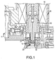
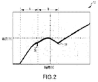
図1は、燃料蒸気制御バルブ11内に配置されたソレノイドバルブ10の一部を示す図である。図2には、バルブ10の、動作時におけるソレノイド誘導電流特性12(縦軸は電流、横軸は時間)が示されている。図1には、バルブ10が非通電状態で図示されている。バルブ10は、ソレノイドコイル14、及び、アーマチャ16を含むものであってもよい。アーマチャ16は、閉鎖位置(図1に示す位置)と開放位置との間を移動可能なものである。一実施形態において、アーマチャ16の一端部には摺動ポペット18が配置されており、このポペット18は、アーマチャ16が閉鎖位置を取るときに、バルブシート20に密着するものであってもよい。アーマチャ16とポペット18との間の空隙22によって、アーマチャ16とポペット18との間に少量の遊びまたは隙間を形成するものであってもよい。加圧条件下でもバルブ10が閉鎖状態を維持できるように、ポペット18に対して与圧ばね23を配置して、ポペット18をバルブシート20に対して付勢するものであってもよい。
FIG. 1 is a view showing a part of a
図1に示す実施形態は、常時閉型のバルブ10であり、コイル14の非励磁時には、アーマチャ16は閉鎖位置にあり、ポペット18はバルブシート20に密着している。但し、本発明の範囲を逸脱することなく他のバルブ構造を使用できることは、当業者には明らかである。
The embodiment shown in FIG. 1 is a normally closed
コイル14に電圧が印加されると、コイル14は励磁され、図2のA部に示すように、コイル14を通る電流が増大する。この期間中に、コイル14の電流は、アーマチャ16を移動させる磁力を発生するために十分な高い電流レベルに到達する。アーマチャ16は、開放位置に向かって移動し、アーマチャ16とポペット18との間の空隙22が閉じられて、アーマチャ16がポペット18の頂部に接触する。この時点で、アーマチャ16とポペット18は緊密に結合される。
When a voltage is applied to the
コイル14を通じて電流が流れ続けると、ポペット18をアーマチャ16に緊密に結合しつつ、アーマチャ16の開放位置に向かう移動が持続する。アーマチャ16の上方への移動が持続すると、ポペット18はバルブシート20から離脱する。この時点で、バルブ10に「隙間」が開く(すなわち、バルブが開き出す)。電流特性には、バルブのこのような状態変化が、第1の変曲点26として反映される。第1の変曲点26は、電流特性12の傾斜が減少したときに生じる。第1の変曲点26は、図2に示すように、僅かに現れる場合もある。但し、より高圧の用途では、第1の変曲点26は、もっと顕著に現れる場合もあり、さらに、印加された蒸気圧の大きさを検出できるほど十分に大きく現れる場合もある。
As current continues to flow through the
この第1の変曲点26は、アーマチャ16とポペット18とを緩みを持たせて結合したことの結果として生じるものである。詳しくは、このような緩みを持たせた結合によってバルブ10が開き始めたことの検出が可能となるのは、アーマチャ16が、ポペット18とは独立に移動している状態から、ポペット18とともに移動する状態に移ると、電流特性が変化するからである。典型的なソレノイドバルブでは、アーマチャとポペットとは、かしめまたは圧入によって、あるいは、場合によっては一体の構造物として形成されることによって、緊密に結合されている。このため、アーマチャとポペットとは、本質的に一斉に移動する。本発明に係る構造は、アーマチャ16とポペット18とを緩みを持たせて結合することによって、バルブ10が開き始める時点の検出を容易に実行できる電流特性を生成するものである。また、このような緩みを持たせた結合によって、ポペット18のシール動作に付加的な自由度が備えられるため、バルブ10の製造公差の累積に対する余裕も増大する。
The first inflection point 26 is a result of the loose connection between the
アーマチャ16が開放位置に向かう移動を続けると、電流は増大を続け、電流特性には、図2のB部に示すように、バルブの上昇時間及び開放応答が反映される。電流特性12のB部は、バルブ10のソレノイドコイル14を通じて流れる誘導電流の、バルブ10が開き始めた時点と完全に開放された時点との間のプロファイルに相当する。電流特性12の傾斜は、バルブ10の固有の動作特性に応じて、B部で増大する。アーマチャ16が1ストローク分を完全に移動した後、最終的な停止位置に到達してバルブ10が完全に開放されると、電流特性12には、第2の変曲点28が現れる。
As the
B部は、第1の変曲点26と第2の変曲点28によって区切られており、第1及び第2の変曲点26、28は、それぞれ、バルブ10が開き始めた時点及びバルブ10が完全に開放された時点に対応するため、B部は、アーマチャ16の閉鎖位置から開放位置への1ストローク間の正確な移動時間(すなわち、開動作の経過時間)に相当する。本発明では、先行技術とは異なり、バルブ10が開く時点に関する不確実性はない。
Part B is delimited by a first inflection point 26 and a second inflection point 28, and the first and second inflection points 26, 28 are respectively the time when the
開動作の経過時間は、多くの用途において使用可能な有益な情報である。例えば、燃料射出システムにおいて、開動作の経過時間は、特定の圧力条件下において、または、バルブの動的圧力降下を併せて考慮した場合に、バルブ10によって放出される燃料蒸気パルス質量を算出するために使用することができる。開動作の経過時間は、計量を必要とする任意の用途(例えば、燃料射出)で使用することもできる。または、開動作の経過時間を、予想される開動作の経過時間と比較して、適切なバルブ動作の診断に使用することもできる。
The elapsed time of the opening operation is useful information that can be used in many applications. For example, in a fuel injection system, the elapsed time of the opening operation calculates the fuel vapor pulse mass released by the
以上の説明では、常時閉型のバルブを例として用いたが、本発明の概念は、アーマチャの位置変化が開始するときに第1の変曲点が現れ、かつ、アーマチャがその新しい位置でハードストップに到達したときに第2の変曲点が現れるような電流特性を有する限り、本発明の範囲を逸脱することなく、他のタイプのバルブに適用することもできる。2つの変曲点の間の動作の経過時間は、所定の動作サイクルの間にアーマチャが実際に移動している時間についての有益な情報を提供するものである。 In the above description, a normally closed valve is used as an example. However, the concept of the present invention is that the first inflection point appears when the position change of the armature starts, and the armature is hard at the new position. As long as the current characteristic is such that the second inflection point appears when the stop is reached, the present invention can be applied to other types of valves without departing from the scope of the present invention. The elapsed time of motion between the two inflection points provides useful information about the time the armature is actually moving during a given motion cycle.
以上、本発明を実施するための最適な実施形態を詳細に説明したが、添付請求項の範囲内において本発明を実施するために、様々な他の設計及び実施形態が可能なことは、当業者には明らかである。 Although the best embodiment for practicing the present invention has been described in detail above, various other designs and embodiments are possible to implement the present invention within the scope of the appended claims. It is clear to the contractor.
Claims (20)
前記ソレノイドバルブのコイルを励磁し、前記アーマチャを移動させるために十分な磁力を発生させるとともに、電流の経時変化に対応する電流特性を生成する段階と、
前記電流特性中に、前記アーマチャが開放位置と閉鎖位置のうちの一方から開放位置と閉鎖位置のうちの他方に向かって移動を開始したときに発生し、前記電流特性の傾斜の減少に対応する第1の変曲点を検出する段階と、
前記電流特性中に、前記アーマチャが開放位置と閉鎖位置のうちの他方への移動を完了したときに発生する第2の変曲点を検出する段階と、を含み、
前記第1の変曲点及び前記第2の変曲点は、それぞれ前記ソレノイドバルブが開き始めた時点及び前記ソレノイドバルブが完全に開放された時点に相当し、前記第1の変曲点と前記第2の変曲点との間の時間は、閉鎖位置から開放位置への1回のストローク中の前記アーマチャの移動時間に相当する、ことを特徴とする方法。 A method of monitoring the operation of a solenoid valve having an armature movable between an open position and a closed position, and a poppet coupled to the armature and disposed on a valve seat,
Exciting a coil of the solenoid valve, generating a magnetic force sufficient to move the armature, and generating a current characteristic corresponding to a change in current over time;
Occurs when the armature starts moving from one of the open position and the closed position toward the other of the open position and the closed position during the current characteristic, corresponding to a decrease in the slope of the current characteristic Detecting a first inflection point;
The current characteristics in, look including the the steps of detecting a second inflection point that occurs when the armature has completed its movement to the other of the open and closed positions,
The first inflection point and the second inflection point correspond to a point in time when the solenoid valve starts to open and a point in time when the solenoid valve is completely opened, respectively. The time between the second inflection point corresponds to the movement time of the armature during one stroke from the closed position to the open position .
前記コイルが非励磁状態のときの閉鎖位置と前記コイルが励磁状態のときの開放位置との間を移動するアーマチャと、
前記アーマチャに直接結合されるとともに、前記アーマチャとの間に空隙が配置されているポペットと、
バルブシートと、を含むソレノイドバルブであって、
前記コイルが励磁状態のときの電流特性を有しており、該電流特性は、前記アーマチャと前記ポペットとの間の空隙によって、前記アーマチャが開放位置に向かう移動を開始して前記ポペットが前記バルブシートから上昇を開始するときに第1の変曲点を有し、
前記電流特性は、前記ソレノイドバルブの完全な開放に相当する第2の変曲点を含み、前記第1の変曲点と前記第2の変曲点との間の時間は、閉鎖位置から開放位置への1回のストローク中の前記アーマチャの移動時間に相当する、ことを特徴とするソレノイドバルブ。 Coils,
An armature that moves between a closed position when the coil is in an unexcited state and an open position when the coil is in an excited state;
A poppet that is directly coupled to the armature and in which a gap is disposed between the armature and
A solenoid valve including a valve seat,
The coil has a current characteristic when the coil is in an excited state, and the current characteristic starts to move toward the open position by the gap between the armature and the poppet so that the poppet is moved to the valve. Having a first inflection point when starting to rise from the seat,
The current characteristic includes a second inflection point corresponding to a complete opening of the solenoid valve, and a time between the first inflection point and the second inflection point is released from a closed position. A solenoid valve, which corresponds to a movement time of the armature during one stroke to a position.
ポペットと、
前記ポペットに直接結合されるとともに前記ポペットに対して移動可能であり、閉鎖位置と開放位置とを有するアーマチャと、
第1の変曲点と第2変曲点とを有し、前記第1の変曲点は、前記ポペットの、開放位置と閉鎖位置のうちの一方から離れる移動の開始に相当し、前記第2の変曲点は、前記ポペットの、開放位置と閉鎖位置のうちの他方への到達に相当する電流特性と、を含んでおり、
前記第1の変曲点と前記第2の変曲点との間の時間は、閉鎖位置から開放位置への1回のストローク中の前記ポペットの移動時間に相当する、ことを特徴とするソレノイドバルブ。 Coils,
With poppets,
An armature coupled directly to the poppet and movable with respect to the poppet and having a closed position and an open position;
A first inflection point and a second inflection point, wherein the first inflection point corresponds to the start of movement of the poppet away from one of an open position and a closed position; The inflection point of 2 includes a current characteristic corresponding to reaching the other of the open position and the closed position of the poppet,
The time between the first inflection point and the second inflection point corresponds to the movement time of the poppet during one stroke from the closed position to the open position. valve.
Applications Claiming Priority (3)
| Application Number | Priority Date | Filing Date | Title |
|---|---|---|---|
| US13/160,583 | 2011-06-15 | ||
| US13/160,583 US8823390B2 (en) | 2011-06-15 | 2011-06-15 | Solenoid-operated valve and method of monitoring same |
| PCT/IB2012/001142 WO2012172407A1 (en) | 2011-06-15 | 2012-06-13 | Solenoid-operated valve and method of monitoring same |
Publications (3)
| Publication Number | Publication Date |
|---|---|
| JP2014518360A JP2014518360A (en) | 2014-07-28 |
| JP2014518360A5 JP2014518360A5 (en) | 2015-07-30 |
| JP5917689B2 true JP5917689B2 (en) | 2016-05-18 |
Family
ID=46642579
Family Applications (1)
| Application Number | Title | Priority Date | Filing Date |
|---|---|---|---|
| JP2014515298A Active JP5917689B2 (en) | 2011-06-15 | 2012-06-13 | Solenoid valve and method for monitoring solenoid valve |
Country Status (6)
| Country | Link |
|---|---|
| US (1) | US8823390B2 (en) |
| EP (1) | EP2721331B1 (en) |
| JP (1) | JP5917689B2 (en) |
| KR (1) | KR20140034221A (en) |
| CN (2) | CN102829240B (en) |
| WO (1) | WO2012172407A1 (en) |
Families Citing this family (12)
| Publication number | Priority date | Publication date | Assignee | Title |
|---|---|---|---|---|
| US8823390B2 (en) * | 2011-06-15 | 2014-09-02 | Eaton Corporation | Solenoid-operated valve and method of monitoring same |
| DE102012218370B4 (en) * | 2012-10-09 | 2015-04-02 | Continental Automotive Gmbh | Method and device for controlling a valve |
| JP5988916B2 (en) * | 2013-05-23 | 2016-09-07 | Ckd株式会社 | Pilot type solenoid valve |
| SE538278C2 (en) * | 2013-12-13 | 2016-04-19 | Scania Cv Ab | Method and system for diagnosing a solenoid valve |
| KR20150134527A (en) | 2014-05-22 | 2015-12-02 | 주식회사 만도 | Apparatus for inspecting coil current of hydraulic valve and method for inspecting coil current thereof |
| DE102016207915B4 (en) * | 2016-05-09 | 2019-03-14 | Siemens Aktiengesellschaft | Determining the motion profile of an anchor in a magnet |
| CN106051292B (en) * | 2016-07-27 | 2018-02-09 | 河北秦汉电子科技有限公司 | A kind of electromagnetic valve work condition detection method |
| IT201800004110A1 (en) * | 2018-03-30 | 2019-09-30 | Camozzi Automation S P A | PRESSURE REGULATOR |
| DE102018217663A1 (en) | 2018-10-15 | 2020-04-16 | Continental Teves Ag & Co. Ohg | Method for determining a switching state of a valve and electromagnetic valve arrangement |
| DE102020125488A1 (en) * | 2020-01-14 | 2021-07-15 | Diehl Ako Stiftung & Co. Kg | Control circuit for an electromagnetic valve and method for monitoring a switching state of an electromagnetic valve |
| JP7424322B2 (en) * | 2021-01-19 | 2024-01-30 | Smc株式会社 | fluid pressure control device |
| CN115144683B (en) * | 2022-09-06 | 2022-11-08 | 万向钱潮股份公司 | Electromagnetic valve fault detection method and system |
Family Cites Families (19)
| Publication number | Priority date | Publication date | Assignee | Title |
|---|---|---|---|---|
| DE2121923A1 (en) | 1970-05-07 | 1971-11-25 | Orszagos Köolaj es Gazipari Tröszt Gaztechnikai Kutato es Vizsgalo Allomas, Budapest | Valve, especially for gaseous media |
| JPS62167985A (en) * | 1986-01-17 | 1987-07-24 | Taimu Giken Kk | Electromagnetic valve and detecting method for its operating condition |
| DE3807278C2 (en) | 1988-03-05 | 1996-05-23 | Tech Ueberwachungs Verein Rhei | Process for safety-related checking of solenoid valves and measuring arrangement for carrying out the process |
| JPH03293567A (en) * | 1990-04-12 | 1991-12-25 | Nippon Steel Corp | Apparatus for diagnosing operation of movable part operated by electromagnetic force |
| DE4013393A1 (en) | 1990-04-26 | 1991-10-31 | Lucas Ind Plc | Electromagnetic valve function monitoring method - measuring coil voltage and/or current fluctuations after applying actuating current |
| US5492009A (en) | 1991-03-11 | 1996-02-20 | Siemens Aktiengesellschaft | Method and apparatus for testing a valve actuated by an electromagnet having an armature |
| DE4107813A1 (en) * | 1991-03-11 | 1992-09-17 | Siemens Ag | METHOD AND DEVICE FOR TESTING A FITTING |
| JPH0552445U (en) * | 1991-12-16 | 1993-07-13 | 株式会社ミクニアデック | Solenoid valve structure |
| US6326898B1 (en) | 2000-10-24 | 2001-12-04 | Xerox Corporation | Solenoid plunger position detection algorithm |
| JP2003194671A (en) * | 2002-09-27 | 2003-07-09 | Japan Atom Power Co Ltd:The | Function diagnostic method of valve device |
| US7051993B2 (en) * | 2004-03-10 | 2006-05-30 | Eaton Corporation | Solenoid operated valve and method of making same |
| US7595971B2 (en) | 2005-06-15 | 2009-09-29 | Honeywell International Inc. | Sensing armature motion in high-speed solenoids |
| CN101663523B (en) * | 2007-01-22 | 2011-09-21 | Imi韦伯有限公司 | Solenoid valve having a two piece moving valve element |
| GB2453947A (en) | 2007-10-23 | 2009-04-29 | Vetco Gray Controls Ltd | Solenoid coil current used in armature movement monitoring |
| DE102008011573B4 (en) | 2008-02-28 | 2013-02-14 | Danfoss A/S | Electromagnetic actuator and valve |
| US8542006B2 (en) * | 2008-12-16 | 2013-09-24 | Hydril USA Manfacturing LLC | Movement detection circuit of solenoid shear seal valve on subsea pressure control system and method of detecting movement of solenoid actuator |
| DE102010024585A1 (en) * | 2009-06-26 | 2010-12-30 | Magna Powertrain Ag & Co Kg | magnetic valve |
| JP5422459B2 (en) * | 2010-03-26 | 2014-02-19 | 富士フイルム株式会社 | Apparatus and method for confirming operation of latch-type electromagnetic valve, and ink jet recording apparatus |
| US8823390B2 (en) * | 2011-06-15 | 2014-09-02 | Eaton Corporation | Solenoid-operated valve and method of monitoring same |
-
2011
- 2011-06-15 US US13/160,583 patent/US8823390B2/en active Active
-
2012
- 2012-06-13 KR KR1020137033134A patent/KR20140034221A/en not_active Application Discontinuation
- 2012-06-13 WO PCT/IB2012/001142 patent/WO2012172407A1/en active Application Filing
- 2012-06-13 JP JP2014515298A patent/JP5917689B2/en active Active
- 2012-06-13 EP EP12745898.2A patent/EP2721331B1/en not_active Not-in-force
- 2012-06-15 CN CN201210264158.0A patent/CN102829240B/en not_active Expired - Fee Related
- 2012-06-15 CN CN2012203668849U patent/CN202790812U/en not_active Expired - Fee Related
Also Published As
| Publication number | Publication date |
|---|---|
| CN102829240B (en) | 2017-03-01 |
| CN202790812U (en) | 2013-03-13 |
| EP2721331A1 (en) | 2014-04-23 |
| WO2012172407A1 (en) | 2012-12-20 |
| US8823390B2 (en) | 2014-09-02 |
| US20120319700A1 (en) | 2012-12-20 |
| JP2014518360A (en) | 2014-07-28 |
| EP2721331B1 (en) | 2017-11-01 |
| KR20140034221A (en) | 2014-03-19 |
| CN102829240A (en) | 2012-12-19 |
Similar Documents
| Publication | Publication Date | Title |
|---|---|---|
| JP5917689B2 (en) | Solenoid valve and method for monitoring solenoid valve | |
| JP6520814B2 (en) | Fuel injection control device | |
| WO2015118854A1 (en) | Fuel injection control device | |
| WO2017191729A1 (en) | Fuel injection control device | |
| CN109328265B (en) | Fuel injection control device | |
| JP5534496B2 (en) | Control device for solenoid valve | |
| WO2015075887A1 (en) | Fuel injection control device and fuel injection system | |
| US9664159B2 (en) | Parameter estimation in an actuator | |
| KR101863903B1 (en) | Method and apparatus for operating an injection valve | |
| JP6512167B2 (en) | Fuel injection control device | |
| WO2017191733A1 (en) | Fuel injection control device | |
| JP2014518360A5 (en) | ||
| KR20150018519A (en) | Method for monitoring an injection valve | |
| JP2017201158A (en) | Fuel injection control device | |
| JP6038300B2 (en) | Valve operating method, open loop / closed loop control device for controlling valve operation, and computer program for open loop / closed loop control device | |
| WO2015039821A1 (en) | Fluid injection valve | |
| US10914263B2 (en) | Determination of a point in time of a predetermined state of a fuel injector | |
| JP2017089890A (en) | Solenoid valve control system | |
| WO2017090320A1 (en) | Fuel injection control device and fule injection system | |
| JP2014519298A (en) | Piezo actuator operating method and operating device | |
| JP2007085318A (en) | Control device of electromagnetic-drive valve | |
| JP2004157775A (en) | Solenoid actuator | |
| US20120205461A1 (en) | Compensation for spool motion related fuel delivery drift over time in a hydraulically actuated fuel injector |
Legal Events
| Date | Code | Title | Description |
|---|---|---|---|
| A521 | Request for written amendment filed |
Free format text: JAPANESE INTERMEDIATE CODE: A523 Effective date: 20150612 |
|
| A621 | Written request for application examination |
Free format text: JAPANESE INTERMEDIATE CODE: A621 Effective date: 20150612 |
|
| A871 | Explanation of circumstances concerning accelerated examination |
Free format text: JAPANESE INTERMEDIATE CODE: A871 Effective date: 20150612 |
|
| A975 | Report on accelerated examination |
Free format text: JAPANESE INTERMEDIATE CODE: A971005 Effective date: 20150730 |
|
| A131 | Notification of reasons for refusal |
Free format text: JAPANESE INTERMEDIATE CODE: A131 Effective date: 20150916 |
|
| A521 | Request for written amendment filed |
Free format text: JAPANESE INTERMEDIATE CODE: A523 Effective date: 20151209 |
|
| TRDD | Decision of grant or rejection written | ||
| A01 | Written decision to grant a patent or to grant a registration (utility model) |
Free format text: JAPANESE INTERMEDIATE CODE: A01 Effective date: 20160309 |
|
| A61 | First payment of annual fees (during grant procedure) |
Free format text: JAPANESE INTERMEDIATE CODE: A61 Effective date: 20160406 |
|
| R150 | Certificate of patent or registration of utility model |
Ref document number: 5917689 Country of ref document: JP Free format text: JAPANESE INTERMEDIATE CODE: R150 |
|
| R250 | Receipt of annual fees |
Free format text: JAPANESE INTERMEDIATE CODE: R250 |
|
| R250 | Receipt of annual fees |
Free format text: JAPANESE INTERMEDIATE CODE: R250 |
|
| S111 | Request for change of ownership or part of ownership |
Free format text: JAPANESE INTERMEDIATE CODE: R313113 |
|
| S531 | Written request for registration of change of domicile |
Free format text: JAPANESE INTERMEDIATE CODE: R313531 |
|
| R350 | Written notification of registration of transfer |
Free format text: JAPANESE INTERMEDIATE CODE: R350 |
|
| R371 | Transfer withdrawn |
Free format text: JAPANESE INTERMEDIATE CODE: R371 |
|
| S111 | Request for change of ownership or part of ownership |
Free format text: JAPANESE INTERMEDIATE CODE: R313113 |
|
| R350 | Written notification of registration of transfer |
Free format text: JAPANESE INTERMEDIATE CODE: R350 |