JP5915914B2 - Drainage pump for washing machine and washing machine - Google Patents
Drainage pump for washing machine and washing machine Download PDFInfo
- Publication number
- JP5915914B2 JP5915914B2 JP2014540290A JP2014540290A JP5915914B2 JP 5915914 B2 JP5915914 B2 JP 5915914B2 JP 2014540290 A JP2014540290 A JP 2014540290A JP 2014540290 A JP2014540290 A JP 2014540290A JP 5915914 B2 JP5915914 B2 JP 5915914B2
- Authority
- JP
- Japan
- Prior art keywords
- washing machine
- drainage
- filter
- impeller
- front space
- Prior art date
- Legal status (The legal status is an assumption and is not a legal conclusion. Google has not performed a legal analysis and makes no representation as to the accuracy of the status listed.)
- Expired - Fee Related
Links
- 238000005406 washing Methods 0.000 title claims description 49
- XLYOFNOQVPJJNP-UHFFFAOYSA-N water Substances O XLYOFNOQVPJJNP-UHFFFAOYSA-N 0.000 claims description 47
- 230000006837 decompression Effects 0.000 claims description 25
- 238000001914 filtration Methods 0.000 claims description 23
- 238000000034 method Methods 0.000 description 5
- 230000018044 dehydration Effects 0.000 description 4
- 238000006297 dehydration reaction Methods 0.000 description 4
- 230000008569 process Effects 0.000 description 4
- 230000009471 action Effects 0.000 description 3
- 230000000903 blocking effect Effects 0.000 description 2
- 230000004048 modification Effects 0.000 description 2
- 238000012986 modification Methods 0.000 description 2
- 238000010586 diagram Methods 0.000 description 1
- 230000000694 effects Effects 0.000 description 1
- 230000005484 gravity Effects 0.000 description 1
- 230000006872 improvement Effects 0.000 description 1
- 230000009467 reduction Effects 0.000 description 1
- 230000000630 rising effect Effects 0.000 description 1
- 238000003756 stirring Methods 0.000 description 1
Images


Classifications
-
- D—TEXTILES; PAPER
- D06—TREATMENT OF TEXTILES OR THE LIKE; LAUNDERING; FLEXIBLE MATERIALS NOT OTHERWISE PROVIDED FOR
- D06F—LAUNDERING, DRYING, IRONING, PRESSING OR FOLDING TEXTILE ARTICLES
- D06F39/00—Details of washing machines not specific to a single type of machines covered by groups D06F9/00 - D06F27/00
- D06F39/08—Liquid supply or discharge arrangements
- D06F39/083—Liquid discharge or recirculation arrangements
- D06F39/085—Arrangements or adaptations of pumps
-
- D—TEXTILES; PAPER
- D06—TREATMENT OF TEXTILES OR THE LIKE; LAUNDERING; FLEXIBLE MATERIALS NOT OTHERWISE PROVIDED FOR
- D06F—LAUNDERING, DRYING, IRONING, PRESSING OR FOLDING TEXTILE ARTICLES
- D06F39/00—Details of washing machines not specific to a single type of machines covered by groups D06F9/00 - D06F27/00
- D06F39/10—Filtering arrangements
-
- F—MECHANICAL ENGINEERING; LIGHTING; HEATING; WEAPONS; BLASTING
- F04—POSITIVE - DISPLACEMENT MACHINES FOR LIQUIDS; PUMPS FOR LIQUIDS OR ELASTIC FLUIDS
- F04D—NON-POSITIVE-DISPLACEMENT PUMPS
- F04D19/00—Axial-flow pumps
- F04D19/02—Multi-stage pumps
-
- F—MECHANICAL ENGINEERING; LIGHTING; HEATING; WEAPONS; BLASTING
- F04—POSITIVE - DISPLACEMENT MACHINES FOR LIQUIDS; PUMPS FOR LIQUIDS OR ELASTIC FLUIDS
- F04D—NON-POSITIVE-DISPLACEMENT PUMPS
- F04D29/00—Details, component parts, or accessories
- F04D29/08—Sealings
- F04D29/16—Sealings between pressure and suction sides
- F04D29/165—Sealings between pressure and suction sides especially adapted for liquid pumps
- F04D29/167—Sealings between pressure and suction sides especially adapted for liquid pumps of a centrifugal flow wheel
-
- F—MECHANICAL ENGINEERING; LIGHTING; HEATING; WEAPONS; BLASTING
- F04—POSITIVE - DISPLACEMENT MACHINES FOR LIQUIDS; PUMPS FOR LIQUIDS OR ELASTIC FLUIDS
- F04D—NON-POSITIVE-DISPLACEMENT PUMPS
- F04D29/00—Details, component parts, or accessories
- F04D29/40—Casings; Connections of working fluid
- F04D29/42—Casings; Connections of working fluid for radial or helico-centrifugal pumps
- F04D29/426—Casings; Connections of working fluid for radial or helico-centrifugal pumps especially adapted for liquid pumps
-
- F—MECHANICAL ENGINEERING; LIGHTING; HEATING; WEAPONS; BLASTING
- F04—POSITIVE - DISPLACEMENT MACHINES FOR LIQUIDS; PUMPS FOR LIQUIDS OR ELASTIC FLUIDS
- F04D—NON-POSITIVE-DISPLACEMENT PUMPS
- F04D29/00—Details, component parts, or accessories
- F04D29/66—Combating cavitation, whirls, noise, vibration or the like; Balancing
- F04D29/669—Combating cavitation, whirls, noise, vibration or the like; Balancing especially adapted for liquid pumps
Landscapes
- Engineering & Computer Science (AREA)
- Mechanical Engineering (AREA)
- General Engineering & Computer Science (AREA)
- Textile Engineering (AREA)
- Detail Structures Of Washing Machines And Dryers (AREA)
- Main Body Construction Of Washing Machines And Laundry Dryers (AREA)
- Control Of Washing Machine And Dryer (AREA)
Description
本発明は、洗濯機、特に排水ポンプを採用した洗濯機および洗濯機用低騒音排水ポンプに関するものである。 The present invention relates to a washing machine, particularly a washing machine employing a drain pump and a low noise drain pump for the washing machine.
家庭用電気洗濯機は、パルセーター式洗濯機、ドラム式洗濯機、攪拌式洗濯機に分けられる。ドラム式洗濯機は最初、ヨーロッパで登場したが、消費水準の上昇や消費者ニーズの変化に伴い、ドラム式洗濯機はアジアでも広く普及するようになった。同時に生活環境の改善や、洗濯機ユーザーの家庭生活の質の向上によって、静かな住環境がますます重要視されるようになる。そのため、家電の騒音も各家電メーカーが解決しようとする重要な課題の一つになっている。そのうち、洗濯機の低騒音化が進んできた。 Household electric washing machines are classified into pulsator-type washing machines, drum-type washing machines, and stirring-type washing machines. Drum-type washing machines first appeared in Europe, but due to rising consumption levels and changing consumer needs, drum-type washing machines have become widespread in Asia. At the same time, the quiet living environment is becoming more and more important due to the improvement of living environment and the quality of home life of washing machine users. Therefore, the noise of home appliances is one of the important issues that each home appliance manufacturer tries to solve. Over time, the noise of washing machines has been reduced.
ドラム式洗濯機は、全てポンプによる強制排水方式を採用し、ドラム内の水を排水ポンプと排水ホースを通して機外へ排出される仕組みになっている。そのため、脱水時、排水ポンプが排水ホース内の水流に接触して、ブウブウと音を立てる騒音問題は徹底的に解決できていないのが現状である。ドラム式洗濯機内の水を完全に排出した後でも、排水ポンプは約1.2mの揚程があるため、この部分のホース内に溜まった水は排出できず、逆に重力作用で、絶えず下に向かって排水ポンプのインペラに激しくぶつかり、更にインペラに投げ出されるので、ブウブウと音を立てる。既存の低価格帯の洗濯機では、水位スイッチを採用しており、排水ポンプは脱水工程において稼動し続けなければならない。高級洗濯機でも、水位センサーを採用して、低水位の時、最低水位を検出すると、排水ポンプの稼動を止めることができるが、センサーの信号は外部干渉の影響を受けると、精度が低下し、判断ミスが極めて発生しやすい。その結果、騒音があったり、完全に排水できなかったりして、ユーザーの低騒音というニーズに応えることができない。 All drum-type washing machines adopt a forced drainage system using a pump, and the water in the drum is drained out of the machine through a drainage pump and a drainage hose. For this reason, at the time of dehydration, the current problem is that the drainage pump makes contact with the water flow in the drainage hose and makes a noise. Even after the water in the drum-type washing machine has been completely drained, the drainage pump has a lift of about 1.2m, so the water accumulated in this part of the hose cannot be drained. As it hits the impeller of the drainage pump violently, it is thrown into the impeller and makes a loud noise. Existing low-priced washing machines employ a water level switch, and the drain pump must continue to operate during the dewatering process. Even in a high-grade washing machine, if the water level sensor is used and the minimum water level is detected when the water level is low, the operation of the drainage pump can be stopped. , Judgment mistakes are extremely likely to occur. As a result, there is noise, or drainage is not possible, and the user's need for low noise cannot be met.
出願番号がCN200920230820.4の中国特許で、洗濯機用排水ポンプの低騒音ポンプケーシングが提案されている。それは、主にポンプケーシングの排水口に近い内部空間とろ過空間との間にあるポンプ内壁の端面に、防爆孔を設けることを含む。ただし、この防爆孔が排水管口より低いので、ポンプの内部空間内において依然、水と空気が混ざったものができるので、排水管内にある水が逆流する時インペラにぶつかることによって発生する騒音問題を完全に解決することができない。 A Chinese patent with an application number of CN200920230820.4 proposes a low noise pump casing for a washing machine drainage pump. It includes providing an explosion-proof hole on the end face of the inner wall of the pump, which is mainly between the internal space near the drain outlet of the pump casing and the filtration space. However, since this explosion-proof hole is lower than the drain pipe opening, water and air can still be mixed in the internal space of the pump, so noise problems caused by impinging on the impeller when water in the drain pipe flows backward Cannot be solved completely.
本発明は上述した事情に鑑みてなされたものである。 The present invention has been made in view of the above-described circumstances.
本発明は、従来の課題を解決して、騒音を低減できる洗濯機用排水ポンプを提供することを目的とする。 An object of this invention is to provide the drainage pump for washing machines which solves the conventional subject and can reduce noise.
本発明は、更に当該排水ポンプを有する洗濯機を提供することを目的とする。 Another object of the present invention is to provide a washing machine having the drain pump.
本発明は上述した課題を解決するために、排水用モーターとポンプケーシングとインペラとフィルタとからなる洗濯機用排水ポンプにおいて、前記ポンプケーシングに給水管口、排水管口を設け、ポンプケーシング内部に給排水の順に連通した前部空間と後部空間と有し、後部空間内に前記インペラを設け、排水用モーターの回転軸と同軸上に配設し、前部空間内に前記フィルタを設け、前記フィルタのろ過出口がインペラに対応する側に、減圧孔付減圧板を一体的に設けたものである。 In order to solve the above-described problems, the present invention provides a washing machine drainage pump including a drainage motor, a pump casing, an impeller, and a filter. The pump casing is provided with a water supply pipe port and a drainage pipe port, and the pump casing is provided inside the pump casing. A front space and a rear space communicating in the order of water supply and drainage; the impeller is provided in the rear space; the rotation shaft of the motor for drainage is disposed coaxially; the filter is provided in the front space; The pressure reducing plate with a pressure reducing hole is integrally provided on the side corresponding to the impeller.
前記排水管口をインペラの径方向に沿って後部空間のポンプケーシング上に設け、給水管口を前部空間の軸方向に前部空間のポンプケーシング上に設ける。 The drain pipe port is provided on the pump casing in the rear space along the radial direction of the impeller, and the water supply pipe port is provided on the pump casing in the front space in the axial direction of the front space.
前記前部空間の一端が後部空間と連通し、他端に開口部をつくり、フィルタは、この開口部を通して前部空間に配設し、前記開口部に開閉蓋を設ける。 One end of the front space communicates with the rear space, and an opening is formed at the other end. The filter is disposed in the front space through the opening, and an opening / closing lid is provided in the opening.
前記開閉蓋とフィルタとが一体的な構造で、かつ、相対回転自在であり、開閉蓋は、ねじ山を介して、前部空間にねじ結合する。 The opening / closing lid and the filter have an integral structure and are relatively rotatable, and the opening / closing lid is screwed to the front space via a screw thread.
前記フィルタが円柱形構造で、一端が支持板、他端が前記ろ過出口であり、支持板とろ過出口の間は、支持シートを介して接続し、ろ過出口は中空円筒構造で、この中空円筒がインペラに相対する一端に同軸上に前記減圧板を一体的に設ける。 The filter has a cylindrical structure, one end is a support plate, the other end is the filtration outlet, the support plate and the filtration outlet are connected via a support sheet, and the filtration outlet has a hollow cylindrical structure. Is integrally provided with the decompression plate coaxially at one end facing the impeller.
前記減圧板は、輪状構造で、輪の内径とろ過出口の内径とが同じく、前記インペラの外形より小さくて、輪の上に減圧孔を均等な間隔で設ける。 The decompression plate has an annular structure, and the inner diameter of the ring and the inner diameter of the filtration outlet are the same as those of the impeller, and decompression holes are provided on the ring at equal intervals.
前記ろ過出口の外径が支持板の直径より小さく、支持シートがL字型構造で、中空円筒の長さは、支持板と減圧板の間の距離より小さい。中空円筒の長さが給水管口の給水経路を完全に遮らないことが好ましい。 The outer diameter of the filtration outlet is smaller than the diameter of the support plate, the support sheet has an L-shaped structure, and the length of the hollow cylinder is smaller than the distance between the support plate and the decompression plate. It is preferable that the length of the hollow cylinder does not completely block the water supply path of the water supply pipe port.
前記支持シートが前部空間の内壁に対応する側に、固定用突出部を設け、前部空間の内壁に、開口部から前部空間の軸方向に沿って固定用突出部に対応する固定用溝を設け、この固定用溝と給水管口とが同一軸方向線上にない。 A fixing protrusion is provided on the side of the support sheet corresponding to the inner wall of the front space, and the fixing sheet corresponds to the fixing protrusion along the axial direction of the front space on the inner wall of the front space from the opening. A groove is provided, and the fixing groove and the water supply pipe port are not on the same axial line.
前記支持シートが2〜4組であるが、2組が好ましい。 Although the said support sheet is 2-4 sets, 2 sets are preferable.
前記前部空間と後部空間との間に減圧板を支持するための環状突起部を設け、前記減圧板の最大直径が環状突起部の内径より大きく、インペラの外径が環状突起部の内径に合うようにする。 An annular projection for supporting a decompression plate is provided between the front space and the rear space, the maximum diameter of the decompression plate is larger than the inner diameter of the annular projection, and the outer diameter of the impeller is equal to the inner diameter of the annular projection. To fit.
前記減圧孔の形状は、円形、楕円形、四角形または棒状をした貫通孔のうちの少なくとも一種類で、前記減圧孔の総面積が排水管口の断面積の0.2〜1倍になるようにする。 The shape of the decompression hole is at least one of a circular, elliptical, quadrangular or rod-shaped through hole, and the total area of the decompression hole is 0.2 to 1 times the cross-sectional area of the drainage pipe port. To.
本発明にかかる洗濯機は、給水手段と、排水ポンプを有する排水手段とを備え、排水ポンプは、排水用モーターとポンプケーシングとインペラとフィルタとからなり、ポンプケーシングに給水管口、排水管口を設け、ポンプケーシング内部に給排水の順に連通した前部空間と後部空間と有し、後部空間内に前記インペラを設け、排水用モーターの回転軸と同軸上に配設し、前部空間内に前記フィルタを設け、前記フィルタのろ過出口がインペラに対応する側に、減圧孔付減圧板を一体的に設けたものである。 The washing machine according to the present invention includes a water supply means and a drainage means having a drainage pump, and the drainage pump includes a drainage motor, a pump casing, an impeller, and a filter. The pump casing has a front space and a rear space that communicate with each other in the order of water supply and drainage, the impeller is provided in the rear space, and is disposed coaxially with the rotation shaft of the motor for drainage. The filter is provided, and a pressure reducing plate with a pressure reducing hole is integrally provided on the side where the filter outlet of the filter corresponds to the impeller.
本発明かかる発明によれば、ポンプケーシング内部に給排水の順に連通した前部空間と後部空間と有し、排水ポンプのフィルタのろ過出口がインペラに対応する側に、減圧孔付減圧板を一体的に設けたから、排水時、排水ポンプにより水を完全に排出した後でも、次の脱水工程において衣類に含まれた水が絶えず投げ出されてくるため、排水ポンプは稼動を続ける。この時、排水管において逆流する水は、重力作用で大きな衝撃力をもってポンプの内部空間内の空気に衝撃を与えても、ポンプの内部空間内の空気が減圧孔を通して排出されるので、洗濯機の脱水時に大きな騒音が出ないようにすることができる。本発明は、構造が簡単で、信頼性が高く、低コストや騒音低減の効果を実現することができる。また、故障率が低いので、洗濯過程における騒音問題を解決し、ヒューマニズムを実現することができる。 According to the invention of the present invention, the pump casing has a front space and a rear space that are communicated in the order of water supply and drainage, and the filtration outlet of the filter of the drainage pump is integrally formed on the side corresponding to the impeller. Since the water contained in the clothing is continuously thrown out in the next dehydration process even after the water is completely discharged by the drain pump, the drain pump continues to operate. At this time, even if the water flowing backward in the drain pipe impacts the air in the internal space of the pump with a large impact force due to the gravity action, the air in the internal space of the pump is discharged through the decompression hole. It is possible to prevent a loud noise during dehydration. The present invention has a simple structure, is highly reliable, and can realize an effect of low cost and noise reduction. Moreover, since the failure rate is low, it is possible to solve the noise problem in the washing process and realize humanism.
以下、本発明の一実施例について、図面を参照しながら説明する。 Hereinafter, an embodiment of the present invention will be described with reference to the drawings.
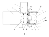
本発明にかかる洗濯機は、給水手段と、排水ポンプを有する排水手段とを備える。図1に示すように、洗濯機用排水ポンプはポンプケーシング1を有し、ポンプケーシング1内部に給排水の順に連通した前部空間92と後部空間91と、即ち図中に示す右室と左室とを有し、前部空間92と後部空間91との間に環状突起部を設けている。
The washing machine according to the present invention includes water supply means and drainage means having a drainage pump. As shown in FIG. 1, the drainage pump for a washing machine has a pump casing 1, and a
後部空間91内に前記インペラ4を設け、排水用モーター5の回転軸と同軸上に配設し、前部空間92内にフィルタ8を設け、前記排水管口6をインペラ4の径方向に沿って後部空間91のポンプケーシング上に設け、給水管口2を前部空間92の軸方向に前部空間のポンプケーシング上に設け、前部空間92の一端が後部空間91と連通し、他端に開口部9をつくり、フィルタ8は、この開口部を通して前部空間92に配設し、前記開口部9に開閉蓋83を設けている。
The impeller 4 is provided in the
この開閉蓋83は、開口部9に取り付けられた着脱可能なもの、または、開閉蓋83とフィルタ8とを一体的な構造とし、開閉蓋83とフィルタ8とが相対回転自在で、開閉蓋83は、ねじ山を介して、前部空間92の開口部9にねじ結合し、または、ボルトおよびその他の取り外し可能な結合方法としている。
The opening /
本発明にかかるフィルタ8が円柱形構造で、一端が支持板84、他端が前記ろ過出口82であり、支持板84とろ過出口82との間は、支持シート81を介して接続し、ろ過出口82は中空円筒構造で、この中空円筒がインペラ4に相対する一端に同軸上に減圧板3を一体的に設けている。開閉蓋83がフィルタ8に連結した場合、開閉蓋83と支持板84は軸方向において相対回転自在に連結するようにしている。
The
前記減圧板3は、輪状構造で、輪の内径とろ過出口82の内径とが同じく、インペラ4の外径より小さくて、輪の上に減圧孔31を均等な間隔で設けている。また、減圧孔31の形状は、円形、楕円形、四角形または棒状をした貫通孔のうちの少なくとも一種類で、前記減圧孔31の総面積が排水管口6の断面積の0.2〜1倍になるようにしている。
The
前記ろ過出口82の外径が支持板84の直径より小さく、支持シート81がL字型構造で、中空円筒、即ちろ過出口82の長さは、支持板81と減圧板3との間の距離より小さい。ろ過出口82の長さが給水管口2の給水経路を完全に遮らないことが好ましい。
The outer diameter of the
本発明は、フィルタ8が前部空間92において回転することにより排水効率に影響を与えることを防止するために、前記支持シート81が前部空間92の内壁に対応する側に、固定用突出部7を設け、前部空間92の内壁に、開口部9から前部空間の軸方向に沿って固定用突出部7に対応する固定用溝を設け(図中に示されていない)。また、支持シート81が給水管口2の給水経路を遮ることを防止するために、この固定用溝と給水管口とが同一軸方向線上にないようにしている。前記支持シート81が2〜4組であるが、2組が好ましい。
In the present invention, in order to prevent the
洗濯機が水を排水する時、洗濯槽内の洗濯水はポンプケーシング上の給水管口2から入って、前部空間92、後部空間91に充満し、インペラ4の作用で排水管口6から排水管を通して洗濯機外へと排出される。洗濯水が前部空間92から後部空間91に入る時、ろ過出口82を通して、硬貨や異物をろ過出口外部の前部空間92に止めることにより、後部空間91に入ってインペラ4を壊すことを防止することができる。槽内の洗濯水が完全排出に近い時になると、給水管口2から前部空間92に入る水が少なくなる。この時、排水管口6と洗濯機排水管(図中に示されていない)内の水は、重力作用で逆流し、高速度で後部空間91に衝撃を与える。そして、後部空間91内の空気は、インペラの回転による遠心力の作用で一定の圧力を持つが、後部空間91内の圧力は減圧板3上の減圧孔31を介して、短時間に前部空間92に入ることができる。また、前部空間92、給水管口2が洗濯槽と連通しているため、後部空間の中の空気は減圧孔31を介して、圧力を滞りなく前部空間およびそれと連通した外槽に排出することにより、「ドーン、ドーン」という騒音を低減することができる。
When the washing machine drains water, the washing water in the washing tub enters from the water supply pipe port 2 on the pump casing, fills the
本発明の最も良い実施例では、図2に示すように、減圧孔31を圧力のかかった後部空間の部位に設けることにより、排水管口6から水が逆流する時でも、後部空間91において大きな抵抗力が生じないことを確保すると共に、圧力を前部空間92およびそれと連通した外槽に圧力を逃がすことができる。
In the best embodiment of the present invention, as shown in FIG. 2, by providing the
フィルタ8がちょうど後部空間91をふさいだ側に密閉空間を形成させるために、インペラの外径Cと環状突起部93の内径Bとが合うようにしている。「合う」とは、インペラの外径が環状突起部の内径に等しく、または、環状突起部の内径よりやや大きく、または、小さいこと、フィルタ8のろ過出口82の内径がインペラの外径Cより小さいことを指す。ろ過出口82の内径が大きすぎる場合、後部空間91において圧力を形成する空間がないため、排水ポンプが排水しにくくなる。前記減圧板3の外径が環状突起部93の内径Bより大きいようにし、環状突起部93を介して、フィルタの移動を防止することができる。
The outer diameter C of the impeller and the inner diameter B of the annular projecting
以上のように上述した発明によれば、洗濯機用排水ポンプにおいて、ポンプケーシングとフィルタの右端の蓋とが密閉した内部空間を構成し、フィルタの左端の端面に気体を排除できる減圧孔を設け、ほかの部品を要しないから、構造が簡単で、信頼性が高く、故障率が低く、いかなるコストをも増やさない。また、排水工程において、ポンプケーシング内の水と空気が混ざった物が、ポンプケーシングとろ過空間の間を流れることを確保できるため、洗濯機の脱水工程における騒音を効果的に低減することができる。 As described above, according to the invention described above, in the drain pump for a washing machine, the pump casing and the right end lid of the filter constitute a sealed internal space, and the pressure reducing hole capable of excluding gas is provided in the end surface of the left end of the filter. Since no other parts are required, the structure is simple, the reliability is high, the failure rate is low, and no cost is increased. Further, in the draining process, it is possible to ensure that water and air mixed in the pump casing flows between the pump casing and the filtration space, so that noise in the dehydration process of the washing machine can be effectively reduced. .
当然ながら、本発明は上記の実施例に限らない。この分野の技術者にとって容易に分かる解決手段で、本発明の主旨または範囲を逸脱しない状況の下、本発明に修正、変更を加えることは、本発明の特許請求の範囲およびその取替えとみなされる範囲にある。本発明はドラム式洗濯機に適用するのみでなく、排水ポンプによる強制排水方式を用いるパルセーター式洗濯機、攪拌式洗濯機にも適用するので、本発明はこのような修正と変更を含むものである。 Of course, the present invention is not limited to the above embodiments. Modifications and changes made to the present invention under circumstances that do not depart from the spirit or scope of the present invention are solutions that can be easily understood by those skilled in the art, and are regarded as claims of the present invention and replacement thereof. Is in range. Since the present invention is applied not only to a drum type washing machine but also to a pulsator type washing machine and a stirring type washing machine using a forced drainage system using a drainage pump, the present invention includes such modifications and changes. .
1 ポンプケーシング
2 給水管口
3 減圧板
31 減圧孔
4 インペラ
5 排水用モーター
6 排水管口
7 固定用突出部
8 フィルタ
81 支持シート
82 ろ過出口
83 開閉蓋
84 支持板
9 開口部
91 後部空間
92 前部空間
93 環状突起部
DESCRIPTION OF SYMBOLS 1 Pump casing 2 Water
Claims (10)
前記ポンプケーシングに給水管口、排水管口が設けられ、
前記ポンプケーシング内部に給排水の順に連通した前部空間と後部空間と有し、
前記後部空間内に前記インペラが設けられ、前記インペラは前記排水用モーターの回転軸と同軸上に配設され、
前記前部空間内に前記フィルタが設けられ、
前記フィルタの、前記インペラに隣接するろ過出口に、減圧孔付減圧板が前記フィルタと一体的に設けられ、
前記減圧板は輪状構造で、輪の内径は、前記ろ過出口の内径と同じで前記インペラの外径より小さく、輪の上に減圧孔が均等な間隔で設けられ、
少なくとも一つの前記減圧孔は前記ろ過出口の上側に位置し、
前記減圧孔の形状は、円形、楕円形、四角形または棒状をした貫通孔のうちの少なくとも一種類で、前記減圧孔の総面積が前記排水管口の断面積の0.2〜1倍であることを特徴とする洗濯機用排水ポンプ。 A drainage pump for a washing machine composed of a drainage motor, a pump casing, an impeller, and a filter, wherein the pump casing is provided with a water supply pipe port and a drain pipe port ,
Has a front space and a rear space communicating with the order of water supply and drainage inside the pump casing,
Wherein the impeller in the rear space is provided, wherein the impeller is arranged coaxially with the rotation axis of the drainage motor,
The filter is provided in the front space ;
At the filtration outlet of the filter adjacent to the impeller, a decompression plate with a decompression hole is provided integrally with the filter ,
The pressure reducing plate has a ring-shaped structure, and the inner diameter of the ring is the same as the inner diameter of the filtration outlet and is smaller than the outer diameter of the impeller, and the pressure reducing holes are provided at equal intervals on the ring,
At least one of the vacuum holes is located above the filtration outlet;
The shape of the decompression hole is at least one of a circular, elliptical, quadrangular or rod-like through hole, and the total area of the decompression hole is 0.2 to 1 times the cross-sectional area of the drain pipe port. A drainage pump for a washing machine characterized by that .
Applications Claiming Priority (3)
| Application Number | Priority Date | Filing Date | Title |
|---|---|---|---|
| CN201110349833.5 | 2011-11-08 | ||
| CN2011103498335A CN102505426A (en) | 2011-11-08 | 2011-11-08 | Drainage pump of washing machine, and washing machine using same |
| PCT/CN2011/084821 WO2013067739A1 (en) | 2011-11-08 | 2011-12-28 | Drainage pump device for washing machine and washing machine therewith |
Publications (2)
| Publication Number | Publication Date |
|---|---|
| JP2014532530A JP2014532530A (en) | 2014-12-08 |
| JP5915914B2 true JP5915914B2 (en) | 2016-05-11 |
Family
ID=46217555
Family Applications (1)
| Application Number | Title | Priority Date | Filing Date |
|---|---|---|---|
| JP2014540290A Expired - Fee Related JP5915914B2 (en) | 2011-11-08 | 2011-12-28 | Drainage pump for washing machine and washing machine |
Country Status (6)
| Country | Link |
|---|---|
| US (1) | US9683572B2 (en) |
| EP (1) | EP2778272B1 (en) |
| JP (1) | JP5915914B2 (en) |
| KR (1) | KR101748473B1 (en) |
| CN (1) | CN102505426A (en) |
| WO (1) | WO2013067739A1 (en) |
Families Citing this family (12)
| Publication number | Priority date | Publication date | Assignee | Title |
|---|---|---|---|---|
| CN203248412U (en) * | 2013-02-26 | 2013-10-23 | 无锡小天鹅股份有限公司 | Draining pump and washing machine including same |
| CN104980066B (en) * | 2014-04-11 | 2018-01-05 | 常州雷利电机科技有限公司 | Draining pump DC Brushless Motor system and its control method and control device |
| CN105088702B (en) * | 2014-04-16 | 2018-12-18 | 无锡小天鹅股份有限公司 | Washing machine and its draining pump filter device |
| US9840803B2 (en) * | 2015-10-20 | 2017-12-12 | Haier Us Appliance Solutions, Inc. | Pump assembly for appliance |
| CN106811929B (en) * | 2015-11-30 | 2020-06-12 | 无锡小天鹅电器有限公司 | Draining pump for drum washing machine and drum washing machine with draining pump |
| CN109770810B (en) * | 2017-11-10 | 2023-02-28 | 青岛海尔洗碗机有限公司 | Washing equipment |
| CN110230164B (en) * | 2018-03-06 | 2023-01-03 | 青岛海尔洗衣机有限公司 | Washing machine |
| CN110469541A (en) * | 2018-05-09 | 2019-11-19 | 德昌电机(深圳)有限公司 | A kind of draining pump and the washing machine using the draining pump |
| WO2020101335A1 (en) | 2018-11-14 | 2020-05-22 | Samsung Electronics Co., Ltd. | Water transmission device and washing machine including the same |
| EP4144908A4 (en) * | 2020-04-29 | 2024-05-22 | LG Electronics, Inc. | Clothing treatment apparatus |
| CN112032070A (en) * | 2020-09-04 | 2020-12-04 | 广州白金科技有限公司 | Intelligent control type water pump |
| WO2023184651A1 (en) * | 2022-03-31 | 2023-10-05 | 无锡小天鹅电器有限公司 | Water pump and clothes treatment device |
Family Cites Families (20)
| Publication number | Priority date | Publication date | Assignee | Title |
|---|---|---|---|---|
| FR2094401A5 (en) | 1970-06-19 | 1972-02-04 | Sedelem | |
| FR2688830B1 (en) * | 1992-03-17 | 1995-04-28 | Electro Mec Nivernais | IMPROVEMENT TO CENTRIFUGAL PUMPS. |
| ES2142714B1 (en) * | 1997-02-06 | 2000-12-01 | Fagor S Coop | WATER EVACUATION SYSTEM IN A WASHING MACHINE. |
| US5868011A (en) * | 1997-04-04 | 1999-02-09 | General Electric Company | Water traps for washing machines |
| CN100360733C (en) * | 1999-02-08 | 2008-01-09 | 阿塞里克有限公司 | Washing machine with suppressed discharge-pump noise |
| US6402962B1 (en) * | 2000-07-26 | 2002-06-11 | Maytag Corporation | Self-cleaning filter with bypass |
| KR20040046954A (en) * | 2002-11-28 | 2004-06-05 | 엘지전자 주식회사 | The structure of lint filter in washer |
| KR20050106259A (en) * | 2004-05-04 | 2005-11-09 | 삼성전자주식회사 | Clothes washing machine having drain casing |
| US7404864B2 (en) * | 2004-08-31 | 2008-07-29 | Whirlpool Corporation | Method of operating a dishwasher pump and filtration system |
| WO2007057833A1 (en) * | 2005-11-17 | 2007-05-24 | Arcelik Anonim Sirketi | A washing machine |
| KR20070102056A (en) * | 2006-04-13 | 2007-10-18 | 삼성전자주식회사 | Washing machine having drain pump |
| KR101248744B1 (en) * | 2006-05-03 | 2013-03-28 | 삼성전자주식회사 | Washing machine |
| CN100560987C (en) * | 2006-06-01 | 2009-11-18 | 于国强 | Improved centrifugal drain pump casing |
| CN200999763Y (en) * | 2006-12-21 | 2008-01-02 | 于国强 | Improved centrifugation water discharge pump case |
| US8881555B2 (en) * | 2007-05-08 | 2014-11-11 | Samsung Electronics Co., Ltd. | Drain device and washing machine having the same |
| KR200464783Y1 (en) * | 2007-07-20 | 2013-01-17 | 삼성전자주식회사 | Washing machine and drain pump |
| DE102008054998B3 (en) * | 2008-12-19 | 2010-06-17 | BSH Bosch und Siemens Hausgeräte GmbH | Front loading washing machine, has guiding device arranged before drain pump, hollow cylindrical part comprising two ends, inner upper surface and external upper surface, and vane arranged on external upper surface |
| CN201507484U (en) * | 2009-09-08 | 2010-06-16 | 常州雷利电机科技有限公司 | Low noise pump shell of washing machine drainage pump |
| KR20110099967A (en) * | 2010-03-03 | 2011-09-09 | 삼성전자주식회사 | Washing machine and drain pump thereof |
| CN201802640U (en) * | 2010-09-05 | 2011-04-20 | 王夏春 | Permanent magnet draining pump |
-
2011
- 2011-11-08 CN CN2011103498335A patent/CN102505426A/en active Pending
- 2011-12-28 EP EP11875490.2A patent/EP2778272B1/en not_active Not-in-force
- 2011-12-28 WO PCT/CN2011/084821 patent/WO2013067739A1/en active Application Filing
- 2011-12-28 JP JP2014540290A patent/JP5915914B2/en not_active Expired - Fee Related
- 2011-12-28 US US14/355,294 patent/US9683572B2/en active Active
- 2011-12-28 KR KR1020147011889A patent/KR101748473B1/en active IP Right Grant
Also Published As
| Publication number | Publication date |
|---|---|
| KR101748473B1 (en) | 2017-06-16 |
| CN102505426A (en) | 2012-06-20 |
| JP2014532530A (en) | 2014-12-08 |
| EP2778272A4 (en) | 2015-06-03 |
| US9683572B2 (en) | 2017-06-20 |
| EP2778272B1 (en) | 2016-09-21 |
| WO2013067739A1 (en) | 2013-05-16 |
| EP2778272A1 (en) | 2014-09-17 |
| US20140255155A1 (en) | 2014-09-11 |
| KR20140091542A (en) | 2014-07-21 |
Similar Documents
| Publication | Publication Date | Title |
|---|---|---|
| JP5915914B2 (en) | Drainage pump for washing machine and washing machine | |
| EP3875655B1 (en) | Washing machine | |
| JP2015029546A (en) | Washing machine | |
| JP2018527157A (en) | Inner tub of washing machine | |
| CN108866937B (en) | Drum washing machine | |
| CN111764115A (en) | Sealing drainage device of drum washing machine, drum washing machine and control method | |
| US20230053284A1 (en) | Clothes lifting device for washing machine, and drum washing machine | |
| EP4089226A1 (en) | Clothes lifting apparatus for use in washing machine and drum washing machine | |
| WO2020253600A1 (en) | Drum washing machine | |
| US20230050131A1 (en) | Clothes lifting device for washing machine, and drum washing machine | |
| CN202284255U (en) | Drainage pump of washing machine and washing machine | |
| JP6767765B2 (en) | Washing machine | |
| CN111691128B (en) | Drum washing machine | |
| JP2013043048A (en) | Washing machine | |
| JP2022525104A (en) | Sealed drainage device and drum type washing machine in drum type washing machine | |
| WO2022105583A1 (en) | Drum washing machine and control method thereof | |
| CN105297332A (en) | Washing machine | |
| JP2013141554A (en) | Washing machine | |
| CN216998935U (en) | Washing machine and small article washing barrel for same | |
| CN110387705B (en) | Roller washing machine and spraying system thereof | |
| JP7293388B2 (en) | drum washing machine | |
| KR102493161B1 (en) | Washing Machine | |
| JP2014083059A (en) | Drum type washing machine | |
| CN112879321A (en) | Noise reduction smoke ventilator suitable for open kitchen | |
| CN118531604A (en) | Spraying system and drum washing machine |
Legal Events
| Date | Code | Title | Description |
|---|---|---|---|
| A977 | Report on retrieval |
Free format text: JAPANESE INTERMEDIATE CODE: A971007 Effective date: 20150430 |
|
| A131 | Notification of reasons for refusal |
Free format text: JAPANESE INTERMEDIATE CODE: A131 Effective date: 20150526 |
|
| A601 | Written request for extension of time |
Free format text: JAPANESE INTERMEDIATE CODE: A601 Effective date: 20150826 |
|
| A521 | Request for written amendment filed |
Free format text: JAPANESE INTERMEDIATE CODE: A523 Effective date: 20150918 |
|
| TRDD | Decision of grant or rejection written | ||
| A01 | Written decision to grant a patent or to grant a registration (utility model) |
Free format text: JAPANESE INTERMEDIATE CODE: A01 Effective date: 20160308 |
|
| A61 | First payment of annual fees (during grant procedure) |
Free format text: JAPANESE INTERMEDIATE CODE: A61 Effective date: 20160323 |
|
| R150 | Certificate of patent or registration of utility model |
Ref document number: 5915914 Country of ref document: JP Free format text: JAPANESE INTERMEDIATE CODE: R150 |
|
| R250 | Receipt of annual fees |
Free format text: JAPANESE INTERMEDIATE CODE: R250 |
|
| R250 | Receipt of annual fees |
Free format text: JAPANESE INTERMEDIATE CODE: R250 |
|
| R250 | Receipt of annual fees |
Free format text: JAPANESE INTERMEDIATE CODE: R250 |
|
| R250 | Receipt of annual fees |
Free format text: JAPANESE INTERMEDIATE CODE: R250 |
|
| LAPS | Cancellation because of no payment of annual fees |