CN110387705B - Roller washing machine and spraying system thereof - Google Patents
Roller washing machine and spraying system thereof Download PDFInfo
- Publication number
- CN110387705B CN110387705B CN201810336205.5A CN201810336205A CN110387705B CN 110387705 B CN110387705 B CN 110387705B CN 201810336205 A CN201810336205 A CN 201810336205A CN 110387705 B CN110387705 B CN 110387705B
- Authority
- CN
- China
- Prior art keywords
- washing machine
- annular
- water
- opening
- spraying system
- Prior art date
- Legal status (The legal status is an assumption and is not a legal conclusion. Google has not performed a legal analysis and makes no representation as to the accuracy of the status listed.)
- Active
Links
Images


Classifications
-
- D—TEXTILES; PAPER
- D06—TREATMENT OF TEXTILES OR THE LIKE; LAUNDERING; FLEXIBLE MATERIALS NOT OTHERWISE PROVIDED FOR
- D06F—LAUNDERING, DRYING, IRONING, PRESSING OR FOLDING TEXTILE ARTICLES
- D06F39/00—Details of washing machines not specific to a single type of machines covered by groups D06F9/00 - D06F27/00
- D06F39/08—Liquid supply or discharge arrangements
- D06F39/083—Liquid discharge or recirculation arrangements
-
- D—TEXTILES; PAPER
- D06—TREATMENT OF TEXTILES OR THE LIKE; LAUNDERING; FLEXIBLE MATERIALS NOT OTHERWISE PROVIDED FOR
- D06F—LAUNDERING, DRYING, IRONING, PRESSING OR FOLDING TEXTILE ARTICLES
- D06F39/00—Details of washing machines not specific to a single type of machines covered by groups D06F9/00 - D06F27/00
- D06F39/08—Liquid supply or discharge arrangements
- D06F39/088—Liquid supply arrangements
Abstract
The invention belongs to the field of household appliances, and particularly provides a roller washing machine and a spraying system thereof. The invention aims to solve the problems of complex installation structure and higher production cost of the spraying device of the existing drum washing machine with the circulating spraying function. The roller washing machine comprises a box body, an outer cylinder and an inner cylinder which are sequentially arranged from outside to inside, wherein a spraying system comprises a circulating pump, a water outlet pipe and an annular water retaining structure, the annular water retaining structure is arranged between the inner wall of the outer cylinder and the outer wall of the inner cylinder, and an annular water channel with a jet orifice is formed between the edge of an outer cylinder opening and the annular water retaining structure; the circulating pump is arranged on the box body or the outer barrel, a water inlet of the circulating pump leads to the inner part of the outer barrel, and a water outlet of the circulating pump is communicated with the annular water channel through a water outlet pipe; when the washing machine works, the circulating pump pumps the washing water in the outer barrel to the annular water channel, so that the washing water is sprayed into the inner barrel through the spray opening. The invention has simple structure and low manufacturing cost, and can greatly improve the rinsing rate.
Description
Technical Field
The invention belongs to the field of household appliances, and particularly provides a roller washing machine and a spraying system thereof.
Background
The existing drum washing machine originates from Europe and mainly comprises a box body, an outer drum and an inner drum from outside to inside. The drum washing machine operates in a manner similar to the principle of hitting clothes with a hammer. When the device works, the inner cylinder is driven by the driving motor to rotate. Along with the rotation of the inner drum, the clothes are continuously lifted and dropped in the drum, and then lifted and dropped again to do repeated movement. Under the combined action of the washing powder and the water, the clothes are washed clean.
In order to improve the effect of washing and rinsing the clothes by water flow, some drum washing machines are also provided with a circulating spraying device. A drum type washing machine, as disclosed in patent publication No. CN102482834B, has a circulation path provided therein, one end of which leads to a bottom end of a water tub (outer tub), and the other end of which leads to a plurality of discharge ports provided at an opening edge of the water tub. The circulation path can supply the washing water from the bottom end of the water tank to the plurality of spray ports, and further spray the washing water into the drum (inner drum) to circularly wash the clothes.
The drum type washing machine disclosed in patent publication No. CN102482834B has a strong cleaning ability for laundry, but the water tub provided with a plurality of discharge ports has a complicated structure and a high production cost.
Accordingly, there is a need in the art for a new drum washing machine to solve the above problems.
Disclosure of Invention
In order to solve the problems in the prior art, namely to solve the problems of complex installation structure and high production cost of the spraying device of the existing roller washing machine with the circulating spraying function, the invention provides a spraying system for the roller washing machine, wherein the roller washing machine comprises a box body, an outer barrel and an inner barrel which are sequentially arranged from outside to inside, the spraying system comprises a circulating pump, a water outlet pipe and an annular water retaining structure, and the annular water retaining structure is arranged between the inner wall of the outer barrel and the outer wall of the inner barrel and forms an annular water channel with a spraying opening between the edge of an outer barrel opening and the annular water retaining structure; a water inlet of the circulating pump is communicated with the inner part of the outer barrel, and a water outlet of the circulating pump is communicated with the annular water channel through the water outlet pipe; when the washing machine works, the circulating pump pumps the washing water in the outer barrel to the annular water channel, and the washing water is sprayed into the inner barrel through the spraying opening.
In a preferred embodiment of the spraying system, the annular water retaining structure is an annular rib arranged on the inner wall of the outer cylinder.
In a preferred embodiment of the above spraying system, the annular water retaining structure is an annular rib disposed on an outer wall of the inner cylinder.
In a preferred embodiment of the above spraying system, the annular water retaining structure includes an annular rib disposed on an inner wall of the outer cylinder and an annular rib disposed on an outer wall of the inner cylinder.
In a preferred embodiment of the above spraying system, the spray opening is provided with a flow guide structure, and the flow guide structure is used for enabling the washing water entering the annular water channel to be sprayed into the inner barrel in an annular waterfall water flow form.
In a preferred embodiment of the above spraying system, the flow guiding structure is arranged at the edge of the outer cylinder opening.
In a preferred embodiment of the spraying system, a sealing window gasket is disposed between the tank opening and the outer cylinder opening of the drum washing machine, and the flow guide structure is disposed on the sealing window gasket.
In a preferred embodiment of the above spraying system, the water outlet of the circulating pump is further communicated with the drain pipe of the drum washing machine; the water outlet pipe is provided with a first stop valve for selectively opening or closing the water outlet pipe; the drain pipe is provided with a second shut-off valve for selectively opening or closing the drain pipe.
In a preferred embodiment of the above spraying system, the spraying system further comprises a three-way valve, and the water outlet of the circulation pump is selectively communicated with the water outlet pipe or the water discharge pipe by means of the three-way valve.
The invention also provides a drum washing machine which comprises a washing machine body and the spraying system.
In the technical scheme of the invention, the annular water retaining structure is arranged on the inner wall of the outer barrel and/or the outer wall of the inner barrel, so that an annular water channel is formed between the edge of the opening of the outer barrel and the annular water retaining structure, the structure is simple, a circulating water channel does not need to be arranged independently, and the manufacturing cost of the washing machine is greatly reduced. In addition, the annular water channel formed by the invention is provided with the jet orifice, and a jet device is not required to be separately arranged to jet the washing water. In addition, as a preferable example, the spray opening of the present invention realizes the spray effect of the circular waterfall water flow by providing the diversion structure, and the spray effect can rapidly penetrate through the laundry, thereby greatly improving the rinsing rate.
Drawings
Preferred embodiments of the present invention are described below with reference to the accompanying drawings, in which:
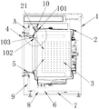
fig. 1 is a sectional view of a drum washing machine according to a first embodiment of the present invention;
FIG. 2 is an enlarged view of portion A of FIG. 1;
FIG. 3 is a sectional view of a second embodiment of the drum washing machine according to the present invention;
FIG. 4 is an enlarged view of portion A of FIG. 3;
fig. 5 is a sectional view of a third embodiment of the drum washing machine of the present invention;
fig. 6 is an enlarged view of a portion a in fig. 5.
List of reference numerals:
1. a box body; 2. an outer cylinder; 21. the edge of the outer cylinder mouth; 3. an inner barrel; 4. a door body; 5. sealing the window gasket; 6. draining pump; 7. a drain pipe; 8. a circulation pump; 9. a water outlet pipe; 10. an annular water channel; 101. an annular rib; 102. an ejection port; 103. and a flow guide structure.
Detailed Description
It should be understood by those skilled in the art that the embodiments of the present invention are only for explaining the technical principle of the present invention, and are not intended to limit the scope of the present invention. For example, although the present invention has been described with respect to an injection hole having a flat structure, the injection hole of the present invention may be an injection hole having any other structure. Those skilled in the art can make modifications as needed to suit a particular application, and such modified embodiments will still fall within the scope of the present invention.
It should also be noted that, in the description of the present invention, unless otherwise explicitly specified or limited, the terms "mounted," "connected," and "connected" are to be construed broadly, e.g., as meaning either a fixed connection, a removable connection, or an integral connection; can be mechanically or electrically connected; they may be connected directly or indirectly through intervening media, or they may be interconnected between two elements. The specific meanings of the above terms in the present invention can be understood by those skilled in the art according to specific situations.
Referring to fig. 1, fig. 1 is a sectional view of a drum washing machine according to a first embodiment of the present invention. As shown in fig. 1, the drum washing machine of the present invention mainly includes a cabinet 1, an outer tub 2, an inner tub 3, a door 4, a sealing window gasket 5, a drain pump 6, and a drain pipe 7. Wherein the outer cylinder 2 is fixedly disposed inside the cabinet 1, the inner cylinder 3 is rotatably disposed in the outer cylinder 2, and the sealing window gasket 5 is disposed between the cabinet 1 and the outer cylinder 2. The drain pump 6 and the drain pipe 7 are both arranged in the box body 1, a water inlet of the drain pump 6 leads to the inner bottom of the outer cylinder 2, a water outlet of the drain pump 6 is connected with one end of the drain pipe 7, and the other end of the drain pipe 7 leads to the outside. The drain pump 6 can drain the washing water in the outer tub 2 through the drain pipe 7.
Further, as will be understood by those skilled in the art, when each portion of the drain pipe 7 is lower than the inner bottom end of the outer tub 2, those skilled in the art can omit the drain pump 6 and replace the drain pump 6 with a shut-off valve as needed. When the drum washing machine needs to drain, the cut-off valve is opened, so that the washing water in the outer tub 2 is automatically drained from the drain pipe 7 under the action of self gravity.
With continued reference to fig. 1, the front end of the box body 1 (left side of the box body 1 in fig. 1) is provided with a box body opening (not shown), the front end of the outer cylinder 2 (left side of the outer cylinder 2 in fig. 1) is provided with an outer cylinder opening (not shown), and the front end of the inner cylinder 3 (left side of the inner cylinder 3 in fig. 1) is provided with an inner cylinder opening (not shown). One end of the sealing window gasket 5 is connected with the edge of the outer cylinder opening in a sealing way, and the other end of the sealing window gasket 5 is connected with the edge of the inner cylinder opening in a sealing way. The door 4 is pivotally provided on the cabinet 1, and the door 4 can close the cabinet opening when closed, preventing the washing water in the tub 2 from overflowing from the cabinet opening.
As shown in fig. 1, the drum washing machine of the present invention further comprises a spraying system mainly comprising a circulation pump 8, a water outlet pipe 9, and an annular water retaining structure disposed between the inner wall of the outer tub 2 and the outer wall of the inner tub (such as an annular rib 101 shown in fig. 1), and thus an annular water passage 10 having a spray opening 102 is formed between the rim 21 of the outer tub opening and the annular rib 101. Wherein the circulation pump 8 is preferably arranged within the tank 1 and fixedly connected to the tank 1. Alternatively, the circulation pump 8 may be fixedly connected to the outer tub 1 as required by those skilled in the art. The water inlet of the circulating pump 8 is open to the inside of the outer barrel 2, and preferably, the water inlet of the circulating pump 8 is connected with the bottom end of the outer barrel 2 through a water inlet pipe. Or the person skilled in the art can connect the water inlet pipe to any position of the outer cylinder 2, if necessary, while ensuring that the water inlet pipe is located below the liquid level in the outer cylinder 2. The water outlet of the circulating pump 8 is communicated with the annular water channel 10 through a water outlet pipe 9. In operation of the spray system of the present invention, as shown by the arrows in fig. 1, the circulation pump 8 pumps the washing water in the outer tub 2 to the circular water passage 10, and the washing water entering the circular water passage 10 is sprayed into the inner tub 3 through the spray ports 102. When the tub 3 is operated at a high speed, the water stream ejected from the ejection port 102 can rapidly pass through the laundry and enter the tub 2 by centrifugal force and gravity.
Referring to fig. 2, fig. 2 is an enlarged view of a portion a in fig. 1. As shown in fig. 2, in the present embodiment, an annular rib 101 is provided on the inner wall of the outer cylinder 2. Thus, the annular water passage 10 is formed between the rim 21 of the outer cylindrical opening and the annular rib 101, and the ejection port 102 is formed between the cylindrical openings in the rim 21 of the outer cylindrical opening. Those skilled in the art can set the specific position of the annular rib 101 according to the practical application of the washing machine, such as setting the annular rib 101 at the edge 21 close to the outer cylinder mouth to reduce the inner diameter of the formed annular water channel 10, or setting the annular rib 101 at the edge 21 far from the outer cylinder mouth to increase the inner diameter of the formed annular water channel 10.
Preferably, the injection port 102 is provided with a flow guide structure 103, and the flow guide structure 103 is used for injecting the washing water entering the annular water channel 10 into the inner tub 3 in the form of an annular waterfall water flow. As an example, the flow guiding structure 103 may be arranged on the edge 21 of the outer socket (which is the case when the flow guiding structure 103 is arranged on the edge 21 of the outer socket as shown in fig. 2), or the flow guiding structure 103 may also be arranged on the sealing window gasket 5. In other words, the skilled person can flexibly set the position of the flow guide structure 10 as long as the flow guide structure 10 can achieve the purpose of guiding the washing water flowing out of the circular water passage 10.
In addition to the above embodiments, fig. 3 to 6 show other embodiments of the present invention.
Referring to fig. 3 and 4, fig. 3 is a sectional view of a second embodiment of a drum washing machine according to the present invention; fig. 4 is an enlarged view of a portion a in fig. 3. In this embodiment, the difference from the first embodiment is that the annular rib 10 is provided on the outer wall of the inner cylinder 3.
Referring to fig. 5 and 6, fig. 5 is a sectional view of a third embodiment of a drum washing machine according to the present invention; fig. 6 is an enlarged view of a portion a in fig. 5. In this embodiment, the difference from the first embodiment is that the outer wall of the inner cylinder 3 and the inner wall of the outer cylinder 2 are provided with annular ribs 10.
It should be noted that, although the annular rib is taken as an example for the description of the annular water retaining structure of the present invention, a person skilled in the art may design the annular water retaining structure into other forms of structures, such as a sheet, a cylinder, a hollow structure, etc., according to actual design requirements, and even may set the annular water retaining structure into a special-shaped ring (for example, the distance between the annular water retaining structure and the edge of the outer cylinder opening is in a variation trend, that is, the formed annular water channel 10 has a plurality of different inner diameters), which do not depart from the protection scope of the present invention.
It should also be noted that the drain pump 6 and/or the circulation pump 8 of the present invention may be any feasible pump, such as a gear pump, a vane pump, a peristaltic pump, a centrifugal pump, etc.
It will be appreciated by those skilled in the art that in another possible embodiment of the invention, the drain pump 6 and the circulation pump 8 may be replaced by one pump. As an example one, the drain pump 6 is omitted, the water outlet of the circulation pump 8 is made to communicate with the water outlet pipe 9 and the water discharge pipe 7, respectively, and the water outlet pipe 9 is provided with a first cut-off valve for selectively opening or closing it, and the water discharge pipe 7 is provided with a second cut-off valve for selectively opening or closing it. When the drum washing machine executes the spraying operation, the first stop valve is opened, and the second stop valve is closed; when the drum washing machine performs a draining operation, the first cut-off valve is closed and the second cut-off valve is opened. As example two, the drain pump 6 is omitted and a three-way valve is provided for the water outlet of the circulation pump 8, so that the water outlet of the circulation pump 8 can be selectively communicated with the water outlet pipe 9 or the water outlet pipe 7 by means of the three-way valve. In addition, a person skilled in the art can also make the three-way valve capable of blocking the communication between the circulation pump 8 and the water outlet pipe 9 and the communication between the circulation pump 8 and the water discharge pipe 7 at the same time as required.
As described above, the present invention forms the annular water channel between the edge 21 of the outer cylinder opening and the annular rib 101 by arranging the annular rib 101 on the inner wall of the outer cylinder 2 and/or the outer wall of the inner cylinder 3, and has a simple structure, and does not need to separately arrange the circulating water channel, thereby greatly reducing the manufacturing cost of the washing machine. Also, the circular waterway 10 formed in the present invention is provided with the injection ports 102, and it is not necessary to separately provide an injection device for injecting the washing water. In addition, as a preferred example, the jet port 102 of the present invention realizes the jet effect of the circular waterfall water flow by providing the flow guiding structure 103, and the jet effect can rapidly penetrate through the laundry, thereby greatly improving the rinsing rate.
In addition, the invention also provides a drum washing machine, which comprises a washing machine body and the spraying system for the drum washing machine. For the specific embodiment of the drum washing machine, reference is made to the above description, which is not repeated herein.
So far, the technical solutions of the present invention have been described in connection with the preferred embodiments shown in the drawings, but it is easily understood by those skilled in the art that the scope of the present invention is obviously not limited to these specific embodiments. Equivalent changes or substitutions of related technical features can be made by those skilled in the art without departing from the principle of the invention, and the technical scheme after the changes or substitutions can fall into the protection scope of the invention.
Claims (6)
1. A spraying system for a roller washing machine comprises a box body, an outer barrel and an inner barrel which are arranged in sequence from outside to inside,
the spraying system is characterized by comprising a circulating pump, a water outlet pipe and an annular water retaining structure, wherein the annular water retaining structure is an annular rib;
the annular rib is arranged between the inner wall of the outer cylinder and the outer wall of the inner cylinder, so that an annular water channel with a jet orifice is formed between the edge of the outer cylinder opening and the annular rib, and the jet orifice is formed between the edge of the outer cylinder opening and the inner cylinder opening;
the annular ribs are arranged on the edge close to the outer cylinder opening to reduce the inner diameter of the formed annular water channel, or the annular ribs are arranged on the edge far away from the outer cylinder opening to increase the inner diameter of the formed annular water channel;
a water inlet of the circulating pump is communicated with the inner part of the outer barrel, and a water outlet of the circulating pump is communicated with the annular water channel through the water outlet pipe;
when the washing machine works, the circulating pump pumps the washing water in the outer barrel to the annular water channel, and the washing water is sprayed into the inner barrel through the spray opening;
the annular ribs are arranged on the inner wall of the outer barrel, the outer wall of the inner barrel or between the inner wall of the outer barrel and the outer wall of the inner barrel;
the inner cylinder is provided with an annular water channel, and the annular water channel is communicated with the inner cylinder through the annular water channel.
2. The spraying system for a drum washing machine according to claim 1, characterized in that the flow guide structure is provided at the edge of the outer drum opening.
3. The spraying system for a drum washing machine according to claim 2, characterized in that a sealing window gasket is arranged between the tank opening and the outer drum opening of the drum washing machine, and the flow guide structure is arranged on the sealing window gasket.
4. The spraying system for a drum washing machine according to any one of claims 1 to 3, characterized in that the water outlet of the circulation pump is also in communication with the drain pipe of the drum washing machine;
the water outlet pipe is provided with a first stop valve for selectively opening or closing the water outlet pipe; the drain pipe is provided with a second shut-off valve for selectively opening or closing the drain pipe.
5. The spraying system for a drum washing machine according to claim 4, characterized in that the spraying system further comprises a three-way valve by which the water outlet of the circulation pump is selectively communicated with the water outlet pipe or the water discharge pipe.
6. A drum washing machine comprising a washing machine body, characterized in that it further comprises a spraying system for a drum washing machine according to any one of claims 1 to 5.
Priority Applications (4)
| Application Number | Priority Date | Filing Date | Title |
|---|---|---|---|
| CN201810336205.5A CN110387705B (en) | 2018-04-16 | 2018-04-16 | Roller washing machine and spraying system thereof |
| JP2020557185A JP7079344B2 (en) | 2018-04-16 | 2019-04-09 | Drum washing machine and its spray system |
| PCT/CN2019/081883 WO2019201117A1 (en) | 2018-04-16 | 2019-04-09 | Front-loading washer and spray system thereof |
| JP2022082461A JP7392039B2 (en) | 2018-04-16 | 2022-05-19 | Drum washing machine and its spray system |
Applications Claiming Priority (1)
| Application Number | Priority Date | Filing Date | Title |
|---|---|---|---|
| CN201810336205.5A CN110387705B (en) | 2018-04-16 | 2018-04-16 | Roller washing machine and spraying system thereof |
Publications (2)
| Publication Number | Publication Date |
|---|---|
| CN110387705A CN110387705A (en) | 2019-10-29 |
| CN110387705B true CN110387705B (en) | 2022-04-15 |
Family
ID=68283719
Family Applications (1)
| Application Number | Title | Priority Date | Filing Date |
|---|---|---|---|
| CN201810336205.5A Active CN110387705B (en) | 2018-04-16 | 2018-04-16 | Roller washing machine and spraying system thereof |
Country Status (1)
| Country | Link |
|---|---|
| CN (1) | CN110387705B (en) |
Citations (4)
| Publication number | Priority date | Publication date | Assignee | Title |
|---|---|---|---|---|
| CN1948596A (en) * | 2005-10-13 | 2007-04-18 | 松下电器产业株式会社 | Drum-type washing machine and washing method using the same |
| JP2010036016A (en) * | 2008-07-09 | 2010-02-18 | Panasonic Corp | Drum washing machine |
| CN201785630U (en) * | 2009-09-08 | 2011-04-06 | 松下电器产业株式会社 | Drum washing machine |
| CN106400392A (en) * | 2015-07-30 | 2017-02-15 | 青岛海尔滚筒洗衣机有限公司 | Drum-type washing machine and control method thereof |
Family Cites Families (2)
| Publication number | Priority date | Publication date | Assignee | Title |
|---|---|---|---|---|
| CN102733155B (en) * | 2012-06-02 | 2015-03-11 | 松下家电研究开发(杭州)有限公司 | Washing machine with preposed water inlet drum |
| CN107815820A (en) * | 2017-11-03 | 2018-03-20 | 青岛海尔洗衣机有限公司 | The outer bung of washing-drying integral machine and wash dry integral clothing machine and method of work with it |
-
2018
- 2018-04-16 CN CN201810336205.5A patent/CN110387705B/en active Active
Patent Citations (4)
| Publication number | Priority date | Publication date | Assignee | Title |
|---|---|---|---|---|
| CN1948596A (en) * | 2005-10-13 | 2007-04-18 | 松下电器产业株式会社 | Drum-type washing machine and washing method using the same |
| JP2010036016A (en) * | 2008-07-09 | 2010-02-18 | Panasonic Corp | Drum washing machine |
| CN201785630U (en) * | 2009-09-08 | 2011-04-06 | 松下电器产业株式会社 | Drum washing machine |
| CN106400392A (en) * | 2015-07-30 | 2017-02-15 | 青岛海尔滚筒洗衣机有限公司 | Drum-type washing machine and control method thereof |
Also Published As
| Publication number | Publication date |
|---|---|
| CN110387705A (en) | 2019-10-29 |
Similar Documents
| Publication | Publication Date | Title |
|---|---|---|
| CN110387707B (en) | Roller washing machine and door body and spraying system thereof | |
| CN110359229B (en) | Bidirectional washing drum, washing machine and control method | |
| EP2778272A1 (en) | Drainage pump device for washing machine and washing machine therewith | |
| WO2019214517A1 (en) | Drum washing machine and spraying system thereof | |
| JP7392039B2 (en) | Drum washing machine and its spray system | |
| CN110387705B (en) | Roller washing machine and spraying system thereof | |
| CN110387699B (en) | Roller washing machine and spraying system thereof | |
| CN208562852U (en) | Roller washing machine and its spray system | |
| CN110387706B (en) | Roller washing machine and spraying system thereof | |
| WO2019201116A1 (en) | Front-loading washer and spray system thereof | |
| WO2019214515A1 (en) | Drum washing machine, and spraying system and sealed window pad thereof | |
| WO2019201118A1 (en) | Front-loading washer and spray system thereof | |
| WO2019201119A1 (en) | Front-loading washer and spray system thereof | |
| CN110468554B (en) | Drum washing machine and spraying control method thereof | |
| WO2019237948A1 (en) | Front-loading washing machine and spraying system and sealing window gasket thereof | |
| CN208562873U (en) | Roller washing machine and its spray system | |
| CN110387712A (en) | Roller washing machine and its spray system | |
| CN209066157U (en) | Rotary drum washing machine and its spray system | |
| CN208266504U (en) | Roller washing machine and its spray system | |
| CN110387708A (en) | Roller washing machine and its spray system | |
| WO2019201114A1 (en) | Front-loading washer and spray system thereof | |
| CN111607932A (en) | Drum washing machine | |
| JP7293373B2 (en) | drum washing machine | |
| CN110607663B (en) | Roller washing machine and spraying system and outer barrel thereof | |
| CN110468551B (en) | Drum washing machine and spraying control method thereof |
Legal Events
| Date | Code | Title | Description |
|---|---|---|---|
| PB01 | Publication | ||
| PB01 | Publication | ||
| SE01 | Entry into force of request for substantive examination | ||
| SE01 | Entry into force of request for substantive examination | ||
| TA01 | Transfer of patent application right |
Effective date of registration: 20220309 Address after: 266101 south side of Tuanjie road and west side of zonger Road, Huangdao District, Qingdao City, Shandong Province Applicant after: QINGDAO HAIER WASHING ELECTRIC APPLIANCES Co.,Ltd. Applicant after: Haier Zhijia Co., Ltd Address before: 266101 Haier Industrial Park, 1 Haier Road, Laoshan District, Shandong, Qingdao Applicant before: QINGDAO HAIER DRUM WASHING MACHINE Co.,Ltd. |
|
| TA01 | Transfer of patent application right | ||
| GR01 | Patent grant | ||
| GR01 | Patent grant |