JP5909754B2 - Solar panel fixing structure - Google Patents
Solar panel fixing structure Download PDFInfo
- Publication number
- JP5909754B2 JP5909754B2 JP2011270491A JP2011270491A JP5909754B2 JP 5909754 B2 JP5909754 B2 JP 5909754B2 JP 2011270491 A JP2011270491 A JP 2011270491A JP 2011270491 A JP2011270491 A JP 2011270491A JP 5909754 B2 JP5909754 B2 JP 5909754B2
- Authority
- JP
- Japan
- Prior art keywords
- solar panel
- pivot
- fixed
- panel fixing
- support rail
- Prior art date
- Legal status (The legal status is an assumption and is not a legal conclusion. Google has not performed a legal analysis and makes no representation as to the accuracy of the status listed.)
- Active
Links
Images


Classifications
-
- F—MECHANICAL ENGINEERING; LIGHTING; HEATING; WEAPONS; BLASTING
- F24—HEATING; RANGES; VENTILATING
- F24S—SOLAR HEAT COLLECTORS; SOLAR HEAT SYSTEMS
- F24S25/00—Arrangement of stationary mountings or supports for solar heat collector modules
- F24S25/10—Arrangement of stationary mountings or supports for solar heat collector modules extending in directions away from a supporting surface
- F24S25/13—Profile arrangements, e.g. trusses
-
- F—MECHANICAL ENGINEERING; LIGHTING; HEATING; WEAPONS; BLASTING
- F24—HEATING; RANGES; VENTILATING
- F24S—SOLAR HEAT COLLECTORS; SOLAR HEAT SYSTEMS
- F24S25/00—Arrangement of stationary mountings or supports for solar heat collector modules
- F24S25/60—Fixation means, e.g. fasteners, specially adapted for supporting solar heat collector modules
- F24S25/61—Fixation means, e.g. fasteners, specially adapted for supporting solar heat collector modules for fixing to the ground or to building structures
-
- Y—GENERAL TAGGING OF NEW TECHNOLOGICAL DEVELOPMENTS; GENERAL TAGGING OF CROSS-SECTIONAL TECHNOLOGIES SPANNING OVER SEVERAL SECTIONS OF THE IPC; TECHNICAL SUBJECTS COVERED BY FORMER USPC CROSS-REFERENCE ART COLLECTIONS [XRACs] AND DIGESTS
- Y02—TECHNOLOGIES OR APPLICATIONS FOR MITIGATION OR ADAPTATION AGAINST CLIMATE CHANGE
- Y02B—CLIMATE CHANGE MITIGATION TECHNOLOGIES RELATED TO BUILDINGS, e.g. HOUSING, HOUSE APPLIANCES OR RELATED END-USER APPLICATIONS
- Y02B10/00—Integration of renewable energy sources in buildings
- Y02B10/10—Photovoltaic [PV]
-
- Y—GENERAL TAGGING OF NEW TECHNOLOGICAL DEVELOPMENTS; GENERAL TAGGING OF CROSS-SECTIONAL TECHNOLOGIES SPANNING OVER SEVERAL SECTIONS OF THE IPC; TECHNICAL SUBJECTS COVERED BY FORMER USPC CROSS-REFERENCE ART COLLECTIONS [XRACs] AND DIGESTS
- Y02—TECHNOLOGIES OR APPLICATIONS FOR MITIGATION OR ADAPTATION AGAINST CLIMATE CHANGE
- Y02E—REDUCTION OF GREENHOUSE GAS [GHG] EMISSIONS, RELATED TO ENERGY GENERATION, TRANSMISSION OR DISTRIBUTION
- Y02E10/00—Energy generation through renewable energy sources
- Y02E10/40—Solar thermal energy, e.g. solar towers
- Y02E10/47—Mountings or tracking
-
- Y—GENERAL TAGGING OF NEW TECHNOLOGICAL DEVELOPMENTS; GENERAL TAGGING OF CROSS-SECTIONAL TECHNOLOGIES SPANNING OVER SEVERAL SECTIONS OF THE IPC; TECHNICAL SUBJECTS COVERED BY FORMER USPC CROSS-REFERENCE ART COLLECTIONS [XRACs] AND DIGESTS
- Y02—TECHNOLOGIES OR APPLICATIONS FOR MITIGATION OR ADAPTATION AGAINST CLIMATE CHANGE
- Y02E—REDUCTION OF GREENHOUSE GAS [GHG] EMISSIONS, RELATED TO ENERGY GENERATION, TRANSMISSION OR DISTRIBUTION
- Y02E10/00—Energy generation through renewable energy sources
- Y02E10/50—Photovoltaic [PV] energy
Description
本発明は、例えば、屋上やバルコニー等の取付下地上に、ソーラーパネルを固定するソーラーパネル固定構造に関し、更に詳しくは、ソーラーパネルの対向する縁部にそれぞれ被固定部を設け、前記被固定部に対応するパネル固定部を取付下地にそれぞれ設け、前記パネル固定部に前記被固定部をそれぞれ連結して前記ソーラーパネルが取付下地に固定されているソーラーパネル固定構造に関する。 The present invention relates to, for example, a solar panel fixing structure for fixing a solar panel on a mounting base such as a rooftop or a balcony. More specifically, the fixed portion is provided at each of the opposing edges of the solar panel, and the fixed portion is provided. A panel fixing portion corresponding to the above is provided on the mounting base, and the fixed portion is connected to the panel fixing portion to fix the solar panel to the mounting base.
従来、この種のソーラーパネル固定構造としては、図11に示すように、傾斜状態に固定されるソーラーパネルPの傾斜上手縁部PLと傾斜下手縁部PLにそれぞれ被固定部Hが設けられ、取付下地2には、各被固定部Hに対応するパネル固定部1がそれぞれ設けられ、傾斜上手縁部PLの被固定部Hと、対応するパネル固定部1とについてのみ、ソーラーパネルPを上下揺動可能に支持する枢支連結部Jによって連結してあるものがあった。
因みに、傾斜下手縁部PLの被固定部Hと、対応するパネル固定部1とは、単に固定状態に連結されている。
また、枢支連結部Jの構造は、図11に示すように、被固定部Hに備えた半割れパイプ状の内嵌部30と、パネル固定部1に備えた半割れパイプ状の外嵌部31とを、内外に嵌合させて、外嵌部31に形成されたスリット部32から被固定部Hの板部33が立ち上がる状態に構成され、外嵌部31に対して内嵌部30が周方向に回動することで、ソーラーパネルPを揺動可能に枢支連結してあった。
Conventionally, as this type of solar panel fixing structure, as shown in FIG. 11, a fixed portion H is provided on each of the inclined upper hand edge PL and the inclined lower hand edge PL of the solar panel P fixed in an inclined state, The
Incidentally, the fixed part H of the inclined lower edge part PL and the corresponding
Further, as shown in FIG. 11, the structure of the pivot connecting portion J includes a half-cracked pipe-like
上述した従来のソーラーパネル固定構造によれば、枢支連結部を、ソーラーパネルの傾斜上手縁部での被固定部とパネル固定部とに設けてあるから、その枢支連結部の枢支軸芯周りにソーラーパネルを上下揺動操作することが可能である。
従って、ソーラーパネルの裏面側において各種メンテナンス作業(例えば、配線関係の着脱やメンテナンス作業や、取付下地の防水層の改修作業やメンテナンス作業等)を実施する際には、ソーラーパネルを枢支連結部周りに揺動させて、ソーラーパネルの裏面側空間を開放して、メンテナンス作業を実施しやすくすることが可能となる。
According to the conventional solar panel fixing structure described above, the pivot connecting portion is provided at the fixed portion and the panel fixing portion at the inclined upper edge portion of the solar panel, so the pivot shaft of the pivot connecting portion is provided. It is possible to swing the solar panel up and down around the core.
Therefore, when performing various maintenance work on the back side of the solar panel (for example, wiring attachment / detachment and maintenance work, repair work and maintenance work on the waterproof layer of the mounting base, etc.), the solar panel should be pivotally connected. By swinging around, the space on the back side of the solar panel can be opened to facilitate the maintenance work.
しかしながら、従来のソーラーパネル固定構造によれば、ソーラーパネルの傾斜下手縁部側の裏面空間は、全て開放することができるものの、傾斜上手縁部側には、枢支連結部が位置しているから、ソーラーパネルと取付下地との間は、狭小空間のまま残されることになり、その箇所でのメンテナンス作業やその他の作業が実施し難い問題点がある。
例えば、ソーラーパネルの裏面側の配線やコネクタ等に関しては、パネルによっては、傾斜上手縁部側に位置させてある場合があるから、配線関係の着脱作業やメンテナンス作業を、ソーラーパネルと取付下地との間の狭小空間で行う必要があり、作業効率が低下しやすい虞がある。
また、取付下地の防水層の改修作業やメンテナンス作業に関しても、同様であり、作業効率が低下しやすい虞がある。
However, according to the conventional solar panel fixing structure, the back space on the inclined lower hand edge side of the solar panel can be completely opened, but the pivot connection part is located on the inclined upper hand edge side. Therefore, the space between the solar panel and the mounting base is left as it is in a small space, and there is a problem that it is difficult to perform maintenance work and other work in that place.
For example, with regard to wiring and connectors on the back side of the solar panel, depending on the panel, there are cases where it is located on the inclined upper edge side, so wiring-related attachment and detachment work and maintenance work can be done with the solar panel and the mounting base. It is necessary to carry out in the narrow space between, and there exists a possibility that work efficiency may fall easily.
The same applies to the repair work and maintenance work of the waterproof layer of the mounting base, and there is a possibility that the work efficiency is likely to be lowered.
従って、本発明の目的は、上記問題点を解消し、ソーラーパネルの裏面側の何れの箇所においても、各種メンテナンス作業を効率よく実施できるソーラーパネル固定構造を提供するところにある。 Accordingly, an object of the present invention is to provide a solar panel fixing structure that solves the above-described problems and can efficiently perform various maintenance operations at any location on the back side of the solar panel.
本発明の第1の特徴構成は、ソーラーパネルの対向する縁部にそれぞれ被固定部を設け、前記被固定部に対応するパネル固定部を取付下地にそれぞれ設け、前記パネル固定部に前記被固定部をそれぞれ連結して前記ソーラーパネルが取付下地に固定されているソーラーパネル固定構造であって、前記パネル固定部は、前記ソーラーパネルの対向する縁部の長手方向に沿う状態で、且つ、平行な状態で前記取付下地にそれぞれ固定される一対の支持レールと、前記長手方向に沿って移動可能な状態で前記支持レールに支持される枢支ピースと、を備え、前記枢支ピースと前記被固定部とは、前記一対の支持レールの何れ側においても、締結具を、前記長手方向に沿って前記枢支ピースと前記被固定部とに亘って締結することで、前記締結具周りに揺動可能な状態で連結してあり、前記ソーラーパネルは、前記一対の支持レールのうち何れか一方側の支持レール側において前記締結具を取り外すことで、前記一対の支持レールのうち他方側の支持レール側における前記締結具を枢支軸芯として揺動可能であるところにある。
また、本発明の第2の特徴構成は、ソーラーパネルの対向する縁部にそれぞれ被固定部を設け、前記被固定部に対応するパネル固定部を取付下地にそれぞれ設け、前記パネル固定部に前記被固定部をそれぞれ連結して前記ソーラーパネルが取付下地に固定されているソーラーパネル固定構造であって、前記パネル固定部と前記被固定部とは、枢支軸芯周りに揺動可能な枢支連結部によってそれぞれ連結してあり、前記枢支連結部は、前記枢支軸芯が前記ソーラーパネルの対向する縁部の長手方向に沿うように形成してあり、前記ソーラーパネルは、何れか一方の前記枢支連結部を取り外すことで、他方の前記枢支連結部の枢支軸芯周りに揺動可能な状態に取り付けてあり、前記枢支連結部は、着脱自在な枢支軸部材を備え、前記パネル固定部は、前記枢支軸部材を取り付ける枢支ピースと、前記枢支ピースを前記ソーラーパネルの対向する縁部の長手方向に沿って移動可能に支持する支持レールとを備え、前記枢支軸部材を前記枢支ピースに取り付ける操作に連動して、前記支持レールに対する前記枢支ピースの移動を規制する移動規制機構が設けてあるところにある。
The first characteristic configuration of the present invention is that a fixed portion is provided at each facing edge of the solar panel, a panel fixing portion corresponding to the fixed portion is provided on a mounting base, and the fixed portion is attached to the panel fixing portion. A solar panel fixing structure in which the solar panel is fixed to a mounting base by connecting the respective parts, wherein the panel fixing part is in a state along the longitudinal direction of the opposing edge of the solar panel and in parallel A pair of support rails that are respectively fixed to the mounting base in a state of being fixed, and a pivot piece that is supported by the support rail in a state of being movable along the longitudinal direction. The fixed portion is a portion around the fastener by fastening the fastener over the pivot piece and the fixed portion along the longitudinal direction on either side of the pair of support rails. The solar panel is connected in a swingable state, and the solar panel is attached to the other side of the pair of support rails by removing the fastener on the support rail side of either side of the pair of support rails. The fastener on the side of the support rail is capable of swinging with the pivot axis.
Further, the second characteristic configuration of the present invention is that a fixed portion is provided at each facing edge of the solar panel, a panel fixing portion corresponding to the fixed portion is provided on a mounting base, and the panel fixing portion A solar panel fixing structure in which the solar panel is fixed to a mounting base by connecting fixed parts, respectively, wherein the panel fixing part and the fixed part are pivotable about a pivot axis. The pivot connecting portions are respectively connected by a branch connecting portion, and the pivot supporting portion is formed so that the pivot axis is along the longitudinal direction of the facing edge of the solar panel. By removing one of the pivot connection parts, the pivot connection part is attached in a swingable manner around the pivot axis of the other pivot connection part, and the pivot connection part is a detachable pivot shaft member The panel fixing part A pivot piece for attaching the pivot shaft member; and a support rail for movably supporting the pivot piece along the longitudinal direction of the opposing edges of the solar panel; and A movement restricting mechanism for restricting the movement of the pivot piece with respect to the support rail is provided in conjunction with the operation of attaching to the pivot piece .
本発明の第2の特徴構成によれば、それぞれのパネル固定部と被固定部とが枢支連結部によって連結してあるから、ソーラーパネルの対向する縁部の一方の枢支連結部を取り外せば、他方の枢支連結部の枢支軸芯周りにソーラーパネルを揺動させることができ、また、一方の枢支連結部を連結状態に保つと共に他方の枢支連結部を取り外せば、一方の枢支連結部の枢支軸芯周りにソーラーパネルを揺動させることができる。
即ち、ソーラーパネルは、何れの枢支連結部においてもその枢支軸芯周りに揺動操作することが可能となるから、ソーラーパネルの裏面側の何れの箇所をも開放することができ、各種メンテナンス作業(例えば、配線関係の着脱やメンテナンス作業や、取付下地の防水層の改修作業やメンテナンス作業等)を効率よく実施できる。
また、ソーラーパネルを各枢支軸芯が平行(又は、ほぼ平行)になるような状態で複数列にわたって設置してあるような場合、隣合う列に位置するソーラーパネルどうしを、枢支軸芯方向視によって「ハ」の字となるように上方に揺動させれば、それら隣接ソーラーパネルの下方にそれぞれ開放される空間が連続した広い開放空間となり、更に効率よく上記各種メンテナンス作業を実施することができる。
また、ソーラーパネルの対向する縁部のそれぞれの枢支連結部を連結状態にすることで、ソーラーパネルを揺動しない安定した支持状態で取付下地に固定することができる。
According to the second characteristic configuration of the present invention, since each panel fixing portion and the fixed portion are connected by the pivot connection portion, one of the pivot connection portions of the opposite edges of the solar panel can be removed. For example, the solar panel can be swung around the pivot axis of the other pivot joint, and if one pivot joint is kept connected and the other pivot joint is removed, The solar panel can be swung around the pivot axis of the pivot connection portion.
That is, since the solar panel can be swung around the pivot axis at any pivot connecting portion, any part on the back side of the solar panel can be opened. Maintenance work (for example, wiring-related attachment / detachment, maintenance work, repair work of the waterproof layer on the mounting base, maintenance work, etc.) can be performed efficiently.
In addition, when solar panels are installed in multiple rows with each pivot axis parallel (or almost parallel), the solar panels located in adjacent rows are connected to the pivot axis. If it is swung upwards so that it becomes a “C” shape when viewed from the direction, the space opened below each adjacent solar panel becomes a continuous wide open space, and the above-mentioned various maintenance operations are performed more efficiently. be able to.
Moreover, the solar panel can be fixed to the mounting base in a stable supporting state without swinging by connecting the pivot connecting portions of the opposing edge portions of the solar panel.
また、枢支軸部材を着脱操作するだけで、枢支連結部における揺動作用状態を簡単に切り替えることができる。
即ち、枢支軸部材は、枢支連結部における回動軸としての機能と、パネル固定部と被固定部とを一体に連結固定する機能とを担うことができ、部品の兼用化を叶えることができる。
また、枢支軸部材を取り外して劣化の度合を簡単にチェックしたり、場合によっては新しいものの取り替える等、部品のメンテナンスを簡単に実施することができる。
枢支軸部材の一例としては、ボルトであったり、ピン等が挙げられる。
Further , the swinging action state in the pivot connecting portion can be easily switched by simply attaching and detaching the pivot shaft member.
In other words, the pivot shaft member can have a function as a pivot shaft in the pivot connection portion and a function of integrally connecting and fixing the panel fixing portion and the fixed portion, thereby realizing the sharing of parts. Can do.
Also, it is possible to easily perform maintenance of parts such as removing the pivot shaft member and checking the degree of deterioration easily, or replacing a new one in some cases.
Examples of the pivot shaft member include a bolt and a pin.
また、支持レールによって枢支ピースを支持した状態で、支持レールの長手方向(ソーラーパネルの対向する縁部の長手方向)に沿って枢支ピースを移動することができる。
よって、ソーラーパネルを取付下地に取り付けた状態で、支持レールに沿って取り付き位置を移動させることができ、取り付け後でも位置調整を簡単に実施することができる。
よって、ソーラーパネルの取付作業の効率化を図ることができる。
In addition , the pivot piece can be moved along the longitudinal direction of the support rail (longitudinal direction of the opposite edge of the solar panel) while the pivot piece is supported by the support rail.
Therefore, the mounting position can be moved along the support rail in a state where the solar panel is mounted on the mounting base, and the position adjustment can be easily performed even after mounting.
Therefore, the efficiency of the solar panel mounting operation can be improved.
また、枢支軸部材を枢支ピースに取り付ける操作に伴って移動規制機構が作用して、支持レール上の枢支ピースの位置をロックすることができる。
即ち、枢支軸部材を枢支ピースに取り付ける一連の操作のみでソーラーパネルの位置のロックをも行うことができ、複雑な操作が不要となる。
よって、ソーラーパネルの取付作業の更なる効率化を図ることができる。
In addition , the movement restricting mechanism acts in accordance with the operation of attaching the pivot shaft member to the pivot piece, and the position of the pivot piece on the support rail can be locked.
That is, the position of the solar panel can be locked only by a series of operations for attaching the pivot shaft member to the pivot piece, and a complicated operation is unnecessary.
Therefore, further efficiency improvement of the solar panel mounting operation can be achieved.
以下に本発明の実施の形態を図面に基づいて説明する。尚、図面において従来例と同一の符号で表示した部分は、同一又は相当の部分を示している。 Embodiments of the present invention will be described below with reference to the drawings. In the drawings, the parts indicated by the same reference numerals as those in the conventional example indicate the same or corresponding parts.
図1は、本発明のソーラーパネル固定構造の一実施形態を示すものであり、ソーラーパネルPは、固定装置(パネル固定部に相当)1によって取付下地2に固定されている。
FIG. 1 shows an embodiment of a solar panel fixing structure of the present invention. A solar panel P is fixed to an
取付下地2は、本実施形態においては、コンクリート製の屋上スラブ2Aの上に防水層2Bを敷設して構成されている。防水層2Bの一例としては、塩化ビニル製のシート状のものが挙げられる。
但し、取付下地2は、このような構成に限るものではなく、例えば、屋上スラブ2Aと防水層2Bとの間に断熱材を配置した構成であったり、コンクリート製の屋上スラブ2Aに替えて折板屋根に使用される折板(金属板)を使用するものや、その上に断熱材が設けられたもの等、さまざまな対応が考えられる。
In the present embodiment, the
However, the
固定装置1は、取付下地2上に横間隔をあけて固定された接地部材1Cと、複数の接地部材1Cの上にわたる状態に取り付けられた支持レール1Bと、支持レール1Bに対してその長手方向に沿って移動可能に支持された枢支ピース1Aとを備えて構成してある。
枢支ピース1Aに、ソーラーパネルPの被固定部Hが取り付けられる。
The
The fixed portion H of the solar panel P is attached to the
接地部材1Cは、図2に示すように、円板形状の底面部5aと、その底面部5aの中央に立設された円柱部5bと、円柱部5bの外周に平面視十字配置で底面部5aにわたって形成された控え壁部5cと、前記円柱部5bに埋設されたボルト5dとを一体に設けて構成してある。そして、底面部5aの下面には、一回り大きめに成形された防水シート6が接着してあり、この防水シート6を屋上スラブ2A上の防水層2B上面に接着することで、当該接地部材1C設置部分の防水性の向上を図っている。尚、前記底面部5a、円柱部5b、控え壁部5cは、硬質の合成樹脂によって構成されている。
また、四つの前記控え壁部5cの内、支持レール1Bと直交配置となる二つの控え壁部5cには、図6に示すように、屋上スラブ2Aへねじ込んで接地部材1Cを固定するネジ部材7を挿入するための挿入部8が夫々設けられている。そして、この挿入部8へは、前記ネジ部材7を設置した後、シーリング材を充填すると共にキャップ9が設置される。
これらキャップ9の上には、支持レール1Bが載置状態に設置される。
As shown in FIG. 2, the
Further, among the four
On these
支持レール1Bは、当該実施形態においては、図2、図3に示すように、押出成形によって形成された長尺の金属形鋼で構成してある。
支持レール1Bは、左右に間隔をあけて立設された、一対の立壁部10と、前記一対の立壁部10の上下中間部どうしを一体に連結する連結板部11とを設けて構成してある。
各立壁部10の上縁部の内面には、枢支ピース1Aを嵌合させた状態でスライドを許容するアリ溝部10aが、対向する状態に設けてある。
各立壁部10の下縁部は、前述のようにキャップ9の上に載置される。
連結板部11には、接地部材1Cのボルト5dに対応したボルト挿通孔11aが形成してあり、このボルト挿通孔11aに、ボルト5dを挿通させてナット締めを行うことで、支持レール1Bが固定されている。
In this embodiment, the
The
On the inner surface of the upper edge portion of each standing
The lower edge portion of each standing
The connecting
枢支ピース1Aは、図3、図4に示すように、支持レール1Bの軸芯方向視において、左右側縁部に、支持レール1Bのアリ溝部10aに内嵌可能な先拡がりの突状部12aがそれぞれ設けてあると共に、突状部12aの基端部から上方に立ち上がって両突状部12aを連結する断面「A」字形状のピース本体部12bを設けて構成してある。
ピース本体部12bの上半部には、支持レール1Bの軸芯方向に沿って貫通するボルト貫通孔h0が形成してある。このボルト貫通孔h0には、後述するボルト(枢支軸部材に相当)Bを挿通させて(図4、図5、図7参照)、ソーラーパネルPのフレーム部材3をボルト軸芯周りに揺動操作可能に支持することができる。
As shown in FIGS. 3 and 4, the
A bolt through-hole h0 that penetrates along the axial direction of the
ソーラーパネルPは、図1に示すように、長方形板形状に構成してあり、表面部が太陽光を受ける受光部として構成されている(図6、図7参照)。
裏面部には、2つの桟状の金属製フレーム部材3が、短辺に平行に且つ長辺方向に間隔をあけてボルト固定してある。長辺方向での取付位置は、両端からそれぞれ中央側に入った位置に設定されており、このことにより、雨水がフレーム部材3にかかり難くなり、腐食防止効果によって耐久性の向上を図ることができる。
また、図には示さないが、ソーラーパネルPの裏面側にはコネクタや配線等が設けられている。
As shown in FIG. 1, the solar panel P is configured in a rectangular plate shape, and the surface portion is configured as a light receiving unit that receives sunlight (see FIGS. 6 and 7).
Two cross-shaped
Although not shown in the drawing, connectors, wirings, and the like are provided on the back side of the solar panel P.
フレーム部材3は、図8に示すように、ウェブ3Aと、ウェブ3Aの上縁からソーラーパネルPの中央側に屈曲した上フランジ3Bと、ウェブ3Aの下縁から前記上フランジ3Bとは反対側(ソーラーパネルPの短辺縁部PS側)に屈曲した下フランジ(移動規制機構の一例)3Cとから構成してある。
As shown in FIG. 8, the
上フランジ3Bは、ソーラーパネルPの裏面に沿わせてボルト固定されている。
The
ウェブ3Aは、図7に示すように、フレーム部材3の長手方向での一端部から他端部にかけて徐々に高さ寸法が小さくなるような台形形状に形成してあり、ソーラーパネルPを傾斜状態に取り付けられるように構成されている。
また、ウェブ3Aの長手方向での両端部側に、それぞれボルト(枢支軸部材に相当)Bを挿通可能なボルト貫通部3a,3bが形成してある。因みに、ボルトBは、フレーム部材3と固定装置1の枢支ピース1Aとを連結して枢支連結部Jを構成することができる。ボルトBの軸芯が、枢支連結部Jの枢支軸芯Xとなる(図6参照)。
ボルト貫通部3a,3bには、前記ボルトBの外径に合わせた丸穴のボルト貫通孔h1がそれぞれ設けられている。
ボルト貫通部3aとボルト貫通部3bとは、当該実施形態においては、一連のフレーム部材3の両端側に、ソーラーパネルPの対向する長辺縁部PLに対応させて設けてあり、本発明に係る被固定部Hに相当する。即ち、2つのボルト貫通部3a,3bを、1つのフレーム部材3に兼用化する状態で設けてあるものであり、部品点数の減小化を図ってある。従って、フレーム部材3とは別部材で、2つのボルト貫通部3a,3bを各別に設ける構成を採用することも可能である。
As shown in FIG. 7, the
Further, bolt through
The bolt through
In the present embodiment, the
因みに、上フランジ3Bとウェブ3Aとは、図8に示すように、交差角度が直角になるように屈曲させてあるのに対して、下フランジ部3Cとウェブ3Aとは、交差角度が鈍角(例えば、95度程度)になるように屈曲させてある。
従って、ソーラーパネルPを固定装置1の支持レール1Bの上にセットする際には、下フランジ部3Cの先端部から支持レール1Bに接触する。ウェブ3Aが支持レール1Bに接触するまでソーラーパネルPが下降すると、下フランジ部3Cが上方に撓み、下フランジ部3Cとウェブ3Aとの交差角度が直角に近い方向にフレーム部材3が弾性変形するから、その弾性復元力の作用で、下フランジ部3Cと支持レール1Bとの間に摩擦力が生じる。その状態で、枢支ピース1AからのボルトBをボルト貫通孔h1に挿通させて固定すると、支持レール1Bに対する枢支ピース1Aの移動を上述の摩擦力の作用で規制することができる。
このように形成されたフレーム部材3によって移動規制機構Kが構成されている。
Incidentally, as shown in FIG. 8, the
Accordingly, when the solar panel P is set on the
The movement restricting mechanism K is configured by the
次に、当該ソーラーパネルPの設置手順について説明する。
[1] 少なくとも2列配置となるように(図1参照)、屋上スラブ2A上の所定位置に接地部材1Cをそれぞれ配置して(図2参照)、ネジ部材7を挿入部8を通して屋上スラブ2Aにねじ込んで固定する(図6参照)。
その後、防水シート6を屋上スラブ2Aの防水層2Bに接着する。
また、挿入部8にシーリング材を充填してキャップ9を設置する。この工程によって、固定装置1の設置部分の防水性の維持を図ることが可能となる。
Next, the installation procedure of the solar panel P will be described.
[1] The
Thereafter, the
Further, the
[2] 設置された接地部材1Cの上方に支持レール1Bを配置する(図2,3参照)。配置においては、接地部材1Cから上方に突出しているボルト5dが、支持レール1Bのボルト挿痛穴11aを貫通するように支持レール1Bの位置合わせを行い、貫通させたボルト5dにナット5eを螺合して固定する(図2参照)。支持レール1Bは、少なくとも2列配置に設けられている。
[2] The
[3] 支持レール1Bの一対のアリ溝部10aに枢支ピース1Aの突状部12aを嵌合させて、支持レール1Bの長手方向での所定位置までスライドする。枢支ピース1Aは、1枚のソーラーパネルPを固定するのに、各フレーム部材3のボルト貫通部3a,3bに対応させて少なくとも4つ使用される。
[3] The
[4] 裏面にフレーム部材3を取り付けたソーラーパネルPを、2本の支持レール1Bにわたって載置し、ボルト貫通部3a,3bのボルト貫通孔h1と枢支ピース1Aのボルト貫通孔h0とを貫通する状態にボルトBを挿通させてナットBaを締め付けることでソーラーパネルPは、4点の枢支連結部Jで固定される(図4、図5参照)。このナットBaを締め付ける際に、図8に示すように、ソーラーパネルPを下方へ押圧するとフレーム部材3が長穴のボルト貫通孔h1に沿って下降し、フレーム部材3の下フランジ3Cが支持レール1Bの上面に沿う状態に押し付けられる。この状態で固定することでフレーム部材3と支持レール1Bとの摩擦抵抗を増加させて、ソーラーパネルPのずれ止めを図ることができる。
[4] The solar panel P with the
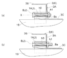
以上の手順で、ソーラーパネルPを取付下地2上に固定することができるが、ソーラーパネルPの裏面側での例えばメンテナンス等の作業を実施する場合には、図7の実線で示すように、一方側の支持レール1Bに対応したボルトBを取り外すと、他方側の支持レール1Bに対応したボルトBを回動軸芯としてソーラーパネルPを上方に揺動させることができる。また、図7の2点鎖線で示すように、他方側の支持レール1Bに対応したボルトBを取り外すと、一方側の支持レール1Bに対応したボルトBを回動軸芯としてソーラーパネルPを上方に揺動させることができ、ソーラーパネルPの裏面側での作業箇所に合わせて、作業のし易い方向にソーラーパネルPを上方に揺動させることができ、作業効率の向上を図ることができる。
尚、ソーラーパネルPを上方へ揺動させた状態を維持させるためには、例えば、ソーラーパネルP(又は、フレーム部材3)の揺動端部と、支持レール1Bとの間に、図には示していないが支持棒を配置する等の方法をとることが好ましい。
With the above procedure, the solar panel P can be fixed on the mounting
In order to maintain the state in which the solar panel P is swung upward, for example, between the swing end portion of the solar panel P (or the frame member 3) and the
〔別実施形態〕
以下に他の実施の形態を説明する。
[Another embodiment]
Other embodiments will be described below.
〈1〉 ソーラーパネルPの設置対象は、先の実施形態で説明した屋上スラブに限るものではなく、同様の屋上スラブであっても、その構造や形式の異なるものであってもよい。また、屋上スラブ以外にも、例えば、屋根や壁等もその設置対象とすることができる。
それらを含めて取付下地2と総称する。
〈2〉 パネル固定部1は、先の実施形態で説明した固定装置に限るものではなく、例えば、枢支ピース1Aと支持レール1Bとを備え、支持レール1Bを取付下地2に直に固定するように構成してあってもよい。また、各パーツの形状は、適宜変更することが可能である。
〈3〉 被固定部Hは、1つのフレーム部材3の両端にそれぞれ設けてある構成に限らず、個別に設けてあってもよい。
〈4〉 移動規制機構Kは、先の実施形態で説明したフレーム部材3によって構成するものに限らず、例えば、ウェブ3Aに形成したボルト貫通孔h1を、図9に示すような縦長の長穴として形成し、ボルトBとフレーム部材3とが上下に相対移動できるように構成してあってもよい。この場合、図9(a)に示すように、ボルト貫通孔h1にボルトBを仮固定した状態でフレーム部材3を浮かせることができ、支持レール1Bに沿って枢支ピース1Aをスムースにスライドさせて、固定位置の移動調整を簡単に実施することができる。位置が決まれば、長穴のボルト貫通孔h1に沿ってフレーム部材3を下降させてボルトBを本締めすることで(図9(b)参照)、下フランジ部3Cと支持レール1Bとの摩擦力が作用し、移動規制機構Kとしての機能を発揮させることができる。
また、移動規制機構Kの他の実施形態としては、例えば、図10に示すように、上フランジ3Bとウェブ3Aとの交差角度も、下フランジ3Cとウェブ3Aとの交差角度と同様に鈍角に形成しておき、ボルトBとナットBaとの螺合を深めるに伴って、ウェブ3Aを枢支ピース1Aに引き寄せながら、下フランジ3Cを支持レール1Bに押し付けられるように構成するものであってもよい。
<1> The installation target of the solar panel P is not limited to the roof slab described in the previous embodiment, and may be a similar roof slab or may have a different structure or form. In addition to the roof slab, for example, a roof or a wall can be set as the installation target.
These are collectively referred to as the mounting
<2> The
<3> The to-be-fixed part H is not restricted to the structure each provided in the both ends of the one
<4> The movement restricting mechanism K is not limited to the one configured by the
Further, as another embodiment of the movement restricting mechanism K, for example, as shown in FIG. 10, the crossing angle between the
尚、上述のように、図面との対照を便利にするために符号を記したが、該記入により本発明は添付図面の構成に限定されるものではない。また、本発明の要旨を逸脱しない範囲において、種々なる態様で実施し得ることは勿論である。 In addition, as mentioned above, although the code | symbol was written in order to make contrast with drawing convenient, this invention is not limited to the structure of an accompanying drawing by this entry. In addition, it goes without saying that the present invention can be carried out in various modes without departing from the gist of the present invention.
1 固定装置(パネル固定部に相当)
1A 枢支ピース
1B 支持レール
2 取付下地
B ボルト(枢支軸部材に相当)
H 被固定部
J 枢支連結部
K 移動規制機構
P ソーラーパネル
PL 長辺縁部(対向する縁部)
X 枢支軸芯
1 Fixing device (equivalent to panel fixing part)
H Fixed part J Pivot connection part K Movement control mechanism P Solar panel PL Long edge (opposite edge)
X pivot axis
Claims (2)
前記被固定部に対応するパネル固定部を取付下地にそれぞれ設け、
前記パネル固定部に前記被固定部をそれぞれ連結して前記ソーラーパネルが取付下地に固定されているソーラーパネル固定構造であって、
前記パネル固定部は、前記ソーラーパネルの対向する縁部の長手方向に沿う状態で、且つ、平行な状態で前記取付下地にそれぞれ固定される一対の支持レールと、前記長手方向に沿って移動可能な状態で前記支持レールに支持される枢支ピースと、を備え、
前記枢支ピースと前記被固定部とは、前記一対の支持レールの何れ側においても、締結具を、前記長手方向に沿って前記枢支ピースと前記被固定部とに亘って締結することで、前記締結具周りに揺動可能な状態で連結してあり、
前記ソーラーパネルは、前記一対の支持レールのうち何れか一方側の支持レール側において前記締結具を取り外すことで、前記一対の支持レールのうち他方側の支持レール側における前記締結具を枢支軸芯として揺動可能であるソーラーパネル固定構造。 Provide fixed parts at opposite edges of the solar panel,
A panel fixing portion corresponding to the fixed portion is provided on the mounting base,
A solar panel fixing structure in which the fixed portion is connected to the panel fixing portion and the solar panel is fixed to a mounting base,
The panel fixing portion is movable along the longitudinal direction and a pair of support rails that are respectively fixed to the mounting base in a state along the longitudinal direction of the opposing edges of the solar panel. A pivot piece supported by the support rail in a state,
The pivot piece and the fixed part are fastened to the pivot piece and the fixed part along the longitudinal direction on either side of the pair of support rails. , Connected in a swingable manner around the fastener,
The solar panel removes the fastener on the support rail side of one of the pair of support rails, thereby pivoting the fastener on the other support rail side of the pair of support rails. Solar panel fixing structure that can swing as a core .
前記被固定部に対応するパネル固定部を取付下地にそれぞれ設け、
前記パネル固定部に前記被固定部をそれぞれ連結して前記ソーラーパネルが取付下地に固定されているソーラーパネル固定構造であって、
前記パネル固定部と前記被固定部とは、枢支軸芯周りに揺動可能な枢支連結部によってそれぞれ連結してあり、
前記枢支連結部は、前記枢支軸芯が前記ソーラーパネルの対向する縁部の長手方向に沿うように形成してあり、
前記ソーラーパネルは、何れか一方の前記枢支連結部を取り外すことで、他方の前記枢支連結部の枢支軸芯周りに揺動可能な状態に取り付けてあり、
前記枢支連結部は、着脱自在な枢支軸部材を備え、
前記パネル固定部は、前記枢支軸部材を取り付ける枢支ピースと、前記枢支ピースを前記ソーラーパネルの対向する縁部の長手方向に沿って移動可能に支持する支持レールとを備え、
前記枢支軸部材を前記枢支ピースに取り付ける操作に連動して、前記支持レールに対する前記枢支ピースの移動を規制する移動規制機構が設けてあるソーラーパネル固定構造。 Provide fixed parts at opposite edges of the solar panel,
A panel fixing portion corresponding to the fixed portion is provided on the mounting base,
A solar panel fixing structure in which the fixed portion is connected to the panel fixing portion and the solar panel is fixed to a mounting base,
The panel fixing portion and the fixed portion are respectively connected by a pivot connecting portion that can swing around a pivot axis,
The pivot connection part is formed so that the pivot axis is along the longitudinal direction of the opposite edge of the solar panel;
The solar panel is attached so that it can swing around the pivot axis of the other pivot connection part by removing any one of the pivot connection parts ,
The pivot connection portion includes a pivot shaft member that is detachable.
The panel fixing portion includes a pivot piece to which the pivot shaft member is attached, and a support rail that supports the pivot piece movably along a longitudinal direction of opposing edges of the solar panel,
A solar panel fixing structure in which a movement restricting mechanism for restricting movement of the pivot piece relative to the support rail is provided in conjunction with an operation of attaching the pivot shaft member to the pivot piece .
Priority Applications (1)
| Application Number | Priority Date | Filing Date | Title |
|---|---|---|---|
| JP2011270491A JP5909754B2 (en) | 2011-12-09 | 2011-12-09 | Solar panel fixing structure |
Applications Claiming Priority (1)
| Application Number | Priority Date | Filing Date | Title |
|---|---|---|---|
| JP2011270491A JP5909754B2 (en) | 2011-12-09 | 2011-12-09 | Solar panel fixing structure |
Publications (2)
| Publication Number | Publication Date |
|---|---|
| JP2013122127A JP2013122127A (en) | 2013-06-20 |
| JP5909754B2 true JP5909754B2 (en) | 2016-04-27 |
Family
ID=48774249
Family Applications (1)
| Application Number | Title | Priority Date | Filing Date |
|---|---|---|---|
| JP2011270491A Active JP5909754B2 (en) | 2011-12-09 | 2011-12-09 | Solar panel fixing structure |
Country Status (1)
| Country | Link |
|---|---|
| JP (1) | JP5909754B2 (en) |
Families Citing this family (6)
| Publication number | Priority date | Publication date | Assignee | Title |
|---|---|---|---|---|
| JP6412359B2 (en) * | 2014-07-30 | 2018-10-24 | 株式会社長谷工コーポレーション | Installation method of solar panel mount and solar panel mount |
| JP6986330B2 (en) * | 2015-03-06 | 2021-12-22 | 旭化成ホームズ株式会社 | Function panel layout structure |
| JP6655298B2 (en) * | 2015-03-30 | 2020-02-26 | 旭化成ホームズ株式会社 | Function panel installation structure and building |
| JP6573486B2 (en) * | 2015-06-01 | 2019-09-11 | 旭化成ホームズ株式会社 | Fixed member |
| JP6573485B2 (en) * | 2015-06-01 | 2019-09-11 | 旭化成ホームズ株式会社 | Fixed member |
| JP6813975B2 (en) * | 2016-07-15 | 2021-01-13 | シャープ株式会社 | Installation structure of photovoltaic power generation system and maintenance method of photovoltaic power generation system |
Family Cites Families (5)
| Publication number | Priority date | Publication date | Assignee | Title |
|---|---|---|---|---|
| JPH0734128U (en) * | 1993-12-03 | 1995-06-23 | 日晴金属株式会社 | Solar cell mount |
| JP3748445B2 (en) * | 2003-11-20 | 2006-02-22 | 株式会社ブレスト工業研究所 | Base rail fixing device for solar cell module mounting |
| JP2006278738A (en) * | 2005-03-29 | 2006-10-12 | Kyocera Corp | Photovoltaic power generating apparatus |
| JP4764202B2 (en) * | 2006-02-22 | 2011-08-31 | 真俊 玉置 | Solar cell panel installation device and gantry constituting the installation device |
| JP2010163794A (en) * | 2009-01-15 | 2010-07-29 | Aaki Yamade Kk | Implement and device for fixing other object |
-
2011
- 2011-12-09 JP JP2011270491A patent/JP5909754B2/en active Active
Also Published As
| Publication number | Publication date |
|---|---|
| JP2013122127A (en) | 2013-06-20 |
Similar Documents
| Publication | Publication Date | Title |
|---|---|---|
| JP5909754B2 (en) | Solar panel fixing structure | |
| US9813012B2 (en) | Rail-less roof mounting clamp assembly | |
| JP4599458B1 (en) | Railing wall fasteners | |
| JP2642606B2 (en) | Fixtures for rooftop equipment | |
| JP5800139B2 (en) | Temporary gate, temporary gate installation structure, and temporary fence / pile structure for gate installation | |
| JP2007285096A (en) | Structure installation-supporting device and method | |
| JP4405817B2 (en) | Solar panel mounting tile and solar panel support device | |
| JP4653578B2 (en) | Building member mounting hardware, building member mounting structure, and building member mounting method | |
| EP3179008A1 (en) | Brick siding system | |
| JP2006057357A (en) | Functional panel installation method | |
| CN204326303U (en) | Inner corner trim linkage and comprise building unit inner corner trim and the building unit of this device | |
| JP6050604B2 (en) | Eaves end cover mounting mechanism and eaves end cover used therefor | |
| JP6621035B2 (en) | Snowfall prevention device | |
| JP2015061970A (en) | Installed object fixture | |
| JP2007285048A (en) | Inclination corresponding type ventilation ridge | |
| JP2006211860A (en) | Roof type cover freely bendable up and down | |
| JP5755951B2 (en) | Grating | |
| JP2006097455A (en) | Support metal fitting for exterior facing material in concrete building by outside heat insulation method | |
| JP4287439B2 (en) | Stacking fixture and refurbishment structure using this fixture | |
| JP5968115B2 (en) | Equipment fixing device | |
| JP2013112932A (en) | Installed object fixture | |
| JP5159430B2 (en) | The basic structure of wooden buildings | |
| JP6791893B2 (en) | fence | |
| JP7064756B2 (en) | Mounting mechanism for eaves edge equipment to sash frame | |
| JP3146181U (en) | Bird nesting prevention device |
Legal Events
| Date | Code | Title | Description |
|---|---|---|---|
| A621 | Written request for application examination |
Free format text: JAPANESE INTERMEDIATE CODE: A621 Effective date: 20141204 |
|
| A977 | Report on retrieval |
Free format text: JAPANESE INTERMEDIATE CODE: A971007 Effective date: 20150407 |
|
| A131 | Notification of reasons for refusal |
Free format text: JAPANESE INTERMEDIATE CODE: A131 Effective date: 20150416 |
|
| A521 | Request for written amendment filed |
Free format text: JAPANESE INTERMEDIATE CODE: A523 Effective date: 20150615 |
|
| TRDD | Decision of grant or rejection written | ||
| A01 | Written decision to grant a patent or to grant a registration (utility model) |
Free format text: JAPANESE INTERMEDIATE CODE: A01 Effective date: 20160202 |
|
| A61 | First payment of annual fees (during grant procedure) |
Free format text: JAPANESE INTERMEDIATE CODE: A61 Effective date: 20160302 |
|
| R150 | Certificate of patent or registration of utility model |
Ref document number: 5909754 Country of ref document: JP Free format text: JAPANESE INTERMEDIATE CODE: R150 |
|
| R250 | Receipt of annual fees |
Free format text: JAPANESE INTERMEDIATE CODE: R250 |
|
| R250 | Receipt of annual fees |
Free format text: JAPANESE INTERMEDIATE CODE: R250 |