JP2006278738A - Photovoltaic power generating apparatus - Google Patents
Photovoltaic power generating apparatus Download PDFInfo
- Publication number
- JP2006278738A JP2006278738A JP2005095843A JP2005095843A JP2006278738A JP 2006278738 A JP2006278738 A JP 2006278738A JP 2005095843 A JP2005095843 A JP 2005095843A JP 2005095843 A JP2005095843 A JP 2005095843A JP 2006278738 A JP2006278738 A JP 2006278738A
- Authority
- JP
- Japan
- Prior art keywords
- solar cell
- cell module
- columnar
- power generation
- rail
- Prior art date
- Legal status (The legal status is an assumption and is not a legal conclusion. Google has not performed a legal analysis and makes no representation as to the accuracy of the status listed.)
- Pending
Links
Images


Classifications
-
- F—MECHANICAL ENGINEERING; LIGHTING; HEATING; WEAPONS; BLASTING
- F24—HEATING; RANGES; VENTILATING
- F24S—SOLAR HEAT COLLECTORS; SOLAR HEAT SYSTEMS
- F24S25/00—Arrangement of stationary mountings or supports for solar heat collector modules
- F24S25/60—Fixation means, e.g. fasteners, specially adapted for supporting solar heat collector modules
- F24S25/61—Fixation means, e.g. fasteners, specially adapted for supporting solar heat collector modules for fixing to the ground or to building structures
- F24S25/617—Elements driven into the ground, e.g. anchor-piles; Foundations for supporting elements; Connectors for connecting supporting structures to the ground or to flat horizontal surfaces
-
- F—MECHANICAL ENGINEERING; LIGHTING; HEATING; WEAPONS; BLASTING
- F24—HEATING; RANGES; VENTILATING
- F24S—SOLAR HEAT COLLECTORS; SOLAR HEAT SYSTEMS
- F24S25/00—Arrangement of stationary mountings or supports for solar heat collector modules
- F24S25/10—Arrangement of stationary mountings or supports for solar heat collector modules extending in directions away from a supporting surface
- F24S25/12—Arrangement of stationary mountings or supports for solar heat collector modules extending in directions away from a supporting surface using posts in combination with upper profiles
-
- F—MECHANICAL ENGINEERING; LIGHTING; HEATING; WEAPONS; BLASTING
- F24—HEATING; RANGES; VENTILATING
- F24S—SOLAR HEAT COLLECTORS; SOLAR HEAT SYSTEMS
- F24S25/00—Arrangement of stationary mountings or supports for solar heat collector modules
- F24S25/30—Arrangement of stationary mountings or supports for solar heat collector modules using elongate rigid mounting elements extending substantially along the supporting surface, e.g. for covering buildings with solar heat collectors
- F24S25/33—Arrangement of stationary mountings or supports for solar heat collector modules using elongate rigid mounting elements extending substantially along the supporting surface, e.g. for covering buildings with solar heat collectors forming substantially planar assemblies, e.g. of coplanar or stacked profiles
-
- F—MECHANICAL ENGINEERING; LIGHTING; HEATING; WEAPONS; BLASTING
- F24—HEATING; RANGES; VENTILATING
- F24S—SOLAR HEAT COLLECTORS; SOLAR HEAT SYSTEMS
- F24S25/00—Arrangement of stationary mountings or supports for solar heat collector modules
- F24S25/60—Fixation means, e.g. fasteners, specially adapted for supporting solar heat collector modules
- F24S25/63—Fixation means, e.g. fasteners, specially adapted for supporting solar heat collector modules for fixing modules or their peripheral frames to supporting elements
- F24S25/632—Side connectors; Base connectors
-
- F—MECHANICAL ENGINEERING; LIGHTING; HEATING; WEAPONS; BLASTING
- F24—HEATING; RANGES; VENTILATING
- F24S—SOLAR HEAT COLLECTORS; SOLAR HEAT SYSTEMS
- F24S25/00—Arrangement of stationary mountings or supports for solar heat collector modules
- F24S25/60—Fixation means, e.g. fasteners, specially adapted for supporting solar heat collector modules
- F24S2025/6003—Fixation means, e.g. fasteners, specially adapted for supporting solar heat collector modules by clamping
-
- F—MECHANICAL ENGINEERING; LIGHTING; HEATING; WEAPONS; BLASTING
- F24—HEATING; RANGES; VENTILATING
- F24S—SOLAR HEAT COLLECTORS; SOLAR HEAT SYSTEMS
- F24S25/00—Arrangement of stationary mountings or supports for solar heat collector modules
- F24S2025/80—Special profiles
- F24S2025/802—Special profiles having circular or oval cross-section
-
- F—MECHANICAL ENGINEERING; LIGHTING; HEATING; WEAPONS; BLASTING
- F24—HEATING; RANGES; VENTILATING
- F24S—SOLAR HEAT COLLECTORS; SOLAR HEAT SYSTEMS
- F24S25/00—Arrangement of stationary mountings or supports for solar heat collector modules
- F24S2025/80—Special profiles
- F24S2025/806—Special profiles having curved portions
-
- F—MECHANICAL ENGINEERING; LIGHTING; HEATING; WEAPONS; BLASTING
- F24—HEATING; RANGES; VENTILATING
- F24S—SOLAR HEAT COLLECTORS; SOLAR HEAT SYSTEMS
- F24S30/00—Arrangements for moving or orienting solar heat collector modules
- F24S2030/10—Special components
- F24S2030/16—Hinged elements; Pin connections
-
- Y—GENERAL TAGGING OF NEW TECHNOLOGICAL DEVELOPMENTS; GENERAL TAGGING OF CROSS-SECTIONAL TECHNOLOGIES SPANNING OVER SEVERAL SECTIONS OF THE IPC; TECHNICAL SUBJECTS COVERED BY FORMER USPC CROSS-REFERENCE ART COLLECTIONS [XRACs] AND DIGESTS
- Y02—TECHNOLOGIES OR APPLICATIONS FOR MITIGATION OR ADAPTATION AGAINST CLIMATE CHANGE
- Y02E—REDUCTION OF GREENHOUSE GAS [GHG] EMISSIONS, RELATED TO ENERGY GENERATION, TRANSMISSION OR DISTRIBUTION
- Y02E10/00—Energy generation through renewable energy sources
- Y02E10/40—Solar thermal energy, e.g. solar towers
- Y02E10/47—Mountings or tracking
Abstract
Description
本発明は、太陽エネルギーを利用して発電を行う太陽電池モジュールなどの太陽光発電装置に関し、とくに架台を用いて屋根上などに設置し固定する太陽光発電装置を複数個配列してなる太陽光発電装置に関するものである。 The present invention relates to a solar power generation device such as a solar cell module that generates power using solar energy, and in particular, solar light that is formed by arranging a plurality of solar power generation devices that are installed and fixed on a roof or the like using a mount. The present invention relates to a power generation device.
近年、地球環境問題に対する関心の高まりに伴い、自然エネルギーを利用した新エネルギーシステムの技術開発が進んでいる。そのなかで、太陽光を利用した発電システムは最も関心が高く、現在急速に世の中に普及しつつある。 In recent years, with the growing interest in global environmental problems, technological development of new energy systems using natural energy is progressing. Among them, the power generation system using solar light has the highest interest and is now spreading rapidly.
また、その屋根への取り付け方法も様々であり、屋根部材と一体的に製造された屋根一体型太陽電池モジュールや、屋根上の瓦材の上に縦桟や横桟を用いて架台を組んで、そこに太陽電池モジュールを設置する、いわゆる屋根置き型と呼ばれる設置方法、さらに地上やビルの屋上など、水平な設置面に鋼材やアルミニウム材などで構成された架台とよばれる台座を介して太陽電池モジュールを固定する陸屋根型の設置方法がある。 In addition, there are various ways to attach it to the roof. A roof-integrated solar cell module manufactured integrally with the roof member, and a frame using a vertical beam or a horizontal beam on the roof tiles. The solar cell module is installed there, the so-called roofing type installation method, and the sun through a pedestal called a pedestal made of steel or aluminum on a horizontal installation surface such as the ground or the roof of a building There is a flat roof type installation method for fixing the battery module.
陸屋根型の設置方法についてさらに述べると、屋根上がほぼ平坦な状態をした住宅屋根(陸屋根と称する)に太陽光発電装置をそのまま水平設置すると、太陽電池モジュールへの太陽光の入射角度が浅くなり、これにより、通常、30〜40%程度の発電量の低下を生じさせる。そこで、図16示すような太陽電池モジュールを傾斜設置するための架台を用いて、太陽電池モジュールを傾斜支持させる構造の太陽光発電装置とする。 When the installation method of the flat roof type is further described, if the photovoltaic power generation device is installed horizontally on a residential roof (called a flat roof) whose roof is almost flat, the incident angle of sunlight on the solar cell module becomes shallow. As a result, the power generation amount is usually reduced by about 30 to 40%. In view of this, a solar power generation apparatus having a structure in which the solar cell module is tilted and supported by using a mount for tilting the solar cell module as shown in FIG.
具体的には、まず水平設置面であるコンクリート製の屋根に穴を空けてアンカー埋設工事を行い、前記アンカーに固定される基礎11をコンクリートなどの重量物によって形成する。これにより、屋根へ打ち込まれたアンカーボルトなどによって基礎11が設置場所に固定され、さらに基礎11の自重によって風等による負圧荷重で太陽電池モジュール等が飛ばされないよう支えられる。なお、太陽光発電装置Jに対して基礎11が十分な重量を有し、風荷重などによる影響が問題にならない場合には基礎のみを配し、前述したアンカー工事は行わなくてもよい。
Specifically, first, anchors are buried by drilling holes in a concrete roof that is a horizontal installation surface, and the
次に複数の基礎11間の上に長尺の金属部材である基台レール14を据え付け、前記基台レール14上に太陽電池モジュール20を支持する支持金具13(13a〜13c)を固定し、これによって太陽電池モジュール20を支持固定する。
Next, the
前記支持金具13a〜13cはそれぞれ長さが異なっており、たとえば支持金具13aが一番短く、支持金具13cが最も長いように構成することで、太陽電池モジュール20の設置角度に傾斜を持たせ、太陽光発電時の発電効率を向上させる。
The
なお、本例は陸屋根設置架台を用いて屋根上へ太陽光発電装置が設置される様子を説明したが、傾斜屋根に設置する屋根置き型であっても同様であり、基礎11を屋根固定金具などに置き換えれば良い。
In addition, although this example demonstrated a mode that a solar power generation device was installed on a roof using a flat roof installation stand, it is the same also with the roof-standing type installed on an inclined roof, and the
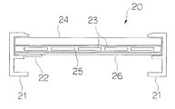
図17に示すように太陽光発電装置に用いられる太陽電池モジュール20は、シリコン等から成る太陽電池素子23の光電変換効果を利用して電力が得られるように構成したものであって、このような太陽電池素子23を複数個直列および並列に電気的に接続し、そして、耐候性のある素材で覆うように成し、所要の出力電圧や出力電流を得るようにしている。
As shown in FIG. 17, the
この太陽電池素子23は単結晶や多結晶シリコンなどの結晶系太陽電池や、薄膜系太陽電池などにより構成する。
This
かかる太陽電池モジュール20においては、太陽電池素子23の受光面にはガラス板や合成樹脂板などの光透過板24を配置し、その裏面である非受光面にはテフロン(登録商標)フィルムやPVF(ポリフッ化ビニル)、PET(ポリエチレンテレフタレート)などの耐候性フィルム26を被着し、光透過板24と耐候性フィルム26との間には、たとえばEVA(エチレン−酢酸ビニル共重合樹脂)などから成る透明な合成樹脂を介在し、充填材25と成し、これら光透過板24、太陽電池素子23および耐候性フィルム26の重ね構造の矩形状の本体に対し、その各辺周囲をアルミニウム金属やSUS等から成る枠体21を挟み込むように装着し、これにより、太陽電池部全体の強度を高めるとともに、枠体21に取付用の穴を開けて支持金具13にボルトやねじで固定できるようにしている。そして耐候性フィルム面上に設けられたジャンクションボックス22を介して太陽電池モジュール20の発電電力を取り出すことができるようにしている。
In the
この架台を介した太陽電池モジュールの固定方法は、剛性を非常に高くすることができ、暴風や積雪などの大きな外力に対する耐力があり、大規模な太陽光発電装置を構築するのに適している。 This method of fixing the solar cell module via the gantry can make the rigidity extremely high, has resistance against large external forces such as storms and snow, and is suitable for constructing a large-scale photovoltaic power generation apparatus. .
ところで、このような太陽光発電装置では発電効率を高めるために太陽電池モジュールを傾斜させて架台に設置する場合がほとんどであるが、このような場合の多くは図18のように太陽電池モジュール20と架台の支持金具13をボルト・ナットなどの締結部材12を用いて強固に固定・拘束してしまうことから、設置後の太陽電池モジュール傾斜角度の調整や、保守・点検作業が容易には行えないという問題点がある。
By the way, in such a solar power generation apparatus, in most cases, the solar cell module is inclined and installed on the pedestal in order to increase the power generation efficiency. In many cases, the
そこで、太陽電池モジュール周縁部に1ヶ所、回動機構をもたせて、保守・点検時の作業性を向上させる構造が提案されている(特許文献1を参照)。 Thus, a structure has been proposed in which a rotating mechanism is provided at the periphery of the solar cell module to improve workability during maintenance and inspection (see Patent Document 1).
また、太陽電池モジュールの架台に回動軸を設け、日射角にあわせて太陽電池モジュール傾斜角度を調整できる構造が提案されている(特許文献2を参照)。
しかしながら、前述したように設置後の太陽電池モジュール傾斜角度の調整や、保守・点検作業が容易に行えないという問題点を解決すべく、太陽電池モジュール周縁部に1ヶ所、回動機構を持たせて保守・点検時の作業性を向上させる構造とすると、回動機構をもつ太陽電池モジュール架台は回動軸が太陽電池モジュール中央部か周縁部に1つのみ存在する構造であり、特許文献1にあるような中央部に1軸機構をもつ架台は太陽電池モジュールの軸周りのモーメントを摩擦力で拘束する方法であるので、梃子の原理により外周部にかかる外力に対して十分な固定には強力な固定構造が必要となるといった問題がある。さらに、太陽電池モジュールの傾斜角が大きい場合には暴風など強い外力をより受け易くなるので、風圧による外力を最小に抑えるべく太陽電池モジュール傾斜角度を水平位置に固定できるような手段が別途必要であった。すなわち、太陽電池モジュールと架台の支持金具をボルト・ナットなどの締結部材を用いて強固に固定・拘束することに較べても性能的に劣るものである。 However, as described above, in order to solve the problem that adjustment of the inclination angle of the solar cell module after installation and maintenance / inspection work cannot be easily performed, a rotating mechanism is provided at one place on the periphery of the solar cell module. Assuming that the workability at the time of maintenance / inspection is improved, a solar cell module mount having a rotation mechanism has a structure in which only one rotation axis exists at the center or peripheral portion of the solar cell module. Since the gantry with a single axis mechanism in the center is a method of restraining the moment around the axis of the solar cell module with frictional force, it is necessary to fix the external force applied to the outer periphery by the lever principle. There is a problem that a strong fixing structure is required. In addition, when the inclination angle of the solar cell module is large, it is easier to receive strong external forces such as storms. Therefore, a means for fixing the inclination angle of the solar cell module in a horizontal position is required to minimize the external force due to wind pressure. there were. That is, it is inferior in performance as compared to firmly fixing and restraining the solar cell module and the support bracket of the mount using fastening members such as bolts and nuts.
一方、特許文献2にあるような周縁部に1つの回動軸機構をもつ架台では、太陽電池モジュールの回動がその回動軸の周方向に限定されてしまうので、保守・点検などの際、作業手順が限定されるといった問題が生じる。さらに、回動機構と、太陽電池モジュールの回動しない側の辺を固定するための機構の2種類の構造を用いなければならず、部品の品種の増加と施工作業の複雑化を招くこととなっていた。
On the other hand, in a pedestal having one rotating shaft mechanism at the peripheral edge as described in
本発明の目的は、簡単な構造にて、設置工事の際の組立て工程数を減らし、製作コストや部品品種を低減し、これによって低コスト化を達成した太陽光発電装置を提供することにある。 An object of the present invention is to provide a photovoltaic power generation apparatus that has a simple structure, reduces the number of assembly steps during installation work, reduces manufacturing costs and parts types, and thereby achieves cost reduction. .
上記目的を達成すべく、本発明の太陽光発電装置は、太陽電池モジュールを架台上に着脱可能に設置する固定方法であって、太陽電池モジュールと、2本の柱状レールと、前記2本の柱状レールのそれぞれに取り付けられる固定部材とからなる太陽光発電システムであって、前記固定部材は太陽電池モジュールの対向する2辺に固定され、前記2本の柱状レールのうち一方の柱状レールに対して回動自在に固定されるとともに、他方の柱状レールに対して着脱自在に固定されることを特徴とする。 In order to achieve the above object, the photovoltaic power generation apparatus of the present invention is a fixing method in which a solar cell module is detachably installed on a gantry, and includes a solar cell module, two columnar rails, and the two A photovoltaic power generation system comprising a fixing member attached to each of the columnar rails, wherein the fixing member is fixed to two opposite sides of the solar cell module, and one of the two columnar rails is And is fixed to the other columnar rail so as to be detachable.
本発明の太陽光発電装置によれば、上述した構成にすることにより、太陽電池モジュールが前記2本の柱状レールのうちいずれか一方を軸として柱状レールの外周を回動可能にすることにより、施工・交換・メンテナンスが簡単で、脱落の危険の少ない太陽光発電装置とする。 According to the solar power generation device of the present invention, by adopting the above-described configuration, the solar cell module can rotate the outer periphery of the columnar rail around one of the two columnar rails as an axis, A solar power generation device that is easy to install, replace, and maintain and has a low risk of falling off.
また、前記柱状レールに複数の太陽電池モジュールを取り付けた太陽光発電装置とすることにより、メンテナンス性の向上、送電ケーブルの見えない外観の良いものとする。太陽電池モジュール裏面の保守・点検、あるいは太陽電池モジュールの取付け・取外し作業を簡単・迅速かつ省力に行うことが可能となる。 In addition, by using a solar power generation apparatus in which a plurality of solar cell modules are attached to the columnar rails, the maintainability is improved and the power cable is not visible. Maintenance / inspection of the back side of the solar cell module, or installation / removal work of the solar cell module can be performed easily, quickly and with labor saving.
また、片方の固定部材のみを柱状レールから取外した状態として太陽電池モジュールを持ち上げると、もう片方の柱状レールを回動の中心軸として太陽電池モジュールを回動させることができ、これにより太陽電池モジュールの裏側の保守・点検あるいは取外し作業を極めて簡単に行うことができる。 In addition, when the solar cell module is lifted with only one fixing member removed from the columnar rail, the solar cell module can be rotated with the other columnar rail as the central axis of rotation, whereby the solar cell module Maintenance / inspection or removal work on the back side of can be performed very easily.
しかも、2つの柱状レールのうち、どちらの柱状レールでも回動の中心軸として用いることができるので、作業者の意図する回動方向で作業を行うことができる。 In addition, since either of the two columnar rails can be used as the central axis of rotation, the work can be performed in the rotation direction intended by the operator.
また、太陽電池モジュールが多数密集して設置される太陽光発電システムとしても良好なメンテナンス性を失わず、しかも発電面積を最小限にすることができる。 In addition, a good maintainability is not lost as a photovoltaic power generation system in which a large number of solar cell modules are densely installed, and the power generation area can be minimized.
以下、本発明の太陽光発電装置の一実施形態について、模式的に示した図面に基づいて詳細に説明する。 Hereinafter, an embodiment of a solar power generation device of the present invention will be described in detail based on the drawings schematically shown.
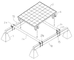
図1に示すように、本発明に係る太陽光発電装置Sは、太陽電池モジュール5と、2本の平行に設置された柱状レール3(3a、3b)と、固定部材4とで構成され、前記太陽電池モジュール5の下部に取り付けられた固定部材4が柱状レール3に巻きつくように固定されて成る。
As shown in FIG. 1, the photovoltaic power generation apparatus S according to the present invention includes a
固定部材4や柱状レール3は、例えば、アルミニウム金属やSUS、銅金属、真鍮などの金属や、ポリカーボネイト、FRP、カーボンなどの樹脂でも良く、特に柱状レール3は長さを延ばしてもたわみの発生が少ないものほど好適である。なお、本例では柱状レール3に円柱状のアルミレールを用いたが、後述するような角柱状レールを用いることもできる。また、図中では前記柱状レール3は、地上や屋根上などに設置された基礎レール1に固定バンド2などで取り付けるが、基礎レール1の代わりにコンクリートなどで造られた基礎ブロックに取り付けるのでも良く、目的に応じて取り付け対象を変更できる。
The
太陽電池モジュール5は一般に用いられる汎用型のものが使用可能であり、固定部材4を外枠材にネジや接着材で取り付ける。また、図中では固定部材4を太陽電池モジュール5の裏面に配するようにしているが側面に配置するものとしても良い。
The
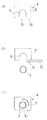
図2に固定部材の構成を示す。固定部材4は太陽電池モジュール5に取り付けて支持する支持部8と、柱状レールを挿入するとともに前記太陽電池モジュール5の位置出しをする軸溝部9と、前記軸溝部9から柱状レールが抜け出さないように軸溝部9の開口部分の蓋をするロック部材10とから構成される。ロック部材10は図中では支持部材8の下部にネジで水平方向に回転可能な構造を例としたが、後述する図7のような開閉機構を用いるようにすれば施工作業がより容易と出来る。
FIG. 2 shows the configuration of the fixing member. The fixing
具体的に、陸屋根上に置いた基礎ブロック間に基台レールを渡した架台上に、本発明に係る太陽光発電装置を配した実施形態について、模式的に示した図に基づき詳細に述べる。 Specifically, an embodiment in which a solar power generation device according to the present invention is arranged on a gantry in which base rails are passed between foundation blocks placed on a flat roof will be described in detail based on the schematic diagram.
図3に示すように、住宅の陸屋根上に基礎ブロック6を配置あるいはアンカーボルト等で屋根面に固定する。その上に基礎レール1(1a、1b)をボルトなどで固定し、基礎レール1(1a、1b)に円柱状のアルミニウム製丸パイプである2本の柱状レール3(3a、3b)を装着させるための固定バンド2(2a、2b)を前記柱状レールが平行に設置されるように配置する。このとき、図中のように固定バンド2b側にスペーサー15を噛ませて固定バンド2a側との間に高低差を生じさせることにより太陽電池モジュール5に傾斜角を持たせる事ができるので、固定バンド2a−2b間の距離は傾斜角に合わせて算出しておく。そして前記固定バンドに2本の柱状レール3(3a、3b)を乗せ、外れないように締め付け固定する。
As shown in FIG. 3, the
ところで、太陽電池モジュール5の裏側には固定部材4を取り付けるが、図15に示すようなバネ機構を有した開閉機構とすると良い。これは柱状レールを固定部材4の軸溝部9内に挿入していくときにはロック部材10が破線のように外側へ開いて道を譲り、柱状レールが所定の位置に達するまで挿入されるとバネBの復元力によってロック部材10が初期の位置に戻って支持部材8の開口部分を塞ぐようになることで柱状レールの抜け止めとなるものである。この開閉機構では、固定部材4のつまみ部Aを内側(矢印方向)に絞ることで、容易にロック機構が解除され太陽電池モジュールを架台から外すことができるので太陽電池モジュールのメンテナンス時などに作業性が良い。
By the way, although the fixing
そして、前述の固定部材4が付いた太陽電池モジュール5を2本の柱状レール3a、3bに上から乗せ、固定部材4のロック機構か作動する位置まで押しこむことで、図4のように架台上に太陽電池モジュール5が固定される。
Then, the
一方、固定部材4のロックを解除した状態で前述太陽電池モジュール5を上方向に移動させれば、前述太陽電池モジュール5を柱状レール3から容易に取外し可能であるが、図5に示すように、片方の固定部材4bのみを柱状レール3bから取外した状態として太陽電池モジュール5を持ち上げると、もう片方の柱状レール3aを回動の中心軸として太陽電池モジュール5を回動させることができる。これにより、太陽電池モジュールの裏側の保守・点検あるいは取外し作業を極めて簡単に行うことができる。
On the other hand, if the
しかも、再度両方の固定部材4(4a、4b)を柱状レール3(3a、3b)に固定した後に、今度は固定部材4aを柱状レール3aから取り外した状態とすれば、図6に示すように、柱状レール3bを回動の中心軸として太陽電池モジュール5を回動させることができるようになり、太陽電池モジュールの設置状況や作業のし易さによって回動方向を選択する事が可能である。
Moreover, after fixing both the fixing members 4 (4a, 4b) to the columnar rails 3 (3a, 3b) again, this time, if the fixing
次に、前述したような柱状レールと固定部材の回動の動作について詳細に説明する。なお、動作を判り易くするため図1の事例を用いるものとする。 Next, the rotation operation of the columnar rail and the fixing member as described above will be described in detail. In order to make the operation easy to understand, the example of FIG. 1 is used.
図7(a)に示すように、固定部材4は支持部8と、軸溝部9と、ロック部材10とから成る。ロック部材10はネジやボルトなどの締結部材16によって支持部材8に取り付けられており、締結部材16を適度に緩めることにより図7(b)に示すように支持部材8の一部を開口させて軸溝部9を円柱形状である柱状レール3を挿入可能な状態にできる。そして図7(c)に示すように、軸溝部9を柱状レール3を挿入した後、再度ロック部材10で支持部材8の開口部を塞ぐことにより固定部材4は柱状レール3に固定され、外れることはない。しかも固定部材4は柱状レール3の外周に沿って図中矢印のように回動することができるので、柱状レール3を回動の中心軸として固定部材4上に取り付けられている太陽電池モジュールを回動させることができるのである。さらにはロック部材10の内側の柱状レール3と接触する部分に摩擦係数の大きい部材(例えばブレーキパッド)を介在させれば、回動時に適度な反力を生じさせるようになり、重量のある太陽電池モジュールなどを回動させて降ろす際の作業者の安全確保と、重量を支える負担を軽減させることができる。
As shown in FIG. 7A, the fixing
また、ロック部材をバネのように弾性変形部材とすることにより、回転モーメントを加えても容易に動かない強固な固定を行なう事ができる。 In addition, by using an elastically deformable member such as a spring as the lock member, it is possible to perform firm fixation that does not easily move even when a rotational moment is applied.
同様にして柱状レールに角柱状のレールを用いる場合も、図8(a)に示すように固定部材4を四角柱状レール33に取り付けて、図8(b)のように回動させることができる。また、本例は四角柱であるが五角柱、六角柱でも同様であり、四角柱では2つの頂点によって固定部材4を支持するので円柱のように1点で支持されるよりも安定度が向上する。ただし、多角柱であるほど円柱形状のようなスムーズな滑りとできる。
Similarly, when a prismatic rail is used as the columnar rail, the fixing
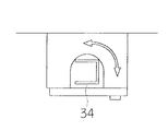
また、円柱状、多角柱状以外にも図9に示すようなコの字状レール34や、図10のようなI字状レールであっても同様の効果を得る事ができる。
Further, in addition to the columnar shape and the polygonal column shape, the same effect can be obtained with a
さらに、上述した角柱状レールにおいては回動の阻害とならないように、軸溝部とロック部材の空間は柱状レールの対角線の長さとするため柱状レールとロック部材の間には隙間が生じており、太陽電池モジュールなどの載置物の自重で固定されるだけであるが、ロック部材31をバネのように弾性変形部材とすることにより、強固な固定を行なう事ができる。具体的には、図11(a)に示すように、四角柱状レール33に固定部材4を取り付けた状態では、ロック部材31によって四角柱状レール33の底面33aが抑えられており、図中矢印のような回転モーメントを加えても固定部材4は外力に対して安定した状態で固定される。これによりメンテナンス時の一時固定などを可能として作業性を向上させることができる。
Furthermore, in order to prevent hindrance to rotation in the above-described prismatic rail, the space between the shaft groove and the lock member is the length of the diagonal line of the columnar rail, so that a gap is generated between the columnar rail and the lock member. Although it is only fixed by the dead weight of a mounted object such as a solar cell module, the
更に柱状レールを五角柱や六角柱としてロック部材で保持される角度を増やして脚部材の傾斜保持角度を選択できるようにすれば、太陽電池モジュールの傾斜角を変更可能とすることもできる。 Furthermore, the inclination angle of the solar cell module can be changed by increasing the angle at which the columnar rail is held by the lock member as a pentagonal column or hexagonal column so that the inclination holding angle of the leg member can be selected.
また、意図的に外力を一定以上に増した場合には、図11(b)に示すようにロック部材31が四角柱状レール33の角部33bに押されて変形し、四角柱状レール33の外周を固定部材4が回動可能となる。そして図11(c)のように90°回転すると四角柱状レール33の側部33cの位置でロック部材31が弾性変形して元の形状に戻る。ここで外力を弱めると再びロック部材31が固定部材4をその状態で固定しようとするので、固定部材4上の太陽電池モジュール5が直立状態で保持されるので、メンテナンス時の一時固定などに好適である。
In addition, when the external force is intentionally increased to a certain level or more, the
これを利用すれば、図12に示すように、脚部材7aと7bをそれぞれ異なる長さにして柱状レール3(3a、3b)に高低差が生じるように支持させることで、太陽電池モジュール5に傾斜角度を持たせ、特に図示しないが更に柱状レールを五角柱や六角柱としてロック部材で保持される角度を増やして脚部材7bの傾斜保持角度を選択できるようにすれば、太陽電池モジュール5の傾斜角を変更可能とすることもできる。このとき脚部材7a、7bの先端に基礎ブロック6を配しておけば風等による浮き上がりを防止できる。
If this is utilized, as shown in FIG. 12, the leg members 7a and 7b are made to have different lengths and are supported so that the height difference is generated in the columnar rails 3 (3a, 3b). If an inclination angle is provided and the angle at which the columnar rail is held by the lock member as a pentagonal column or a hexagonal column is increased, the inclination holding angle of the leg member 7b can be selected. The inclination angle can be changed. At this time, if the
以上詳述したように、2本の柱状レールに跨って、前記柱状レールの外周に沿って回動する固定部材を用いて太陽電池モジュールを設置する太陽光発電装置とすれば、様々な形状の柱状レールに設置が可能で、施工性、メンテナンス性が良い。また、傾斜角度を選択可能として発電効率の向上に寄与させることができる。 As described above in detail, if a solar power generation apparatus is used in which a solar cell module is installed using a fixing member that rotates along the outer periphery of the columnar rail across the two columnar rails, various shapes are provided. It can be installed on a columnar rail and has good workability and maintainability. In addition, the inclination angle can be selected to contribute to the improvement of power generation efficiency.
次に本発明に係る他の太陽光発電装置の実施形態について模式的な図を用いて説明する。 Next, an embodiment of another photovoltaic power generation apparatus according to the present invention will be described with reference to schematic drawings.
図13に示すように2本の柱状レール3(3a、3b)を縦方向に配して固定部材4で太陽電池モジュール5を固定するようにしても良い。この場合、例えば柱状レール3aを回動の中心軸として太陽電池モジュール5を回動させようとしたとき、脚部材7aと7bの高低差による傾斜角度が大きくなる(最大90°まで)ほど太陽電池モジュール5の回転時の重心点が柱状レール3aに移るので、作業者が太陽電池モジュール5を回動させるのに必要とする力を少なくすることができ、回動が容易となる。
As shown in FIG. 13, two columnar rails 3 (3 a, 3 b) may be arranged in the vertical direction and the
また、図14に示すように、2本の柱状レール3a、3b上に複数の太陽電池モジュール5a〜5cを配して太陽電池アレイ30とした太陽光発電装置とすることもできる。そして、このような太陽電池アレイを複数隣接して設置した場合でも容易にメンテナンスできる。例えば太陽電池モジュール5dが故障したとしたとき、太陽電池モジュール5bの位置にしか侵入通路がない設置状況(図示されていないだけで周囲にも太陽電池モジュールが設置されている等)であったとしても、まず太陽電池モジュール5bを太陽電池モジュール5e側に回動させて開き、次に太陽電池モジュール5aを外側に回動させて開けば、周囲の太陽電池モジュールを順次取り外すことなく容易に太陽電池モジュール5dにたどり着くことができる。このように太陽電池モジュールが多数密集して設置される太陽光発電装置においては、発電面積を最小にして、かつ、メンテナンス性を失わないという効果が大きい。
Moreover, as shown in FIG. 14, it can also be set as the solar power generation device which has arrange | positioned several solar cell module 5a-5c on the two
なお、本例も含め太陽光発電装置の発電出力は、図中の送電ケーブル17a、17bのように柱状レール3bや3cの中、もしくはコの字状レールやI字状レールの凹部分に各太陽電池モジュールの送電ケーブルを格納するようにすれば、ケーブルなどの配線が外から見えず外観がよい。
In addition, the power generation output of the photovoltaic power generation apparatus including this example is in the
1、1a、1b:基礎レール
2、2a、2b:固定バンド
3、3a〜3d:柱状レール
4:固定部材
5、5a〜5f:太陽電池モジュール
6 :基礎ブロック
7a、7b:脚部材
8:支持部
9:軸溝部
10:ロック部材
11:基礎
12:締結部材
13:支持金具
14:基台レール
15:スペーサー
16:締結部材
17a、17b:送電ケーブル
20:太陽電池モジュール
21:枠体
23:太陽電池素子
24:光透過板
25:充填材
26:耐候性フィルム
30:太陽電池アレイ
31:ロック部材
33:四角柱状レール
33a:底面
33b:角部
33c:側部
34:コの字状レール
35:I字状レール
J:太陽光発電装置
S:太陽光発電装置
A:つまみ部分
B:バネ
DESCRIPTION OF
Claims (2)
前記固定部材は太陽電池モジュールの対向する2辺に固定され、前記2本の柱状レールのうち一方の柱状レールに対して回動自在に固定されるとともに、他方の柱状レールに対して着脱自在に固定されることを特徴とする太陽光発電装置。 A photovoltaic power generation system comprising a solar cell module, two columnar rails, and a fixing member attached to each of the two columnar rails,
The fixing member is fixed to two opposite sides of the solar cell module, and is fixed to be rotatable with respect to one of the two columnar rails, and is detachable with respect to the other columnar rail. A solar power generation device characterized by being fixed.
Priority Applications (1)
| Application Number | Priority Date | Filing Date | Title |
|---|---|---|---|
| JP2005095843A JP2006278738A (en) | 2005-03-29 | 2005-03-29 | Photovoltaic power generating apparatus |
Applications Claiming Priority (1)
| Application Number | Priority Date | Filing Date | Title |
|---|---|---|---|
| JP2005095843A JP2006278738A (en) | 2005-03-29 | 2005-03-29 | Photovoltaic power generating apparatus |
Publications (1)
| Publication Number | Publication Date |
|---|---|
| JP2006278738A true JP2006278738A (en) | 2006-10-12 |
Family
ID=37213181
Family Applications (1)
| Application Number | Title | Priority Date | Filing Date |
|---|---|---|---|
| JP2005095843A Pending JP2006278738A (en) | 2005-03-29 | 2005-03-29 | Photovoltaic power generating apparatus |
Country Status (1)
| Country | Link |
|---|---|
| JP (1) | JP2006278738A (en) |
Cited By (30)
| Publication number | Priority date | Publication date | Assignee | Title |
|---|---|---|---|---|
| FR2922365A1 (en) * | 2007-10-16 | 2009-04-17 | Avancis Gmbh & Co Kg | IMPROVEMENTS TO ELEMENTS CAPABLE OF COLLECTING LIGHT. |
| FR2931181A1 (en) * | 2008-05-19 | 2009-11-20 | Clipsol Sa | Semi-rigid chassis structure for assembling modular photovoltaic solar sensors on frame of roof of building, has tabs located under sensors to hook sensors directly on purlins, and swing bar whose rigidity compensates flexibility of sensors |
| FR2934623A1 (en) * | 2008-07-30 | 2010-02-05 | Dani Alu | Photovoltaic solar panel assembly for balustrade device in building, has photovoltaic solar panel that is inclined with respect to vertical plane while being fixed on all or portion of straight lower part of post of balustrade device |
| EP2003406A3 (en) * | 2007-06-15 | 2010-04-07 | Phoenix Solar Aktiengesellschaft | Carrier assembly for a solar array, solar array with a number of solar modules and solar module for this purpose |
| FR2937353A1 (en) * | 2008-10-16 | 2010-04-23 | Regantox Sa | Photovoltaic covering element i.e. photovoltaic panel, installing device for flat roof, has connection devices that are detachable from one of sides of panels such that panels occupy horizontal usage position and vertical raised position |
| JP2012104786A (en) * | 2010-11-06 | 2012-05-31 | Yuushirou Kubo | Photovoltaic power generation module installation structure |
| JP5004259B1 (en) * | 2012-03-29 | 2012-08-22 | 株式会社共立 | Solar panel mount and installation method thereof |
| JP2012237165A (en) * | 2011-05-13 | 2012-12-06 | Sekisui Chem Co Ltd | Solar cell module fixing device |
| CN102870231A (en) * | 2010-05-03 | 2013-01-09 | 太阳能公司 | Methods and apparatuses to support photovoltaic modules |
| ITBO20110501A1 (en) * | 2011-08-25 | 2013-02-26 | Assea Srl | FLEXIBLE PHOTOVOLTAIC MODULE FOR MOUNTING ON ARCHED TUBULARS WITH INTEGRATED FIXING SYSTEM IN 3 POINTS |
| WO2013081050A1 (en) * | 2011-12-02 | 2013-06-06 | グリーンテック株式会社 | Mount support structure for solar cell module |
| JP2013524044A (en) * | 2010-03-26 | 2013-06-17 | サンパワー コーポレイション | Solar cell assembly secured on a sloping roof with minimal penetration and associated method |
| JP2013122127A (en) * | 2011-12-09 | 2013-06-20 | Aaki Yamade Kk | Solar panel fixing structure |
| JP2013204331A (en) * | 2012-03-29 | 2013-10-07 | Nippon Steel & Sumikin Metal Products Co Ltd | Solar panel installation structure and solar panel installation construction method |
| WO2014020006A1 (en) * | 2012-08-02 | 2014-02-06 | Hilti Aktiengesellschaft | Fastening element for mounting solar modules or solar collectors on a roof, and pitched roof having a fastening element |
| JP2014072636A (en) * | 2012-09-28 | 2014-04-21 | Softbank Mobile Corp | Antenna mounting frame assembly kit and base station |
| JP2014140302A (en) * | 2014-03-31 | 2014-07-31 | Office If Kk | Solar power generating apparatus and triangular metal fitting for inclination angle setting |
| JP2014139380A (en) * | 2013-01-21 | 2014-07-31 | Toyota Home Kk | Maintenance method for waterproof sheet, and frame for solar battery panel |
| JP2014152554A (en) * | 2013-02-12 | 2014-08-25 | Gantan Beauty Ind Co Ltd | Inclined mounting structure of solar battery panel |
| JP2015521457A (en) * | 2012-05-03 | 2015-07-27 | 常州天合光能有限公司 | Mounting structure of folding photovoltaic power generation assembly and mounting method thereof |
| KR200480266Y1 (en) | 2009-08-25 | 2016-05-02 | 쌩-고벵 글래스 프랑스 | System for mounting photovoltaic modules |
| WO2016102452A1 (en) * | 2014-12-22 | 2016-06-30 | Petrus Paulus Carolus Maria Stassen | A roof or wall covering system, a panel and method for installing panels |
| WO2016185555A1 (en) * | 2015-05-19 | 2016-11-24 | 不二精工株式会社 | Solar panel rack |
| US20170294867A1 (en) * | 2016-04-06 | 2017-10-12 | Solarcity Corporation | Spring latch saddle connector for solar tracker |
| JP2018011484A (en) * | 2016-07-15 | 2018-01-18 | シャープ株式会社 | Installation structure and maintenance method for photovoltaic power generation system |
| US10469024B2 (en) | 2016-04-08 | 2019-11-05 | Solarcity Corporation | Pre-assembled nesting photovoltaic module bracket for solar tracker |
| CN110645531A (en) * | 2019-08-22 | 2020-01-03 | 上海拾玖度文化传播有限责任公司 | Solar dancing lamp |
| US10587216B2 (en) | 2016-04-20 | 2020-03-10 | Solarcity Corporation | Over-center under photovoltaic module clamp |
| US11190129B2 (en) * | 2016-04-06 | 2021-11-30 | Tesla, Inc. | Photovoltaic module connector for solar tracker |
| CN117277928A (en) * | 2023-10-07 | 2023-12-22 | 惠州市创舰实业有限公司 | Quick mounting structure of photovoltaic energy storage |
-
2005
- 2005-03-29 JP JP2005095843A patent/JP2006278738A/en active Pending
Cited By (42)
| Publication number | Priority date | Publication date | Assignee | Title |
|---|---|---|---|---|
| EP2003406A3 (en) * | 2007-06-15 | 2010-04-07 | Phoenix Solar Aktiengesellschaft | Carrier assembly for a solar array, solar array with a number of solar modules and solar module for this purpose |
| FR2922366A1 (en) * | 2007-10-16 | 2009-04-17 | Avancis Gmbh & Co Kg | IMPROVEMENTS ON ELEMENTS CAPABLE OF COLLECTING LIGHT |
| WO2009050144A1 (en) * | 2007-10-16 | 2009-04-23 | Avancis Gmbh & Co. Kg | Improvements to light-collecting elements |
| FR2922365A1 (en) * | 2007-10-16 | 2009-04-17 | Avancis Gmbh & Co Kg | IMPROVEMENTS TO ELEMENTS CAPABLE OF COLLECTING LIGHT. |
| US9097442B2 (en) | 2007-10-16 | 2015-08-04 | Saint-Gobain Glass France | Made to elements capable of collecting light |
| FR2931181A1 (en) * | 2008-05-19 | 2009-11-20 | Clipsol Sa | Semi-rigid chassis structure for assembling modular photovoltaic solar sensors on frame of roof of building, has tabs located under sensors to hook sensors directly on purlins, and swing bar whose rigidity compensates flexibility of sensors |
| FR2934623A1 (en) * | 2008-07-30 | 2010-02-05 | Dani Alu | Photovoltaic solar panel assembly for balustrade device in building, has photovoltaic solar panel that is inclined with respect to vertical plane while being fixed on all or portion of straight lower part of post of balustrade device |
| FR2937353A1 (en) * | 2008-10-16 | 2010-04-23 | Regantox Sa | Photovoltaic covering element i.e. photovoltaic panel, installing device for flat roof, has connection devices that are detachable from one of sides of panels such that panels occupy horizontal usage position and vertical raised position |
| KR200480266Y1 (en) | 2009-08-25 | 2016-05-02 | 쌩-고벵 글래스 프랑스 | System for mounting photovoltaic modules |
| KR200480406Y1 (en) | 2009-08-25 | 2016-05-20 | 쌩-고벵 글래스 프랑스 | Fixing device and method for mounting solar modules |
| JP2013524044A (en) * | 2010-03-26 | 2013-06-17 | サンパワー コーポレイション | Solar cell assembly secured on a sloping roof with minimal penetration and associated method |
| CN102870231A (en) * | 2010-05-03 | 2013-01-09 | 太阳能公司 | Methods and apparatuses to support photovoltaic modules |
| JP2013527991A (en) * | 2010-05-03 | 2013-07-04 | サンパワー コーポレイション | Method and apparatus for supporting photovoltaic module |
| US9743501B2 (en) | 2010-05-03 | 2017-08-22 | Sunpower Corporation | Apparatuses to support photovoltaic modules |
| JP2012104786A (en) * | 2010-11-06 | 2012-05-31 | Yuushirou Kubo | Photovoltaic power generation module installation structure |
| JP2012237165A (en) * | 2011-05-13 | 2012-12-06 | Sekisui Chem Co Ltd | Solar cell module fixing device |
| ITBO20110501A1 (en) * | 2011-08-25 | 2013-02-26 | Assea Srl | FLEXIBLE PHOTOVOLTAIC MODULE FOR MOUNTING ON ARCHED TUBULARS WITH INTEGRATED FIXING SYSTEM IN 3 POINTS |
| WO2013081050A1 (en) * | 2011-12-02 | 2013-06-06 | グリーンテック株式会社 | Mount support structure for solar cell module |
| JP2013118236A (en) * | 2011-12-02 | 2013-06-13 | Greentec Kk | Cradle support structure for solar cell module |
| JP2013122127A (en) * | 2011-12-09 | 2013-06-20 | Aaki Yamade Kk | Solar panel fixing structure |
| JP2013204331A (en) * | 2012-03-29 | 2013-10-07 | Nippon Steel & Sumikin Metal Products Co Ltd | Solar panel installation structure and solar panel installation construction method |
| JP5004259B1 (en) * | 2012-03-29 | 2012-08-22 | 株式会社共立 | Solar panel mount and installation method thereof |
| US9559633B2 (en) | 2012-05-03 | 2017-01-31 | Changzhou Trina Solar Energy Co., Ltd. | Folded photovoltaic assembly mounting structure and mounting method therefor |
| JP2015521457A (en) * | 2012-05-03 | 2015-07-27 | 常州天合光能有限公司 | Mounting structure of folding photovoltaic power generation assembly and mounting method thereof |
| WO2014020006A1 (en) * | 2012-08-02 | 2014-02-06 | Hilti Aktiengesellschaft | Fastening element for mounting solar modules or solar collectors on a roof, and pitched roof having a fastening element |
| JP2014072636A (en) * | 2012-09-28 | 2014-04-21 | Softbank Mobile Corp | Antenna mounting frame assembly kit and base station |
| JP2014139380A (en) * | 2013-01-21 | 2014-07-31 | Toyota Home Kk | Maintenance method for waterproof sheet, and frame for solar battery panel |
| JP2014152554A (en) * | 2013-02-12 | 2014-08-25 | Gantan Beauty Ind Co Ltd | Inclined mounting structure of solar battery panel |
| JP2014140302A (en) * | 2014-03-31 | 2014-07-31 | Office If Kk | Solar power generating apparatus and triangular metal fitting for inclination angle setting |
| WO2016102452A1 (en) * | 2014-12-22 | 2016-06-30 | Petrus Paulus Carolus Maria Stassen | A roof or wall covering system, a panel and method for installing panels |
| NL1041128B1 (en) * | 2014-12-22 | 2016-10-11 | Ing Petrus Paulus Carolus Maria Stassen | A roof or wall covering system, a panel and method for installing panels. |
| WO2016185555A1 (en) * | 2015-05-19 | 2016-11-24 | 不二精工株式会社 | Solar panel rack |
| JPWO2016185555A1 (en) * | 2015-05-19 | 2018-03-08 | 不二精工株式会社 | Solar panel mount |
| US10367446B2 (en) | 2015-05-19 | 2019-07-30 | Fuji Seiko Co., Ltd. | Mount for solar panel |
| US20170294867A1 (en) * | 2016-04-06 | 2017-10-12 | Solarcity Corporation | Spring latch saddle connector for solar tracker |
| US10622937B2 (en) * | 2016-04-06 | 2020-04-14 | Solarcity Corporation | Spring latch saddle connector for solar tracker |
| US11190129B2 (en) * | 2016-04-06 | 2021-11-30 | Tesla, Inc. | Photovoltaic module connector for solar tracker |
| US10469024B2 (en) | 2016-04-08 | 2019-11-05 | Solarcity Corporation | Pre-assembled nesting photovoltaic module bracket for solar tracker |
| US10587216B2 (en) | 2016-04-20 | 2020-03-10 | Solarcity Corporation | Over-center under photovoltaic module clamp |
| JP2018011484A (en) * | 2016-07-15 | 2018-01-18 | シャープ株式会社 | Installation structure and maintenance method for photovoltaic power generation system |
| CN110645531A (en) * | 2019-08-22 | 2020-01-03 | 上海拾玖度文化传播有限责任公司 | Solar dancing lamp |
| CN117277928A (en) * | 2023-10-07 | 2023-12-22 | 惠州市创舰实业有限公司 | Quick mounting structure of photovoltaic energy storage |
Similar Documents
| Publication | Publication Date | Title |
|---|---|---|
| JP2006278738A (en) | Photovoltaic power generating apparatus | |
| US6563040B2 (en) | Structure for supporting a photovoltaic module in a solar energy collection system | |
| US9819302B2 (en) | Module attachment apparatus and method | |
| US9157664B2 (en) | Support structure and systems including the same | |
| US9117951B2 (en) | Solar cell module support structure | |
| US20100263659A9 (en) | Solar tracker system and method of making | |
| US20110290306A1 (en) | Solar array configurations | |
| JP2006210613A (en) | Solar power generator | |
| US20110197418A1 (en) | String Solar Panel Mounting System | |
| US20110290305A1 (en) | Cabled matrix for cantilevered photovoltaic solar panel arrays, apparatus and deployment systems | |
| JP2003184235A (en) | Supporting structure for solar cell module | |
| JP2004211372A (en) | Installation structure of solar panel | |
| JP2003234492A (en) | Fixture and technique of solar battery module | |
| JP2005317588A (en) | Photovoltaic power generating apparatus | |
| KR20100096641A (en) | Do damage from wind prevention apparatus for solar photovoltaics generator having a tilt | |
| JP2001152619A (en) | Support structure of solar-cell panel | |
| KR100882192B1 (en) | The sun rays tracking for the energy production ofelectric power system | |
| US20220149774A1 (en) | Rocking solar panel sun tracking mounting system | |
| JP4078399B2 (en) | Installation structure of solar cell module | |
| JP2002076411A (en) | Photovoltaic power generator | |
| KR20120003883U (en) | A fixing structure for frame of solar cell and post | |
| JP2001090274A (en) | Mounting structure of solar-cell module | |
| JP3178584U (en) | Solar panel mounting device | |
| KR101554483B1 (en) | Angle variable Solar generator having a Fixing device for controlling height | |
| JP2006118149A (en) | Photovoltaic power generating device and assembly thereof |