JP5902536B2 - Vehicle lighting - Google Patents
Vehicle lighting Download PDFInfo
- Publication number
- JP5902536B2 JP5902536B2 JP2012081902A JP2012081902A JP5902536B2 JP 5902536 B2 JP5902536 B2 JP 5902536B2 JP 2012081902 A JP2012081902 A JP 2012081902A JP 2012081902 A JP2012081902 A JP 2012081902A JP 5902536 B2 JP5902536 B2 JP 5902536B2
- Authority
- JP
- Japan
- Prior art keywords
- led light
- vehicle
- light source
- substrate
- light sources
- Prior art date
- Legal status (The legal status is an assumption and is not a legal conclusion. Google has not performed a legal analysis and makes no representation as to the accuracy of the status listed.)
- Active
Links
Images


Classifications
-
- B—PERFORMING OPERATIONS; TRANSPORTING
- B62—LAND VEHICLES FOR TRAVELLING OTHERWISE THAN ON RAILS
- B62J—CYCLE SADDLES OR SEATS; AUXILIARY DEVICES OR ACCESSORIES SPECIALLY ADAPTED TO CYCLES AND NOT OTHERWISE PROVIDED FOR, e.g. ARTICLE CARRIERS OR CYCLE PROTECTORS
- B62J6/00—Arrangement of optical signalling or lighting devices on cycles; Mounting or supporting thereof; Circuits therefor
- B62J6/04—Rear lights
-
- B—PERFORMING OPERATIONS; TRANSPORTING
- B60—VEHICLES IN GENERAL
- B60Q—ARRANGEMENT OF SIGNALLING OR LIGHTING DEVICES, THE MOUNTING OR SUPPORTING THEREOF OR CIRCUITS THEREFOR, FOR VEHICLES IN GENERAL
- B60Q1/00—Arrangement of optical signalling or lighting devices, the mounting or supporting thereof or circuits therefor
- B60Q1/0029—Spatial arrangement
- B60Q1/0041—Spatial arrangement of several lamps in relation to each other
-
- F—MECHANICAL ENGINEERING; LIGHTING; HEATING; WEAPONS; BLASTING
- F21—LIGHTING
- F21S—NON-PORTABLE LIGHTING DEVICES; SYSTEMS THEREOF; VEHICLE LIGHTING DEVICES SPECIALLY ADAPTED FOR VEHICLE EXTERIORS
- F21S41/00—Illuminating devices specially adapted for vehicle exteriors, e.g. headlamps
- F21S41/10—Illuminating devices specially adapted for vehicle exteriors, e.g. headlamps characterised by the light source
- F21S41/14—Illuminating devices specially adapted for vehicle exteriors, e.g. headlamps characterised by the light source characterised by the type of light source
- F21S41/141—Light emitting diodes [LED]
- F21S41/147—Light emitting diodes [LED] the main emission direction of the LED being angled to the optical axis of the illuminating device
- F21S41/148—Light emitting diodes [LED] the main emission direction of the LED being angled to the optical axis of the illuminating device the main emission direction of the LED being perpendicular to the optical axis
-
- F—MECHANICAL ENGINEERING; LIGHTING; HEATING; WEAPONS; BLASTING
- F21—LIGHTING
- F21S—NON-PORTABLE LIGHTING DEVICES; SYSTEMS THEREOF; VEHICLE LIGHTING DEVICES SPECIALLY ADAPTED FOR VEHICLE EXTERIORS
- F21S41/00—Illuminating devices specially adapted for vehicle exteriors, e.g. headlamps
- F21S41/10—Illuminating devices specially adapted for vehicle exteriors, e.g. headlamps characterised by the light source
- F21S41/14—Illuminating devices specially adapted for vehicle exteriors, e.g. headlamps characterised by the light source characterised by the type of light source
- F21S41/141—Light emitting diodes [LED]
- F21S41/151—Light emitting diodes [LED] arranged in one or more lines
-
- F—MECHANICAL ENGINEERING; LIGHTING; HEATING; WEAPONS; BLASTING
- F21—LIGHTING
- F21S—NON-PORTABLE LIGHTING DEVICES; SYSTEMS THEREOF; VEHICLE LIGHTING DEVICES SPECIALLY ADAPTED FOR VEHICLE EXTERIORS
- F21S41/00—Illuminating devices specially adapted for vehicle exteriors, e.g. headlamps
- F21S41/10—Illuminating devices specially adapted for vehicle exteriors, e.g. headlamps characterised by the light source
- F21S41/19—Attachment of light sources or lamp holders
-
- F—MECHANICAL ENGINEERING; LIGHTING; HEATING; WEAPONS; BLASTING
- F21—LIGHTING
- F21S—NON-PORTABLE LIGHTING DEVICES; SYSTEMS THEREOF; VEHICLE LIGHTING DEVICES SPECIALLY ADAPTED FOR VEHICLE EXTERIORS
- F21S41/00—Illuminating devices specially adapted for vehicle exteriors, e.g. headlamps
- F21S41/30—Illuminating devices specially adapted for vehicle exteriors, e.g. headlamps characterised by reflectors
- F21S41/32—Optical layout thereof
- F21S41/33—Multi-surface reflectors, e.g. reflectors with facets or reflectors with portions of different curvature
- F21S41/334—Multi-surface reflectors, e.g. reflectors with facets or reflectors with portions of different curvature the reflector consisting of patch like sectors
- F21S41/336—Multi-surface reflectors, e.g. reflectors with facets or reflectors with portions of different curvature the reflector consisting of patch like sectors with discontinuity at the junction between adjacent areas
-
- F—MECHANICAL ENGINEERING; LIGHTING; HEATING; WEAPONS; BLASTING
- F21—LIGHTING
- F21S—NON-PORTABLE LIGHTING DEVICES; SYSTEMS THEREOF; VEHICLE LIGHTING DEVICES SPECIALLY ADAPTED FOR VEHICLE EXTERIORS
- F21S41/00—Illuminating devices specially adapted for vehicle exteriors, e.g. headlamps
- F21S41/30—Illuminating devices specially adapted for vehicle exteriors, e.g. headlamps characterised by reflectors
- F21S41/39—Attachment thereof
-
- F—MECHANICAL ENGINEERING; LIGHTING; HEATING; WEAPONS; BLASTING
- F21—LIGHTING
- F21V—FUNCTIONAL FEATURES OR DETAILS OF LIGHTING DEVICES OR SYSTEMS THEREOF; STRUCTURAL COMBINATIONS OF LIGHTING DEVICES WITH OTHER ARTICLES, NOT OTHERWISE PROVIDED FOR
- F21V17/00—Fastening of component parts of lighting devices, e.g. shades, globes, refractors, reflectors, filters, screens, grids or protective cages
- F21V17/02—Fastening of component parts of lighting devices, e.g. shades, globes, refractors, reflectors, filters, screens, grids or protective cages with provision for adjustment
-
- F—MECHANICAL ENGINEERING; LIGHTING; HEATING; WEAPONS; BLASTING
- F21—LIGHTING
- F21V—FUNCTIONAL FEATURES OR DETAILS OF LIGHTING DEVICES OR SYSTEMS THEREOF; STRUCTURAL COMBINATIONS OF LIGHTING DEVICES WITH OTHER ARTICLES, NOT OTHERWISE PROVIDED FOR
- F21V7/00—Reflectors for light sources
Description
本発明は、車両用灯火器に関する。 The present invention relates to a vehicular lamp.
近年、自動二輪車等の車両のデザインは多様化しており、それに伴い、車両用灯火器の形状も様々なものがある。例えば、特許文献1には、テールライトの構造であって、ストップライト用LEDとテールライト用LEDとが水平な基板上で前後に離間して設けられており、これらのLEDの間をリフレクタで離隔する構造が記載されている。
In recent years, the design of vehicles such as motorcycles has been diversified, and accordingly, there are various shapes of vehicle lighting devices. For example,
ここで、車両用灯火器に求められるのは様々なデザインへの対応だけではなく、その一方で、車両の製造コスト低減の要望に応えることも求められる。しかし、特許文献1の構成のように従来の車両用灯火器では、LEDのポジションは予め決められているため、灯火器の形状が変わる場合に灯火器の形状に合わせたLEDの取付部を有する基板を設計しなくてはならず、製品の少量多品種化においては製造コスト増大の要因となる。
Here, the vehicle lighting equipment is required not only to cope with various designs but also to meet the demand for reducing the manufacturing cost of the vehicle. However, in the conventional vehicle lighting device as in the configuration of
そこで、本発明は、1つの基板で様々なデザインの車両用灯火器に対応させることを目的とする。 Therefore, an object of the present invention is to make it compatible with vehicle lighting devices of various designs with one substrate.
本発明によれば、LED光源と、前記LED光源が実装される取付部を有する基板と、前記LED光源を覆うように配置され、前記LED光源から出射された光を指向性を持って反射するリフレクタ部材と、を備えた車両用灯火器であって、前記取付部は、前記LED光源の配置を複数種類の配置の中から選択可能とするように、車両前後方向及び車両左右方向の少なくとも1方向において複数配置され、前記LEDの配置に応じた形状の前記リフレクタ部材を選択可能とするように、前記リフレクタ部材は、前記基板に脱着可能に装着され、前記リフレクタ部材は、前記LED光源から出射された光を指向性を持って反射する反射部と、前記基板に装着される装着部とを有し、前記装着部は、前記基板の表面を覆う第1壁部と、前記基板の裏面を覆う第2壁部と、前記基板の端面を覆う第3壁部と、を有し、前記第1乃至第3壁部により、前記基板が脱着可能に挿入される挿入部を形成し、前記1壁部及び前記第2壁部のうちの少なくともいずれか一方の壁部に、前記LED光源を露出させるための開口部を有し、前記開口部は、その一端が開放し、前記基板の挿入方向に延びるスリット状に形成されていることを特徴とする車両用灯火器が提供される。 According to the present invention, the LED light source, the substrate having the mounting portion on which the LED light source is mounted, and the LED light source are disposed so as to cover and reflect the light emitted from the LED light source with directivity. A vehicle lighting device including a reflector member, wherein the mounting portion is configured to select at least one of a vehicle front-rear direction and a vehicle left-right direction so that the arrangement of the LED light sources can be selected from a plurality of types of arrangements. The reflector member is detachably attached to the substrate, and the reflector member emits from the LED light source so that a plurality of the reflector members having a shape corresponding to the LED arrangement can be selected. A reflective portion that reflects the emitted light with directivity and a mounting portion that is mounted on the substrate, the mounting portion including a first wall that covers a surface of the substrate, A second wall portion covering the surface and a third wall portion covering the end surface of the substrate, and the first to third wall portions form an insertion portion into which the substrate is detachably inserted, At least one of the first wall portion and the second wall portion has an opening for exposing the LED light source, and one end of the opening is open, There is provided a vehicular lamp characterized by being formed in a slit shape extending in the insertion direction .
この車両用灯火器では、1種類の基板で複数のLEDポジションをレイアウトすることができ、その位置に合わせたリフレクタ部材を脱着可能に装着できる。そのため、灯火器の形状毎に基板を設計する必要がなく、同一の基板で複数の灯火器形状に対応したLED配置が可能となる。特に、カウル付き自動二輪車のヘッドライトのように、前傾(スラント)が強いヘッドライトにおいて、スペースが小さくデザインを多様に創作する場合にあっては特に好適である。また、基板の実装面を覆うことで、その保護や外観性の向上を図れ、簡易な構成で基板とりフレクタ部材の脱着を可能とし、基板端面等を覆うことによって外観性が向上する。 In this vehicle lighting device, a plurality of LED positions can be laid out on one type of board, and a reflector member that matches the position can be detachably mounted. Therefore, there is no need to design a substrate for each shape of the lighting device, and an LED arrangement corresponding to a plurality of lighting device shapes can be made on the same substrate. In particular, in a headlight having a strong forward tilt (slant), such as a headlight of a motorcycle with a cowl, it is particularly suitable when the space is small and various designs are created. Further, by covering the mounting surface of the substrate, the protection and appearance can be improved, and the reflector member can be attached and detached with a simple configuration, and the appearance is improved by covering the substrate end surface and the like.
また、本発明においては、前記取付部は、少なくとも前記車両左右方向に複数配置されると共に、前記基板には前記車両左右方向に複数の前記LED光源が実装され、前記リフレクタ部材は、前記LED光源から出射された光を指向性を持って反射する反射部を各々の前記LED光源に対応するように複数有し、各々の前記反射部は、対応する前記LED光源を囲むように湾曲した曲面を有してもよい。この構成の場合、各LED光源の目的方向への指向性を向上できる。 In the present invention, a plurality of the mounting portions are arranged at least in the left-right direction of the vehicle, a plurality of the LED light sources are mounted on the board in the left-right direction of the vehicle, and the reflector member is the LED light source. A plurality of reflecting portions that reflect the light emitted from each of the LED light sources in a directional manner, and each of the reflecting portions has a curved surface that is curved so as to surround the corresponding LED light source. You may have. In the case of this configuration, the directivity of each LED light source in the target direction can be improved.
また、本発明によれば、LED光源と、前記LED光源が実装される取付部を有する基板と、前記LED光源を覆うように配置され、前記LED光源から出射された光を指向性を持って反射するリフレクタ部材と、を備えた車両用灯火器であって、前記取付部は、前記LED光源の配置を複数種類の配置の中から選択可能とするように、車両前後方向及び車両左右方向の少なくとも1方向において複数配置され、前記LEDの配置に応じた形状の前記リフレクタ部材を選択可能とするように、前記リフレクタ部材は、前記基板に脱着可能に装着され、前記取付部は、前記車両前後方向及び前記車両左右方向に複数配置されると共に、前記基板には前記車両左右方向に複数の前記LED光源が実装され、前記リフレクタ部材は、前記LED光源から出射された光を指向性を持って反射する反射部を各々の前記LED光源に対応するように複数有し、前記LED光源の少なくとも1つは、他の前記LED光源に対して前記車両前後方向にずれて配置され、前記LED光源の配置に対応させるように、前記反射部の少なくとも1つは、他の前記反射部に対して前記車両前後方向にずれて配置されることを特徴とする車両用灯火器が提供される。この車両用灯火器では、1種類の基板で複数のLEDポジションをレイアウトすることができ、その位置に合わせたリフレクタ部材を脱着可能に装着できる。そのため、灯火器の形状毎に基板を設計する必要がなく、同一の基板で複数の灯火器形状に対応したLED配置が可能となる。特に、カウル付き自動二輪車のヘッドライトのように、前傾(スラント)が強いヘッドライトにおいて、スペースが小さくデザインを多様に創作する場合にあっては特に好適である。また、凹凸のあるデザインにも対応できる。 According to the present invention , the LED light source, the substrate having the mounting portion on which the LED light source is mounted, and the LED light source are arranged so as to cover the light emitted from the LED light source with directivity. And a reflector member for reflecting, wherein the mounting portion is arranged in the vehicle front-rear direction and the vehicle left-right direction so that the arrangement of the LED light sources can be selected from a plurality of types of arrangements. The reflector member is detachably attached to the substrate so that the reflector member having a plurality of arrangements in at least one direction and having a shape corresponding to the arrangement of the LEDs can be selected. A plurality of LED light sources are mounted on the board in the vehicle left-right direction, and the reflector member includes the LED light sources. A plurality of reflecting portions that reflect the emitted light with directivity so as to correspond to each of the LED light sources, and at least one of the LED light sources is in front of and behind the other LED light sources. are arranged offset in the direction so as to correspond to the arrangement of the LED light source, at least one of said reflecting section is characterized Rukoto disposed offset in the vehicle longitudinal direction with respect to the other of said reflective portion A vehicle lighting device is provided . In this vehicle lighting device, a plurality of LED positions can be laid out on one type of board, and a reflector member that matches the position can be detachably mounted. Therefore, there is no need to design a substrate for each shape of the lighting device, and an LED arrangement corresponding to a plurality of lighting device shapes can be made on the same substrate. In particular, in a headlight having a strong forward tilt (slant), such as a headlight of a motorcycle with a cowl, it is particularly suitable when the space is small and various designs are created. It can also handle uneven designs.
また、本発明によれば、LED光源と、前記LED光源が実装される取付部を有する基板と、前記LED光源を覆うように配置され、前記LED光源から出射された光を指向性を持って反射するリフレクタ部材と、を備えた車両用灯火器であって、前記取付部は、前記LED光源の配置を複数種類の配置の中から選択可能とするように、車両前後方向及び車両左右方向の少なくとも1方向において複数配置され、前記LEDの配置に応じた形状の前記リフレクタ部材を選択可能とするように、前記リフレクタ部材は、前記基板に脱着可能に装着され、前記取付部は、前記車両前後方向及び前記車両左右方向に複数配置されると共に、前記基板には前記車両左右方向に複数の前記LED光源が実装され、前記リフレクタ部材は、前記LED光源から出射された光を指向性を持って反射する反射部を各々の前記LED光源に対応するように複数有し、前記車両左右方向の中央側の前記LED光源は、前記車両左右方向の両端側の前記LED光源よりも前記車両前後方向のうち一方向側にずれて配置され、前記LED光源の配置に対応させるように、前記車両左右方向の中央側の前記反射部は、前記車両左右方向の両端側の前記反射部よりも前記車両前後方向のうち一方向側にずれて配置されることを特徴とする車両用灯火器が提供される。この車両用灯火器では、1種類の基板で複数のLEDポジションをレイアウトすることができ、その位置に合わせたリフレクタ部材を脱着可能に装着できる。そのため、灯火器の形状毎に基板を設計する必要がなく、同一の基板で複数の灯火器形状に対応したLED配置が可能となる。特に、カウル付き自動二輪車のヘッドライトのように、前傾(スラント)が強いヘッドライトにおいて、スペースが小さくデザインを多様に創作する場合にあっては特に好適である。また、中心側が凹んだ灯火器のデザインに対応できる。 According to the present invention , the LED light source, the substrate having the mounting portion on which the LED light source is mounted, and the LED light source are arranged so as to cover the light emitted from the LED light source with directivity. And a reflector member for reflecting, wherein the mounting portion is arranged in the vehicle front-rear direction and the vehicle left-right direction so that the arrangement of the LED light sources can be selected from a plurality of types of arrangements. The reflector member is detachably attached to the substrate so that the reflector member having a plurality of arrangements in at least one direction and having a shape corresponding to the arrangement of the LEDs can be selected. A plurality of LED light sources are mounted on the board in the vehicle left-right direction, and the reflector member includes the LED light sources. The LED light sources on the center side in the vehicle left-right direction are both end sides in the vehicle left-right direction. The LED light source is arranged so as to be shifted to one direction side in the vehicle front-rear direction, and the reflecting portion on the center side in the vehicle left-right direction is arranged in the vehicle left-right direction so as to correspond to the arrangement of the LED light sources. the vehicle lighting apparatus according to claim Rukoto of the reflecting portion of the both end sides are arranged offset in one direction side of the vehicle longitudinal direction is provided. In this vehicle lighting device, a plurality of LED positions can be laid out on one type of board, and a reflector member that matches the position can be detachably mounted. Therefore, there is no need to design a substrate for each shape of the lighting device, and an LED arrangement corresponding to a plurality of lighting device shapes can be made on the same substrate. In particular, in a headlight having a strong forward tilt (slant), such as a headlight of a motorcycle with a cowl, it is particularly suitable when the space is small and various designs are created. In addition, it is possible to cope with the design of a lamp with a recessed center.
本発明によれば、1つの基板で様々なデザインの車両用灯火器に対応させることができる。 According to the present invention, a single board can be used for various types of vehicle lighting devices.
以下、本発明の実施形態に係る車両用灯火器を自動二輪車に適用した場合について説明するが、本発明は自動四輪車等、他の車両にも適用可能である。なお、各図において矢印x、yは互いに直交する水平方向、矢印z方向は上下方向を示し、x方向は車両前後方向を、y方向は車両左右方向を、z方向は車両上下方向を示している。 Hereinafter, although the case where the vehicle lighting device which concerns on embodiment of this invention is applied to a motorcycle is demonstrated, this invention is applicable also to other vehicles, such as a four-wheeled vehicle. In each figure, arrows x and y indicate horizontal directions orthogonal to each other, arrow z direction indicates the vertical direction, x direction indicates the vehicle longitudinal direction, y direction indicates the vehicle lateral direction, and z direction indicates the vehicle vertical direction. Yes.
<第1実施形態>
<自動二輪車の全体構成>
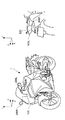
図1は、自動二輪車1の外観図である。図1に示すように、自動二輪車1は車両前部に本発明の一実施形態に係る車両用灯火器であるヘッドライトユニット100を備える。また、他の灯火器として、サイドミラー前面にフロントウインカ200L、200R、車両後方(本実施形態ではテールライト500の両側部、図中右側の後方視参照)にリアウインカ400L、400R、及び車両後部にテールライト500(図中右側の後方視参照)を備える。本実施形態では、ヘッドライトユニット100に本発明を適用した場合を例示するが、テールライト500等、他の部位の灯火器にも本発明は適用可能である。
<First Embodiment>
<Overall configuration of motorcycle>
FIG. 1 is an external view of the
<ヘッドライトユニットの概略>
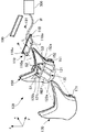
図2はヘッドライトユニット100の組立図である。以下、ヘッドライトユニット100の構成について、図2を参照して概説する。
<Outline of headlight unit>
FIG. 2 is an assembly diagram of the
ヘッドライトユニット100は、複数のLED光源Lが実装された基板110と、リフレクタ部材120と、ハウジング150と、レンズ部材170と、を備える。本実施形態の場合、リフレクタ部材120はハウジング150と別部材とされて互いに固定されているが、両者は一体的に形成してもよい。
The
本実施形態の場合、リフレクタ部材120は装着部121と、反射部REFと、上下の壁面122aと、左右の壁面122bとを有しており、基板110は装着部121に対してその後方側から脱着可能に装着される。そして、基板110の後端部に固定された取付部材118の穴118a及びハウジング150のボス152に設けられた穴152aに係止具181をはめ込むことにより基板110がハウジング150に固定される。
In the case of the present embodiment, the
さらに、基板110の後方を覆うカバー190がハウジング150の後方からハウジング150に取り付けられると共に、ハウジング150の前方からレンズ部材170が取り付けられる。
Further, a
レンズ部材170は、ポリカーボネート等の透明樹脂で爪171を有する。そして、ハウジング150に設けた係合穴151に爪171を係合することで、レンズ部材170がハウジング150に固定される。このとき、レンズ部材170とハウジング150との間には図4(b)及び図4(c)に示されるようなシール材153が設けられている。シール材153は、ヘッドライトユニット100内部への水滴等の侵入を防止する。LED光源L等から出射された光はリフレクタ部材120の反射部REFによって指向性を持って反射され、レンズ部材170を通って自動二輪車1の前方を照明する。基板110には配線Wを介してコントローラ300が電気的に接続され、電力が供給される。
The
<基板の構成>
図3を参照して基板110の構成について詳細に説明する。図3(a)は基板110の平面図、図3(b)は基板110の底面図である。本実施形態では、ヘッドライトユニット100を自動二輪車1に組み付けた状態において、基板110が水平姿勢となる場合を想定している。
<Board configuration>
The configuration of the
基板110は全体として板状をなしており、組み付け状態で上面となる表面110aと、下面となる裏面110bとを有する。本実施形態の場合、基板110が両面基板である場合を想定しており、表面110a及び裏面110bは共にLED光源Lの実装面を構成している。しかし、片面のみが実装面であってもよい。
The board |
本実施形態では、LED光源Lとして合計6つのLED光源Lが基板110に実装される場合を想定しており、個々のLED光源を区別する場合は、LED光源L1〜L6と表記する。
In the present embodiment, it is assumed that a total of six LED light sources L are mounted on the
基板110は、LED光源Lを実装するための取付部を基板の表面110a及び裏面110bにそれぞれ有している。
The board |
詳細には、表面110aには合計9つの取付部111a1〜111a3、111b1〜111b3、111c1〜111c3(以下、総称するときは取付部111という。)が設けられている。また、裏面110bには合計9つの取付部112a1〜112a3、112b1〜112b3、112c1〜112c3(以下、総称するときは取付部112という。)が設けられている。
Specifically, nine attachment portions 111a1 to 111a3, 111b1 to 111b3, and 111c1 to 111c3 (hereinafter collectively referred to as attachment portions 111) are provided on the
各取付部111、112は、LED光源Lが電気的に接続される電極を少なくとも備えていればよい。そして、LED光源Lの実装を容易にするため、差し込みにより電気的な接続が可能なソケットであることが好ましい。 Each attachment part 111,112 should just be equipped with the electrode with which the LED light source L is electrically connected at least. And in order to make mounting of the LED light source L easy, it is preferable that it is a socket which can be electrically connected by insertion.
表面110aの取付部111は、車両前後方向に沿って複数配置(ここでは3箇所)されると共に、車両左右方向にも複数配置(3箇所)されている。取付部111の符号の添え字のうち、英字(a〜c)は車両左右方向の位置が同じである列を示し、数字(1〜3)は車両前後方向の位置が同じである行を示している。例えば、取付部111a1〜111a3は互いに車両前後方向の位置は異なるが、車両左右方向の位置は同じとなっている。また、取付部111a1、111b1、111c1は互いに車両左右方向の位置は異なるが、車両前後方向の位置は同じとなっている。こうして、表面110aの取付部111は、3×3のマトリックス状の配置となっている。
A plurality of mounting portions 111 on the
裏面110bの取付部112についても、表面110aの取付部111と同様に3×3のマトリックス状の配置となっており、取付部112の符号の添え字による列、行のルールも同じである。更に本実施形態では、添え字が同じ取付部111と取付部112とは、車両前後方向及び車両左右方向における位置は同じで、表裏の関係にある一つの対をなしている。例えば、表面110aの取付部111a1の裏側には、裏面110bの取付部112a1が位置している。
The attachment portion 112 on the
本実施形態では、表面110aに3個のLED光源L1〜L3が実装される場合を想定しており、特に、取付部111の各列に1つずつ実装する場合を想定している。図3(a)の例では、取付部111a1、111b3、111c1にそれぞれLED光源L1、L2、L3が実装された場合を例示しているが、LED光源L1〜L3は、3×3×3=27種類の配置の中からいずれかの配置を選択可能となっている。
In this embodiment, the case where the three LED light sources L1-L3 are mounted in the
また、裏面110bにも3個のLED光源L4〜L6が実装される場合を想定しおり、表面110aと同様に、取付部112の各列に1つずつ実装する場合を想定している。図3(b)の例では、取付部112a1、112b3、112c1にそれぞれLED光源L4、L5、L6が実装された場合を例示しているが、LED光源L4〜L6は、3×3×3=27種類の配置の中からいずれかの配置を選択可能となっている。
In addition, it is assumed that three LED light sources L4 to L6 are mounted on the
図3(a)、図3(b)とは異なる配置の例として、例えば、図7(a)、図7(b)に示すものがある。本例では、全てのLED光源L1〜L6は車両前後方向における位置を揃えるように、すなわち、横一線となるように最も前方の取付部111a1〜111c1、112a1〜112c1に実装されている。Examples of arrangements different from those shown in FIGS. 3A and 3B include those shown in FIGS. 7A and 7B, for example. In this example, all the LED light sources L1 to L6 are mounted on the foremost mounting portions 111a1 to 111c1 and 112a1 to 112c1 so as to align the positions in the vehicle front-rear direction, that is, in a horizontal line.
なお、本実施形態では、取付部111、112を車両前後方向及び車両左右方向の双方向について、複数配置したが、少なくともいずれか1方向において複数配置されていればよい。たとえば、車両左右方向にのみ複数配置してもよく、車両前後方向にのみ複数配置してもよい。また、一方向における取付部111、112の数も3つに限られず、2或いは4以上であってもよい。この数を増やす程、配置の種類が増えることはいうまでもない。 In the present embodiment, a plurality of mounting portions 111 and 112 are arranged in both the vehicle front-rear direction and the vehicle left-right direction, but a plurality of attachment portions 111 and 112 may be arranged in at least one direction. For example, a plurality may be arranged only in the vehicle left-right direction, or a plurality may be arranged only in the vehicle front-rear direction. Further, the number of attachment portions 111 and 112 in one direction is not limited to three, and may be two or four or more. It goes without saying that the number of types of arrangement increases as the number increases.
また、取付部111、112を車両前後方向及び車両左右方向の双方向に複数配置する場合であっても、必ずしも本実施形態のようにマトリックス状に配置しなくてもよい。但し、ランダムに配置するよりもマトリックス状に配置した方が、結果として配置の自由度が優れる場合がある。 Further, even when a plurality of mounting portions 111 and 112 are arranged in both the vehicle front-rear direction and the vehicle left-right direction, it is not always necessary to arrange them in a matrix as in the present embodiment. However, as a result, the degree of freedom of arrangement may be superior when arranged in a matrix rather than randomly.
更に、本実施形態では、取付部111と取付部112とが表裏の関係にある一つの対をなしているが、取付部111と取付部112とで配置がバラバラであってもよい。 Furthermore, in the present embodiment, the attachment portion 111 and the attachment portion 112 form one pair in a front-back relationship, but the arrangement between the attachment portion 111 and the attachment portion 112 may be different.
更に、取付部111、112の数とLED光源Lの数との関係も、本実施形態の関係(9対3)に限られず、取付部111、112の数がLED光源Lの数を少なくとも上回っていればよい。 Furthermore, the relationship between the number of attachment portions 111 and 112 and the number of LED light sources L is not limited to the relationship of this embodiment (9 to 3), and the number of attachment portions 111 and 112 exceeds the number of LED light sources L at least. It only has to be.
<リフレクタ部材の構成>
リフレクタ部材120について図4及び図5を参照して説明する。図4(a)は、基板110が装着されたリフレクタ部材120の正面図、図4(b)は図4(a)の線A−Aに沿う断面図、図4(c)は図4(a)の線B−Bに沿う断面図である。図5は基板110が装着されたリフレクタ部材120の斜視図である。なお、図5においては、説明する箇所を明瞭に図示するため、上下の壁面122aのうち、上側の図示を省略する。
<Structure of reflector member>
The
LED光源L1〜L6の配置は図3に示した配置としており、LED光源Lの配置に応じた形状のリフレクタ部材120が選択的に装着され、逆に言えば、リフレクタ部材120の形状に応じてLED光源Lの配置が選択される。
The LED light sources L1 to L6 are arranged as shown in FIG. 3, and the
リフレクタ部材120は、装着部121と、反射部REF(1〜6)と、上下の壁面122aと、左右の壁面122bとを有する。
The
装着部121は、基板110の表面110aを覆う上側の壁部121aと、裏面110bを覆う下側の壁部121bと、基板110の前端面を前側の壁部121cと、一対の側壁部121dと、を有し、後部が開放した箱型をなしている。そして、これらの壁部により、基板110が脱着可能に挿入される挿入部を形成している。このように本実施形態では簡易な構成で基板110とリフレクタ部材120の脱着を可能としている。
The mounting
装着部121には、スリット状の開口部S1〜S3が形成されている。開口部S1〜S3は壁部121a及び121bの双方に形成されており、かつ、取付部111、112の配置に対応して形成されている。図3も参照して説明すると、開口部S1は取付部111a1〜111a3の列及び取付部112a1〜112a3の列に対応する位置に形成されている。開口部S2は取付部111b1〜111b3の列及び取付部112b1〜112b3の列に対応する位置に形成されている。開口部S3は取付部111c1〜111c3の列及び取付部112b1〜112b3の列に対応する位置に形成されている。
In the mounting
上記の通り、本実施形態では、取付部111、112の各列に1つずつLED光源Lを実装する場合を想定している。このため、開口部S1〜S3もこの列に合わせて形成されている。したがって、基板110を装着した場合、LED光源L1〜L6を開口部S1〜S3を通して装着部121から露出することができる。
As described above, in this embodiment, it is assumed that one LED light source L is mounted in each row of the attachment portions 111 and 112. Therefore, the openings S1 to S3 are also formed in accordance with this row. Therefore, when the board |
なお、本実施形態では、組み付け性を考慮して、開口部S1〜S3を後方が開放された切り欠き状としている。しかし、開口部S1〜S3は周囲が閉じた穴状に形成されてもよい。但しこの場合、LED光源Lを、基板110を装着部121に装着した後に実装するか、装着部121の壁部121aと壁部121bとが分離可能な構成とする等の対策が必要とされる。
In the present embodiment, the openings S1 to S3 have a notch shape with the rear opened in consideration of assembly. However, the openings S1 to S3 may be formed in a hole shape with a closed periphery. However, in this case, it is necessary to take measures such as mounting the LED light source L after the
本実施形態では、壁部121a、121bが基板の表面110a及び裏面110bを、壁部121cが基板110の前方の端面を覆う構成であるため、基板110の大部分が外部に露出することがなく、したがって、ヘッドライトユニット100ひいては自動二輪車1の外観性が向上する。特に、基板110の前方の端面が露出していると、レンズ部材170を通して外部から視認されやすいが、壁部121cで隠されるので外観性の向上効果が高い。また、これらの壁部により基板110の保護も図れる。その上、壁部121a及び壁部121bが遮光性の材料であれば、目的とする方向以外に出射されるLED光源L1〜L6からの光が漏れることも防止可能である。
In the present embodiment, since the
反射部REF1〜REF6は、LED光源L1〜L6から出射された光を指向性を持って反射するよう、その内面が鏡面となっている。鏡面とするための処理としては、ABS樹脂の基材にメッキ処理をするものが代表的である。 The inner surfaces of the reflecting portions REF1 to REF6 are mirror surfaces so as to reflect the light emitted from the LED light sources L1 to L6 with directivity. A typical example of the treatment for forming a mirror surface is to plate the base material of the ABS resin.
本実施形態の場合、反射部REFは各々のLED光源Lに対応するように設けられており、本実施形態の場合、6つのLED光源L1〜L6が実装されるため、6つの反射部REF1〜REF6が設けられている。 In the case of this embodiment, the reflection part REF is provided so as to correspond to each LED light source L, and in the case of this embodiment, since six LED light sources L1 to L6 are mounted, six reflection parts REF1 to REF1 are provided. REF6 is provided.
各反射部REFは、LED光源Lの背後側から弧状に湾曲して前方へ延出している。 Each reflecting portion REF is curved in an arc from the back side of the LED light source L and extends forward.
表面110a側のLED光源L1〜L3に対応する反射部REF1〜REF3は、壁部121aから上方に延び、裏面110b側のLED光源L4〜6に対応する反射部REF4〜REF6は、壁部121bから下方に延びる。本実施形態では、このように、基板110の表面110a側と裏面110b側の両側にLED光源L1〜L6及び反射部REF1〜REF6を配置することにより、発光するLED光源Lを上下に切り替えることができ、例えばハイビーム(LED光源L4〜L6を発光)とロービーム(LED光源L1〜L3を発光)のように光を向ける方向を切り替えることができる。
Reflective portions REF1 to REF3 corresponding to the LED light sources L1 to L3 on the
本実施形態の場合、各反射部REF1〜6はLED光源Lの背後側から弧状に湾曲して前方へ延出しているだけでなく、対応するLED光源Lを囲むように左右方向に弧状に湾曲している。すなわち、xy平面及びxz平面の何れの平面に平行な断面においても反射部REF1〜REF6は湾曲している。これにより、各LED光源L1〜L6の目的方向への指向性を向上できる。 In the case of the present embodiment, each of the reflecting portions REF1 to REF6 is curved in an arc shape from the back side of the LED light source L and extends forward, and is also curved in an arc shape in the left-right direction so as to surround the corresponding LED light source L. doing. That is, the reflecting portions REF1 to REF6 are curved in a cross section parallel to any plane of the xy plane and the xz plane. Thereby, the directivity to the target direction of each LED light source L1-L6 can be improved.
<コントローラ>
図6は、自動二輪車1に搭載されるライト類の点灯を制御するコントローラ300周辺のブロック図である。コントローラ300はスイッチ類310に対する操作が検出されると、対応するライト類を点灯等する。
<Controller>
FIG. 6 is a block diagram around the
スイッチ類310としては、ヘッドライト用スイッチ311、ハイビームとロービームの切り替えスイッチ312、左右ウインカ用スイッチ313L、313R、ブレーキライト410(テールライト内に組み込まれる)を点灯させるブレーキレバー314等が含まれる。
The
コントローラ300は漏れ電流をカットする機能(リークカット機能)を有する制御回路で構成されることが好ましい。一般にLED光源は微小電流でも微発光する。そのため、漏れ電流によりLED光源が発光することがある。この場合リークカット回路を追加する対策が考えられるが、各LED光源にリークカット用の回路を設けるとコスト的に不利である。そこで、コントローラ300として、複数のLED光源のリークカット機能を有する制御回路を用いることで、複数のリークカット回路を追加することなくまとめてリークカットが可能となる。
The
また、本実施形態では、点灯、消灯が同期する左フロントウインカ200L及び左リアウインカ400Lや、右フロントウインカ200R及び右リアウインカ400Rに、それぞれ独立した出力ポートを割り当てている。これらはコントローラ300の出力ポートを兼用し、配線を途中でL側とR側に分岐させて接続する構成も採用可能である。しかし、配線分岐箇所に防水対策が必要とされるため、コントローラ300の出力ポートと、各ライト類の入力ポートに、個別に防水対策が既になされている製品を使用した上で、本実施形態のように、独立した出力ポートを割り当てる方が、配線分岐箇所の防水対策が不要となる点で有利である。
In the present embodiment, independent output ports are assigned to the left
<LED光源の配置とリフレクタ部材との組み合わせ例>
本実施形態の基板110は予めLED光源Lの取付部111、112を車両前後及び左右方向に複数持ち、これらの取付部111、112からLED光源Lの配置を選択できる。すなわち、1種類の基板110で複数のLEDポジションをレイアウトすることができる。
<Example of combination of LED light source arrangement and reflector member>
The
よって、LEDポジションに合わせたリフレクタ部材120を装着したり、逆に、リフレクタ部材120の形状に応じたLEDポジションを選択できる。そのため、灯火器の形状ごとに基板110を設計する必要がなく、同一の基板110で複数の灯火器形状に対応したLED配置が可能となり、様々なデザインの車両用灯火器に対応させることができる。
Therefore, the
以下、LED光源Lの配置とリフレクタ部材120の組合せの例について説明する。なお、以下の説明で参照する図のうち、斜視図(図9、図11、図13)においては、説明する箇所を明瞭に図示するため、上下の壁面122aのうち、上側の図示を省略する。
Hereinafter, an example of a combination of the arrangement of the LED light source L and the
<組合せ例1>
本例1は、既に説明した図3のLEDポジションと、図4及び図5のリフレクタ部材120との組合せ例である。
<Combination example 1>
The first example is a combination example of the already-described LED position of FIG. 3 and the
本例の場合、基板110の表面110a側に着目すると、左右方向両端側のLED光源L1、L3は最も前方の取付部111a1、111c1に、中央側のLED光源L2は最も後方の取付部111b3にそれぞれ実装されている。つまり、中央側のLED光源L2は他のLED光源L1、L3に対して車両前後方向にずれて配置されている。
In the case of this example, when focusing on the
これに対応してリフレクタ部材120の反射部REF1〜REF3も中央側の反射部REF2は他の反射部REF1、REF3に対して車両前後方向にずれて配置されている。
Correspondingly, the reflection parts REF1 to REF3 of the
本例は、LED光源Lの少なくとも1つ(L2)は、他のLED光源L(L1、L3)に対して車両前後方向にずれて配置され、LED光源Lの配置に対応させるように、反射部REFの少なくとも1つ(REF2)は、他の反射部REF(REF1、3)に対して車両前後方向にずれて配置された例である。この構成の場合、例えばレンズ部材170の一部が凹んでいる場合等、凹凸のあるデザインにも対応できる。特に、中央側のLED光源L2及び対応する反射部REF2が車両前後方向の一方向側(後方側)にずれているので、レンズ部材170の中央部分が凹んでいるデザインに対応可能である。
In this example, at least one of the LED light sources L (L2) is arranged so as to be shifted in the vehicle front-rear direction with respect to the other LED light sources L (L1, L3), and reflected so as to correspond to the arrangement of the LED light sources L. At least one of the parts REF (REF2) is an example in which the part REF is displaced in the vehicle front-rear direction with respect to the other reflection parts REF (REF1, 3). In the case of this configuration, for example, when the
なお、基板110の裏面110b側のLED光源L4〜L6及び対応するREF4〜REF6も表面110a側と同様の構成である。
Incidentally, REF4~REF6 also Ru configuration der the
<組合せ例2>
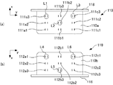
本例は、LEDポジションが図8に、基板110を装着したリフレクタ部材120が図9(a)にそれぞれ示されている。図8(a)は基板110の平面図、図8(b)は基板110の底面図である。
< Combination example 2 >
This example, LED positions in FIG. 8, the
図8を参照して、基板110の表面110a側に着目すると、本例では、LED光源L1〜L3が、全て、互いに車両前後方向にずれて配置されており、しかも、左右方向で順番にずれている。
Referring to FIG. 8 , focusing on the
これに対応してリフレクタ部材120の反射部REF1〜REF3も、図9(a)に示すように、反射部REF1〜REF3が、全て、互いに車両前後方向にずれて配置されており、しかも、左右方向で順番にずれている。
Reflecting portion REF1~REF3 of the
基板110の裏面110b側のLED光源L4〜L6及び対応するREF4〜REF6も表面110a側と同様の構成である。
The LED light sources L4 to L6 and the corresponding REF4 to REF6 on the
本例の場合、例えば、図9(b)に示すように、LED光源Lと反射部REFの配置を左右対称としたものとセットで用いることができ、一方を右用、他方を左用とすることができる。そして、流線形状の一つのレンズ部材170に2セット適用するか、或いは、レンズ部材170を右用、左用それぞれ用意して、両眼タイプとし、個々のレンズ部材170に1セットずつ適用することもできる。
In this example, for example, as shown in FIG. 9 (b), the arrangement of the LED light source L and the reflecting portion REF can be used in symmetric and the ones with the set, to the right one, the other as a left be able to. Then, two sets are applied to one
<組合せ例3>
本例は、LEDポジションが図10に、基板110を装着したリフレクタ部材120が図11にそれぞれ示されている。図10(a)は基板110の平面図、図10(b)は基板110の底面図である。
<Combination example 3 >
This example, LED positions in FIG. 10, the
図10に示すように、本例では、LED光源Lの配置が基板110の表面110a側と裏面110b側とで異なる。上記の通り、本実施形態では、取付部111と取付部112とが表裏の関係にある一つの対をなしており、これまでの例では、車両左右方向で同じとなる取付部111、112の対については、車両前後方向でも同じ位置にLED光源Lを実装している。例えば、図8の例でいえば、表面110a側のLED光源L1と、裏面101b側のLED光源L4とは、車両左右方向の位置が同じLED対をなしており、車両前後方向で見ても同じ位置(最後部)となっている。LED光源L2とLED光源L5のLED対、LED光源L3とLED光源L6のLED対も同様である。
As shown in FIG. 10 , in this example, the arrangement of the LED light sources L is different between the
一方、図10に示す本例の場合では、LED光源L1とL4のLED対では、LED光源L1が車両後方側の取付部111a3、LED光源L4が車両前方側の取付部112a1に実装される。すなわち、表面側のLED光源L1と裏面側のLED光源L4とが車両前後方向にずれて配置されている。 On the other hand, in the case of this example shown in FIG. 10 , in the LED pair of the LED light sources L1 and L4, the LED light source L1 is mounted on the mounting portion 111a3 on the vehicle rear side, and the LED light source L4 is mounted on the mounting portion 112a1 on the vehicle front side. That is, the LED light source L1 on the front surface side and the LED light source L4 on the back surface side are arranged to be shifted in the vehicle front-rear direction.
LED光源L2とL5のLED対では、LED光源L2が中間の取付部111b2、LED光源L5が車両後方側の取付部112b3に実装され、車両前後方向にずれている。LED光源L3とL6のLED対でも、LED光源L3が車両後方側の取付部111c3、LED光源L6が車両前方側の取付部111c1に実装され、車両前後方向にずれている。 In the LED pair of the LED light sources L2 and L5, the LED light source L2 is mounted on the middle mounting portion 111b2 and the LED light source L5 is mounted on the mounting portion 112b3 on the vehicle rear side, and is shifted in the vehicle front-rear direction. Even in the LED pair of the LED light sources L3 and L6, the LED light source L3 is mounted on the mounting portion 111c3 on the rear side of the vehicle, and the LED light source L6 is mounted on the mounting portion 111c1 on the front side of the vehicle.
このようなLEDポジションに対応して、図11に示すように反射部REF1〜REF6も配置されている。すなわち、表面110a側では、反射部REF1及びREF3は後方の位置、反射部REF2は中間の位置となっている。また、裏面110b側では、反射部REF4及びREF6は前方の位置、反射部REF6は後方の位置となっている。
In response to such LED positions are reflected portion REF1~REF6 be arranged as shown in FIG. 11. That is, on the
本例は、例えば車両上側と下側とで、透明部材170の形状が異なるようなデザインにおいて対応可能である。なお、ここでは、全てのLED対において表面側と裏面側のLED光源Lが車両前後方向にずれて実装されているが、一部のLED対のみがずれて配置されていてもよい。この場合も反射部REFの配置はLED光源Lの配置に対応したものとなる。
This example can be applied to a design in which the shape of the
<組合せ例4>
本例は、LEDポジションが図12に、基板110を装着したリフレクタ部材120が図13にそれぞれ示されている。図12(a)は基板110の平面図、図12(b)は基板110の底面図である。
<Combination example 4 >
This example, LED positions in FIG. 12, the
本例は車用左右方向の何れかの一端側にあるLED光源Lのみを車両前後方向にずらした例であり、図12の例では、LED光源L3、L6のみ他のLED光源Lに対して車両前後方向後方側に配置したものである。 This example is an example in which only the LED light source L on one end side in the left-right direction for the vehicle is shifted in the vehicle front-rear direction. In the example of FIG. 12 , only the LED light sources L3 and L6 are relative to the other LED light sources L. It is arranged on the rear side in the vehicle longitudinal direction.
対応するリフレクタ部材120の反射部REFの配置も図13に示すとおりであり、反射部REF3及びREF6のみ他の反射部REFに対して車両前後方向後方側に配置している。
The arrangement of the reflecting part REF of the
本例は、例えば、レンズ部材170の車両左右方向一端側が凹んでいるデザインに対応できる。
This example can correspond to, for example, a design in which one end of the
<第2実施形態>
上記第1実施形態では装着部121の後部を開放して基板110を装着部121の後部から脱着可能としたが、前部を開放して前部から基板110の脱着を行う構成としてもよい。
Second Embodiment
In the first embodiment, the rear portion of the mounting
図14は、基板110をハウジング150の前方から挿し込む構成例であるヘッドライトユニット100Aの組立図である。上記第1実施形態と同様の構成については同じ符号を付している。
FIG. 14 is an assembly diagram of a
本実施形態の場合、リフレクタ部材120の装着部121’は、その前部が開放して挿入部が開口し、その後部は閉鎖されている(不図示)。また、開口部S1〜S3は上記第1実施形態と異なり、前方が開放された切り欠き状としている。この構成は上記第1実施形態の構成と比較すると、LED光源Lの光が上記第1実施形態よりも後方に漏れ難く、前方に出射され易い場合がある。
In the case of the present embodiment, the mounting
本実施形態では、基板110の前側に取付部材118が位置しているが、挿入時の向きを変えるだけで上記第1実施形態の基板110をそのまま利用可能である。
In the present embodiment, the mounting
100 車両用灯火器(ヘッドライトユニット)
L1〜L6 LED光源
110 基板
120 リフレクタ部材
111、112 取付部
100 Vehicle lighting equipment (headlight unit)
L1 to L6
Claims (4)
前記LED光源が実装される取付部を有する基板と、
前記LED光源を覆うように配置され、前記LED光源から出射された光を指向性を持って反射するリフレクタ部材と、
を備えた車両用灯火器であって、
前記取付部は、前記LED光源の配置を複数種類の配置の中から選択可能とするように、車両前後方向及び車両左右方向の少なくとも1方向において複数配置され、
前記LEDの配置に応じた形状の前記リフレクタ部材を選択可能とするように、前記リフレクタ部材は、前記基板に脱着可能に装着され、
前記リフレクタ部材は、前記LED光源から出射された光を指向性を持って反射する反射部と、前記基板に装着される装着部とを有し、
前記装着部は、前記基板の表面を覆う第1壁部と、前記基板の裏面を覆う第2壁部と、前記基板の端面を覆う第3壁部と、を有し、
前記第1乃至第3壁部により、前記基板が脱着可能に挿入される挿入部を形成し、
前記1壁部及び前記第2壁部のうちの少なくともいずれか一方の壁部に、前記LED光源を露出させるための開口部を有し、
前記開口部は、その一端が開放し、前記基板の挿入方向に延びるスリット状に形成されている
ことを特徴とする車両用灯火器。 An LED light source;
A substrate having a mounting portion on which the LED light source is mounted;
A reflector member arranged to cover the LED light source and reflecting the light emitted from the LED light source with directivity;
A vehicle lighting device comprising:
A plurality of the mounting portions are arranged in at least one direction of the vehicle front-rear direction and the vehicle left-right direction so that the arrangement of the LED light sources can be selected from a plurality of types of arrangements,
The reflector member is detachably attached to the substrate so that the reflector member having a shape corresponding to the arrangement of the LEDs can be selected .
The reflector member has a reflecting portion that reflects light emitted from the LED light source with directivity, and a mounting portion that is mounted on the substrate,
The mounting portion includes a first wall portion covering the surface of the substrate, a second wall portion covering the back surface of the substrate, and a third wall portion covering the end surface of the substrate,
The first to third wall portions form an insertion portion into which the substrate is detachably inserted,
At least one of the first wall and the second wall has an opening for exposing the LED light source,
The vehicle lighting device according to claim 1, wherein one end of the opening is opened and formed in a slit shape extending in the insertion direction of the substrate .
前記基板には前記車両左右方向に複数の前記LED光源が実装され、
前記リフレクタ部材は、前記LED光源から出射された光を指向性を持って反射する反射部を各々の前記LED光源に対応するように複数有し、
各々の前記反射部は、対応する前記LED光源の左右方向を囲むように湾曲した曲面を有する
ことを特徴とする請求項1に記載の車両用灯火器。 A plurality of the mounting portions are arranged in at least the left-right direction of the vehicle,
A plurality of the LED light sources are mounted on the board in the vehicle left-right direction,
The reflector member has a plurality of reflecting portions that reflect the light emitted from the LED light sources with directivity so as to correspond to the LED light sources,
2. The vehicle lighting device according to claim 1, wherein each of the reflecting portions has a curved surface that is curved so as to surround a left-right direction of the corresponding LED light source.
前記LED光源が実装される取付部を有する基板と、
前記LED光源を覆うように配置され、前記LED光源から出射された光を指向性を持って反射するリフレクタ部材と、を備えた車両用灯火器であって、
前記取付部は、前記LED光源の配置を複数種類の配置の中から選択可能とするように、車両前後方向及び車両左右方向の少なくとも1方向において複数配置され、
前記LEDの配置に応じた形状の前記リフレクタ部材を選択可能とするように、前記リフレクタ部材は、前記基板に脱着可能に装着され、
前記取付部は、前記車両前後方向及び前記車両左右方向に複数配置されると共に、
前記基板には前記車両左右方向に複数の前記LED光源が実装され、
前記リフレクタ部材は、前記LED光源から出射された光を指向性を持って反射する反射部を各々の前記LED光源に対応するように複数有し、
前記LED光源の少なくとも1つは、他の前記LED光源に対して前記車両前後方向にずれて配置され、
前記LED光源の配置に対応させるように、前記反射部の少なくとも1つは、他の前記反射部に対して前記車両前後方向にずれて配置される
ことを特徴とする車両用灯火器。 An LED light source;
A substrate having a mounting portion on which the LED light source is mounted;
A vehicular lamp comprising: a reflector member arranged to cover the LED light source and reflecting the light emitted from the LED light source with directivity;
A plurality of the mounting portions are arranged in at least one direction of the vehicle front-rear direction and the vehicle left-right direction so that the arrangement of the LED light sources can be selected from a plurality of types of arrangements,
The reflector member is detachably attached to the substrate so that the reflector member having a shape corresponding to the arrangement of the LEDs can be selected.
A plurality of the mounting portions are arranged in the vehicle front-rear direction and the vehicle left-right direction,
A plurality of the LED light sources are mounted on the board in the vehicle left-right direction,
The reflector member has a plurality of reflecting portions that reflect the light emitted from the LED light sources with directivity so as to correspond to the LED light sources,
At least one of the LED light sources is arranged to be shifted in the vehicle front-rear direction with respect to the other LED light sources,
So as to correspond to the arrangement of the LED light source, at least one of said reflecting portion, car dual lighting system you being disposed offset in the vehicle longitudinal direction with respect to the other of said reflecting portion.
前記LED光源が実装される取付部を有する基板と、
前記LED光源を覆うように配置され、前記LED光源から出射された光を指向性を持って反射するリフレクタ部材と、を備えた車両用灯火器であって、
前記取付部は、前記LED光源の配置を複数種類の配置の中から選択可能とするように、車両前後方向及び車両左右方向の少なくとも1方向において複数配置され、
前記LEDの配置に応じた形状の前記リフレクタ部材を選択可能とするように、前記リフレクタ部材は、前記基板に脱着可能に装着され、
前記取付部は、前記車両前後方向及び前記車両左右方向に複数配置されると共に、
前記基板には前記車両左右方向に複数の前記LED光源が実装され、
前記リフレクタ部材は、前記LED光源から出射された光を指向性を持って反射する反射部を各々の前記LED光源に対応するように複数有し、
前記車両左右方向の中央側の前記LED光源は、前記車両左右方向の両端側の前記LED光源よりも前記車両前後方向のうち一方向側にずれて配置され、
前記LED光源の配置に対応させるように、前記車両左右方向の中央側の前記反射部は、前記車両左右方向の両端側の前記反射部よりも前記車両前後方向のうち一方向側にずれて配置される
ことを特徴とする車両用灯火器。 An LED light source;
A substrate having a mounting portion on which the LED light source is mounted;
A vehicular lamp comprising: a reflector member arranged to cover the LED light source and reflecting the light emitted from the LED light source with directivity;
A plurality of the mounting portions are arranged in at least one direction of the vehicle front-rear direction and the vehicle left-right direction so that the arrangement of the LED light sources can be selected from a plurality of types of arrangements,
The reflector member is detachably attached to the substrate so that the reflector member having a shape corresponding to the arrangement of the LEDs can be selected.
A plurality of the mounting portions are arranged in the vehicle front-rear direction and the vehicle left-right direction,
A plurality of the LED light sources are mounted on the board in the vehicle left-right direction,
The reflector member has a plurality of reflecting portions that reflect the light emitted from the LED light sources with directivity so as to correspond to the LED light sources,
The LED light source on the center side in the vehicle left-right direction is arranged to be shifted to one direction side in the vehicle front-rear direction from the LED light sources on both ends in the vehicle left-right direction,
In order to correspond to the arrangement of the LED light sources, the reflecting portion on the center side in the left-right direction of the vehicle is shifted to one direction side in the vehicle front-rear direction with respect to the reflecting portions on both ends in the left-right direction of the vehicle. car dual lighting apparatus characterized in that it is.
Priority Applications (5)
| Application Number | Priority Date | Filing Date | Title |
|---|---|---|---|
| JP2012081902A JP5902536B2 (en) | 2012-03-30 | 2012-03-30 | Vehicle lighting |
| IN1329CH2013 IN2013CH01329A (en) | 2012-03-30 | 2013-03-26 | |
| DE102013205317A DE102013205317A1 (en) | 2012-03-30 | 2013-03-26 | Lamp for a vehicle |
| CN201310103835.5A CN103359210B (en) | 2012-03-30 | 2013-03-28 | Car light |
| US13/852,658 US9056578B2 (en) | 2012-03-30 | 2013-03-28 | Lamp for vehicle |
Applications Claiming Priority (1)
| Application Number | Priority Date | Filing Date | Title |
|---|---|---|---|
| JP2012081902A JP5902536B2 (en) | 2012-03-30 | 2012-03-30 | Vehicle lighting |
Publications (2)
| Publication Number | Publication Date |
|---|---|
| JP2013211211A JP2013211211A (en) | 2013-10-10 |
| JP5902536B2 true JP5902536B2 (en) | 2016-04-13 |
Family
ID=49154978
Family Applications (1)
| Application Number | Title | Priority Date | Filing Date |
|---|---|---|---|
| JP2012081902A Active JP5902536B2 (en) | 2012-03-30 | 2012-03-30 | Vehicle lighting |
Country Status (5)
| Country | Link |
|---|---|
| US (1) | US9056578B2 (en) |
| JP (1) | JP5902536B2 (en) |
| CN (1) | CN103359210B (en) |
| DE (1) | DE102013205317A1 (en) |
| IN (1) | IN2013CH01329A (en) |
Families Citing this family (17)
| Publication number | Priority date | Publication date | Assignee | Title |
|---|---|---|---|---|
| CN104203736B (en) * | 2012-03-29 | 2016-08-24 | 本田技研工业株式会社 | The head lamp device of two-wheeled motor vehicle |
| FR3022977A1 (en) * | 2014-06-30 | 2016-01-01 | Valeo Vision | LOWER MASK OF OPTICAL MODULE OF MOTOR VEHICLE |
| JP6059277B2 (en) * | 2015-03-23 | 2017-01-11 | 本田技研工業株式会社 | Headlight device |
| JP2016181388A (en) * | 2015-03-24 | 2016-10-13 | スタンレー電気株式会社 | Lighting appliance of vehicle |
| JP6544963B2 (en) * | 2015-03-30 | 2019-07-17 | 本田技研工業株式会社 | Headlight |
| JP6712123B2 (en) * | 2015-06-29 | 2020-06-17 | 株式会社小糸製作所 | Vehicle lighting |
| CN107735615B (en) * | 2015-06-29 | 2021-02-09 | 株式会社小糸制作所 | Vehicle lamp |
| JP2017013712A (en) * | 2015-07-03 | 2017-01-19 | ヤマハ発動機株式会社 | Headlight |
| CN106364598B (en) * | 2015-07-24 | 2019-05-03 | 本田技研工业株式会社 | Direction of traffic instruction device |
| SI25030A (en) * | 2015-07-30 | 2017-01-31 | Hella Saturnus Slovenija Proizvodnja Svetlobne Opreme Za Motorna In Druga Vozila, D.O.O. | Multifunctional light of a motor vehicle |
| CN106369523A (en) * | 2016-10-31 | 2017-02-01 | 江门市鼎豪汽摩部件有限公司 | Motorcycle tail lamp structure adopting chip LEDs |
| CN108613116A (en) * | 2017-01-16 | 2018-10-02 | 常州星宇车灯股份有限公司 | Matrix LED front lamp device based on reflection |
| JP2018133164A (en) * | 2017-02-14 | 2018-08-23 | 株式会社小糸製作所 | Vehicular lighting fixture |
| JP2018166090A (en) * | 2017-03-28 | 2018-10-25 | 株式会社小糸製作所 | Vehicular lighting tool |
| FR3069819B1 (en) * | 2017-08-01 | 2019-09-20 | Psa Automobiles Sa | LIGHTING DEVICE CONFIGURABLE IN RELATION TO ITS LOCATION OF INSTALLATION IN A VEHICLE |
| JP6897404B2 (en) * | 2017-08-03 | 2021-06-30 | サクサ株式会社 | Lighting structure of electronic devices |
| JP2020098726A (en) * | 2018-12-18 | 2020-06-25 | スタンレー電気株式会社 | Saddle-type vehicle lighting appliance |
Family Cites Families (7)
| Publication number | Priority date | Publication date | Assignee | Title |
|---|---|---|---|---|
| JP2004221013A (en) * | 2003-01-17 | 2004-08-05 | Stanley Electric Co Ltd | Lighting fixture for vehicle |
| JP4339050B2 (en) * | 2003-09-04 | 2009-10-07 | 本田技研工業株式会社 | Motorcycle taillight device |
| WO2005028250A1 (en) * | 2003-09-22 | 2005-03-31 | Decoma International Inc. | Vehicular light assembly |
| ITMI20051492A1 (en) * | 2005-07-29 | 2007-01-30 | Ecie S R L | LED LIGHTING DEVICE WITH ORTHOGONAL OPTICAL AXIS TO THE OPTICAL AXIS OF THE SAME DEVICE |
| JP4996951B2 (en) | 2007-03-23 | 2012-08-08 | 本田技研工業株式会社 | Tail lamp structure |
| JP5150336B2 (en) * | 2008-03-28 | 2013-02-20 | スタンレー電気株式会社 | LED lamp |
| JP5077274B2 (en) * | 2009-03-24 | 2012-11-21 | 豊田合成株式会社 | Vehicle headlamp |
-
2012
- 2012-03-30 JP JP2012081902A patent/JP5902536B2/en active Active
-
2013
- 2013-03-26 IN IN1329CH2013 patent/IN2013CH01329A/en unknown
- 2013-03-26 DE DE102013205317A patent/DE102013205317A1/en not_active Withdrawn
- 2013-03-28 CN CN201310103835.5A patent/CN103359210B/en active Active
- 2013-03-28 US US13/852,658 patent/US9056578B2/en active Active
Also Published As
| Publication number | Publication date |
|---|---|
| US9056578B2 (en) | 2015-06-16 |
| DE102013205317A1 (en) | 2013-10-02 |
| JP2013211211A (en) | 2013-10-10 |
| CN103359210B (en) | 2016-03-09 |
| US20130286674A1 (en) | 2013-10-31 |
| IN2013CH01329A (en) | 2015-08-21 |
| CN103359210A (en) | 2013-10-23 |
Similar Documents
| Publication | Publication Date | Title |
|---|---|---|
| JP5902536B2 (en) | Vehicle lighting | |
| US9328889B2 (en) | Vehicle lighting unit | |
| US9995451B2 (en) | Lighting device with a light conductor for a motor vehicle exterior lighting system | |
| US20060239024A1 (en) | Headlamp with beam patterns formed from semiconductor light sources | |
| US20070012550A1 (en) | Modular operating switch assembly | |
| US20070081350A1 (en) | Rearview mirror and signal light arrangement | |
| KR20140054251A (en) | Lighting device for a motor vehicle | |
| JP2013073687A (en) | Vehicular lamp fitting | |
| CN105508958A (en) | Automotive Light | |
| JP2007294459A (en) | Lighting or signalling device with depth effect | |
| JP2006310108A (en) | Signal lamp for vehicle | |
| US8052312B2 (en) | Vehicle lighting device | |
| US8777467B2 (en) | Vehicle interior lighting system | |
| US11204147B1 (en) | Headlight unit having micro-light emitting diode device, relay lens system and projection lens system | |
| US20180195682A1 (en) | Vehicle lighting assembly | |
| JP7172283B2 (en) | vehicle lamp | |
| JP6599467B2 (en) | Switch device | |
| JP4666174B2 (en) | Vehicle lighting | |
| KR20170046205A (en) | Light source module of led head lamp for vehicle | |
| JP6734084B2 (en) | Traffic light and its color unit | |
| JP6324017B2 (en) | Vehicle lamp | |
| JP2011258528A (en) | Warning lamp | |
| EP3772447B1 (en) | Steering light assembly | |
| CN210740292U (en) | Signal lamp with light channeling prevention structure | |
| JP5988150B2 (en) | Vehicle lighting device |
Legal Events
| Date | Code | Title | Description |
|---|---|---|---|
| A621 | Written request for application examination |
Free format text: JAPANESE INTERMEDIATE CODE: A621 Effective date: 20141127 |
|
| A977 | Report on retrieval |
Free format text: JAPANESE INTERMEDIATE CODE: A971007 Effective date: 20150817 |
|
| A131 | Notification of reasons for refusal |
Free format text: JAPANESE INTERMEDIATE CODE: A131 Effective date: 20150824 |
|
| A521 | Request for written amendment filed |
Free format text: JAPANESE INTERMEDIATE CODE: A523 Effective date: 20151013 |
|
| TRDD | Decision of grant or rejection written | ||
| A01 | Written decision to grant a patent or to grant a registration (utility model) |
Free format text: JAPANESE INTERMEDIATE CODE: A01 Effective date: 20160219 |
|
| A61 | First payment of annual fees (during grant procedure) |
Free format text: JAPANESE INTERMEDIATE CODE: A61 Effective date: 20160310 |
|
| R150 | Certificate of patent or registration of utility model |
Ref document number: 5902536 Country of ref document: JP Free format text: JAPANESE INTERMEDIATE CODE: R150 |