JP5901034B1 - Game machine - Google Patents
Game machine Download PDFInfo
- Publication number
- JP5901034B1 JP5901034B1 JP2014218977A JP2014218977A JP5901034B1 JP 5901034 B1 JP5901034 B1 JP 5901034B1 JP 2014218977 A JP2014218977 A JP 2014218977A JP 2014218977 A JP2014218977 A JP 2014218977A JP 5901034 B1 JP5901034 B1 JP 5901034B1
- Authority
- JP
- Japan
- Prior art keywords
- data
- medal
- game
- winning
- bell
- Prior art date
- Legal status (The legal status is an assumption and is not a legal conclusion. Google has not performed a legal analysis and makes no representation as to the accuracy of the status listed.)
- Active
Links
- 238000000034 method Methods 0.000 claims abstract description 1054
- 230000008569 process Effects 0.000 claims abstract description 1046
- 238000012545 processing Methods 0.000 claims abstract description 302
- 238000013500 data storage Methods 0.000 claims abstract description 44
- 238000011084 recovery Methods 0.000 abstract description 37
- 238000003780 insertion Methods 0.000 description 206
- 230000037431 insertion Effects 0.000 description 203
- 230000008859 change Effects 0.000 description 120
- 238000003825 pressing Methods 0.000 description 118
- 238000003860 storage Methods 0.000 description 99
- 230000000630 rising effect Effects 0.000 description 84
- 241000167854 Bourreria succulenta Species 0.000 description 83
- 235000019693 cherries Nutrition 0.000 description 82
- 241000219109 Citrullus Species 0.000 description 71
- 235000012828 Citrullus lanatus var citroides Nutrition 0.000 description 70
- 238000001514 detection method Methods 0.000 description 54
- PZTQVMXMKVTIRC-UHFFFAOYSA-L chembl2028348 Chemical compound [Ca+2].[O-]S(=O)(=O)C1=CC(C)=CC=C1N=NC1=C(O)C(C([O-])=O)=CC2=CC=CC=C12 PZTQVMXMKVTIRC-UHFFFAOYSA-L 0.000 description 52
- 230000005856 abnormality Effects 0.000 description 47
- 238000004364 calculation method Methods 0.000 description 43
- 230000000694 effects Effects 0.000 description 40
- 230000002159 abnormal effect Effects 0.000 description 36
- 230000001788 irregular Effects 0.000 description 33
- 238000007726 management method Methods 0.000 description 31
- 230000005540 biological transmission Effects 0.000 description 29
- 230000007704 transition Effects 0.000 description 29
- 238000010586 diagram Methods 0.000 description 17
- 239000002243 precursor Substances 0.000 description 17
- 238000012790 confirmation Methods 0.000 description 16
- 238000012544 monitoring process Methods 0.000 description 16
- 239000000758 substrate Substances 0.000 description 16
- 238000007689 inspection Methods 0.000 description 13
- 238000004891 communication Methods 0.000 description 12
- 230000006870 function Effects 0.000 description 11
- 230000002093 peripheral effect Effects 0.000 description 10
- 238000004519 manufacturing process Methods 0.000 description 8
- 238000005259 measurement Methods 0.000 description 8
- 238000013523 data management Methods 0.000 description 6
- 238000013461 design Methods 0.000 description 6
- 238000012423 maintenance Methods 0.000 description 6
- 230000008901 benefit Effects 0.000 description 5
- 239000013256 coordination polymer Substances 0.000 description 5
- 230000010365 information processing Effects 0.000 description 5
- 238000002360 preparation method Methods 0.000 description 5
- 238000012546 transfer Methods 0.000 description 5
- 230000005284 excitation Effects 0.000 description 4
- 230000004913 activation Effects 0.000 description 3
- 244000145845 chattering Species 0.000 description 3
- 230000003111 delayed effect Effects 0.000 description 3
- 230000008014 freezing Effects 0.000 description 3
- 238000007710 freezing Methods 0.000 description 3
- 230000014759 maintenance of location Effects 0.000 description 3
- 238000012806 monitoring device Methods 0.000 description 3
- 230000003287 optical effect Effects 0.000 description 3
- 230000009747 swallowing Effects 0.000 description 3
- 238000011144 upstream manufacturing Methods 0.000 description 3
- 230000004397 blinking Effects 0.000 description 2
- 239000003990 capacitor Substances 0.000 description 2
- 238000006243 chemical reaction Methods 0.000 description 2
- 238000004140 cleaning Methods 0.000 description 2
- 238000011161 development Methods 0.000 description 2
- 239000000284 extract Substances 0.000 description 2
- 230000005764 inhibitory process Effects 0.000 description 2
- 239000004973 liquid crystal related substance Substances 0.000 description 2
- 230000010355 oscillation Effects 0.000 description 2
- 230000004044 response Effects 0.000 description 2
- 230000000717 retained effect Effects 0.000 description 2
- 238000003848 UV Light-Curing Methods 0.000 description 1
- 230000001133 acceleration Effects 0.000 description 1
- 230000006399 behavior Effects 0.000 description 1
- FFBHFFJDDLITSX-UHFFFAOYSA-N benzyl N-[2-hydroxy-4-(3-oxomorpholin-4-yl)phenyl]carbamate Chemical compound OC1=C(NC(=O)OCC2=CC=CC=C2)C=CC(=C1)N1CCOCC1=O FFBHFFJDDLITSX-UHFFFAOYSA-N 0.000 description 1
- 230000002457 bidirectional effect Effects 0.000 description 1
- 239000003795 chemical substances by application Substances 0.000 description 1
- 230000000295 complement effect Effects 0.000 description 1
- 238000007796 conventional method Methods 0.000 description 1
- 238000012937 correction Methods 0.000 description 1
- 125000004122 cyclic group Chemical group 0.000 description 1
- 230000001934 delay Effects 0.000 description 1
- 238000005516 engineering process Methods 0.000 description 1
- 238000000605 extraction Methods 0.000 description 1
- 230000007257 malfunction Effects 0.000 description 1
- 238000010295 mobile communication Methods 0.000 description 1
- 238000012986 modification Methods 0.000 description 1
- 230000004048 modification Effects 0.000 description 1
- 239000013307 optical fiber Substances 0.000 description 1
- 230000001151 other effect Effects 0.000 description 1
- 230000002250 progressing effect Effects 0.000 description 1
- 230000002441 reversible effect Effects 0.000 description 1
- 238000004904 shortening Methods 0.000 description 1
- 230000008054 signal transmission Effects 0.000 description 1
- 230000001360 synchronised effect Effects 0.000 description 1
- 230000009466 transformation Effects 0.000 description 1
- 230000001960 triggered effect Effects 0.000 description 1
- 235000005282 vitamin D3 Nutrition 0.000 description 1
- 239000011647 vitamin D3 Substances 0.000 description 1
- 238000003466 welding Methods 0.000 description 1
- 239000002023 wood Substances 0.000 description 1
Images


Abstract
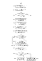
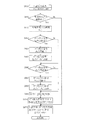
【課題】電源断からの復帰時に、電源断前のデータに基づき意図しない制御処理が実行されることを防止する。【解決手段】入力ポートのオン/オフを示すデータを記憶する入力ポートレベルデータ記憶手段と、入力ポートのオンからオフになったことを示す立ち下がりデータを記憶する入力ポート立ち下がりデータ記憶手段とを備える。電源断からの復帰時は、メイン処理により、入力ポートレベルデータ記憶手段のデータ及び入力ポート立ち下がりデータ記憶手段のデータを生成し(ステップS836、S837)、これらのデータの生成後、割込み処理を実行する(ステップS840)。割込み処理では、入力ポートの信号の読み込み処理を定期的に実行し、入力ポートレベルデータ記憶手段及び入力ポート立ち下がりデータ記憶手段のデータを更新する。【選択図】図36An object of the present invention is to prevent an unintended control process from being executed based on data before power is turned off when the power is turned off. Input port level data storage means for storing data indicating on / off of an input port; and input port falling data storage means for storing falling data indicating that the input port has been turned off. Is provided. At the time of recovery from power interruption, the main process generates the data of the input port level data storage means and the data of the input port falling data storage means (steps S836 and S837), and after generating these data, performs the interrupt process. Execute (step S840). In the interrupt processing, input port signal reading processing is periodically executed to update the data in the input port level data storage means and the input port falling data storage means. [Selection] Figure 36
Description
本発明は、電源断からの復帰時に意図しない制御処理が実行されることを防止する遊技機に関するものである。 The present invention relates to a gaming machine that prevents an unintended control process from being executed when returning from a power failure.
従来の遊技機において、電源断が発生したときであってもRWMのデータを消去せず、電源が投入されたとき(電源断からの復帰時)に、異常に対応した報知を実行する遊技機が知られている(たとえば、特許文献1参照)。 In a conventional gaming machine, even when a power interruption occurs, the RWM data is not erased, and when the power is turned on (when returning from a power interruption), a gaming machine that executes a notification corresponding to the abnormality Is known (see, for example, Patent Document 1).
前述の従来の技術において、電源断に基づきRWMのデータを消去しないと、電源断からの復帰時に、意図しない制御処理が実行されるおそれがある。
具体的には、たとえば設定変更スイッチがオンの状態であるときに電源断となり、電源断中に設定変更スイッチがオフにされ、その後、電源が投入されると、電源断時に設定変更スイッチがオンである旨のデータが残ってしまい、設定変更スイッチがオンであることに基づく制御処理が実行されるおそれがある。
本発明が解決しようとする課題は、電源断からの復帰時に、電源断前のデータに基づき意図しない制御処理が実行されることを防止することである。
In the above-described conventional technique, if the RWM data is not erased due to the power interruption, an unintended control process may be executed upon recovery from the power interruption.
Specifically, for example, when the setting change switch is in the ON state, the power is cut off, and the setting change switch is turned off while the power is turned off. Then, when the power is turned on, the setting change switch is turned on when the power is turned off. May remain, and control processing based on the setting change switch being on may be executed.
The problem to be solved by the present invention is to prevent an unintended control process from being executed based on data before power-off at the time of recovery from power-off.
本発明は、以下の解決手段によって上述の課題を解決する。なお、かっこ書きで、対応する実施形態の構成を示す。
本発明は、
遊技の進行を制御するメイン処理(M_MAIN)と、
前記メイン処理の実行中に、前記メイン処理とは異なる処理を割込みによって実行する割込み処理(I_INTR)と
を実行可能とし、
設定値を確認するときに操作される設定キースイッチ(52)の信号が入力される入力ポート(入力ポート1)と、
前記設定キースイッチのオン/オフを示すデータを記憶する入力ポートレベルデータ記憶手段(F00A;入力ポート1レベルデータ)と、
前記設定キースイッチがオンからオフになったことを示す立ち下がりデータを記憶する入力ポート立ち下がりデータ記憶手段(F00C;入力ポート1立ち下がりデータ)と
を備え、
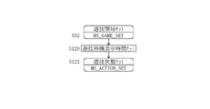
前記設定キースイッチの操作に基づいて設定値を確認可能な所定の状態(ステップS411で「Yes」のときに移行する設定確認状態)に移行可能とし、
前記設定キースイッチの立ち下がりデータに基づいて前記所定の状態を終了可能とし(ステップS416で「Yes」)、
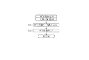
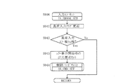
電源断から復帰したときは、前記割込み処理を実行する前に、前記メイン処理により、前記入力ポートに入力されている信号に基づいて、前記入力ポートレベルデータ記憶手段のデータと前記入力ポート立ち下がりデータ記憶手段のデータとを更新し(ステップS836、S837)、
前記更新の後に前記割込み処理を実行可能とし(ステップS840)、
前記更新の後の前記割込み処理により、再度、前記入力ポートに入力されている信号に基づいて、前記入力ポートレベルデータ記憶手段のデータと前記入力ポート立ち下がりデータ記憶手段のデータとを更新する(ステップS607)ことにより、電源断から復帰したときの前記入力ポート立ち下がりデータ記憶手段のデータを最新のデータに更新する
ことを特徴とする。
The present invention solves the above problems by the following means. The configuration of the corresponding embodiment is shown in parentheses.
The present invention
The main process (M_MAIN) that controls the progress of the game,
During execution of the main process, it is possible to execute an interrupt process (I_INTR) that executes a process different from the main process by an interrupt,
An input port (input port 1) to which a signal of a setting key switch (52) operated when confirming a set value is input;
Input port level data storage means (F00A;
Input port falling data storage means (F00C;
It is possible to shift to a predetermined state in which the setting value can be confirmed based on the operation of the setting key switch (a setting confirmation state that shifts to “Yes” in step S411),
Based on the falling data of the setting key switch, the predetermined state can be ended (“Yes” in step S416),
When recovering from power- off, before executing the interrupt process, the main process determines the data of the input port level data storage means and the input port fall based on the signal input to the input port. Update the data in the data storage means (steps S836, S837),
After the update, the interrupt process can be executed (step S840),
By the interrupt processing after the update, the data of the input port level data storage means and the data of the input port falling data storage means are updated again based on the signal input to the input port ( In step S607), the data stored in the input port falling data storage means when the power supply is restored from the power interruption is updated to the latest data .
請求項1の発明によれば、電源断から復帰したときは、入力ポートレベルデータ記憶手段及び入力ポート立ち下がりデータ記憶手段のデータを最新の状態に更新した後に割込み処理を実行可能とする。そして、割込み処理により、再度、入力ポートレベルデータ記憶手段及び入力ポート立ち下がりデータ記憶手段のデータを更新する。これにより、電源断から復帰したときに意図しない制御処理が実行されることを防止することができる。 According to the first aspect of the present invention, when the power supply is recovered from the interruption, the interrupt processing can be executed after the data in the input port level data storage means and the input port falling data storage means are updated to the latest state . Then, the data in the input port level data storage means and the input port falling data storage means is updated again by the interrupt process. As a result, it is possible to prevent an unintended control process from being executed when the power supply is recovered from a power interruption.
本明細書において、用語の意味は、以下の通りである。
「遊技媒体」とは、遊技の用に供する媒体をいい、本実施形態では「メダル(遊技メダル)」である。ただしこれに限らず、遊技球を使用することも可能である。また、遊技媒体には、実際のメダルの他に、遊技機内部に電気的に貯留(クレジット、記憶)された遊技媒体(遊技媒体に係るデータ)も含まれる。
なお、「遊技媒体」は「数」と称し、「メダル」は「枚数」と称する。
「ベット」とは、遊技を行うためにメダル(遊技媒体)を賭けることをいう。本実施形態において、1遊技での最大ベット枚数(限界枚数)は、通常遊技では3枚、1BB遊技中では2枚に設定されている。なお、これに限らず、1BB遊技中の最大ベット数を1枚又は3枚(通常遊技と同じ)に設定することも可能である。
また、「規定数」とは、スタートスイッチ41の操作が可能、すなわち遊技開始可能なメダル枚数を指し、当該遊技における最大ベット枚数である「限界枚数」とは異なる。
In the present specification, the meanings of terms are as follows.
The “game medium” refers to a medium used for a game, and is a “medal (game medal)” in the present embodiment. However, the present invention is not limited to this, and a game ball can be used. In addition to the actual medals, the game media include game media (data related to the game media) that are electrically stored (credit, stored) inside the gaming machine.
“Game media” is called “number”, and “medal” is called “number”.
“Bet” refers to betting a medal (game medium) to play a game. In the present embodiment, the maximum bet number (limit number) in one game is set to 3 in the normal game and 2 in the 1BB game. However, the present invention is not limited to this, and the maximum bet number during 1BB game can be set to 1 or 3 (same as the normal game).
The “specified number” refers to the number of medals that can be operated by the
「貯留」とは、上記「ベット」とは異なり、スロットマシン10内部にメダルをクレジットすることをいう。「貯留」は、ベットを含む意味で用いられる場合もあるが、本明細書では、「貯留」というときは、「ベット」を含まない意味で使用する。本実施形態において、貯留可能な最大枚数(上限枚数)は、遊技状態等にかかわらず、50枚に設定されている。
“Reservation” refers to crediting a medal into the
「手入れ」とは、遊技者が、後述するメダル投入口44からメダルを直接投入することをいう。
「手入れベット」とは、遊技者が、メダル投入口44からメダルを手入れすることにより、メダルをベットする(ベット数を加算する)ことをいう。
「手入れ貯留」とは、遊技者が、メダル投入口44からメダルを手入れすることにより、メダルを貯留する(クレジット数(貯留枚数)を加算する)ことをいう。
「ベットメダル」とは、ベットされているメダルをいう。
「貯留メダル」とは、クレジットとして貯留されているメダルをいう。
“Care” means that a player directly inserts medals from a
The “care bet” means that the player bets a medal (adds the number of bets) by cleaning the medal from the
“Maintenance storage” means that a player stores medals by adding medals from the medal insertion slot 44 (adds the number of credits (stored number)).
“Bet medal” means a bet medal.
“Reserved medals” refers to medals stored as credits.
「貯留ベット」とは、遊技者が後述するベットスイッチ40を操作することにより、当該遊技でベット可能な範囲内において、クレジットとして貯留されているメダルの一部又は全部を、遊技を行うためにベットすることをいう。
「自動ベット」とは、リプレイが入賞したときに、スロットマシン10の内部制御処理により、前回遊技でベットされていた数のメダルを自動でベットすることをいう。なお、上記の手入れベットしたメダル、貯留ベットしたメダル、及び貯留メダルは、その後に精算可能であるが、リプレイの入賞により自動ベットされたメダルは精算を行うことができないように設定されている。
The “reserved bet” is a game in which a player operates a
“Automatic bet” means that when a replay wins, the number of medals bet in the previous game is automatically bet by the internal control processing of the
「投入」とは、上記の手入れベット、手入れ貯留、貯留ベット、及び自動ベットを含み、メダルをベット又は貯留することをいう。
「精算」とは、ベットメダル及び/又は貯留メダルを遊技者に対して払い出すことをいう。
“Inserting” means betting or storing medals, including the above-described care bets, care storage, storage bets, and automatic bets.
“Checkout” refers to paying out a bet medal and / or a stored medal to a player.
「払出し」とは、精算によりメダルを払い出すこと、又は役の入賞に基づきメダルを遊技者に払い出すことをいう。さらに、役の入賞に基づきメダルを遊技者に払い出すときは、クレジットとして貯留すること、又は払出し口14からの実際のメダルを払い出すことをいう。本実施形態における払出しは、50枚を限界枚数として貯留し、役の入賞に基づき貯留枚数が50枚を超えた分のメダルは、遊技者に対して払い出すように制御する。また、役の入賞によって遊技者が獲得するメダル枚数を指す「獲得枚数」は、払出し枚数と同義である。
また、「メダルの飲み込み」とは、メダル投入口44からメダルが投入された場合において、ブロッカ47がオンとなっている状態で(メダルが返却されず)、メダルが正しくベット又は貯留されないことをいう。
“Payout” means that a medal is paid out by payment or a medal is paid out to a player based on a winning combination. Furthermore, when a medal is paid out to a player based on a winning combination, it means to store it as a credit or to pay out an actual medal from the
Also, “medal swallowing” means that when a medal is inserted from the
以下、図面等を参照して、本発明の一実施形態について説明する。
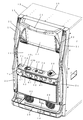
図1は、本実施形態のスロットマシン10(遊技機)を示す外観斜視図である。
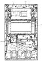
また、図2は、図1中、スロットマシン10のフロントカバー11を内面側から見た(遊技者側を見た)正面図である。
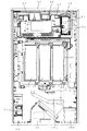
さらに、図3は、図1中、フロントカバー11を開放し、基体部12の内部を遊技者側から見た正面図である。
以下の図1〜図3の説明では、スロットマシン10に設けられている各装置の配置を中心に説明し、各装置の具体的説明は、後述する図4(ブロック図)等において行う。
Hereinafter, an embodiment of the present invention will be described with reference to the drawings.
FIG. 1 is an external perspective view showing a slot machine 10 (game machine) according to the present embodiment.
FIG. 2 is a front view of the
Further, FIG. 3 is a front view of the inside of the
In the following description of FIGS. 1 to 3, the arrangement of each device provided in the
図1に示すように、スロットマシン10の筐体は、フロントカバー11(「前扉」ともいう。)と、フロントカバー11によって前面側を閉じられた基体部12(「裏箱」又は「キャビネット」ともいう。)とから構成されている。図1では図示しないが、フロントカバー11を開けると、その開放が後述するドアスイッチ16によって検知される。
As shown in FIG. 1, the housing of the
このフロントカバー11は、基体部12の前面(開口面)を覆うようにして、基体部12に開閉可能に取り付けられたものである。図1に示すように、フロントカバー11の遊技者側には、ベットスイッチ40、スタートスイッチ41、3つのストップスイッチ42、メダル投入口44等が配置されている。さらに、ベットスイッチ40の左側には、貯留数表示LED71、獲得数表示LED72及び状態表示LED73が設けられている。
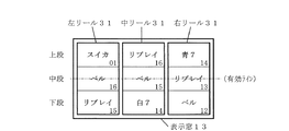
また、フロントカバー11の略中央部には、内部に配置されたリール31の一部が透視可能に形成された表示窓13が形成されている。
なお、表示窓13上(たとえば、リール31の視認領域の左側)に、貯留数表示LED71、獲得数表示LED72及び情報表示LED73を設けることも可能である。この場合、後述する表示基板70は、表示窓13の裏面側に配置される。
The
A
Note that a storage
さらにまた、フロントカバー11の上方部及び側面部には、略枠状に演出ランプ21(フロントカバー11に設けられた当該ランプを枠ランプ21と称する場合がある)が配置されている。さらに、表示窓13の上方部には、画像表示装置23が設けられ、さらにその両側にはスピーカ22が配置されている。
さらに、フロントカバー11の下方部には、メダル払出し口14と、メダル受け皿15が設けられている。さらにまた、メダル払出し口14の両側にもスピーカ22が設けられている。
Furthermore, an effect lamp 21 (the lamp provided on the
Further, a
図2に示すように、フロントカバー11の裏面側において、表示窓13の上方部、すなわち画像表示装置23が配置されている部分には、画像表示装置23に重なるように、透明な基板ケース19が設けられている。そして、この基板ケース19内に、サブ制御基板(サブ制御手段)80が配置されている。
As shown in FIG. 2, on the back surface side of the
一方、基体部12は、木材等を組み立てて、前面側が開口する中空箱形に構成したものである。そして、図3に示すように、基体部12の内部において、その下方部には、スロットマシン10の電源をオン/オフする電源スイッチ51を有する電源ユニット50と、ホッパータンク35aを含むメダル払出し装置35が設けられている。なお、図3中、ホッパー35aの右側には、ホッパー35aからあふれたメダルを収容するためのサブタンク35bが配置されている。
On the other hand, the
また、メダル払出し装置35の上方部には、板状のリールベースが固定されており、このリールベース上に、3つのリール31を含む図柄表示装置30が設けられている。そして、リール31上には、後述するように図柄が配置されており、リール31上の図柄が表示窓13を通して遊技者から視認可能となっている。
A plate-shaped reel base is fixed to the upper part of the
さらにまた、基体部12の内面側であって、図柄表示装置30の上側には、透明な基板ケース17が設けられ、この基板ケース17内にメイン制御基板(メイン制御手段)60が配置されている。基板ケース17は、メイン制御基板60の不正(ROM交換等)を防止するため、メイン制御基板60を内部に収容した後、かしめや、溶着(超音波による溶着、UV硬化剤による溶着、電熱による溶着等)により封止されている。このメイン制御基板60は、上述したサブ制御基板80と、図示しないハーネスや光ファイバー(電気配線の束)によって電気的に接続されている。
また、メイン制御基板60上には、設定値を表示するための設定値表示LED63(セブンセグメントLED)が実装されている。
Furthermore, a
A set value display LED 63 (seven segment LED) for displaying the set value is mounted on the
さらに、図3に示すように、基板ケース17の右側に隣接するように、透明なドア(設定ドア)18が設けられ、このドア18の内側に、メイン制御基板60とは別の基板(メイン制御基板60と電気的に接続されている基板)が設けられている。そして、この基板上に設定キースイッチ52及び設定変更/リセットスイッチ53が実装されている。したがって、設定キースイッチ52及び設定変更/リセットスイッチ53は、ドア18によって覆われている。また、ドア18を開閉したか否かを検知するための設定ドアスイッチ54(後述)が設けられている。
Further, as shown in FIG. 3, a transparent door (setting door) 18 is provided adjacent to the right side of the
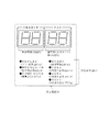
図4は、図1中、貯留数表示LED71、獲得数表示LED72及び状態表示LED73を拡大して示す平面図である。図2に示すように、これらのLED71〜73は、表示基板70上に搭載されている。
貯留数表示LED71は、貯留メダル枚数を表示するLEDであり、2桁を表示するために、2つのセブンセグメントディスプレイ(いわゆる7セグ)から構成されている。
貯留数表示LED71は、本実施形態では、「00」〜「50」(整数)の間の数字を表示する。
FIG. 4 is an enlarged plan view showing the storage
The storage
In this embodiment, the storage
たとえば、ベット枚数が0枚、かつ貯留枚数が0枚の状態では、貯留数表示LED71の表示は、「00」となっている。ここで、1枚のメダルが手入れされると、当該遊技のためにその1枚のメダルがベットされる。さらに2枚を追加投入すると、当該遊技のために3枚のメダルがベットされる(ベット限界枚数が3枚の場合)。したがって、限界枚数が3枚の場合において、それ以前のベット枚数が0枚であれば、手入れされたメダルが3枚までのときは、そのメダルはベットされ、貯留されない。さらにメダルが手入れされ続けると、そのメダルが貯留されるとともに、その貯留枚数が貯留数表示LED71によって表示される。
For example, when the bet number is 0 and the stored number is 0, the display of the stored
したがって、たとえばベットメダル枚数が0枚、貯留メダル枚数が0枚の状態において、当該遊技におけるベットメダル限界枚数が3枚であるとき、4枚のメダルをメダル投入口44から投入すると、3枚のメダルがベットされるとともに1枚のメダルが貯留される。その結果、貯留数表示LED71には「01」と表示される。
Therefore, for example, when the number of bet medals is 0 and the number of stored medals is 0, when the limit number of bets in the game is 3, if 4 medals are inserted from the
本実施形態では、最大で50枚までのメダルを貯留可能となっている。したがって、貯留枚数が50枚となったとき(貯留数表示LED71に「50」と表示されたとき)は、それ以上、メダルは貯留されない。この状態で、仮に、メダル投入口44からメダルが手入れされると、ブロッカ47により、手入れされたメダルは、払出し口14から返却される。
In this embodiment, up to 50 medals can be stored. Therefore, when the number of stored sheets reaches 50 (when “50” is displayed on the stored number display LED 71), medals are not stored any more. In this state, if a medal is maintained from the
獲得数表示LED72は、役の入賞時に、払出し枚数(遊技者の獲得枚数)を表示するLEDであり、貯留数表示LED71と同様に、2つのセブンセグメントディスプレイから構成されている。
なお、獲得数表示LED72は、通常は獲得枚数を表示するが、エラー発生時にはエラーの内容(種類)を表示するLEDとして機能するため、「獲得数(又はエラー)表示LED72」と称する場合もある。
The acquisition number display LED 72 is an LED for displaying the number of payouts (player acquisition number) at the time of winning a winning combination. Like the storage
The acquisition number display LED 72 normally displays the number of acquisitions, but functions as an LED that displays the content (type) of an error when an error occurs, and may be referred to as an “acquisition number (or error) display LED 72”. .
獲得数表示LED72は、払い出されるメダルがないときは、表示は「00」であるが、たとえば後述する1枚ベルが入賞して1枚のメダルが払い出されると、獲得数表示LED72の表示は、「00」から「01」となる。
なお、獲得数表示LED72は、払い出されるメダルがないときは、消灯するように制御してもよい。
The acquisition number display LED 72 is “00” when there is no medal to be paid out. For example, when one bell described later wins and one medal is paid out, the display of the acquisition number display LED 72 is: From “00” to “01”.
The acquired number display LED 72 may be controlled to be turned off when there are no medals to be paid out.
ここで、メダル払出しのある役(リプレイを除く)が入賞してその役に対応するメダルが払い出されるときは、払出し口14から払い出されることよりも優先して、メダルが貯留される。たとえば、ベル02入賞前の貯留枚数が「10」であるときは、ベル02の入賞により、獲得数表示LED72の表示が「00」から「01」に更新されるとともに、貯留数表示LED71の表示が「10」から「11」に更新される。
Here, when a combination with a medal payout (excluding replay) wins and a medal corresponding to the combination is paid out, the medal is stored in preference to being paid out from the
さらにまた、役の入賞時に、貯留枚数が50枚を超えるときは、50枚を超えた分については払出し口14から払い出さされる。たとえば、役の入賞前に貯留枚数が47枚であり、ベル01の入賞によって8枚のメダルが払い出されるとき、3枚は貯留されて貯留枚数が50枚となり、50枚を超える分に相当する5枚については払出し口14から払い出される。
Furthermore, if the number of stored sheets exceeds 50 at the time of winning a winning combination, the portion exceeding 50 is paid out from the
さらに、リプレイの入賞時は、メダルの貯留及び払出しは行われず、当該遊技でベットされていた枚数のメダルが再遊技のために自動ベットされる。たとえば、当該遊技を2ベット(2枚)で行い、リプレイが入賞したときは、2枚のメダルが自動ベットされる。同様に、当該遊技を3ベット(3枚)で行い、リプレイが入賞したときは、3枚のメダルが自動ベットされる。そして、リプレイの入賞に基づく自動ベットは、再遊技を行うためのメダルの投入であるので、その後に精算(返却)操作を行っても、当該メダルを精算することはできない。また、リプレイ入賞後にメダルを投入することは可能であり、投入されたメダルはクレジットとして貯留される。 Further, at the time of replay winning, medals are not stored and paid out, and the number of medals bet in the game are automatically bet for replay. For example, if the game is played with 2 bets (2) and a replay wins, 2 medals are automatically bet. Similarly, when the game is played with 3 bets (3 cards) and the replay wins, 3 medals are automatically bet. Since the automatic bet based on the replay winning is the insertion of medals for replaying, even if the settlement (return) operation is performed thereafter, the medals cannot be settled. In addition, it is possible to insert medals after a replay win, and the inserted medals are stored as credits.
なお、「遊技機の認定及び型式の検定等に関する規則」では、リプレイに対応する図柄の組合せが有効ラインに停止したときは、メダル等の投入をすることによらずに行う遊技を付与することとされ、「入賞(メダル等を獲得するための図柄の組合せが表示されること)」ではないと解釈されている。しかし、本願(本明細書等)では、リプレイについても役の1つとして扱い(再遊技役)、リプレイに対応する図柄の組合せが有効ラインに停止したことを「リプレイの入賞」と称する。 In addition, in the “Rules for Game Machine Approval and Type Approval”, when a combination of symbols corresponding to a replay is stopped on the active line, a game to be performed without giving a medal or the like is given. It is interpreted that it is not “winning (displaying a combination of symbols for obtaining medals etc.)”. However, in the present application (this specification and the like), replay is also treated as one of the roles (replaying game), and the combination of symbols corresponding to the replay is stopped on the active line is referred to as “replay winning”.
また、状態表示LED73は、本実施形態では、図4に示す7個のLED73a〜73gを備える。
リプレイ表示LED73aは、リプレイの入賞時に点灯するLEDである。リプレイの入賞に基づく自動ベットが行われると、リプレイ表示LED73aが点灯し、自動ベット状態であることを遊技者に知らせる。
Moreover, the status display LED 73 includes seven LEDs 73a to 73g shown in FIG. 4 in the present embodiment.
The replay display LED 73a is an LED that is lit when a replay is won. When an automatic bet based on a replay win is made, the replay display LED 73a is lit to inform the player that the bet is in an automatic state.
投入可表示LED73bは、メダルを投入(ベット)可能な状態のときに点灯するLEDである。すなわち、遊技が終了し、次遊技に移行するためのメダルが投入される前に点灯し、いわゆるベット待ち状態を示す。なお、本実施形態ではリプレイが作動した後であっても貯留枚数に応じてベット可能なときには点灯する。
精算表示LED73cは、本実施形態では、精算処理中に点灯するLEDである。貯留メダル及び/又はベットメダル(リプレイ入賞時の自動ベットを除く)を有する状態で、精算スイッチ43がオンされたときに、メダルを実際に払い出している最中に点灯する。
The insertion-possible display LED 73b is an LED that lights when a medal can be inserted (bet). That is, it lights up before the game is finished and a medal for shifting to the next game is inserted, indicating a so-called bet waiting state. In the present embodiment, even after the replay is activated, it lights up when a bet can be made according to the number of stored items.
In the present embodiment, the settlement display LED 73c is an LED that is lit during the settlement process. When the settlement switch 43 is turned on in a state where there is a stored medal and / or a bet medal (excluding an automatic bet at the time of replay winning), it lights up while the medal is actually paid out.
遊技開始LED73dは、規定数のメダルがベットされ、スタートスイッチ41を操作可能な状態となったときに点灯するLEDである。したがって、規定数のメダルがベットされていない(又はリプレイの自動投入がされていない)状態では点灯しない。本実施形態では、限界枚数が「2枚」であるときは規定数は「2枚」となり、限界枚数が「3枚」であるときは規定数は「3枚」となるように定められている。
The game start LED 73d is an LED that is lit when a specified number of medals are bet and the
(1枚、2枚、3枚)投入表示LED73e〜73gは、それぞれ、ベットされているメダル枚数を表示するLEDである。1枚のメダルがベットされたときは1枚投入表示LED73eが点灯し、2枚のメダルがベットされたときは、1枚投入表示LED73e及び2枚投入表示LED73fが点灯し、3枚のメダルがベットされたときは、1枚投入表示LED73e、2枚投入表示LED73f及び3枚投入表示LED73gが点灯する。 The (1, 2, 3) insertion display LEDs 73e to 73g are LEDs for displaying the number of medals bet. When one medal is bet, the one-insertion display LED 73e is lit. When two medals are bet, the one-insertion display LED 73e and the two-insertion display LED 73f are lit, and three medals are displayed. When a bet is placed, the 1-sheet insertion display LED 73e, the 2-sheet insertion display LED 73f, and the 3-sheet insertion display LED 73g are lit.
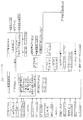
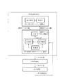
図5は、本実施形態におけるスロットマシン10の制御の概略を示すブロック図である。
スロットマシン10は、上述したようにメイン制御基板60とサブ制御基板80とを備える。
メイン制御基板60は、入力ポート(0〜2)及び出力ポート(0〜6)を有し、RWM(メインメモリ)61、メインCPU62等を備える(図5で図示したもののみを備える意味ではない)。
FIG. 5 is a block diagram showing an outline of control of the
The
The
なお、実際には、メイン制御基板60上には、メインCPU62、RWM61、ROM、及びレジスタを含むMPUが搭載される。なお、ROMは、MPU内部に搭載されるもの以外に、外部ROMを備えていてもよい。一方、RWM61は、現行規則により、MPU内部にのみ設けられる。また、後述するサブ制御基板80については、MPU外部にRWMを設けることができる。
したがって、メインCPU62というときは、MPUを含む意味で使用する。
また、RWM61(記憶手段)というときは、MPU内蔵のRWM61、ROM(内部/外部)、及びレジスタ(記憶回路)を含む意味で使用する。
In practice, an MPU including a main CPU 62, an RWM 61, a ROM, and a register is mounted on the
Therefore, the main CPU 62 is used to include MPU.
The term RWM 61 (storage means) is used to include the RWM 61 with built-in MPU, ROM (internal / external), and register (storage circuit).
メイン制御基板60と、ベットスイッチ40等の操作スイッチを含む遊技進行用の周辺機器とは、入力ポート又は出力ポートを介して電気的に接続されている。入力ポートは、操作スイッチ等の信号が入力される接続部であり、出力ポートは、モータ32等の周辺機器に対して信号を送信する接続部である。
なお、図5において、入力用の周辺機器は、その周辺機器からの信号がメイン制御基板60に向かう矢印で表示しており、出力用の周辺機器は、メイン制御基板60からその周辺機器に向かう矢印で示している。
The
In FIG. 5, the input peripheral device displays a signal from the peripheral device as an arrow directed to the
RWM(メインメモリ)61は、遊技の進行等に基づいた各種データを記憶(更新)可能な記憶媒体である。
ROMは、遊技の進行に必要なプログラムや各種データ(たとえば、データテーブル)等を記憶しておく記憶媒体である。
メインCPU62は、メイン制御基板60上に設けられたCPUを指し、遊技の進行に必要なプログラムの実行、演算等を行い、具体的には、役の抽選、リール31の駆動制御、及び入賞時の払出し等を実行する。
The RWM (main memory) 61 is a storage medium capable of storing (updating) various data based on the progress of the game.
The ROM is a storage medium that stores programs necessary for the progress of the game, various data (for example, a data table), and the like.
The main CPU 62 refers to a CPU provided on the
メダル投入口44から投入されたメダルは、メダルセレクタ45を通過するように構成されている。
メダルセレクタ45は、図5に示すように、通路センサ46、ブロッカ47、投入センサ48a及び48bを備え(ただし、これらに限定されるものではない)、メイン制御基板60と電気的に接続されている。
メダル投入口44からメダルが投入されると、最初に、通路センサ46により検知されるように構成されている。
The medals inserted from the
As shown in FIG. 5, the
When a medal is inserted from the
さらに、通路センサ46の下流側には、ブロッカ47が設けられている。ブロッカ47は、メダルの通路中に設けられ、メダルの通過(投入)を許可/不許可にするためのものであり、メダルの投入が不許可状態のときは、メダル投入口44から投入されたメダルを払出し口14から返却するメダル通路を形成する。これに対し、メダルの投入が許可状態のときは、メダル投入口44から投入されたメダルをホッパー35aに案内するメダル通路を形成する。
また、後述するように、ブロッカ47の状態として、メダルの投入を許可する状態をオン状態と称し、メダルの投入を不許可する状態をオフ状態と称する。
Further, a blocker 47 is provided on the downstream side of the passage sensor 46. The blocker 47 is provided in the medal passage, and is used to allow / disallow medal passage (insertion). When the medal insertion is not permitted, the blocker 47 is inserted from the
As will be described later, as a state of the blocker 47, a state where the insertion of medals is permitted is referred to as an on state, and a state where the insertion of medals is not permitted is referred to as an off state.
ここで、ブロッカ47は、遊技中(リール31の回転開始時から、全リール31が停止し、役の入賞時には入賞役に対応する払出しの終了時まで)は、メダルの投入を不許可(オフ)状態とする。すなわち、ブロッカ47がメダルの投入を許可するのは、少なくとも遊技が行われていないときである。
Here, the blocker 47 does not allow the insertion of medals during the game (from the start of the rotation of the
ブロッカ47のさらに下流側には、投入センサ48a及び48b(光学センサ)が設けられている。したがって、メダル投入口44から投入されたメダルは、通路センサ46によって検知された後、さらに、投入センサ48a(上流側)及び48b(下流側)により検知されるように構成されている。なお、図5に示すように、後述する説明においては、上流側の投入センサ48aを投入センサ1、下流側の投入センサ48bを投入センサ2と称する場合もある。
On the further downstream side of the blocker 47, input sensors 48a and 48b (optical sensors) are provided. Therefore, medals inserted from the
また、図5に示すように、メイン制御基板60には、遊技者が操作する操作スイッチとして、精算スイッチ43、ベットスイッチ40、スタートスイッチ41、(左、中、右)ストップスイッチ42が電気的に接続されている。
Further, as shown in FIG. 5, the
精算スイッチ43は、スロットマシン10内部に貯留(クレジット)されたメダルを払い戻す(ペイアウトする)ときに遊技者が操作するスイッチである。
ベットスイッチ40は、貯留されたメダルを当該遊技のためにベットするときに遊技者が操作するスイッチである。本実施形態におけるベットスイッチ40は、1枚(1遊技における最小枚数)をベットするための1ベットスイッチ40aと、当該遊技でベット可能な最大枚数のメダルをベットするための3ベットスイッチ40bとを備える。
なお、これに限らず、2枚ベット用のベットスイッチを設けてもよい。また、1枚、2枚、3枚ベット用のベットスイッチ40のうち、スロットマシン10の仕様に応じて、2つ又は3つ設けることも可能である。
The settlement switch 43 is a switch operated by the player when paying out (paying out) medals stored (credited) in the
The
However, the present invention is not limited to this, and a bet switch for two bets may be provided. Of the bet switches 40 for one, two, and three bets, two or three can be provided depending on the specifications of the
そして、「ベットスイッチに対応するベット枚数」とは、ベットスイッチが1ベットスイッチ40aであるときは1枚、3ベットスイッチ40bであるときは3枚を意味する。また、2枚ベット用のベットスイッチを設けたときは、そのベットスイッチに対応するベット数は2枚となる。
3ベットスイッチ40bは、いずれにしてもそのときにベット可能な最大枚数を加算するベットスイッチであるので、マックスベットスイッチとも称される。本実施形態では、説明の便宜上、3ベットスイッチ40bと称する。
The “number of bets corresponding to the bet switch” means 1 when the bet switch is the 1
Since the 3-bet switch 40b is a bet switch that adds the maximum number of bets that can be made at any time, it is also referred to as a max bet switch. In the present embodiment, for convenience of explanation, it is referred to as a 3-bet switch 40b.
ここで、1遊技の限界枚数は、上述したように、1BB遊技中では2枚、1BB遊技中以外(通常遊技)では3枚である。
たとえば通常遊技において、既にベットされているメダル枚数(既ベット枚数)が0枚の場合に、3ベットスイッチ40bが操作され、かつ貯留枚数が3枚以上であるときは、3枚がベットされる。
また、通常遊技において、既ベット枚数が0枚の場合に、3ベットスイッチ40bが操作され、かつ貯留枚数が2枚であるときは、ベット可能な最大枚数は2枚であるので、2枚がベットされる。
Here, as described above, the limit number of one game is two during the 1BB game, and is three when the game is not during the 1BB game (normal game).
For example, in a normal game, when the number of medals already bet (the number of existing bets) is 0, when the 3-bet switch 40b is operated and the stored number is 3 or more, 3 bets are bet. .
In a normal game, when the number of already bet is 0, when the 3-bet switch 40b is operated and the number of reserves is 2, the maximum possible bet is 2, so 2 Bet.
さらにまた、通常遊技において、既ベット枚数が1枚の場合に、3ベットスイッチ40bが操作され、かつ貯留枚数が2枚以上であるときは、ベット可能な最大枚数は2枚であるので、2枚がベット(それまでのベット枚数に加算)される。
さらに、通常遊技において、既ベット枚数が3枚の場合に、3ベットスイッチ40bが操作されたときは、貯留枚数を有するときであっても、ベット(加算)可能な枚数は0枚であるので、ベット枚数は加算されない。
Furthermore, in the normal game, when the number of already bet is 1, when the 3-bet switch 40b is operated and the stored number is 2 or more, the maximum betable number is 2, so 2 A bet is placed (added to the previous bet number).
Further, in the normal game, when the number of already bet is 3, when the 3-bet switch 40b is operated, the number of bets that can be added (added) is 0 even when the reserve number is available. The bet number is not added.
また、通常遊技において、既ベット枚数が1枚であり、かつ貯留枚数が1枚である場合に、3ベットスイッチ40bが操作されたときは、ベット可能な最大枚数は1枚であるので、1枚がベットされる。その結果、それまでの既ベット数である1枚に新たにベット枚数1枚が加算され、3ベットスイッチ40bの操作後のベット枚数は2枚となる。
さらにまた、1BB遊技において、既ベット枚数が0枚の場合に、3ベットスイッチ40bが操作され、かつ貯留枚数が2枚以上であるときは、ベット可能な最大枚数は2枚であるので、2枚がベットされる。
Further, in the normal game, when the number of already bet is one and the number of reserved is one, when the 3-bet switch 40b is operated, the maximum number that can be bet is one. A bet is placed. As a result, one bet number is newly added to the existing bet number, and the bet number after the operation of the 3-bet switch 40b becomes two.
Furthermore, in the 1BB game, when the bet number is 0, when the 3-bet switch 40b is operated and the stored number is 2 or more, the maximum betable number is 2, so 2 A bet is placed.
スタートスイッチ41は、(左、中、右のすべての)リール31を始動させるときに遊技者が操作するスイッチである。
さらにまた、ストップスイッチ42は、3つ(左、中、右)のリール31に対応して3つ設けられ、対応するリール31を停止させるときに遊技者が操作するスイッチである。
The
Furthermore, three
また、図5に示すように、メイン制御基板60には、表示基板70が電気的に接続されている。なお、実際には、メイン制御基板60と表示基板70との間には、中継基板が設けられ、メイン制御基板60と中継基板、及び中継基板と表示基板70とが接続されているが、図5では中継基板の図示を省略している。このように、メイン制御基板60と表示基板70とは、直接ハーネス等で接続されていてもよいが、両者間に別の基板が介在してもよい。
さらに、制御基板同士が直接(ハーネス等で)接続されていることに限らず、他の別基板(中継基板等)を介して接続されていてもよい。たとえば、メイン制御基板60とサブ制御基板80との間に1つ以上の他の別基板(中継基板等)が介在してもよい。
Further, as shown in FIG. 5, a
Furthermore, the control boards are not limited to being directly connected (via a harness or the like), but may be connected via another separate board (a relay board or the like). For example, one or more other boards (such as relay boards) may be interposed between the
表示基板70には、上述した貯留数表示LED71、獲得数表示LED72、及び状態表示LED73が接続されている。これらのLED71〜73は、図1に示すように、遊技者が操作する操作スイッチの左側端部に設けられ、遊技者が常に視認できる位置に設けられている。なお、1つの表示基板70上にすべてのLED71〜73が設けられている必要はなく、たとえば表示基板70A、70B、・・・のように複数の表示基板70を備え、いずれかの表示基板70にいずれかのLED71〜73が設けられていればよい。
The
さらに、表示窓13上(たとえば、リール31の視認領域の左側)に、貯留数表示LED71、獲得数表示LED72及び情報表示LED73を設けることも可能である。この場合、表示基板70は、表示窓13の裏面側に配置される。
Furthermore, a storage
メイン制御基板60には、図柄表示装置30のモータ32等が電気的に接続されている。
図柄表示装置30は、図柄を表示する(本実施形態では3つの)リール31と、各リール31をそれぞれ駆動するモータ32と、リール31の位置を検出するためのリールセンサ39とを含む。
The
The
モータ32は、リール31を回転させるためのものであり、各リール31の回転中心部に連結され、後述するリール制御手段62cによって制御される。ここで、リール31は、左リール31、中リール31、右リール31からなり、左リール31を停止させるときに操作するストップスイッチ42が左ストップスイッチ42であり、中リール31を停止させるときに操作するストップスイッチ42が中ストップスイッチ42であり、右リール31を停止させるときに操作するストップスイッチ42が右ストップスイッチ42である。
The
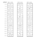
リール31は、リング状のものであって、その外周面には複数種類の図柄(役に対応する図柄の組合せを構成している図柄)を印刷したリールテープを貼付したものである。なお、リール31上の図柄の具体的配置は、後述する(図22)。
The
また、各リール31には、1個(2個以上であってもよい)のインデックスが設けられている。インデックスは、リール31の例えば周側面に凸状に設けられており、リール31が所定位置を通過したか否かや、1回転したか否か等を検出するときに用いられる。そして、各インデックスは、リールセンサ39により検知される。リールセンサ39の信号は、メイン制御基板60に電気的に接続されている。そして、リールセンサ39がインデックスを検知する(切る)と、その入力信号がメイン制御基板60に入力され、そのリール31が所定位置を通過したことが検知される。
Each
また、リールセンサ39がリール31のインデックスを検知した瞬間の基準位置上の図柄を予めRWM61(メインROM)に記憶している。これにより、インデックスを検知した瞬間の基準位置上の図柄を検知することができる。
また、メイン制御基板60には、メダル払出し装置35が電気的に接続されている。メダル払出し装置35は、メダルを溜めておくためのホッパー35aと、ホッパー35aのメダルを払出し口14から払い出すときに駆動するホッパーモータ36と、ホッパー35aから払い出されたメダルを検出するための払出しセンサ37a及び37bを備える。
Further, the symbol on the reference position at the moment when the reel sensor 39 detects the index of the
The
メダル投入口44から手入れされ、受け付けられたメダルは、所定の通路(「シュート部」とも称する。)を通してホッパー35a内に収容されるように形成されている。
払出しセンサ37a及び37bは、投入センサ48a及び48bと同様に、上流側に払出しセンサ37aが設けられ、下流側に払出しセンサ37bが設けられている。
The medals that are maintained and received from the
The payout sensors 37a and 37b are provided with a payout sensor 37a on the upstream side and a payout sensor 37b on the downstream side, similarly to the input sensors 48a and 48b.
払出しセンサ37aと37bとは、所定距離を隔てて配置され、メダルが払出しセンサ37aにより検知されてから所定時間を経過した後に払出しセンサ37bにより検知されるように構成されている。そして、払出しセンサ37a及び37bがそれぞれオン/オフとなるタイミングに基づいて、メダルが正しく払い出されたか否かを判断する。 The payout sensors 37a and 37b are arranged at a predetermined distance, and are configured to be detected by the payout sensor 37b after a predetermined time has elapsed since the medal was detected by the payout sensor 37a. Then, based on the timing when the payout sensors 37a and 37b are turned on / off, it is determined whether or not the medals have been paid out correctly.
たとえば、ホッパーモータ36が駆動しているにもかかわらず、払出しセンサ37a及び37bの信号がいずれもオフであるときは、メダルが払い出されていないと判断し、ホッパーエラー(メダルなし)と検知される。
一方、払出しセンサ37a又は37bの信号の少なくとも1つがオンのままとなったときは、メダル詰まりが生じたと検知する。なお、払出しセンサ37を1つだけ設け、上記エラーを検知するようにしてもよい。
For example, when the signals of the payout sensors 37a and 37b are both off despite the hopper motor 36 being driven, it is determined that no medal has been paid out, and a hopper error (no medal) is detected. Is done.
On the other hand, when at least one of the signals from the payout sensor 37a or 37b remains on, it is detected that a medal jam has occurred. Note that only one payout sensor 37 may be provided to detect the error.
満杯センサ38は、ホッパー35aから溢れたメダルを収容するサブタンク35b(図3参照)の満杯を検知するセンサであり、サブタンク35bのメダルが満杯となったときにメダルが接触することで通電する回路から構成される。 The full sensor 38 is a sensor that detects the fullness of the sub tank 35b (see FIG. 3) that stores medals overflowing from the hopper 35a, and is a circuit that is energized when the medals come into contact when the medals in the sub tank 35b become full. Consists of
また、ドアスイッチ16は、スロットマシン10のフロントカバー11を開けたときにオンとなるスイッチであり、フロントカバー11の開閉状態を検知するためのものである。
また、電源スイッチ51は、スロットマシン10の電源のオン/オフを行うスイッチである。
設定キースイッチ52は、設定キー挿入口から設定キーが挿入され、右90度に回転しているときにオンとなるスイッチであり、設定確認時や設定変更時にオンとする。
The
The power switch 51 is a switch for turning on / off the power of the
The setting key switch 52 is a switch that is turned on when a setting key is inserted from the setting key insertion slot and is rotated 90 degrees to the right, and is turned on when the setting is confirmed or the setting is changed.
設定変更/リセットスイッチ53は、1つのスイッチで設定変更スイッチとリセットスイッチとを兼ねているスイッチである。なお、設定変更スイッチとリセットスイッチとは、別々に設けられていてもよい。
設定変更/リセットスイッチ53は、設定値を変更するときに操作される。また、設定キースイッチ52をオンにしつつ電源スイッチ51がオンにされると、リセットすなわち初期化処理が行われ、RWM61に記憶されている所定のデータがクリアされる。
The setting change / reset switch 53 is a switch that serves as both a setting change switch and a reset switch. Note that the setting change switch and the reset switch may be provided separately.
The setting change / reset switch 53 is operated when changing a setting value. When the power switch 51 is turned on while the setting key switch 52 is turned on, reset, that is, initialization processing is performed, and predetermined data stored in the RWM 61 is cleared.
設定ドアスイッチ54は、上述した設定ドア(設定キースイッチ52及び設定変更/リセットスイッチ53を覆うドア)の開閉を検知するスイッチである。たとえば設定ドアスイッチ54がオフ、すなわち設定ドアが開けられていない状態で設定キースイッチ52がオンであるとき等は、エラーとなる。 The setting door switch 54 is a switch that detects opening / closing of the setting door (the door that covers the setting key switch 52 and the setting change / reset switch 53). For example, an error occurs when the setting door switch 54 is off, that is, when the setting key switch 52 is on while the setting door is not opened.
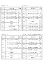
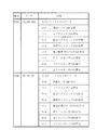
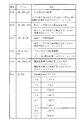
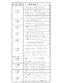
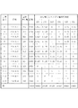
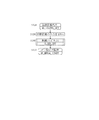
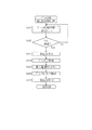
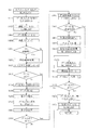
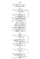
図6は、メイン制御基板60に設けられた入力ポート0〜2を示す図である。また、図7は、メイン制御基板60に設けられた出力ポート3〜6を示す図である。なお、出力ポート0〜2については、図面を用いた説明を割愛する。
本実施形態の入力ポート0〜2及び出力ポート0〜6は、D0〜D7の8ビットが入力又は出力可能な1バイトのポートである。
なお、入力ポート及び出力ポートは、図示したもの以外にも設けられているが、本実施形態では説明を省略する。
FIG. 6 is a diagram showing the
The
The input port and the output port are provided in addition to those shown in the figure, but the description thereof is omitted in this embodiment.
また、図6及び図7中、未使用と表示したポートは、実際に使用されていないか、又は本実施形態において説明を省略する信号の入出力ポートを意味する(信号の入出力がないポートは、すべて未使用という意味ではない)。 6 and 7, a port indicated as unused means a signal input / output port that is not actually used or a description of which is omitted in the present embodiment (a port without signal input / output). Does not mean all unused).
図6及び図7に示す入力ポート0〜2及び出力ポート3〜6において、「正」、「負」とは、それぞれ入力又は出力される信号を意味し、たとえば入力ポート0のD0ビット(特定のビットを指すときには「ビット目」ともいうが、以下の説明では「ビット」という。)における精算スイッチ信号では、操作されていないときにはD0ビットに「正(high)」の信号が入力され、操作されたときはD0ビットに「負(low )」の信号が入力される。換言すると、「負(low )」の信号がアクティブ信号となる。一方、たとえば3ベットスイッチ信号では、操作されていないときにはD2ビットに「負(low )」の信号が入力され、操作されたときはD2ビットに「正(high)」の信号が入力される。換言すると、「正(high)」の信号がアクティブ信号となる。
In the
さらにまた、入力ポート0において、精算スイッチ信号及び1ベットスイッチ信号は、そのスイッチの操作時にいずれも操作時に負の信号が入力されるが、3ベットスイッチ信号は、そのスイッチの操作時に正の信号が入力される。これは、本実施形態では、精算スイッチ43及び1ベットスイッチ40aと、3ベットスイッチ40bとで、異なるスイッチを用いているためである。
Furthermore, at the
たとえば、精算スイッチ43及び1ベットスイッチ40aは、押されること(あるいは押圧)に応じて接地/非接地を検出するボタンスイッチであり、押圧された場合に電流が流れる回路を備えるスイッチである。これに対し、3ベットスイッチ40bは、フォトセンサを内蔵したボタンスイッチであり、フォトセンサの受光素子が遮光片により発光素子側の光を遮光したときに電圧が変化するスイッチである。
このように、設計上の都合に応じて、同じベットスイッチ40であっても異なる構造のスイッチを採用している。なお、これに限らず、同一構造のスイッチを用いることも勿論可能である。
For example, the settlement switch 43 and the 1-bet switch 40a are button switches that detect grounding / non-grounding when pressed (or pressed), and are switches that include a circuit through which a current flows when pressed. On the other hand, the 3-bet switch 40b is a button switch with a built-in photosensor, and the voltage changes when the light receiving element of the photosensor blocks light on the light emitting element side by the light shielding piece.
As described above, switches having different structures are employed even for the
入力ポート0は、操作スイッチである精算スイッチ43、ベットスイッチ40(1ベットスイッチ40a及び3ベットスイッチ40b)、スタートスイッチ41、及び(左、中、右)ストップスイッチ42の各信号が入力される。
また、入力ポート1には、通路センサ46、ドアスイッチ16、設定ドアスイッチ54、設定キースイッチ52、設定変更/リセットスイッチ53、(左、中、右)リールセンサ39の各信号が入力される。なお、設定ドアスイッチ54を設けていない仕様のスロットマシン10であるときには、入力ポート1のD2ビットは未使用となる。
さらにまた、入力ポート2には、電断信号(電断が発生したときに出力される信号)、投入センサ1(48a)及び2(48b)の信号、払出しセンサ1(37a)及び2(37b)の信号、満杯センサ38の信号が入力される。
The
The
Furthermore, the
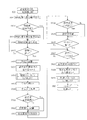
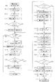
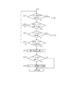
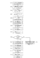
そして、後述するように、遊技を進行する情報処理として、1遊技あたり1回行うメイン処理(メインループ)(M_MAIN)が設けられている。メイン処理では、投入されたメダルの検知に基づいて行われる手入れメダルチェック処理や、全リール31が停止した後の入賞処理等が行われる処理である。
As will be described later, main processing (main loop) (M_MAIN) that is performed once per game is provided as information processing for proceeding with the game. The main process is a process in which a care medal check process performed based on detection of inserted medals, a winning process after all
このメイン処理中に、メイン処理を一旦抜けて、割込み処理(タイマ割込み処理)を実行する。そして、割込み処理では、入力ポート0〜2を検知する処理(後述する図64のステップS607)を実行し、その処理の実行後、再度、メイン処理に戻ることを定期的に行っている。その割込み時間の間隔は、本実施形態では2.235msである。すなわち、2.235ms間隔の割込み処理ごとに、入力ポート0〜2のデータを取得する。そして、取得したデータに基づいて、入力ポートのレベルデータ(各ビットのオン/オフを示すデータ)、入力ポートの立ち上がりデータ(前回割込み時がオフで、今回割込み時がオンになったデータがどのビットであるかを示すデータ)、入力ポートの立ち下がりデータ(前回割込み時がオンで、今回割込み時がオフになったデータがどのビットであるかを示すデータ)を生成し、記憶する。したがって、これらのデータは、2.235msごとに更新されていく。
During this main process, the main process is temporarily exited and an interrupt process (timer interrupt process) is executed. In the interrupt process, a process for detecting the
本実施形態では、入力ポート0については、レベルデータ及び立ち上がりデータを生成する。また、入力ポート1については、レベルデータ、立ち上がりデータ、及び立ち下がりデータを生成する。さらにまた、入力ポート2については、レベルデータのみを生成する。入力ポート1については、設定キースイッチ52の操作信号が入力されるため、オンからオフになったことを検知する必要があるためである。
一方、入力ポート2については、各種センサからの入力信号であるため、センサからの入力に基づいて制御を行うだけでよいので、立ち上がりデータを生成する必要はないからである。
In the present embodiment, level data and rising data are generated for the
On the other hand, since the
また、割込み処理がいつ行われたかにかかわらず、入力ポート0〜2のD0〜D7ビットのすべてを検知する。たとえば、リール31の回転中(ストップスイッチ42が操作される前)は、遊技者によってベットスイッチ40が操作されることはあり得ない(操作に基づいてベット処理が実行されることがない)ので、必ずしも入力ポート0のD1及びD2ビットのデータを取得する必要はないが、本発明では、すべてのビットのデータを取得する。そして、全ビットのデータを取得すれば、エラー判定を行うことも可能となる。さらに、リール31の回転中であっても当該処理を実行することにより、リール31の回転中には取得しない等の判断を行うことを要しないため、プログラム容量(ROM)の削減にもなる。
Also, all D0 to D7 bits of the
さらにまた、たとえばリール31の回転中にベットスイッチ40の立ち上がりデータがオンになった場合に、サブ制御基板80側で実行する演出を変化させるように制御することや、リール31の回転態様を変化させるように制御すること等が挙げられる。
このように、入力ポート0の1バイトデータ(8ビット)を取得すれば、すべての操作スイッチのオン/オフの状況を知ることができるだけでなく、ブログラム容量の削減という効果や、演出制御の変更等の契機に使用することもできる。
Furthermore, for example, when the rising data of the
As described above, if 1 byte data (8 bits) of the
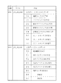
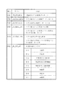
図7において、出力ポート3では、D0〜D3ビットからは、左リール31のモータ32の各φ0〜φ3信号が出力される。本実施形態のモータ32は、1−2相励磁によりリール31を回転するように構成されており、φ0〜φ3の4相の励磁の組合せでリール31を駆動するようにしているため、各相の信号がそれぞれ所定のビットから出力される。
In FIG. 7, at the
また、D6ビットからは、ブロッカ47の信号が出力される。さらにまた、D7ビットからは、ホッパーモータ36の駆動信号が出力される。
ここで、ブロッカ47は、ブロッカの信号が「1」(オン)であるときは、メダル投入口44とホッパー35aとを連結するメダル通路を形成し、メダルの受付けを許可する。これに対し、「0」(オフ)であるときは、メダル投入口44と払出し口14とを連結する通路(返却通路)を形成し、メダルの受付けを不許可とする。
そして、たとえばブロッカ47の駆動時には、割込み処理によって、出力ポート3のD6ビットからブロッカ信号を出力する。
Also, the signal of the blocker 47 is output from the D6 bit. Furthermore, a drive signal for the hopper motor 36 is output from the D7 bit.
Here, when the signal of the blocker is “1” (ON), the blocker 47 forms a medal passage connecting the
For example, when the blocker 47 is driven, a blocker signal is output from the D6 bit of the
出力ポート4のD0〜D3ビットからは、中リール31のモータ32の各φ0〜φ3信号が出力される。同様に、出力ポート5のD0〜D3ビットからは、右リール31のモータ32の各φ0〜φ3信号が出力される。
また、出力ポート4のD5〜D7ビットからは、状態表示LED73中、1枚〜3枚投入表示LED73e〜73gの信号が出力される。
From the D0 to D3 bits of the
Further, from the D5 to D7 bits of the
さらにまた、出力ポート6からは、外部集中端子板100への外部信号が出力され、本実施形態では、外部信号1〜5、メダル払出し信号、及びメダル投入(ベット)信号が出力される。
ここで、「外部信号」とは、外部集中端子板100を介してスロットマシン10の外部(ホールコンピュータや、ホールに設置されているデータカウンタ等)に出力するための信号である。本実施形態では、ART発動(初当たり)を示す外部信号1、ART継続を示す外部信号2、ARTの開始時から終了時までを示す外部信号3、スロットマシン10で生じたエラーや電源断が発生したこと等を示す外部信号4、スロットマシン10のフロントドアの開放を示す外部信号5を設けている。
Furthermore, an external signal to the external
Here, the “external signal” is a signal to be output to the outside of the slot machine 10 (a hall computer, a data counter installed in the hall, etc.) via the external
ただし、これに限らず、外部信号1を1BB遊技中を示す信号としたり、外部信号2を特定のRT状態と定めること等も可能であり、外部信号1〜3は、必ずしもARTに限られるものではない。
これらの出力信号の詳細については、後述するが、本実施形態では、出力ポート6から出力される信号がBレジスタに記憶され、「外部出力信号データ」となる。
However, the present invention is not limited to this, and the
Although details of these output signals will be described later, in this embodiment, a signal output from the
次に、入力ポート0〜2から入力された信号に基づいて生成するレベルデータ、立ち上がりデータ、及び立ち上がりデータについて説明する。
図6に示すように、入力ポート0のD0〜D7(ただし、D4を除く)には、正又は負の信号が入力されるが、入力ポート0に入力された信号を取得した後、正論理又は負論理に変換(演算)した後のデータが、入力ポート0レベルデータとして記憶される。たとえば、入力ポート0において、D0、D1、D3ビットには、操作時には負の信号が入力され、入力された信号が「負」の場合は「1」、「正」の場合は「0」となるように演算する。
Next, level data, rising data, and rising data generated based on signals input from the
As shown in FIG. 6, positive or negative signals are input to D0 to D7 (except D4) of the
一方、入力ポート0において、D2、D5、D6、D7ビットには、操作時には正の信号が入力されるので、入力された信号が「正」の場合は「1」、「負」の場合は「0」となるように演算する。
On the other hand, in the
上記の論理変換処理をより具体的に説明する。
まず、入力ポート0〜2にそれぞれ入力された論理を統一するために、定義データ(ROMに記憶されているデータ)に相当する負論理ビットを設ける。たとえば、入力ポート0の負論理ビットは、図6に記載したように、「00001011」である。
そして、入力ポート0に信号が入力されると仮定する。ここでは、1ベットスイッチ40aがオンにされたものとする。1ベットスイッチ信号は、オンのときは負の信号が入力されるので、入力される信号は「0」である。また、入力ポート0における他のスイッチは操作されないものとすると、精算スイッチ信号(D0ビット)及びスタートスイッチ信号(D3ビット)は「1」、その他は「0」であるので、
入力データ:00001001
となる。
この入力データは、MPU内の所定のレジスタ(たとえばAレジスタ)に記憶される。
The above logical conversion process will be described more specifically.
First, in order to unify the logics respectively input to the
It is assumed that a signal is input to the
Input data: 00000101
It becomes.
This input data is stored in a predetermined register (for example, A register) in the MPU.
次に、上記入力データと、定義データに相当する入力ポート0負論理ビット「00001011」とを排他的論理和(XOR;エクスクルーシブオア)による論理演算を行う。これにより、
00001001:入力データ
00001011:入力ポート0負論理ビット
00000010:演算後データ
となり、操作されたスイッチである1ベットスイッチ40aに係るデータ(D1ビット)のみが「1」となる。
上記のように演算することで、1ベットスイッチ40aのみが操作されたことを検知することができる。
この演算後データ、すなわち「00000010」が、当該割込み時における「入力ポート0レベルデータ」となる。
Next, a logical operation by exclusive OR (XOR) is performed on the input data and the
00001001: Input data 00001011:
By calculating as described above, it is possible to detect that only the 1-bet switch 40a has been operated.
The post-computation data, that is, “00000010” becomes “
また、入力ポート0のD4ビットのように未使用ビットを有する場合には、この未使用ビットに対応するデータを確実に「0」にするために、上記の演算後データと定義データ「11101111」(未使用ビットのみを「0」としたデータ)とを「AND」演算(論理積)してもよい。これにより、
00000010:演算後データ
11101111:定義データ
00000010:演算後データ(AND後)
となる。
なお、未使用ビットを有さないときは、最初の演算後データの算出までで十分であり、演算後データ(AND後)の算出は不要である。また、未使用ビットを有する場合であっても、最初の演算後データの算出で終了することも可能であり、演算後データ(AND後)の算出は、ノイズをより確実に除去するために行われる。
In addition, when there is an unused bit such as the D4 bit of the
00000010: Data after operation 11101111: Definition data 00000010: Data after operation (after AND)
It becomes.
When there are no unused bits, calculation up to the first post-computation data is sufficient, and post-computation data (after AND) need not be computed. In addition, even if there are unused bits, it is possible to end the calculation after the first calculation data, and the calculation after calculation (after AND) is performed in order to more surely remove noise. Is called.
以上のようにして、一割込み処理時に、入力ポート0〜2の信号に基づいて、入力ポート0レベルデータ、入力ポート1レベルデータ、入力ポート2レベルデータを作成する。
入力ポート1レベルデータは、実際に入力された信号と、図6に示す入力ポート1負論理ビット「00010001」とを排他的論理和(XOR)による演算を実行したものである。
また、入力ポート2レベルデータは、実際に入力された信号と、図6に示す入力ポート2負論理ビット「00101111」とを排他的論理和(XOR)による演算を実行したものである。
作成された入力ポート0レベルデータ〜入力ポート2レベルデータは、RWM61内の所定の番地(後述)に記憶される。
As described above, the
The
The
The created
さらに、本実施形態では、入力ポート0レベルデータから、入力ポート0立ち上がりデータを作成する。また、入力ポート1レベルデータから、入力ポート1立ち上がりデータ及び入力ポート1立ち下がりデータを作成する。
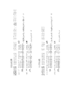
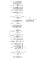
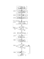
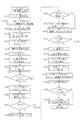
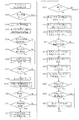
図8は、入力ポート1の立ち上がりデータ及び立ち下がりデータを作成する演算例を示す図である。
Furthermore, in this embodiment,
FIG. 8 is a diagram illustrating a calculation example for creating rising data and falling data of the
図8において、前回割込み時の入力ポート1レベルデータ(データB0)が「00000010」(D1ビットのドアスイッチ信号のみがオン)であり、今回割込み時の入力ポート1レベルデータ(データA0)が「00000110」(D1ビットのドアスイッチ信号及びD2ビットの設定ドアスイッチ信号がオン)となった例である。したがって、設定ドアスイッチ信号について立ち上がりを有する例である。
In FIG. 8, the
この場合、図8に示すように、まず、データA0(今回割込み時のレベルデータ)とデータB0(前回割込み時のレベルデータ)とを排他的論理和(XOR)による演算を実行する。その演算結果をデータC0とすると、データC0は、入力ポート1の変化ビットを示すデータとなる。
次に、データA0(今回割込み時のレベルデータ)とデータC0(変化ビットを示すデータ)とを論理積(AND)により演算を実行する。これにより作成されるデータD0が、入力ポート1立ち上がりデータとなる。
In this case, as shown in FIG. 8, first, an operation using exclusive OR (XOR) is performed on data A0 (level data at the time of the current interruption) and data B0 (level data at the time of the previous interruption). When the calculation result is data C0, the data C0 is data indicating a change bit of the
Next, an operation is performed on the data A0 (level data at the time of the current interruption) and the data C0 (data indicating the change bit) by AND (AND). The data D0 thus created becomes the
また、立ち下がりを求める場合には、以下のように演算を行う。
前回割込み時の入力ポート1レベルデータ(データB1)が「00000010」(D1ビットのドアスイッチ信号のみがオン)であり、今回割込み時の入力ポート1レベルデータ(データA1)が「00000000」(全ビットがオフ)となった例である。したがって、ドアスイッチ信号について立ち下がりを有する例である。
In addition, when calculating the fall, the following calculation is performed.
The
この場合、まず、データA1(今回割込み時のレベルデータ)とデータB1(前回割込み時のレベルデータ)とを排他的論理和(XOR)による演算を実行する。その演算結果をデータC1とすると、データC1は、上記のデータC0と同様に、入力ポート1の変化ビットを示すデータとなる。
次に、データB1(前回回割込み時のレベルデータ)とデータC1(変化ビットを示すデータ)とを論理積(AND)により演算を実行する。これにより作成されるデータD1が、入力ポート1立ち下がりデータとなる。
In this case, first, an operation by exclusive OR (XOR) is performed on the data A1 (level data at the time of the current interruption) and the data B1 (level data at the time of the previous interruption). Assuming that the operation result is data C1, the data C1 is data indicating a change bit of the
Next, an operation is performed on the data B1 (level data at the previous interruption) and the data C1 (data indicating the change bit) by AND (AND). The data D1 created thereby becomes the
さらに、上記の例では、入力ポートのデータを一割込みで1回取得した例を示したが、ノイズやチャタリング防止のために、一割込み内で複数回、入力ポートの信号を取得してもよい。
たとえば、入力ポート0を例にあげると、一割込み内で、2回、入力ポート0のデータを取得する。なお、データを2回取得する場合の時間間隔は任意であるが、たとえば1回目のデータ取得時から50μS(マイクロ秒)経過後に2回目のデータを取得することが挙げられる。
Furthermore, in the above example, the input port data is acquired once per interrupt. However, in order to prevent noise and chattering, the input port signal may be acquired multiple times within one interrupt. .
For example, taking
具体的に、1ベットスイッチ40aが操作されたことにより、D1ビットがオンになったとき、
00000100:取得データ1回目(正常)
00000100:取得データ2回目(正常)
であったと仮定する。なお、上記例では、1回目及び2回目のいずれも正常なデータを取得し、両データに変化がない例を示している。そして、これら2つのデータを論理積(AND)による演算を実行する。その結果、
00000100:AND演算後
となる。このAND演算後のデータを当該割込み処理時におけるレベルデータとする。
Specifically, when the D1 bit is turned on by operating the 1-bet switch 40a,
00000100: Acquisition data first time (normal)
00000100: Acquisition data second time (normal)
Suppose that In the above example, normal data is acquired both in the first time and the second time, and there is no change in both data. Then, an arithmetic operation using AND of these two data is executed. as a result,
00000100: After AND operation. The data after the AND operation is set as level data at the time of the interrupt processing.
これに対し、ノイズやチャタリングが発生し、2回の取得データが異常となった場合には、以下のようになる。たとえば、2回目のデータ取得時に3ベットスイッチ40bの信号を誤検知し、「1」となったときは、
00000100:取得データ1回目(正常)
00000110:取得データ2回目(異常)
となる。そして、両データを上記のように論理積(AND)による演算を実行すると、
00000100:AND演算後
となり、上記と同じ結果を得る。すなわち、AND演算を実行することで、取得データ2回目のD1ビットを「0」にすることができ、これによってノイズやチャタリング等を防止することができる。
On the other hand, when noise or chattering occurs and the acquired data becomes abnormal twice, the following occurs. For example, when the signal of the 3-bet switch 40b is erroneously detected at the second data acquisition and becomes “1”,
00000100: Acquisition data first time (normal)
00000110: Acquisition data second time (abnormal)
It becomes. And, when both data are subjected to a logical product (AND) operation as described above,
0000100: After AND operation, the same result as above is obtained. That is, by performing the AND operation, the D1 bit of the second acquisition data can be set to “0”, thereby preventing noise, chattering, and the like.
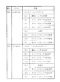
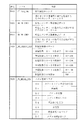
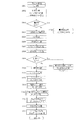
図9〜図17は、RWM61に記憶されるデータの格納番地とその内容を示す図である。なお、図9〜図17で示したデータは、本実施形態の説明で用いるためのデータであり、RWM61に記憶されるデータは、これらのデータに限られるものではない。
図9において、番地「F008」の「_PT_IN0_OLD 」は、入力ポート0レベルデータの記憶領域である。一割込み処理ごとに、入力ポート0からの入力信号が読み込まれ、上述したように演算された後、レベルデータが更新されていく。
番地「F009」の「_PT_IN0_UP」は、入力ポート0立ち上がりデータの記憶領域である。入力ポート0レベルデータの更新ごとに演算され、入力ポート0立ち上がりデータも更新されていく。
9 to 17 are diagrams showing the storage addresses of the data stored in the RWM 61 and the contents thereof. The data shown in FIGS. 9 to 17 is data used in the description of the present embodiment, and the data stored in the RWM 61 is not limited to these data.
In FIG. 9, “_PT_IN0_OLD” of the address “F008” is a storage area for
“_PT_IN0_UP” of the address “F009” is a storage area for
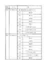
図10において、番地「F00A」の「_PT_IN1_OLD 」は、入力ポート1レベルデータの記憶領域である。一割込み処理ごとに、入力ポート1からの入力信号が読み込まれ、上述したように演算された後、データが更新されていく。
また、番地「F00B」の「_PT_IN1_UP」は、入力ポート1立ち上がりデータの記憶領域である。入力ポート1レベルデータの更新ごとに演算され、入力ポート1立ち上がりデータも更新されていく。
In FIG. 10, “_PT_IN1_OLD” of the address “F00A” is a storage area for
In addition, “_PT_IN1_UP” of the address “F00B” is a storage area for
さらにまた、図11において、番地「F00C」の「_PT_IN1_DOWN」は、入力ポート1立ち下がりデータの記憶領域である。入力ポート1レベルデータの更新ごとに演算され、入力ポート1立ち下がりデータも更新されていく。
また、番地「F00D」の「_PT_IN2_OLD 」は、入力ポート2レベルデータの記憶領域である。一割込み処理ごとに、入力ポート2からの入力信号が読み込まれ、上述したように演算された後、データが更新されていく。
Furthermore, in FIG. 11, “_PT_IN1_DOWN” of the address “F00C” is a storage area for the falling data of the
Further, “_PT_IN2_OLD” of the address “F00D” is a storage area for the
図12において、番地「F00F」の「_FL_ERROR_INF 」は、特定情報フラグのデータ記憶領域である。ここで、特定情報フラグは、本実施形態では、ドアスイッチ情報(D1)、設定ドアスイッチ情報(D2)、設定キースイッチ情報(D3)、設定/リセットスイッチ情報(D4)、電源断復帰時送信ビット(D6)から構成されている。
ドアスイッチ情報(D1)、設定ドアスイッチ情報(D2)、設定キースイッチ情報(D3)、及び設定/リセットスイッチ情報(D4)は、入力ポート1レベルデータの各ビットと対応している。そして、たとえばドアスイッチ16のオンが検知されると、入力ポート1レベルデータのD1ビットがオン(「1」)となるが、これに併せて、特定情報フラグのD1ビットがオン(「1」)となる。設定キースイッチ情報(D3)、及び設定/リセットスイッチ情報(D4)についても同様である。
In FIG. 12, “_FL_ERROR_INF” of the address “F00F” is a data storage area of the specific information flag. Here, in this embodiment, the specific information flag is door switch information (D1), setting door switch information (D2), setting key switch information (D3), setting / reset switch information (D4), and transmission at power-off recovery. It consists of bit (D6).
The door switch information (D1), the setting door switch information (D2), the setting key switch information (D3), and the setting / reset switch information (D4) correspond to each bit of the
また、D6ビットの「電源復帰時送信ビット」は、電源断からの復帰を検知した後、所定時間を経過するまでの間、オン(「1」)となるフラグである。特定情報フラグは、電源断からの復帰時から所定時間を経過したか否かと、上述の設定変更に関するスイッチのオン/オフの状況とを同時に判断するために、1フラグ内(1バイトデータ内)に、これらの情報を記憶している。したがって、特定情報フラグにアクセスして各ビットのオン/オフを判断すれば、設定変更に係るスイッチのオン/オフと、電源断からの復帰後所定時間を経過したか否かを同時に判断可能となる。 The D6 bit “transmission bit at power recovery” is a flag that is on (“1”) until a predetermined time elapses after detection of recovery from power failure. The specific information flag is in one flag (in one byte data) in order to simultaneously determine whether or not a predetermined time has elapsed since the return from power-off and the on / off state of the switch relating to the above-described setting change. In addition, these pieces of information are stored. Therefore, by accessing the specific information flag and determining whether each bit is on or off, it is possible to simultaneously determine whether the switch related to the setting change is on or off and whether or not a predetermined time has elapsed after the return from power-off. Become.
また、番地「F010」の「_FL_IN_ABNML」は、異常入力フラグのデータ記憶領域であり、本実施形態では、D4〜D6ビットのデータは、それぞれ通路センサ46の滞留異常が生じたとき、投入センサ2(44b)の異常入力が生じたとき、及び払出しセンサ37の異常入力が生じたときにオンとなる。
Further, “_FL_IN_ABNML” of the address “F010” is a data storage area of the abnormal input flag. In this embodiment, when the dwelling abnormality of the passage sensor 46 occurs in the D4 to D6 bit data, the
図13において、番地「F012」の「_CT_SEN_CHK 」は、投入監視カウンタのデータ記憶領域であり、通路センサ46の通過異常検出を監視するものである。本実施形態では、入力ポート1立ち上がりデータ(番地「F00B」の「_PT_IN1_UP」)において、通路センサ46(D0ビット)が「1」であるときに「1」加算され(後述する図66のステップS908)、メダルが正常に通過したと判断したときに「1」減算される(後述する図52のステップS250)。また、このカウント値を、複数遊技にわたる累積値としないようにするため、後述する図46のステップS165においてクリアする。
また、番地「F013」の「_WK_H0_CHK1 」は、払出しセンサ1(37a)異常検出データの記憶領域であり、払出しセンサ1(37a)への異常入力を検出するためのデータである。その範囲は、「0」〜「4」をとり、後述するように、発生したエラー番号を特定するときに用いられる。
In FIG. 13, “_CT_SEN_CHK” of the address “F012” is a data storage area of the input monitoring counter, and monitors passage abnormality detection of the passage sensor 46. In this embodiment, “1” is added to the
Further, “_WK_H0_CHK1” of the address “F013” is a storage area for the payout sensor 1 (37a) abnormality detection data, and is data for detecting an abnormal input to the payout sensor 1 (37a). The range is “0” to “4”, and is used when specifying the error number that occurred as will be described later.
番地「F014」の「_WK_H0_CHK2 」は、払出しセンサ2(37b)異常検出データの記憶領域であり、払出しセンサ2(37b)への異常入力を検出するためのデータである。上記の払出しセンサ1(37a)異常検出データと同様に、「0」〜「4」の範囲をとり、発生したエラー番号を特定するときに用いられる。 “_WK_H0_CHK2” of the address “F014” is a storage area for the payout sensor 2 (37b) abnormality detection data, and is data for detecting an abnormal input to the payout sensor 2 (37b). Similar to the above-described payout sensor 1 (37a) abnormality detection data, it is used when taking the range of “0” to “4” and specifying the generated error number.
さらにまた、番地「F019」の「_NB_CREDIT_LED」は、貯留枚数表示データの記憶領域であり、上述した貯留数表示LED71にその時点での貯留枚数を表示するためのデータを記憶している。ここで、本実施形態では、データそのものは16進数(H)であるが、貯留枚数を10進数に換算した値を記憶する。たとえば、表示すべき貯留枚数が「29」であるとき、「29(H)」という値を記憶する。換言すると、番地「F019」には、「00101001(B)」を記憶する。これにより、番地「F019」のD0〜D3の下位4ビットは、貯留枚数の下位桁(本例では「9」)を表示するために使用し、D4〜D7の上位4ビットは、貯留枚数の上位桁(本例では「2」)を表示するためのデータとして記憶している。なお、本実施形態では、貯留枚数の上限値は「50」であるので、記憶されるデータ値は、「0」〜「50」の範囲となる。
Furthermore, “_NB_CREDIT_LED” of the address “F019” is a storage area of the stored number display data, and stores the data for displaying the stored number at that time in the stored
さらに、番地「F01B」の「_FL_MEDAL_STS 」は、メダル管理フラグのデータ記憶領域である。このメダル管理フラグは、主として状態表示LED73の点灯/消灯を制御するためのフラグである。メダル管理フラグにおいて、D0ビットは、スタートスイッチ41受付け状態を示し、スタートスイッチ41を受け付けているとき、すなわちスタートスイッチ41が操作可能であるとき(たとえばメダルがベットされ、遊技開始前の状態)に「1」となり、スタートスイッチ41の操作受付けが不可能状態であるとき(たとえばリール31の回転中)は「0」にされる。
D2ビットのブロッカ状態は、ブロッカ47がオンであるときは「1」となり、オフであるときは「0」にされるデータである。このD2ビットの値を判断することにより、現在のブロッカ47がどのような状態であるか(オンかオフか)を判断可能となる。
Further, “_FL_MEDAL_STS” of the address “F01B” is a data storage area of a medal management flag. This medal management flag is a flag for mainly controlling the turning on / off of the status display LED 73. In the medal management flag, the D0 bit indicates the
The blocker state of the D2 bit is data that is “1” when the blocker 47 is on and is “0” when it is off. By determining the value of this D2 bit, it is possible to determine what state the current blocker 47 is in (on or off).
D3ビットのリプレイ表示LEDは、リプレイが表示され、再遊技としてメダルが自動投入されるとき(図43のステップS144)に、「1」にされるデータである。このデータが「1」のときに、上述した状態表示LED73のうちのリプレイ表示LED73aが点灯する。また、再遊技による遊技が終了したとき(図39のステップS68)に、「0」にされるデータである。このデータが「0」のとき、リプレイ表示LED73aが消灯する。
D4ビットの精算表示LEDは、精算スイッチ43が操作され、貯留メダルを精算するとき(図57のステップS324)に、「1」にされるデータである。このデータが「1」のとき、上述した状態表示LED73のうちの精算表示LED73cが点灯する。また、貯留メダルの精算が終了したとき(図57のステップS326)に、「0」にされるデータである。
The D3-bit replay display LED is data that is set to “1” when a replay is displayed and a medal is automatically inserted as a replay (step S144 in FIG. 43). When this data is “1”, the replay display LED 73a of the above-described status display LEDs 73 is lit. Further, the data is set to “0” when the game by re-game is completed (step S68 in FIG. 39). When this data is “0”, the replay display LED 73a is turned off.
The D4-bit settlement display LED is data that is set to “1” when the settlement switch 43 is operated to settle the stored medal (step S324 in FIG. 57). When this data is “1”, the settlement display LED 73c of the above-described status display LEDs 73 is turned on. Further, the data is set to “0” when the settlement of the stored medal is completed (step S326 in FIG. 57).
このように、本実施形態では、最大50枚まで記憶可能な貯留メダルの精算を実行しているときに精算表示LED73cが点灯するように形成されているが、一度にベットメダルと貯留メダルとを精算するように形成されている場合には、ベット又は貯留メダルを精算するときに「1」にされるように(精算表示LED73cが点灯するように)形成されていることが好ましい。 As described above, in this embodiment, the adjustment display LED 73c is lit when the adjustment of the stored medals that can be stored up to 50 is executed. However, the bet medals and the stored medals are displayed at a time. When it is formed so as to be settled, it is preferably formed so as to be set to “1” when the bet or the stored medal is settled (so that the settlement display LED 73c is lit).
D6ビットの設定変更不可フラグは、設定変更が可能な状態であるときに「0」となり、それ以外は「1」となるデータである。本実施形態では、スタートスイッチ41が操作されて遊技が進行されたとき(図62のステップS433)に、「1」にされるデータであり、次遊技のメダル受付けが開始されたとき(図43のステップS136)に、「0」にされるデータである。設定変更に際しては、設定変更許可フラグの値が参照され、設定変更不可フラグが「1」であるときは設定変更は許可されない。ただし、設定変更不可フラグが「1」のときであっても復帰不可能エラー(たとえば、割込み処理ごとに判定される乱数の更新異常)と判断されたときは設定変更が許可され、設定変更に基づいて復帰不可能エラーを解除することが可能となる。
The D6 bit setting change disable flag is data that is “0” when the setting can be changed, and is “1” otherwise. In the present embodiment, when the
D7ビットのメダル限界設定判定は、ベットメダル枚数がメダル限界枚数に達しているときは「1」となり、メダル限界枚数に達していないときは「0」となるデータである。上述したように、限界枚数は、本実施形態では、通常遊技中は3枚、1BB遊技中は2枚に設定されており、これらの3枚又は2枚がメダル限界枚数である。したがって、たとえば通常遊技中において、ベットメダル枚数が0、1、又は2枚であるときはメダル限界枚数に達していないので「0」となり、3枚であるときはメダル限界枚数に達しているので「1」となる。 The D7-bit medal limit setting determination is data that is “1” when the bet medal number reaches the medal limit number, and is “0” when the medal limit number is not reached. As described above, in the present embodiment, the limit number is set to three during normal game and two during 1BB game, and these three or two are the medal limit number. Therefore, for example, in normal games, when the number of bet medals is 0, 1, or 2, the medal limit number is not reached, so it is “0”. When the number is 3, the medal limit number is reached. “1”.
図14において、番地「F01C」の「_FL_ACTION」は、作動状態フラグのデータ記憶領域であり、本実施形態では、D0ビットにリプレイ、D1ビットに1BBが割り当てられている。
たとえばリプレイが入賞したときは、リプレイの作動状態となり、遊技状態をセットするとき(図41のステップS124)に、D0ビットが「1」にされる。このD0ビットが「1」から「0」にされるのは、再遊技による遊技が終了したとき(図39のステップS68)である。
In FIG. 14, “_FL_ACTION” of the address “F01C” is an operation state flag data storage area, and in this embodiment, replay is assigned to the D0 bit and 1BB is assigned to the D1 bit.
For example, when a replay is won, the replay is activated, and the D0 bit is set to “1” when the game state is set (step S124 in FIG. 41). The D0 bit is changed from “1” to “0” when the game by re-game is finished (step S68 in FIG. 39).
番地「F023」の「_PT_BLK_HPM 」は、ブロッカ信号及びホッパーモータ駆動信号のデータの記憶領域であり、ブロッカ信号としてD6ビット、ホッパーモータ駆動信号としてD7ビットが用いられる(D0〜D5ビットは未使用)。ブロッカ47をオンにするときは、D6ビットが「1」となり、ホッパーモータ36をオンにするときはD7ビットが「1」にされる。より具体的には、メイン処理内で番地「F023」を更新し、割込み処理内で番地「F023」のデータに基づいて出力ポート3のデータを生成し、ブロッカ47を制御している。
“_PT_BLK_HPM” of the address “F023” is a data storage area for the blocker signal and the hopper motor drive signal, and uses the D6 bit as the blocker signal and the D7 bit as the hopper motor drive signal (D0 to D5 bits are not used). . When the blocker 47 is turned on, the D6 bit is “1”, and when the hopper motor 36 is turned on, the D7 bit is set to “1”. More specifically, the address “F023” is updated in the main process, the data of the
図15において、番地「F025」の「_PT_MEDAL_LED 」は、投入枚数表示LEDデータの記憶領域であり、D5〜D7ビットにそれぞれ3枚〜1枚投入表示LED73g〜73eが割り当てられている。たとえば、D7ビットのみが「1」であるときは、1枚投入表示LED73eのみが点灯するように制御される。また、D7及びD6ビットが「1」であるときは、1枚投入表示LED73e及び2枚投入表示LED73fが点灯するように制御される。 In FIG. 15, “_PT_MEDAL_LED” of the address “F025” is a storage area of inserted sheet number display LED data, and 3 to 1 sheet insertion display LEDs 73g to 73e are assigned to the D5 to D7 bits, respectively. For example, when only the D7 bit is “1”, control is performed so that only the single-load display LED 73e is lit. Further, when the D7 and D6 bits are “1”, the one-sheet insertion display LED 73e and the two-sheet insertion display LED 73f are controlled to be lit.
番地「F027」の「_PT_MEDAL_IO」は、メダル信号データの記憶領域であり、D5ビットにメダル払出し信号、D6ビットにメダル投入(ベット)信号が割り当てられている。このビットの割り当ては、出力ポート6(図7)のメダル払出し信号及びメダル投入(ベット)信号の割り当てビットと同一になるように設定されている。メダル払出し信号は、外部にメダル払出し信号を出力するとき(送信しているとき)にオンとなる。同様に、メダル投入信号は、外部にメダル投入(ベット)信号を出力するときにオンとなる。
なお、本実施形態において、メダル投入信号は、ベットメダル枚数データ(何枚ベットされて遊技が開始されたか)を外部に送信するものであり、貯留枚数データは含まれない。
“_PT_MEDAL_IO” of the address “F027” is a storage area for medal signal data, and a medal payout signal is assigned to the D5 bit and a medal insertion (bet) signal is assigned to the D6 bit. The bit allocation is set to be the same as the allocation bits of the medal payout signal and the medal insertion (bet) signal of the output port 6 (FIG. 7). The medal payout signal is turned on when the medal payout signal is output (transmitted) to the outside. Similarly, the medal insertion signal is turned on when a medal insertion (bet) signal is output to the outside.
In the present embodiment, the medal insertion signal is for transmitting bet medal number data (how many bets have been placed and the game has started) to the outside, and does not include the stored number data.
図16において、番地「F02A」の「_TM1_OUT_CNT」(外部信号出力時間)は、メダル投入信号及びメダル払出し信号の出力時間を計測するためのタイマ値の記憶領域である。本実施形態では、タイマ値が「0」になったと判断したときは、再度、タイマ値「46」にセットし、一割込みごとに「1」減算するカウントを継続する。
番地「F02F」の「_TM1_MDL_SENS 」は、投入センサ48a及び48bの異常入力検出を行うためのタイマ値の記憶領域である。本実施形態では、ブロッカ47がオフになったときに初期値として「224」をセットし、一割込みごとに「1」ずつ減算する。そして、詳細は後述するが、この値が「0」となったときに、投入センサ48a及び48bがメダルを検知しているときはエラーとする。
In FIG. 16, “_TM1_OUT_CNT” (external signal output time) of the address “F02A” is a timer value storage area for measuring the output time of the medal insertion signal and medal payout signal. In this embodiment, when it is determined that the timer value has become “0”, the timer value is set to “46” again, and the count for subtracting “1” for each interrupt is continued.
“_TM1_MDL_SENS” of the address “F02F” is a storage area of a timer value for detecting an abnormal input of the input sensors 48a and 48b. In this embodiment, when the blocker 47 is turned off, “224” is set as an initial value, and “1” is subtracted for each interrupt. As will be described in detail later, when this value is “0”, an error occurs when the insertion sensors 48a and 48b detect medals.
番地「F031」の「_TM1_CH_CHK 」は、通路センサ46の異常通過検出を行うためのタイマ値の記憶領域である。本実施形態では、通路センサ46の異常検出を開始するときに「200」の値をセットし、一割込みごとに「1」ずつ減算する。そして、「0」となったときでも通路センサ46がメダルを検知しているときはエラーとする。 “_TM1_CH_CHK” of the address “F031” is a storage area for a timer value for detecting abnormal passage of the passage sensor 46. In this embodiment, a value of “200” is set when abnormality detection of the passage sensor 46 is started, and “1” is subtracted for each interrupt. Even when “0” is obtained, an error is detected when the passage sensor 46 detects a medal.
番地「F032」の「_TM1_BLOFF_CHK」は、メダルセレクタ45とブロッカ47との間でメダルの挟み込みを防止するための時間を監視するタイマ値の記憶領域である。通路センサ46の立ち上がりデータを検知したときに、初期値として「45」をセットし、一割込みごとに「1」ずつ減算する。そして、この値が「0」となる前まではブロッカ47をオフからオンにしない。
番地「F033」の「_TM1_POWER_ON 」は、電断復帰時に外部信号4(出力ポート6のD1ビット)を出力する時間をカウントするタイマ値の記憶領域である。本実施形態では、電源断からの復帰を検知すると、この値の初期値として「136」をセットし、一割込みごとに「1」ずつ減算する。そして、この値が「0」になるまで、外部信号4を出力すると判断する。
“_TM1_BLOFF_CHK” of the address “F032” is a storage area of a timer value for monitoring the time for preventing the medal from being caught between the
“_TM1_POWER_ON” of the address “F033” is a storage area of a timer value for counting the time for outputting the external signal 4 (D1 bit of the output port 6) at the time of power failure recovery. In the present embodiment, when a return from power-off is detected, “136” is set as the initial value of this value, and “1” is subtracted for each interrupt. Then, it is determined that the
番地「F040」の「_FL_WIN 」は、図柄組合せ表示フラグの記憶領域であり、本実施形態では、D0ビットにリプレイ、D1ビットに1BBが割り当てられている。たとえばリプレイ図柄が停止したと判断したときは、D0ビットが「1」にされる。そして、このビットが「1」から「0」にされるのは、次遊技の遊技開始時(スタートスイッチ41の操作時)である。
“_FL_WIN” of the address “F040” is a symbol combination display flag storage area, and in this embodiment, replay is assigned to the D0 bit and 1BB is assigned to the D1 bit. For example, when it is determined that the replay symbol has stopped, the D0 bit is set to “1”. This bit is changed from “1” to “0” when the next game starts (when the
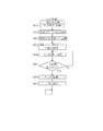
図17において、番地「F06C」の「_NB_REP_MEDAL 」は、自動投入枚数データ(リプレイ入賞時に自動ベットするメダル枚数を示すデータ)の記憶領域であり、本実施形態では「3」が記憶される。
番地「F06D」の「_NB_PLAY_MEDAL」は、メダルベット枚数データの記憶領域であり、本実施形態では、「0」〜「3」のいずれかが記憶される。
番地「F06E」の「_NB_PAY_MEDAL 」は、メダル払出し枚数データの記憶領域であり、本実施形態では、「0」〜「8」の値のいずれかが記憶される。なお、本実施形態では、1遊技におけるメダルの最大払出し枚数が8枚であるため、メダル払出し枚数データの最大値は「8」である。ただし、たとえば15枚払出し役を設けたときは、メダル払出し枚数データは、「0」〜「15」となる。
In FIG. 17, “_NB_REP_MEDAL” of the address “F06C” is a storage area of automatic insertion number data (data indicating the number of medals automatically bet upon replay winning), and “3” is stored in this embodiment.
“_NB_PLAY_MEDAL” of the address “F06D” is a storage area for medal bet number data, and in this embodiment, any one of “0” to “3” is stored.
“_NB_PAY_MEDAL” of the address “F06E” is a storage area of medal payout number data, and in the present embodiment, any value from “0” to “8” is stored. In the present embodiment, since the maximum payout number of medals in one game is 8, the maximum value of the medal payout number data is “8”. However, for example, when a 15-sheet payout combination is provided, the medal payout number data is “0” to “15”.
番地「F06F」の「_CT_MEDAL_IN」は、メダル投入(ベット)信号出力回数のデータ記憶領域であり、「0」〜「6」の値が記憶される。本実施形態では、このメダル投入信号出力回数は、メダルのベット枚数を信号として外部に出力する回数を示し、ベット枚数を2倍にした回数を出力する。したがって、本実施形態では、ベット枚数の最大値は「3」であるので、メダル投入信号出力回数の最大値は「6」となる。 “_CT_MEDAL_IN” of the address “F06F” is a data storage area of the number of medal insertion (bet) signal outputs, and values “0” to “6” are stored. In the present embodiment, the medal insertion signal output count indicates the number of times that the bet number of medals is output as a signal, and the number of times that the bet number is doubled is output. Accordingly, in the present embodiment, the maximum value of the bet number is “3”, and therefore the maximum value of the medal insertion signal output number is “6”.
番地「F070」の「_CT_MEDAL_OUT 」は、メダル払出し信号出力回数のデータ記憶領域であり、「0」〜「16」の値が記憶される。このメダル払出し信号出力回数は、メダル払出し枚数を信号として外部に出力する回数を示し、払出し枚数を2倍にした回数を出力する。したがって、本実施形態では、払出し枚数の最大値は「8」であるので、メダル払出し信号出力回数の最大値は「16」となる。上述したように、払出し枚数の最大値をたとえば「15」に設定した場合には、メダル払出し信号出力回数の最大値は「30」となる。 “_CT_MEDAL_OUT” of the address “F070” is a data storage area of the medal payout signal output count, and values “0” to “16” are stored. This medal payout signal output count indicates the number of times that the medal payout number is output to the outside as a signal, and outputs the number of times the payout number is doubled. Therefore, in the present embodiment, the maximum value of the number of payouts is “8”, so the maximum value of the medal payout signal output count is “16”. As described above, when the maximum value of the number of payouts is set to “15”, for example, the maximum value of the medal payout signal output count is “30”.
番地「F0E2」の「_FL_INF_OUT 」は、外部信号出力フラグの記憶領域であり、外部信号1〜3を出力するときに、それぞれ該当するビットが「1」となるデータである。これらの外部信号1〜3は、出力ポート6(図7)の外部信号1〜3と同一であり、これらの外部信号1〜3のビットの割り当ては、出力ポート6の外部信号1〜3のビットの割り当てと一致するように設定されている。
“_FL_INF_OUT” of the address “F0E2” is a storage area of the external signal output flag, and is data in which the corresponding bit is “1” when the
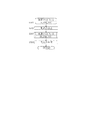
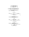
続いて、メダル信号(メダル投入信号、及びメダル払出し信号)について説明する。
図18(A)は、メダル信号の送信状態を説明するタイムチャートである。図18(A)に示すように、本実施形態では、メダル投入又は払出し信号は、メダル1枚につき、オン信号が1回送信される。たとえば、ベットメダルが3枚であるときは、メダル投入信号は、オン→オフ→オン→オフ→オン→オフとなる。同様に、たとえばメダル払出し枚数が1枚であるときは、メダル払出し信号は、オン→オフとなる。
Next, the medal signal (medal insertion signal and medal payout signal) will be described.
FIG. 18A is a time chart for explaining the transmission state of the medal signal. As shown in FIG. 18A, in this embodiment, the medal insertion or payout signal is transmitted once for each medal. For example, when there are three bet medals, the medal insertion signal is switched from on to off to on to off to on to off. Similarly, for example, when the medal payout number is 1, the medal payout signal changes from on to off.
また、図18(A)に示すように、本実施形態では、メダル信号を送信するときは、上述した外部信号出力時間としてカウント値が「0」(又は「46」の再セット)になったときにメダル信号をオンにし、再度、カウント値が「0」になるまで(すなわちメダル信号をオンにした後、46割込みをカウントするまで)メダル信号のオン状態を維持する。カウント値が「0」になる(割込み回数が「46」カウントされる)と、メダル信号をオフにし、再度、カウント値が「0」になるまで、すなわちメダル信号をオフにした後、46割込みをカウントするまでメダル信号のオフ状態を維持する。
本実施形態では、一割込み時間が2.235msであるので、46割込みを時間に換算すると、102.81(ms)(約100ms)となる。
上記のようなメダル信号の出力(オン/オフ)を、メダル枚数分だけ繰り返す。
As shown in FIG. 18A, in this embodiment, when the medal signal is transmitted, the count value becomes “0” (or “46” is reset) as the external signal output time described above. Sometimes, the medal signal is turned on, and the medal signal is kept on until the count value becomes “0” again (that is, after the medal signal is turned on, until 46 interrupts are counted). When the count value becomes “0” (the number of interruptions is counted as “46”), the medal signal is turned off, and until the count value becomes “0” again, that is, after the medal signal is turned off, 46 interrupts occur. The medal signal is kept off until the count is counted.
In this embodiment, since one interrupt time is 2.235 ms, when 46 interrupts are converted into time, it is 102.81 (ms) (about 100 ms).
The medal signal output (on / off) as described above is repeated for the number of medals.
図18(B)は、メダル払出し信号(メダル信号データ(_PT_MEDAL_IO)のD5ビット)とメダル払出し信号出力回数(_CT_MEDAL_OUT )との関係を示す図である。メダル払出し信号が「1」のとき、図18(A)のオン信号に相当し、「0」のとき、図18(A)のオフ信号に相当する。また、メダル払出し信号出力回数とは、オン又はオフになる回数を示す。したがって、本実施形態では、実際のメダル払出し枚数を2倍した値となる。 FIG. 18B is a diagram showing the relationship between the medal payout signal (D5 bit of medal signal data (_PT_MEDAL_IO)) and the medal payout signal output count (_CT_MEDAL_OUT). When the medal payout signal is “1”, it corresponds to an ON signal in FIG. 18A, and when it is “0”, it corresponds to an OFF signal in FIG. The medal payout signal output count indicates the number of times the medal payout signal is turned on or off. Therefore, in the present embodiment, the actual medal payout number is doubled.
図18(B)において、まず、最初(更新前)(図中、左端側)は、メダル払出し信号は「0」となっている例を示す。そして、3枚のメダルが払い出されたときは、メダル払出し信号出力回数は、「6」に更新される。
また、Cレジスタ値は、
メダル払出し信号出力回数の値が「0」より大きいとき:00100000(D5ビットが「1」)
メダル払出し信号出力回数の値が「0」のとき:00000000(D5ビットが「0」)
に設定される。
具体的には、後述する図72のステップS966でメダル払出し信号出力回数が「0」より大きいと判断したときはステップS968でCレジスタのD5ビットを「1」に設定する。
FIG. 18B shows an example in which the medal payout signal is “0” at the beginning (before update) (the left end side in the figure). When three medals are paid out, the medal payout signal output count is updated to “6”.
The C register value is
When the value of the medal payout signal output count is larger than “0”: 0010000 (D5 bit is “1”)
When the value of the medal payout signal output count is “0”: 00000000 (D5 bit is “0”)
Set to
Specifically, when it is determined in step S966 of FIG. 72 that will be described later that the medal payout signal output count is greater than “0”, the D5 bit of the C register is set to “1” in step S968.
したがって、上記例のように、メダル払出し信号出力回数が「6」に更新されると、Cレジスタ値のD5ビットは「1」となる。
次に、更新前メダル払出し信号と、CレジスタのD5ビット値とをXOR演算し、その値を更新後のメダル払出し信号とする。この例では、更新前メダル払出し信号が「0」、Cレジスタ値のD5ビットが「1」であるので、更新後メダル払出し信号は「1」となる。この更新後メダル払出し信号が「1」であるときは、図18(B)の下段図に示すようにオン信号となり、それが約100ms間継続される。
Accordingly, when the medal payout signal output count is updated to “6” as in the above example, the D5 bit of the C register value becomes “1”.
Next, an XOR operation is performed on the pre-update medal payout signal and the D5 bit value of the C register, and this value is used as the post-update medal payout signal. In this example, the pre-update medal payout signal is “0” and the D5 bit of the C register value is “1”, so the post-update medal payout signal is “1”. When the updated medal payout signal is “1”, the signal is turned on as shown in the lower diagram of FIG. 18B and is continued for about 100 ms.
次の更新では、更新前メダル払出し信号は、前回と異なり、「1」となる。また、1回、メダル払出し信号出力を実行したので、メダル払出し信号出力回数は、「6」から「1」を減算して「5」に更新される。よって、Cレジスタ値のD5ビットは「1」となり、更新後のメダル払出し信号は「0」となる。これにより、次の約100ms間は、メダル払出し信号はオフとなる。 In the next update, the pre-update medal payout signal is “1” unlike the previous update. Further, since the medal payout signal output is executed once, the medal payout signal output frequency is updated to “5” by subtracting “1” from “6”. Therefore, the D5 bit of the C register value is “1”, and the updated medal payout signal is “0”. As a result, the medal payout signal is turned off for the next approximately 100 ms.
以上のように、約100msごとに演算していくと、更新前のメダル払出し信号が「0」であるときは更新後のメダル払出し信号は「1」となり、更新前のメダル払出し信号が「1」であるときは更新後のメダル払出し信号は「0」となる。よって、メダル払出し信号の出力を終了するまでは、更新後のメダル払出し信号は、「0」と「1」とを繰り返し、図18(B)の下段に示すような波形となる。
また、メダル払出し信号出力回数は、最後には「0」となる。メダル払出し信号出力回数が「0」になると、Cレジスタ値のD5ビット値も「0」となる。よって、最終的には、更新前メダル払出し信号、メダル払出し信号出力回数、Cレジスタ値のD5ビット値、及び更新後メダル払出し信号のすべてが「0」となる(図18(B))。
As described above, when calculation is performed every about 100 ms, when the medal payout signal before update is “0”, the medal payout signal after update is “1”, and the medal payout signal before update is “1”. ", The updated medal payout signal is" 0 ". Accordingly, until the output of the medal payout signal is completed, the updated medal payout signal repeats “0” and “1” and has a waveform as shown in the lower part of FIG.
The medal payout signal output count is “0” at the end. When the medal payout signal output count becomes “0”, the D5 bit value of the C register value also becomes “0”. Therefore, finally, the pre-update medal payout signal, the medal payout signal output count, the D5 bit value of the C register value, and the post-update medal payout signal all become “0” (FIG. 18B).
以上のように、本実施形態では、メダル払出し信号出力回数(F070;_CT_MEDAL_OUT )として、メダル払出し枚数データ(F06E;_NB_PAY_MEDAL )(リプレイ入賞時はメダル投入枚数データ(F06D;_NB_PLAY_MEDAL))を2倍にした値を記憶する。
このことは、後述するメダル投入信号出力回数(F06F;_CT_MEDAL_IN)についても同様であり、メダル投入枚数データ(F06D;_NB_PLAY_MEDAL)を2倍にした値を記憶する。
このように設定したのは、「1」を示すデータと「0」を示すデータとをそれぞれ生成するためである。このようにすれば、前回のメダル払出し(又は投入)信号が「1」であるか否かという判断を行うことなく、単純な演算処理で正しいメダル払出し(又は投入)信号を生成することができるからである。
As described above, in this embodiment, the medal payout signal output count (F070; _CT_MEDAL_OUT) is doubled as the medal payout number data (F06E; _NB_PAY_MEDAL) (the medal insertion number data (F06D; _NB_PLAY_MEDAL) at the time of replay winning). Remember the value.
The same applies to the number of medal insertion signal outputs (F06F; _CT_MEDAL_IN), which will be described later, and a value obtained by doubling the medal insertion number data (F06D; _NB_PLAY_MEDAL) is stored.
The reason for this setting is to generate data indicating “1” and data indicating “0”. In this way, a correct medal payout (or insertion) signal can be generated by a simple arithmetic process without determining whether or not the previous medal payout (or insertion) signal is “1”. Because.
図19は、図18(B)に示したように、メダル払出し信号とメダル払出し信号出力回数との関係を示す図である。図19(A)は割込み禁止なし時を示し、図19(B)は割込み禁止あり時を示す。
図19(A)に示すように、更新前のメダル払出し信号が「1」、メダル払出し信号出力回数が「3」である場合においては、更新後のメダル払出し信号は、「0」となる。その後、次にメダル払出し信号が更新される前に、メダル払出し信号出力回数が「3」から「5」に更新されると仮定する。
FIG. 19 is a diagram showing the relationship between the medal payout signal and the medal payout signal output count as shown in FIG. FIG. 19A shows the time when interrupt is not prohibited, and FIG. 19B shows the time when interrupt is disabled.
As shown in FIG. 19A, when the medal payout signal before update is “1” and the medal payout signal output count is “3”, the updated medal payout signal is “0”. Thereafter, it is assumed that the medal payout signal output count is updated from “3” to “5” before the medal payout signal is updated next time.
図19(A)に示すように、まず、処理1により、メダル払出し信号出力回数「3」に、メダル1枚に相当する「2」を加算した値「5」を、Aレジスタに記憶する。次に、Aレジスタ値「5」を、メダル払出し信号出力回数として更新する前に、割込み処理が実行され、メダル払出し信号出力回数が「3」から「1」を減算する処理が実行されたものとする(後述する図72のステップS967)。この割込み処理後、Aレジスタ値「5」を、メダル払出し信号出力回数として更新したものとする(処理2)。
As shown in FIG. 19A, first, in
この場合、図19(A)に示すように、メダル払出し信号は「0」、メダル払出し信号出力回数が「5」となるので、Cレジスタ値のD5ビットは「1」、更新後のメダル払出し信号は「1」となる。
これにより、図18で説明したように、メダル払出し信号を出力し続けていったときに、最後には、メダル払出し信号出力回数が「0」、かつ、Cレジスタ値のD5ビットが「0」となるにもかかわらず、メダル払出し信号は「1」となる。したがって、これ以降は、メダル払出し信号が「1」のままとなり、「0」にはならなくなってしまう。
このような不都合は、後述する図72のステップS961において、「外部信号出力時間終了?」で「Yes」と判断されたとき(ステップS962〜S969の処理が実行されるとき)に起こり得る。
In this case, as shown in FIG. 19A, since the medal payout signal is “0” and the medal payout signal output count is “5”, the D5 bit of the C register value is “1”, and the updated medal payout The signal is “1”.
Accordingly, as described with reference to FIG. 18, when the medal payout signal is continuously output, finally, the medal payout signal output count is “0” and the D5 bit of the C register value is “0”. Nevertheless, the medal payout signal is “1”. Therefore, after this, the medal payout signal remains “1” and does not become “0”.
Such inconvenience may occur when “Yes” is determined in “External signal output time?” In step S961 of FIG. 72 described later (when the processing of steps S962 to S969 is executed).
上記のような不都合を回避するために、本実施形態では、メダル払出し信号出力回数の更新前後では、割込み禁止処理を実行する。その例が、図19(B)である。
図19(B)の例では、最初の段階では、同図(A)と同様に、メダル払出し信号が「1」、メダル払出し信号出力回数が「3」、Cレジスタ値のD5ビットが「1」となっている。この時点で、メダルが1枚払い出され、メダル払出し信号出力回数を更新しようとしたときは、割込みを禁止する(処理0)。
In order to avoid the inconvenience as described above, in the present embodiment, interrupt prohibition processing is executed before and after updating the medal payout signal output count. An example is shown in FIG.
In the example of FIG. 19B, at the first stage, as in FIG. 19A, the medal payout signal is “1”, the medal payout signal output count is “3”, and the D5 bit of the C register value is “1”. " At this time, when one medal is paid out and an attempt is made to update the number of medal payout signal outputs, interruption is prohibited (process 0).
次に、処理1により、メダル払出し信号出力回数「3」に、メダル1枚の払出しに相当する「1」の2倍値「2」を加算した「5」を、Aレジスタに記憶する。そして、Aレジスタ値「5」を、メダル払出し信号出力回数として更新する。
この更新後に、処理3により、禁止していた割込み処理を許可する。この許可により割込み処理が実行されると、メダル払出し信号出力回数「5」から「1」を減算する処理(ステップS967)が実行される。
Next, by processing 1, “5” obtained by adding a double value “2” of “1” corresponding to the payout of one medal to the medal payout signal output count “3” is stored in the A register. Then, the A register value “5” is updated as the medal payout signal output count.
After this update, the interrupt processing that has been prohibited is permitted by processing 3. When the interruption process is executed with this permission, a process of subtracting “1” from the medal payout signal output count “5” (step S967) is executed.
これにより、メダル払出し信号を出力し続けていったときに、最後には、メダル払出し信号出力回数が「0」、Cレジスタ値のD5ビットが「0」、かつメダル払出し信号が「0」となる。
以上のように、メダル払出し信号出力回数の更新前後で割込み処理を禁止し、メダル払出し信号出力回数の減算処理を禁止すれば、最後には、メダル払出し信号を「0」にすることができる。
なお、上述した割込み禁止処理は、図63のステップS461〜S463に相当する。
As a result, when the medal payout signal is continuously output, finally, the medal payout signal output count is “0”, the D5 bit of the C register value is “0”, and the medal payout signal is “0”. Become.
As described above, if the interruption process is prohibited before and after the medal payout signal output count is updated and the subtraction process of the medal payout signal output count is prohibited, the medal payout signal can be finally set to “0”.
Note that the interrupt prohibition process described above corresponds to steps S461 to S463 in FIG.
また、図18(B)及び図19は、メダル投入信号(メダル信号データ(_PT_MEDAL_IO)のD6ビット)、メダル投入信号出力回数(_CT_MEDAL_IN)についても同様に当てはまる。
具体的に説明すると、たとえば図18(B)において、最初(更新前)(図中、左端側)は、メダル投入信号は「0」となっている状態で、3枚のメダルが投入されると、メダル投入信号出力回数は、「6」に更新される。
また、Cレジスタ値は、
メダル投入信号出力回数の値が「0」より大きいとき:01000000(D6ビットが「1」)
メダル投入信号出力回数の値が「0」のとき:00000000(D6ビットが「0」)
に設定される。
この処理は、後述する図72のステップS963でメダル投入信号出力回数が「0」より大きいと判断したときはステップS965でCレジスタ値のD6ビットを「1」に設定する処理である。
18B and 19 similarly apply to the medal insertion signal (D6 bit of the medal signal data (_PT_MEDAL_IO)) and the medal insertion signal output count (_CT_MEDAL_IN).
Specifically, for example, in FIG. 18B, for the first time (before update) (the left end side in the figure), three medals are inserted while the medal insertion signal is “0”. The medal insertion signal output count is updated to “6”.
The C register value is
When the value of the medal insertion signal output count is larger than “0”: 01000000 (D6 bit is “1”)
When the value of the medal insertion signal output count is “0”: 00000000 (D6 bit is “0”)
Set to
This process is a process of setting the D6 bit of the C register value to “1” in step S965 when it is determined in step S963 in FIG. 72 described later that the number of medal insertion signal outputs is larger than “0”.
したがって、メダル投入信号出力回数が「6」に更新されると、Cレジスタ値のD6ビットは「1」となる。
次に、更新前メダル投入信号と、CレジスタのD6ビット値とをXOR演算し、その値を更新後のメダル投入信号とする。図18(B)の例では、更新前メダル投入信号が「0」、Cレジスタ値のD6ビットが「1」であるので、更新後メダル投入信号は「1」となる。この更新後メダル投入信号が「1」であるときは、図18(A)に示すようにオンとなり、それが約100ms間継続される。
Therefore, when the medal insertion signal output count is updated to “6”, the D6 bit of the C register value becomes “1”.
Next, an XOR operation is performed on the pre-update medal insertion signal and the D6 bit value of the C register, and the value is used as the updated medal insertion signal. In the example of FIG. 18B, since the pre-update medal insertion signal is “0” and the D6 bit of the C register value is “1”, the post-update medal insertion signal is “1”. When the updated medal insertion signal is “1”, it is turned on as shown in FIG. 18A, and this is continued for about 100 ms.
次の更新では、更新前メダル投入信号は、前回と異なり、「1」となる。また、1回、メダル投入信号出力を実行したので、メダル投入信号出力回数は、「6」から「1」を減算して「5」に更新される。よって、Cレジスタ値のD6ビットは「1」、更新後のメダル投入信号は「0」となる。これにより、次の約100ms間は、メダル投入信号はオフとなる。 In the next update, the medal insertion signal before update is “1” unlike the previous update. In addition, since the medal insertion signal output is executed once, the medal insertion signal output count is updated to “5” by subtracting “1” from “6”. Therefore, the D6 bit of the C register value is “1”, and the updated medal insertion signal is “0”. Thus, the medal insertion signal is turned off for the next approximately 100 ms.
以上のように、約100msごとに演算していくと、更新前のメダル投入信号が「0」であるときは更新後のメダル投入信号は「1」となり、更新前のメダル投入信号が「1」であるときは更新後のメダル投入信号は「0」となる。よって、メダル投入信号の出力を終了するまでは、更新後のメダル投入信号は、「0」と「1」とを繰り返し、図18(B)の下段に示すような波形となる。
また、メダル投入信号出力回数は、最後には「0」となる。メダル投入信号出力回数が「0」になると、Cレジスタ値のD6ビットも「0」となる。よって、最終的には、更新前メダル投入信号、メダル投入信号出力回数、Cレジスタ値のD6ビット、及び更新後メダル投入信号のすべてが「0」となる。
なお、メダル払出し時と同様に、メダル投入時にも、図19(B)のように割込み禁止処理を実行する。メダル投入時の割込み禁止処理は、図62のステップS442〜S444に相当する。
As described above, when calculation is performed every about 100 ms, when the medal insertion signal before update is “0”, the medal insertion signal after update is “1”, and the medal insertion signal before update is “1”. ", The updated medal insertion signal is" 0 ". Therefore, until the output of the medal insertion signal is completed, the updated medal insertion signal repeats “0” and “1” and has a waveform as shown in the lower part of FIG.
Further, the medal insertion signal output count is “0” at the end. When the medal insertion signal output count becomes “0”, the D6 bit of the C register value also becomes “0”. Therefore, finally, the pre-update medal insertion signal, the medal insertion signal output count, the D6 bit of the C register value, and the post-update medal insertion signal all become “0”.
As in the case of medal payout, interrupt prohibition processing is executed as shown in FIG. 19B when a medal is inserted. The interrupt prohibition process when a medal is inserted corresponds to steps S442 to S444 in FIG.
図20(A)、(B)は、それぞれ、メダル投入信号及びメダル払出し信号の送信タイミングを示すタイムチャートである。
上述したように、本実施形態では、メダル投入信号及びメダル払出し信号のいずれも、46割込み間、オンとなり、次に、46割込み間、オフとなる信号である。
外部信号出力時間は、カウントが開始されると、46割込み間(102.81ms)、割込み回数をカウントし、割込み回数のカウント値が「46」に到達すると、再度、値を「0」にリセットして、割込み回数のカウントを繰り返す。したがって、割込み回数「46」を繰り返すタイマである。
20A and 20B are time charts showing the transmission timing of the medal insertion signal and medal payout signal, respectively.
As described above, in the present embodiment, both the medal insertion signal and the medal payout signal are turned on during 46 interrupts, and then turned off during 46 interrupts.
The external signal output time is counted for 46 interrupts (102.81ms) when counting is started, and when the count value of the number of interrupts reaches “46”, the value is reset to “0” again. Then, the interrupt count is repeated. Therefore, the timer repeats the interrupt count “46”.
図20(A)において、メダルが3枚投入(ベット)されると、メダル投入信号を出力ポート6のD6ビットから出力する。上述したように、ベット枚数「3」のデータは2倍され、メダル投入信号出力回数は「6」となり、その数に対応するメダル投入信号が出力される。ここで、信号出力のタイミングは、外部信号出力時間の割込み回数のカウント値が「46」になった時である。したがって、メダル投入信号の送信準備が完了した後、次に外部信号出力時間の割込み回数のカウント値が「46」になった時が、送信開始タイミングとなる。
In FIG. 20A, when three medals are inserted (betted), a medal insertion signal is output from the D6 bit of the
そして、その信号は出力され続け、次に外部信号出力時間の割込み回数のカウント値が「46」になった時に、オンからオフにされる。また、メダル投入信号出力回数が「0」でないときは、次に外部信号出力時間の割込み回数のカウント値が「46」になった時に、オフからオンにされる。このようにして、外部信号出力時間の割込み回数のカウント値が「46」になった時が、信号のオン/オフの契機となる。 Then, the signal continues to be output, and when the count value of the number of interruptions of the external signal output time becomes “46”, it is turned off from on. When the medal insertion signal output count is not “0”, the count value of the interrupt count of the external signal output time is turned “46” when the external signal output time interrupt count is set to “46”. Thus, when the count value of the number of interruptions of the external signal output time becomes “46”, the signal is turned on / off.
図20(A)では、全リール31の停止時に、1枚役が入賞したときの例を示している。払出し枚数が「1」であるとき、上述したように、メダル払出し信号出力回数は、その値を2倍にした「2」となる。そして、メダル払出し信号の送信準備が完了した後、次に外部信号出力時間の割込み回数のカウント値が「46」になった時が、送信開始タイミングとなり、メダル払出し信号出力回数に対応するメダル払出し信号が出力される。出力信号がオンからオフ、及びオフからオンになるタイミングは、上記のメダル投入信号と同様である。
FIG. 20A shows an example in which one winning combination is won when all the
図20(B)は、メダル投入信号とメダル払出し信号との他の例を示している。図20(B)の例では、本実施形態では設けられていないが、15枚役(1遊技で払出し可能な最大枚数)が入賞したときのメダル払出し信号と次遊技との関係を示している。
全リール31が停止し、15枚役が入賞すると、メダル払出し信号出力回数として「30」が設定される(その直前のメダル払出し信号出力回数は「0」とする)。そして、上記と同様に、外部信号出力時間の割込み回数のカウント値が「46」になったタイミングで、メダル払出し信号の送信が開始される。上記のように、メダル払出し信号は、1つあたり約100msであるので、メダル払出し信号出力回数「30」に対応する時間は、約3秒となる。したがって、すべてのメダル払出し信号の送信が完了する前に、次遊技に移行し、さらに次遊技の全リール31が停止するまで遊技が進行する場合がある。
FIG. 20B shows another example of a medal insertion signal and a medal payout signal. In the example of FIG. 20B, although not provided in the present embodiment, the relationship between the medal payout signal and the next game when 15 winning combinations (the maximum number payable in one game) wins is shown. .
When all the
図20(B)の例では、メダル払出し信号出力回数が残り「13」となったときに3枚のメダルがベットされた例を示している。3枚のメダルがベットされると、メダル投入信号出力回数に「6」がセットされ、メダル投入信号がD6ビットから出力される。したがって、このメダル投入信号が出力されているときは、同時に、メダル払出し信号についてもD5ビットから出力されている。
また、本実施形態では、メダル投入信号の出力が完了する前であっても、遊技の開始が可能であるので、たとえば3ベットスイッチ40bが操作された直後にスタートスイッチ41が操作されたとき等は、メダル投入信号の出力完了前であってもリール31の回転が開始され、遊技が開始される。
The example of FIG. 20B shows an example in which three medals are bet when the remaining number of medal payout signal outputs is “13”. When three medals are bet, “6” is set as the number of medal insertion signal outputs, and the medal insertion signal is output from the D6 bit. Therefore, when this medal insertion signal is output, the medal payout signal is also output from the D5 bit.
Further, in the present embodiment, since the game can be started even before the output of the medal insertion signal is completed, for example, when the
そして、全リール31が停止したときに、図20(B)の例では、前遊技における15枚役の払出し信号の出力が未だ終了していない状態を示している。
さらに、この遊技では、8枚役が入賞したものとする。この場合、メダル払出し信号出力回数に、8枚の払出しに対応するメダル払出し信号出力回数「16」が加算される。この例では、メダル払出し信号出力回数が残り「2」のときに8枚払出し信号を受信し、メダル払出し信号出力回数(残り)が、「1+16=17」に更新された例を示している。
Then, when all the
Furthermore, in this game, it is assumed that eight winning combinations have won. In this case, the medal payout signal output count “16” corresponding to 8 payouts is added to the medal payout signal output count. In this example, when the remaining medal payout signal output count is “2”, 8 payout signals are received, and the medal payout signal output count (remaining) is updated to “1 + 16 = 17”.
図21は、出力ポート6のD2〜D4ビットから出力される外部信号1〜3を示すタイムチャートである。ART発動、ART継続、ART中であることを示す外部信号の出力タイミングとしては種々挙げられるが、本実施形態では、以下のように制御する。
本実施形態では、押し順正解カウンタ及び押し順不正解カウンタを備える。
押し順正解カウンタは、後述するベル当選時に正解押し順でストップスイッチ42が操作された回数をカウントする。また、連続して正解しないとカウンタは加算されない。
FIG. 21 is a time chart showing the
In this embodiment, a push order correct answer counter and a push order incorrect answer counter are provided.
The push order correct answer counter counts the number of times that the
たとえば、1回目のベル当選時に正解押し順でストップスイッチ42が操作されると、押し順正解カウンタは「+1」となる。次に、2回目のベル当選時に正解押し順でストップスイッチ42が操作されると、押し順正解カウンタは「+2」となる。しかし、2回目のベル当選時に不正解押し順でストップスイッチ42が操作されると、押し順正解カウンタのカウント値は「0」にクリアされる。このように、ベル当選時に、正解押し順でストップスイッチ42が操作されるごとに「+1」加算するが、ベル当選時に、不正解押し順でストップスイッチ42が操作されると「0」にクリアされる。
For example, if the
また、押し順正解カウンタは、ベル当選時に不正解押し順でストップスイッチ42が操作された回数をカウントする。また、連続して不正解にならないとカウンタは加算されない。たとえば、1回目のベル当選時に不正解押し順でストップスイッチ42が操作されると、押し順不正解カウンタは「+1」となる。次に、2回目のベル当選時に不正解押し順でストップスイッチ42が操作されると、押し順不正解カウンタは「+2」となる。しかし、2回目のベル当選時に正解押し順でストップスイッチ42が操作されると、「0」にクリアされる。
The push order correct answer counter counts the number of times the
これにより、ART遊技中は、遊技者の操作ミスによりベル当選時に不正解押し順でストップスイッチ42が操作されたとしても、2連続で操作ミスをしない限り、押し順不正解カウンタの値は「+2」にはならない。
さらにまた、非ART遊技中において、ベル当選時に、3回連続で、正解押し順となり、押し順正解カウンタが「+3」になることは極めて稀である。
Thus, during an ART game, even if the
Furthermore, in a non-ART game, when a bell is won, the correct answer is pushed in three consecutive times, and the push order correct answer counter becomes “+3” very rarely.
さらに、本実施形態では、ART中の遊技回数をカウントする遊技回数カウンタを備える。遊技回数カウンタは、押し順正解カウンタが「+1」になると、同時に「1」となり、押し順正解カウンタが「+3」になることなく「0」にクリアされたときは、同時に「0」にクリアされる。
押し順正解カウンタが「+3」になったときは、それ以降、ベル当選時の押し順正解/不正解にかかわらず、遊技ごとにカウント値を「+1」する。
Further, in the present embodiment, a game number counter for counting the number of games during ART is provided. The game number counter is cleared to “1” at the same time when the push order correct answer counter becomes “+1”, and cleared to “0” at the same time when the push order correct answer counter is cleared to “0” without becoming “+3”. Is done.
When the push order correct answer counter reaches “+3”, thereafter, the count value is incremented by “+1” for each game regardless of the push order correct answer / incorrect answer at the time of winning the bell.
ARTが開始されると、サブ制御基板80側で正解押し順が報知される。メイン制御基板60は、押し順正解カウンタが「+3」となったときは外部信号1及び3を出力する。
また、図21の例では、ARTは、1セットが50遊技からなり、当選等によって複数セットが継続可能に設定されている。本実施形態では、メイン制御基板60は、遊技回数カウンタが「50」となったときは、次のベル当選時に押し順正解カウンタが「+1」となったか否かを判断する。「+1」となったと判断したときは、外部信号1の出力を終了する。また、遊技回数カウンタが「50」となった後、押し順不正解カウンタが「+2」となったときは、外部信号1及び3の出力を終了する。
When ART is started, the correct answer push order is notified on the
In the example of FIG. 21, one set of ART consists of 50 games, and a plurality of sets are set to be able to be continued by winning or the like. In the present embodiment, when the game number counter reaches “50”, the
一方、ART継続を示す外部信号2は、押し順正解カウンタが「+3」となったときに、その時点からT1時間(たとえば1500ms)経過後に出力を開始する。そして、そして、遊技回数カウンタが「50」となった後、押し順正解カウンタが「+1」になるか、又は押し順不正解カウンタが「+2」になるまで出力を継続する。
図21の例では、ARTが3セット継続した例を示している。このような場合、遊技回数カウンタが「50」となった後、押し順正解カウンタが「+1」になったときは、その時点から外部信号2をオフにし、さらに、T2時間(たとえば1000ms)経過後に外部信号2の出力を再開する。
On the other hand, when the push order correct answer counter reaches “+3”, the
The example of FIG. 21 shows an example in which three sets of ART are continued. In such a case, after the game number counter becomes “50”, when the push order correct answer counter becomes “+1”, the
以上のようにして、図20及び図21に示すように、出力ポート6のD2〜D4ビットから外部信号1〜3(ART信号)が出力され、及びD5〜D6ビットからメダル投入又は払出し信号が出力される。
なお、上記例では、ベル当選時の正解押し順となった回数をカウントし、そのカウント値に基づいてARTに係る外部信号を送信した。しかし、これに限らず、後述するようにARTに移行したときはRT状態が移行(RT2に移行)するので、RT2となったときにART信号を送信するように構成してもよい。
また、出力ポート6(図7)に示すように、D0ビットからは外部信号5が出力され、D1ビットからは外部信号4が出力されるが、これらの信号出力については後述する。
As described above, as shown in FIGS. 20 and 21, the
In the above example, the number of times the correct answer was pressed when the bell was won was counted, and an external signal related to ART was transmitted based on the count value. However, the present invention is not limited to this, and as will be described later, the RT state is shifted (shifted to RT2) when the ART state is shifted to, so that an ART signal may be transmitted when the RT state is reached.
As shown in the output port 6 (FIG. 7), the
次に、メイン制御基板60の具体的構成について説明する。
図5に示すように、メイン制御基板60のメインCPU62は、以下の設定変更手段62a等を備える。なお、本実施形態における以下の各手段は例示であり、本実施形態で示した手段に限定されるものではない。
Next, a specific configuration of the
As shown in FIG. 5, the main CPU 62 of the
設定変更手段62aは、設定値を変更・決定する手段である。
ここで、設定値とは、遊技者の有利度、より具体的にはメダルの投入枚数に対する払出し枚数の期待値(遊技者が獲得できるメダル)の程度を定めるものであり、本実施形態では設定1〜設定6の6段階を設けている。
そして、設定値が高くなるほど、少なくとも一部の役の当選確率が高く設定される等、遊技者にとっての有利度が高くなるように設定している。
また、設定値が高くなるほど、ARTに移行する確率が高くなり、遊技者にとっての有利度が高くなるように設定している。
The setting changing means 62a is a means for changing / determining a setting value.
Here, the set value defines the degree of player's advantage, more specifically, the expected value of the payout number with respect to the number of inserted medals (medals that can be acquired by the player), and is set in this embodiment. 1 to setting 6 stages are provided.
The higher the set value, the higher the advantage for the player, such as the higher the winning probability of at least some of the combinations.
Further, the higher the set value is, the higher the probability of shifting to ART, and the higher the advantage for the player is set.
なお、ARTに移行する確率を高くすることのみに限られるものではなく、たとえばAT中の遊技回数や払出し枚数を上乗せする確率を高くしたり、ARTを継続する確率を高くしてもよい。 In addition, it is not restricted only to making the probability which transfers to ART high, For example, the probability of adding up the game frequency in AT and the number of payouts may be made high, and the probability of continuing ART may be made high.
設定値を設定・変更するには、電源スイッチ51、設定キースイッチ52、設定変更/リセットスイッチ53が用いられる。
本実施形態では、電源スイッチ51を一旦オフにし、電源断をした後に、設定キー挿入口に設定キーを差し込み、これを時計回りに90度回転させると、設定キースイッチ52がオンとなる。この状態で電源スイッチ51を再度オンにすると、設定変更中、すなわち設定変更モードになる。この場合、通常の立ち上げ処理は行われない。したがって、設定変更中にするためには、電源スイッチ51のオン/オフ操作が必要である。
In order to set / change the set value, a power switch 51, a setting key switch 52, and a setting change / reset switch 53 are used.
In the present embodiment, when the power switch 51 is turned off and the power is turned off, a setting key is inserted into the setting key insertion slot and rotated 90 degrees clockwise, so that the setting key switch 52 is turned on. When the power switch 51 is turned on again in this state, the setting is being changed, that is, the setting changing mode is entered. In this case, normal startup processing is not performed. Therefore, in order to change the setting, the power switch 51 needs to be turned on / off.
設定変更モードでは、設定変更手段62aは、設定値表示LED63に、現在の設定値を表示する。
また、設定変更手段62aは、設定変更/リセットスイッチ53が1回操作(オン)されるごとに、設定値の表示を、・・・→「1」→「2」→「3」→「4」→「5」→「6」→「1」→「2」→・・・と順次変化させる。
In the setting change mode, the setting changing means 62a displays the current setting value on the setting value display LED 63.
The setting change means 62a displays the setting value each time the setting change / reset switch 53 is operated (turned on): .fwdarw. "1" .fwdarw. "2" .fwdarw. "3" .fwdarw. "4" “→” 5 ”→“ 6 ”→“ 1 ”→“ 2 ”→...
さらに、設定変更手段62aは、スタートスイッチ41がオンにされると、このときに設定値表示LED63に表示していた数値で設定値を決定し、設定値が決定されたことを示す「0」を設定値表示LED63に表示する。
そして、設定変更手段62aは、設定キーを反時計回りに90度回転させて設定キースイッチ52をオフにすることで、決定した設定値をRWM61中の所定の記憶領域に記憶し、設定変更後の設定値で遊技が可能となる。
Further, when the
Then, the setting change means 62a rotates the setting key 90 degrees counterclockwise to turn off the setting key switch 52, thereby storing the determined setting value in a predetermined storage area in the RWM 61, and after the setting change It becomes possible to play with the set value.
なお、本実施形態では、設定キースイッチ52のオフの判定は、設定キースイッチ52の立下りデータに基づいて実行されるように構成されているが、設定キースイッチ52のオン/オフの状態に基づいて実行されるように構成してもよい。
また、設定キー挿入口から設定キーを抜かなければ設定変更後の設定値で遊技ができないように構成してもよい。
さらに、設定キーを反時計回りに90度回転させて設定キースイッチ52をオフにし、設定キー挿入口から設定キーを抜き、この状態で電源スイッチ51を一旦オフにした後に再度オンにしなければ、設定変更後の設定値で遊技ができないように構成してもよい。
In the present embodiment, the determination of the setting key switch 52 being turned off is performed based on the falling data of the setting key switch 52. However, the setting key switch 52 is turned on / off. You may comprise so that it may be performed based on.
Further, it may be configured so that the game cannot be performed with the setting value after the setting change unless the setting key is removed from the setting key insertion slot.
Further, if the setting key is rotated 90 degrees counterclockwise to turn off the setting key switch 52, the setting key is removed from the setting key insertion slot, and the power switch 51 is once turned off in this state and then not turned on again. You may comprise so that a game cannot be performed with the setting value after a setting change.
また、メダルがベットされていない状態で、かつ役抽選が行われていない状態(スタートスイッチ41の操作前)で、設定キーが設定キー挿入口に挿入され、設定キースイッチ52がオンにされると、「設定確認中」になる。すなわち、設定値を確認するだけの場合には、電源スイッチ51のオン/オフは不要である。設定確認中は、設定変更中と同様に、現時点での設定値が設定表示LED63に表示される。
さらにまた、設定キースイッチ52がオンにされた状態で、電源スイッチ51がオンにされると、リセット、すなわち初期化処理が行われる。この初期化処理については後述する。
In addition, in the state where no medals are bet and the part lottery is not performed (before the
Furthermore, when the power switch 51 is turned on while the setting key switch 52 is turned on, reset, that is, initialization processing is performed. This initialization process will be described later.
役抽選手段62bは、遊技ごとに、遊技開始時に、役の抽選を行うものである。
ここで、本実施形態の役、図柄の組合せ等について説明する。
図22は、本実施形態におけるリール31の図柄配列を示す図である。図22では、図柄番号を併せて図示している。たとえば、左リール31において、図柄番号16番の図柄は、「ベル」である。
The role lottery means 62b performs lottery for each game at the start of the game.
Here, the combination of the present embodiment, the combination of symbols, and the like will be described.
FIG. 22 is a diagram showing a symbol arrangement of the
図22に示すように、本実施形態では、各リール31は、16コマ(図柄)に等分割され、各コマに所定の図柄が表示されている。なお、スロットマシン10の仕様によっては、20コマや21コマであってもよい。
また、図23は、スロットマシン10のフロントカバー11に設けられた表示窓13(透明窓)と、各リール31の位置関係と、有効ラインとを示す図である。
As shown in FIG. 22, in this embodiment, each
FIG. 23 is a view showing the display window 13 (transparent window) provided on the
各リール31は、本実施形態では横方向に並列に3つ(左リール31、中リール31、及び右リール31)設けられている。さらに、各リール31は、表示窓13から、上下に連続する3図柄が見えるように配置されている。よって、スロットマシン10の表示窓13から、合計9個の図柄が見えるように配置されている。なお、各図柄の右下の数字は図柄番号を示している。
In this embodiment, three reels 31 (left
なお、本明細書では、図6中、左リール31の「スイカ(01番)」、中リール31の「リプレイ(16番)」、及び右リール31の「青7(14番)」の図柄が停止している位置を「上段」と称し、左リール31の「ベル(16番)」、中リール31の「ベル(15番)」、及び右リール31の「リプレイ(13番)」の図柄が停止している位置を「中段」と称し、左リール31の「リプレイ(15番)」、中リール31の「白7(14番)」、及び右リール31の「ベル(12番)」の図柄が停止している位置を「下段」と称する。
In this specification, in FIG. 6, “watermelon (01)” on the
さらにまた、図23に示すように、表示窓13から見える9個の図柄に対し、有効ラインが設定されている。
ここで、「有効ライン」とは、リール31の停止時における図柄の並びラインであって図柄の組合せを形成させる図柄組合せラインであり、かつ、いずれかの役に対応する図柄の組合せがそのラインに停止したときに、その役の入賞となるラインである。本実施形態では、図6に示すように、水平方向中段の有効ライン(1本)のみが定められ、他の図柄組合せラインは、全て無効ラインとなっている。
Furthermore, as shown in FIG. 23, effective lines are set for nine symbols visible from the
Here, the “effective line” is a symbol combination line that forms a symbol combination when the
たとえば、図23中、各リール31の上段を通過する図柄組合せラインや、左リール31の下段、中リール31の中段、及び右リール31の上段を通過する図柄組合せラインも考えられるが、このようなラインは、本実施形態では無効ラインとなっている。無効ラインは、図柄組合せラインのうち、有効ラインとして設定されないラインであって、いずれかの役に対応する図柄の組合せがそのラインに停止した場合であっても、その役に応じた利益の付与(メダルの払出し等)を行わないラインである。すなわち、無効ラインは、そもそも図柄の組合せの成立対象となっていないラインである。
For example, in FIG. 23, a symbol combination line passing through the upper stage of each
また、従来より、メダルのベット枚数に応じて有効ライン数が異なるスロットマシンが知られている。たとえば、メダルベット枚数が1枚のときは有効ラインは1本、メダルベット枚数が2枚のときは有効ライン数は3本、メダルベット枚数が3枚のときは有効ライン数は5本に設定すること等が挙げられる。これに対し、本実施形態では、遊技中は、3枚又は2枚のメダルをベットして遊技を行うとともに、すべての遊技において、常に水平方向中段の1本のみが有効ラインとなる。なお、有効ラインはメダルのベット枚数に応じて予め定められていればよい。 Conventionally, there are known slot machines in which the number of effective lines differs depending on the number of medals bet. For example, when the number of medal bets is one, one effective line is set, when the number of medal bets is two, the number of effective lines is three, and when the number of medal bets is three, the number of effective lines is set to five. And so on. On the other hand, in the present embodiment, during a game, three or two medals are bet and a game is played, and in all games, only one in the horizontal middle stage is always an effective line. The effective line may be determined in advance according to the number of medals bet.
図24〜図26は、本実施形態における役の種類、払出し枚数、及び図柄の組合せを示す図である。図24〜図26中、「役」の欄にかっこ書きで表示されたメダル枚数は、その役の入賞時の払出し枚数を示す。
また、たとえば図24のベル02aの場合には、ベル02aの図柄の組合せとして、「リプレイ」−「赤7」−「赤7」と、「リプレイ」−「赤7」−「BAR」の2種類を有するという意味である(他の役において、複数の図柄の組合せを有する場合も、同様の意味である。)。
24 to 26 are diagrams showing combinations of types of combinations, the number of payouts, and symbols in the present embodiment. In FIG. 24 to FIG. 26, the number of medals displayed in parentheses in the “Position” column indicates the number of payouts when winning the winning combination.
Further, for example, in the case of the bell 02a of FIG. 24, the combinations of the symbols of the bell 02a are 2 of "Replay"-"
本実施形態の役は、大別して、特別役、リプレイ、小役を有する。
そして、各役に対応する図柄の組合せ及び入賞時の払出し枚数等が定められている。すべてのリール31の停止時に、いずれかの役に対応する図柄の組合せが有効ラインに停止する(役が入賞する。以下同じ。)と、その役に対応する枚数のメダルが払い出される。
The roles of this embodiment are roughly classified into special roles, replays, and small roles.
A combination of symbols corresponding to each combination and the number of payouts at the time of winning are determined. When all the
なお、「遊技機の認定及び型式の検定等に関する規則」では、リプレイに対応する図柄の組合せが有効ラインに停止したときは、メダル等の投入をすることによらずに行う遊技を付与することとされ、「入賞(メダル等を獲得するための図柄の組合せが表示されること)」ではないと解釈されている。しかし、本願(本明細書等)では、リプレイについても役の1つとして扱い(再遊技役)、リプレイに対応する図柄の組合せが有効ラインに停止したことを「リプレイの入賞」と称している。 In addition, in the “Rules for Game Machine Approval and Type Approval”, when a combination of symbols corresponding to a replay is stopped on the active line, a game to be performed without giving a medal or the like is given. It is interpreted that it is not “winning (displaying a combination of symbols for obtaining medals etc.)”. However, in the present application (this specification, etc.), replay is also treated as one of the roles (replaying role) and the combination of symbols corresponding to the replay is stopped on the active line is referred to as “replay winning”. .
まず、特別役とは、通常遊技から特別遊技に移行させる役である。本実施形態では、特別役として、1BB(第1種ビッグボーナス)が設けられている。
なお、特別役としては、他に、RB(レギュラーボーナス)、SB(シングルボーナス)、MB(ミドルボーナス。第2種ビッグボーナス(2BB)ともいう。)が挙げられるが、本実施形態では設けられていない。
First, the special role is a role that shifts from a normal game to a special game. In the present embodiment, 1BB (first type big bonus) is provided as a special combination.
Other special roles include RB (regular bonus), SB (single bonus), and MB (middle bonus, also referred to as second type big bonus (2BB)), but are provided in this embodiment. Not.
1BBが入賞すると、当該遊技におけるメダルの払い出しはないが、次遊技から、特別遊技に相当する1BB遊技に移行する。
なお、1BB遊技は、出率が「1」を超えるように設定されていることで、通常遊技以上にメダル獲得が期待できる、遊技者にとって有利な遊技である。
When 1BB wins, medals are not paid out in the game, but the game shifts from the next game to the 1BB game corresponding to the special game.
Note that the 1BB game is an advantageous game for the player who can expect to win more medals than the normal game because the turnout rate is set to exceed “1”.
また、リプレイ(再遊技役)とは、当該遊技で投入したメダル枚数を維持した(メダルを自動ベットする)再遊技が行えるようにした役である。
本実施形態のリプレイは、ノーマルリプレイに相当するリプレイと、2種類の特殊リプレイ(特殊リプレイ1及び2)を備え、それぞれ図柄の組合せが異なる。
特殊リプレイ1は、RT1において入賞すると、RT1からRT2に遊技状態を昇格させる役であり、昇格リプレイとも称される。
一方、特殊リプレイ2は、RT2において入賞すると、RT2からRT1に遊技状態を降格させる役であり、転落リプレイとも称される。
In addition, the replay (re-playing combination) is a combination that enables a re-play that maintains the number of medals inserted in the game (automatic bets on medals).
The replay of this embodiment includes a replay corresponding to a normal replay and two types of special replays (
The
On the other hand,
さらにまた、小役は、大別してベルとチェリーとからなる。
そして、ベルは、入賞時に8枚の払出しのあるベル01と、入賞時に1枚の払出しのあるベル02a〜09dを備える。
チェリーは、チェリー01〜04の4種類を有し、いずれも、入賞時の払出し枚数は1枚に設定されている。
Furthermore, a small role is roughly divided into a bell and a cherry.
The bell includes a
Cherry has four types of
上述した各役において、役に当選した遊技でその役に対応する図柄の組合せが有効ラインに停止しなかったときは、次遊技に持ち越される役と、持ち越されない役とが定められている。
持ち越される役は、特別役である1BBである。1BBに当選したときは、1BBが入賞するまでの遊技において、1BBの当選を次遊技に持ち越すように制御される。
In each of the above-described combinations, when a combination of symbols corresponding to the combination does not stop on the active line in the game won for the combination, a combination that is carried over to the next game and a combination that is not carried over are determined.
The combination carried over is 1BB, which is a special combination. When 1BB is won, the game is controlled to carry over the winning of 1BB to the next game in the game until 1BB wins.
一方、1BBの当選は持ち越されるのに対し、1BB以外の小役及びリプレイは、持ち越されない。役の抽選において、小役又はリプレイに当選したときは、当該遊技でのみその当選役が有効となり、その当選は次遊技に持ち越されない。すなわち、これらの役に当選した遊技では、その当選した役に対応する図柄の組合せが入賞可能にリール31が停止制御されるが、その当選役の入賞の有無にかかわらず、その遊技の終了時に、その当選役に係る権利(つまり、情報)は消滅する。
On the other hand, the winning combination of 1BB is carried over, while small plays and replays other than 1BB are not carried over. In the lottery of a combination, when a small combination or replay is won, the winning combination is valid only in the game, and the winning combination is not carried over to the next game. That is, in the game won for these winning combinations, the
なお、特別役(1BB)に当選していない遊技中(特別役の当選が持ち越されていない遊技中)を、「非内部中」という。また、当該遊技以前の遊技において特別役に当選しているが、当選した特別役が入賞していない遊技中(特別役の当選が持ち越されている遊技中)を「内部中」という。 A game in which the special role (1BB) is not won (during a game in which the special role is not carried over) is referred to as “non-inside”. A game in which a special role is won in a game before the game but the selected special role is not won (a game in which the special role is carried over) is called “inside”.
説明を図5に戻す。
役抽選手段62bは、たとえば、役抽選用の乱数発生手段(ハードウェア乱数や、MPUに備えられている乱数生成回路等)と、この乱数発生手段が発生する乱数を抽出する乱数抽出手段と、乱数抽出手段が抽出した乱数値に基づいて、役の当選の有無及び当選役を判定する判定手段とを備えている。
Returning to FIG.
The role lottery means 62b includes, for example, a random number generator for role lottery (a hardware random number, a random number generator provided in the MPU, etc.), a random number extractor that extracts a random number generated by the random number generator, And determining means for determining the presence / absence of a winning combination and the winning combination based on the random value extracted by the random number extracting means.
乱数発生手段は、所定の領域(たとえば10進法で0〜65535)の乱数を発生させる。乱数は、たとえば200n(ナノ)secで1カウントを行うカウンターが0〜65535の範囲を1サイクルとしてカウントし続ける乱数(ハードウェア乱数)や予め定められたランダムな数値順序(数列)に対してMPUに入力されるクロックの周期毎に更新する乱数(内蔵乱数)であり、スロットマシン10の電源が投入されている間は、乱数をカウントし続ける。
The random number generation means generates random numbers in a predetermined area (for example, 0 to 65535 in decimal notation). Random numbers are MPUs for random numbers (hardware random numbers) in which a counter that performs 1 count at 200n (nano) sec continues counting as a cycle in the range of 0 to 65535 or a predetermined random numerical order (number sequence). Is a random number (built-in random number) that is updated every clock cycle, and continues to count the random number while the
乱数抽出手段は、乱数発生手段によって発生した乱数を、所定の時、本実施形態では遊技者によりスタートスイッチ41が操作(オン)された時に抽出する。判定手段は、乱数抽出手段により抽出された乱数値を、役抽選テーブルと照合することにより、その乱数値が属する領域に対応する役を決定する。たとえば、抽出した乱数値が1BBの当選領域に属する場合は、1BBの当選と判定し、非当選領域に属する場合は、非当選と判定する。
なお、抽出した乱数を演算により加工して役抽選テーブルと照合してもよい。
The random number extraction means extracts the random number generated by the random number generation means at a predetermined time, in the present embodiment, when the
The extracted random number may be processed by calculation and collated with the role lottery table.
役抽選テーブルは、抽選される役の種類と、各役の当選確率とを定めたものである。役抽選テーブルは、遊技状態ごとに設けられ、それぞれ所定の範囲の抽選領域を有し、この抽選領域は、各役の当選領域及び非当選領域に分けられているとともに、抽選される役が、予め設定された当選確率となるように所定の割合に設定されている。 The combination lottery table defines the types of combinations to be selected and the winning probability of each combination. The role lottery table is provided for each gaming state, and each has a predetermined range of lottery areas.This lottery area is divided into a winning area and a non-winning area for each role, and It is set to a predetermined ratio so as to have a winning probability set in advance.
図27及び図28は、本実施形態における当選の種類を示す図である。本実施形態における当選は、当選番号「0」〜「16」を有する。役抽選手段62bで役の抽選が行われると、当選番号「0」〜「16」のいずれか、又は非当選となる。
当選番号「0」の1BBの当選、及び当選番号「2」のリプレイの当選は、それぞれ、1BB及びリプレイの単独当選である。
FIG. 27 and FIG. 28 are diagrams showing the types of winning in this embodiment. Winnings in the present embodiment have winning numbers “0” to “16”. When the winning lottery is performed by the winning lottery means 62b, one of the winning numbers “0” to “16” or no winning is made.
The winning of 1BB with the winning number “0” and the winning of the replay with the winning number “2” are independent winnings of 1BB and replay, respectively.
これに対し、当選番号「3」〜「16」は、複数種類の役の重複当選である。
当選番号「2」〜「13」は、ベル当選を示し、いずれも、8枚役であるベル01と、1枚役である3種類のベル(合計4種類)との重複当選である。たとえば、ベルA1は、ベル01、ベル02a、ベル03、ベル04aの4つのベルの重複当選を意味する。
また、当選番号「14」のチェリー重複は、チェリー01〜04の4つのチェリーが重複当選するものである。
On the other hand, the winning numbers “3” to “16” are duplicate winnings of a plurality of types of roles.
Winning numbers “2” to “13” indicate bell winnings, and all are duplicate winnings of eight types of
In addition, the cherry duplication with the winning number “14” is a win in which four
さらにまた、当選番号「15」のリプレイ重複当選1は、特殊リプレイ1及び特殊リプレイ2の重複当選であり、当選番号「16」のリプレイ重複当選2は、特殊リプレイ1、特殊リプレイ2、及びリプレイの重複当選である。
なお、図27及び図28では、「備考」欄において、ストップスイッチ42の押し順と入賞役との関係を示しているが、この点については後述する。
Furthermore, the replay overlapping winning 1 with the winning number “15” is the overlapping winning of
27 and 28 show the relationship between the pressing order of the
図29は、上述した当選番号「0」〜「16」の遊技状態ごとの当選確率を示す図である。いいかえれば、図29は、遊技状態ごとの役抽選テーブルを示すものである。
図29において、「置数」とは、乱数値がとる全範囲「65536」のうち、当選となる範囲を示す値である。したがって、「当選確率=置数/65536」となる。たとえば、RT1等の遊技状態において、1BBの置数は「218」であるので、1BBの当選確率は、「218/65536」=「約1/300」である。
なお、1BBは、上述した設定値に応じて異なるように設定されており、図29の例は、いずれか1つの設定値における置数を示している。
FIG. 29 is a diagram showing the winning probabilities for the gaming states of the winning numbers “0” to “16” described above. In other words, FIG. 29 shows a role lottery table for each gaming state.
In FIG. 29, “numerical value” is a value indicating a winning range out of the entire range “65536” taken by the random number value. Therefore, “winning probability = numerical value / 65536”. For example, in the gaming state such as RT1, the number of 1BB is “218”, so the winning probability of 1BB is “218/65536” = “about 1/300”.
Note that 1BB is set to be different depending on the above-described setting value, and the example of FIG. 29 shows a numerical value in any one setting value.
また、本実施形態の「遊技状態」としては、通常遊技と1BB遊技(特別遊技)とを有する。通常遊技は、1BBの非内部中遊技と内部中遊技とを有する。内部中遊技におけるリプレイの当選確率は、8978/65536(約1/7.3)である。
また、非内部中遊技は、RT1及びRT2を有する。RT1では、当選番号「1」と、当選番号「15」及び「16」の合算の確率は、「約1/7.3」であり、内部中遊技にけるリプレイの当選確率とほぼ同一である。
Further, the “game state” of the present embodiment includes a normal game and a 1BB game (special game). The normal game has a 1BB non-internal game and an internal game. The winning probability of replay in the internal game is 8978/65536 (about 1 / 7.3).
Further, the non-internal game has RT1 and RT2. In RT1, the combined probability of the winning number “1” and the winning numbers “15” and “16” is “about 1 / 7.3”, which is almost the same as the winning probability of the replay in the internal game. .
ここで、RT1は、リプレイの当選確率が通常確率に設定されたRT(非RTとも称される)状態である。なお、RT1がいわゆる「通常中(非ARTかつ非内部中)」と称される遊技状態である。
また、RT2は、リプレイの当選確率が高確率に設定されたRTである。RT2では、当選役により、非当選をほとんど有さない(1/65536)ように設定されている。
なお、内部中遊技におけるリプレイの当選確率を、通常時(RT1等)よりも高く設定したとき、内部中RTと称する場合もある。
Here, RT1 is an RT (also referred to as non-RT) state in which the winning probability of replay is set to a normal probability. Note that RT1 is a so-called “ordinary (non-ART and non-inside)” gaming state.
RT2 is an RT in which the winning probability of replay is set to a high probability. In RT2, the winning combination is set to have almost no winning (1/65536).
In addition, when the winning probability of replay in an internal game is set higher than normal (RT1 or the like), it may be referred to as internal RT.
また、本実施形態では、RT1は非ARTであり、RT2はARTである。
したがって、非内部中遊技では、非ARTであるときとARTであるきとを有するが、内部中遊技では、常に非ARTである。
これらの各遊技状態ごとに役抽選テーブルが設けられているとともに、図29に示すように、抽選される役の種類や当選確率が設定されている。
In this embodiment, RT1 is non-ART and RT2 is ART.
Therefore, in a non-internal middle game, there is a time when it is non-ART and when it is an ART, but in an internal middle game, it is always non-ART.
A combination lottery table is provided for each of these gaming states, and as shown in FIG. 29, the type of winning combination and the winning probability are set.
非内部中遊技では、1BBが抽選される。そして、1BBに当選したときは、次遊技から内部中遊技に移行する。内部中遊技に移行すると、1BBは抽選されない。
1BB遊技以外の遊技状態において、内部中遊技では、リプレイは、当選番号「1」のみが抽選される。これに対し、非内部中であるRT1及びRT2では、リプレイの当選として、当選番号「1」、「15」、「16」を有する。
In a non-internal game, 1BB is drawn. And when 1BB is won, it transfers to a game in the inside from the next game. When the game moves to the inside game, 1BB is not drawn.
In a game state other than the 1BB game, in the internal middle game, only the winning number “1” is drawn for replay. In contrast, RT1 and RT2 that are not inside have winning numbers “1”, “15”, and “16” as winnings for replay.
また、ベル当選の種類としては、ベルA1〜A8及びB1〜B4を有する。そして、詳細は後述するが、ベルA1〜A8当選時は、変則押し(中又は右第一停止)が正解押し順となるベル当選であり、ベルB1〜B4当選時は、順押し(左第一停止)が正解押し順となるベル当選である。
さらに、ベルA1〜A8当選は、いずれも、置数として「1260」が割り当てられているが、ベルB1〜B4当選には、いずれも置数として「1620」が割り当てられており、ベルA1〜A8当選よりも当選確率が高い。
Moreover, as a kind of bell winning, it has bell A1-A8 and B1-B4. As will be described in detail later, when the bells A1 to A8 are elected, the irregular push (middle or right first stop) is the bell win order in which the correct answer is pushed. One stop) is the bell winning order in which the correct answer is pushed.
In addition, the Bell A1 to A8 winnings are all assigned “1260” as a numerical value, but the Bells B1 to B4 winning are all assigned “1620” as a numerical value. Winning probability is higher than A8 winning.
また、1BB遊技では、ベル当選のうち、ベルB1に当選するように設定されている。さらにまた、本実施形態の1BB遊技では、リプレイの抽選を行わないが、リプレイの抽選を行うようにすることは、もちろん可能である。 Further, in the 1BB game, it is set to win the bell B1 among the bell wins. Furthermore, in the 1BB game of this embodiment, replay lottery is not performed, but it is of course possible to perform replay lottery.
図5において、メインCPU62は、役抽選手段62bによる役の抽選結果に基づいて、各役に対応する当選フラグのオン/オフを制御する。本実施形態では、すべての役について、各役ごとに当選フラグ(RWM61の記憶領域の一部)を備える。そして、役抽選手段62bによる役の抽選においていずれかの当選となったときは、当該当選に対応する役の当選フラグをオンにする(当選フラグを立てる)。 In FIG. 5, the main CPU 62 controls on / off of a winning flag corresponding to each combination based on the lottery result of the combination by the combination lottery means 62b. In this embodiment, a winning flag (a part of the storage area of the RWM 61) is provided for each combination for each combination. When any of the winning combinations is won by the winning lottery means 62b, the winning flag for the winning combination corresponding to the winning is turned on (the winning flag is set).
たとえば、非内部中遊技において、ベルA1に当選したときは、ベル01、02a、03、04a(合計4個)に係る当選フラグがオンとなり、それ以外の役の当選フラグはオフとなる。
For example, in a non-inside game, when the bell A1 is won, the winning flags relating to the
さらに、上述したように、特別役以外の小役及びリプレイの当選は持ち越されないので、当該遊技で小役又はリプレイに当選し、これらの役の当選フラグがオンにされても、当該遊技の終了時にその当選フラグがオフにされる。
これに対し、1BBの当選は持ち越されるので、当該遊技で1BBに当選し、当選した1BBに係る当選フラグが一旦オンになったときは、その1BBが入賞するまでオンの状態が維持され、その1BBが入賞した時点でオフにされる。
Furthermore, as mentioned above, winnings for small roles other than special roles and replays are not carried over, so even if a small role or replay is won in the game and the winning flag for these roles is turned on, At the end, the winning flag is turned off.
On the other hand, 1BB wins are carried over, so when 1BB is won in the game, and the winning flag related to 1BB won is turned on, the ON state is maintained until the 1BB wins, Turned off when 1BB wins.
たとえば役抽選手段62bで1BBに当選し、当該遊技で1BBが入賞しなかった場合において、次遊技(内部中遊技)でベルA1に当選したときは、前遊技で当選した1BB、及び当該遊技で当選したベル01、02a、03、04a(合計5個)の当選フラグがオンにされる。そして、この遊技で1BBが入賞しなかったときは、1BBの当選フラグのオンの状態は維持される。これに対し、当該遊技での遊技結果(入賞/非入賞)にかかわらず、当該遊技の終了時にベルA1に係る4個の当選フラグはオフにされる。
なお、本実施形態における「遊技結果」とは、役抽選手段62bにより当選した当選役に対応したリール31の停止表示結果を指す。
For example, if 1BB is won by the winning lottery means 62b and 1BB is not won in the game, and if the next game (internal game) wins the bell A1, 1BB won in the previous game and the game The winning flags of the winning
The “game result” in the present embodiment refers to the stop display result of the
図5において、リール制御手段62cは、リール31の回転開始命令を受けたとき、特に本実施形態ではスタートスイッチ41が操作されたときに、すべて(3つ)のリール31の回転を開始するように制御するものである。さらに、リール制御手段62cは、役抽選手段62bにより役の抽選が行われた後、当該遊技における当選フラグのオン/オフを参照して当選フラグのオン/オフに対応する停止位置決定テーブルを選択するとともに、ストップスイッチ42が操作されたときに、ストップスイッチ42が操作されたときのタイミングに基づいて、そのストップスイッチ42に対応するリール31の停止位置を決定するとともに、モータ32を駆動制御して、その決定した位置にそのリール31を停止させるように制御するものである。
In FIG. 5, the reel control means 62c starts to rotate all (three)
たとえば、リール制御手段62cは、少なくとも1つの当選フラグがオンである遊技では、リール31の停止制御の範囲内において、当選役(当選フラグがオンになっている役)に対応する図柄の組合せを有効ラインに停止可能にリール31を停止制御するとともに、当選役以外の役(当選フラグがオフになっている役)に対応する図柄の組合せを有効ラインに停止させないようにリール31を停止制御する。
For example, in a game in which at least one winning flag is turned on, the reel control means 62c selects a combination of symbols corresponding to the winning combination (the combination with the winning flag turned on) within the range of stop control of the
ここで、「リール31の停止制御の範囲内」とは、ストップスイッチ42が操作された瞬間からリール31が実際に停止するまでの時間又はリール31の回転量(移動コマ(図柄)数)の範囲内を意味する。
本実施形態では、リール31は、定速時は1分間で約80回転する速度で回転される。
そして、ストップスイッチ42が操作されたときは、ストップスイッチ42が操作された瞬間からリール31を停止させるまでの時間が190ms以内に設定されている。これにより、本実施形態では、ストップスイッチ42が操作された瞬間の図柄からリール31が停止するまでの最大移動コマ数が3コマに設定されている。
Here, “within the range of stop control of the
In this embodiment, the
When the
そして、ストップスイッチ42の操作を検知した瞬間に、リール31の停止制御の範囲内にある図柄のいずれかが所定の有効ラインに停止させるべき図柄であるときは、ストップスイッチ42が操作されたときに、その図柄が所定の有効ラインに停止するように制御される。
At the moment when the operation of the
すなわち、役の当選時にストップスイッチ42が操作された瞬間に直ちにリール31を停止させると、当選した役に係るその図柄が所定の有効ラインに停止しないときには、リール31を停止させるまでの間に、リール31の停止制御の範囲内においてリール31を回転移動制御することで、当選した役に係る図柄をできる限り所定の有効ラインに停止させるように制御する(引込み停止制御)。
That is, if the
また逆に、ストップスイッチ42が操作された瞬間に直ちにリール31を停止させると、当選していない役に対応する図柄の組合せが有効ラインに停止してしまうときは、リール31の停止時に、リール31の停止制御の範囲内においてリール31を回転移動制御することで、当選していない役に対応する図柄の組合せを有効ラインに停止させないように制御する(蹴飛ばし停止制御)。
さらに、複数の役に当選している遊技では、入賞させる役の優先順位が予め定められており、所定の優先順位によって、最も優先する図柄の引込み停止制御を行う。
Conversely, if the
Furthermore, in a game in which a plurality of winning combinations are won, the priority order of winning combinations is determined in advance, and the drawing priority control of the highest priority symbol is performed according to the predetermined priority order.
さらに、リール制御手段62cは、ストップスイッチ42の押し順(操作順番)を検出する。
ストップスイッチ42が操作されると、そのストップスイッチ42が操作された旨の信号がリール制御手段62cに入力される。この信号を判別することで、どのストップスイッチ42が操作されたかを検出する。
Further, the reel control means 62c detects the pressing order (operation order) of the
When the
さらに、本実施形態では、非ART中(後述するART準備中を除く)は、最初に操作すべき(第一停止の)ストップスイッチ42は、左(順押し)と定めている(左第一停止指示)。ここで、中又は右第一停止(変則押し)でストップスイッチ42が操作されたときは、たとえば所定遊技回数の間、ペナルティ期間に設定するための条件としている。つまり、変則押しをしても必ずしもペナルティ期間に設定されるわけではない。たとえば、いずれかのベルに当選し、かつ押し順正解となり、8枚の払出しとなったときにペナルティ期間に設定するようにする。しかし、変則押しを抑制するために、当選役等によらずにペナルティの押し順であることを、音、画像、ランプ等により警告報知している。
Further, in the present embodiment, during non-ART (except for during ART preparation described later), the
これにより、遊技者は、変則押し(第一停止が中又は右)の押し順報知が行われたとき以外は、常に左第一停止として遊技を消化する。
なお、ART中に押し順報知が行われた場合において、その報知内容が中又は右第一停止であるときはペナルティは設定されない。
また、変則押し時に設定するペナルティは、種々挙げられるが、本実施形態では、ペナルティ期間中は、ART抽選を遊技者にとって不利な確率で実行する(たとえば、後述する低確率よりもさらに不利な確率で実行する)こと、及び当選役の報知を行わないことに設定されている。
Thus, the player always digests the game as the first left stop except when the irregular push (first stop is middle or right) is notified.
In addition, when the push order notification is performed during ART, when the notification content is middle or right first stop, no penalty is set.
There are various penalties to be set when the irregular key is pressed. In this embodiment, during the penalty period, the ART lottery is executed with a probability that is disadvantageous to the player (for example, a probability that is further disadvantageous than the low probability described later). And the notification of the winning combination is not performed.
停止位置決定テーブルは、当選フラグのオン/オフの状態ごと、すなわち役抽選手段62bによる役の抽選結果ごとに対応して設けられており、ストップスイッチ42が操作された瞬間のリール31の位置に対する、リール31の停止位置を定めたものである。そして、各停止位置決定テーブルには、たとえば01番の図柄(左リール31であれば「スイカ」)が中段(有効ライン)を通過する瞬間にストップスイッチ42が操作されたときは、何図柄だけ移動制御して、何番の図柄を中段に停止させる、というように停止位置が事前に定められている。
The stop position determination table is provided for each on / off state of the winning flag, that is, for each lottery result of the combination by the combination lottery means 62b. The stop position determination table corresponds to the position of the
停止位置決定テーブルは、以下のものを備える。
1BBテーブルは、1BBの当選フラグ66aのみがオンであるとき、すなわち当該遊技で1BBに当選したとき、又は当該遊技以前に1BBに当選し、かつ当該遊技で非当選であるときに用いられ、リール31の停止制御の範囲内において、1BBに対応する図柄の組合せを有効ラインに停止させるとともに、1BB以外の役に対応する図柄の組合せを有効ラインに停止させないように、リール31の停止時の図柄の組合せを定めたものである。
The stop position determination table includes the following.
The 1BB table is used when only the 1BB winning flag 66a is on, that is, when 1BB is won in the game, or when 1BB is won before the game and is not won in the game. Within the range of 31 stop control, the combination of symbols corresponding to 1BB is stopped on the effective line, and the combination of symbols corresponding to the role other than 1BB is not stopped on the effective line, and the design when the
本実施形態において、1BBに係る図柄は、全リール31ともに「BAR」図柄である。そして、「BAR」図柄は、各リール31に1個ずつ設けられている。したがって、任意の位置でストップスイッチ42を操作しても、常に「BAR」図柄が有効ラインに引き込まれるものではなく、有効ラインに「BAR」図柄が停止するように狙ってストップスイッチ42を操作すること(目押し)が必要である。
In the present embodiment, the symbols related to 1BB are “BAR” symbols for all the
ここで、上記のように、適切なリール31の位置で(対象図柄を最大移動コマ数の範囲内において停止可能な操作タイミングで)ストップスイッチ42を操作しなければ、対象図柄を有効ラインに停止させる(有効ラインまで引き込む)ことができないことを、「PB(引込み率)≠1」と称する。
これに対し、ストップスイッチ42が操作された瞬間のリール31がどの位置であっても(ストップスイッチ42の操作タイミングにかかわらず)、対象図柄を常に有効ラインに停止させる(引き込む)ことができることを、「PB=1」と称する。
Here, as described above, if the
On the other hand, regardless of the position of the
そして、「PB=1」は、その役について、全リール31がそのようになっている場合と、特定の(一部の)リール31についてのみそのようになっている場合とを有する。
上述したように、第1実施形態では、最大移動コマ数は「3」であるので、4図柄以内の間隔で対象図柄が配列されているときは、「PB=1」となり、5図柄以上の間隔で配列されているときは、「PB≠1」となる。
“PB = 1” has a case in which all the
As described above, in the first embodiment, the maximum number of moving frames is “3”. Therefore, when the target symbols are arranged at intervals of 4 symbols or less, “PB = 1” is obtained. When arranged at intervals, “PB ≠ 1”.
リプレイテーブルは、リプレイの(単独)当選となったときに用いられ、リール31の停止制御の範囲内において、リプレイを入賞させるとともに、リプレイ以外の役を入賞させないように、リール31の停止時の図柄の組合せを定めたものである。
ここで、図22に示すように、すべてのリール31において、「リプレイ」の図柄は、4図柄以内の間隔で配置されている。したがって、リプレイについては、ストップスイッチ42の操作タイミングにかかわらず、リプレイを常に入賞させることができる(PB=1)。
非内部中遊技及び内部中遊技のいずれも、リプレイの当選時は、「PB=1」でリプレイが入賞する。
The replay table is used when the replay is won (single), and within the range of the
Here, as shown in FIG. 22, in all the
In both the non-internal game and the internal game, when the replay is won, the replay wins with “PB = 1”.
リプレイ重複1テーブルは、当選番号「15」のリプレイ重複1に当選したときに用いられ、リール31の停止制御の範囲内において、ストップスイッチ42の押し順が中第一停止であるときは特殊リプレイ1を入賞させ、左又は右第一停止であるときは、特殊リプレイ2を入賞させるように、リール31の停止時の図柄の組合せを定めたものである。
The
具体的に説明すると、リプレイ重複1テーブルが用いられた遊技において、中第一停止であるときは、中リール31の停止時に中段に「ベル」図柄を停止させる。次の第二停止が左又は右であるかは不問であり、左リール31の停止時には中段に「リプレイ」図柄を停止させ、右リール31の停止時には中段に「リプレイ」図柄を停止させる。
More specifically, in the game using the
これに対し、左第一停止であるときは、左リール31の停止時に中段に「ベル」図柄を停止させる。そして、この場合、中リール31の停止時には中段に「リプレイ」図柄を停止させ、右リール31の停止時には中段に「ベル」図柄を停止させる。
同様に、右一停止であるときは、右リール31の停止時に中段に「ベル」図柄を停止させる。そして、この場合、左リール31の停止時には中段に「ベル」図柄を停止させ、中リール31の停止時には中段に「リプレイ」図柄を停止させる。
On the other hand, in the case of the left first stop, the “bell” symbol is stopped in the middle when the
Similarly, when the right stop is performed, the “bell” symbol is stopped at the middle when the
また、リプレイ重複当選2テーブルは、当選番号「16」のリプレイ重複2に当選したときに用いられ、リール31の停止制御の範囲内において、ストップスイッチ42の押し順が右第一停止であるときは特殊リプレイ1を入賞させ、左又は中第一停止であるときは、特殊リプレイ2を入賞させるように、リール31の停止時の図柄の組合せを定めたものである。
リール31の停止制御については、リプレイ重複1テーブルと同様であり、右第一停止であるときは「リプレイ」−「ベル」−「リプレイ」(特殊リプレイ1)を有効ラインに停止させ、左又は中第一停止であるときは「ベル」−「リプレイ」−「ベル」(特殊リプレイ2)を有効ラインに停止させる。
The replay duplication winning 2 table is used when
The stop control of the
ベルA1テーブルは、ベルA1の当選となったとき(ベル01、02a、03、04aの各当選フラグ66aオン時)に用いられ、リール31の停止制御の範囲内において、ストップスイッチ42の押し順及び操作タイミングに応じて、当選したベルを入賞させる(入賞可能となる)ように、リール31の停止時の図柄の組合せを定めたものである。
The bell A1 table is used when the winning of the bell A1 is made (when the winning flags 66a of the
ここで、複数の役が同時に当選(重複当選)している場合にリール31を停止制御する方法として、「枚数優先」と「個数優先」とが挙げられる。
「枚数優先」とは、重複当選している役に係る図柄の組合せのうち、払出し枚数の最も多い役に係る図柄の組合せを構成する図柄を優先して有効ラインに停止させる(引き込む)ように、リール31の停止位置を定めている。
一方、「個数優先」とは、リール31の停止時に、その図柄を有効ラインに停止させたときに、入賞可能となる図柄の組合せの数が最も多くなるように、リール31の停止位置を定めている。
Here, as a method of stopping and controlling the
“Number priority” means that among the symbol combinations related to the winning combination, the symbol constituting the symbol combination with the largest number of payouts is given priority and stopped (drawn) on the active line. The stop position of the
On the other hand, “number priority” determines the stop position of the
本実施形態では、ベルA1の当選時は、8枚役のベル01、1枚役のベル02a、03、04aの重複当選となる。
他のベル当選時においても、8枚役のベル01と、1枚役の3種類のベルとの重複当選になることは、同様である。
In the present embodiment, when the bell A1 is won, the winning combination of eight
It is the same that when winning other bells, the winning combination of the
そして、本実施形態では、いずれかのベル当選時において、ストップスイッチ42の押し順が正解押し順であるときは枚数優先に基づく停止制御を行い、押し順が不正解押し順であるときは個数優先に基づく停止制御を行う。
In the present embodiment, when any of the bells is won, stop control based on the number priority is performed when the pressing order of the
以下、ベルA1当選時を例に挙げ、停止制御について説明する。
図27及び図28では、「名称」の欄に、かっこ書きで正解押し順を表示している。さらに、「備考」欄に、ストップスイッチ42の押し順と入賞役との関係を示している。
たとえばベルA1において、「備考」中、「213」とは、中左右の押し順を示し、「231」とは、中右左の押し順を示す(「1」=左、「2」=中、「3」=右)。
また、「1−−」とは、左第一停止(第二及び第三停止の押し順は任意)を意味し、「3−−」とは、右第一停止(第二及び第三停止の押し順は任意)を意味する。
さらに、「231:1枚(ベル03)」とは、「231」すなわち中右左の不正解押し順時には、「PB=1」で1枚役であるベル03が入賞することを意味する。
「備考」欄に記載した他の内容についても上記と同様に解釈する。
Hereinafter, stop control will be described by taking the case of winning the bell A1 as an example.
27 and 28, the correct answer pressing order is displayed in parentheses in the “name” column. Further, the “Remarks” column shows the relationship between the pressing order of the
For example, in the bell A1, in “Remarks”, “213” indicates the middle left / right push order, and “231” indicates the middle right / left push order (“1” = left, “2” = middle, “3” = right).
"1--" means left first stop (the pressing order of the second and third stops is arbitrary), and "3--" means right first stop (second and third stops). Means the order of pressing is arbitrary).
Further, “231: 1 sheet (bell 03)” means that in the order of “231”, that is, in the middle right-left incorrect answering order, “PB = 1”, the
Other contents described in the “Remarks” column are interpreted in the same manner as described above.
ベルA1当選時の正解押し順は、中左右である。したがって、中左右の押し順でストップスイッチ42が操作されたときは、ベル01が入賞し、8枚の払出しとなる。ここで、ベル01の図柄の組合せは、「ベル」−「ベル」−「リプレイ」であるが、右リール31の「リプレイ」は、上述したように、「PB=1」の配列である。
また、図22に示すように、全リール31ともに、「ベル」図柄は、「PB=1」の配列である。よって、ベルA1当選時に、正解押し順である中左右でストップスイッチ42が操作されたときは、有効ラインに、ベル01である「ベル」−「ベル」−「リプレイ」が停止する。
なお、16コマのリール31上に4図柄間隔で均等に配置すれば、「PB=1」の図柄に設定することができる。
The correct answer pressing order when winning the bell A1 is middle left and right. Therefore, when the
Further, as shown in FIG. 22, all the
If the symbols are arranged evenly on the 16-
一方、ベルA1当選時に、中第一停止であったが(第一停止時点では正解押し順)、右第二停止であり不正解押し順となった場合には、以下のように停止制御する。
中第一停止時には、この時点では正解押し順であるので、リール制御手段62cは、中リール31の停止時に中段に「ベル」を停止させる。この時点では、押し順正解であるので、枚数優先により中リール31を停止させている。
次に、右第二停止時には、この時点で押し順不正解となるので、リール制御手段62cは、個数優先制御を行うことにより、右リール31の停止時に中段に「リプレイ」を停止させない。
なお、中リール31の停止時には「ベル」図柄が停止しているので、中リール31の図柄が「ベル」である図柄の組合せを有効ラインに停止させるように制御する必要がある。
On the other hand, when Bell A1 is elected, it is the middle first stop (the correct answer push order at the first stop time), but when it is the second right stop and the wrong answer push order, the stop control is performed as follows. .
At the time of the middle first stop, since the correct answer is pressed at this time, the reel control means 62c stops the “bell” at the middle stage when the
Next, since the pressing order is incorrect at the time of the second right stop, the reel control means 62c does not stop “replay” in the middle stage when the
Since the “bell” symbol is stopped when the
ベルA1当選時に、当選している役のうち、ベル01以外の役は、
「リプレイ」−「赤7」−「赤7」(ベル02a)
「リプレイ」−「赤7」−「BAR」(ベル02a)
「スイカ」−「ベル」−「スイカ」(ベル03)
「スイカ」−「ベル」−「チェリー」(ベル03)
「チェリー」−「ベル」−「スイカ」(ベル03)
「チェリー」−「ベル」−「チェリー」(ベル03)
「赤7」−「スイカ」−「ベル」(ベル04a)
「BAR」−「スイカ」−「ベル」(ベル04a)
である。
Among the winning roles at the time of Bell A1 winning,
"Replay"-"
"Replay"-"
"Watermelon"-"Bell"-"Watermelon" (Bell 03)
"Watermelon"-"Bell"-"Cherry" (Bell 03)
"Cherry"-"Bell"-"Watermelon" (Bell 03)
"Cherry"-"Bell"-"Cherry" (Bell 03)
"
"BAR"-"Watermelon"-"Bell" (Bell 04a)
It is.
これにより、右リール31の停止時に「スイカ」図柄を有効ラインに停止させたときは、その時点で、「スイカ」−「ベル」−「スイカ」又は「チェリー」−「ベル」−「スイカ」の2種類の図柄の組合せが停止可能な状態となる。
同様に、右リール31の停止時に「チェリー」図柄を有効ラインに停止させたときは、その時点で、「スイカ」−「ベル」−「チェリー」又は「チェリー」−「ベル」−「チェリー」の2種類の図柄の組合せが停止可能な状態となる。
一方、右リール31の停止時に「リプレイ」図柄を停止させたときは、その時点で入賞可能となる図柄の組合せは、「ベル」−「ベル」−「リプレイ」(ベル01)の1種類となる。
よって、個数優先により、右リール31の停止時には、「スイカ」図柄又は「チェリー」図柄を優先して停止させることが可能となる。
Thus, when the “watermelon” symbol is stopped on the effective line when the
Similarly, when the “cherry” symbol is stopped on the active line when the
On the other hand, when the “replay” symbol is stopped when the
Therefore, when the
図22に示すように、右リール31において、「スイカ」図柄は、07番及び15番に配置され、「チェリー」図柄は、03番及び11番に配置されている。したがって、「スイカ」又は「チェリー」図柄のいずれかは、4図柄間隔で配置されていることとなる。よって、上述したように、「スイカ」図柄又は「チェリー」図柄のいずれかを、「PB=1」で有効ラインに停止させることができる。
なお、左及び中リール31においても、右リール31のように、「スイカ」図柄又は「チェリー」図柄のいずれかは、4図柄間隔配置となっている。たとえば左リール31では、「スイカ」図柄又は「チェリー」図柄は、01番、05番、09番、13番に配置されている。また、中リール31では、「スイカ」図柄又は「チェリー」図柄は、01番、05番、09番、13番に配置されている。
As shown in FIG. 22, in the
In the left and
仮に、右リール31の停止時に有効ラインに「スイカ」図柄を停止させたときは、その時点では、「回転中」−「ベル」−「スイカ」となる。そして、最後に左リール31を停止させるときは、「スイカ」又は「チェリー」図柄を有効ラインに停止させるように制御する。
If the “watermelon” symbol is stopped on the active line when the
また、右リール31の停止時に有効ラインに「チェリー」図柄を停止させたときは、その時点では、「回転中」−「ベル」−「チェリー」となる。そして、最後に左リール31を停止させるときは、上記と同様に、「スイカ」又は「チェリー」図柄を有効ラインに停止させるように制御する。
よって、ベルA1当選時に、中右左の押し順でストップスイッチ42が操作されたときは、「PB=1」(1/1の確率)でベル03を入賞させることができる。
Further, when the “cherry” symbol is stopped on the active line when the
Therefore, when the
次に、ベルA1当選時において、左第一停止であるときは、以下のように停止制御される。
左第一停止時は、第一停止時に押し順不正解が確定する。したがって、第一停止時から、個数優先によってリール31を停止制御する。
ベルA1当選時における左第一停止時に、有効ラインに「リプレイ」を停止させると、この時点で入賞可能となる図柄の組合せは、
「リプレイ」−「赤7」−「赤7」
「リプレイ」−「赤7」−「BAR」
である(合計2種類)。
また、左第一停止時に、有効ラインに「スイカ」を停止させると、この時点で入賞可能となる図柄の組合せは、
「スイカ」−「ベル」−「スイカ」
「スイカ」−「ベル」−「チェリー」
である(合計2種類)。
Next, when the bell A1 is won and the first left stop is made, the stop control is performed as follows.
At the time of the first stop on the left, the incorrect answer in the pressing order is determined at the time of the first stop. Accordingly, the
If you stop “Replay” on the active line at the time of the first stop at the time of the Bell A1 winning, the combination of symbols that can be won at this time is:
"Replay"-"
"Replay"-"
(2 types in total).
Also, if you stop “Watermelon” on the active line at the first stop on the left, the combination of symbols that can be awarded at this point is:
"Watermelon"-"Bell"-"Watermelon"
"Watermelon"-"Bell"-"Cherry"
(2 types in total).
さらにまた、左第一停止時に、有効ラインに「チェリー」を停止させると、この時点で入賞可能となる図柄の組合せは、
「チェリー」−「ベル」−「スイカ」
「チェリー」−「ベル」−「チェリー」
である(合計2種類)。
さらに、左第一停止時に、有効ラインに「赤7」を停止させると、この時点で入賞可能となる図柄の組合せは、「赤7」−「スイカ」−「ベル」である(1種類)。
同様に、左第一停止時に、有効ラインに「BAR」を停止させると、この時点で入賞可能となる図柄の組合せは、「BAR」−「スイカ」−「ベル」である(1種類)。
Furthermore, at the time of the first stop on the left, if you stop “Cherry” on the active line, the combination of symbols that can be awarded at this point is:
"Cherry"-"Bell"-"Watermelon"
"Cherry"-"Bell"-"Cherry"
(2 types in total).
Furthermore, when “
Similarly, when “BAR” is stopped on the active line at the time of the first stop on the left, the combination of symbols that can be won at this time is “BAR”-“watermelon”-“bell” (one type).
以上において、入賞可能となる図柄の組合せが1種類の場合は、個数優先の対象にはならない。したがって、入賞可能となる図柄の組合せが2種類となる「リプレイ」、「スイカ」、「チェリー」のいずれかである。
このように、個数が同一となる図柄の組合せを複数有する場合には、いずれを採用してもよく、事前に決定しておけばよい。本実施形態では、ベルA1当選時の左第一停止時は、「リプレイ」図柄を有効ラインに停止させると定めている。なお、左リール31の停止時に、「リプレイ」図柄を「PB=1」で有効ラインに停止させることができる。
よって、左第一停止時に「リプレイ」図柄を有効ラインに停止させたとき、その時点で有効ラインに停止可能となるのは、
「リプレイ」−「赤7」−「赤7」
「リプレイ」−「赤7」−「BAR」
の2種類である。
In the above, when there is only one type of symbol combination that can be awarded, it is not a number-priority target. Therefore, there are two types of symbol combinations that can be awarded, “Replay”, “Watermelon”, and “Cherry”.
As described above, when there are a plurality of combinations of symbols having the same number, any of them may be adopted and determined in advance. In the present embodiment, it is determined that the “replay” symbol is stopped at the active line at the time of the first left stop when the bell A1 is won. When the
Therefore, when the “replay” symbol is stopped on the active line at the time of the first stop on the left, it is possible to stop on the active line at that time.
"Replay"-"
"Replay"-"
There are two types.
次に、中停止時には、有効ラインに「赤7」図柄を停止可能であるときは「赤7」図柄を停止させ、「赤7」を停止不可能であるときは、他の図柄を停止させる。
図5に示すように、中リール31において、「赤7」図柄は、02番にのみ設けられている。したがって、15番〜16番又は01番〜02番が有効ラインを通過する瞬間(直前)に中ストップスイッチ42が操作されたときは「赤7」図柄を有効ラインに停止させることができる。それ以外の位置で中ストップスイッチ42が操作されたときは、「赤7」図柄を有効ラインに停止させることができない。このため、中リール31の停止時に「赤7」図柄を有効ラインに停止させることができる確率は「1/4」となる。
Next, at the time of middle stop, if the “
As shown in FIG. 5, in the
また、右停止時には、有効ラインに「赤7」又は「BAR」図柄を停止させる。図5において、「赤7」図柄は10番に配置され、「BAR」図柄は06番に配置されている。したがって、03番〜06番又は07番〜10番が有効ラインを通過する瞬間(直前)に右ストップスイッチ42が操作されたときは「赤7」又は「BAR」図柄を有効ラインに停止させることができる。それ以外の位置で右ストップスイッチ42が操作されたときは、「赤7」又は「BAR」図柄を有効ラインに停止させることができない。このため、右リール31の停止時に「赤7」又は「BAR」図柄を有効ラインに停止させることができる確率は「1/2」となる。
Further, at the time of the right stop, the “red 7” or “BAR” symbol is stopped on the active line. In FIG. 5, the “
以上より、ベルA1当選時に、左第一停止であるとき、「リプレイ」−「赤7」−「赤7」、又は「リプレイ」−「赤7」−「BAR」を有効ラインに停止させることができる確率は、
1/1(左リール31)×1/4(中リール31)×1/2(右リール31)
=1/8
となる。
よって、「備考」欄に記載した通り、「1/8」の確率で1枚ベルが入賞する。
となる。
From the above, when Bell A1 is elected and the first left stop, "Replay"-"
1/1 (left reel 31) × 1/4 (middle reel 31) × 1/2 (right reel 31)
= 1/8
It becomes.
Therefore, as described in the “Remarks” column, one bell wins with a probability of “1/8”.
It becomes.
続いて、ベルA1当選時において、右第一停止であるときは、以下のように停止制御する。
右第一停止時は、第一停止時に押し順不正解が確定する。したがって、第一停止時から、個数優先によってリール31を停止制御する。
ベルA1当選時における右第一停止時に、有効ラインに「赤7」図柄を停止させると、この時点で入賞可能となる図柄の組合せは、「リプレイ」−「赤7」−「赤7」である(1種類)。
Subsequently, when the bell A1 is won, when the first stop is on the right, the stop control is performed as follows.
At the time of the first stop on the right, the wrong answer in the pressing order is determined at the time of the first stop. Accordingly, the
If the “
また、右第一停止時に、有効ラインに「BAR」図柄を停止させると、この時点で入賞可能となる図柄の組合せは、「リプレイ」−「赤7」−「BAR」である(1種類)。
さらにまた、右第一停止時に、有効ラインに「スイカ」図柄を停止させると、この時点で入賞可能となる図柄の組合せは、
「スイカ」−「ベル」−「スイカ」
「チェリー」−「ベル」−「スイカ」
である(2種類)。
In addition, when the “BAR” symbol is stopped on the active line at the time of the first stop on the right, the symbol combination that can be won at this time is “Replay” — “
Furthermore, when the “watermelon” symbol is stopped on the active line at the time of the first stop on the right, the symbol combinations that can be awarded at this point are:
"Watermelon"-"Bell"-"Watermelon"
"Cherry"-"Bell"-"Watermelon"
(2 types).
さらに、右第一停止時に、有効ラインに「チェリー」図柄を停止させると、この時点で入賞可能となる図柄の組合せは、
「スイカ」−「ベル」−「チェリー」
「チェリー」−「ベル」−「チェリー」
である(2種類)。
また、右第一停止時に、有効ラインに「ベル」図柄を停止させると、この時点で入賞可能となる図柄の組合せは、
「赤7」−「スイカ」−「ベル」
「BAR」−「スイカ」−「ベル」
である(2種類)。
よって、本実施形態では、個数2種類となる場合のうち、有効ラインに「ベル」図柄を停止させ、「赤7」−「スイカ」−「ベル」又は「BAR」−「スイカ」−「ベル」を停止させるように定める。
Furthermore, when the “Cherry” symbol is stopped on the active line at the first stop on the right, the symbol combinations that can be awarded at this point are:
"Watermelon"-"Bell"-"Cherry"
"Cherry"-"Bell"-"Cherry"
(2 types).
Also, if you stop the “bell” symbol on the active line at the first stop on the right, the symbol combinations that can be won at this point are:
"
"BAR"-"Watermelon"-"Bell"
(2 types).
Therefore, in this embodiment, among the two types, the “bell” symbol is stopped on the active line, and “red 7” — “watermelon” — “bell” or “BAR” — “watermelon” — “bell” "To stop.
右第一停止時には、「PB=1」で有効ラインに「ベル」図柄を停止させることができる。
また、左停止時には、有効ラインに「赤7」又は「BAR」図柄を停止可能であるときは「赤7」又は「BAR」図柄を停止させる。図22に示すように、「赤7」又は「BAR」図柄は、06番及び14番に配置されている。したがって、上述と同様に計算すれば、1/2の確率で、「赤7」又は「BAR」図柄を有効ラインに停止させることができる。
さらにまた、中停止時には、有効ラインに「スイカ」図柄を停止可能であるときは「スイカ」図柄を停止させる。図22に示すように、「スイカ」図柄は、05番及び13番に配置されている。したがって、上記と同様に、1/2の確率で、「スイカ」図柄を有効ラインに停止させることができる。
At the first stop on the right, “PB = 1” can stop the “bell” symbol on the active line.
At the time of the left stop, if the “red 7” or “BAR” symbol can be stopped on the active line, the “red 7” or “BAR” symbol is stopped. As shown in FIG. 22, “
Furthermore, at the time of an intermediate stop, if the “watermelon” symbol can be stopped on the active line, the “watermelon” symbol is stopped. As shown in FIG. 22, “Watermelon” symbols are arranged at No. 05 and No. 13. Therefore, the “watermelon” symbol can be stopped at the effective line with a probability of 1/2 as described above.
以上より、ベルA1当選時に、右第一停止であるとき、「赤7」−「スイカ」−「ベル」又は「BAR」−「スイカ」−「ベル」を停止させることができる確率は、
1/2(左リール31)×1/2(中リール31)×1/1(右リール31)
=1/4
となる。
よって、「備考」欄に記載した通りとなる。
From the above, when the bell A1 is elected, the probability of being able to stop "
1/2 (left reel 31) x 1/2 (middle reel 31) x 1/1 (right reel 31)
= 1/4
It becomes.
Therefore, it is as described in the “Remarks” column.
以上のようにして、ベルA1及びA2当選時は、213(中左右)が正解押し順となり、その押し順でストップスイッチ42を操作したときは、「PB=1」でベル01が入賞する。また、231(中右左)の押し順では、「PB=1」で1枚ベルが入賞する。
さらにまた、左第一停止の押し順では、「1/8」の確率で1枚ベルが入賞する。
さらに、右第一停止の押し順では、「1/4」の確率で1枚ベルが入賞する。
As described above, when the bells A1 and A2 are selected, 213 (middle left and right) is in the correct pressing order, and when the
Furthermore, in the pressing order of the left first stop, one bell wins with a probability of “1/8”.
Furthermore, in the push order of the right first stop, one bell wins with a probability of “1/4”.
同様にして、図27に示すように、ベルA3及びA4当選時は、231(中右左)が正解押し順となり、その押し順でストップスイッチ42を操作したときは、「PB=1」でベル01が入賞する。また、213(中左右)の押し順では、「PB=1」で1枚ベルが入賞する。
さらにまた、左第一停止の押し順では、「1/8」の確率で1枚ベルが入賞する。
さらに、右第一停止の押し順では、「1/4」の確率で1枚ベルが入賞する。
Similarly, as shown in FIG. 27, when the bells A3 and A4 are selected, 231 (middle right and left) is in the correct pushing order, and when the
Furthermore, in the pressing order of the left first stop, one bell wins with a probability of “1/8”.
Furthermore, in the push order of the right first stop, one bell wins with a probability of “1/4”.
さらに同様に、ベルA5及びA6当選時は、312(右左中)が正解押し順となり、その押し順でストップスイッチ42を操作したときは、「PB=1」でベル01が入賞する。また、321(右中左)の押し順では、「PB=1」で1枚ベルが入賞する。
さらにまた、左第一停止の押し順では、「1/8」の確率で1枚ベルが入賞する。
さらに、中第一停止の押し順では、「1/4」の確率で1枚ベルが入賞する。
Similarly, when the bells A5 and A6 are selected, 312 (middle right and left) is in the correct pressing order, and when the
Furthermore, in the pressing order of the left first stop, one bell wins with a probability of “1/8”.
Furthermore, in the pressing order of the middle first stop, one bell wins with a probability of “1/4”.
図28に示すように、ベルA7及びA8当選時は、321(右中左)が正解押し順となり、その押し順でストップスイッチ42を操作したときは、「PB=1」でベル01が入賞する。また、312(右左中)の押し順では、「PB=1」で1枚ベルが入賞する。
さらにまた、左第一停止の押し順では、「1/8」の確率で1枚ベルが入賞する。
さらに、中第一停止の押し順では、「1/4」の確率で1枚ベルが入賞する。
As shown in FIG. 28, when the bells A7 and A8 are selected, 321 (right middle left) is in the correct push order, and when the
Furthermore, in the pressing order of the left first stop, one bell wins with a probability of “1/8”.
Furthermore, in the pressing order of the middle first stop, one bell wins with a probability of “1/4”.
続いて、ベルB1当選時の停止制御について説明する。
ベルB1当選時には、正解押し順は、123(左中右;順押し)である。したがって、左中右の押し順でストップスイッチ42が操作されたときは、ベル01が入賞し、8枚の払出しとなる。ベル01の図柄の組合せは、「ベル」−「ベル」−「リプレイ」であり、上述したように、左及び中リール31の「ベル」図柄、並びに右リール31の「リプレイ」図柄は、いずれも、「PB=1」配置であるから、常に、有効ラインに停止させることができる。
よって、ベルB1当選時に、正解押し順である左中右でストップスイッチ42が操作されたときは、有効ラインに、ベル01である「ベル」−「ベル」−「リプレイ」が停止する。
Next, stop control when the bell B1 is won will be described.
When Bell B1 is won, the correct answer pressing order is 123 (left middle right; forward pressing). Therefore, when the
Therefore, when the
一方、ベルB1当選時に、左第一停止であったが(第一停止時点では正解)、右第二停止であり押し順不正解となった場合には、以下のように停止制御する。
左第一停止時には、この時点では正解押し順であるので、リール制御手段62cは、左リール31の停止時に中段に「ベル」を停止させる。この時点では、押し順正解であるので、枚数優先により左リール31を停止させている。
次に、右第二停止時には、この時点で押し順不正解となるので、リール制御手段62cは、個数優先制御を行うことにより、右リール31の停止時に中段に「ベル」を停止させない。
On the other hand, when Bell B1 is elected, the first stop on the left is correct (the correct answer at the time of the first stop).
At the time of the first left stop, since the correct answer is pressed at this time, the reel control means 62c stops the “bell” in the middle when the
Next, at the time of the second right stop, since the pressing order is incorrect at this point, the reel control means 62c does not stop the “bell” in the middle when the
ベルB1当選時に、当選している役のうち、ベル01以外の役は、
「ベル」−「スイカ」−「スイカ」(ベル07)
「ベル」−「スイカ」−「チェリー」(ベル07)
「ベル」−「チェリー」−「スイカ」(ベル07)
「ベル」−「チェリー」−「チェリー」(ベル07)
「リプレイ」−「リプレイ」−「ベル」(ベル08)
「赤7」−「リプレイ」−「ベル」(ベル09a)
である。
Among the winning roles at the time of winning the Bell B1,
"Bell"-"Watermelon"-"Watermelon" (Bell 07)
"Bell"-"Watermelon"-"Cherry" (Bell 07)
"Bell"-"Cherry"-"Watermelon" (Bell 07)
"Bell"-"Cherry"-"Cherry" (Bell 07)
"Replay"-"Replay"-"Bell" (Bell 08)
"
It is.
そして、左リール31の図柄は「ベル」図柄であることが既に確定しているので、この時点で停止可能となる図柄の組合せは、ベル07に係る図柄の組合せ(4種類)である。したがって、右リール31の停止時には、「スイカ」又は「チェリー」図柄を停止させる。「スイカ」又は「チェリー」図柄のいずれを停止させても、その時点で、停止可能となる図柄の組合せは2種類(たとえば、右リール31の停止時に「スイカ」図柄を停止させたときは、停止可能となる図柄の組合せは、「ベル」−「スイカ」−「スイカ」又は「ベル」−「チェリー」−「スイカ」)となる。
ここで、図22に示すように、右リール31の「スイカ」又は「チェリー」図柄のいずれかの図柄は、4図柄間隔、すなわち「PB=1」で配置されている。したがって、右リール31の停止時に、「スイカ」又は「チェリー」図柄のいずれかの図柄を有効ラインに停止させることができる。
Since the symbol of the
Here, as shown in FIG. 22, the “watermelon” or “cherry” symbols on the
そして、中第三停止時には、「スイカ」又は「チェリー」図柄を有効ラインに停止させる。図22に示すように、中リール31の「スイカ」又は「チェリー」のいずれかの図柄は、4図柄間隔、すなわち「PB=1」で配置されている。したがって、中リール31の停止時に、「スイカ」又は「チェリー」図柄のいずれかの図柄を有効ラインに停止させることができる。
以上より、ベルB1当選時に、左右中の押し順でストップスイッチ42が操作されたときは、
左リール(1/1)×中リール(1/1)×右リール(1/1)
=1/1(PB=1)
の確率で、1枚ベル(ベル07)を停止させることができる。
At the time of the middle third stop, the “watermelon” or “cherry” symbol is stopped on the active line. As shown in FIG. 22, the symbols “watermelon” or “cherry” of the
From the above, when the
Left reel (1/1) x middle reel (1/1) x right reel (1/1)
= 1/1 (PB = 1)
One bell (Bell 07) can be stopped with the probability of.
次に、ベルB1当選時において、中第一停止であるときは、以下のように停止制御する。
中第一停止時は、第一停止時に押し順不正解が確定する。したがって、第一停止時から、個数優先制御によってリール31を停止制御する。
ベルB1当選時における中第一停止時に、有効ラインに「スイカ」を停止させると、この時点で入賞可能となる図柄の組合せは、
「ベル」−「スイカ」−「スイカ」
「ベル」−「スイカ」−「チェリー」
である(2種類)。
Next, when the bell B1 is won, if it is the middle first stop, the stop control is performed as follows.
At the middle first stop, the wrong answer in pushing order is determined at the first stop. Therefore, the
If you stop the “watermelon” on the active line at the time of the first stop during the Bell B1 winning, the combination of symbols that can be awarded at this time,
"Bell"-"Watermelon"-"Watermelon"
"Bell"-"Watermelon"-"Cherry"
(2 types).
また、中第一停止時に、有効ラインに「チェリー」を停止させると、この時点で入賞可能となる図柄の組合せは、
「ベル」−「チェリー」−「スイカ」
「ベル」−「チェリー」−「チェリー」
である(2種類)。
さらにまた、中第一停止時に、有効ラインに「リプレイ」を停止させると、この時点で入賞可能となる図柄の組合せは、
「リプレイ」−「リプレイ」−「ベル」
「赤7」−「リプレイ」−「ベル」
である(2種類)。
Also, if you stop “Cherry” on the active line during the middle first stop, the combination of symbols that can be awarded at this point is:
"Bell"-"Cherry"-"Watermelon"
"Bell"-"Cherry"-"Cherry"
(2 types).
Furthermore, when the “replay” is stopped on the active line during the middle first stop, the combination of symbols that can be awarded at this point is:
"Replay"-"Replay"-"Bell"
"
(2 types).
以上において、本実施形態では、中第一停止時には、個数2種類となる場合のうち、有効ラインに「リプレイ」図柄を停止させるように定める。 As described above, in the present embodiment, at the time of the middle first stop, it is determined that the “replay” symbol is stopped on the active line in the case of two types.
中リール31の停止時に、「リプレイ」図柄は「PB=1」であるから、常に有効ラインに停止させることができる。
また、左リール31の停止時には、有効ラインに「赤7」図柄を停止可能であるときは「赤7」図柄を有効ラインに停止させる。なお、左リール31の「赤7」図柄は「PB≠1」配置である。一方、「赤7」図柄を停止させることができないときは、「リプレイ」図柄を有効ラインに停止させる。左リール31の「リプレイ」図柄は「PB=1」配置であるから、「リプレイ」図柄を常に有効ラインに停止させることができる。
Since the “replay” symbol is “PB = 1” when the
Further, when the
さらにまた、右停止時には、有効ラインに「ベル」図柄を停止させる。右リール31の「ベル」図柄は「PB=1」配置であるから、「ベル」図柄を常に有効ラインに停止させることができる。
Furthermore, at the time of a right stop, the “bell” symbol is stopped on the active line. Since the “bell” symbol of the
以上より、ベルB1当選時に、中第一停止であるとき、1枚ベルを有効ラインに停止させることができる確率は、
1/1(左リール31)×1/1(中リール31)×1/1(右リール31)
=1/1(PB=1)
となる。
From the above, at the time of Bell B1 winning, when it is the middle first stop, the probability that one bell can be stopped on the active line is
1/1 (left reel 31) x 1/1 (middle reel 31) x 1/1 (right reel 31)
= 1/1 (PB = 1)
It becomes.
次に、ベルB1当選時において、右第一停止であるときは、以下のように停止制御する。
右第一停止時は、第一停止時に押し順不正解が確定する。したがって、第一停止時から、個数優先制御によってリール31を停止制御する。
ベルB1当選時における右第一停止時に、有効ラインに「ベル」図柄を停止させると、この時点で入賞可能となる図柄の組合せは、
「リプレイ」−「リプレイ」−「ベル」
「赤7」−「リプレイ」−「ベル」
である(2種類)。
Next, when the bell B1 is won and the first stop is on the right, stop control is performed as follows.
At the time of the first stop on the right, the wrong answer in the pressing order is determined at the time of the first stop. Therefore, the
If you stop the “Bell” symbol on the active line at the first stop on the right when you win the Bell B1, the combination of symbols that you can win at this point will be:
"Replay"-"Replay"-"Bell"
"
(2 types).
また、右第一停止時に、有効ラインに「スイカ」図柄を停止させると、この時点で入賞可能となる図柄の組合せは、
「ベル」−「スイカ」−「スイカ」
「ベル」−「チェリー」−「スイカ」
である(2種類)。
さらにまた、右第一停止時に、有効ラインに「チェリー」図柄を停止させると、この時点で入賞可能となる図柄の組合せは、
「ベル」−「スイカ」−「チェリー」
「ベル」−「チェリー」−「チェリー」
である(2種類)。
In addition, when the “watermelon” symbol is stopped on the active line at the first stop on the right, the symbol combinations that can be awarded at this point are:
"Bell"-"Watermelon"-"Watermelon"
"Bell"-"Cherry"-"Watermelon"
(2 types).
Furthermore, when the “Cherry” symbol is stopped on the active line at the first stop on the right, the symbol combinations that can be awarded at this point are:
"Bell"-"Watermelon"-"Cherry"
"Bell"-"Cherry"-"Cherry"
(2 types).
以上において、本実施形態では、右第一停止時には、個数2種類となる場合のうち、有効ラインに「ベル」図柄を停止させるように定める。
したがって、右リール31の「ベル」図柄、左リール31の「赤7」又は「リプレイ」図柄、及び中リール31の「リプレイ」図柄は、いずれも、当該リール31において「PB=1」配置であるから、常に、これらの図柄を有効ラインに停止させることができる。
以上より、ベルB1当選時に、右第一停止であるとき、1枚ベルを有効ラインに停止させることができる確率は、
1/1(左リール31)×1/1(中リール31)×1/1(右リール31)
=1/1(PB=1)
となる。
As described above, in the present embodiment, at the time of the first right stop, it is determined that the “bell” symbol is stopped on the active line among the cases where there are two types.
Accordingly, the “bell” symbol on the
From the above, when Bell B1 is won, the probability of being able to stop one bell on the active line is the first stop on the right.
1/1 (left reel 31) x 1/1 (middle reel 31) x 1/1 (right reel 31)
= 1/1 (PB = 1)
It becomes.
ベルB2当選時においては、ベルB1当選時と同様に、123(左中右)が正解押し順となり、その押し順でストップスイッチ42を操作したときは、「PB=1」でベル01が入賞する。また、132(左右中)の押し順、中第一停止、及び右第一停止時には、いずれも、「PB=1」で1枚ベルが入賞する。
同様に、ベルB3又はB4の当選時においては、132(左右中)が正解押し順となり、その押し順でストップスイッチ42を操作したときは、「PB=1」でベル01が入賞する。また、123(左中右)の押し順、中第一停止、及び右第一停止時には、いずれも、「PB=1」で1枚ベルが入賞する。
When Bell B2 is won, just like Bell B1 is won, 123 (left middle right) is the correct push order, and when the
Similarly, when Bell B3 or B4 is won, 132 (middle left and right) is in the correct pressing order, and when the
図30は、ベルA1〜B4当選時における押し順ごとの置数及びメダル獲得期待値を示す図である。
図30に示すように、ベルA1〜B4当選時のうち、ベルA1〜A8当選時については、置数が「1260」に設定されており、ベルB1〜B4当選については、置数が「1620」に設定されている。これにより、ベル当選の合計置数は「16560」となり、合算の当選確率は、「16560/65536」≒「1/4」である。
FIG. 30 is a diagram showing the number of places and the expected medal acquisition value for each pressing order when the bells A1 to B4 are won.
As shown in FIG. 30, among Bells A1 to B4 winning, for Bells A1 to A8, the number is set to “1260”, and for Bells B1 to B4, the number is “1620”. "Is set. As a result, the total number of the winning bells is “16560”, and the combined winning probability is “16560/65536” ≈ “1/4”.
また、図30では、各ベル当選において、押し順ごとのメダル獲得期待値を表示している。たとえばベルA1当選時の場合、正解押し順「213」であるときは、「PB=1」でベル01が入賞するので、メダル獲得期待値は「8」となる。また、押し順「231」であるときは、「PB=1」で1枚ベルが入賞するので、メダル獲得期待値は「1」となる。
さらにまた、左第一停止時は、「1/8」の確率で1枚役が入賞する。したがって、押し順「123」及び「132」のいずれであっても、メダル獲得期待値は、「0.125」となる。
さらに、右第一停止時は、「1/4」の確率で1枚役が入賞する。したがって、押し順「312」及び「321」のいずれであっても、メダル獲得期待値は、「0.25」となる。
Further, in FIG. 30, the expected medal acquisition value for each push order is displayed in each bell win. For example, in the case of Bell A1 winning, if the correct answer is “213”,
Furthermore, at the time of the first stop on the left, one winning combination wins with a probability of “1/8”. Therefore, the medal acquisition expected value is “0.125” in any of the pushing orders “123” and “132”.
Furthermore, at the time of the first stop on the right, one winning combination wins with a probability of “1/4”. Therefore, the medal acquisition expected value is “0.25” regardless of the pressing order “312” and “321”.
そして、ベル押し順A1〜A8においては、いずれも、メダル獲得期待値は、正解押し順(1つ)で「8」であり、不正解押し順のうち1つ(第一停止時押し順正解時)で「1」、2つで「0.125」、2つで「0.25」となる。よって、その合計は、「9.75」となる。したがって、いずれかのベルA1〜A8当選であるときに、いずれか1つの押し順をランダムに選択したとき(ここでは、ペナルティ押し順を含める)のメダル獲得期待値は、「1.625(枚)」となる。 In each of the bell pressing orders A1 to A8, the expected medal acquisition value is “8” in the correct answer pressing order (one), and one of the incorrect answer pressing orders (the correct answer in the first stop pressing order). 2) “0.125” and 2 are “0.25”. Therefore, the total is “9.75”. Therefore, when one of the bells A1 to A8 is selected, when one of the push orders is randomly selected (here, the penalty push order is included), the expected medal acquisition value is “1.625 (sheets). ) ”.
また、ベルB1当選時の場合、正解押し順「123」であるときは、「PB=1」でベル01が入賞するので、メダル獲得期待値は「8」となる。また、不正解押し順では、いずれの不正解押し順であっても、「PB=1」で1枚ベルが入賞するので、メダル獲得期待値は「1」となる。よって、その合計は、「13」となる。したがって、いずれかのベルB1〜B4当選であるときに、いずれか1つの押し順をランダムに選択したとき(ペナルティ押し順を含める)のメダル獲得期待値は、「約2.17(枚)」となる。
Also, in the case of Bell B1 winning, if the correct answer push order is “123”,
次に、いずれか1つの押し順を固定とし、その押し順をずっと継続した場合には、以下のようになる。たとえば、変則押しがペナルティ押し順に設定されることにより、非ART中は、ずっと「左中右」の押し順で遊技を消化するとする。この場合、図30に示すように、「置数×当該押し順のメダル獲得期待値」の合計は、
(1260×0.125)×8+1620×8×2+1620×1×2
=30420
となる。
Next, when any one of the pushing orders is fixed and the pushing order is continued for a long time, the following is obtained. For example, it is assumed that the game is digested in the order of “left middle right” during non-ART by setting the irregular push in the penalty push order. In this case, as shown in FIG. 30, the sum of “number × expected medal acquisition expectation value in the pressing order” is
(1260 × 0.125) × 8 + 1620 × 8 × 2 + 1620 × 1 × 2
= 30420
It becomes.
そして、図30に示すように、この値は、いずれの押し順であっても同一値となる。
この値を「65536」で割ると、
30420/65536
≒0.46(枚)(ベル当選に基づくメダル獲得期待値)
となる。
以上より、ずっと同一押し順で遊技を消化したとき(ペナルティ押し順を含む)、押し順による優劣はなく、ベル当選によるメダル獲得期待値は、1遊技あたり、「0.46(枚)」となる。
さらに、いずれの押し順であってもベル当選に基づくメダル獲得期待値は同一であるので、押し順をランダムにして遊技を進行したとき(ペナルティ押し順を含む)と、上記のようにずっと同一押し順(たとえば左中右の順押し)で遊技を消化したときとで、メダル獲得期待値は同一となる。
And as shown in FIG. 30, this value becomes the same value in any pressing order.
Divide this value by "65536"
30420/65536
≒ 0.46 (sheets) (expected medal value based on the winning of bell)
It becomes.
From the above, when the game is digested in the same push order (including the penalty push order), there is no superiority or inferiority by the push order, and the expected medal win value by winning the bell is “0.46 (pieces)” per game. Become.
Furthermore, the expected medal earning value based on the bell win is the same regardless of the push order, so when playing the game with random push order (including penalty push order), the same as above The expected medal acquisition value is the same when the game is digested in the push order (for example, the left middle right push).
ここで、従来技術との対比について説明する。
従来技術において、順押し時の正解(出率)が低くなり、変則押し時の正解(出率)が高くなるように押し順ベルの当選比率を割り当てたスロットマシンが知られている。具体的には、順押し時には押し順ベルの正解押し順となる確率を低く設定し、変則押し時には押し順ベルの正解押し順となる確率を高く設定したものである。
Here, a comparison with the prior art will be described.
In the prior art, there is known a slot machine in which the winning ratio of push order bells is assigned so that the correct answer (outgoing rate) at the time of forward pressing is low and the correct answer (outgoing rate) at the time of irregular pressing is high. Specifically, the probability of the correct answer order of the push order bell is set low when the push is forward, and the probability of the correct answer push order of the push order bell is set high when the anomaly is pushed.
このように設定した場合、ストップスイッチ42の押し順をランダムにして遊技を消化したとき、出率は一定値となる。しかし、たとえば押し順を順押しに固定して遊技を消化したときは出率は低くなり、押し順を変則押しに固定して遊技を消化すると出率は高くなる。このため、変則押しをペナルティ押し順に設定し、遊技者には、非ART中は順押しで遊技を消化させることで、非ART中(通常時)のベースを下げることでができた。さらに、その分、ART中の出率を高く設定することができた。
When set in this way, when the game is digested with the pressing order of the
しかし、近時、どの押し順に固定して遊技を消化しても、出率が一定値を満たすように(たとえば55%以上になるように)設定すべきとの考えがある。なお、この出率は、特別役当選時に特別遊技に移行したときの獲得メダルを含めた値である。
そこで、本実施形態では、図30に示したように、どの押し順に固定して遊技を消化しても、ベル当選に基づくメダル獲得期待値は、
30420/65536≒0.46(枚)
となるように設定した。
However, recently, there is an idea that, even if the game is digested in any push order, it should be set so that the payout rate satisfies a certain value (for example, 55% or more). In addition, this participation rate is a value including the medal earned when shifting to the special game when the special role is won.
Therefore, in this embodiment, as shown in FIG. 30, no matter what push order is fixed and the game is digested, the expected medal acquisition value based on the bell win is
30420/65536 ≒ 0.46 (sheets)
It set so that it might become.
これにより、どの押し順に固定して遊技を消化しても、ベル当選に基づくメダル獲得枚数期待値に変化はないので、公平性を担保することができる。さらに、どの押し順に固定して遊技を消化しても、出率に有利/不利が生じないので、遊技者は、あえて変則押しで遊技を行う実益がなくなる。同時に、スロットマシン10の出率からみると、変則押しで遊技が行われたとしても、ベル当選に基づくメダル獲得期待値は変化しないので、変則押しをペナルティに設定する必要性も薄れる。これにより、ペナルティの設定が不要になる可能性がある。
ただし、本実施形態では、変則押しをすると、リプレイ重複当選時に特殊リプレイ1が入賞する可能性があり、特殊リプレイ1が入賞すると、リプレイ当選確率が高いRT2に移行するおそれがある。そこで、リプレイ当選確率が高いRT2に移行してしまうことを防止するためには、ペナルティの設定が必要となる可能性もある。
As a result, no matter what push order is fixed and the game is digested, the expected value of the number of medals based on the winning of the bell does not change, so that fairness can be ensured. Further, no matter which push order is fixed and the game is digested, there is no advantage / disadvantage in the rate of turnout, so the player has no real advantage to play the game with an irregular push. At the same time, from the perspective of the
However, in this embodiment, if an irregular push is performed, there is a possibility that the
チェリー重複テーブルは、チェリー01〜04の重複当選となったときに用いられ、チェリー01〜04のいずれかを有効ラインに停止させるように、リール31の停止時の図柄の組合せを定めたものである。
図26に示すように、チェリー01〜04の左リール31の図柄は、いずれも「チェリー」図柄である。そして、図22に示すように、左リール31では、05番及び13番に「チェリー」図柄が配置されている。したがって、「チェリー」図柄は、「PB≠1」配置である。ただし、チェリー重複当選時にその旨が遊技者に報知され、遊技者が「チェリー」図柄が有効ラインに停止するように左リール31を目押しすれば、「チェリー」図柄を有効ラインに停止させることができる。また、左リール31を任意の位置で停止させたとき、「1/2」の確率で「チェリー」図柄が有効ラインに停止する。
The cherry duplication table is used when a winning combination of
As shown in FIG. 26, the symbols on the
また、中リール31の図柄は、「ANY」であるので、中リール31の停止時には、いずれの図柄を有効ラインに停止させてもよい。
さらにまた、右リール31の停止時には、「赤7」、「BAR」、「青7」、又は「白7」図柄のいずれかを有効ラインに停止させる。これら4つのうちのいずれかの図柄を有効ラインに停止させれば、いずれかのチェリー01〜04が入賞可能となるからである。
Further, since the symbol of the
Furthermore, when the
ここで、図22に示すように、「赤7」、「BAR」、「青7」、「白7」図柄は、4図柄間隔配置である。したがって、「PB=1」で、いずれかの図柄を有効ラインに停止させることができる。
これにより、チェリー当選時には、左リール31のみ、目押しが必要となる。また、チェリー重複当選時に、全く目押しを行うことなく全リール31を停止させたときに、いずれかのチェリーが入賞する確率は、「1/2」となる。
Here, as shown in FIG. 22, the “red 7”, “BAR”, “blue 7”, and “white 7” symbols are arranged at intervals of 4 symbols. Therefore, any symbol can be stopped on the active line by “PB = 1”.
Thus, when winning the cherry, only the
非当選テーブルは、すべての当選フラグ66aがオフであるときに用いられ、いずれの役に対応する図柄の組合せも有効ラインに停止しないように、リール31の停止時の図柄の組合せを定めたものである。
The non-winning table is used when all winning flags 66a are off, and defines the combination of symbols when the
1BBの当選を持ち越しているとき(内部中)にいずれかの小役又はリプレイに当選したときは、小役又はリプレイの入賞を優先する停止位置決定テーブルを用いてリール31を停止制御する。
先ず、内部中遊技のリプレイ当選時は、リプレイの入賞を優先するが、リプレイは、常に入賞可能(PB=1)である。したがって、当該遊技で1BBが入賞する場合はない。
When one of the small combinations or replay is won when the 1BB winning is carried over (inside), the
First, when winning a replay of an internal game, priority is given to replay winning, but replay is always possible (PB = 1). Therefore, there is no case where 1BB wins in the game.
また、内部中遊技のチェリー当選時は、チェリーの入賞を優先するが、左第一停止時に、有効ラインに「チェリー」図柄を停止させることができないが、1BBに係る「BAR」図柄を停止可能であるときは、「BAR」図柄を停止させ、1BBを入賞可能な停止形とする。
さらにまた、内部中遊技のベル当選時は、ベルの入賞を優先するが、順押し時に、1枚ベルに係る図柄を有効ラインに停止させることができないが、1BBに係る「BAR」図柄を停止可能であるときは、「BAR」図柄を停止させ、1BBを入賞可能な停止形とする。
In addition, when winning the cherry in the internal game, priority is given to winning the cherry, but at the first stop on the left, the “cherry” symbol cannot be stopped on the active line, but the “BAR” symbol related to 1BB can be stopped If it is, the “BAR” symbol is stopped, and 1BB is made a stop type that can be won.
Furthermore, when winning a bell in the internal game, priority is given to the winning of the bell, but when pushing forward, the symbol related to one bell cannot be stopped on the active line, but the “BAR” symbol related to 1BB is stopped. When it is possible, the “BAR” symbol is stopped and 1BB is made a stop type that can be won.
図5において、メインCPU62の入賞判定手段62dは、すべてのリール31の停止時に、いずれかの役に対応する図柄の組合せが有効ラインに停止したか否かを判断する。入賞判定手段62dは、たとえばリールセンサ39がインデックスを検知してからのモータ32のステップ数を検知することにより、有効ライン上の図柄を判断する。ただし、入賞判定手段62dは、ストップスイッチ42が操作され、リール31の停止位置が決定された時に、そのリール31が停止したか否かにかかわらず、停止図柄を判断することが可能である。
In FIG. 5, the winning determination means 62d of the main CPU 62 determines whether or not the combination of symbols corresponding to any combination has stopped on the active line when all the
払出し手段62eは、すべてのリール31の停止時に、いずれかの役に対応する図柄の組合せが有効ラインに停止したと判断され、その役の入賞となったときに、その入賞役に応じて所定枚数のメダルを遊技者に対して払い出す。払出しは、上述したように、貯留枚数として加算するか、又は貯留枚数が「50」を超えるときは実際にメダルを払出し口14から払い出す。メダルを実際に払い出すときは、ホッパーモータ36を駆動制御して、所定枚数のメダルを払い出す。メダルの払出し時には、払い出されたメダルを払出しセンサ37a及び37bにより検知し、正しく払い出されたか否かをチェックする。
When all the
遊技状態制御手段62fは、遊技状態の移行条件を満たすか否かを判断し、満たすと判断したときは、遊技状態を移行させるように制御する。さらに、遊技状態制御手段62fは、ARTを実行するか否かを(抽選で)決定する。
図31は、遊技状態(内部状態を含む)の移行を説明する図である。以下、図31を参照しつつ、状態制御手段62fついて説明する。
The game state control means 62f determines whether or not the game state transition condition is satisfied, and when it determines that the game state transition condition is satisfied, controls the game state to shift. Further, the game state control means 62f determines (by lottery) whether or not to execute ART.
FIG. 31 is a diagram for explaining the transition of the gaming state (including the internal state). Hereinafter, the state control means 62f will be described with reference to FIG.
本実施形態の遊技状態としては、通常遊技と1BB遊技(特別遊技)とを備える。さらに、通常遊技は、非内部中遊技と内部中遊技とを備える。さらに、非内部中遊技は、RT1及びRT2を備える。
遊技状態制御手段62fは、非内部中遊技(RT1及びRT2)において1BBに当選し、当該遊技で1BBが入賞しなかったときは、次遊技から、内部中遊技に移行させるように制御する。さらに、内部中遊技において、1BBが入賞したときは、次遊技から、1BB遊技に移行させるように制御する。そして、1BB遊技において1BB遊技の終了条件を満たすときは、次遊技から、非内部中遊技(RT1)に移行させるように制御する。
The gaming state of the present embodiment includes a normal game and a 1BB game (special game). Further, the normal game includes a non-internal medium game and an internal medium game. Further, the non-internal game includes RT1 and RT2.
The game state control means 62f controls to shift from the next game to the internal medium game when 1BB is won in the non-internal medium game (RT1 and RT2) and 1BB is not won in the game. Further, in the internal middle game, when 1BB wins, control is performed to shift from the next game to the 1BB game. When the end condition of the 1BB game is satisfied in the 1BB game, control is performed so as to shift from the next game to the non-inner middle game (RT1).
なお、RT2は、ART遊技に設定されている。したがって、RT2中に1BBに当選したときは、RT2をその時点で中断し、内部中遊技に移行する。そして、1BB遊技の終了後、RT2に戻って、残りのARTを実行する。
なお、ART(RT2)中に1BBに当選したときは、1BBが非入賞であれば、ARTを継続し(内部中ARTとする)、ARTの終了後に1BBを入賞させてもよい。
RT2 is set to ART game. Therefore, when 1BB is won during RT2, RT2 is interrupted at that point and the game shifts to an internal game. Then, after the end of the 1BB game, return to RT2 and execute the remaining ART.
When 1BB is won during ART (RT2), if 1BB is not awarded, ART may be continued (referred to as ART inside), and 1BB may be awarded after the end of ART.
RT1は、非ATかつリプレイ当選確率が通常確率に設定された、いわゆる「通常中」である。そして、遊技状態制御手段62fは、このRT1中に、ARTの抽選を実行する。RT1においてARTに当選し、特殊リプレイ1が入賞すると、RT2(ART)に移行する。RT2(ART)は、AT遊技であって、かつ、役抽選テーブルはRT1と異なる(リプレイ当選確率が高確率に設定された)遊技である。RT2は、ATかつRT(リプレイの当選確率が高いことを意味するRT)であるので、「ART」と称している。
RT1 is so-called “normally” in which the non-AT and the replay winning probability are set to the normal probability. Then, the gaming state control means 62f executes the ART lottery during RT1. When RT is won at RT1 and
また、本実施形態における「AT」は、ストップスイッチ42の操作態様に応じて、当該遊技の遊技結果又はその後の遊技において有利/不利が生じる役に当選したときに、遊技者にとって最も有利となるストップスイッチ42の操作態様を遊技者に対して報知する遊技(報知遊技)をいう。特に本実施形態では、第1に、ベル当選時に、正解押し順(8枚の払出しとなる押し順)を報知する。さらに第2に、リプレイ重複当選時には、特殊リプレイ1を入賞させる押し順を報知する。これにより、RT1(非ART)であるときは、RT2(ART)に移行することが可能となり、RT2(ART)中は、ARTの終了条件を満たさない限り、RT1に転落することがなくなる。
In addition, “AT” in the present embodiment is most advantageous to the player when winning a game result that is advantageous / disadvantageous in the game according to the operation mode of the
非ART中は、ベル当選時に正解押し順を報知しない。さらに、非ART中は、左第一停止指示であり、変則押し(中又は右第一停止)はペナルティとなる。
図31に示すように、非ARTは、内部状態として、ARTに当選する確率が異なる低確率、通常確率、及び高確率と、ART当選後の前兆とを備える。ここで、「内部状態」とは、遊技状態とは異なる概念であって、一つの遊技状態中に、複数の内部状態を備えるものである。本実施形態では、RT1(非ART)において、上記4つの内部状態を備える。
During non-ART, the correct push order is not notified when the bell is won. Furthermore, during non-ART, it is a left first stop instruction, and an irregular pressing (middle or right first stop) is a penalty.
As shown in FIG. 31, the non-ART includes, as internal states, a low probability, a normal probability, and a high probability that have different probabilities of winning the ART, and a precursor after the ART is won. Here, the “internal state” is a concept different from the gaming state, and includes a plurality of internal states in one gaming state. In this embodiment, RT1 (non-ART) has the above four internal states.
さらに、低確率、通常確率、又は高確率中にARTに当選すると、ARTに当選しているがARTの開始前の遊技期間である前兆に移行する。この前兆中において、ARTに当選していることを遊技者に報知する。
また、前兆の終了後、リプレイ重複当選となったときに、特殊リプレイ1を入賞させる押し順を報知する。当該遊技で特殊リプレイ1が入賞すると、RT1からRT2(ART)への移行条件を満たし、次遊技からRT2を開始する。
さらにまた、RT2(ART)は、内部状態として、ARTの遊技回数が上乗せされる期待値が異なる通常確率と高確率とを備える。
Further, if the ART is won during the low probability, the normal probability, or the high probability, the game shifts to a precursor that is a game period before the start of the ART although the ART is won. During this sign, the player is informed that he has won the ART.
In addition, after the end of the sign, when the replay overlap win is made, the pressing order for winning the
Furthermore, RT2 (ART) has, as an internal state, a normal probability and a high probability with different expected values on which the number of ART games is added.
これらの内部状態の移行は、当該遊技における当選役によって行われる。また、一つの内部状態から他の内部状態に移行するときは、前記一つの内部状態における遊技終了時(全リール31が停止して当該遊技の遊技結果を表示した時)に行われる。
本実施形態では、前兆に移行することに決定したときが、ARTの当選に相当する。したがって、ARTを実行するか否かの抽選は、遊技状態制御手段62fによって実行される。このため、遊技状態制御手段62fは、ART(報知遊技)制御手段を兼ねるものである。
The transition of these internal states is performed by a winning combination in the game. Further, the transition from one internal state to another internal state is performed at the end of the game in the one internal state (when all the
In the present embodiment, when it is decided to shift to a precursor, it corresponds to the winning of ART. Therefore, the lottery for determining whether or not to execute ART is executed by the gaming state control means 62f. For this reason, the game state control means 62f also serves as an ART (notification game) control means.
RT1の内部状態では、低確率、通常確率、高確率間を移行する。たとえば、以下のように設定される。
(1)低確率中
チェリー当選時、40%の確率で通常確率に移行し、5%の確率で高確率に移行し、1%の確率で前兆に移行する(54%の確率で移行なし)。
(2)通常確率中
a)チェリー当選時、50%の確率で高確率に移行し、10%の確率で前兆に移行する(40%の確率で移行なし)。
b)リプレイ当選時、5%の確率で低確率に移行する(95%の確率で移行なし)。
(3)高確率中
a)チェリー当選時、100%の確率で前兆に移行する。
d)リプレイ当選時、5%の確率で通常確率に移行し、3%の確率で低確率に移行する(92%の確率で移行なし)。
In the internal state of RT1, a transition is made between a low probability, a normal probability, and a high probability. For example, it is set as follows.
(1) During low probability When a cherry is elected, it shifts to a normal probability with a probability of 40%, shifts to a high probability with a probability of 5%, shifts to a precursor with a probability of 1% (no transition with a probability of 54%) .
(2) Normal probability a) At the time of cherry winning, it shifts to a high probability with a probability of 50% and shifts to a precursor with a probability of 10% (no transition with a probability of 40%).
b) At the time of replay winning, it shifts to a low probability with 5% probability (no transition with a probability of 95%).
(3) High probability a) When winning a cherry, move to a precursor with 100% probability.
d) At the time of replay winning, it shifts to a normal probability with a probability of 5% and shifts to a low probability with a probability of 3% (no transition with a probability of 92%).
なお、通常確率中及び高確率中に、変則押しが行われたことによりペナルティ状態に設定された場合には、ARTの当選確率がそれまでよりも低い内部状態に移行させるか、又は内部状態はそのままにして、ペナルティ状態中はARTの抽選を行わない(あるいは、極めて低確率でしか当選しない特殊な状態とする)ことが挙げられる。 In addition, when the penalty is set due to an irregular push during the normal probability and high probability, the winning state probability of ART is shifted to an internal state lower than before, or the internal state is As it is, the ART lottery is not performed during the penalty state (or a special state in which only a very low probability is won).
なお、変則押し(ペナルティ状態に設定)に基づき内部状態を移行させたときは、ペナルティ状態を終了するときは、変則押し前の内部状態に移行させる。内部状態をペナルティ状態前の状態に戻すことが、実質上のペナルティ状態の解除となる。
以上のことは、ART中も同様に設定可能である。ART中は、一切、ペナルティ状態に設定しないようにしてもよい。一方、たとえば、報知した押し順と異なる押し順でストップスイッチ42を操作した場合には、ペナルティ状態に設定し、内部状態が高確率であるときは、(所定確率で)低確率に移行させるか、あるいは内部状態はそのままにしてARTの遊技回数の上乗せ抽選を行わない(あるいは、極めて低確率でしか上乗せされない特殊な状態とする)ことが挙げられる。
When the internal state is shifted based on the irregular pressing (set to the penalty state), the internal state before the irregular pressing is shifted to end the penalty state. Returning the internal state to the state before the penalty state effectively cancels the penalty state.
The above can be set similarly during ART. During ART, it may not be set to a penalty state at all. On the other hand, for example, when the
(4)前兆中
遊技状態制御手段69は、上記のような抽選において前兆に移行することに決定したときは、前兆の遊技回数を、「1」〜「32」の範囲内において抽選で決定し、カウンターにその値をセットする。そして、カウンター値を毎遊技「1」ずつ減算し、「0」となったときは、前兆を終了する。また、前兆中のいずれかの時点で、ARTの当選報知を行う。なお、一旦前兆に移行したときは、前兆から、低確率、通常確率、又は高確率に移行する場合はない。また、ARTに当選したときは、その時点でART確定である旨を報知し、前兆を経由しなくてもよい(前兆の遊技回数を「0」にする)。
(4) Prediction When the gaming state control means 69 decides to shift to the precursor in the lottery as described above, the number of games of the precursor is determined by lottery within the range of “1” to “32”. Set that value in the counter. Then, the counter value is decremented by “1” for each game, and when it reaches “0”, the precursor is ended. In addition, at some point in the precursor, the ART is notified of winning. In addition, once it shifts to a precursor, there is no case of shifting from a precursor to a low probability, a normal probability, or a high probability. Further, when the ART is won, it is notified that the ART is confirmed at that time, and it is not necessary to go through the precursor (the game count of the precursor is set to “0”).
また、前兆の終了時は、ART確定演出を表示し、リプレイ重複当選となるまで待機する。そして、RT1においてリプレイ重複当選となったときに、特殊リプレイ1を入賞させる押し順を報知する。なお、前兆終了後は、リプレイ重複当選時に特殊リプレイ1を入賞させる押し順を報知するが、ベル当選時には正解押し順を報知しない。
なお、RT1において、非ART中は、順押しで遊技が消化されるので、リプレイ重複当選となった遊技では、特殊リプレイ2が入賞する。そして、RT1において特殊リプレイ2が入賞してもRT移行はない。
At the end of the sign, an ART confirmation effect is displayed and waits until a replay overlap win is reached. Then, when the replay overlap win is received at RT1, the pressing order for winning the
In RT1, during non-ART, the game is digested by pushing forward, so
RT1において特殊リプレイ1が入賞すると、次遊技から、RT2(ART)に移行する。
RT2(ART)では、ARTの終了条件を満たすまで、ベル当選時に正解押し順が報知される。また、リプレイ重複当選時に特殊リプレイ1を入賞させる押し順を報知する。なお、RT2において特殊リプレイ2が入賞するとRT1に移行するが、特殊リプレイ1が入賞してもRT移行はない。
When the
In RT2 (ART), the correct pressing order is notified at the time of winning the bell until the ART termination condition is satisfied. Also, a notification is made of the pressing order for winning the
また、ARTに当選していない非ART(報知なし時)において、リプレイ重複当選時に遊技者が変則押しをし、特殊リプレイ1を入賞させても、遊技状態制御手段62fは、ARTを開始しない。また、次遊技から、ペナルティ状態に設定する。
ただし、RT1において特殊リプレイ1が入賞すると、次遊技からRT2に移行する。しかし、偶然にRT1からRT2に移行しても、そのRT2で順押しを継続していれば、リプレイ重複当選時に特殊リプレイ2が入賞してRT1に戻る。
In addition, in the non-ART where the ART is not won (when there is no notification), even if the player presses irregularly when the replay overlap is won and the
However, when the
特に、本実施形態のように、ストップスイッチ42の押し順が左第一停止以外はペナルティ状態となるように設定するとともに、リプレイ重複当選時に左第一停止時には特殊リプレイ2が入賞するように設定しておけば、RT2に移行してしまう可能性を低く設定することができる。
In particular, as in this embodiment, the push order of the
なお、意図的な変則押しによりRT2に移行し、リプレイの当選確率が高くなったとしても、ペナルティ状態に設定されるので、遊技者には不利となる。また、意図的に変則押しをしてRT2に滞在しても、ベル当選時に正解押し順は報知されない。その結果、出率は、100%を下回るので、そのような操作がされたとしても攻略法にはならない。 Even if the player moves to RT2 by intentional irregular pressing and the winning probability of replay increases, the penalty state is set, which is disadvantageous for the player. Also, even if the irregular push is intentionally performed and the user stays at RT2, the correct push order is not notified when the bell is won. As a result, since the output rate is less than 100%, even if such an operation is performed, it is not a strategy.
ARTの終了条件としては、種々挙げられる。たとえば、
(1)遊技回数が所定回数(たとえば初期遊技回数を「50」とし、この「50」に「N」が上乗せされた場合には、「50+N」)に到達したとき
(2)払出し枚数又は差枚数(払出し枚数から投入枚数を引いた枚数)が所定枚数(たとえば、300枚)に到達したとき
(2)ベル当選回数(正解押し順時)が所定回数(たとえば40回)に到達したとき
が挙げられる。
There are various ART termination conditions. For example,
(1) When the number of games reaches a predetermined number (for example, if the initial number of games is “50” and “N” is added to this “50”, then “50 + N”). When the number of sheets (the number of paid-out sheets minus the number of inserted sheets) reaches a predetermined number (for example, 300 sheets) (2) The number of times the bell is won (in the correct answer pressing order) reaches the predetermined number (for example, 40 times) Can be mentioned.
また、ART中は、上述したように、内部状態として、通常確率と高確率とを有する。たとえば第1に、ARTの開始時は常に通常確率に設定する方法と、ARTを開始するまでに、ARTの初期内部状態を通常確率とするか高確率とするかを抽選で決定する方法とが挙げられる。 Further, during ART, as described above, the internal state has a normal probability and a high probability. For example, first, there is a method of always setting a normal probability at the start of ART and a method of determining by lottery whether the initial internal state of ART is a normal probability or a high probability before starting ART. Can be mentioned.
本実施形形態では、ART中にレア小役であるチェリーに当選したときには、ARTの上乗せ抽選を行う。そして、通常確率よりも高確率の方が、上乗せされる確率が高く、かつ遊技回数が多くなるように設定する。
たとえば、ARTの終了条件を遊技回数とし、遊技回数の初期値を「50」に設定する。そして、チェリー当選時に、遊技回数を上乗せするか否か、及び上乗せ遊技回数を抽選で決定する。上乗せ遊技回数を決定したときは、その時点でのARTの残り遊技回数に上乗せ遊技回数を加算する処理を行う。
In the present embodiment, when a cherry that is a rare small role is won during ART, a lottery with an ART is performed. The higher probability than the normal probability is set to have a higher probability of being added and the number of games is increased.
For example, the ART end condition is the number of games, and the initial value of the number of games is set to “50”. Then, at the time of winning the cherry, whether or not to increase the number of games is determined by lottery. When the number of added games is determined, a process of adding the added number of games to the remaining number of games of ART at that time is performed.
たとえば、以下のようなパターンが挙げられる。なお、上乗せ数「0」とは、上乗せ抽選で非当選であることを意味する。
(1)通常確率中
チェリー当選時、上乗せ数は、「10」(30%)、「30」(50%)、「50」(20%)の中から抽選で決定する。
(2)高確率中
チェリー当選時、上乗せ数は、「30」(30%)、「50」(40%)、「100」(30%)の中から抽選で決定する。
For example, the following patterns are mentioned. The extra number “0” means that the extra lottery is not won.
(1) During normal probability When a cherry is won, the additional number is determined by lottery from “10” (30%), “30” (50%), and “50” (20%).
(2) High probability During cherry winning, the number of extras is determined by lottery from “30” (30%), “50” (40%), and “100” (30%).
また、ART中における通常確率と高確率の移行は、役の抽選結果や、役抽選とは別個に行う抽選で行うことが挙げられる。
役抽選結果に基づいて内部状態を移行する場合、たとえば、通常確率中は、チェリー当選時の50%で高確率に移行することが挙げられる。
また、高確率中は、リプレイ当選時の10%で通常確率に移行することが挙げられる。
Further, transition between normal probability and high probability during ART can be performed by a lottery result separately from a lottery result of a combination or a combination lottery.
When the internal state is shifted based on the winning lottery result, for example, during normal probability, it is possible to shift to a high probability at 50% of the time of winning the cherry.
In addition, during a high probability, it is possible to shift to the normal probability at 10% at the time of winning the replay.
遊技状態制御手段62fは、RT2への移行後は、特殊リプレイ2が入賞しない限り、RT2に滞在し続ける。RT2で特殊リプレイ2が入賞して初めて、RT1に移行する。
これに対し、RT2においてARTを終了したときは、次遊技から、リプレイ重複当選時に特殊リプレイ1を入賞させる押し順や、ベル当選時の正解押し順を報知しない。したがって、遊技状態の移行(RT2からRT1への移行)と、ARTの終了のタイミングとは必ずしも一致するものではない。
The game state control means 62f continues to stay at RT2 after the transition to RT2, unless
On the other hand, when the ART is finished in RT2, the push order for winning the
なお、非ATとATとで、同一のRT状態(リプレイの当選確率が同一)に設定することも可能である。
たとえば、ATにおけるリプレイの当選確率を、非ATにおけるリプレイの当選確率(約1/7.3)と同一に設定することが挙げられる。
また、非ATとATとで、リプレイの当選確率を、たとえば1/2程度の確率(1/7.3よりも高い確率)に設定してもよい。
It is also possible to set the same RT state (replay winning probability is the same) for non-AT and AT.
For example, the winning probability of replay in AT is set to be the same as the winning probability of replay in non-AT (about 1 / 7.3).
Further, the winning probability of replay between non-AT and AT may be set to, for example, a probability of about 1/2 (probability higher than 1 / 7.3).
しかし、本実施形態のように、ATとなるRT2でのみリプレイの当選確率を高く設定し(ARTとし)、非ATであるRT1では、リプレイの当選確率を通常確率である約1/7.3程度に設定すれば、非AT中におけるリプレイを含む出率(ベース)を下げることができる。これにより、左第一停止時に押し順正解となるベルを設けることが十分に可能となる。 However, as in this embodiment, the winning probability of replay is set high (only ART) at RT2 that is AT, and the winning probability of replay is about 1 / 7.3 that is the normal probability at RT1 that is non-AT. If it is set to about, it is possible to lower the output rate (base) including replay during non-AT. As a result, it is possible to provide a bell that is the correct answer in pushing order when the first left stop is performed.
ただし、非AT中におけるリプレイの当選確率を約1/2程度に設定した場合であっても、左第一停止時に押し順正解となるベルを設けることができないわけではない。左第一停止時に押し順正解となるベルの当選確率を調整することによって、適切なベースに設定することができる。 However, even if the winning probability of replay during non-AT is set to about ½, it is not impossible to provide a bell that is the correct answer in the pushing order at the first left stop. An appropriate base can be set by adjusting the winning probability of the bell that is the correct answer in the pushing order at the time of the first stop on the left.
コマンド送信手段62gは、サブ制御基板80に対し、各種の情報(コマンド)を送信するものである。送信される情報としては、メダルが投入された旨の情報、スタートスイッチ41が操作された旨の情報、役の抽選結果(当選役)の情報、リール31の回転が開始された旨の情報、ストップスイッチ42が操作されたかの情報、リール31が停止した旨の情報、各リール31の停止位置(有効ラインに停止した図柄)の情報、入賞役の情報、遊技状態(ARTの有無)及び内部状態の情報等が挙げられる。
The command transmission means 62g transmits various information (commands) to the
また、図5において、メイン制御基板60は、外部集中端子板100と電気的に接続されている。そして、メイン制御基板60は、ARTを実行することに決定したときに、外部集中端子板100に対して外部信号(ARTを開始する又は開始したことを示す信号。以下、ART信号ともいう。)を送信する。その外部信号は、たとえば外部集中端子板100から、遊技情報表示装置やホールコンピュータ等に送信される。
In FIG. 5, the
本実施形態では、図21に示したように、ARTの発動時、継続時、ART中には、それぞれその旨の外部信号(ART信号)を送信する。なお、外部信号は、上述したように出力ポート6から出力される。
In the present embodiment, as shown in FIG. 21, an external signal (ART signal) indicating that the ART is activated, continued, and during the ART is transmitted. The external signal is output from the
以上説明したように、遊技の開始時には、遊技者は、ベットスイッチ40を操作して予め貯留されたメダルを投入するか、又はメダル投入口44からメダルを投入し、スタートスイッチ41を操作(オン)する。スタートスイッチ41が操作されると、リール制御手段62cは、すべてのモータ32を駆動制御して、すべてのリール31を回転させるように制御する。このようにしてリール31がモータ32によって回転されることで、リール31上の図柄は、所定の速度で表示窓13内で上下方向に移動表示される。また、スタートスイッチ41が操作されると、役抽選手段62bは、役の抽選を行う。
As described above, at the start of the game, the player operates the
そして、遊技者は、ストップスイッチ42を押すことで、そのストップスイッチ42に対応するリール31(たとえば、左ストップスイッチ42に対応する左リール31)の回転を停止させる。ストップスイッチ42が操作されると、リール制御手段62cは、そのストップスイッチ42に対応するモータ32を駆動制御して、そのモータ32に係るリール31の停止制御を行う。
Then, the player presses the
そして、すべてのリール31の停止時における図柄の組合せにより、当該遊技の遊技結果を表示する。さらに、いずれかの役に対応する図柄の組合せが有効ラインに停止したとき(その役の入賞となったとき)は、入賞した役に対応するメダルの払出し等が行われる。
Then, the game result of the game is displayed by the combination of symbols when all the
図5において、サブ制御基板80は、遊技中及び遊技待機中における演出(情報)の選択や出力等を制御するものである。
メイン制御基板60とサブ制御基板80とは、電気的に接続されており、メイン制御基板60のメインCPU62内にあるシリアル通信回路により、サブ制御基板80に一方向で演出等に必要な情報(信号、データ、制御コマンド等)を送信する。
なお、メイン制御基板60とサブ制御基板80とは、電気的に接続されることに限らず、光通信手段を用いた接続であってもよい。さらに、電気的接続及び光通信接続のいずれも、シリアル通信に限らず、パラレル通信であってもよく、シリアル通信とパラレル通信とを併用してもよい。
In FIG. 5, the
The
The
また、メイン制御基板60と同様に、サブ制御基板80は、RWM81、及びサブCPU82等を備える。
ここで、サブ制御基板80上には、RWM81、サブCPU82、及びROMを含むMPUが搭載される。さらに、MPU内蔵のRWMとは別個に、MPUの外部(サブ制御基板80上)にRWMが搭載される。また、MPUの外部にROMを設けることも可能である。このため、RWM81というときは、MPU内蔵のRWM、外部RWM、ROM(内部/外部)を含む意味で使用する。
RWM(サブメモリ)81は、サブCPU82が演出を制御するときに取り込んだデータ等を一時的に記憶可能な記憶媒体である。
また、ROM(サブROM)は、演出用データとして、演出に係る抽選を行うとき等のプログラムや各種データ等を記憶しておく記憶媒体である。
Similarly to the
Here, an MPU including an RWM 81, a sub CPU 82, and a ROM is mounted on the
The RWM (sub memory) 81 is a storage medium capable of temporarily storing data and the like captured when the sub CPU 82 controls effects.
The ROM (sub-ROM) is a storage medium that stores programs such as a lottery for production, various data, and the like as production data.
サブ制御基板80には、入力ポート又は出力ポート(図5では図示を省略する)を介して、以下のような演出用の周辺機器が電気的に接続されている。
演出ランプ21は、たとえばLED等からなり、所定の条件を満たしたときに、それぞれ所定のパターンで点灯する。なお、演出ランプ21には、各リール31の内周側に配置され、リール31に表示された図柄(表示窓13から見える上下に連続する3図柄)を背後から照らすためのバックランプ、リール31の上部からリール31上の図柄を照光する蛍光灯、スロットマシン10のフロントカバー11前面に配置され、役の入賞時等に点滅する枠ランプ21(図1参照)等が含まれる。
The
The
また、スピーカ22は、遊技中に各種の演出を行うべく、所定の条件を満たしたときに、所定のサウンドを出力するものである。
さらにまた、画像表示装置23は、液晶ディスプレイ、有機ELディスプレイ、ドットディスプレイ等からなるものであり、遊技中に各種の演出画像(フリーズ中の演出画像、ART中の押し順、役の抽選結果に対応する演出等)や、遊技情報(ART中の遊技回数や獲得枚数等)等を表示するものである。
スロットマシン10におけるスピーカ22及び画像表示装置23の配置は、図1等で説明した通りである。
また、プッシュボタン24及び十字キー25は、遊技者が意図する情報を表示させたりするときや、ホール管理者(店長等)が各種の設定を変更するとき等に用いられる。
The
Furthermore, the
The arrangement of the
The
サブCPU82は、演出出力制御手段82aを備える。
演出出力制御手段82aは、当選役及び遊技状態等に応じて、どのようなタイミングで(スタートスイッチ41の操作時や各ストップスイッチ42の操作時等)、どのような演出を出力するか(ランプ21をどのように点灯、点滅又は消灯させるか、スピーカ22からどのようなサウンドを出力するか、及び画像表示装置23にどのような画像を表示させるか等)を抽選によって決定する。
そして、演出出力制御手段82aは、その決定に従い、演出ランプ21、スピーカ22、画像表示装置23の出力を制御する。また、ART中は、ストップスイッチ42の押し順等を報知し、ART中や1BB遊技中は、それぞれART中や1BB遊技中の獲得枚数、残り遊技回数等を画像表示する。
The sub CPU 82 includes effect output control means 82a.
The stage output control means 82a outputs what stage (ramp, etc.) at what timing (when the
Then, the effect output control means 82a controls the output of the
続いて、メイン制御基板60(メインCPU62)による情報処理について、フローチャートに基づき説明する。
本実施形態において説明するメイン制御基板60による情報処理は、以下の図32〜図72である。以下に、各図の処理概要を示す。
図32;プログラム開始(M_PRG_START )
図33;設定変更処理(M_RANK_SET)
図34;制御コマンドセット1(S_CMD_SET )
図35;制御コマンドセット2(SS_CMD_SET)
図36;電源復帰処理(M_POWER_ON)
図37;入力ポート0〜2読み込み(SS_IN_READ)
図38;復帰不可能エラー処理(SS_ERROR_STOP )
図39;メイン処理(M_MAIN)
図40;遊技開始セット(MS_GAME_SET )
図41;遊技状態セット(MS_ACTION_SET )
図42;遊技状態出力(MS_STATUS_SET )
図43;メダル受付け開始(MS_MEDAL_START)
図44;メダルの読み込み(S_PLAYM_READ)
図45;貯留枚数読み込み(S_CREDIT_READ )
図46;ブロッカオン(MS_BLOCKER_ON )
図47;メダル1枚の加算(MS_MEDAL_INC)
図48;メダル限界枚数のセット(MS_MMAX_SET )
図49;メダル投入待ち(MS_STANDBY_DSP)
図50;メダル管理(MS_MEDAL_CHK)
図51及び図52;メダルの手入れ時のチェック(MS_INSERT_CHK )
図53;ブロッカオフ(MS_BLOCKER_OFF)
図54;貯留枚数1枚加算(MS_CREDIT_ADD )
図55;貯留ベット処理(MS_BET_IN )
図56;貯留枚数から1枚を減算する処理(MS_CREDIT_DEC )
図57;精算処理(MS_MEDAL_RET)
図58;貯留メダルの精算処理(MS_CREDIT_RET )
図59及び図60;メダル1枚の払出し処理(MS_1MEDAL_PAY )
図61;エラー表示(MS_ERROR_DSP)
図62;スタートスイッチ受付け(MS_START_CTL)
図63;入賞によるメダル払出し(MS_WIN_PAY)
図64;割込み処理(I_INTR)
図65:電源断処理(IS_POWER_DOWN )
図66及び図67;入力エラーチェック(IS_ERROR_CHK)
図69;入力エラーセット(IS_ERROR_SET)
図70;制御コマンド送信(IS_CMD_SET)
図71;外部信号出力データ管理(IS_INF_CTL)
図72;外部信号出力(IS_COUNTER_OUT)
Next, information processing by the main control board 60 (main CPU 62) will be described based on a flowchart.
Information processing by the
Figure 32: Start of program (M_PRG_START)
Figure 33: Setting change processing (M_RANK_SET)
Figure 34: Control command set 1 (S_CMD_SET)
Figure 35: Control command set 2 (SS_CMD_SET)
Figure 36: Power recovery processing (M_POWER_ON)
Figure 37: Read input ports 0-2 (SS_IN_READ)
Figure 38: Unrecoverable error handling (SS_ERROR_STOP)
FIG. 39: Main processing (M_MAIN)
Figure 40: Game start set (MS_GAME_SET)
Figure 41: Game state set (MS_ACTION_SET)
Figure 42: Game status output (MS_STATUS_SET)
Figure 43: Medal acceptance start (MS_MEDAL_START)
Figure 44: Reading medals (S_PLAYM_READ)
Fig. 45: Reading stored number (S_CREDIT_READ)
Figure 46: Blocker ON (MS_BLOCKER_ON)
Figure 47: Adding one medal (MS_MEDAL_INC)
Figure 48: Set medal limit number (MS_MMAX_SET)
Figure 49: Waiting for medal insertion (MS_STANDBY_DSP)
Figure 50; Medal management (MS_MEDAL_CHK)
51 and 52: Checks when cleaning medals (MS_INSERT_CHK)
Figure 53: Blocker off (MS_BLOCKER_OFF)
Figure 54: Addition of 1 stored sheet (MS_CREDIT_ADD)
Figure 55: Storage bet processing (MS_BET_IN)
Figure 56: Processing to subtract 1 from the number of stored sheets (MS_CREDIT_DEC)
Figure 57: Checkout process (MS_MEDAL_RET)
Figure 58: Reservation processing of stored medals (MS_CREDIT_RET)
59 and 60; one medal payout process (MS_1MEDAL_PAY)
Figure 61: Error display (MS_ERROR_DSP)
Figure 62: Accepting start switch (MS_START_CTL)
Figure 63: Medal payout by winning (MS_WIN_PAY)
Figure 64: Interrupt processing (I_INTR)
Figure 65: Power-off processing (IS_POWER_DOWN)
66 and 67; input error check (IS_ERROR_CHK)
Figure 69; Input error set (IS_ERROR_SET)
Figure 70: Send control command (IS_CMD_SET)
Figure 71: External signal output data management (IS_INF_CTL)
Figure 72: External signal output (IS_COUNTER_OUT)
図32は、メイン制御基板60によるプログラムを開始するときの処理(M_PRG_START )を示すフローチャートである。
図32において、ステップS11でプログラムが開始されると、次のステップS12において、メイン制御基板60は、レジスタを初期化する。具体的処理としては、たとえば、メインCPU62に設けられているシリアル通信回路の通信速度の設定、割込みの種類の設定(たとえば、マスカブル割込みに設定すること等)、送信する制御コマンドに付与するパリティビットの設定(たとえば、偶数パリティに設定すること等)が挙げられる。
いいかえれば、スロットマシン10を正常に動作させるために必要な初期値を各種レジスタに設定する。
なお、本実施形態では、レジスタは複数(たとえばAレジスタ〜Lレジスタや及び送信用レジスタ等)設けられている。
FIG. 32 is a flowchart showing processing (M_PRG_START) when starting a program by the
In FIG. 32, when the program is started in step S11, the
In other words, initial values necessary for normal operation of the
In the present embodiment, a plurality of registers (for example, an A register to an L register and a transmission register) are provided.
次にステップS13に進み、メイン制御基板60は、電源断処理済フラグ(_FL_POWER_OFF )が正常値であるか否かを判断する。本実施形態では、図示しないが、電源断処理済フラグが設けられており、電源断時に、後述するステップS652(図65)において、電源断処理済フラグを「1」に記憶する。この電源断処理済フラグは、電源オン時に、前回の電源断が正常に行われたか否かを判断するためのフラグである。そして、電源断処理済フラグが正常値(「1」)であると判断したときは、ステップS14に進み、正常値でない(「0」等)と判断したときはステップS16に進む。
Next, proceeding to step S13, the
ステップS14では、RWM61のチェックサムの算出を実行する。具体的には、電源断処理によって実行したRWM61のチェックサムと同範囲(たとえば、プログラムで使用する作業領域、未使用領域、スタックエリア)のチェックサム算出を実行する。ここで、ステップS14では、RWM61に記憶された1バイトデータを加算する。
ステップS15では、チェックサムを算出するRWM61の範囲が完了したか否かを判定する。具体的には、現時点でのチェックサムを算出したRWM61のアドレスから次のアドレスを指定し、次のアドレスがチェックサムを算出するアドレスであるか否かを判断する。チェックサムの算出が終了していないと判断したときはステップS14に進む。一方、チェックサムを算出するRWM61の範囲が完了したと判断したときはステップS16に進む。
In step S14, a checksum of the RWM 61 is calculated. Specifically, a checksum calculation is performed in the same range (for example, a work area used in the program, an unused area, and a stack area) as the checksum of the RWM 61 executed by the power-off process. Here, in step S14, 1-byte data stored in the RWM 61 is added.
In step S15, it is determined whether or not the range of the RWM 61 for calculating the checksum has been completed. Specifically, the next address is designated from the address of the RWM 61 that calculated the current checksum, and it is determined whether or not the next address is an address for calculating the checksum. When it is determined that the checksum calculation has not been completed, the process proceeds to step S14. On the other hand, when it is determined that the range of the RWM 61 for calculating the checksum has been completed, the process proceeds to step S16.
また、以降の処理においてもRWM61の複数範囲(アドレス)に記憶されたデータを初期化する場合には、本実施形態では指定されたRWM61の範囲で同様の処理を実行するものとする。
なお、ステップS13において電源断処理済フラグが正常値でないと判断されたときは、RWM61のチェックサム算出を実行せずに、電源断復帰データとして異常値をセットする。
In the subsequent processing, when data stored in a plurality of ranges (addresses) of the RWM 61 is initialized, the same processing is executed in the range of the specified RWM 61 in the present embodiment.
If it is determined in step S13 that the power-off processing completed flag is not a normal value, an abnormal value is set as power-off recovery data without executing the checksum calculation of the RWM 61.
ステップS16では、メイン制御基板60は、電源断復帰データを所定のレジスタ(たとえば、Bレジスタ)に記憶する。ここで、電源断処理済フラグが正常値であり、かつRWM61のチェックサム算出(全範囲)が正常終了したと判断したときは、電源断復帰データとして正常値を記憶する。一方、電源断処理済フラグが異常値であったとき、及び/又はRWM61のチェックサム算出(全範囲)時に異常があったと判断したときは、電源断復帰データとして異常値を記憶する。
In step S16, the
次のステップS17では、入力ポート1レベルデータを所定のレジスタ(たとえば、Aレジスタ)に記憶する。次にステップS18に進み、入力ポート1レベルデータに基づいて、指定スイッチがオンであるか否かを判断する。ここで「指定スイッチ」とは、本実施形態では、入力ポート1レベルデータのうち、ドアスイッチ(16)信号(D1)、設定ドアスイッチ(54)信号(D2)、設定キースイッチ(52)信号(D3)の3つである。
In the next step S17, the
そして、ドアスイッチ(16)信号がオンであり(フロントカバー11が開けられており)、設定ドアスイッチ(54)信号がオンであり(設定ドアが開けられており、)、かつ、設定キースイッチ(52)信号がオンであるとき(設定キーが挿入されているとき)に限り設定変更を許可する。3個全ての指定スイッチがオンであるときは、ステップS22の設定変更処理に移行可能となるが、少なくとも1つの指定スイッチがオンでないときは、ステップS22の設定変更処理に移行することを許可しない。
つまり、ドアスイッチ(16)信号がオフのとき(フロントカバー11が閉じられているとき)や、設定ドアスイッチ(54)信号がオフのとき(設定ドアが閉じられているとき)にもかかわらず、設定キースイッチ(52)信号がオンになることはあり得ず、不正の可能性が高いことから、設定変更処理への移行を許可しない。
The door switch (16) signal is on (the
That is, even when the door switch (16) signal is off (when the
したがって、ステップS18で全指定スイッチがオンであると判断したときはステップS19に進み、オンでないと判断したときはステップS21に進む。
ステップS19では、メイン制御基板60は、電源断復帰データが異常であるか否かを判断する。この電源断復帰データは、ステップS16でレジスタに記憶したデータである。
Therefore, when it is determined in step S18 that all the designated switches are on, the process proceeds to step S19, and when it is determined that the switch is not on, the process proceeds to step S21.
In step S19, the
そして、電源断復帰データが異常であると判断したときはステップS22の設定変更処理(M_RANK_SET)に進み、異常でないと判断したときはステップS20に進む。ステップS20では、設定変更不可フラグ(メダル管理フラグのD6ビット)がオンであるか否かを判断する。設定変更不可フラグがオンであるときはステップS21に進み、オンでないときはステップS22の設定変更処理(M_RANK_SET)に進む。
なお、本実施形態では、設定変更不可フラグを設けたが、常時設定変更が可能に構成されている場合には、設定変更不可フラグを設けなくてもよい。その場合、ステップS20に相当する処理は不要となる。
When it is determined that the power-off recovery data is abnormal, the process proceeds to the setting change process (M_RANK_SET) in step S22, and when it is determined that there is no abnormality, the process proceeds to step S20. In step S20, it is determined whether or not a setting change disable flag (D6 bit of the medal management flag) is on. When the setting change disable flag is on, the process proceeds to step S21, and when it is not on, the process proceeds to the setting change process (M_RANK_SET) in step S22.
In the present embodiment, the setting change impossibility flag is provided. However, when the setting change is always possible, the setting change impossibility flag may not be provided. In that case, the process corresponding to step S20 becomes unnecessary.
ステップS21では、メイン制御基板60は、電源断復帰データが正常値であるか否かを判断する。この処理は、ステップS19と同等の処理である。そして、電源断復帰データが正常値であると判断したときはステップS23に進んで電源復帰処理(M_POWER_ON)を行う。これに対し、電源断復帰データが正常値でないと判断したときはステップS24に進んで復帰不可能エラー処理(SS_ERROR_STOP )を行う。ステップS21において電源断復帰データが正常値でないと判断されたときのエラーは、本実施形態では「E1」エラーと称し、「E1」である旨を獲得数表示LED72に表示する(後述)。復帰不可能エラーは、設定変更処理が実行されないと解除されないエラーである。
In step S21, the
図33は、ステップS22における設定変更処理(M_RANK_SET)を示すフローチャートである。
先ず、ステップS801において、RWM61の初期化範囲として、「所定範囲」をレジスタに記憶する。ここでは、電源断処理が正常に実行されたと判断した場合に備えるためのセットであり、設定値データ、遊技状態(たとえば、RT状態)、当選フラグを初期化しないようにした初期化範囲を「所定範囲」とする。
FIG. 33 is a flowchart showing the setting change process (M_RANK_SET) in step S22.
First, in step S 801, “predetermined range” is stored in the register as the initialization range of the RWM 61. Here, it is a set for preparing when it is determined that the power-off process has been normally executed, and the initialization range in which the set value data, the gaming state (for example, the RT state), and the winning flag are not initialized is “ A predetermined range.
次にステップS802に進み、メイン制御基板60は、電源断復帰データ(ステップS16で記憶した値)が正常値であるか否かを判断する。電源断復帰データが正常値であると判断されたときは、ステップS804に進み、ステップS801における「所定範囲」の記憶を維持する。一方、ステップS802において電源断復帰データが正常値でないと判断されたときはステップS803に進み、メイン制御基板60は、RWM61の初期化範囲として、「特定範囲」をレジスタに記憶する。ここで、電源断が正常でないと判断したときは、設定値データ、遊技状態、当選フラグについても初期化の対象とした初期化範囲として、「特定範囲」とする。
Next, proceeding to step S802, the
そして、ステップS804に進み、ステップS801でセットした所定範囲又はステップS803でセットした特定範囲の初期化を開始する。次のステップS805では、ステップS804で開始した初期化が終了したか否かを判断する。初期化が終了したと判断したときはステップS806に進む。 In step S804, initialization of the predetermined range set in step S801 or the specific range set in step S803 is started. In the next step S805, it is determined whether or not the initialization started in step S804 has ended. If it is determined that the initialization is completed, the process proceeds to step S806.
ステップS806では、割込み処理の起動設定を行う。ここでは、ステップS12で指定した割込み処理に対応する各種レジスタの設定を行う。本実施形態では割込み処理としてタイマ割込み処理を使用しているため、タイマ割込みの周期(本実施形態では、「2.235ms」)を設定する処理等が対応する。そして、このステップS806の処理後に割込み処理が実行される。いいかえれば、「割込み起動」前は、割込み処理が実行されないように構成されている。次のステップS807では、設定変更開始時の出力要求セットを行う。この処理は、設定変更処理を開始することをサブ制御基板80側に知らせるために、サブ制御基板80に送信する制御コマンドをレジスタにセット(記憶)する処理である。
In step S806, an activation setting for interrupt processing is performed. Here, various registers corresponding to the interrupt processing designated in step S12 are set. In the present embodiment, timer interrupt processing is used as interrupt processing, and therefore processing for setting a timer interrupt cycle (in this embodiment, “2.235 ms”) corresponds. Then, interrupt processing is executed after the processing of step S806. In other words, the interrupt process is not executed before “interrupt activation”. In the next step S807, an output request set at the start of setting change is performed. This process is a process of setting (storing) a control command to be transmitted to the
なお、「出力要求セット」とは、以下に説明する処理においてもしばしば実行されるものであるが、このステップS807と同様に、サブ制御基板80に送信するための制御コマンドをセットする処理を意味する。また、ここでの制御コマンドは、実際に送信するコマンドのみを意味しているものではなく、実際に送信するコマンドの元となるコマンドも意味している。
The “output request set” is often executed also in the process described below, but means a process for setting a control command to be transmitted to the
次にステップS808に進み、メイン制御基板60は、制御コマンドセット1を実行する。この処理は、制御コマンドバッファ(RWM61)に、サブ制御基板80に送信するための制御コマンドを記憶する処理である。なお、「制御コマンドセット1」は、以下に説明する処理においてもしばしば実行されるものであるが、このステップS808と同様に、サブ制御基板80に送信するための制御コマンドを記憶する処理を意味する。
本実施形態では、制御コマンドデータは、第1制御コマンドデータ及び第2制御コマンドデータからなり、出力要求に応じて、異なる第1制御コマンドデータ及び第2制御コマンドデータが送信される。
Next, proceeding to step S808, the
In the present embodiment, the control command data includes first control command data and second control command data, and different first control command data and second control command data are transmitted in response to an output request.
次にステップS809に進み、メイン制御基板60は、待ち時間をセットし、次のステップS810においてその待ち時間の間、ウェイト処理を実行する。本実施形態では、待ち時間として、割込み回数「224」がセットされる。そして、ステップS810において、割込み回数が「224」をカウントするまで(割込み回数ごとに1減算し、セットされた割込み回数が「0」となるまで)ウェイト処理が実行される。
これにより、1割込みあたり、上述したように「2.235ms」であるので、「2.235ms×224回=500.64ms(約0.5秒)」のウェイト処理が行われることとなる。
以降、「ウェイト処理」とは、所定の時間が経過するまで次の処理(ステップ)を実行しないように待機する処理を指す。ただし、後述する図64の割込み処理は実行される。
In step S809, the
Accordingly, since “2.235 ms” per interrupt is “2.235 ms”, a wait process of “2.235 ms × 224 times = 500.64 ms (about 0.5 seconds)” is performed.
Hereinafter, the “wait process” refers to a process of waiting so that the next process (step) is not executed until a predetermined time elapses. However, the interrupt process of FIG. 64 described later is executed.
この処理は、メイン制御基板60側におけるRWM61の初期化処理(ステップS804)は比較的短時間で終了するのに対し、サブ制御基板80側のRWM81の初期化処理(後述する図73のステップS702)には時間がかかるため、メイン制御基板60側でウェイト処理を実行している。特に、メイン制御基板60側では、サブ制御基板80側で初期化処理が終了したか否かを知り得ないからである。
具体的には、メイン制御基板60のRWM61のクリア範囲(設定変更に伴いクリアされる範囲)は、たとえばアドレス「F000(H)〜F1FF(H)」(バイト数で512バイト)であり、サブ制御基板80のRWM81のクリア範囲は、たとえばアドレス「000000(H)〜800000(H)」(バイト数で約12〜13ギガバイト)である。
In this process, the initialization process of the RWM 61 on the
Specifically, the clear range of the RWM 61 of the main control board 60 (the range that is cleared when the setting is changed) is, for example, addresses “F000 (H) to F1FF (H)” (512 bytes in number of bytes). The clear range of the RWM 81 of the
したがって、サブ制御基板80側で未だ初期化処理中のときに、メイン制御基板60側では初期化を既に終了し、さらに処理が進んで、メイン制御基板60の制御処理の進行と、サブ制御基板80の制御処理の進行とが同期しなくなることを防止することができる。
また、設定変更開始時の出力要求セット及び制御コマンドセット1の実行後、サブ制御基板80がRWM81の初期化を開始するが、RWM81の初期化が終了するために十分な時間をウェイト時間として設定する。これにより、サブ制御基板80側でRWM81の初期化処理を終了した後に、メイン制御基板60側でステップS41以降の処理に進むようにする。
Therefore, when the initialization process is still in progress on the
In addition, after execution of the output request set and control command set 1 at the start of setting change, the
なお、ステップS807及びステップS808においてセットした設定変更開始時の制御コマンドは、ステップS810のウェイト処理中であってもサブ制御基板80に送信される。ただし、ステップS810でウェイト処理が実行されている間は、ステップS811以降の処理には進まない(メイン処理が進行しない)。
The control command at the start of setting change set in step S807 and step S808 is transmitted to the
このように構成することによって、サブ制御基板80に対し、設定変更開始時の制御コマンドを送信することができる。また、ステップS811以降の処理(設定変更の終了や、遊技の開始等)を、ウェイト時間だけ遅延させることができる。さらにまた、ステップS811以降の処理の遅延により、ステップS811以降の処理に付随する各種制御コマンド(設定変更終了時のコマンド、ベットスイッチ40の操作時のコマンド、スタートスイッチ41の操作に基づく役抽選結果に関するコマンド等)の送信タイミングを遅らせることができる。これにより、サブ制御基板80は、メイン制御基板60の処理と同期したタイミングで、各種コマンドに基づいて演出の制御及び出力が可能となる。
これに対し、ステップS810のウェイト処理を実行しなかった場合には、メイン制御基板60の処理が先に実行されてしまう。その結果、たとえばスタートスイッチ41の操作に基づき役抽選結果Aとなり、リール31の回転開始時に演出aを出力したいとき、リール31の回転開始のタイミングで演出aが出力されず、少し遅れて演出aが出力されてしまう。
With this configuration, it is possible to transmit a control command at the start of setting change to the
On the other hand, when the wait process of step S810 is not executed, the process of the
ウェイト処理の終了後、ステップS811に進み、設定値が正常範囲であるか否かを判断する。本実施形態では、設定値は、「1」〜「6」のいずれか(整数)であるので、これら「1」〜「6」のいずれかであるかを判断する。設定値が正常範囲であると判断したときはステップS813に進み、設定値が正常範囲でない(設定値を記憶するRWM61の記憶領域に「7」や「255」などを示す値が記憶されている)と判断したときはステップS812に進む。ステップS812では、設定値として「1」を記憶する。 After the end of the wait process, the process proceeds to step S811, and it is determined whether or not the set value is in the normal range. In the present embodiment, since the set value is any one of “1” to “6” (integer), it is determined whether any of these “1” to “6”. If it is determined that the set value is in the normal range, the process proceeds to step S813, and the set value is not in the normal range (values such as “7” and “255” are stored in the storage area of the RWM 61 that stores the set value). ), The process proceeds to step S812. In step S812, “1” is stored as the set value.
ステップS813では、設定変更中のLEDの表示制御(点灯)を行う。これにより、当該処理以降に割込み処理が実行されたとき、設定変更中に表示するLED(設定値表示LED63及び獲得数表示LED72)の点灯が可能となる。本実施形態では、設定値表示LED63に現在の設定値を表示するとともに、獲得数表示LED72に「−−」と表示するために、表示データの値を更新する処理を実行する。
なお、上記の各値は、ステップS804において初期化されているので、更新前は「0」である。
In step S813, display control (lighting) of the LED whose setting is being changed is performed. Thereby, when an interrupt process is executed after this process, the LEDs (setting value display LED 63 and acquired number display LED 72) displayed during the setting change can be turned on. In the present embodiment, in order to display the current setting value on the setting value display LED 63 and display “-” on the acquisition number display LED 72, a process of updating the value of the display data is executed.
Note that each of the above values has been initialized in step S804, and is “0” before the update.
次にステップS814に進み、設定変更スイッチ53の操作を検出したか否かを判断する。ここでは、入力ポート1立ち上がりデータを判断し、D4ビットが「1」であるか否かを判断する。設定変更スイッチ53の操作を検出したと判断したときはステップS815に進み、検出していないと判断したときはステップS816に進む。
ステップS815では、設定値を更新する。具体的には、設定値をRWM61の所定領域に記憶(更新)する。また、設定値が更新された後に割込み処理が実行されることにより、設定値表示LED63には更新された値を表示する。
In step S814, it is determined whether an operation of the setting change switch 53 has been detected. Here, the rising data of the
In step S815, the set value is updated. Specifically, the set value is stored (updated) in a predetermined area of the RWM 61. Further, by executing an interrupt process after the set value is updated, the set value display LED 63 displays the updated value.
次のステップS816では、スタートスイッチ41の操作を検出したか否かを判断する。本実施形態では、設定変更中にスタートスイッチ41が操作されたときは、その時点における設定値を確定させる。
スタートスイッチ41が操作されたと判断したときはステップS817に進み、操作されていないと判断したときはステップS814に戻る。
In the next step S816, it is determined whether or not an operation of the
When it is determined that the
ステップS817では、設定キースイッチ52がオフにされたか否かを判断する。設定キースイッチ52がオフにされたと判断すると、ステップS818に進み、設定変更終了後のLED表示制御(消灯)を行う。具体的には、第1に、設定値表示LED63を消灯する。第2に、貯留数表示LED71及び獲得数表示LED72を点灯可能にする。また第3に、獲得数表示LED72に「00」と表示するために獲得枚数表示データの値を更新する処理を実行する。
これにより、当該処理以降に割込み処理が実行されたとき、設定値表示LED63が消灯し、貯留数表示LED71及び獲得数表示LED72の点灯が可能となる。
In step S817, it is determined whether or not the setting key switch 52 has been turned off. If it is determined that the setting key switch 52 has been turned off, the process advances to step S818 to perform LED display control (extinguishment) after the setting change. Specifically, first, the set value display LED 63 is turned off. Secondly, the storage
Thereby, when the interruption process is executed after the process, the set value display LED 63 is turned off, and the stored
次にステップS819に進み、ステップS807と同様に、設定変更終了時の出力要求セットを行う。この処理は、設定変更処理を終了すること、及び決定された設定値をサブ制御基板80側に知らせ制御コマンドをセットする処理である。次に、ステップS820に進み、ステップS808と同様に、メイン制御基板60は、制御コマンドセット1を実行する。そして、ステップS50のメイン処理(M_MAIN)(図39)に移行する。
Next, proceeding to step S819, as in step S807, an output request set at the end of the setting change is performed. This process is a process of ending the setting change process and notifying the determined setting value to the
続いて、図33のステップS808等における制御コマンドセット1(S_CMD_SET )について、より詳しく説明する。
RWM61内には、複数アドレスが設けられ、各アドレスごとに、制御コマンドバッファの記憶領域が設定されており、これらの記憶領域には、サブ制御基板80に送信するための制御コマンドデータ(本実施形態では、32コマンド(64バイト))が記憶される。なお、RWM61内に制御コマンドバッファの記憶領域のみが複数アドレス設けられているという意味ではない。
Next, the control command set 1 (S_CMD_SET) in step S808 of FIG. 33 will be described in more detail.
A plurality of addresses are provided in the RWM 61, and a storage area for a control command buffer is set for each address. In these storage areas, control command data for transmission to the sub control board 80 (this embodiment In the form, 32 commands (64 bytes)) are stored. It does not mean that only a storage area of the control command buffer is provided in the RWM 61 with a plurality of addresses.
図34は、図33のステップS808等における制御コマンドセット1(S_CMD_SET )を示すフローチャートである。
RWM61内には、複数のアドレスが設けられ、各アドレスごとに、制御コマンドバッファの記憶領域が設定されており、これらの記憶領域には、サブ制御基板80に送信するための制御コマンドデータ(本実施形態では、32コマンド(64バイト))が記憶される。なお、RWM61内に制御コマンドバッファの記憶領域のみが複数アドレス設けられているという意味ではない。
FIG. 34 is a flowchart showing control command set 1 (S_CMD_SET) in step S808 of FIG.
A plurality of addresses are provided in the RWM 61, and a storage area for the control command buffer is set for each address. In these storage areas, control command data (the main command data to be transmitted to the sub control board 80) In the embodiment, 32 commands (64 bytes) are stored. It does not mean that only a storage area of the control command buffer is provided in the RWM 61 with a plurality of addresses.
まず、ステップS502では、割込み禁止処理を実行する。次のステップS503では、制御コマンドセット2(SS_CMD_SET)(図35)を実行する。そしてステップS504に進み、ステップS502で禁止した割込み処理を解除(すなわち割込み許可)を実行する。以上の処理により、制御コマンドセット2の実行中は、割込み処理が禁止される。
そして、制御コマンドセット2では、以下に示すように、制御コマンドの書き込みを行うが、制御コマンドセット2の実行中は、上述したように割込み処理が禁止されている。したがって、制御コマンドの書き込み処理中に割込み処理が実行されることによる誤作動(正常の書き込み番地とは異なる番地に書き込んでしまうこと等)を防止することができる。
First, in step S502, an interrupt prohibition process is executed. In the next step S503, control command set 2 (SS_CMD_SET) (FIG. 35) is executed. In step S504, the interrupt process prohibited in step S502 is canceled (that is, interrupt permission) is executed. Through the above processing, interrupt processing is prohibited during execution of the control command set 2.
In the control command set 2, the control command is written as shown below. While the control command set 2 is being executed, interrupt processing is prohibited as described above. Therefore, it is possible to prevent malfunction (such as writing to an address different from the normal write address) due to execution of interrupt processing during control command write processing.
ここで、割込みの禁止/解除を記憶するための割込みフラグが設けられている。割込みフラグは、ステップS502で割込み処理を禁止した後、次の割込み処理を実行するタイミング(割込み処理を禁止した時から2.235ms以内)が到来したときにオンにされる。そして、メインCPU62は、禁止した割込み処理を解除するときは、その後、割込みフラグをクリアする。
メイン制御基板60は、割込み処理を実行するタイミングが到来したときは、割込みフラグのオン/オフを判断し、割込み処理の禁止/許可を判断する。
Here, an interrupt flag for storing the prohibition / release of the interrupt is provided. The interrupt flag is turned on when the timing for executing the next interrupt process (within 2.235 ms from the time when the interrupt process is disabled) comes after the interrupt process is disabled in step S502. The main CPU 62 then clears the interrupt flag when canceling the prohibited interrupt processing.
When it is time to execute interrupt processing, the
図35は、制御コマンドセット2(SS_CMD_SET)を示すフローチャートである。
まず、ステップS511では、制御コマンドバッファのアドレスをセットする。この処理は、制御コマンドバッファの先頭アドレスをセットする処理である。
次のステップS512では、書き込みポインタの取得を行う。書き込みポインタとは、制御コマンドのデータを、RWM61のどのアドレスに書き込むかを指定するためのものであり、現時点での書き込みポインタが記憶されているので、その書き込みポインタを読み込む処理を行う。
FIG. 35 is a flowchart showing the control command set 2 (SS_CMD_SET).
First, in step S511, the address of the control command buffer is set. This process is a process for setting the head address of the control command buffer.
In the next step S512, a write pointer is acquired. The write pointer is for designating which address of the RWM 61 the control command data is to be written. Since the current write pointer is stored, a process for reading the write pointer is performed.
次のステップS513では、指定アドレスを取得する。この処理は、制御コマンドバッファの先頭アドレスと、書き込みポインタの現在位置を示すデータとから、書き込む(RWM61の)アドレスを求めるものである。
次にステップS514に進み、指定アドレスのデータを取得する。この処理は、前処理のステップS513で求めたアドレスのRWM61の記憶領域に保存されているデータを読み込む処理である。
In the next step S513, a designated address is acquired. In this process, a write address (in the RWM 61) is obtained from the start address of the control command buffer and data indicating the current position of the write pointer.
Next, proceeding to step S514, data at a specified address is acquired. This process is a process of reading data stored in the storage area of the RWM 61 at the address obtained in step S513 of the preprocess.
次のステップS515における「制御コマンド<32?」では、指定アドレスのデータが「0」であるか否かを判断する処理を行う。指定アドレスのデータが「0」でないときは、指定アドレスに既にデータが存在することである。換言すると、送信前のコマンドが32コマンドセットされている状態である。そして、指定アドレスのデータが「0」であるとき、すなわち指定アドレスにデータがないときはステップS516に進み、「0」でないときは本フローチャートによる処理を終了する。すなわち、指定アドレスにデータがあるときは、データの書き込み処理を実行しない。これにより、指定アドレスにデータがあるときは、上書きが防止される。 In “control command <32?” In the next step S515, processing for determining whether or not the data of the designated address is “0” is performed. When the data at the designated address is not “0”, the data already exists at the designated address. In other words, the command before transmission is in a state where 32 commands are set. When the data at the designated address is “0”, that is, when there is no data at the designated address, the process proceeds to step S516, and when it is not “0”, the process according to this flowchart is terminated. That is, when there is data at the specified address, the data writing process is not executed. This prevents overwriting when there is data at the specified address.
次のステップS516の「RWM指定?」では、制御コマンドバッファに書き込むデータが、RWM61に記憶されているデータを参照する必要があるデータであるか否かを判断する。たとえば、リプレイ入賞時の自動ベット時のメダル投入枚数は、前回遊技に依存するために、RWM指定となる(なお、RWM指定となるか否かについての詳細な説明は割愛するが、Dレジスタに記憶されている値のD7ビットが0か否かで判断する)。
RWM指定であると判断されたときはステップS517に進み、RWM指定でないと判断されたときはステップS518に進む。
In “RWM designation?” In the next step S516, it is determined whether or not the data to be written to the control command buffer is data that needs to refer to the data stored in the RWM 61. For example, the number of medals inserted at the time of automatic betting at the time of replay winning depends on the previous game, so RWM is specified (note that detailed description on whether or not RWM is specified is omitted, but the D register It is determined whether or not the D7 bit of the stored value is 0).
When it is determined that RWM is designated, the process proceeds to step S517, and when it is determined that RWM is not designated, the process proceeds to step S518.
ステップS517では、第2制御コマンドを示すデータを所定のレジスタ(Eレジスタ)に記憶する。この処理は、第2制御コマンドとして書き込むデータをRWM61から読み込んで、レジスタに記憶する処理を行う。そしてステップS518に進む。
ステップS518では第1制御コマンドを示すデータをRWM61に記憶する。ここでは、ステップS513における「指定アドレス取得」で取得したアドレスに、第1制御コマンドを記憶する処理である。具体的には、制御コマンドセット2処理の前に記憶したDレジスタの値を記憶する処理である(RWM指定の場合は、Dレジスタの値に80(H)を加算した値を記憶している。)。
In step S517, data indicating the second control command is stored in a predetermined register (E register). In this process, data to be written as the second control command is read from the RWM 61 and stored in the register. Then, the process proceeds to step S518.
In step S518, data indicating the first control command is stored in the RWM 61. Here, it is a process of storing the first control command at the address acquired in the “specified address acquisition” in step S513. Specifically, it is a process of storing the value of the D register stored before the control command set 2 process (in the case of RWM designation, a value obtained by adding 80 (H) to the value of the D register is stored. .)
次にステップS519に進み、第2制御コマンドを示すデータをRWM61に記憶する。この処理は、ステップS513で算出したアドレスの次のアドレス(第1制御コマンドを記憶した次のアドレス)に第2制御コマンドを記憶する処理を行う。
そしてステップS520に進み、書き込みポインタの値を「+1」更新する処理を行う。なお、第1制御コマンド及び第2制御コマンドを示すデータを、2か所のRWM61の記憶領域に書き込むが、ステップS513における「指定アドレス取得」処理の演算において、書き込みポインタのデータを2倍にして演算を行うので、書き込みポインタの値としては「1」だけインクリメントする。
In step S519, data indicating the second control command is stored in the RWM 61. In this process, the second control command is stored in the address next to the address calculated in step S513 (the next address storing the first control command).
In step S520, the value of the write pointer is updated by “+1”. Note that data indicating the first control command and the second control command is written in the storage areas of the two RWMs 61. In the calculation of the “designated address acquisition” process in step S513, the data of the write pointer is doubled. Since the calculation is performed, the value of the write pointer is incremented by “1”.
以上説明したように、たとえば図33中、ステップS807における設定変更開始時の出力要求セット及びステップS808における制御コマンドセット1(S_CMD_SET )を実行することにより、設定変更開始時の制御コマンドデータ(サブ制御基板80に送信するデータ)が所定番地の制御コマンドバッファに書き込まれる。そして、これらの制御コマンドデータは、後述する割込み処理により、サブ制御基板80に送信される。他の「出力要求セット」及び「制御コマンドセット1」のときも同様である。
As described above, for example, in FIG. 33, by executing the output request set at the start of setting change in step S807 and the control command set 1 (S_CMD_SET) at step S808, the control command data (sub control) at the start of setting change is executed. Data to be transmitted to the substrate 80) is written into the control command buffer at a predetermined address. These control command data are transmitted to the
図36は、図32中、ステップS23の電源復帰処理(M_POWER_ON)を示すフローチャートである。
先ず、ステップS831では、スタックポインタを復帰させる。ここで、スタックポインタとは、電断が生じた場合に、電断発生時のデータ(例えば、レジスタ値、割込み処理前のメイン処理の命令処理等)を保存するRWM61の領域を指す。
次のステップS832では、設定値を読み込み、設定値の範囲が正常範囲であるか(「1」〜「6」であるか)否かを判断する。設定値が正常範囲であると判断したときはステップS833に進み、設定値が正常範囲でないと判断したときはステップS842に進み、復帰不可能エラー処理(SS_ERROR_STOP )に移行する。この場合のエラーは、本実施形態では「E6」エラーと称し、「E6」である旨を獲得数表示LED72に表示する。
FIG. 36 is a flowchart showing the power recovery process (M_POWER_ON) in step S23 in FIG.
First, in step S831, the stack pointer is restored. Here, the stack pointer refers to an area of the RWM 61 that stores data (for example, a register value, instruction processing of the main process before interrupt processing, etc.) at the time of the occurrence of the power interruption when the power interruption occurs.
In the next step S832, the set value is read, and it is determined whether or not the set value range is a normal range (“1” to “6”). When it is determined that the set value is within the normal range, the process proceeds to step S833. When it is determined that the set value is not within the normal range, the process proceeds to step S842, and the process proceeds to a non-recoverable error process (SS_ERROR_STOP). In this embodiment, the error in this case is referred to as an “E6” error, and “E6” is displayed on the acquisition number display LED 72.
ステップS833に進むと、RWM61の未使用領域の初期化範囲をレジスタにセットする。そして次のステップS834において、ステップS833でセットした範囲のRWM61の初期化を実行する。ここで、未使用領域であってもノイズ等によりRWM61に値が記憶されてしまうことが考えられる。万が一、未使用領域に値が記憶されると、不正等のゴトにつながる可能性があるため、未使用領域は電源の投入時に(通常であれば1日に1回)初期化するようにしている。
次のステップS835では、RWM61の初期化を終了したか否かを判断し、終了したと判断したときはステップS836に進む。ステップS836では、入力ポート0〜2のデータをセットし、次のステップS837で入力ポート0〜2の読み込みを行う。この処理は、電源断前の入力ポートの各データ(レベルデータ、立ち上がりデータ、立ち下がりデータ)を最新のデータに更新するための処理である。
In step S833, the initialization range of the unused area of the RWM 61 is set in the register. In the next step S834, initialization of the RWM 61 in the range set in step S833 is executed. Here, it is conceivable that a value is stored in the RWM 61 due to noise or the like even in an unused area. If a value is stored in an unused area, there is a possibility that it may lead to fraud etc. Therefore, the unused area should be initialized when the power is turned on (usually once a day). Yes.
In the next step S835, it is determined whether or not the initialization of the RWM 61 is completed. If it is determined that the initialization is completed, the process proceeds to step S836. In step S836, data of the
次にステップS838に進み、電源投入時の特定情報データをセットする。この処理は、特定情報フラグ(_FL_ERROR_INF )のD6ビット(電断復帰時送信ビット)を「1」にする処理である。次のステップS839では、電源断復帰時外部信号4出力時間のセットを行う。この処理は、電源断復帰時外部信号4出力時間(TM1_POWER_ON)として「136」をセットする。これにより、一割込みごとに、この値が減算されていく。
次のステップS840では、割込みを起動させる。この処理は、たとえばタイマ割込みの周期を設定する処理等であり、上述したステップS806と同様である。
次にステップS841に進み、電源断処理済フラグ(_FL_POWER_OFF )をクリア、すなわち「0」にする。そして本フローチャートによる処理を終了する。
In step S838, the specific information data at power-on is set. This process is a process for setting the D6 bit (transmission bit at power failure return) of the specific information flag (_FL_ERROR_INF) to “1”. In the next step S839, the
In the next step S840, an interrupt is activated. This process is, for example, a process for setting a timer interruption period, and is similar to step S806 described above.
In step S841, the power-off process completion flag (_FL_POWER_OFF) is cleared, that is, set to “0”. Then, the process according to this flowchart is terminated.
上記の電源復帰処理においては、入力ポート0〜2の読み込みを実行した(ステップS837)後に、割込み処理を起動(ステップS840)させている。その理由は、以下の通りである。
後述するように、遊技待機中に、設定キーを挿入して、設定値の確認ができるように構成されている。ここで、設定キースイッチ52の立ち下がり信号が「1」になったときに、設定値の確認を終了したと判断している。
しかし、たとえば設定確認中に電源断が生じ、この電源断中に設定キースイッチ52をオフにして(設定キーを抜いて)電源を立ち上げたと仮定する。
In the power recovery process described above, after the
As will be described later, a setting key can be inserted to check the set value while waiting for a game. Here, when the falling signal of the setting key switch 52 becomes “1”, it is determined that the confirmation of the setting value is completed.
However, for example, it is assumed that the power is cut off during setting confirmation, and the power is turned on by turning off the setting key switch 52 (with the setting key removed) during the power cut.
この場合、電源断復帰後の割込み処理により、設定キースイッチ52がオフであることに基づいて、設定キースイッチ52の立ち下がり信号が「1」になるので、設定キースイッチの立ち下がりが検知される。
その結果、電源断復帰時の状態と、電源断前の状態とで、異なる状態となってしまう。具体的には、電源断前の状態では、設定キースイッチ52の立ち下がり信号が「0」であるのに対し、電源断復帰時に、設定キースイッチ52の立ち下がり信号が「1」となる。
よって、このように、電源断前後で異なる状態となってしまうことを回避するため、電源断復帰時には、入力ポート0〜2のRWM61の値を最新の状態に更新するため、入力ポート0〜2読み込み処理を実行した後、割込み処理を起動させている。
In this case, the falling signal of the setting key switch 52 is set to “1” based on the fact that the setting key switch 52 is turned off by the interrupt processing after the power is restored, so that the falling of the setting key switch is detected. The
As a result, the state at the time of power-off recovery is different from the state before the power-off. Specifically, the falling signal of the setting key switch 52 is “0” in the state before the power is turned off, whereas the falling signal of the setting key switch 52 is “1” when the power is restored.
Therefore, in order to avoid the situation before and after the power is turned off in this way, when the power is turned off, the values of the RWM 61 of the
図37は、図36のステップS837における入力ポート0〜2読み込み処理(SS_IN_READ)を示すフローチャートである。
まず、ステップS851では、前回の入力ポート0レベルデータをセットする。この処理では、RWM61に記憶されている入力ポート0レベルデータ(_PT_IN0_OLD )のアドレス(F008)をHLレジスタに記憶する(HL=F008)。そして、HLレジスタが示すアドレスのデータを、Bレジスタに記憶する。
次のステップS852では、今回の入力ポート0レベルデータをセットする。この処理では、入力ポート0に入力されているデータをAレジスタに記憶する。
次にステップS853に進み、今回の入力データを正論理に変化する。この処理は、Aレジスタに記憶されているデータと、上述した入力ポート0負論理ビット(00001011)とのXOR演算によりデータを正論理に変化し、その変換後の値をAレジスタに記憶する。
FIG. 37 is a flowchart showing the input port 0-2 read processing (SS_IN_READ) in step S837 of FIG.
First, in step S851, the
In the next step S852, the
In step S853, the current input data is changed to positive logic. In this processing, the data is changed to positive logic by the XOR operation of the data stored in the A register and the above-described
次のステップS854では、入力ポート0レベルデータをセットする。この処理は、ステップS853での演算結果であるAレジスタ値と、「11101111」とのAND演算し、その演算結果をAレジスタに記憶し、このAレジスタ値を入力ポート0レベルデータ(_PT_IN0_OLD )に記憶する。すなわちこの処理により、入力ポート0レベルデータの値が更新される。また、「11101111」とのAND演算を実行するのは、未使用ビットであるD4ビットを確実に「0」にするためである。
次にステップS855に進み、今回と前回の変化ビットデータを生成する。この処理では、今回の入力ポート0レベルデータ(Aレジスタ値)と、前回の入力ポート0レベルデータ(Bレジスタ値)とをXOR演算し、その演算結果をAレジスタに記憶する。
In the next step S854,
In step S855, the current and previous change bit data are generated. In this process, the
そして次のステップS856では、入力ポート0立ち上がりデータを生成する。この処理では、
1)ステップS855で生成した変化ビット値(Aレジスタ値)と、ステップS854でセットした入力ポート0レベルデータ(「_PT_IN0_OLD 」に記憶されている値)とをAND演算し、その演算結果をAレジスタに記憶する。
2)次に、Lレジスタ値を「1」加算する。これにより、「HL=F009」となる。
3)次に、Aレジスタに記憶した値を、HLレジスタが示すアドレス、すなわち「F009」(入力ポート0立ち上がりデータ)(_PT_IN0_UP)に記憶する。
In the next step S856,
1) An AND operation is performed on the change bit value (A register value) generated in step S855 and the
2) Next, “1” is added to the L register value. As a result, “HL = F009” is obtained.
3) Next, the value stored in the A register is stored in the address indicated by the HL register, that is, “F009” (
次にステップS858に進み、次の入力ポートデータのRWM61のアドレスをセットする。この処理は、Lレジスタ値を「1」加算する処理である。これにより、「L=0A」となるので、「HL=F00A」となる。すなわち、入力ポート1レベルデータを示すアドレスとなる。
In step S858, the RWM 61 address of the next input port data is set. This process is a process of adding “1” to the L register value. As a result, since “L = 0A”, “HL = F00A” is obtained. That is, the address indicates
ステップS859からステップS862までは、入力ポート1に対し、ステップS851からステップS854までと同様の処理を実行する。ここでは、これらの処理の説明を省略する。
ステップS863では、ステップS862でセットした入力ポート1レベルデータに基づいて、ドアスイッチ信号(D1ビット)及び設定ドアスイッチ信号(D2ビット)を読み込む。次のステップS864では、これらのデータがオン(「1」)であるか否かを判断する。双方がオンであるときはステップS866に進み、双方がオンでないと判断したときはステップS865に進む。ステップS865では、設定キースイッチ信号(D3ビット)及び設定変更/リセットスイッチ信号(D4ビット)をクリアする(「0」にする)。そしてステップS866に進む。
ステップS866〜ステップS868では、入力ポート1について、ステップS855〜ステップS857と同様の処理を行う。この処理については説明を省略する。
From step S859 to step S862, processing similar to that from step S851 to step S854 is executed for the
In step S863, the door switch signal (D1 bit) and the setting door switch signal (D2 bit) are read based on the
In steps S866 to S868, the same processing as in steps S855 to S857 is performed for the
次のステップS869〜ステップS871では、入力ポート1の立ち下がりデータを生成する。立ち下がりデータを生成するのは、入力ポート1のみである。これは、設定確認時に、設定キースイッチ52がオンからオフになったことを検知する必要があるためである。
ステップS869では、入力ポート1立ち上がりデータのRWM61のアドレスをセットする。この処理は、Lレジスタ値を「1」加算し(この時点におけるLレジスタ値は「0B」である。)「L=0C」とする。これにより、「HL=F00C」となり、入力ポート1立ち下がりデータを示すアドレスとなる。
In the next steps S869 to S871, falling data of the
In step S869, the address of the RWM 61 of the
次にステップS870に進み、立ち下がりデータを生成する。立ち下がりデータの生成は、図8で説明した通りであり、今回の入力ポート1レベルデータと前回の入力ポート1レベルデータとをXOR演算し、変化データを生成する。そして、その変化データと今回の入力ポート1レベルデータとをAND演算すれば、入力ポート1の立ち上がりデータを得る。
次にステップS871に進み、ステップS870で生成した入力ポート1立ち下がりデータをセットする。この処理は、生成した立ち下がりデータを、入力ポート1立ち下がりデータ(_PT_IN1_DOWN)に記憶する。すなわちこの処理により、入力ポート1立ち下がりデータの値が更新される。
In step S870, falling data is generated. The fall data is generated as described with reference to FIG. 8, and the
In step S871, the
次のステップS872では、ステップS858と同様に、次の入力ポートデータのRWM61のアドレスをセットする。この処理は、Lレジスタ値を「1」加算する処理である。これにより、「L=0D」となるので、「HL=F00D」となる。すなわち、入力ポート2レベルデータを示すアドレスとなる。
次のステップS873〜ステップS875は、ステップS852〜ステップS854と同様であり、入力ポート2のレベルデータをセットする処理を実行する。そして、本フローチャートによる処理を終了する。
In the next step S872, similarly to step S858, the address of the RWM 61 of the next input port data is set. This process is a process of adding “1” to the L register value. As a result, since “L = 0D”, “HL = F00D” is obtained. That is, the address indicates the
The next steps S873 to S875 are the same as steps S852 to S854, and the process of setting the level data of the
図38は、図32におけるステップS24等の復帰不可能エラー処理(SS_ERROR_STOP )を示すフローチャートである。
先ず、ステップS881において、メイン制御基板60は、割込み処理を禁止する。この処理は、上述したステップS502と同様である。割込み要求信号(INT信号)が入力されても割込みが発生しないように制御するものである。いいかえれば、タイマ割り込みの周期(2.235ms)が到来してもタイマ割込み処理を実行しない。これにより、割込み処理によってRWM61に記憶された各種データの更新、入力/出力等は実行されないようにするとともに、誤った情報をサブ制御基板80に送信したり、ホールコンピュータに送信したりすることを防止している。
FIG. 38 is a flowchart showing non-recoverable error processing (SS_ERROR_STOP) in step S24 and the like in FIG.
First, in step S881, the
次にステップS882に進み、出力ポート0〜6を順次オフにする。具体的には、出力ポート0〜6を示す各アドレスから、1つの出力ポートずつ、全「0」(「00000000」)を出力する。ステップS883では、次の出力ポートアドレスをセットする。すなわち、出力ポートを示すアドレスを「1」インクリメントする。たとえば、出力ポート0のアドレスが「0F1(H)」であるときは、次のアドレスとして、出力ポート1のアドレス「0F2(H)」をセットする。
次にステップS884に進み、全出力ポートが終了したか否か、すなわち出力ポート6まで終了したか否かを判断する。終了していないと判断したときはステップS882に戻り、終了したと判断したときはステップS885に進む。
In step S882, the
Next, proceeding to step S884, it is determined whether or not all output ports have been completed, that is, whether or not
つまり、全出力ポート0〜6をオフにすることにより、当該処理が実行される前に出力されていたアクティブ信号がオフされることとなる。これにより、LEDの焼き付きやモータ32の焼き付き、メダルの飲み込みを防ぐことができる。たとえば、ブロッカ信号を出力している状況において電源断が起こった場合、当該処理を実行しないとブロッカ47がオンの状態(メダル流路を形成している状態)が続くことになる(メダルの検知処理は起こらないのでメダルが飲み込まれる)。
また、モータ32がφ1を出力している状況において電源断が起こった場合、当該処理を実行しないとリセット信号が入力されるまでφ1を出力し続けることとなる。本来であればリセット信号が入力されるまでの時間は短いが、瞬間的に電源電圧が低下したことにより電源断処理が実行され、その後通常の電源電圧が供給されてしまうと、リセット信号が入力されることなくリセット待ちを繰り返すことになる。このため、φ1が出力され続ける状況も起こり得る。
That is, by turning off all the
If the power is cut off while the
ステップS885では、エラー表示データとして、下位桁をセットする。次にステップS886に進み、エラー表示データとして、上位桁をセットする。
次にステップS887に進み、LEDをオフにする。この処理は、出力ポート0を示すアドレスに「00000000」を出力する処理である。したがって、ステップS887の時点では、全LEDの出力が「0」(消灯)となる。これにより、LEDのちらつきを防止することができる。
そして、次のステップS888の「エラー表示出力」処理は、出力ポート1を示すアドレスに所定値を出力する処理を行う。ここでは、エラー表示内容として、「E1」、「E5」、「E6」、「E7」等が表示されるようにする処理である。
In step S885, the lower digit is set as error display data. In step S886, upper digits are set as error display data.
In step S887, the LED is turned off. This process is a process of outputting “00000000” to the address indicating the
In the next “error display output” process in step S888, a process of outputting a predetermined value to the address indicating the
次にステップS889に進み、LEDをオンにする。この処理は、出力ポート0を示すアドレスに所定値を出力する処理である。次のステップS890では、表示ウェイトが終了したか否かを判断する。ここで、表示ウェイトは、Bレジスタの値を「−1」減算し、Bレジスタの値が「0」となったか否かを判断する処理である。
In step S889, the LED is turned on. This process is a process of outputting a predetermined value to the address indicating the
本実施形態では、ステップS888の処理開始時に、Bレジスタの値として「255」を設定する。そして、減算処理は、Bレジスタ値が「0」になるまで行う。本実施形態では、内部システムクロックが16MHzであり、おおよそ、
「1/内部システムクロック(16MHz)」×256×8(命令)+α(その他命令)≒0.128ms
の時間で、Bレジスタが「255」→「0」になるように設定されている。
In this embodiment, “255” is set as the value of the B register at the start of the processing in step S888. The subtraction process is performed until the B register value becomes “0”. In this embodiment, the internal system clock is 16 MHz, and approximately
“1 / Internal system clock (16 MHz)” × 256 × 8 (command) + α (other commands) ≈0.128 ms
The B register is set to be “255” → “0” at
そして、表示ウェイトが終了したと判断したときはステップS891に進む。ステップS891では、上位桁と下位桁との切替えを実行する。そして、ステップS887に戻る。
これにより、同一のプログラム処理により下位桁の表示から上位桁の表示に切り替えることができる。また、上位桁/下位桁の切替え周期は、約0.128msとなる。したがって、上位桁を0.128msの間点灯させたら、次に下位桁を0.128msの間点灯させる処理を繰り返す。
If it is determined that the display weight has ended, the process proceeds to step S891. In step S891, switching between the upper digit and the lower digit is executed. Then, the process returns to step S887.
Thereby, it is possible to switch from the lower digit display to the upper digit display by the same program processing. Further, the switching cycle of the upper digit / lower digit is about 0.128 ms. Therefore, after the upper digit is lit for 0.128 ms, the process of lighting the lower digit for 0.128 ms is repeated.
上記ステップS887〜ステップS891の処理により、たとえば「E1」エラーを獲得数表示LED72で表示する場合、獲得数表示LED72の上位桁に「E」を約0.128msの間表示した後(この間は、獲得数表示LED72の下位桁は消灯)、次に、獲得数表示LED72の下位桁に「1」を約0.128msの間表示する(この間は獲得数表示LED72の上位桁は消灯)。 For example, when the “E1” error is displayed on the acquisition number display LED 72 by the processing of step S887 to step S891, after “E” is displayed for about 0.128 ms in the upper digit of the acquisition number display LED 72 ( Next, “1” is displayed for about 0.128 ms in the lower digit of the acquisition number display LED 72 (the upper digit of the acquisition number display LED 72 is turned off during this period).
また、上位桁/下位桁の切替え周期は、タイマ割込み周期(2.235ms)よりも早くなり、エラー表示時の輝度が高くなる(詳細は後述する)。
いいかえれば、LEDを用いてエラー表示を行う場合に、復帰不可能エラーの方が通常エラーよりも輝度が高いので、サブ制御基板80側の機器(演出ランプ21、スピーカ22、画像表示装置23)を用いたエラー報知を行わなくても(行えなくても)、ホール店員が気づきやすくなる。
以上の通り、タイマ割込み処理が実行されない(実行したくない)期間においてエラーが発生した場合であっても、レジスタを用いた演算処理、及びハード構成により適切にLEDを用いてエラーの表示を実行することができる。
Further, the switching cycle of the upper digit / lower digit is faster than the timer interrupt cycle (2.235 ms), and the luminance at the time of error display is increased (details will be described later).
In other words, when an error is displayed using an LED, the non-recoverable error has a higher luminance than the normal error, so the devices on the
As described above, even when an error occurs during the period when timer interrupt processing is not executed (not desired to be executed), the error display is appropriately performed using the LED by the arithmetic processing using the register and the hardware configuration. can do.
図39は、本実施形態におけるメイン処理(M_MAIN)処理を示すフローチャートである。
そして、このメイン処理中に、2.235msごとに割込み処理(図64)を行う。
FIG. 39 is a flowchart showing main processing (M_MAIN) processing in the present embodiment.
Then, during this main process, an interrupt process (FIG. 64) is performed every 2.235 ms.
図18において、ステップS51では、スタックポインタをセットする。スタックポインタとは、上記のように、電断が生じた場合に、電断発生時のデータ(例えば、レジスタ値、割込み処理前のメイン処理の命令処理等)を保存するRWM61の領域を指し、スタックポインタのセットとは、そのRWM61の領域において、レジスタ値を初期値にセットする処理である。
次のステップS52では、遊技開始セット処理(MS_GAME_SET )を行う。ステップS52に進むと、後述する図40の処理に移行する。
In FIG. 18, in step S51, a stack pointer is set. As described above, the stack pointer refers to an area of the RWM 61 that stores data (for example, register values, instruction processing of the main process before interrupt processing, etc.) at the time of the occurrence of the power interruption when the power interruption occurs. The setting of the stack pointer is a process of setting a register value to an initial value in the RWM 61 area.
In the next step S52, game start set processing (MS_GAME_SET) is performed. If it progresses to step S52, it will transfer to the process of FIG. 40 mentioned later.
次のステップS53ではベットメダルの読み込み(S_PLAYM_READ)を行う。この処理は、現時点においてベットされているメダル枚数が何枚であるかを読み込む処理であり、貯留枚数の読み込みとは異なる。このベットメダルの読み込み処理については後述する(図44)。
次のステップS54では、ステップS53で読み込んだベット枚数に基づき、ベットメダルの有無を判断する。
In the next step S53, a bet medal is read (S_PLAYM_READ). This process is a process of reading how many medals are bet at the present time, and is different from reading of the stored number. The bet medal reading process will be described later (FIG. 44).
In the next step S54, the presence / absence of a bet medal is determined based on the bet number read in step S53.
ステップS54でベットメダルあり(後述するゼロフラグが「0」)と判断したときはステップS56に進み、ベットメダルなし(ゼロフラグが「1」)と判断したときはステップS55に進んでメダル投入待ち処理(MS_STANDBY_DSP;図49)を行い、ステップS56に進む。 If it is determined in step S54 that a bet medal is present (zero flag described later is “0”), the process proceeds to step S56, and if it is determined that there is no bet medal (zero flag is “1”), the process proceeds to step S55 and a medal insertion waiting process ( MS_STANDBY_DSP; FIG. 49) is performed, and the process proceeds to step S56.
ステップS56では、投入されたメダルの管理処理(MS_MEDAL_CHK)を行う。ステップS106に進むと、後述する図50の処理に移行する。
次のステップS57では、ソフト乱数の更新処理を行う。この処理は、役抽選手段62bで使用する乱数(ハード乱数、又は内蔵乱数)に加工(演算処理)するための加工用乱数を更新(たとえば「1」ずつ加算)する処理である。ソフト乱数は、0〜65535の範囲を有する16ビット乱数である。なお、更新方法として、更新前の値に、割込みカウント値(割込み時にインクリメントされるカウント値(変数))を加算する処理を実行してもよい。
In step S56, the management process (MS_MEDAL_CHK) of the inserted medal is performed. If it progresses to step S106, it will transfer to the process of FIG. 50 mentioned later.
In the next step S57, a soft random number update process is performed. This process is a process of updating (for example, adding “1” by one) a processing random number for processing (arithmetic processing) into a random number (hard random number or built-in random number) used in the role lottery means 62b. The soft random number is a 16-bit random number having a range of 0 to 65535. As an update method, a process of adding an interrupt count value (a count value (variable) incremented at the time of interrupt) to a value before update may be executed.
次のステップS58では、メイン制御基板60は、スタートスイッチ41が操作されたか否かを判断する。スタートスイッチ41が操作されたと判断したときは、ステップS59に進み、スタートスイッチ41が操作されていないと判断したときはステップS53に戻る。なお、スタートスイッチ41が操作された場合であっても、ベット数が当該遊技の規定数に達していないときは、ステップS58で「No」と判断される。また、規定数に達しているときは、スタートスイッチ受付け許可フラグ(メダル管理フラグの「D0」ビット)をオンにする。
In the next step S58, the
ステップS59では、スタートスイッチ受付け時の処理(MS_START_CTL)を実行するステップS59に進むと、後述する図62の処理に移行する。
ステップS60では、役抽選手段62bは、スタートスイッチ41が操作されたタイミングで、すなわちスタートスイッチ41の操作信号の受信時に、役の抽選を実行する。なお、役抽選時の乱数値はステップS59で取得する。そして、ステップS60において、取得した乱数値が、いずれかの当選役に該当する乱数値であるか否かを役抽選テーブルを用いて判定する処理を行う。
In step S59, when the process proceeds to step S59 for executing the process (MS_START_CTL) when the start switch is received, the process proceeds to the process of FIG.
In step S60, the combination lottery means 62b executes the combination lottery at the timing when the
次のステップS61では、リール制御手段62cは、リール31の回転を開始する。次にステップS62に進み、リール31の停止受付けをチェックする。ここでは、ストップスイッチ42の操作信号を受信したか否かを検知し、操作信号を受信したときは、役の抽選結果とリール31の位置とに基づいてリール31の停止位置を決定し、その決定した位置にリール31を停止させるように制御する。
In the next step S61, the reel control means 62c starts to rotate the
次のステップS63では、リール制御手段62cは、全リール31が停止したか否かをチェックし、ステップS64に進む。ステップS64では、全リール31が停止したか否かを判断し、全リール31が停止したと判断したときはステップS65に進み、全リール31が停止していないと判断したときはステップS62に戻る。
In the next step S63, the reel control means 62c checks whether or not all the
ステップS65では、図柄の表示判定を行う。ここでは、入賞判定手段62dにより、有効ラインに、役に対応する図柄の組合せが停止したか否かを判断する。そして、停止した図柄の組合せに応じて、図柄組合せフラグ(_FL_WIN )を更新する。たとえばリプレイの図柄組合せが有効ラインに停止したと判断したときは、図柄組合せフラグのD0ビットを「1」にする。
また、ステップS65では、メダル払出し枚数データ(_NB_PAY_MEDAL )の値を更新する。たとえば1枚役が入賞し、それまでのメダル払出し枚数データが「0」であるとき、「0」から「1」に更新する。
次にステップS66に進み、図柄の表示エラーが発生したか否かを判断する。図柄の表示エラーが発生したと判断したときはステップS71に進み、表示エラーが発生していないと判断したときはステップS67に進む。
In step S65, symbol display determination is performed. Here, the winning determination means 62d determines whether or not the combination of symbols corresponding to the winning combination is stopped on the active line. Then, the symbol combination flag (_FL_WIN) is updated in accordance with the stopped symbol combination. For example, when it is determined that the replay symbol combination has stopped at the active line, the D0 bit of the symbol combination flag is set to “1”.
In step S65, the value of the medal payout number data (_NB_PAY_MEDAL) is updated. For example, when one winning combination wins and the medal payout number data until that time is “0”, “0” is updated to “1”.
In step S66, it is determined whether a symbol display error has occurred. If it is determined that a symbol display error has occurred, the process proceeds to step S71. If it is determined that no display error has occurred, the process proceeds to step S67.
ここで、リール31の停止は、停止位置決定テーブルに基づき実行されるので、通常は、停止位置決定テーブルで定められた位置以外の位置でリール31が停止する場合はない。しかし、図柄の表示判定の結果、有効ライン上に、本来表示されてはいけない図柄(蹴飛ばし図柄)が表示されたときは、異常であると判定し、ステップS71に進んだときは、復帰不可能エラー処理を実行する。この図柄組合せ異常エラーは、「E5」エラーと称し、獲得数表示LED72に「E5」と表示し、メイン処理を停止する。
Here, since the stop of the
なお、復帰不可能エラー(後述する復帰不可能エラーも同様)の発生時に、それを解除するためには、電源のオン/オフと、設定値の再設定が必要となる。復帰不可能エラーの発生時には、電源をオフにし、設定キーを差し込んで90度時計回りに回転させ、電源をオンにする。これにより、RWM61の所定範囲(設定値情報、RT情報、当選役情報)がクリアされる。そして、設定値を設定し、他のエラーがなければ、復帰処理が行われる。
一方、後述する満杯エラー等の復帰可能エラーの発生時は、エラー内容を表示して処理を停止するが(たとえば後述する図51のステップS239等)、ホール店員がエラー解除操作を実行し(エラー要因を除去し)、リセットスイッチ53を操作すると、エラーが解除されたか否かを判断して、エラーが解除されたと判断したときは、処理を再開する。
Note that when an unrecoverable error (and the unrecoverable error described later) occurs, it is necessary to turn on / off the power and reset the set value in order to cancel the error. When an unrecoverable error occurs, the power is turned off, the setting key is inserted and rotated 90 degrees clockwise, and the power is turned on. As a result, a predetermined range (setting value information, RT information, winning combination information) of the RWM 61 is cleared. Then, a set value is set, and if there is no other error, a return process is performed.
On the other hand, when a recoverable error such as a full error described later occurs, the error content is displayed and the processing is stopped (for example, step S239 in FIG. 51 described later), but the hall clerk performs an error canceling operation (error When the reset switch 53 is operated by removing the cause) and operating the reset switch 53, the process is resumed when it is determined that the error has been cancelled.
次にステップS67では、役の入賞があったときは、払出し手段62eは、入賞役に対応するメダルの払出しを行う(MS_WIN_PAY;図63)。次にステップS68に進み、メイン制御基板60は、遊技終了チェックを行う。この処理は、当選役フラグ(RWM61)のクリア、ストップスイッチ42の押し順判定処理、ウェイトのセット、フリーズを行う場合にフリーズ状態の移行処理、外部信号を送信する場合の外部信号データの生成処理等を実行する処理である。なお、作動状態フラグ(_FL_ACTION)は、当該遊技の開始時(役抽選後(ステップS60))に、当選役に応じてオンとなり、このステップS68においてオフにされる。ただし、1BB当選時には、作動状態フラグのD1ビットがオンとなり、このD1ビットのオン状態は、1BBが入賞しない限り、次回遊技に持ち越される。
Next, in step S67, when there is a winning combination, the payout means 62e pays out medals corresponding to the winning combination (MS_WIN_PAY; FIG. 63). Next, proceeding to step S68, the
また、ステップS68では、入力ポート2のD5ビットである満杯センサ38の信号を判断し、オンであるときは、満杯エラーを表示する。満杯エラーは、本実施形態では「FEエラー」と称し、獲得数表示LED72に「FE」と表示する。
In step S68, the signal of the full sensor 38, which is the D5 bit of the
次のステップS69では、遊技終了時の出力要求をセットする。この処理は、1遊技が終了した旨をサブ制御基板80に送信するための制御コマンドデータをセットする処理である。
次にステップS70に進み、メイン制御基板60は、制御コマンドセット1を実行する。この処理は、制御コマンドバッファ(RWM61)に、サブ制御基板80に送信する制御コマンドデータを記憶する処理である。
そして、ステップS70の処理を終了すると、再度、ステップS50に戻る。
In the next step S69, an output request at the end of the game is set. This process is a process of setting control command data for transmitting to the
In step S70, the
And when the process of step S70 is complete | finished, it returns to step S50 again.
図40は、図39のステップS52における遊技開始セット(MS_GAME_SET )を示すフローチャートである。
まず、ステップS120では、遊技待機表示時間をセットする。本実施形態では、遊技待機表示時間としては、「26846」割込み(≒60000ms、すなわち約60秒(1分))をセットする。このステップS121で遊技待機表示時間がセットされると、この時点から割込み回数がカウント(減算)される。
遊技待機表示時間が「0」となると、図39のステップS55においてメダル払出し枚数データをクリアする(「_NB_PAY_MEDAL 」を「0」にする処理)。つまり、獲得数表示LED72に「00」が表示される。たとえば、前回遊技に払い出されたメダル枚数が「8」枚であり、かつ、遊技者が精算スイッチ43の操作により精算し、遊技を終了したとしても、約1分後には「00」が表示される。これにより、ホールの店員や別の遊技者が空き台として認識できることにより空き台を減少させることができるという効果を有する。
次のステップS121では、メイン制御基板60は、遊技状態のセット処理(MS_ACTION_SET )を行う(図41)。
FIG. 40 is a flowchart showing the game start set (MS_GAME_SET) in step S52 of FIG.
First, in step S120, a game standby display time is set. In this embodiment, “26846” interrupt (≈60,000 ms, that is, about 60 seconds (1 minute)) is set as the game standby display time. When the game standby display time is set in step S121, the number of interruptions is counted (subtracted) from this point.
When the game standby display time becomes “0”, the medal payout number data is cleared in step S55 of FIG. 39 (processing to set “_NB_PAY_MEDAL” to “0”). That is, “00” is displayed on the acquisition number display LED 72. For example, even if the number of medals paid out in the previous game is “8” and the player pays out by operating the checkout switch 43 and ends the game, “00” is displayed after about one minute. Is done. Thereby, it has the effect that a vacant stand can be reduced by being able to recognize a hall clerk and another player as a vacant stand.
In the next step S121, the
図41は、図40のステップS121における遊技状態のセット処理(MS_ACTION_SET )を示すフローチャートである。この処理は、遊技の開始前に前回遊技の結果に基づきリプレイ作動時や1BB遊技であるときにはその状態をセットする処理である。
まず、ステップS122では、図柄組合せ表示フラグのデータを取得する。この処理では、前遊技でのリール31の停止後における有効ライン上の図柄組合せ、すなわち入賞役に関するデータをRWM61(図柄組合せ表示フラグ;_FL_WIN )からレジスタに記憶する処理である。
次のステップS123では、作動状態フラグ(_FL_ACTION)を生成する。たとえばリプレイの入賞時には、ステップS122で記憶したデータに基づいてリプレイに係る作動状態フラグを生成する。次のステップS124では、作動状態フラグの更新及び保存を行う。すなわち、それまでの作動状態フラグに代えて、ステップS124で生成した作動状態フラグに置き換える(たとえばリプレイの入賞時は、「_FL_ACTION」のD0ビットを「1」にする)。そして、その作動状態フラグを保存(記憶)する。
FIG. 41 is a flowchart showing the game state setting process (MS_ACTION_SET) in step S121 of FIG. This process is a process of setting the state based on the result of the previous game before the start of the game, at the time of the replay operation or in the case of 1BB game.
First, in step S122, data of a symbol combination display flag is acquired. In this process, the symbol combination on the active line after the
In the next step S123, an operation state flag (_FL_ACTION) is generated. For example, at the time of winning a replay, an operation state flag related to the replay is generated based on the data stored in step S122. In the next step S124, the operating state flag is updated and stored. That is, the operation state flag is replaced with the operation state flag generated in step S124 (for example, the D0 bit of “_FL_ACTION” is set to “1” when winning a replay). Then, the operating state flag is saved (stored).
次のステップS125では、ステップS122で取得した図柄フラグデータに基づいて、リプレイの図柄の組合せが表示されたか(リプレイが入賞したか)否かを判断する。リプレイの図柄の組合せが表示されたと判断したときはステップS126に進み、表示されていなと判断したときはステップS128に進む。 In the next step S125, based on the symbol flag data acquired in step S122, it is determined whether or not a combination of symbols for replay is displayed (whether the replay has won a prize). When it is determined that the replay symbol combination is displayed, the process proceeds to step S126. When it is determined that the replay pattern combination is not displayed, the process proceeds to step S128.
ステップS126では、メイン制御基板60は、ベットメダルの読み込みを行う(図44)。この処理は、前回遊技でベットされていたメダル枚数を読み込む処理である。次にステップS127に進み、自動ベット数データをセットする。この処理は、自動ベット数を記憶した「_NB_REP_MEDAL 」のデータを更新する処理である。そして、ステップS128に進み、遊技状態出力処理(MS_STATUS_OUT )に移行する。
In step S126, the
図42は、図41のステップS128における遊技状態出力処理(MS_STATUS_OUT )を示すフローチャートである。この処理は、サブ制御基板80に対し、遊技状態に係るコマンドを送信する処理である。
まず、ステップS129では、作動状態の出力要求をセットする。次のステップS130では、制御コマンドセット1を実行する。具体的には、リプレイが作動したことや1BBが作動したことを示す情報をサブ制御基板80に送信する。なお、図示していないが、今回遊技の設定値に関する情報や、今回遊技のRT状態に関する情報等も送信している。そして、ステップS131のメダル受付け開始処理(MS_MEDAL_START)に移行する。
FIG. 42 is a flowchart showing the game state output process (MS_STATUS_OUT) in step S128 of FIG. This process is a process of transmitting a command related to the gaming state to the
First, in step S129, an output request for an operating state is set. In the next step S130, the control command set 1 is executed. Specifically, information indicating that the replay has been activated or 1BB has been activated is transmitted to the
図43は、図42のステップS131におけるメダル受付け開始(MS_MEDAL_START)を示すフローチャートである。
まず、ステップS134では、ベットダル枚数のデータをクリアする。すなわち、前遊技におけるベット枚数をクリアする処理であり、具体的には、メダルベット枚数データ(_NB_PLAY_MEDAL)の値を「0」にする処理を行う。
次にステップS135に進み、投入表示LED(73e〜73g)を消灯する処理を行う。具体的には、投入表示LED信号データ(_PT_MEDAL_LED )のD5〜D7ビットを「0」にする処理を行う。
次のステップS136では、メダル管理フラグの初期化を行う。具体的には、メダル管理フラグ(_FL_MEDAL_STS )のD0、D2〜D4、D6、及びD7ビットを「0」にする処理を行う。
FIG. 43 is a flowchart showing medal acceptance start (MS_MEDAL_START) in step S131 of FIG.
First, in step S134, the data of the number of betdal is cleared. That is, it is a process of clearing the bet number in the previous game, and specifically, a process of setting the value of the medal bet number data (_NB_PLAY_MEDAL) to “0” is performed.
Next, it progresses to step S135 and the process which extinguishes insertion display LED (73e-73g) is performed. Specifically, the D5 to D7 bits of the input display LED signal data (_PT_MEDAL_LED) are set to “0”.
In the next step S136, the medal management flag is initialized. Specifically, processing is performed to set the D0, D2-D4, D6, and D7 bits of the medal management flag (_FL_MEDAL_STS) to “0”.
次のステップS137では、メイン制御基板60は、作動状態フラグをチェックする。ここで作動状態フラグをチェックするのは、次のステップS138において、リプレイ作動時であるか否かを判断するためである。本実施形態では、ステップS138では、作動状態フラグ(_FL_ACTION)のD0ビット(リプレイ)の値を読み込む。
In the next step S137, the
次にステップS138に進み、ステップS137における読み込みに基づいて、リプレイ作動時であるか否か、すなわちD0ビットが「1」であるか否かを判断する。D0ビットが「1」、すなわちリプレイ作動時であると判断したときはステップS139に進み、リプレイ作動時でないと判断したときはステップS149に進む。
リプレイ作動時でないと判断され、ステップS149に進むと、ブロッカ47をオンにする処理を実行し、本フローチャートによる処理を終了する。すなわち、リプレイ非作動時には、一律に、メダルの手入れ投入を許可する。
したがって、本フローチャートのメダル受け付け開始処理において、ステップS139以降の処理は、リプレイ作動時のメダルの自動ベット処理に相当する。
Next, the process proceeds to step S138, and based on the reading in step S137, it is determined whether or not the replay operation is being performed, that is, whether or not the D0 bit is “1”. When the D0 bit is “1”, that is, when it is determined that the replay operation is being performed, the process proceeds to step S139, and when it is determined that the replay operation is not being performed, the process proceeds to step S149.
If it is determined that the replay operation is not being performed and the process proceeds to step S149, a process of turning on the blocker 47 is executed, and the process of this flowchart is terminated. That is, when the replay is not operated, the medal maintenance is uniformly permitted.
Therefore, in the medal acceptance start process of this flowchart, the process after step S139 corresponds to the medal automatic bet process during the replay operation.
ステップS139では、リプレイ作動時の待機時間をセットする。そして、次のステップS140で、ウェイト処理を実行する。本実施形態では、ウェイト時間として、約500msを設定するために、割込み数のカウント値「237」(237×2.235ms=約529.7ms)を設定する。そして、一割込みごとにこのカウント値を減算していき、「0」になるまで、ウェイト処理を実行する。このウェイト処理を設けるのは、遊技終了直後にリプレイ表示LED73aが点灯してしまう(ステップS144)ことや、遊技終了直後に自動ベットされてしまう(ステップS147)ことを防止するためである(見た目上、この好ましくないからである)。 In step S139, a standby time during replay operation is set. In the next step S140, wait processing is executed. In this embodiment, in order to set about 500 ms as the wait time, a count value “237” (237 × 2.235 ms = about 529.7 ms) of the number of interrupts is set. Then, this count value is subtracted for each interrupt, and wait processing is executed until it becomes “0”. The reason why this wait process is provided is to prevent the replay display LED 73a from being turned on immediately after the game is finished (step S144) or automatically bet immediately after the game is finished (step S147) (appearance) Because this is not preferred).
なお、自動ベット時のベット音は、ステップS145及びステップS146で記憶されるコマンドに基づいて出力される。
さらにまた、入賞したリプレイの種類に応じてウェイト時間を異ならせることが可能である。たとえば特殊リプレイ1入賞時(すなわち、ART開始時)には、1秒以上のウェイト時間を設定してもよい。
Note that the betting sound at the time of automatic betting is output based on the commands stored in step S145 and step S146.
Furthermore, it is possible to vary the wait time according to the type of replay that has won. For example, when the
次にステップS141に進み、貯留枚数の読み込みを行う(図45;S_CREDIT_READ )。次のステップS142では、貯留枚数が限界枚数(本実施形態では、50枚)であるか否かを判断する。限界枚数であると判断したときはステップS144に進み、限界枚数でないと判断したときはステップS143に進む。ここでの処理は、貯留枚数表示データ(_NB_CREDIT_LED)を読み込み、貯留枚数をチェックする。 In step S141, the number of stored sheets is read (FIG. 45; S_CREDIT_READ). In the next step S142, it is determined whether or not the stored number is the limit number (in this embodiment, 50). When it is determined that the number is the limit number, the process proceeds to step S144. When it is determined that the number is not the limit number, the process proceeds to step S143. In this process, the stored number display data (_NB_CREDIT_LED) is read and the stored number is checked.
ステップS143では、ブロッカをオン(図46;MS_BLOCKER_ON )、すなわちメダルの受付けを許可するように制御する。そしてステップS144に進む。
以上より、第1に、リプレイ作動時でないときは、常にブロッカ47をオンにし、メダルの受付けを許可する。リプレイ作動時でないときは、前回遊技で貯留枚数が上限枚数(50枚)であったとしても、ベットメダル(通常遊技では3枚)については消費しており、その分についてはベット可能だからである。
In step S143, control is performed to turn on the blocker (FIG. 46; MS_BLOCKER_ON), that is, to accept the medal. Then, the process proceeds to step S144.
As described above, first, when it is not during the replay operation, the blocker 47 is always turned on to accept the medal. This is because when the replay operation is not in progress, even if the number of stored games was the upper limit (50) in the previous game, the bet medals (3 in the normal game) are consumed, and that amount can be bet. .
また第2に、リプレイ作動時において、貯留メダル枚数が限界枚数でないときは、ブロッカ47をオンにし、メダルの受付けを許可する。貯留メダル枚数が限界枚数でないときは、メダルの手入れにより、少なくとも貯留枚数の追加が可能だからである。
さらにまた第3に、リプレイ作動時において、貯留メダル枚数が限界枚数であるときは、ブロッカ47をオンにしない(それまでのブロッカ47のオフ状態を維持する)。リプレイ作動時かつ貯留メダル枚数が上限枚数であるときは、メダルをベットできず、かつ貯留メダル枚数の追加ができないので、メダルの受付けを行わないためである。
Second, when the number of stored medals is not the limit number at the time of replay operation, the blocker 47 is turned on to accept medals. This is because when the number of stored medals is not the limit number, at least the number of stored medals can be added by caring for medals.
Third, when the number of stored medals is the limit number at the time of replay operation, the blocker 47 is not turned on (the blocker 47 is kept off until then). This is because when the replay operation is performed and the number of stored medals is the upper limit number, medals cannot be betted and the number of stored medals cannot be added, so that no medals are accepted.
ステップS144では、リプレイ表示LEDの点灯処理を行う。このステップS144では、メダル管理フラグ(_FL_MEDAL_STS )のD3ビットをオン(「1」)にする処理を実行する。
なお、リプレイ表示LED73aを実際に点灯させる処理は、後述する割込み処理(図64)におけるステップS606のLED表示制御にて行う。
In step S144, a replay display LED lighting process is performed. In step S144, processing for turning on ("1") the D3 bit of the medal management flag (_FL_MEDAL_STS) is executed.
Note that the process of actually turning on the replay display LED 73a is performed by the LED display control in step S606 in an interrupt process (FIG. 64) described later.
そして、次のステップS145では、サブ制御基板80に対し、自動ベットが行われたことを示すコマンドを送信するための出力要求セット処理を行い、次のステップS146で制御コマンドセット1処理を実行する。
次のステップS147では、メダルを1枚加算する処理(ここでは、自動ベット処理を意味する)、すなわち、リプレイの入賞に基づき、自動ベットを行うために、1枚ずつメダルの自動ベット(加算)処理を行う。なお、メダル1枚加算処理の詳細については後述する(図47;MS_MEDAL_INC)。次のステップS148では、メダル限界枚数になったか否か(たとえば通常遊技時では、3枚)を判断し、メダル限界枚数となったと判断したときは、本フローチャートによる処理を終了する。
一方、メダル限界枚数になっていないと判断したときはステップS147に戻り、メダル1枚加算(自動ベット)処理を再度実行する。
In the next step S145, an output request set process for transmitting a command indicating that an automatic bet has been made is performed on the
In the next step S147, a process for adding one medal (in this case, means an automatic bet process), that is, an automatic bet (addition) of medals one by one in order to place an automatic bet based on a replay winning. Process. Details of the medal addition process will be described later (FIG. 47; MS_MEDAL_INC). In the next step S148, it is determined whether or not the medal limit number has been reached (for example, three in normal game), and if it is determined that the medal limit number has been reached, the processing according to this flowchart is terminated.
On the other hand, if it is determined that the medal limit number has not been reached, the process returns to step S147, and the medal one addition (automatic bet) process is executed again.
なお、上記処理では、自動ベット時の出力要求セット処理及び自動ベット時のコマンドの送信(ステップS145及びS146)後に自動ベット処理(ステップS147〜S148)を行うが、これに限らず、自動ベット処理の終了後に、自動ベット時の出力要求セット処理及び自動ベット時のコマンドの送信を行ってもよい。 In the above-described processing, the automatic bet processing (steps S147 to S148) is performed after the output request setting processing at the time of automatic betting and the transmission of commands at the time of automatic betting (steps S145 and S146). After completion of the above, output request setting processing at the time of automatic betting and transmission of a command at the time of automatic betting may be performed.
また、本実施形態では、リプレイ入賞時には、たとえば3枚のメダルを一気に自動ベットするためにウェイト処理を設けていないが、ウェイト処理を設けることも可能である。たとえば、ステップS148において、メダル限界枚数でないと判断したときは、ステップS139及びステップS140に示したような待機時間セット及びウェイト処理を実行し、その後、ステップS147に戻るように制御すればよい。
このようにウェイト処理を設けた場合には、後述するメダル1枚加算処理が所定時間経過するごとに実行されるため、投入枚数表示LED信号データ(_PT_MEDAL_LED )は所定時間経過するごとに更新される。これにより、投入表示LED73e〜73gが順次点灯するように遊技者に見せることができる。
In this embodiment, when a replay is won, for example, weight processing is not provided to automatically bet three medals at once, but weight processing can also be provided. For example, if it is determined in step S148 that the number is not the limit number of medals, the standby time set and wait processing as shown in steps S139 and S140 may be executed, and then control may be returned to step S147.
When the wait process is provided in this manner, the medal one-piece addition process, which will be described later, is executed each time a predetermined time elapses. Therefore, the inserted number display LED signal data (_PT_MEDAL_LED) is updated every time the predetermined time elapses. . Thereby, it can show to a player so that insertion display LED73e-73g may light sequentially.
さらにまた、図43の例では、ステップS142において貯留限界枚数であるか否かを判断し、貯留限界枚数でないときは、メダルの手入れ投入を可能にするためにブロッカ47をオンにする処理(ステップS143)を実行したが、たとえばリプレイ入賞時には、メダルの手入れ投入を不可に設定することも可能である。このように制御する場合には、ステップS138においてリプレイ作動時であると判断したときは、ステップS139及びステップS140の処理後、ステップS144に進む(ステップS141〜S143の処理をなくす)ようにすればよい。 Furthermore, in the example of FIG. 43, it is determined whether or not the storage limit number is reached in step S142. If the number is not the storage limit number, processing for turning on the blocker 47 in order to enable maintenance of medals (step Although S143) is executed, for example, when a replay is won, it is possible to set the medal care insertion impossible. In the case of controlling in this way, if it is determined in step S138 that the replay operation is being performed, after the processing in steps S139 and S140, the process proceeds to step S144 (the processing in steps S141 to S143 is eliminated). Good.
図44は、メダルの読み込み処理(S_PLAYM_READ)(図39のステップS53等)を示すフローチャートである。先ず、ステップS151において、メイン制御基板60は、メダル枚数データを読み込む。ここでは、RWM61に記憶されたメダルベット枚数データ(_NB_PLAY_MEDAL)の値を読み込み、読み込んだベットメダル枚数データを所定のレジスタ(Aレジスタ)に記憶する処理である。
次にステップS152において、メイン制御基板60は、ステップS151で読み込んだメダル枚数のチェックを行う。具体的には、Aレジスタの値が「0」を示す値となっているときに、ゼロフラグ(フラグレジスタ)を「1」にする。そして、本フローチャートによる処理を終了する。
FIG. 44 is a flowchart showing medal reading processing (S_PLAYM_READ) (step S53 in FIG. 39, etc.). First, in step S151, the
Next, in step S152, the
図45は、図43のステップS141等における貯留枚数読み込み処理(S_CREDIT_READ )を示すフローチャートである。先ず、ステップS155において、メイン制御基板60は、貯留枚数のデータを読み込む。ここでの処理は、RWM61に記憶された貯留枚数表示データ(_NB_CREDIT_LED)の値を所定のレジスタ(たとえばAレジスタ)に記憶する処理である。次にステップS156において、ステップS155で読み込んだ貯留枚数のチェックを行う。具体的には、Aレジスタの値が「0」を示す値となっているときに、ゼロフラグ(フラグレジスタ)を「1」にする。そして本フローチャートによる処理を終了する。
FIG. 45 is a flowchart showing the stored number reading process (S_CREDIT_READ) in step S141 of FIG. First, in step S155, the
図46は、図43のステップS143等におけるブロッカオンの処理(MS_BLOCKER_ON )を示すフローチャートである。
先ず、ステップS161において、メイン制御基板60は、ブロッカ監視時間の経過をチェックする。ブロッカ監視時間は、予め所定値(46割り込み:約102ms)に設定されており、通路センサ46がオンとなったとき(メダルを検知したとき)に計時を開始する。次にステップS162に進み、タイマによる所定時間が経過したか否かを判断する。経過したと判断したときはステップS163に進み、経過していないと判断したときはステップS161に戻る。
このように制御するのは、ブロッカ47によりメダルを挟み込んでしまうことを防止するためである。具体的には、通路センサ46によりメダルを検知してから約102ms経過していれば、通路センサ46により検知されたメダルはブロッカ47を既に通り過ぎていると判断できるからである。換言すれば、通路センサ46がオンとなってから約102ms以内にブロッカ47を駆動すると、通路センサ46により検知したメダルをブロッカ47が挟み込んでしまうおそれがあるためである。
FIG. 46 is a flowchart showing the blocker-on process (MS_BLOCKER_ON) in step S143 of FIG.
First, in step S161, the
The reason for controlling in this way is to prevent the medal from being caught by the blocker 47. Specifically, if about 102 ms has elapsed since the medal was detected by the passage sensor 46, it can be determined that the medal detected by the passage sensor 46 has already passed the blocker 47. In other words, if the blocker 47 is driven within about 102 ms after the passage sensor 46 is turned on, the blocker 47 may pinch medals detected by the passage sensor 46.
ステップS163では、メイン制御基板60は、この時点からの割込みを禁止する。上述したように、メイン処理(M_MAIN)の実行中には、2.235msごとに1回のタイマ割込み処理が入るが、ステップS163における「割込み禁止」の処理の実行後は、当該割込み禁止が解除されるまで、割込みを許可しないように制御する。
In step S163, the
次のステップS164では、メイン制御基板60は、ブロッカ信号をオンにする処理を行う。この処理は、出力ポート3のD6ビットの信号を「1」にするためのRWM61にデータを記憶する処理である。具体的には、「ブロッカ信号及びホッパーモータ駆動信号データ(_PT_BLK_HPM )」中、D6ビット(ブロッカ信号)を「1」にする処理である。
なお、本実施形態では、出力ポート3に限らず各出力ポートに対して最大8つのデータを出力することが可能である。また、割込み処理により出力を実行している。つまり、このタイミングにおいて、出力ポート3のD6ビットをオンにするのではなく、一度RWM61に記憶した後、出力ポート3を出力する処理時にRWM61に記憶されたデータに基づいて出力している。
In the next step S164, the
In the present embodiment, it is possible to output a maximum of eight data to each output port, not limited to the
さらに次のステップS165では、投入監視カウンタの値をクリアする。ここで、投入監視カウンタとは、通路センサ46がメダルを検知すると、「+1」とし、投入センサ48a及び48bがメダルを検知すると、「0」とするカウンタである。すなわち、正常時には、「+1」と「0」とを繰り返すカウンタである。ブロッカ47をオン、すなわちブロッカ47によりメダル通路を形成したときは、通路センサ46をメダルが検知するようになるからである。 In the next step S165, the value of the input monitoring counter is cleared. Here, the insertion monitoring counter is a counter that is set to “+1” when the passage sensor 46 detects a medal and is set to “0” when the insertion sensors 48a and 48b detect a medal. In other words, the counter repeats “+1” and “0” in the normal state. This is because when the blocker 47 is turned on, that is, when a medal path is formed by the blocker 47, the medal is detected by the path sensor 46.
次のステップS166では、ブロッカ信号状態のフラグをオンにする。ここでは、上述したメダル管理フラグ(_FL_MEDAL_STS )のD2ビットをオン(「1」)にする処理を行う。そしてステップS167に進み、ステップS163で設定した割込み禁止の解除、すなわち割込みを許可する。そして、本フローチャートによる処理を終了する。 In the next step S166, the flag of the blocker signal state is turned on. Here, a process of turning on (“1”) the D2 bit of the above-described medal management flag (_FL_MEDAL_STS) is performed. Then, the process proceeds to step S167, where the interrupt inhibition set in step S163 is canceled, that is, the interrupt is permitted. And the process by this flowchart is complete | finished.
上記において、ステップS164〜ステップS166の処理間に割込みを発生させないのは、以下の理由による。
本実施形態では、ステップS164において、ブロッカ信号をオンにし、ステップS166において、ブロッカ状態信号をオンにする処理を行う。この場合、ステップS164とステップS166との間に割込みが入ると、一方がオン、他方がオフの状態になってしまう。具体的には、途中で入った割込み処理により、ブロッカ47に対してはオンを出力するのにもかかわらず、投入可表示LED73bにはオンを出力しない(非点灯)という不整合が生じることとなる。つまり、そのような状態を避け、双方の値を一気に更新するために、割込み処理を禁止することにより、遊技者に混乱を与えないように制御することを可能としている。なお、本実施形態でステップS164、S165、S166の順で処理を実行しているが、これらの順序は本実施形態と同様の処理順序ではなくてもよい。たとえば、ステップSS166、S165、S164の順序でもよい。
In the above, the reason for not generating an interrupt between the processes of steps S164 to S166 is as follows.
In the present embodiment, the blocker signal is turned on in step S164, and the blocker state signal is turned on in step S166. In this case, when an interrupt occurs between step S164 and step S166, one is turned on and the other is turned off. Specifically, due to an interrupt process that is entered midway, there is an inconsistency that ON is not output (not lit) to the input enable display LED 73b even though ON is output to the blocker 47. Become. In other words, in order to avoid such a state and to update both values at once, it is possible to control so as not to confuse the player by prohibiting interrupt processing. Note that the processing is executed in the order of steps S164, S165, and S166 in the present embodiment, but the order of these may not be the same as the processing order in the present embodiment. For example, the order of steps SS166, S165, and S164 may be used.
また、本実施形態では、通路センサ46がメダルを検知してから約100ms経過後にブロッカ47がオンとなり、メダル通路を形成する。このように設定したのは、投入されたメダル(通路センサ46により検知されたメダル)がブロッカ47に到達した瞬間にブロッカ47がオンとなり、メダルがブロッカ47に挟まることを防止するためである。よって、通路センサ46がメダルを検知した後、所定時間(メダルが挟まる可能性のある時間)を経過するまで、ブロッカ47をオンにしないように制御している。 In this embodiment, the blocker 47 is turned on after about 100 ms from the passage sensor 46 detecting a medal to form a medal passage. The reason for this setting is to prevent the blocker 47 from being turned on at the moment when the inserted medal (medal detected by the passage sensor 46) reaches the blocker 47, and the medal is prevented from being caught by the blocker 47. Therefore, after the passage sensor 46 detects a medal, the blocker 47 is controlled not to be turned on until a predetermined time (a time during which the medal may be pinched) elapses.
図47は、図43のステップS147等におけるメダル1枚の加算処理(MS_MEDAL_INC)を示すフローチャートである。
なお、この図47におけるメダル1枚の加算処理は、メダルの手入れベット時、リプレイの表示に基づく自動ベット時、及びベットスイッチ40の操作に基づく貯留ベット時に、共通して用いられる処理である。このように、実行するベット処理が異なる場合であっても、共通する処理(プログラム)を用いることにより、プログラム容量を削減することができる。
先ず、ステップS171では、メイン制御基板60は、ベットされたメダルの読み込みを行う(図44;S_PLAYM_READ)。次のステップS172では、ベットメダル枚数を「1」加算する処理(「+1」)を行う。そして、その演算結果をCレジスタに記憶する。たとえば、それまでのベットメダル枚数が「0」枚であったときは、「1」を加算することにより、
Cレジスタ値=00000001
となる。
FIG. 47 is a flowchart showing the process of adding one medal (MS_MEDAL_INC) in step S147 of FIG.
The process of adding one medal in FIG. 47 is a process that is commonly used at the time of betting a medal, at the time of an automatic bet based on the replay display, and at the time of a storage bet based on the operation of the
First, in step S171, the
C register value = 00000001
It becomes.
ここでの処理は、RWM61に記憶されたメダルベット枚数データ(_NB_PLAY_MEDAL)の値を読み込み、読み込んだベットメダル枚数データを所定のレジスタ(たとえばAレジスタ)に記憶し、Aレジスタの値に「1」を加算し、加算後のAレジスタ値をメダルベット枚数データに記憶(更新)する処理である。
たとえば、読み込んだベットメダル枚数データ(_NB_PLAY_MEDAL)が「0」であったときは、
_NB_PLAY_MEDAL=0
Aレジスタ値=00000000
Aレジスタ値=00000001(「1」加算後)
_NB_PLAY_MEDAL=1
となる。
In this process, the value of medal bet number data (_NB_PLAY_MEDAL) stored in the RWM 61 is read, the read bet medal number data is stored in a predetermined register (for example, A register), and the value of the A register is “1”. And the A register value after addition is stored (updated) in the medal bet number data.
For example, if the read bet medal number data (_NB_PLAY_MEDAL) is “0”
_NB_PLAY_MEDAL = 0
A register value = 00000000
A register value = 00000001 (after adding "1")
_NB_PLAY_MEDAL = 1
It becomes.
次のステップS175では、メイン制御基板60は、獲得数表示LED72の表示のクリア処理を行う。本実施形態では図示していないが、RWM61には、獲得枚数表示データ(_NB_PAY_LED )が記憶されている。そして、このステップS175では、この獲得枚数表示データをクリアする処理である。
この処理は、Aレジスタの値が「0」となるように演算(たとえば、Aレジスタ値とAレジスタ値との排他的論理和を演算)し、演算後のAレジスタ値を獲得枚数表示データに記憶(更新)する処理を実行する。
なお、獲得数表示LED72を実際に表示する処理は、割込み処理でのLED表示制御(ステップS606)にて行われる。
In the next step S175, the
This processing is performed so that the value of the A register becomes “0” (for example, an exclusive OR of the A register value and the A register value), and the A register value after the operation is used as the acquired number display data. A process of storing (updating) is executed.
The process of actually displaying the acquired number display LED 72 is performed by the LED display control (step S606) in the interrupt process.
次にステップS176に進み、メイン制御基板60は、投入表示LED73e〜73gの点灯データを生成する。なお、投入表示LED73e〜73gを実際に点灯させる処理は、上記と同様に、後述する割込み処理でのLED表示制御(ステップS606)にて行われる。
先ず、Aレジスタの値に「1」を加算する。加算前のAレジスタ値は、ステップS175の処理により「0」であるため、
Aレジスタ値(加算前):00000000
Aレジスタ値(加算後):00000001
となる。
次に、Aレジスタ値を右に一桁シフトする。本シフト処理は、単に右シフトを行うだけでなく、D0ビット目の値をD7にする循環的なシフト命令であるため、ローテートシフトとも呼ばれる。この処理により、
Aレジスタ値(シフト前):00000001
Aレジスタ値(シフト後):10000000
となる。
Next, proceeding to step S176, the
First, “1” is added to the value of the A register. Since the A register value before addition is “0” by the process of step S175,
A register value (before addition): 00000000
A register value (after addition): 00000001
It becomes.
Next, the A register value is shifted to the right by one digit. This shift process is not only a right shift but also a cyclic shift instruction that sets the value of the D0 bit to D7, and is also called a rotate shift. This process
A register value (before shift): 00000001
A register value (after shift): 10000000
It becomes.
次のステップS177では、メイン制御基板60は、投入枚数分の点灯データの生成を終了したか否かを判断する。具体的には、以下の通りである。
先ず、Cレジスタ値から「1」を減算する。Cレジスタ値は、上記のように、「1」であるので、
Cレジスタ値(演算前):00000001
Cレジスタ値(演算後):00000000
となる。
そして、Cレジスタ値が「0」でないときは、ステップS177で「No」となり、「0」であるときは「Yes」となる。
In the next step S177, the
First, “1” is subtracted from the C register value. Since the C register value is “1” as described above,
C register value (before operation): 00000001
C register value (after operation): 00000000
It becomes.
Then, when the C register value is not “0”, “No” is set in step S177, and when it is “0”, “Yes” is set.
ステップS177において投入枚数分を終了していないと判断したときはステップS176に戻り、点灯データの生成を継続する。一方、投入枚数分を終了したと判断したときはステップS178に進み、メイン制御基板60は、投入枚数表示LEDの点灯データをRWM61に記憶する制御を行う。
実際に投入枚数表示LED信号データを用いて点灯制御を実行するのは、後述する割込み処理にて実行される。
ステップS178の処理は、具体的には、以下の通りである。
先ず、Aレジスタ値を、投入枚数表示LED信号データ(_PT_MEDAL_LED )に記憶する。したがって、
投入表示LED信号データ:10000000
となる。
If it is determined in step S177 that the number of inserted sheets has not been completed, the process returns to step S176, and generation of lighting data is continued. On the other hand, when it is determined that the number of inserted sheets has been completed, the process proceeds to step S178, and the
The actual lighting control using the inserted number display LED signal data is performed by an interrupt process described later.
Specifically, the process of step S178 is as follows.
First, the A register value is stored in the insertion number display LED signal data (_PT_MEDAL_LED). Therefore,
Input display LED signal data: 10000000
It becomes.
なお、既に1枚のメダルが投入されていたときは、以下のようになる。
ステップS172では、
Cレジスタ値=00000010
となる。
また、ステップS176では、
Aレジスタ値(加算前):00000000
Aレジスタ値(加算後):00000001
となる。
さらに、
Aレジスタ値(シフト前):00000001
Aレジスタ値(シフト後):10000000
となる。
In addition, when one medal has already been inserted, it is as follows.
In step S172,
C register value = 00000010
It becomes.
In step S176,
A register value (before addition): 00000000
A register value (after addition): 00000001
It becomes.
further,
A register value (before shift): 00000001
A register value (after shift): 10000000
It becomes.
次のステップS177では、
Cレジスタ値(演算前):00000010
Cレジスタ値(演算後):00000001
となる。
したがって、Cレジスタ値≠「0」であるので、ステップS176に戻る。
そして、ステップS176では、
Aレジスタ値(加算前):10000000
Aレジスタ値(加算後):10000001
となる。
さらに、
Aレジスタ値(シフト前):10000001
Aレジスタ値(シフト後):11000000
となる。
In the next step S177,
C register value (before operation): 00000010
C register value (after operation): 00000001
It becomes.
Therefore, since the C register value ≠ “0”, the process returns to step S176.
In step S176,
A register value (before addition): 10000000
A register value (after addition): 10000001
It becomes.
further,
A register value (before shift): 10000001
A register value (after shift): 11000000
It becomes.
次に、ステップS177に進み、
Cレジスタ値(演算前):00000001
Cレジスタ値(演算後):00000000
となる。
そして、Cレジスタ値=「0」であるので、ステップS177で「Yes」となり、ステップS178に進む。
これにより、ステップS178では、
投入枚数表示LED信号データ:11000000
となる。
このようにして、レジスタ(Cレジスタ、Aレジスタ)とシフト処理を用いることで、少ないプログラム処理(簡素なプログラム)で対応したデータに投入枚数表示LED信号データを記憶することができる。
Next, the process proceeds to step S177.
C register value (before operation): 00000001
C register value (after operation): 00000000
It becomes.
Since the C register value = “0”, “Yes” is determined in the step S177, and the process proceeds to the step S178.
Thereby, in step S178,
Insertion number display LED signal data: 11000000
It becomes.
In this way, by using the registers (C register, A register) and the shift process, the input number display LED signal data can be stored in the corresponding data with a small program process (simple program).
ステップS178の後、ステップS179に進み、メイン制御基板60は、メダル限界枚数をセットする(MS_MMAX_SET )(後述する図48)。
メダル限界枚数とは、当該遊技においてベット可能なメダル枚数の最大値(又はその遊技でベットしなければいけないメダル枚数)を意味する。具体的には、本実施形態ではベット可能な最大メダル枚数が遊技状態で異なっているので、その遊技状態でベット可能な最大メダル枚数を意味する。特に本実施形態では、通常遊技では、最大3枚のメダルがベット可能であり、MBゲーム中では、最大で2枚のメダルをベット可能である。よって、MBゲーム中を除くメダル限界枚数は3枚となり、MBゲーム中のメダル限界枚数は2枚となる。
After step S178, the process proceeds to step S179, and the
The medal limit number means the maximum number of medals that can be bet in the game (or the number of medals that must be bet in the game). Specifically, in the present embodiment, since the maximum number of medals that can be bet differs in the gaming state, it means the maximum number of medals that can be bet in the gaming state. In particular, in this embodiment, a maximum of 3 medals can be bet in a normal game, and a maximum of 2 medals can be bet in an MB game. Therefore, the medal limit number excluding during the MB game is 3, and the medal limit number during the MB game is 2.
次にステップS180に進み、メイン制御基板60は、ベットされたメダルの読み込み処理(S_PLAYM_READ)を行う(ステップS171と同一)。
そして、次のステップS181において、メイン制御基板60は、ベット枚数が限界枚数であるか否かを判断する。具体的には、メダル限界枚数(Aレジスタの値)からベット枚数(Cレジスタの値)を減算することにより、「0」であればベット枚数が限界枚数であると判断する。ベット枚数が限界枚数でないと判断したときは本フローチャートによる処理を終了し、限界枚数であると判断したときはステップS182に進む。ステップS182では、メダル限界フラグをセットする。ここでは、メダル管理フラグ(_FL_MEDAL_STS )のD7ビットを「1」にする処理を実行する。そして本フローチャートによる処理を終了する。
Next, proceeding to step S180, the
In the next step S181, the
図48は、図47のステップS179等におけるメダル限界枚数のセット処理(MS_MMAX_SET )を示すフローチャートである。ステップS201では、自動ベット時の限界枚数をセットする。なお、自動ベットとは、リプレイ入賞時に自動でメダルが投入されることである。本実施形態では、「_NB_REP_MEDAL 」の値をCレジスタに記憶する処理に相当する。たとえば「_NB_REP_MEDAL 」の値が「3」であれば、Cレジスタ値=「3」となる。
次のステップS202では、作動状態フラグ(_FL_ACTION)の値を読み込む。
FIG. 48 is a flowchart showing the medal limit number setting process (MS_MMAX_SET) in step S179 of FIG. In step S201, the limit number for automatic betting is set. Note that the automatic bet is that medals are automatically inserted when a replay is won. In the present embodiment, this corresponds to the process of storing the value of “_NB_REP_MEDAL” in the C register. For example, if the value of “_NB_REP_MEDAL” is “3”, the C register value = “3”.
In the next step S202, the value of the operation state flag (_FL_ACTION) is read.
そして、次のステップS203では、メイン制御基板60は、ステップS202で読み込んだ作動状態フラグのD0ビットが「1」であるか否か(リプレイ作動時であるか否か)を判断する。ここでは、たとえば、ステップS202で読み込んだデータのD0ビットが「1」であるときはリプレイ作動時であると判断し、「0」であるときはリプレイ非作動時であると判断する。リプレイ作動時であるときは、本フローチャートによる処理を終了し、リプレイ作動時でないときはステップS204に進む。すなわち、リプレイ作動時には、Cレジスタ値「3」が自動ベット数となる。
一方、ステップS204に進むと、メダルの限界枚数として、Cレジスタに「2」を記憶する。
In the next step S203, the
On the other hand, when the process proceeds to step S204, “2” is stored in the C register as the limit number of medals.
次にステップS205に進み、メイン制御基板60は、当該遊技がメダル限界枚数2枚の遊技時であるか否かを判断する。上述したように、たとえば通常遊技であるときはメダル限界枚数が2枚でないと判断し、1BB遊技中であるときはメダル限界枚数が2枚であると判断する。たとえばステップS202で読み込んだデータのD2ビットが「0」であるときはメダル限界枚数2枚の遊技時(1BB遊技中)でないと判断し、「1」であるときはメダル限界枚数2枚の遊技時(1BB遊技中)であると判断する方法が挙げられる。
Next, proceeding to step S205, the
メダル限界枚数が2枚であるときは、本フローチャートによる処理を終了する。これにより、メダル限界枚数は「2」に設定される。一方、メダル限界枚数が2枚でないと判断したときはステップS206に進み、Cレジスタ値に「1」を加算する。これにより、Cレジスタ値は「3」となり、この「3」をメダル限界枚数としてセットする。 When the medal limit number is 2, the process according to this flowchart is terminated. Thereby, the medal limit number is set to “2”. On the other hand, when it is determined that the medal limit number is not two, the process proceeds to step S206, and "1" is added to the C register value. As a result, the C register value becomes “3”, and this “3” is set as the medal limit number.
図49は、図39のステップS55におけるメダル投入待ち(MS_STANDBY_DSP)を示すフローチャートである。
先ず、ステップS411では、メイン制御基板60は、設定キースイッチ52の信号がオンであるか否かを判断する。ここでは、入力ポート1立ち上がりデータにおいて、D3ビットが「1」であるか否かを判断する。設定キースイッチ52の立ち上がりデータがオンであるときはステップS412に進み、オンでないと判断したときはステップS421に進む。すなわち、メダル投入待ち状態において、設定キースイッチ52がオンにされると(設定キー挿入口から設定キーが挿入されると)、設定確認モードとなり、ステップS412〜ステップS420の処理が実行される。設定確認モードは、現設定値を確認(管理者が目視にて確認)するモードであり、設定値の変更はできない。
FIG. 49 is a flowchart showing the medal insertion wait (MS_STANDBY_DSP) in step S55 of FIG.
First, in step S411, the
なお、本実施形態では、設定キースイッチ52の立ち上がりデータによってステップS411の判断を行っている。これにより、たとえば遊技中に設定キースイッチ52がオンにされた場合において、ステップS411による判断を行っても立ち上がりデータはオフ(設定キースイッチ52はオン)であるため、設定確認モードには移行しないようにし、不正に設定値を確認できないようにしている。もちろん、これらを考慮しない場合には、設定キースイッチ52のオン、オフによりステップS411や、後述するステップS416の判断を行ってもよい。 In the present embodiment, the determination in step S411 is performed based on the rising data of the setting key switch 52. Thus, for example, when the setting key switch 52 is turned on during a game, the rising data is off (the setting key switch 52 is on) even if the determination in step S411 is performed, and therefore the setting confirmation mode is not entered. The setting value cannot be confirmed illegally. Of course, if these are not taken into consideration, the determination in step S411 or step S416 described later may be performed by turning the setting key switch 52 on and off.
ステップS412では、ブロッカ47がオフにされる(MS_BLOCKER_OFF;後述する図53)。これにより、メダルがメダル投入口44から投入されても払出し口14から返却される。
次のステップS413では、メイン制御基板60は、設定値表示開始時の出力要求をセットする。そして、次のステップS414で、サブ制御基板80に対して送信する、設定値表示開始時の制御コマンドデータをセットする。
In step S412, the blocker 47 is turned off (MS_BLOCKER_OFF; FIG. 53 described later). Thus, even if a medal is inserted from the
In the next step S413, the
次にステップS415に進み、メイン制御基板60は、設定値表示LED63を点灯させる処理を行う。これにより、設定値表示LED63を点灯可能とし、現在の設定値を表示することができる。なお、設定値表示LED63を実際に点灯/消灯する処理は、割込み処理におけるLED表示制御(ステップS606)にて行われる。
Next, proceeding to step S415, the
次にステップS416に進み、設定キースイッチ52の信号がオフになったか否かを判断し続ける。この処理は、ステップS411とは反対に、入力ポート1のD3ビットの立ち下がりデータが「1」になったか否かを判断する。設定キースイッチ52の信号がオフになったと判断されたときはステップS417に進み、メイン制御基板60は、設定値表示LED63を消灯させる処理を実行する。
Next, the process proceeds to step S416, and it is continuously determined whether or not the signal of the setting key switch 52 has been turned off. In this process, contrary to step S411, it is determined whether or not the falling data of the D3 bit of the
次に、ステップS418に進み、メイン制御基板60は、設定値表示終了時時の出力要求をセットする。そして、次のステップS419で、サブ制御基板80に対して送信する、設定値表示終了時の制御コマンドデータをセットする。
次のステップS420では、メイン制御基板60は、ブロッカをオンにする処理(MS_BLOCKER_ON ;図46)を行う。次にステップS421に進み、メイン制御基板60は、遊技待機表示時間が、ステップS120(図40)でセットした「26846」割込み(約60秒)を経過したか否かを判断する。
Next, proceeding to step S418, the
In the next step S420, the
遊技待機表示時間を経過したと判断したときは、ステップS422に進み、獲得数表示LED72の表示をクリアする処理を実行する。この処理は、上述した図47のステップS175の処理と同一である。そして、本フローチャートによる処理を終了する。一方、ステップS421において、遊技待機表示時間を経過していないと判断したときは、本フローチャートによる処理を終了する。
つまり、本実施形態では、所定時間、遊技が行われなかった場合には、獲得数表示LED72の表示をクリアするが、リプレイ表示LED73a、貯留数表示LED71、投入表示LED73e〜73gはクリアしないように構成している。これにより、ベットされていること、再遊技が可能なこと、又は精算可能な貯留枚数は、表示され続けているため、遊技者が一旦離席しようとしたときに、他の遊技者やホール関係者に対してその遊技者が遊技を終了したとは感じさせないことが可能となる。これにより、遊技者が不利益を被ることを少なくすることができる。
When it is determined that the game standby display time has elapsed, the process proceeds to step S422, and a process of clearing the display of the acquired number display LED 72 is executed. This process is the same as the process in step S175 of FIG. 47 described above. And the process by this flowchart is complete | finished. On the other hand, when it is determined in step S421 that the game standby display time has not elapsed, the processing according to this flowchart is terminated.
That is, in this embodiment, when the game is not performed for a predetermined time, the display of the acquisition number display LED 72 is cleared, but the replay display LED 73a, the storage
また、獲得枚数(たとえば8枚)の獲得があった旨を表示し続けることは、遊技者が遊技を終了(精算処理等を行って離席)したときに、獲得枚数が表示され続けることによって、他の遊技者やホール関係者に対してその遊技者が遊技を終了したとは感じさせないこと(まだ遊技者が遊技をしようとしているかも)と混同してしまうため、獲得枚数はクリアしている。 In addition, the fact that the number of acquired numbers (for example, 8) has been acquired is continuously displayed by the display of the acquired number of sheets when the player finishes the game (leaves the seat by performing a checkout process). , Because it is confused with other players and people involved in the hall that the player has not finished playing (even if the player is still trying to play) Yes.
図40のステップS120及び図49のステップS421、ステップS422の処理により、遊技開始時には、約60秒のタイマがセットされ、遊技開始時から60秒を経過すると、獲得数表示LED72の表示内容をクリアする(「00」にする)。
これにより、たとえば、リール31の回転中や、全リール31の停止時における役の非入賞時(役の当選を有無を問わない)には、獲得数表示LED72には「00」が表示された状態である。また、たとえば全リール31の停止時にベル01が入賞したとき(通常遊技中)は、獲得数表示LED72の表示が「00」から「08」となる。
Due to the processing of step S120 of FIG. 40 and steps S421 and S422 of FIG. 49, a timer of about 60 seconds is set at the start of the game, and when the 60 seconds have elapsed from the start of the game, the display contents of the acquisition number display LED 72 are cleared. Do (set to “00”).
As a result, for example, during the rotation of the
また、図47のメダル1枚加算(MS_MEDAL_INC)においては、ステップS175で獲得枚数の表示がクリアされるので、メダル投入があったとき(ベットメダルの投入、メダルの手入れ投入、リプレイ入賞時のメダルの自動投入時)は、獲得枚数の表示がクリアされることとなる。
なお、上記の制御は一例であるので、たとえば、リール31の回転中、全リール31の停止時における役の非入賞時、メダル投入時には、獲得数表示LED72には何も表示しないようにしてもよい。
In addition, in the addition of one medal (MS_MEDAL_INC) in FIG. 47, the display of the acquired number is cleared in step S175. Display of the acquired number of times is cleared.
Since the above control is an example, for example, nothing may be displayed on the acquisition number display LED 72 during rotation of the
さらに本実施形態では、ステップS416における設定キースイッチ52オフ時の操作スイッチの操作に基づいて、サブ状態の消費電力を異ならせる制御を備える。
具体的には、「通常モード」と「省電力(エコノミー)モード」とを有し、これらのモードに応じて、遊技待機中や遊技中の演出ランプ21の点灯の種類や輝度の低下、通常時の音量(ボリューム)の低下等が異なるように制御する。
本実施形態では、設定キースイッチ52をオフにしたときに、左及び右ストップスイッチ42のオン/オフにより、通常モードを省電力モードとを設定する。
具体的には、以下の通りである。
1)左ストップスイッチ42オフ、右ストップスイッチ42オフ:モード移行なし
2)左ストップスイッチ42オン、右ストップスイッチ42オフ:通常モードに移行
3)左ストップスイッチ42オフ、右ストップスイッチ42オン:省電力モードに移行
4)左ストップスイッチ42オン、右ストップスイッチ42オン:モード移行なし
Further, in the present embodiment, there is provided control for changing the power consumption in the sub state based on the operation of the operation switch when the setting key switch 52 is turned off in step S416.
Specifically, it has a “normal mode” and a “power saving (economy) mode”, and depending on these modes, the type of lighting of the
In the present embodiment, when the setting key switch 52 is turned off, the normal mode is set to the power saving mode by turning the left and right stop switches 42 on and off.
Specifically, it is as follows.
1)
また、情報処理は、以下の通りである。
ステップS416において、設定キースイッチ52がオフであると判断されたときは、入力ポート0のレベルデータを取得する。そして、入力ポート0のレベルデータをAレジスタに記憶する。
次に、入力ポート0のレベルデータ(Aレジスタに記憶したデータ)と、「10100000」とをAND(論理積)演算し、演算結果をAレジスタに記憶する。
入力ポート0のD5ビットが左ストップスイッチ42の信号であり、D7ビットが右ストップスイッチ42の信号である。よって、入力ポート0のレベルデータと、「10100000」とをAND演算すれば、左又は右ストップスイッチ42がオンであるか否かのデータを作成することができる。
Information processing is as follows.
If it is determined in step S416 that the setting key switch 52 is off, the level data of the
Next, an AND (logical product) operation is performed on the level data (data stored in the A register) of the
The D5 bit of the
次に、Aレジスタに記憶したデータを、第2制御コマンドデータとするために、演算結果を1桁右にシフトする。たとえば、Aレジスタ値が「10100000」であったとき(左及び右ストップスイッチ42オン時)は、「01010000」となる。また、Aレジスタ値が「10000000」であったとき(右ストップスイッチ42オン時)は、「01000000」となる。さらにまた、Aレジスタ値が「00000000」であったとき(左及び右ストップスイッチ42オフ時)は、「00000000」のままである。
Next, the operation result is shifted to the right by one digit so that the data stored in the A register becomes the second control command data. For example, when the A register value is “10100000” (when the left and right stop switches 42 are ON), “01010000” is obtained. When the A register value is “10000000” (when the
このように制御するのは、本実施形態では、メイン制御基板60からサブ制御基板80に送信する制御コマンドは、第1制御コマンドと第2制御コマンドとからなり、サブ制御基板80は、受信したコマンドのうち、最上位ビットが「1」であるか「0」であるかによって、第1制御コマンドであるか第2制御コマンドであるかを判断する。本実施形態では、最上位ビットが「1」の制御コマンドは第1制御コマンドであり、最上位ビットが「0」の制御コマンドは第2制御コマンドである。したがって、最上位ビットを「0」にするために、ビット値を右側に一桁シフトを行う。
In this embodiment, the control command transmitted from the
そして、ステップS418における設定値表示終了時の出力要求セットにおいて、Aレジスタ値をEレジスタに記憶する。本実施形態では、設定値表示終了時の制御コマンドのうち、第1制御コマンドはDレジスタに記憶され、その値は「10001111」(8F(H))である。また、第2制御コマンド(Eレジスタ値)は、左及び右ストップスイッチ42のオン/オフに応じて、
1)01000000(40(H))(右ストップスイッチ42オン時)
2)00010000(10(H))(左ストップスイッチ42オン時)
3)01010000(50(H))(左及び右ストップスイッチ42オン時)
4)00000000(0(H))(左及び右ストップスイッチ42オフ時)
のいずれかとなる。
In the output request set at the end of setting value display in step S418, the A register value is stored in the E register. In the present embodiment, of the control commands at the end of setting value display, the first control command is stored in the D register, and its value is “100001111” (8F (H)). Further, the second control command (E register value) is determined according to whether the left and right stop switches 42 are turned on or off.
1) 01000000 (40 (H)) (when the
2) 00010000 (10 (H)) (when
3) 01010000 (50 (H)) (when the left and right stop switches 42 are on)
4) 00000000 (0 (H)) (Left and
Either.
そして、ステップS419における制御コマンドセット1において、Dレジスタ値を第1制御コマンドデータとしてセットし、Eレジスタ値を第2制御コマンドデータとしてセットする。
そして、これらのデータがサブ制御基板80に送信されると、サブ制御基板80は、通常モードであるか省電力モードであるかに応じて、それぞれ所定のパターンで、遊技待機中の演出ランプ21の点灯を制御する。
Then, in the control command set 1 in step S419, the D register value is set as the first control command data, and the E register value is set as the second control command data.
Then, when these data are transmitted to the
図50は、図39のステップS56におけるメダル管理処理(MS_MEDAL_CHK)を示すフローチャートである。
図50において、ステップS211では、メイン制御基板60は、ブロッカ信号がオンであるか否かを検知する。ブロッカ信号がオンであるときはステップS212に進み、ブロッカ信号がオンでないときはステップS213に進む。ここで、「ブロッカ信号がオン」であるというのは、ブロッカ47によりメダル通路が形成されている場合に相当する。本実施形態では、メダル管理フラグ(_FL_MEDAL_STS )のD2ビットのデータがオンであるか否かを検知する。
FIG. 50 is a flowchart showing the medal management process (MS_MEDAL_CHK) in step S56 of FIG.
In FIG. 50, in step S211, the
ステップS212では、メイン制御基板60は、投入センサ信号に係るデータがオンであるか否かを検知する。ここでは、入力ポート2レベルデータのD1又はD2ビットのいずれかが「1」であるか否かを判断する。投入センサ信号に係るデータがオンであると判断したときは、メダルの手入れ投入を意味するので、ステップS222(MS_INSERT_CHK :図51)に進み、メダルの手入れ時のチェック処理を実行する。これに対し、オンでないと判断したときは、ステップS213に進む。
In step S212, the
ステップS213では、1ベットスイッチ40a、3ベットスイッチ40bのベット操作、精算操作の受付けが可能であるか否かをチェックする要求をセットする。そして、次のステップS214において、これらの操作受付けが可能であるか否かをチェックする。
次にステップS215に進み、メイン制御基板60は、操作受付けが可能であるか否かを判断する。可能であると判断したときはステップS216に進み、可能でないと判断したときは本フローチャートによる処理を終了し、メイン処理に戻る。
In step S213, a request for checking whether or not it is possible to accept the betting operation and the settlement operation of the 1-bet switch 40a and the 3-bet switch 40b is set. Then, in the next step S214, it is checked whether or not these operations can be accepted.
Next, proceeding to step S215, the
上記のステップS213〜S215の処理により、ベット処理又は精算処理を行う前に、1ベットスイッチ40a、3ベットスイッチ40b及び精算スイッチ43の操作受付けが可能な状態であるか否かを判断し、可能な状態である場合のみ、ベット処理又は精算処理に移行するようにしている。たとえば、上記のステップS213〜S215の処理により、入力ポート0レベルデータ、及び入力ポート0立ち上がりデータを読み込み、入力ポート0レベルデータと入力ポート0立ち上がりデータとが一致していないときに、操作受付可能ではないと判断している。
ステップS216では、ベットスイッチ信号及び精算スイッチ信号の確認要求をセットする。ここでは、入力ポート0立ち上がりデータ(_PT_IN0_UP)を読み込む。
It is possible to determine whether or not the operation of the 1-bet switch 40a, the 3-bet switch 40b, and the settlement switch 43 can be accepted before performing the betting process or the settlement process by the processes in the above steps S213 to S215. Only when the current state is a negative state, the process proceeds to the betting process or the settlement process. For example, the
In step S216, confirmation requests for the bet switch signal and the settlement switch signal are set. Here,
次のステップS217では、ステップS216での確認に基づき、1ベットスイッチ40a、3ベットスイッチ40b又は精算スイッチ43のうち、いずれかの信号の立ち上がりがあるか否かを判断する。ここでの判断は、ステップS213で読み込んだ入力ポート0立ち上がりデータのうち、D0、D1、D2ビットが「1」であるか否かを判断する。
具体的には、たとえば読み込んだ入力ポート0立ち上がりデータと、「00000111」(定義データ)とをAND演算し、D3〜D7ビットをクリアする。そして、演算結果が「0」であるか否かを判断する。
演算結果が「0」であるときは、いずれの信号の立ち上がりもないと判断し(すなわち、1ベットスイッチ40a、3ベットスイッチ40b及び精算スイッチ43のいずれも操作の変化がないと判断し)、本フローチャートによる処理を終了してメイン処理に戻る。
In the next step S217, based on the confirmation in step S216, it is determined whether any one of the signals of the 1-bet switch 40a, the 3-bet switch 40b, or the settlement switch 43 has risen. In this determination, it is determined whether the D0, D1, and D2 bits are “1” in the
Specifically, for example, the read
When the calculation result is “0”, it is determined that there is no rising edge of any signal (that is, it is determined that none of the 1-bet switch 40a, the 3-bet switch 40b, and the settlement switch 43 has an operation change), The process according to this flowchart is terminated and the process returns to the main process.
ステップS217で、演算結果が「0」でないと判断したとき、すなわちいずれかの信号の立ち上がりがあると判断されたときはステップS218に進む。ステップS218では、スタートスイッチ41の受付け許可フラグをクリアする。この処理は、上述したメダル管理フラグのD0ビットを「0」にする処理である。メダル管理フラグのD0ビットが「0」のときは、スタートスイッチ41は有効にはならない(操作されても無効となる)ことを示すために、遊技開始LED73dを消灯する。一方、メダル管理フラグのD0ビットが「1」のときは、スタートスイッチ41が有効となっていることを示すために、遊技開始LED73dを点灯する。なお、遊技開始LED73dの点灯/消灯の実際の出力は、割込み処理(図64のステップS606)で実行される。
When it is determined in step S217 that the calculation result is not “0”, that is, when it is determined that there is a rise of any signal, the process proceeds to step S218. In step S218, the acceptance permission flag of the
したがって、1ベットスイッチ40a、3ベットスイッチ40b又は精算スイッチ43のうち、いずれかの信号に変化があったときは、スタートスイッチ41を受付けを許可しないことを報知するために、メダル管理フラグのデータを更新してから、1ベットスイッチ40a、3ベットスイッチ40b又は精算スイッチ43の操作に基づく処理(図50中、精算処理(MS_MEDAL_RET)、又は貯留ベット処理(MS_BET_IN ))を実行する。
なお、スタートスイッチ41に基づく処理(たとえば役抽選処理等)は、メイン処理で実行され、精算処理や貯留ベット処理もメイン処理で実行されることから、たとえば精算処理中にスタートスイッチ41に基づく処理が実行されないように構成されている。
Therefore, when one of the signals of the 1-bet switch 40a, the 3-bet switch 40b, or the settlement switch 43 is changed, the medal management flag data is used to notify that the
The process based on the start switch 41 (for example, the role lottery process) is performed in the main process, and the settlement process and the stored bet process are also performed in the main process. For example, the process based on the
次にステップS219に進み、メイン制御基板60は、精算スイッチ43信号に係るデータの確認要求をセットする。ここでの処理は、たとえば入力ポート0立ち上がりデータのD0ビットが「0」か「1」かを確認する処理である。
そして、次のステップS220で、メイン制御基板60は、ステップS219での確認に基づき、精算スイッチ43信号の立ち上がりがあるか否かを判断する。ここでの処理は、たとえばD0ビットが「0」であるときは、精算スイッチ43信号に係る立ち上がりデータがないと判断し、D0ビットが「1」であるときは、精算スイッチ43信号に係る立ち上がりデータを有すると判断する。
Next, proceeding to step S219, the
Then, in the next step S220, the
精算スイッチ43信号の立ち上がりがあると判断したときはステップS221に進み、精算処理(MS_MEDAL_RET:図57)を実行する。一方、精算スイッチ信号の立ち上がりがないと判断したときは、ベットスイッチ信号の立ち上がりがあることを意味するので、ステップS223に進み、貯留ベット処理(MS_BET_IN :図55)を実行する。 If it is determined that there is a rising edge of the settlement switch 43 signal, the process proceeds to step S221, and the settlement process (MS_MEDAL_RET: FIG. 57) is executed. On the other hand, when it is determined that there is no rising of the settlement switch signal, it means that there is a rising of the bet switch signal, so the process proceeds to step S223, and the stored bet process (MS_BET_IN: FIG. 55) is executed.
以上のメダル管理処理において、ステップS212で投入センサ信号に係るデータがオンであるか否かを判断し、オンであるときは手入れメダルチェックに進み、オンでないと判断したときは、ベットスイッチ40信号又は精算スイッチ43信号に係るデータがオンであるか否かを判断する。
したがって、ベットスイッチ40や精算スイッチ43よりも、物理的なメダルの投入を優先的にチェックするので、メダルの飲み込みを防止することができる。
In the above-described medal management process, it is determined in step S212 whether or not the data related to the insertion sensor signal is on. If it is on, the process proceeds to a care medal check, and if it is not on, the
Therefore, since the physical medal insertion is preferentially checked over the
ここで、「ベットスイッチ40や精算スイッチ43よりも、物理的なメダルの投入を優先的にチェックする」とは、図39のステップS53〜S58をループしているときであって、かつブロッカ信号がオンの状況下において、割込み処理によって各入力ポートに係るRWM61のデータが更新され、入力ポート2レベルデータのD1又はD2ビットのいずれかが「1」、及び入力ポート0立ち上がりデータのD0、D1又はD2ビットのいずれかが「1」のときに、「手入れメダルチェック(ステップS222)」が「精算処理(ステップS221)」や「貯留ベット処理(ステップS223)」よりも実行されやすいプログラム順序やプログラム処理を指す。
Here, “the physical medal insertion is preferentially checked over the
また、ステップS220では、精算スイッチ43の立ち上がりデータを確認し、続く処理の実行(精算処理又はベット処理)を判断している。
この理由の1つとして、本実施形態では貯留ベット処理を実行するためのスイッチとして1ベットスイッチ40a、3ベットスイッチ40bの2つのスイッチを備えているのに対し、精算処理を実行するためのスイッチとしては精算スイッチ43の1つしか備えていない。そのため、入力ポート0立ち上がりデータのうち、D0ビット(特定ビット)がオンか否かを判断するだけで、精算処理又は貯留ベット処理の判断が可能となる。換言すると、「D1ビット又はD2ビットがオン?」と判定するより処理が簡素化され、プログラム容量が削減される。
In step S220, the rising data of the settlement switch 43 is confirmed, and execution of the subsequent process (settlement process or bet process) is determined.
One reason for this is that in the present embodiment, two switches, a 1-bet switch 40a and a 3-bet switch 40b, are provided as switches for executing the stored bet process, whereas switches for executing the settlement process are provided. Only one of the settlement switches 43 is provided. Therefore, it is possible to determine the settlement process or the stored bet process only by determining whether or not the D0 bit (specific bit) of the
図51及び図52は、図50のステップS222におけるメダルの手入れ時のチェック処理(MS_INSERT_CHK )を示すフローチャートである。図52は、図51に続くフローチャートである。
図51において、ステップS231では、メイン制御基板60は、スタートスイッチ41の受付け許可フラグ(上述したように、メダル管理フラグのD0ビット)をクリアする。
次にステップS232に進み、メイン制御基板60は、投入センサ1(48a)信号に係るデータがオンであるか否かを判断する。
51 and 52 are flowcharts showing the check process (MS_INSERT_CHK) at the time of medal care in step S222 of FIG. FIG. 52 is a flowchart subsequent to FIG.
In FIG. 51, in step S231, the
Next, proceeding to step S232, the
投入センサ1信号に係るデータがオンであるときはステップS233に進み、オンでないとき(投入センサ2信号に係るデータがオンであるとき)はステップS238に進む。ステップS233では、投入センサ1の通過チェック時間(割り込み回数が64、約143ms)をセットする。ここで、投入センサ1によりメダルが検知されると投入センサ1信号に係るデータがオンとなるが、その後、所定時間を経過しても投入センサ1信号に係るデータがオフにならないときは、メダル詰まり等が考えられるので、投入センサ1の通過チェック時間を計測する。
When the data related to the
次にステップS234に進み、メイン制御基板60は、ステップS232と同様にして、投入センサ1及び2信号に係るデータがオフであるか否かを判断する。投入センサ1及び2信号に係るデータがオフであると判断したときは本フローチャートによる処理を終了する。
Next, the process proceeds to step S234, and the
ここで、ステップS232で投入センサ1信号に係るデータがオンになった後、ステップS234で投入センサ1信号に係るデータがオフと判断されることは稀であるが、ノイズやメダルセレクタ45内でメダルが暴れる等により投入センサ1信号に係るデータが一時的にオンとなり、ステップS232でそのオンが検出される場合がある。そして、ノイズやメダルセレクタ45内でメダルが暴れる等により投入センサ1信号に係るデータが一時的にオンとなっても、ステップS234の処理により、ステップS235以下に進まないようにしている。つまり、このような現象が発生しても、エラーと判定してエラー報知等を行わないので、遊技をスムーズに進行することができる。
Here, after the data related to the
ステップS234において、投入センサ1及び2信号に係るデータがオフでないと判断したときはステップS235に進む。ステップS235では、投入センサ1及び2信号に係るデータがオンであるか否かを判断する。投入センサ1及び2信号に係るデータがオンであると判断したときはステップS240に進み、オンでないと判断したときはステップS236に進む。
If it is determined in step S234 that the data related to the
ステップS236では、メイン制御基板60は、投入センサ1信号に係るデータがオンであるか否かを判断する。オンであると判断したときはステップS237に進み、オンでないと判断したときはステップS238に進む。
ステップS237では、メイン制御基板60は、投入センサ1の通過チェック時間が経過したか否かを判断する。すなわち、ステップS233でセットした時間が所定時間を経過したか否かを判断する。通過チェック時間を経過したと判断したときはステップS248に進み、通過チェック時間を経過していないと判断したときはステップS234に戻る。
In step S236, the
In step S237, the
ステップS232において投入センサ1信号に係るデータがオンでないと判断されたとき、又はステップS236において投入センサ1信号に係るデータがオンでないと判断されてステップS238に進むと、メイン制御基板60は、メダルの不正通過エラーの表示要求をセットする。このメダル不正通過エラーは、本実施形態では「CPエラー」と称し、獲得数表示LED72に「CP」と表示する制御処理を実行する。そしてステップS239に進み、エラー表示(図61;MS_ERROR_DSP)に移行する。
When it is determined in step S232 that the data related to the
また、ステップS235において投入センサ1及び2信号に係るデータがオンであると判断され、ステップS240に進むと、メイン制御基板60は、投入センサ2の通過チェック時間(割り込み回数が、約143ms)をセットする。次にステップS241に進み、メイン制御基板60は、投入センサ2信号に係るデータがオンであるか否かを判断する。投入センサ2信号に係るデータがオンであるときはステップS245に進み、オンでないときはステップS242に進む。ステップS242では、メイン制御基板60は、投入センサ1及び2信号に係るデータがオンであるか否かを判断する。オンであるときはステップS243に進み、オンでないときはステップS238に進む。
Further, in step S235, it is determined that the data related to the
ステップS243では、メイン制御基板60は、投入センサ2の通過チェック時間が経過したか否かを判断する。すなわち、ステップS240でセットした時間が所定時間を経過したか否かを判断する。投入センサ2の通過チェック時間が経過したと判断したときはステップS248に進み、通過チェック時間が経過していないと判断したときはステップS244に進む。ステップS244では、メイン制御基板60は、投入センサ1の通過チェック時間が経過したか否かを判断する。投入センサ1の通過チェック時間が経過したと判断したときはステップS248に進み、通過チェック時間が経過していないと判断したときはステップS241に戻る。
In step S243, the
ステップS241において投入センサ2信号に係るデータがオンであると判断され、ステップS245に進むと、メイン制御基板60は、投入センサ1及び2信号に係るデータがオフであるか否かを判断する。投入センサ1及び2信号に係るデータがオフであると判断したときは図52のステップS249に進み、オフでないと判断したときはステップS246に進む。ステップS246では、メイン制御基板60は、投入センサ2信号に係るデータがオンであるか否かを判断する。
In step S241, it is determined that the data related to the
投入センサ2信号に係るデータがオンでないと判断したときはステップS238に進み、オンであると判断したときはステップS247に進む。ステップS247では、メイン制御基板60は、投入センサ2の通過チェック時間が経過したか否かを判断する。投入センサ2の通過チェック時間が経過したと判断したときはステップS248に進み、通過チェック時間が経過していないと判断したときはステップS245に戻る。
When it is determined that the data related to the
ステップS248に進むと、メダル滞留エラーの表示要求をセットする。メダル滞留エラーとは、投入センサ1や2信号に係るデータが、通過チェック時間の経過後もオンの状態となり、メダル通路にメダルが滞留していることを意味するので、そのエラーを表示するためである。このメダル滞留エラーは、本実施形態では「CEエラー」と称し、獲得数表示LED72に「CE」と表示する制御処理を実行する。そしてステップS239に進み、エラー表示に移行する。
In step S248, a medal retention error display request is set. The medal retention error means that the data related to the
ステップS245において投入センサ1及び2信号に係るデータがオフであると判断し、図52のステップS249に進むと、メイン制御基板60は、メダル異常投入エラーの表示要求をセットする。ここで、メダル異常投入エラーとは、通路センサ46と投入センサ1、2の通過異常があったことを示すエラーである。メダル異常投入エラーは、本実施形態では「C1エラー」と称し、このメダル異常投入エラーが発生したときは、獲得数表示LED72に「C1」と表示する制御処理を実行する。
If it is determined in step S245 that the data related to the
次にステップS250に進み、メイン制御基板60は、投入監視カウンタの値を「1」減算する。ここで、投入監視カウンタとは、上述したように、通路センサ46がメダルを検知すると、「+1」とし、投入センサ1及び2がメダルを検知すると、「0」とするカウンタである。すなわち、正常時には、「+1」と「0」とを繰り返す。
In step S250, the
次にステップS251に進み、メイン制御基板60は、投入監視カウンタの値が「0」〜「3」の範囲であるか否かを判断する。当該範囲内であると判断したときはステップS252に進み、範囲内でないと判断したときは、図51のステップS239に進み、上記と同様にエラー表示に移行する。
Next, proceeding to step S251, the
たとえば、当該カウンタの値が「−1」となるのは、通路センサ46を通過せずに投入センサ1、2を通過した場合が挙げられる。
また、当該カウンタの値が「+4」となるのは、通路センサ46を通過したメダルが投入センサ1、2を通過する前に滞留している場合が挙げられる。
For example, the value of the counter is “−1” when the
Further, the value of the counter becomes “+4” when the medal that has passed the passage sensor 46 stays before passing the
ステップS252では、メダル限界枚数をセットする(MS_MMAX_SET :図48)。次にステップS253に進み、ベットメダル(現時点でベットされているメダル枚数)の読み込みを実行する(S_PLAYM_READ:図44)。
次のステップS254では、貯留枚数の読み込みを実行する(S_CREDIT_READ :図45)。
In step S252, the medal limit number is set (MS_MMAX_SET: FIG. 48). In step S253, a bet medal (the number of medals currently bet) is read (S_PLAYM_READ: FIG. 44).
In the next step S254, the stored number is read (S_CREDIT_READ: FIG. 45).
次にステップS255に進み、メイン制御基板60は、現時点でベットされているメダル枚数及び貯留枚数の合計数を算出する。次のステップS256では、メダルの投入を有効とした後に、その後のメダル投入は不可能であるか否かを判断する。本実施形態では、
「現在のベット枚数」+「現在の貯留枚数」−49=「メダル限界枚数」
という式が成立するか否かを演算する。
ここで、「現在のベット枚数」とは、現在通過したメダルを加算する前のメダル枚数を指す。たとえば、現在のベット数が「2」であり、現在の貯留数が「50」であるとき、メダル限界枚数は「3」となり、この式が成立するので、現在通過したメダルの投入後は、その後のメダル投入は不可能であると判断する。
Next, proceeding to step S255, the
“Current bet number” + “Current stored number” −49 = “Medal limit number”
Is calculated whether or not
Here, the “current bet number” indicates the number of medals before adding the medals currently passed. For example, when the current bet number is “2” and the current storage number is “50”, the medal limit number is “3”, and this formula is satisfied. It is determined that subsequent medals cannot be inserted.
そして、投入不可能と判断したときはステップS257に進んでブロッカ47をオフにする処理を実行する(MS_BLOCKER_OFF:図53)。そしてステップS258に進む。一方、投入可能と判断したときは、ステップS257をスキップしてステップS258に進む。
そして、ブロッカ信号がオンであるときは、投入センサ1及び2を通過するメダル通路を形成させ、オフであるときは、メダル投入口44から投入されたメダルを払出し口14から返却するメダル通路を形成する。
If it is determined that it cannot be inserted, the process proceeds to step S257 to execute processing for turning off the blocker 47 (MS_BLOCKER_OFF: FIG. 53). Then, the process proceeds to step S258. On the other hand, when it is determined that the input is possible, step S257 is skipped and the process proceeds to step S258.
When the blocker signal is on, a medal passage that passes through the
次のステップS258では、メイン制御基板60は、メダル手入れ時の出力要求をセットし、次のステップS259では、制御コマンドセット1を実行する。
次のステップS260では、メイン制御基板60は、現時点でメダルのベット枚数が限界枚数(上限枚数)であるか否かを判断する。ベット枚数が限界値であると判断したときはステップS262に進み、貯留(クレジット)枚数の加算処理(MS_CREDIT_ADD :図54)を実行する。これに対し、ベット枚数が限界枚数でないと判断したときはステップS261に進み、メダル1枚のベット加算処理を行う(MS_MEDAL_INC:図47)。
In the next step S258, the
In the next step S260, the
図53は、ブロッカオフの処理(MS_BLOCKER_OFF)を示すフローチャートである。上述したように、メダルの手入れが有効になった後、メダルの手入れが不可能(受付け不可能)となったときは、ブロッカ47をオフにし、メダル投入口44から手入れされたメダルを払出し口14から返却するメダル通路を形成するように制御する。
FIG. 53 is a flowchart showing blocker-off processing (MS_BLOCKER_OFF). As described above, after the medal care becomes effective, when the medal care becomes impossible (cannot be accepted), the blocker 47 is turned off, and the medal that has been maintained from the
先ず、ステップS271において、メイン制御基板60は、ブロッカ信号の確認処理を行う。ここでは、RWM61に記憶されたブロッカ信号及びホッパーモータ駆動信号データのD6ビット(ブロッカ信号データ)を確認する。
First, in step S271, the
次にステップS272に進み、メイン制御基板60は、ブロッカ信号がオフ(上記のブロッカ信号データが「0」)であるか否かを判断する。オフでないと判断したときはステップS273に進み、オフであると判断したときは本フローチャートによる処理を終了する。すなわち、既にブロッカ47がオフであるときは、ブロッカ47をオフにする本処理を進めることなく本フローチャートによる処理を終了する。
In step S272, the
ステップS272においてブロッカ信号がオフでないと判断し、ステップS273に進むと、メイン制御基板60は、この時点からの割込みを禁止する。上述したように、メイン処理(M_MAIN)の実行中には、2.235msごとに1回のタイマ割込み処理が入るが、ステップS273のような「割込み禁止」の記述があるときは、当該割込み禁止が解除されるまで、割込みを許可しないように制御する。
When it is determined in step S272 that the blocker signal is not OFF and the process proceeds to step S273, the
次のステップS274では、メイン制御基板60は、ブロッカ信号をオフにする処理を行う。この処理は、出力ポート3のD6ビットを「0」にするための処理である。具体的には、上記のブロッカ信号データ(D6ビット)を「0」にすることにより、次の割込み処理時に出力ポート3のD6ビットが「0」となる。さらに次のステップS275では、ブロッカ信号状態をオフにする処理を行う。この処理は、メダル管理フラグのD2ビットを「0」にする処理である。
そしてステップS276に進み、メイン制御基板60は、投入センサ2の異常入力の検出時間をセットする。
In the next step S274, the
Then, the process proceeds to step S276, and the
ここで、本実施形態では、ブロッカ47をオン(メダル通過)からオフ(メダル返却)にした後、所定時間を経過する前には投入センサ2のオン信号を検出しても投入センサ2の異常入力とは判断しないが、所定時間を経過した後に投入センサ2のオン信号を検出したときは投入センサ2の異常入力と判断する。具体的には、ブロッカ47が物理的にオフになった直後やオフに制御している途中でメダルが投入センサ48a(1)や48b(2)を通過することがあり得るため、そのような場合においてエラーとして検知しない(正常の通過とみなす)ようにするためである。このため、ステップS276のタイミングで、投入センサ異常入力の検出時間(500.64ms)をセットする。
ステップS276で投入センサ異常入力の検出時間をセットすると、ステップS277に進み、ステップS273で設定した割込み禁止の解除、すなわち割込みを許可する。そして、本フローチャートによる処理を終了する。
Here, in this embodiment, after the blocker 47 is turned on (from medal passage) to off (medal return), even if the on signal of the
When the detection time of the input sensor abnormality input is set in step S276, the process proceeds to step S277, where the interrupt inhibition set in step S273 is canceled, that is, the interrupt is permitted. And the process by this flowchart is complete | finished.
上記処理において、ステップS274〜ステップS276の処理間に割込みを発生させないのは、ブロッカオンの処理時と同様である。
すなわち、ブロッカ信号をオフにする処理、及びブロッカ状態信号をオフにする処理との間に割込みが入ると、一方がオフ、他方がオンの状態になってしまうが、そのような状態を避け、双方の値を一気に更新するために、割込み処理を禁止している。
In the above process, no interruption is generated between the processes of steps S274 to S276, as in the blocker-on process.
In other words, if an interrupt occurs between the process of turning off the blocker signal and the process of turning off the blocker status signal, one of them is turned off and the other is turned on. Interrupt processing is prohibited to update both values at once.
また、ステップS274においてブロッカ信号をオフにし、ステップS276において投入センサ2異常入力検出開始時間をセットした後、ステップS277で割込み許可をするのは、以下の理由による。
ステップS274でブロッカ信号をオフにした後、ステップS276の処理が実行される前に割込み処理が実行されると、後述する図64のステップS607において入力ポート読込み処理が行われ、図66の入力エラーチェック処理に進んで、投入センサ2がメダルを検知したときはエラーを検出してしまう。そこで、ステップS276の処理の実行後に、ステップS277で割込み処理を許可している。
In addition, after the blocker signal is turned off in step S274 and the
If the interrupt process is executed after the blocker signal is turned off in step S274 and before the process of step S276 is executed, the input port read process is executed in step S607 of FIG. Proceeding to the check process, an error is detected when the
図54は、図52のステップS262における貯留枚数1枚加算(MS_CREDIT_ADD )を示すフローチャートである。
ステップS278では、貯留枚数の読み込みを実行する(S_CREDIT_READ ;図45)。すなわち、貯留枚数表示データ「_NB_CREDIT_LED」から貯留枚数表示データを読み込み、Aレジスタに記憶する。
次のステップS279では、貯留枚数に「1」を加算する処理(「+1」)を行う。この処理は、Aレジスタ値に「1」を加算する処理である。次のステップS280では、貯留枚数データを保存、すなわち演算後のAレジスタ値を貯留枚数表示データ「_NB_CREDIT_LED」に記憶する。そして、本フローチャートによる処理を終了する。なお、ステップS280では、貯留枚数データを10進数データに変換した値を貯留枚数表示データとして保存する。
FIG. 54 is a flowchart showing the addition of one stored sheet (MS_CREDIT_ADD) in step S262 of FIG.
In step S278, the stored number is read (S_CREDIT_READ; FIG. 45). That is, the stored number display data is read from the stored number display data “_NB_CREDIT_LED” and stored in the A register.
In the next step S279, a process of adding “1” to the number of stored sheets (“+1”) is performed. This process is a process of adding “1” to the A register value. In the next step S280, the stored number data is saved, that is, the calculated A register value is stored in the stored number display data “_NB_CREDIT_LED”. And the process by this flowchart is complete | finished. In step S280, a value obtained by converting the stored number data into decimal number data is stored as stored number display data.
図55は、図50のステップS223における貯留ベット処理(MS_BET_IN )を示すフローチャートである。
先ず、ステップS281において、メイン制御基板60は、メダル管理フラグのD7ビットを読み込むことにより、メダル限界フラグがオン(「1」)であるか否かを判断する。メダル限界フラグがオンであるときは、ベット枚数が既に最大枚数であることを意味するので、本フローチャートによるベット処理を終了する。すなわち、図50のステップS220においてベットスイッチ40の操作を検知し、「MS_BET_IN 」の処理に移行したとしても、ベット枚数が既に最大枚数であるときは、貯留ベット処理を行わない。
FIG. 55 is a flowchart showing the stored bet process (MS_BET_IN) in step S223 of FIG.
First, in step S281, the
ステップS281においてメダル限界フラグがオンでないと判断したときはステップS282に進み、ベット(投入)要求枚数として「1」をセットする。この処理は、Bレジスタに「1」を記憶する。したがって、
Bレジスタ値=1
となる。
次にステップS283に進み、入力ポート0立ち上がりデータのD1ビットが「1」であるか否か、すなわち1ベットスイッチ40aが操作されたか否かを判断する。1ベットスイッチ40aが操作されたと判断したときはステップS288に進み、1ベットスイッチ40aが操作されていないと判断したときはステップS284に進む。
なお、ステップS283以前の処理(図50のステップS217、ステップS220)において、いずれかのベットスイッチ40の操作を検知しているので、ステップS283において「No」となったときは、3ベットスイッチ40bが操作されたことを意味する。
If it is determined in step S281 that the medal limit flag is not on, the process proceeds to step S282, where “1” is set as the requested number of bets (insertion). In this process, “1” is stored in the B register. Therefore,
B register value = 1
It becomes.
In step S283, it is determined whether or not the D1 bit of the
Since the operation of any of the bet switches 40 is detected in the processing before step S283 (steps S217 and S220 in FIG. 50), when “No” is determined in step S283, the 3-bet switch 40b. Means that has been operated.
ステップS284では、メダル限界枚数(たとえば、通常遊技では3枚)をセットする(MS_MMAX_SET ;図48)。ここでは、Cレジスタにメダル限界枚数を記憶する。たとえば通常遊技であるときは、
Cレジスタ値=3
となる。
次のステップS285では、(ベット)メダルの読み込み処理を行う(S_PLAYM_READ;図44)。したがって、上述したように、メダルベット枚数データ(_NB_PLAY_MEDAL)の値を読み込み、読み込んだベットメダル枚数データをAレジスタに記憶する処理である。また、メダルベット枚数データの番地「F06D」をHLレジスタに記憶する。これにより、
HLレジスタ値=F06D
となる。
In step S284, the medal limit number (for example, three in the normal game) is set (MS_MMAX_SET; FIG. 48). Here, the medal limit number is stored in the C register. For example, when it ’s a regular game,
C register value = 3
It becomes.
In the next step S285, a (bet) medal reading process is performed (S_PLAYM_READ; FIG. 44). Therefore, as described above, the value of medal bet number data (_NB_PLAY_MEDAL) is read, and the read bet medal number data is stored in the A register. Further, the address “F06D” of the medal bet number data is stored in the HL register. This
HL register value = F06D
It becomes.
次に、ステップS286に進み、ベット要求枚数をセットする。この処理では、まず、Cレジスタ値(メダル限界枚数)をAレジスタに記憶する。Cレジスタ値がたとえば上記のように「3」であるときは、Aレジスタ値=「3」とする処理である。さらに、Aレジスタ値(この時点では、メダル限界枚数を示している)から、HLレジスタが示す番地のデータ(メダルベット枚数データ)を減算し、その結果をAレジスタに記憶する。たとえばAレジスタ値(メダル限界枚数)が「3」であり、メダルベット枚数データ(すでにベットされている枚数)が「1」であるとき、「3−1=2」により、Aレジスタ値は「2」に更新される。この値が、新たにベットとして加算されるメダル枚数となる。 In step S286, the requested bet number is set. In this process, first, the C register value (medal limit number) is stored in the A register. For example, when the C register value is “3” as described above, the A register value = “3”. Further, the address data (medal bet number data) indicated by the HL register is subtracted from the A register value (indicating the medal limit number at this time), and the result is stored in the A register. For example, when the A register value (medal limit number) is “3” and the medal bet number data (number already bet) is “1”, the A register value is “3-1 = 2”. 2 ”. This value is the number of medals newly added as a bet.
次にステップS287に進み、ベット要求枚数修正処理を行う。すなわち、ステップS286で算出した値をベット要求枚数としてセットする処理である。具体的には、Aレジスタ値をBレジスタに記憶する処理を実行する。
上述したステップS282では、初期値として、ベット要求枚数を「1」(Bレジスタ値=「1」)にセットしたが、1ベットスイッチ40aの操作時にはそのままとし、3ベットスイッチ40bの操作時には、ステップS282でセットした「1」に代えて、ステップS286で演算した値を再セットするものである。
In step S287, a requested bet number correction process is performed. That is, the value calculated in step S286 is set as the requested bet number. Specifically, a process of storing the A register value in the B register is executed.
In step S282 described above, the requested bet number is set to “1” (B register value = “1”) as an initial value, but remains unchanged when the 1-bet switch 40a is operated, Instead of “1” set in S282, the value calculated in step S286 is reset.
次に、ステップS288に進み、現時点における貯留枚数の読み込みを行う(図45;S_CREDIT_READ )。すなわち、「_NB_CREDIT_LED」の値を読み込み、読み込んだデータをAレジスタに記憶する。
次のステップS289では、メイン制御基板60は、メダルの貯留の有無を判断する。ステップS288で記憶したAレジスタ値が「0」であるときはメダルの貯留なしと判断し、Aレジスタ値が「0」でないときはメダルの貯留ありと判断する。
そして、メダルの貯留なしと判断したときは本フローチャートによる処理を終了し、メダルの貯留有りと判断したときはステップS290に進む。
Next, the process proceeds to step S288, and the current number of stored sheets is read (FIG. 45; S_CREDIT_READ). That is, the value of “_NB_CREDIT_LED” is read and the read data is stored in the A register.
In the next step S289, the
When it is determined that no medal is stored, the process according to this flowchart is terminated, and when it is determined that a medal is stored, the process proceeds to step S290.
ステップS290では、1ベットスイッチ40a信号の立ち上がりデータを有するか否か(入力ポート0立ち上がりデータのD1ビットが「1」であるか否か)を判断する。1ベットスイッチ40a信号の立ち上がりデータを有すると判断したときはステップS291に進み、1ベットスイッチ40a信号の立ち上がりデータを有さないと判断したときはステップS291をスキップしてステップS292に進む。
In step S290, it is determined whether or not there is rising data of the 1-bet switch 40a signal (whether or not the D1 bit of the
ステップS291では、1ベットスイッチ40a信号の立ち上がりデータをクリアする。すなわち、入力ポート0立ち上がりデータ(_PT_IN0_UP)のD1ビットを「0」にする処理を実行する。このようにして、ステップS289で貯留メダルありの場合には、1ベットスイッチ40a信号の立ち上がりデータの有無を判断し、立ち上がりデータを有するときは、そのデータをクリアした後、ベット処理を実行する。
In step S291, the rising data of the 1-bet switch 40a signal is cleared. That is, a process of setting the D1 bit of the
上述したように、入力ポート0〜2の立ち上がりデータは、割込み処理によって生成され、記憶される。
一方、ベット処理を実行する場合には、割込み処理によって生成・記憶した1ベットスイッチ40aに係る立ち上がりデータを、メイン処理内でクリアする処理を実行する。
ここで、1ベットスイッチ40aに係る立ち上がりデータをクリアしなかった場合には、再度割込み処理が実行されるまで、1ベットスイッチ40aに係る立ち上がりデータ「1」が維持される。
As described above, the rising data of the
On the other hand, when executing the bet process, a process of clearing the rising data relating to the 1-bet switch 40a generated and stored by the interrupt process in the main process is executed.
If the rising data related to the 1-bet switch 40a is not cleared, the rising data “1” related to the 1-bet switch 40a is maintained until the interrupt process is executed again.
この場合、次の割込み処理が実行されて1ベットスイッチ40aに係る立ち上がりデータが「0」に更新される前に、図50のメダル管理(MS_MEDAL_CHK)からステップS217で「Yes」となり、図55の貯留ベット処理(MS_BET_IN )が再度実行され、1ベットスイッチ40a信号の立ち上がりデータが「1」であることに基づいて、再度、1枚のベット処理が実行されてしまう。したがって、たとえば遊技者が1ベットスイッチ40aを操作して1枚のメダルをベットしようとしたとき、連続して2枚や3枚のメダルがベットされてしまう可能性がある。
このような不都合を回避するために、メダルの貯留がある場合には、ベット処理の開始前に、1ベットスイッチ40aに係る立ち上がりデータをクリアしている。
In this case, before the next interrupt process is executed and the rising data related to the 1-bet switch 40a is updated to “0”, the medal management (MS_MEDAL_CHK) in FIG. 50 changes to “Yes” in step S217, and FIG. The stored bet process (MS_BET_IN) is executed again, and one bet process is executed again based on the rise data of the 1-bet switch 40a signal being “1”. Therefore, for example, when the player operates the 1-bet switch 40a and tries to bet one medal, there is a possibility that two or three medals will be bet successively.
In order to avoid such an inconvenience, when there is a medal storage, the rising data related to the 1-bet switch 40a is cleared before the betting process is started.
なお、本実施形態では、1ベットスイッチ40aに係る立ち上がりデータのみをクリアし、3ベットスイッチ40bが操作されたときには、3ベットスイッチ40bに係る立ち上がりデータをクリアする処理は実行していない。
3ベットスイッチ40bの操作に基づき3枚が貯留ベットされたときは、その後、ステップS296のメダル1枚加算において、メダル限界フラグがセットされる(図47のステップS182)。
これにより、仮に、上記と同様に、次に割込み処理が実行されるまで、3ベットスイッチ40b信号の立ち上がりデータ「1」が維持され、図50のメダル管理(MS_MEDAL_CHK)からステップS217で「Yes」となり、図55の貯留ベット処理(MS_BET_IN )が再度実行されると、ステップS281で「Yes」となり、貯留ベット処理は実行されないからである。
In the present embodiment, only the rising data related to the 1-bet switch 40a is cleared, and when the 3-bet switch 40b is operated, the process of clearing the rising data related to the 3-bet switch 40b is not executed.
When three bets have been reserved based on the operation of the 3-bet switch 40b, a medal limit flag is set in the addition of one medal in step S296 (step S182 in FIG. 47).
As a result, as described above, the rising data “1” of the 3-bet switch 40b signal is maintained until the next interrupt processing is executed, and “Yes” in step S217 from the medal management (MS_MEDAL_CHK) of FIG. Thus, when the stored bet process (MS_BET_IN) of FIG. 55 is executed again, “Yes” is set in step S281, and the stored bet process is not executed.
また、たとえば3ベットスイッチ40bが操作される前のベット枚数が「0」、貯留枚数が「2」であったときは、3ベットスイッチ40bの操作に基づいて、ベット枚数が「2」となる。このとき、ベット枚数は、未だ限界枚数となっていないので、メダル限界フラグは「1」にならない。
この状態において、3ベットスイッチ40b信号の立ち上がりデータがクリアされておらず、次の割込み処理が実行される前に、再度、貯留ベット処理が実行されると、ステップS281では、「No」となるが、ステップS289で「No」となるので、ステップS290以降の処理が実行されることはない。
このため、3ベットスイッチ40bに係る立ち上がりデータのクリアは、必ずしも必要でない(少なくとも1ベットスイッチ40aに係る立ち上がりデータをクリアすればよい)。
For example, when the bet number before the 3-bet switch 40b is operated is “0” and the stored number is “2”, the bet number is “2” based on the operation of the 3-bet switch 40b. . At this time, since the bet number is not yet the limit number, the medal limit flag does not become “1”.
In this state, if the rising data of the 3-bet switch 40b signal is not cleared and the stored bet process is executed again before the next interrupt process is executed, “No” is set in step S281. However, since “No” is determined in the step S289, the processes after the step S290 are not executed.
Therefore, it is not always necessary to clear the rising data related to the 3-bet switch 40b (at least the rising data related to the 1-bet switch 40a may be cleared).
しかし、3ベットスイッチ40bに係る立ち上がりデータを「1」のままにしておくと、次に割込み処理が実行されるまで、3ベットスイッチ40b信号の立ち上がりデータが「1」であることに基づいて、貯留ベット処理が実行されてしまう(図55の処理に移行する)ことはたしかである。したがって、これを避ける場合には、3ベットスイッチ40b信号の立ち上がりデータについてもクリアしてもよい。3ベットスイッチ40b信号の立ち上がりデータをクリアする場合には、ステップS290の処理を、「1ベットスイッチ40a信号の立ち上がりデータを有するか否かの判断」に代えて、「3ベットスイッチ40b信号の立ち上がりデータのクリア処理」にすればよい。3ベットスイッチ40b信号の立ち上がりデータのクリア処理は、入力ポート0立ち上がりデータ(_PT_IN0_UP)のD2ビットを「0」にする処理である。
However, if the rising data relating to the 3-bet switch 40b is left as “1”, the rising data of the 3-bet switch 40b signal is “1” until the next interrupt process is executed. It is true that the storage bet process is executed (the process proceeds to the process of FIG. 55). Therefore, in order to avoid this, the rising data of the 3-bet switch 40b signal may be cleared. When clearing the rising data of the 3-bet switch 40b signal, the process of step S290 is replaced with “determination of whether or not the rising data of the 1-bet switch 40a signal is present”, and “rising of the 3-bet switch 40b signal” Data clear processing ”may be performed. The clearing process of the rising data of the 3-bet switch 40b signal is a process of setting the D2 bit of the
ステップS292に進むと、メダル貯留枚数(ステップS288で読み込んだ枚数)が、ベット要求枚数(ステップS282又はステップS287でセットした枚数)以上であるか否かを判断する。具体的には、Aレジスタ値(メダル貯留枚数)からBレジスタ値(ベット要求枚数)を減算する処理を実行し、「0」以上であるか否かを判断する。
そして、メダル貯留枚数がベット要求枚数以上であると判断したときはステップS294に進み、メダル貯留枚数がベット要求枚数以上でないと判断したときはステップS293に進む。
In step S292, it is determined whether or not the number of medals stored (the number read in step S288) is equal to or greater than the requested bet number (the number set in step S282 or step S287). Specifically, a process of subtracting the B register value (requested bet number) from the A register value (medal storage number) is executed to determine whether or not the value is “0” or more.
If it is determined that the number of stored medals is equal to or greater than the requested number of bets, the process proceeds to step S294. If it is determined that the number of stored medals is not equal to or greater than the requested number of bets, the process proceeds to step S293.
ステップS293では、メダル貯留枚数をセットする。この処理は、全貯留枚数をベット加算枚数に設定する処理である。すなわち、ステップS292で「No」のときは、貯留枚数がベット枚数に満たない場合であるので、この場合には全貯留枚数をベット加算枚数とする処理を行う。具体的には、Aレジスタ値をBレジスタに記憶する処理である。そしてステップS294に進む。 In step S293, the medal storage number is set. This process is a process for setting the total number of stored sheets to the number of added bets. That is, when “No” is determined in step S292, the stored number is less than the bet number. In this case, processing is performed in which the total stored number is the added bet number. Specifically, it is a process of storing the A register value in the B register. Then, the process proceeds to step S294.
以上より、ステップS283で「Yes」であるとき(1ベットスイッチ40a操作時)は、ステップS282でセットしたベット要求枚数「1」がベット加算枚数とされ、その値がBレジスタに記憶される(Bレジスタ値=「00000001」)。
一方、ステップS287においてたとえばベット要求枚数として「3」がセットされ、ステップS292で「Yes」であるときは、ベット要求枚数「3」がベット加算枚数とされ、その値がBレジスタに記憶される(Bレジスタ値=「00000011」)。
また、ステップS287においてベット要求枚数として「3」がセットされたが、貯留枚数が「2」であるときは、ステップS292で「No」となり、ステップS293で「2」がベット加算枚数とされ、その値がBレジスタに記憶される(Bレジスタ値=「00000010」)。
このように、ベット加算枚数(ベット要求枚数)とは、ベットスイッチ40が操作されたときに演算結果に基づいて実際にベットされる枚数を指す。
As described above, when “Yes” is determined in Step S283 (when the 1-bet switch 40a is operated), the requested bet number “1” set in Step S282 is set as the bet addition number, and the value is stored in the B register ( B register value = “00000001”).
On the other hand, in step S287, for example, “3” is set as the requested bet number, and if “Yes” in step S292, the requested bet number “3” is set as the bet addition number, and the value is stored in the B register. (B register value = “00000011”).
Also, although “3” is set as the requested bet number in step S287, when the stored number is “2”, “No” is set in step S292, and “2” is set as the bet addition number in step S293. The value is stored in the B register (B register value = “00000010”).
Thus, the bet addition number (requested number of bets) refers to the number actually bet based on the calculation result when the
ステップS294では、貯留ベット時の出力要求をセットする。具体的には、制御コマンドデータである「10(H)」をDレジスタに記憶し、Bレジスタ値をEレジスタに記憶する。ここで、Dレジスタ値は、貯留ベットに係ることを示す制御コマンドとなり、Eレジスタ値は、ベット加算枚数を示す制御コマンドとなる。
次にステップS295に進み、制御コマンドセット1を実行する。ここでの処理は、制御コマンドバッファに制御コマンドデータ(DEレジスタ値)を書き込む処理である。
次のステップS296では、メダル1枚の加算(ベット)処理を行う(図47;MS_MEDAL_INC)。このメダル1枚加算処理が実行されると、メダルメット枚数データ「_NB_PLAY_MEDAL」の値に「1」を加算する処理が行われる。
In step S294, an output request at the time of a storage bet is set. Specifically, “10 (H)” as control command data is stored in the D register, and the B register value is stored in the E register. Here, the D register value is a control command indicating that the stored bet is involved, and the E register value is a control command indicating the bet addition number.
In step S295, the control command set 1 is executed. This processing is processing for writing control command data (DE register value) in the control command buffer.
In the next step S296, one medal addition (bet) process is performed (FIG. 47; MS_MEDAL_INC). When this medal one piece addition process is executed, a process of adding “1” to the value of the medal met number data “_NB_PLAY_MEDAL” is performed.
次にステップS297に進み、貯留枚数から1枚を減算する処理を行う(MS_CREDIT_DEC :後述する図56)。次のステップS298では、メイン制御基板60は、要求枚数のベットが終了したか否かを判断する。ここでは、Bレジスタ値(ベット要求枚数)から「1」減算し、減算後のBレジスタ値が「0」であるか否かを判断する。たとえば、メダル1枚加算処理前のBレジスタ値が「00000011」(3)であるとき、メダル1枚加算処理により、Bレジスタ値は、「00000010」(2)に更新される。
そして、演算後のBレジスタ値が「0」であると判断したときは要求枚数のベットが終了したと判断し、演算後のBレジスタ値が「0」でないと判断したときは要求枚数のベットが終了していないと判断する。
要求枚数のベットが終了したと判断したときはステップS302に進み、終了していないと判断したときはステップSステップS299に進む。
Next, the process proceeds to step S297, and a process of subtracting one from the stored number is performed (MS_CREDIT_DEC: FIG. 56 described later). In the next step S298, the
When it is determined that the B register value after the calculation is “0”, it is determined that the bet of the requested number has been completed, and when it is determined that the B register value after the calculation is not “0”, the requested number of bets is determined. Is determined not to end.
If it is determined that the requested number of bets has been completed, the process proceeds to step S302. If it is determined that the bet has not been completed, the process proceeds to step S299.
ステップS299では、ブロッカ47をオフにする(MS_BLOCKER_OFF;図53)。次にステップS300に進み、待機時間をセットする。ステップS300では、約105msの待機時間をセットするために、割込み数のカウント値として「47」をセットする。次にステップS301に進み、一割込みごとにカウント値から「1」を減算していき、カウント値が「0」になるまでウェイト処理を実行する。そして、ウェイト処理の終了後、ステップS296に戻る。
上記の処理において、ステップS299でブロッカ47をオフにするのは、メダル1枚加算処理を繰り返すときに、ウェイト処理を設けているので、この間にメダルが手入れ投入されてしまい、メダルの飲み込みが発生してしまうことを避けるためである。
In step S299, the blocker 47 is turned off (MS_BLOCKER_OFF; FIG. 53). In step S300, a standby time is set. In step S300, in order to set a waiting time of about 105 ms, “47” is set as the count value of the number of interrupts. In step S301, “1” is subtracted from the count value for each interrupt, and wait processing is executed until the count value becomes “0”. Then, after the end of the wait process, the process returns to step S296.
In the above process, the blocker 47 is turned off in step S299 because a wait process is provided when the medal one-piece addition process is repeated. This is to avoid this.
以上のようにして、2枚以上をベットするときは、メダル1枚加算処理(ステップS296)とステップS301におけるウェイト処理とを繰り返す。
なお、上記のようにウェイト処理を設ければ、たとえば3ベットスイッチ40bに基づいて3枚をベットするときに、一瞬で3枚がベットされてしまう(一瞬で投入表示LED73e〜73gが点灯してしまう)ことをなくすことができる。
As described above, when two or more bets are bet, the medal one-piece addition process (step S296) and the wait process in step S301 are repeated.
If the wait process is provided as described above, for example, when three bets are bet based on the 3-bet switch 40b, three bets are bet in an instant (the input display LEDs 73e to 73g are turned on in an instant). Can be eliminated.
ステップS298において要求枚数のベットが終了したと判断され、ステップS302に進むと、ブロッカをオンにする(図46)。そして、本フローチャートによる処理を終了する。
これにより、貯留ベット処理の終了後は、ブロッカ47がオンとなるので、メダルの手入れ投入が可能となる。
If it is determined in step S298 that the requested number of bets has been completed and the process proceeds to step S302, the blocker is turned on (FIG. 46). And the process by this flowchart is complete | finished.
As a result, after the storage betting process is completed, the blocker 47 is turned on, so that medals can be maintained.
また、図55の処理では、1ベットスイッチ40aに係る立ち上がり信号をクリアした後、メダル1枚加算処理をベット加算枚数が「0」になるまで繰り返したが、これらの処理を逆にしてもよい。
具体的には、メダル1枚加算処理をベット加算枚数が「0」になるまで繰り返した後、ステップS302のブロッカオンの前又は後に、ステップS291における立ち上がりデータのクリア処理を実行してもよい。
本実施形態では、次のベット処理(再度、図55の処理)が実行される前までに、ベットスイッチ40(特に、1ベットスイッチ40a)の立ち上がりデータのクリア処理を実行すればよい。
In the process of FIG. 55, after clearing the rising signal related to the 1-bet switch 40a, the medal 1-sheet addition process is repeated until the bet-added number becomes “0”, but these processes may be reversed. .
Specifically, after the medal one-piece addition process is repeated until the bet addition number becomes “0”, the rising data clear process in step S291 may be executed before or after the blocker is turned on in step S302.
In this embodiment, before the next bet process (again, the process of FIG. 55) is executed, the rising data of the bet switch 40 (particularly, the 1 bet switch 40a) may be cleared.
図56は、図55のステップS297における貯留枚数から1枚を減算する処理(MS_CREDIT_DEC )を示すフローチャートである。
ステップS305では、貯留枚数の読み込みを実行する(図45;S_CREDIT_READ )。すなわち、貯留枚数表示データ「_NB_CREDIT_LED」から貯留枚数表示データを読み込み、Aレジスタに記憶する。
次のステップS306では、貯留枚数から「1」を減算する処理(「−1」)を行う。この処理は、図54のステップS279と逆の処理であり、Aレジスタ値から「1」を減算する。次のステップS307において、貯留枚数データを保存、すなわち演算後のAレジスタ値を貯留枚数表示データ「_NB_CREDIT_LED」に記憶する。そして、本フローチャートによる処理を終了する。なお、ステップS307では、ステップS280と同様に、貯留枚数データを10進数データに変換した値を貯留枚数表示データとして保存する。
FIG. 56 is a flowchart showing processing (MS_CREDIT_DEC) for subtracting one from the number of stored images in step S297 in FIG.
In step S305, the stored number is read (FIG. 45; S_CREDIT_READ). That is, the stored number display data is read from the stored number display data “_NB_CREDIT_LED” and stored in the A register.
In the next step S306, a process of subtracting “1” from the stored number (“−1”) is performed. This process is the reverse of step S279 in FIG. 54, and “1” is subtracted from the A register value. In the next step S307, the stored number data is saved, that is, the calculated A register value is stored in the stored number display data “_NB_CREDIT_LED”. And the process by this flowchart is complete | finished. In step S307, similarly to step S280, a value obtained by converting the stored number data into decimal number data is stored as stored number display data.
図57は、図50のステップS221における精算処理(MS_MEDAL_RET)を示すフローチャートである。
先ず、ステップS311では、メイン制御基板60は、貯留枚数の読み込み処理(図45;S_CREDIT_READ )を行う。次のステップS312では、メイン制御基板60は、(ベット)メダルの読み込み処理(図44;S_PLAYM_READ)を行う。
FIG. 57 is a flowchart showing the settlement process (MS_MEDAL_RET) in step S221 of FIG.
First, in step S311, the
次に、ステップS313に進み、メイン制御基板60は、作動状態フラグ(_FL_ACTION)をチェックする。続いて、ステップS314では、メイン制御基板60は、当該遊技がリプレイ作動時であるか否か(リプレイの作動状態フラグがオンであるか否か)を判断する。
ステップS314においてリプレイ作動時でないときはステップS316に進み、リプレイ作動時であるときはステップS315に進む。
Next, proceeding to step S313, the
If it is not during the replay operation in step S314, the process proceeds to step S316. If it is during the replay operation, the process proceeds to step S315.
ステップS315では、精算可能なベット数をクリアする。この処理は、ステップS312で読み込んだベット枚数を、リプレイ作動時には「0」にする処理である。
なお、本フローチャートに示すように、リプレイの作動による自動ベットを有するときであっても、その自動ベットを維持した状態で、貯留メダルの精算が可能である。
In step S315, the bet number that can be settled is cleared. This process is a process of setting the bet number read in step S312 to “0” during the replay operation.
Note that, as shown in this flowchart, even when the automatic bet is obtained by the replay operation, the stored medals can be settled while the automatic bet is maintained.
次のステップS316では、メイン制御基板60は、精算可能なメダルの有無を判断する。この処理は、ステップS311で読み込んだ貯留(クレジット)枚数と、ステップS312で読み込んだベット数とを「OR」演算し、精算可能なメダルの有無を判断する。なお、ステップS311で読み込んだ貯留枚数及びステップS312で読み込んだベット枚数(又はステップS315による処理後のベット枚数)は、いずれも、上述したようにレジスタに記憶されている。ここで、リプレイ作動時の場合には、ステップS315において精算可能なベットメダル枚数を「0」(クリア)にしているため、貯留枚数がある場合にのみ「Yes」となる。
ステップS316において精算可能なメダルありと判断したときはステップS317以降の処理に進むが、精算可能なメダルなしと判断したときは、本フローチャートによる処理を終了する。
In the next step S316, the
If it is determined in step S316 that there are medals that can be settled, the process proceeds to step S317 and subsequent steps. If it is determined that there are no medals that can be settled, the process according to this flowchart ends.
ステップS317では、ブロッカ47をオフにする処理(図53;MS_BLOCKER_OFF)を行う。
次に、ステップS318に進み、メインCPU62は、精算開始時の出力要求をセットし、次のステップS319では制御コマンドセット1を実行する。
次のステップS320及びステップS321の処理は、上述したステップS313及びステップS314の処理と同一である。
In step S317, processing for turning off the blocker 47 (FIG. 53; MS_BLOCKER_OFF) is performed.
Next, proceeding to step S318, the main CPU 62 sets an output request at the start of settlement, and executes the control command set 1 at the next step S319.
The processing of the next step S320 and step S321 is the same as the processing of step S313 and step S314 described above.
そして、ステップS321において、リプレイ作動時であると判断したときはステップS324に進み、リプレイ作動時でないと判断したときはステップS322に進む。
ステップS322では、メダル(現在ベットされているメダル枚数)の読み込み処理(S_PLAYM_READ)(ステップS312と同じ)を行う。
In step S321, when it is determined that the replay operation is being performed, the process proceeds to step S324. When it is determined that the replay operation is not being performed, the process proceeds to step S322.
In step S322, a medal (the number of medals currently bet) is read (S_PLAYM_READ) (same as step S312).
次にステップS323に進み、メイン制御基板60は、ベットメダルの有無を判断する。ベットメダルありと判断されたときはステップS327以降の処理に進み、ベットメダルなしと判断されたときはステップS324以降の処理に進む。
ここで、ベットメダルありの場合には、ステップS327以降の処理を行うことによって、ベットメダルの精算処理を行う。これに対し、ベットメダルなしの場合には、ステップS324以降の処理を行うことによって、貯留メダル、すなわちクレジットされているメダルの精算処理を行う。
したがって、ベットメダル及び貯留メダルの双方を有する場合には、ベットメダルの精算を先に行う。
Next, proceeding to step S323, the
Here, when there is a bet medal, the betting medal settlement process is performed by performing the processing from step S327 onward. On the other hand, when there is no bet medal, the process of step S324 and subsequent steps is performed to perform the settlement process for the stored medal, that is, the credited medal.
Therefore, when there are both bets and stored medals, the bet medals are settled first.
ステップS323からステップS324に進むと、メイン制御基板60は、精算表示LED73cを点灯する処理を行う。本実施形態では、貯留メダルの精算処理を行っている間は、精算表示LED73cを点灯させる。
ステップS324では、上述したステップS146と同様の処理を行う。具体的には、RWM61に記憶されているメダル管理フラグ(_FL_MEDAL_STS )中、D4ビット(精算処理中であるときに「1」)をオンにする処理である。
なお、精算表示LED73cを実際に点灯させる処理は、割込み処理でのLED表示制御(ステップS606)にて行う。
When the process proceeds from step S323 to step S324, the
In step S324, the same process as step S146 described above is performed. Specifically, this is a process of turning on the D4 bit (“1” when the settlement process is being performed) in the medal management flag (_FL_MEDAL_STS) stored in the RWM 61.
Note that the process of actually turning on the adjustment display LED 73c is performed by the LED display control (step S606) in the interrupt process.
次にステップS325に進み、貯留メダルの精算処理(MS_CREDIT_RET )を行う(後述する図58)。この精算処理後は、ステップS326に進み、ステップS324で点灯させた精算表示LED73cの消灯処理を行う。この処理は、ステップS324とは逆の処理であり、上記のメダル管理フラグ中、D4ビット(精算処理中であるときに「1」)をオフ(「0」)にする処理である。そして、ステップS336に進む。 In step S325, the stored medal settlement process (MS_CREDIT_RET) is performed (FIG. 58 described later). After the settlement process, the process proceeds to step S326, and the settlement display LED 73c turned on in step S324 is turned off. This process is a process opposite to step S324, and is a process for turning off ("0") the D4 bit ("1" when the settlement process is being performed) in the medal management flag. Then, the process proceeds to step S336.
一方、ステップS323においてベットメダルありと判断され、ステップS327に進むと、メイン制御基板60は、メダル1枚の払出し処理(MS_1MEDAL_PAY )を行う(後述する図59〜図60)。
On the other hand, if it is determined in step S323 that there is a bet medal and the process proceeds to step S327, the
次にステップS328に進み、メイン制御基板60は、投入数を表示するLED(投入表示LED73e〜73g)のいずれか1つを消灯する処理を実行する。
たとえば、現時点で3枚のメダルがベットされているときは、投入表示LED73e〜73gの3個全てが点灯状態にある。そして、この状態でステップS328に進んだときは、3枚投入表示LED73gのみを消灯する(1枚投入表示LED73e及び2枚投入表示LED73fの点灯は維持)するように制御する。
Next, proceeding to step S328, the
For example, when three medals are bet at the present time, all three of the insertion display LEDs 73e to 73g are in a lighting state. Then, when the process proceeds to step S328 in this state, control is performed so that only the three-sheet insertion display LED 73g is turned off (the lighting of the one-sheet insertion display LED 73e and the two-sheet insertion display LED 73f is maintained).
また、1枚投入表示LED73e及び2枚投入表示LED73fが点灯している状態でステップS328に進んだときは、2枚投入表示LED73fのみを消灯する(1枚投入表示LED73eの点灯は維持)するように制御する。
さらにまた、1枚投入表示LED73eのみが点灯している状態でステップS328に進んだときは、1枚投入表示LED73eを消灯する(これにより、投入表示LED73e〜73gが全消灯となる)ように制御する。
Further, when the process proceeds to step S328 in a state where the one-sheet insertion display LED 73e and the two-sheet insertion display LED 73f are lit, only the two-sheet insertion display LED 73f is turned off (the lighting of the one-sheet insertion display LED 73e is maintained). To control.
Further, when the process proceeds to step S328 in a state where only the single-loading display LED 73e is lit, control is performed so that the single-loading display LED 73e is turned off (thus, the insertion display LEDs 73e to 73g are all turned off). To do.
また、ステップS328では、上述したステップS176〜S178と同様に、記憶している投入表示LED信号データを更新する処理を行う。上述のように、投入枚数表示LED信号データ(_PT_MEDAL_LED )は、投入数に応じて、
投入枚数表示LED信号データ(1枚投入時):10000000
投入枚数表示LED信号データ(2枚投入時):11000000
投入枚数表示LED信号データ(3枚投入時):11100000
となっている。
したがって、ステップS328の直前で、投入枚数表示LED信号データが3枚投入時の「11100000」であるときは、2枚投入時の投入枚数表示LED信号データとなるように、演算を行って「11000000」とする。
つまり、左にシフトする命令を出すことで、「11100000」→「11000000」となる(先述したローテート式ではない命令を用いている。)。
In step S328, similarly to steps S176 to S178 described above, processing for updating the stored input display LED signal data is performed. As described above, the number-of-insertion-display LED signal data (_PT_MEDAL_LED)
Insertion number display LED signal data (when one sheet is inserted): 10000000
Insertion number display LED signal data (when 2 sheets are inserted): 11 million
Insertion number display LED signal data (when 3 sheets are inserted): 11100000
It has become.
Therefore, immediately before step S328, when the inserted number display LED signal data is “11100000” when three sheets are inserted, the calculation is performed so that it becomes the inserted number display LED signal data when two sheets are inserted. "
That is, by issuing an instruction to shift to the left, “11100000” → “11000000” (an instruction that is not a rotation type described above is used).
次のステップS329では、(ベット)メダルの読み込みを行う(S_PLAYM_READ;図44)。次にステップS330に進み、メダル枚数の減算処理を行う。この処理は、RWM61に記憶しているメダルベット枚数データ(_NB_PLAY_MEDAL)から「1」を減算する処理を行う。
次のステップS331では、メダル枚数表示の出力要求をセットする。この処理は、1枚のメダルを減算した後のメダル枚数の表示の要求である。次のステップS332では、メイン制御基板60は、制御コマンドセット1を実行する。
さらに、次のステップS333で(ベット)メダルの読み込みを行う(S_PLAYM_READ;図44)。このステップS333では、1枚減算後のメダル枚数が読み込まれる。
In the next step S329, a (bet) medal is read (S_PLAYM_READ; FIG. 44). In step S330, the medal number is subtracted. In this process, “1” is subtracted from the medal bet number data (_NB_PLAY_MEDAL) stored in the RWM 61.
In the next step S331, an output request for displaying the number of medals is set. This process is a request to display the number of medals after subtracting one medal. In the next step S332, the
Further, in the next step S333, a (bet) medal is read (S_PLAYM_READ; FIG. 44). In step S333, the number of medals after subtraction of one is read.
そしてステップS334に進み、メイン制御基板60は、ステップS323と同様に、ベットメダルの有無を判断する。ベットメダルありと判断されたときはステップS327に戻り、上記と同様に、メダル1枚の払い出し処理を行う。これに対し、ベットメダルなしと判断されたときはステップS335に進み、メイン制御基板60は、メダル限界フラグ(メダル管理フラグのD7ビット)をクリアする処理を行う。次にステップS336に進み、メイン制御基板60は、精算終了時の出力要求をセットする。次のステップS337では、メイン制御基板60は、制御コマンドセット1を実行する。そして次に、ステップS338に進んでブロッカ47をオンにする処理(MS_BLOCKER_ON ;図46)に移行する。
Then, the process proceeds to step S334, and the
以上の精算処理において、ステップS318及びステップS319では、精算を開始したことをサブ制御基板80に送信するため、制御コマンドデータのセットを行う。
また、ステップS336及びステップS337では、精算を終了したことをサブ制御基板80に送信するため、制御コマンドデータのセットを行う。
In the settlement process described above, in step S318 and step S319, control command data is set in order to transmit the start of settlement to the
In step S336 and step S337, control command data is set in order to transmit to the
図58は、図57のステップS325における貯留メダルの精算処理(MS_CREDIT_RET )を示すフローチャートである。
図58において、まず、ステップS341では、メインCPU62は、現時点における貯留枚数の読み込み処理(S_CREDIT_READ ;図45)を行う。次にステップS342に進み、メイン制御基板60は、ステップS341で読み込んだ結果に基づいて、貯留メダル、すなわちクレジットの有無を判断する。貯留メダルあり(ゼロフラグが「0」)と判断したときはステップS343に進み、貯留メダルなし(ゼロフラグが「1」)と判断したときは本フローチャートによる処理を終了する。
FIG. 58 is a flowchart showing the stored medal settlement process (MS_CREDIT_RET) in step S325 of FIG.
In FIG. 58, first, in step S341, the main CPU 62 performs a reading process (S_CREDIT_READ; FIG. 45) of the stored number at the present time. Next, the process proceeds to step S342, and the
ステップS343では、貯留メダルから、メダル1枚の払出し処理(MS_1MEDAL_PAY )(後述する図59〜図60)を行う。次にステップS334に進み、貯留メダル枚数から1枚を減算する処理(MS_CREDIT_DEC ;図56)を行う。その後、ステップS341に戻る。つまり、貯留メダル精算では、貯留メダルが「0」となるまで処理が実行される。このとき、後述する図59〜図60の処理により正常に1枚のメダルが払い出されるよう制御されたときに、約100msの時間を要するように設計されている。いいかえれば、1枚のメダルを払い出す際に貯留枚数表示データが約100msの間隔で更新され、この間に割込み処理が実行されることにより、貯留数表示LED71の表示が1枚ずつ減算されることが視認できるように構成されている。
In step S343, one medal payout process (MS_1MEDAL_PAY) (FIGS. 59 to 60 described later) is performed from the stored medals. In step S334, a process of subtracting one from the number of stored medals (MS_CREDIT_DEC; FIG. 56) is performed. Thereafter, the process returns to step S341. That is, in the stored medal settlement, processing is executed until the stored medal becomes “0”. At this time, it is designed so that it takes about 100 ms when it is controlled so that one medal is normally paid out by the processing of FIGS. 59 to 60 described later. In other words, when one medal is paid out, the stored number display data is updated at an interval of about 100 ms, and an interrupt process is executed during this time, so that the display of the stored
図59及び図60は、図57のステップS327等におけるメダル1枚の払出し処理(MS_1MEDAL_PAY )を示すフローチャートである。図60は、図59に続くフローチャートである。
図59のステップS351では、メイン制御基板60は、エラー未検出をセットする。すなわち、初期状態ではエラーを検出していない状態をセットする。次のステップS352では、メイン制御基板60は、メダル詰まりエラー表示要求をセットする。
なお、メダル詰まりエラーは、本実施形態では「HPエラー」と称し、このメダル詰まりエラーが発生したときは、獲得数表示LED72に「HP」と表示する処理を実行する。
59 and 60 are flowcharts showing the payout process (MS_1MEDAL_PAY) for one medal in step S327 of FIG. FIG. 60 is a flowchart following FIG.
In step S351 in FIG. 59, the
The medal jam error is referred to as “HP error” in the present embodiment. When this medal jam error occurs, a process of displaying “HP” on the acquired number display LED 72 is executed.
次にステップS353に進み、メイン制御基板60は、エラーを検出したか否かを判断する。エラーを検出したと判断したときはステップS354に進んでエラー表示(図61;MS_ERROR_DSP)を行う。そしてステップS355に進む。一方、ステップS353でエラーを検出していないと判断したときはステップS355に進む。
In step S353, the
ステップS355では、メイン制御基板60は、メダル払出し装置35の制御時間(たとえば2686割込み、約6000ms)をセットする。ここでは、制御時間の計時を開始する。次にステップS356に進み、ホッパーモータ36を駆動するための処理を行う。具体的には、ブロッカ信号及びホッパーモータ駆動信号データ中、ホッパーモータ駆動信号データを示すD7ビットを「1」にすることにより、次の割込み処理時に出力ポート3のD7ビットが「1」となる。次にステップS357に進み、メイン制御基板60は、ステップS355でセット後の制御時間の読み込みを行う。
In step S355, the
そして、次のステップS358において、メイン制御基板60は、制御時間が所定時間を経過したか否かを判断する。所定時間を経過したと判断したときはステップS361に進み、所定時間を経過していないと判断したときはステップS359に進む。
ステップS361では、ホッパーモータ36の駆動信号をオフにするための処理を行う。具体的には、上述したホッパモータ駆動信号データを「0」にすることにより、次の割込み処理時に出力ポート3のD7ビットが「0」となる。そして、次のステップS362では、払出しセンサ1の検出時間(たとえば27割り込み、約60ms)をセットし、検出時間の計時を開始する。次にステップS363に進み、メイン制御基板60は、払出しセンサ1信号に係るデータがオンであるか否かを判断する。オンであると判断したときはステップS355に進み、オンでないと判断したときはステップS364に進む。
In the next step S358, the
In step S361, a process for turning off the drive signal of the hopper motor 36 is performed. Specifically, by setting the above-described hopper motor drive signal data to “0”, the D7 bit of the
ステップS364では、メイン制御基板60は、払出しセンサ1の検出時間が所定時間を経過したか否かを判断する。所定時間を経過したと判断したとき、すなわち払出しセンサ1信号に係るデータがオンでなく、かつ払出しセンサ1の検出時間が所定時間を経過したときは、メダルが払い出されていないこととなるので、ステップS365に進み、メイン制御基板60は、メダル空エラーの表示要求をセットする。メダル空エラーは、本実施形態では「HEエラー」と称し、このメダル空エラーが発生したときは、獲得数表示LED72に「HE」と表示する処理を実行する。そしてステップS353に進む。
一方、ステップS364において払出しセンサ1の検出時間が所定時間を経過していないと判断したときはステップS363に戻る。
In step S364, the
On the other hand, when it is determined in step S364 that the detection time of the
ステップS358において制御時間が所定時間を経過していないと判断され、ステップS359に進むと、メイン制御基板60は、払出しセンサ1信号に係るデータがオンであるか否かを判断する。オンであると判断したときはステップS360に進み、オンでないと判断したときはステップS357に戻る。
If it is determined in step S358 that the control time has not passed the predetermined time and the process proceeds to step S359, the
ステップS360では、払出しセンサ1の検出時間をセットする。この処理は、ステップS362と同様である。次にステップS366に進み、メイン制御基板60は、メダル詰まりを検出したか否かを判断する。メダル詰まりを検出したと判断したときはステップS352に進み、検出していないと判断したときはステップS367に進む。
ステップS367では、メイン制御基板60は、払出しセンサ1信号に係るデータがオンであるか否かを判断する。オンであると判断されたときはステップS368に進み、オンでないと判断されたときはステップSステップS357に進む。
In step S360, the detection time of the
In step S367, the
ステップS368では、メイン制御基板60は、払出しセンサ1及び2信号に係るデータがオンであるか否かを判断する。双方がオンであると判断されたときはステップS369に進み、双方がオンでないと判断されたときはステップS366に戻る。
ステップS369では、メイン制御基板60は、払出しセンサ2の検出時間をセットする。次に、図60のステップS370に進み、メイン制御基板60は、メダル詰まりを検出したか否かを判断する。メダル詰まりを検出したと判断したときはステップS352に進み、検出していないと判断したときはステップS371に進む。
In step S368, the
In step S369, the
ステップS371では、メイン制御基板60は、払出しセンサ2信号に係るデータがオフであるか否かを判断する。払出しセンサ2信号に係るデータがオフでないと判断したときはステップS370に戻り、オフであると判断したときはステップS372に進む。
ステップS372では、メイン制御基板60は、メダル払出しが無効であるか否かを判断する。無効であると判断したときはステップS357に進み、無効でないと判断したときはステップS373に進む。ステップS373では、メイン制御基板60は、払出しセンサ1信号に係るデータがオフであるか否かを判断する。オフであると判断したときはステップS374に進み、オフでないと判断したときはステップS370に戻る。
In step S371, the
In step S372, the
ステップS374では、残り払出し数(カウント値)を「−1」(「1」減算)する。次にステップS375に進み、メイン制御基板60は、メダル払出しを終了したか否かを判断する。メダル払出しを終了したと判断したときはステップS376に進み、終了していないと判断したときは本フローチャートを終了する。ステップS376では、メイン制御基板60は、ホッパーモータ36の駆動信号をオフにするための処理を行う。具体的には、上述したホッパモータ駆動信号データを「0」にすることにより、次の割込み処理時に出力ポート3のD7ビットが「0」となる。そして本フローチャートによる処理を終了する。
In step S374, the remaining payout number (count value) is “−1” (“1” is subtracted). Next, proceeding to step S375, the
図61は、エラー表示処理(MS_ERROR_DSP)を示すフローチャートである。なお、図61のエラー表示処理は、復帰可能なエラーが発生したときの処理であり、リセットスイッチ53のオン等により復旧する。図61の処理が実行されるときのエラーは、スロットマシン10のホール関係者(管理者)によって解決可能なエラーであり、重大なエラーでない可能性が高いので、割込み禁止のような処理は行わない。
これに対し、上述した「復帰不可能エラー」時には、図61の処理は行われない。復帰不可能エラーの発生時には、上述した図38の処理が行われる(割込みが禁止される)。
FIG. 61 is a flowchart showing error display processing (MS_ERROR_DSP). The error display process of FIG. 61 is a process when a recoverable error occurs, and is restored by turning on the reset switch 53 or the like. The error when the processing of FIG. 61 is executed is an error that can be solved by a hall related person (administrator) of the
On the other hand, the process of FIG. 61 is not performed at the time of the “unrecoverable error” described above. When an unrecoverable error occurs, the above-described processing of FIG. 38 is performed (interrupt is prohibited).
図61において、先ず、ステップS381では、今回発生したエラー番号を保存する。具体的には、エラー発生前の所定のレジスタ(たとえばEレジスタ)の値をRWM61の所定領域(エラー番号データ)に保存する。なお、各種エラーは、後述する図68に表示している。
なお、復帰可能エラーは、本実施形態で挙げたエラーに限られるものではなく、他にも種類があるが、本実施形態では説明を省略する。
In FIG. 61, first, in step S381, the error number generated this time is stored. Specifically, the value of a predetermined register (for example, E register) before the occurrence of an error is stored in a predetermined area (error number data) of the RWM 61. Various errors are displayed in FIG. 68 described later.
The recoverable errors are not limited to the errors mentioned in this embodiment, and there are other types, but the description is omitted in this embodiment.
次のステップS382では、エラーが発生する前のブロッカ(45)信号とホッパーモータ(36)駆動信号の状態を退避させる(記憶する)。具体的には、上述したブロッカ信号データ及びホッパーモータ駆動信号データ(「0」又は「1」)を所定のレジスタ(たとえばCレジスタ)に記憶する。
次に、ステップS383に進み、ホッパーモータ(36)駆動信号をオフにする。具体的には、ホッパモータ駆動信号データを「0」にする。これにより、ホッパーモータ36が駆動中であるときは、次の割込み処理からその駆動が停止する。
In the next step S382, the states of the blocker (45) signal and the hopper motor (36) drive signal before the error occurs are saved (stored). Specifically, the blocker signal data and the hopper motor drive signal data (“0” or “1”) described above are stored in a predetermined register (for example, C register).
In step S383, the hopper motor (36) drive signal is turned off. Specifically, the hopper motor drive signal data is set to “0”. Thus, when the hopper motor 36 is being driven, the driving is stopped from the next interrupt process.
次のステップS384では、ブロッカ47をオフにする(MS_BLOCKER_OFF;図53)。また、次のステップS385では、スタートスイッチ41の受付け許可フラグをクリアする。この処理は、メダル管理フラグのD0ビットをオフにする処理である。
In the next step S384, the blocker 47 is turned off (MS_BLOCKER_OFF; FIG. 53). In the next step S385, the acceptance permission flag of the
次に、ステップS386に進み、獲得枚数の表示を退避する。この処理は、獲得数表示LED72に現時点で表示されている枚数を一時退避し(記憶しておき)、エラー要因の除去後に再表示させるためである。具体的には、RWM61の所定の記憶領域に記憶されている獲得枚数表示データを、所定のレジスタ(たとえばBレジスタ)に記憶する。
次のステップS387では、獲得数表示LED72にエラー情報を表示する処理を行う。具体的には、図61が実行される前に記憶されたDレジスタの値を記憶する。たとえばステップS381において、保存したエラーがCPエラーであるときは、獲得数表示LED72に「CP」と表示するための獲得枚数表示データ値を記憶する。
なお、エラー情報のLED表示は、後述する割込み処理(ステップS606)によって行われる。
Next, the process proceeds to step S386, and the display of the acquired number is saved. This process is for temporarily saving (storing) the number currently displayed on the acquisition number display LED 72 and displaying it again after removing the error factor. Specifically, the acquired number display data stored in a predetermined storage area of the RWM 61 is stored in a predetermined register (for example, B register).
In the next step S387, processing for displaying error information on the acquisition number display LED 72 is performed. Specifically, the value of the D register stored before FIG. 61 is executed is stored. For example, if the stored error is a CP error in step S381, the acquired number display data value for displaying “CP” on the acquired number display LED 72 is stored.
The LED display of the error information is performed by an interrupt process (step S606) described later.
そしてステップS388に進み、エラー表示開始時の出力要求をセットし、次のステップS389で制御コマンドセット1を実行する。具体的には、Dレジスタに、エラー表示開始を示す「01」を記憶し、Eレジスタに、エラー番号が記憶されているRWM61のエラー番号データ(CPエラーの場合は「05」;図68参照)を記憶する。ステップS388〜ステップS389により、エラー表示を開始すべき旨の制御コマンド(第1サブ制御手段80に送信すべきコマンド)がセットされる。 In step S388, an output request at the start of error display is set, and in step S389, control command set 1 is executed. Specifically, “01” indicating the start of error display is stored in the D register, and error number data of the RWM 61 in which the error number is stored in the E register (“05” in the case of a CP error; see FIG. 68). ) Is memorized. In steps S388 to S389, a control command (command to be transmitted to the first sub control means 80) for starting the error display is set.
次にステップS390に進み、リセットスイッチ53の立ち上がりがあるか(操作されたか)否かを検知し続ける。この処理は、入力ポート1のD4ビットの立ち上がり信号がオンとなったか否かを判断することにより行う。リセットスイッチ53の立ち上がりがあったと判断されたときはステップS391に進み、リセットスイッチ信号の立ち上がりデータをクリアする。次にステップS392に進み、満杯検知信号の検査データをセットする。この処理は、満杯センサ38に係るエラーが発生しているか否か(サブタンク35bがメダルで満杯となっているか否か)を判断するための検査データをセットする処理である。
Next, the process proceeds to step S390, and it continues to detect whether or not the reset switch 53 has risen (operated). This process is performed by determining whether or not the rising signal of the D4 bit of the
そして、次のステップS393に進み、満杯エラーであるか否かを判断する。満杯エラーであると判断されたときはステップS397に進み、満杯エラーでないと判断されたときはステップS394に進む。
ステップS394では、払出しセンサ37a及び37bの検査データをセットする。この処理は、払出しセンサ37a及び37bに係る異常を検知したか否かを判断するための検査データをセットする処理である。
Then, the process proceeds to the next step S393 to determine whether or not a full error has occurred. If it is determined that there is a full error, the process proceeds to step S397. If it is determined that there is no full error, the process proceeds to step S394.
In step S394, the inspection data of the payout sensors 37a and 37b are set. This process is a process of setting inspection data for determining whether or not an abnormality relating to the payout sensors 37a and 37b has been detected.
次にステップS395に進み、払出しセンサ37a及び37bに係るエラーであるか否かを判断する。払出しセンサ37a及び37bに係るエラーであると判断したときはステップS397に進み、当該エラーでないと判断したときはステップS396に進む。
ステップS396では、投入センサ48a及び48b並びに通路センサ46の検査データをセットする。この処理は、これらのセンサに係る異常であるか否かを判断するための検査データをセットする処理である。
In step S395, it is determined whether the error is related to the payout sensors 37a and 37b. When it is determined that the error is related to the payout sensors 37a and 37b, the process proceeds to step S397. When it is determined that the error is not the error, the process proceeds to step S396.
In step S396, inspection data of the making sensors 48a and 48b and the passage sensor 46 are set. This process is a process of setting inspection data for determining whether or not there is an abnormality related to these sensors.
そして、ステップS397に進み、ステップS392、ステップS394、又はステップS396でセットした検査データに基づき、エラーチェックを行う。
次にステップS398に進み、ステップS397のエラーチェック結果に基づいて、エラー要因が除去されたか否かを判断する。除去されたと判断したときはステップS399に進み、除去されていないと判断したときはステップS390に戻る。ステップS399では、ステップS381でRWM61に保存したエラー番号データをクリアする。次にステップS400に進み、ステップS386で退避した(Bレジスタに一時記憶していた)獲得枚数を、RWM61の所定の記憶領域である獲得枚数表示データに復帰する。したがって、当該処理の以降に実行される割込み処理により、獲得数表示LED72の表示内容がエラー発生前に戻る。
Then, the process proceeds to step S397, and an error check is performed based on the inspection data set in step S392, step S394, or step S396.
Next, proceeding to step S398, based on the error check result of step S397, it is determined whether or not the error factor has been removed. When it is determined that it has been removed, the process proceeds to step S399, and when it is determined that it has not been removed, the process returns to step S390. In step S399, the error number data stored in the RWM 61 in step S381 is cleared. In step S400, the acquired number saved in step S386 (temporarily stored in the B register) is returned to the acquired number display data, which is a predetermined storage area of the RWM 61. Therefore, the display content of the acquisition number display LED 72 is returned to before the occurrence of the error by the interrupt processing executed after the processing.
そしてステップS401に進み、エラー表示終了時の出力要求をセットし、次のステップS402で制御コマンドセット1を実行する。ステップS401〜ステップS402により、エラー表示を終了すべき旨の制御コマンド(第1サブ制御手段80に送信すべきコマンド)がセットされる。 In step S401, an output request at the end of error display is set, and in step S402, control command set 1 is executed. In steps S401 to S402, a control command (command to be transmitted to the first sub-control means 80) to end the error display is set.
次のステップS403では、ステップS382で退避する前の状態に戻す処理を行う。したがって、ステップS382で記憶したエラー発生前のブロッカ信号とホッパーモータ駆動信号との状態を読み込む。具体的には、ステップS382で退避した所定のレジスタ(たとえばCレジスタ)の値に基づいて復帰させる。次にステップS404に進み、所定のレジスタ(たとえばCレジスタ)の値に基づいて、エラー発生前のホッパーモータ駆動信号データを更新する。次のステップS405では、所定のレジスタ(たとえばCレジスタ)の値に基づいて、エラー発生前のブロッカ信号データの値が「1」であったか否かを判断する。この値が「1」であったと判断したときはステップS406に進み、「1」でないと判断したときは本フローチャートによる処理を終了する。ステップS405では、ブロッカ47をオンにし(MS_BLOCKER_ON ;図46)、本フローチャートによる処理を終了する。 In the next step S403, a process for returning to the state before saving in step S382 is performed. Therefore, the state of the blocker signal and the hopper motor drive signal before the error occurrence stored in step S382 is read. Specifically, the process is restored based on the value of the predetermined register (for example, C register) saved in step S382. In step S404, the hopper motor drive signal data before the occurrence of the error is updated based on the value of a predetermined register (for example, C register). In the next step S405, based on the value of a predetermined register (for example, C register), it is determined whether or not the value of the blocker signal data before the occurrence of the error is “1”. When it is determined that the value is “1”, the process proceeds to step S406. When it is determined that the value is not “1”, the process according to the flowchart is terminated. In step S405, the blocker 47 is turned on (MS_BLOCKER_ON; FIG. 46), and the processing according to this flowchart ends.
以上のようにして、図61のエラー処理では、エラー表示開始時及びエラー表示終了時に、サブ制御基板80に対して制御コマンドを送信するので、エラーが生じている間、サブ制御基板80(実質的には第2サブ制御基板90)は、発生したエラーに関する報知(演出ランプ21、スピーカ22及び画像表示装置23を用いた報知)を行うことができる。
As described above, in the error processing of FIG. 61, a control command is transmitted to the
図62は、図39中、ステップS59におけるスタートスイッチ受付け(MS_START_CTL)を示すフローチャートである。
ステップS431では、内蔵乱数をMPUのレジスタ(乱数ソフトラッチレジスタ)に記憶する。ここでは、乱数のラッチ(取得)を行うものであり、取得した乱数が当選役に相当する乱数であるか否かを判定するのは、図39のステップS60である。
次のステップS432では、スタートスイッチ受付け許可フラグをクリアする。すなわち、メダル管理フラグのD0ビットをクリアする(「0」にする)。
次にステップS433に進み、設定変更許可フラグをクリアする。この処理は、ステップS432と同じメダル管理フラグのD6ビットを「1」にする。これにより、設定変更が不可となる。
FIG. 62 is a flowchart showing start switch acceptance (MS_START_CTL) in step S59 in FIG.
In step S431, the internal random number is stored in the MPU register (random number soft latch register). Here, the random number is latched (obtained), and it is step S60 in FIG. 39 to determine whether or not the acquired random number is a random number corresponding to the winning combination.
In the next step S432, the start switch acceptance permission flag is cleared. That is, the D0 bit of the medal management flag is cleared (set to “0”).
In step S433, the setting change permission flag is cleared. In this process, the D6 bit of the same medal management flag as in step S432 is set to “1”. As a result, the setting cannot be changed.
次のステップS434では、ブロッカ47をオフにする(図53)。すなわち、スタートスイッチ41の操作後は、メダルが投入されても受け付けないように制御する。次のステップS435では、ベットメダルの読み込み(S_PLAYM_READ)を実行する(図44)。ここで読み込んだベットメダル枚数をAレジスタに記憶する。次のステップS436では、メイン制御基板60は、リール回転開示の出力要求をセットする。ここでは、第1制御コマンド値として「13(H)」、第2制御コマンドとしてAレジスタ値をセットする。
次にステップS437に進み、ステップS435で読み込んだベットメダル枚数(Aレジスタ値)をEレジスタにセットする。
In the next step S434, the blocker 47 is turned off (FIG. 53). That is, after the
In step S437, the bet medal number (A register value) read in step S435 is set in the E register.
次のステップS438では、制御コマンドセット1を実行する。この処理は、ステップS436でセットした制御コマンドをバッファに記憶する処理である。
次にステップS439に進み、メイン制御基板60は、RWM61に記憶されている設定値が正常範囲(1〜6)であるか否かを判断する。正常範囲であると判断したときはステップS440に進み、正常範囲でないと判断したときはステップS445に進んで復帰不可能エラー処理(E6エラー)を実行する。
In the next step S438, the control command set 1 is executed. This process is a process of storing the control command set in step S436 in a buffer.
Next, proceeding to step S439, the
ステップS440では、ベットメダルの読み込み(S_PLAYM_READ)を実行する(図44)。そして、読み込んだベットメダル枚数をAレジスタに記憶する。なお、リプレイの入賞時には、自動投入されたメダル枚数がベットメダル枚数に設定される。次にステップS441に進み、読み込んだベットメダル枚数を2倍にする。この処理は、Aレジスタ値とAレジスタ値とを加算し、加算後の値をAレジスタに記憶する処理である。さらに、HLレジスタに、メダル投入信号出力回数(_CT_MEDAL_IN)のアドレス(F06F)を記憶する。 In step S440, a bet medal is read (S_PLAYM_READ) (FIG. 44). Then, the read bet medal number is stored in the A register. Note that when a replay is won, the number of medals automatically inserted is set as the number of bet medals. In step S441, the number of read bet medals is doubled. In this process, the A register value and the A register value are added, and the value after the addition is stored in the A register. Further, the address (F06F) of the medal insertion signal output count (_CT_MEDAL_IN) is stored in the HL register.
次のステップS442では、割込み処理を禁止する。次にステップS443に進み、メダル投入信号出力回数をセットする。この処理は、HLレジスタが示すアドレスに記憶されている値(メダル投入信号出力回数(_CT_MEDAL_IN))とAレジスタ(2倍後のベットメダル枚数)とを加算し、その加算後の値をAレジスタに記憶する処理である。さらに、Aレジスタの値を、HLレジスタが示すアドレス(F06F)に記憶する。これにより、メダル投入信号出力回数(_CT_MEDAL_IN)が更新される。そして、ステップS444にすすみ、割込み処理を許可する。 In the next step S442, interrupt processing is prohibited. In step S443, a medal insertion signal output count is set. In this process, the value (medal insertion signal output count (_CT_MEDAL_IN)) stored at the address indicated by the HL register is added to the A register (doubled bet medal number), and the value after the addition is added to the A register. Is stored in the process. Further, the value of the A register is stored in the address (F06F) indicated by the HL register. Thereby, the medal insertion signal output count (_CT_MEDAL_IN) is updated. Then, the process proceeds to step S444, and interrupt processing is permitted.
以上のステップS442〜ステップS444の処理は、上述した図19(B)の処理に相当するものである。すなわち、メダル投入信号出力回数の更新前後で割込みを禁止するものである。この割込み禁止により、上述した図19(A)に示すように、メダル投入信号の更新途中に割込み処理が実行され、メダル投入信号出力回数を更新する処理が実行されてしまうことを防止することができる。すなわち、メダル投入信号出力回数を更新する処理の終了後、割込み処理を許可してメダル投入信号の更新を許可するものである。 The processing in steps S442 to S444 described above corresponds to the processing in FIG. 19B described above. That is, interruption is prohibited before and after the medal insertion signal output count is updated. By prohibiting the interruption, as shown in FIG. 19A described above, it is possible to prevent the interruption process from being executed during the update of the medal insertion signal and the process of updating the medal insertion signal output frequency from being executed. it can. That is, after the process of updating the medal insertion signal output count is completed, the interrupt process is permitted and the medal insertion signal is permitted to be updated.
図63は、図39のステップS67に示す入賞によるメダル払出し処理(MS_WIN_PAY)を示すフローチャートである。
まず、ステップS451では、メダル払出し開始時の出力要求をセットする。この処理は、獲得(払出し)枚数を示すコマンドをレジスタに記憶する処理である。次のステップS452では、制御コマンドセット1(S_CMD_SET )を実行する。この処理は、RWM61のコマンドバッファにコマンドを記憶する処理である。
次にステップS453に進み、メダル枚数セットを実行する。この処理は、以下の2つに分けられる。この処理の1つ目として、Dレジスタに、メダル払出し枚数データ(_NB_PAY_MEDAL )を記憶する。2つ目として、Eレジスタに、メダル投入枚数データ(_NB_PLAY_MEDAL)を記憶する。次のステップS454では、作動フラグをチェックする。この処理は、作動状態フラグ(_FL_ACTION)の各ビットのオン/オフを判断する処理である。
FIG. 63 is a flowchart showing the medal payout process (MS_WIN_PAY) by winning in step S67 of FIG.
First, in step S451, an output request at the start of medal payout is set. This process is a process of storing a command indicating the number of acquired (paid out) sheets in a register. In the next step S452, control command set 1 (S_CMD_SET) is executed. This process is a process of storing a command in the command buffer of the RWM 61.
In step S453, the medal number setting is executed. This process is divided into the following two. As the first processing, medal payout number data (_NB_PAY_MEDAL) is stored in the D register. Second, medal insertion number data (_NB_PLAY_MEDAL) is stored in the E register. In the next step S454, the operation flag is checked. This process is a process for determining on / off of each bit of the operation state flag (_FL_ACTION).
次のステップS455では、1BB(特別役)作動時であるか否かを判断する。本実施形態では、作動状態フラグのD1ビットが「1」であるか否かにより、1BBの作動状態フラグを判断する。そして、1BBの作動状態フラグが「1」であると判断したときはステップS456に進み、1BBの作動状態フラグが「1」でないと判断したときはステップS457に進む。
ステップS456では、1BB作動時の処理を行う。この処理は、1BB作動時(1BB遊技)での獲得枚数のデータを更新する処理や、1BB作動時(1BB遊技)の獲得枚数のデータを取得し、1BB作動時(1BB遊技)での獲得枚数が上限値を超えたか否かを判断し、上限値を超えたと判断したときは、1BB作動時の獲得枚数の情報をクリアする処理等が挙げられる。
In the next step S455, it is determined whether or not 1BB (special combination) is operating. In the present embodiment, the 1BB operation state flag is determined based on whether or not the D1 bit of the operation state flag is “1”. If it is determined that the 1BB operation state flag is “1”, the process proceeds to step S456. If it is determined that the 1BB operation state flag is not “1”, the process proceeds to step S457.
In step S456, processing at the time of 1BB operation is performed. This process is a process of updating the data of the number acquired at the time of 1BB operation (1BB game), the data of the number of the acquired number at the time of 1BB operation (1BB game), and the number of the number acquired at the time of 1BB operation (1BB game) For example, a process of clearing the information on the number of acquired sheets at the time of 1BB operation may be cited when it is determined whether or not the upper limit value is exceeded.
次のステップS457では、メダル払出し枚数のセット処理を行う。この処理は、Eレジスタ値(上述したように、メダル投入枚数データ(_NB_PLAY_MEDAL))をAレジスタに記憶する処理である。これにより、Aレジスタにはメダル投入枚数データ(_NB_PLAY_MEDAL)が記憶される。
次にステップS458に進み、リプレイが表示されたか否かを判断する。この処理は、図柄組合せ表示フラグ(_FL_WIN )のD0ビットが「1」であるか否かを判断する処理である。そして、リプレイ表示時であると判断したときはステップS460に進み、リプレイ表示時でないと判断したときはステップS459に進む。
In the next step S457, a medal payout number setting process is performed. This process is a process of storing the E register value (the medal insertion number data (_NB_PLAY_MEDAL) as described above) in the A register. Thus, the medal inserted number data (_NB_PLAY_MEDAL) is stored in the A register.
Next, proceeding to step S458, it is determined whether replay is displayed. This process is a process for determining whether or not the D0 bit of the symbol combination display flag (_FL_WIN) is “1”. If it is determined that the replay display is being performed, the process proceeds to step S460. If it is determined that the replay display is not being performed, the process proceeds to step S459.
ステップS459では、メダル払出し枚数のセット処理を行う。この処理は、Dレジスタ値(上述したメダル払出し枚数データ(_NB_PAY_MEDAL ))をAレジスタに記憶する処理である。これにより、Aレジスタにはメダル払出し枚数データ(_NB_PAY_MEDAL )が記憶される。
以上のステップS458及びステップS459の処理により、リプレイ入賞時には、Aレジスタ値は、ステップS457でセットしたメダル投入枚数データ(_NB_PLAY_MEDAL)値となり、リプレイの入賞時でないとき(すなわち小役入賞時)には、Aレジスタ値は、ステップS459でセットしたメダル払出し枚数データ(_NB_PAY_MEDAL )値となる。
次にステップS460に進み、Aレジスタに記憶されたメダル枚数を2倍にする処理を実行する。この処理は、Aレジスタ値とAレジスタ値とを加算し、加算後の値をAレジスタに記憶する処理である。また、HLレジスタに、メダル払出し信号出力回数(_CT_MEDAL_OUT )のアドレスを記憶する。
In step S459, a medal payout number setting process is performed. This process is a process of storing the D register value (the above-mentioned medal payout number data (_NB_PAY_MEDAL)) in the A register. Thereby, medal payout number data (_NB_PAY_MEDAL) is stored in the A register.
As a result of the processing in step S458 and step S459 described above, at the time of replay winning, the A register value becomes the medal insertion number data (_NB_PLAY_MEDAL) value set at step S457, and when it is not at the time of replay winning (that is, at the time of small role winning). The A register value is the medal payout number data (_NB_PAY_MEDAL) value set in step S459.
In step S460, a process of doubling the number of medals stored in the A register is executed. In this process, the A register value and the A register value are added, and the value after the addition is stored in the A register. In addition, the medal payout signal output count (_CT_MEDAL_OUT) address is stored in the HL register.
次にステップS461に進み、割込み処理を禁止する。次のステップS462では、メダル払出し信号出力回数をセットする。この処理は、HLレジスタが示すアドレスに記憶されている値とAレジスタ値とを加算し、加算後の値をAレジスタに記憶する処理である。この処理により、メダル払出し信号出力回数の値が更新される。次のステップS463では、割込み処理を許可する。
以上の処理により、メダル払出し信号出力回数の値の更新前後で割込み処理が禁止される。
この割込み禁止により、上述した図19(A)に示すように、メダル払出し信号の更新途中に割込み処理が実行され、メダル払出し信号出力回数を更新する処理が実行されてしまうことを防止することができる。すなわち、メダル払出し信号出力回数を更新する処理の終了後、割込み処理を許可してメダル払出し信号の更新を許可するものである。
In step S461, interrupt processing is prohibited. In the next step S462, the medal payout signal output count is set. In this process, the value stored in the address indicated by the HL register is added to the A register value, and the value after the addition is stored in the A register. By this processing, the value of the medal payout signal output count is updated. In the next step S463, interrupt processing is permitted.
Through the above processing, interrupt processing is prohibited before and after updating the value of the medal payout signal output count.
By prohibiting the interruption, as shown in FIG. 19A, it is possible to prevent the interruption process from being executed during the update of the medal payout signal and the process of updating the medal payout signal output frequency from being executed. it can. That is, after the process of updating the medal payout signal output count is completed, the interrupt process is permitted and the medal payout signal is allowed to be updated.
さらに、本実施形態では、メダルの払出し枚数は最大で8枚に設定しているが、8枚の払出しに伴うメダル払出し信号の出力中に次の遊技による払出し枚数の更新が行われる可能性は低い(図20(B)で示したケース)。しかし、開発過程においてメダル払出し枚数の変更(たとえば、最大払出し枚数を8枚から15枚に変更する等)した場合に、メダル払出し信号が出力されている最中に払出し枚数が更新される可能性がある。ここで、本実施形態のように、割込み禁止処理を設ければ、開発途中でメダル払出し枚数が(たとえば最大15枚に)変更されたとしても、プログラムの変更を少なくすることができる。 Furthermore, in the present embodiment, the maximum number of medals to be paid out is set to eight. However, there is a possibility that the number of payouts in the next game is updated during the output of the medal payout signal accompanying the payout of eight medals. Low (case shown in FIG. 20B). However, if the medal payout number is changed during the development process (for example, the maximum payout number is changed from 8 to 15), the payout number may be updated while the medal payout signal is being output. There is. Here, if interrupt prohibition processing is provided as in this embodiment, even if the number of medals paid out is changed during development (for example, up to 15), changes in the program can be reduced.
また、ステップS462では、実際のメダルの払出し処理前に、メダル払出し信号出力回数をセットすることに意味がある。具体的には、メダル払出し信号出力回数は、リプレイ入賞時以外は、メダル払出し枚数データ(_NB_PAY_MEDAL )から作成する。このとき、メダル払出し信号出力回数をセットする前に、払出し処理(図63中、ステップS464以降)を行うと、メダル払出し枚数データが更新されてしまい、正しい回数分のメダル払出し信号が出力されなくなってしまうおそれがあるからである。 In step S462, it is meaningful to set the medal payout signal output count before the actual medal payout process. Specifically, the medal payout signal output count is created from the medal payout number data (_NB_PAY_MEDAL) except when a replay is won. At this time, if the payout process (after step S464 in FIG. 63) is performed before the medal payout signal output count is set, the medal payout number data is updated, and the correct number of medal payout signals are not output. This is because there is a risk of losing.
次のステップS464では、メダル払出しがあるか否かを判断する。ここでの処理は、Dレジスタ値(メダル払出し枚数データ(_NB_PAY_MEDAL ))から「1」を減算し、減算後の値が「0」であるか否かを判断する。「0」であるときは、メダル払出しがないと判断する。メダル払出しがあると判断したときはステップS465に進み、メダル払出しがないと判断したときは本フローチャートによる処理を終了する。
ステップS465では、貯留枚数読み込み(S_CREDIT_READ )を行う。次にステップS466に進み、メダル貯留枚数が限界値となっているか否かを判断する。貯留枚数が「50」であるときは貯留枚数が限界値になっていると判断してステップS470に進み、貯留枚数が限界になっていないと判断したときはステップS467に進む。
In the next step S464, it is determined whether or not there is a medal payout. In this process, “1” is subtracted from the D register value (medal payout number data (_NB_PAY_MEDAL)), and it is determined whether or not the value after the subtraction is “0”. When it is “0”, it is determined that there is no medal payout. When it is determined that there is a medal payout, the process proceeds to step S465, and when it is determined that there is no medal payout, the process according to this flowchart is terminated.
In step S465, the number of stored sheets is read (S_CREDIT_READ). Next, the process proceeds to step S466, and it is determined whether or not the medal storage number is a limit value. When the stored number is “50”, it is determined that the stored number is the limit value, and the process proceeds to step S470. When it is determined that the stored number is not the limit, the process proceeds to step S467.
ステップS467では、貯留メダル加算時の待機時間をセットする。次にステップS468に進み、ステップS467でセットした時間だけウェイト処理を実行する。ウェイト時間の経過後、ステップS469に進み、貯留枚数1枚加算処理(MS_CREDIT_ADD )を実行する。そしてステップS470に進む。
ステップS466からステップS470に進むと、メダル1枚払出し処理(MS_1MEDAL_PAY )を実行する。以上の処理により、貯留枚数が限界値になるまでは貯留枚数を加算し、貯留枚数が限界であるときは、実際のメダルをホッパーから払い出す処理を実行する。
In step S467, a standby time for adding the stored medals is set. Next, the process proceeds to step S468, and wait processing is executed for the time set in step S467. After the elapse of the wait time, the process proceeds to step S469, and the number of stored sheets is added (MS_CREDIT_ADD). Then, the process proceeds to step S470.
When the process proceeds from step S466 to step S470, a medal one payout process (MS_1MEDAL_PAY) is executed. By the above process, the number of stored sheets is added until the stored number reaches the limit value, and when the stored number is the limit, a process of paying out an actual medal from the hopper is executed.
ステップS471では、獲得数表示を「+1」にする。この処理は、獲得数表示LED72に表示するデータを「+1」更新する処理である。たとえばそれまでの表示が「2」であるときは、表示を「3」に更新する処理に相当する。
次のステップS472では、メダル払出し枚数データ(_NB_PAY_MEDAL )から「1」を減算する処理を行う。次にステップS473に進み、メダル払出しが終了したか否かを判断する。この処理は、更新後のメダル払出し枚数データ(_NB_PAY_MEDAL )が「0」となったか否かを判断する。メダル払出し枚数が「0」であると判断したときはステップS474に進み、メダル払出し枚数が「0」でないと判断したときはステップS465に進む。
In step S471, the acquisition number display is set to “+1”. This process is a process of updating the data displayed on the acquisition number display LED 72 by “+1”. For example, when the display so far is “2”, this corresponds to a process of updating the display to “3”.
In the next step S472, a process of subtracting “1” from the medal payout number data (_NB_PAY_MEDAL) is performed. In step S473, it is determined whether or not the medal payout has been completed. This process determines whether or not the updated medal payout number data (_NB_PAY_MEDAL) is “0”. When it is determined that the medal payout number is “0”, the process proceeds to step S474, and when it is determined that the medal payout number is not “0”, the process proceeds to step S465.
ステップS474では、メダル払出し終了時の出力要求をセットする。この処理は、メダル払出しの終了を示すコマンドをレジスタに記憶する処理である。次のステップS475では、制御コマンドセット1(S_CMD_SET )を実行する。この処理は、RWM61のコマンドバッファにコマンドを記憶する処理である。そして本フローチャートによる処理を終了する。 In step S474, an output request at the end of medal payout is set. This process is a process of storing a command indicating the end of medal payout in a register. In the next step S475, control command set 1 (S_CMD_SET) is executed. This process is a process of storing a command in the command buffer of the RWM 61. And the process by this flowchart is complete | finished.
図64は、メイン制御基板60(メインCPU62)による割込み処理(I_INTR)を示すフローチャートである。上述したように、メイン制御基板60は、図39のメイン処理と並行して、2.235ms周期で、図64に示す割込み処理を行う。
先ず、ステップS601の割込み処理に移行すると、ステップS602では、初期処理として、レジスタ値の退避及び重複割込みの禁止処理を行う。ここでは、メイン処理で使用しているメインCPU62のレジスタを割込み処理で使用するため、現在のレジスタ値をRWM61のスタック領域に退避する。さらに、割込み処理中に次の割込み処理が開始されないように、割込み禁止フラグをオンにする。このようにするのは、たとえば電源断処理の実行中に割込み処理の実行要求が行われるときがあるからである。
FIG. 64 is a flowchart showing interrupt processing (I_INTR) by the main control board 60 (main CPU 62). As described above, the
First, when the process proceeds to the interrupt process in step S601, in step S602, as an initial process, a register value saving process and a duplicate interrupt prohibition process are performed. Here, since the register of the main CPU 62 used in the main process is used in the interrupt process, the current register value is saved in the stack area of the RWM 61. Further, the interrupt prohibition flag is turned on so that the next interrupt process is not started during the interrupt process. This is because, for example, an interrupt process execution request may be made during the power-off process.
次のステップS603では、電源断を検知したか否かを判断する。ここでは、(図示しない)メイン制御基板60上に設けられた電圧監視装置(電源断検出回路)により、電源電圧が所定値以下になったときには、図6中、入力ポート2のD0ビットに電源断検知信号が入力されるので、その信号の入力があったか否かを検知する。
そして、電源断を検知したときはステップS618の電源断処理(IS_POWER_DOWN ;後述する図65)に進み、電源断を検知していないと判断したときはステップS604に進む。
In the next step S603, it is determined whether or not power-off is detected. Here, when the power supply voltage becomes a predetermined value or less by a voltage monitoring device (power-off detection circuit) provided on the main control board 60 (not shown), the D0 bit of the
When power-off is detected, the process proceeds to power-off processing (IS_POWER_DOWN; FIG. 65 described later) in step S618. When it is determined that power-off is not detected, the process proceeds to step S604.
ステップS604では、制御用カウンタ値の更新を行う。たとえば割込み処理ごとに値を更新するカウンターが設けられているので(たとえば、割込み処理回数に基づき所定時間の経過をカウントする場合等が挙げられる)、そのカウンター値の更新を行う。
次のステップS605では、タイマ計測を行う。この計測は、前回の遊技開始時から今回の遊技開始時までに4.1秒を経過したか否か(ウェイト処理)の計測や、図51中、ステップS237の処理で投入センサ1の所定時間を経過したか否か等の計測である。いいかえれば、メイン処理でセットした時間を減算する処理を実行する。
次に、ステップS606に進み、LED表示制御を行う。ここでは、スロットマシン10の状態に応じて、設定値、貯留枚数、獲得枚数、エラー表示内容(エラーコード)等をLED71〜73を用いて点灯する処理である。
In step S604, the control counter value is updated. For example, a counter that updates the value for each interrupt process is provided (for example, when a predetermined time has elapsed based on the number of interrupt processes), the counter value is updated.
In the next step S605, timer measurement is performed. This measurement is performed by measuring whether or not 4.1 seconds have passed from the start of the previous game to the start of the current game (wait process), or a predetermined time of the
Next, it progresses to step S606 and LED display control is performed. Here, according to the state of the
次にステップS607に進み、入力ポート0〜2の読み込み処理を行う。これにより、ベットスイッチ40、スタートスイッチ41、ストップスイッチ42等の操作が行われたか否かや、スイッチ信号、各種センサの入力信号が読み込まれ、入力ポート0〜2に基づくデータ(レベルデータ、立ち上がりデータ、立ち下がりデータ)を生成し、RWM61の所定の記憶領域に記憶する。次のステップS608では、内蔵乱数のチェック処理を行う。本実施形態では、内蔵乱数にエラーが発生するとオンになるフラグが設けられており、このフラグがオンであるか否かが判断される。
In step S607, the
具体的には、たとえば役抽選用の乱数のクロック周波数異常(乱数更新が遅い場合等)を検知したときは、当該エラーフラグがオンにされる。より具体的には、MPUに入力されるSCLK(発振源:12MHz)とRCK(発振源:9MHZ)を備え、RCKに基づいて内蔵乱数を更新するものとする。このとき、「RCK<SCLK/2」を満たした場合にエラーフラグがオンになる。 Specifically, for example, when an abnormality in the clock frequency of the random numbers for the lottery (for example, when the random number update is late), the error flag is turned on. More specifically, it is assumed that SCLK (oscillation source: 12 MHz) and RCK (oscillation source: 9 MHz) input to the MPU are provided, and the built-in random number is updated based on RCK. At this time, the error flag is turned on when “RCK <SCLK / 2” is satisfied.
そして、ステップS609に進み、内蔵乱数にエラーが発生しているか否か(エラーフラグがオンか否か)を判断し、エラーが発生していないと判断されたときはステップS610に進み、エラーが発生していると判断したときは、ステップS619に進んで、復帰不可能エラー処理(SS_ERROR_STOP )に移行する。このときのエラー表示内容は、「E7」となる。 In step S609, it is determined whether an error has occurred in the built-in random number (whether the error flag is on). If it is determined that no error has occurred, the process proceeds to step S610. If it is determined that the error has occurred, the process proceeds to step S619 to shift to a non-recoverable error process (SS_ERROR_STOP). The error display content at this time is “E7”.
ステップS610では、リール31の駆動制御を行う。この制御は、リール31単位(左、中、右)で行われるとともに、それぞれ動作状態に応じて、停止中、揺れ変動(後述)中、定速、加速、減速、減速開始、待機が挙げられる。リール31の駆動制御が終了するとステップS611に進み、ポート出力処理を行う。この処理は、(リール用)モータ32、ホッパーモータ36の励磁出力や、ブロッカ47の励磁出力を行う。
In step S610, drive control of the
次のステップS612では、入力エラーチェック処理(IS_ERROR_CHK;後述する図66)を実行する。この処理は、各種センサに異常がないか否かを判断する処理である。次のステップS613では、制御コマンドの送信(IS_CMD_OUT;後述する図70)を行う。この処理は、たとえば出力要求セット及び制御コマンドセット1でセットされた制御コマンド(RWM61のコマンドバッファに記憶されている未送信の制御コマンド)をサブ制御基板80に送信する処理である。
In the next step S612, an input error check process (IS_ERROR_CHK; FIG. 66 described later) is executed. This process is a process for determining whether or not various sensors are abnormal. In the next step S613, control command transmission (IS_CMD_OUT; FIG. 70 described later) is performed. This process is a process of transmitting, for example, a control command set in the output request set and control command set 1 (an untransmitted control command stored in the command buffer of the RWM 61) to the
具体的には、たとえば上述した図39中、ステップS69(出力要求セット)及びステップS70(制御コマンドセット1)において制御コマンドがコマンドバッファにセットされると、その時点以降の割込み処理(コマンドバッファが空の場合は、原則としては、その時点の次に到来する割込み処理)において、このステップS613によって制御コマンドがサブ制御基板80に送信される。
Specifically, for example, when a control command is set in the command buffer in step S69 (output request set) and step S70 (control command set 1) in FIG. If it is empty, the control command is transmitted to the
次のステップS614では、外部信号出力データ管理(IS_INF_CTL;後述する図71)を行い、次のステップS615では、外部信号出力処理(IS_COUNTER_OUT;後述する図72)を行う。これらの処理は、出力ポート6から出力する外部信号の出力データをセット(レジスタに記憶)し、図5に示す外部集中端子板100に対して信号を送信する処理である。
In the next step S614, external signal output data management (IS_INF_CTL; FIG. 71 described later) is performed, and in the next step S615, external signal output processing (IS_COUNTER_OUT; FIG. 72 described later) is performed. These processes are processes for setting output data of an external signal output from the output port 6 (stored in a register) and transmitting the signal to the external concentrated
次のステップS616では、乱数更新処理を行う。この処理は、リール31の回転開始時のランダム遅延を行うとき(擬似遊技を終了し、通常遊技を開始するときのタイミングを決定するとき)等に、乱数を更新し、各リール31ごとに乱数値に基づく遅延処理を実行する。なお、擬似遊技、ランダム遅延については後述する。
In the next step S616, random number update processing is performed. In this process, random numbers are updated when random delays at the start of rotation of the
次のステップS617では、ステップS602で退避したレジスタ値を復帰させ、次回割込みの許可を行う。具体的には、割込み処理開始時に記憶していたレジスタデータを復帰するとともに、次回の割込み処理を開始できるように、割込禁止フラグをオフにする。そして本フローチャートによる処理を終了する。 In the next step S617, the register value saved in step S602 is restored, and the next interruption is permitted. Specifically, the register data stored at the start of interrupt processing is restored and the interrupt prohibition flag is turned off so that the next interrupt processing can be started. And the process by this flowchart is complete | finished.
以上の処理に示すように、2.235msごとの割込み処理において、ステップS606の処理により、貯留数表示LED71、獲得数表示LED72、状態表示LED73(73a〜73g)、設定値表示LED63の点灯/消灯が制御される。
さらに、割込み処理ごとに、サブ制御基板80に未送信の制御コマンドがコマンドバッファに記憶されているときは、その送信処理が行われる。
As shown in the above processing, in the interruption processing every 2.235 ms, the storage
Furthermore, when an untransmitted control command is stored in the command buffer for each interrupt process, the transmission process is performed.
なお、復帰不可能エラー処理時には、割込み処理を行わない。復帰不可能エラーは、通常では起こり得ない重大なエラーであり、異常データに基づく処理(入力ポートからのデータに基づくRWM61のデータ更新や、サブ制御基板80への制御コマンドの送信)等を実行させないようにするために、割込み自体を禁止している。 Note that interrupt processing is not performed during non-recoverable error processing. An unrecoverable error is a serious error that cannot occur normally, and executes processing based on abnormal data (data update of the RWM 61 based on data from the input port, transmission of a control command to the sub-control board 80), etc. To prevent it from happening, interrupts themselves are prohibited.
いいかえれば、復帰不可能エラー時には、メイン制御基板60からサブ制御基板80への制御コマンドの送信が行われないので、制御コマンドセット1を実行しても意味がない。
さらに、復帰不可能エラーの発生時に、制御コマンドのバッファに未送信のコマンドが格納されていた場合は、当該コマンドをサブ制御基板80に送信しない。バッファに格納されている制御コマンドが正しくないおそれがあるからである。
In other words, at the time of an unrecoverable error, the control command set 1 is not transmitted from the
Furthermore, if an untransmitted command is stored in the control command buffer when an unrecoverable error occurs, the command is not transmitted to the
図65は、図64において、電源断を検知し、ステップS618に進んだときの電源断処理(IS_POWER_DOWN )を示すフローチャートである。
先ず、ステップS651では、全出力ポート(0〜6)の出力をオフにする。次にステップS652に進み、電源断処理済フラグ(図32のステップS13等を参照)をRWM61に記憶する。この処理は、電源断割込み処理が正常に実行されていることを示すデータ(「1」)を、RWM61に記憶する処理である。
FIG. 65 is a flowchart showing the power-off processing (IS_POWER_DOWN) when the power-off is detected in FIG. 64 and the process proceeds to step S618.
First, in step S651, the outputs of all output ports (0 to 6) are turned off. Next, proceeding to step S652, the power-off process completion flag (see step S13 in FIG. 32, etc.) is stored in the RWM 61. This process is a process of storing in the RWM 61 data (“1”) indicating that the power-off interrupt process is normally executed.
次のステップS653では、制御コマンド読み込みポインタを偶数(1回目)に設定する。上述したように、制御コマンドを送信する場合には、第1制御コマンドと第2制御コマンド(2つの制御コマンド)とを送信する。また、後述するように、1の割込み処理により第1制御コマンドを送信する処理と第2制御コマンドを送信する処理とを、2回実行する。しかし、1回目の制御コマンドを送信した後、2回目の制御コマンドを送信する前に電源断が発生する場合がある。この場合には、再度、1回目の制御コマンドから送信し直す。 In the next step S653, the control command read pointer is set to an even number (first time). As described above, when the control command is transmitted, the first control command and the second control command (two control commands) are transmitted. Further, as will be described later, the process of transmitting the first control command and the process of transmitting the second control command by one interrupt process are executed twice. However, there is a case where the power is cut off after transmitting the first control command and before transmitting the second control command. In this case, it transmits again from the first control command.
したがって、ステップS653の処理は、このような場合に、制御コマンドが記憶されているバッファのアドレスを指定する読み込みポインタを偶数に設定するものである。たとえば、読み込みポインタが「00011111」であったときは、「00011110」に設定する。また、「00011110」のように最初から偶数であるときは、そのままとする。この処理により、指定されるアドレスのバッファが常に偶数となり、第1制御コマンドが格納されているバッファとなる。これにより、簡素なプログラム処理により確実に2度制御コマンドを送信することが可能となる。 Therefore, the process of step S653 sets the read pointer for designating the address of the buffer storing the control command to an even number in such a case. For example, when the reading pointer is “00011111”, it is set to “00011110”. If the number is even from the beginning, such as “00011110”, it is left as it is. By this process, the buffer of the designated address is always an even number, and the buffer storing the first control command is obtained. As a result, the control command can be reliably transmitted twice by simple program processing.
次のステップS654では、RWM61のチェックサムデータを算出する。この処理は、プログラムで使用する作業領域(RWM61)を含むチェックサムを算出するものであり、対象となるプログラム使用領域としては、プログラム作業領域、未使用領域、スタックエリア等が挙げられる。
そして、次のステップS655で、チェックサムの全範囲の算出が終了したか否かを判断し、終了していないと判断したときはステップS654に戻ってチェックサムの算出を継続する。一方、チェックサムの算出が終了したと判断したときはステップS656に進む。
In the next step S654, checksum data of the RWM 61 is calculated. This process calculates a checksum including a work area (RWM 61) used in the program. Examples of the program use area to be processed include a program work area, an unused area, and a stack area.
In the next step S655, it is determined whether or not the calculation of the entire range of the checksum has been completed. If it is determined that the calculation has not been completed, the process returns to step S654 and the calculation of the checksum is continued. On the other hand, if it is determined that the checksum calculation has been completed, the process proceeds to step S656.
ステップS656では、RWM61のチェックサムをRWM61に記憶する。ここで、RWM61に記憶するデータは、再度、RWM61のチェックサムを行うと、「0」を示すデータとなる値(補数データともいう)に加工している。これにより、プログラム開始時においてRWM61のチェックサムを実行する場合に、RWM61の値が正しいか否かは「0」か否かを判定するだけで済むため、プログラム処理の簡素化や処理時間の短縮につながる。そして、ステップS657に進み、リセット待ち状態にする。ここでは、電圧が所定値になると、メイン制御基板60に設けられた電圧監視装置(電源断検出回路)からリセット信号が出力されるので、そのリセット信号の出力を待つ状態となる。
In step S656, the checksum of the RWM 61 is stored in the RWM 61. Here, the data stored in the RWM 61 is processed into a value (also referred to as complement data) that becomes data indicating “0” when the checksum of the RWM 61 is performed again. As a result, when executing the checksum of the RWM 61 at the start of the program, it is only necessary to determine whether the value of the RWM 61 is “0”, thereby simplifying the program processing and shortening the processing time. Leads to. Then, the process proceeds to step S657 to enter a reset waiting state. Here, when the voltage reaches a predetermined value, a reset signal is output from the voltage monitoring device (power-off detection circuit) provided on the
ここで、電圧監視装置は、電源電圧が所定値以下になったときには、入力ポート2のD0ビットに電源断検知信号が入力され、その後、コンデンサと抵抗からなる回路によって所定時間経過した後にリセット信号がMPUに入力されるように構成されている。このとき、電源断時の処理が正常に実行されるような時間となるようにコンデンサや抵抗値が設計されている。
Here, when the power supply voltage becomes equal to or lower than the predetermined value, the voltage monitoring device inputs a power-off detection signal to the D0 bit of the
図66及び図67は、図64のステップS612における入力エラーチェック処理(IS_ERROR_CHK)を示すフローチャートである。図67は、図66に続くフローチャートである。また、図68は、メダルに関するエラーの番号、種類及び内容を示す図である。
図66及び図67において、ステップS901〜ステップS906は、C0エラーの有無を判断し、ステップS907〜ステップS912は、CHエラーの有無を判断し、ステップS914〜ステップSステップS927は、H0エラーの有無を判断している。
66 and 67 are flowcharts showing the input error check process (IS_ERROR_CHK) in step S612 of FIG. FIG. 67 is a flowchart subsequent to FIG. FIG. 68 is a diagram showing error numbers, types, and contents related to medals.
66 and 67, steps S901 to S906 determine the presence or absence of a C0 error, steps S907 to S912 determine the presence or absence of a CH error, and steps S914 to S927 indicate the presence or absence of a H0 error. Judging.
図66において、ステップS901では、投入関連エラーであるか否かを判断する。ここで、「投入関連エラー」とは、図68中、エラー番号「4」〜「8」のいずれかを指す。
ステップS901では、以下の処理を実行する。
(1)「_NB_ERR_** 」の値をAレジスタに記憶する。
(2)CレジスタにAレジスタ値を記憶する。
(3)Aレジスタから「_NB_ERR_CE」(=「4」)を減算し、減算結果をAレジスタに記憶する。
(4)Aレジスタ値から「5」を減算し、演算結果が「0」未満のときは、「C(キャリーフラグ)=1」とする。
(5)「C=1」であるとき、投入関連エラーであると判断する。
In FIG. 66, in step S901, it is determined whether or not there is an insertion related error. Here, the “input related error” refers to any of error numbers “4” to “8” in FIG.
In step S901, the following processing is executed.
(1) Store the value of “_NB_ERR _ **” in the A register.
(2) Store the A register value in the C register.
(3) “_NB_ERR_CE” (= “4”) is subtracted from the A register, and the subtraction result is stored in the A register.
(4) “5” is subtracted from the A register value, and when the operation result is less than “0”, “C (carry flag) = 1” is set.
(5) When “C = 1”, it is determined that it is a throwing related error.
たとえばHPエラー時では、
Aレジスタ値=1
「1」−「4」=「253」(=「−3」)
「253」−「5」>0
よって、C≠1
となる。
また、CEエラー時には、
Aレジスタ値=4
「4」−「4」=「0」
「0」−「5」<0
よって、C=1
となる。
For example, at the time of HP error,
A register value = 1
“1” − “4” = “253” (= “− 3”)
“253” − “5”> 0
Therefore, C ≠ 1
It becomes.
In case of CE error,
A register value = 4
“4”-“4” = “0”
“0” − “5” <0
Therefore, C = 1
It becomes.
次のステップS902では、ブロッカ信号オンの検査を実行する。ここでは、ブロッカ信号及びホッパーモータ駆動信号データ(_PT_BLK_HPM )の値をAレジスタに記憶する。そして、Aレジスタ値と「01000000」とのAND演算を実行し、その演算結果をAレジスタに記憶する。この処理により、Aレジスタ値は、
ブロッカ信号オン時:「01000000」
ブロッカ信号オフ時:「00000000」
のいずれかとなる。
In the next step S902, a blocker signal ON check is executed. Here, the values of the blocker signal and the hopper motor drive signal data (_PT_BLK_HPM) are stored in the A register. Then, an AND operation between the A register value and “01000000” is executed, and the operation result is stored in the A register. By this processing, the A register value becomes
When blocker signal is on: “01000000”
When blocker signal is off: “00000000”
Either.
次のステップS903における「投入センサ異常入力検出開始時間有効検査」は、Aレジスタ値と、投入センサ異常入力検出開始時間データ(_TM1_MDL_SENS )とをOR演算する処理を実行する。
ここで、投入センサ異常入力検出開始時間データ(_TM1_MDL_SENS )は、上述したように、ブロッカ47がオフになったときに初期値として「224」をセットし、この値を一割込みごとに「1」ずつ減算し、「0」となったときに投入センサ48がメダルを検知しているときはエラーとする。
このように処理するのは、ブロッカ47がオフになった後、「224」割込み(約500ms)間は、投入センサ48がメダルを検知する可能性があるので、ブロッカ47がオフになった後、「224」割込み時間の経過後に、投入センサ48の入力を判断するようにしている。
In the next “Success sensor input detection start time valid check” in step S903, a process of ORing the register A value and the input sensor error input detection start time data (_TM1_MDL_SENS) is executed.
Here, the input sensor abnormal input detection start time data (_TM1_MDL_SENS) is set to “224” as an initial value when the blocker 47 is turned off as described above, and this value is set to “1” for each interrupt. When the insertion sensor 48 detects a medal when it becomes “0”, an error occurs.
This processing is performed after the blocker 47 is turned off because the insertion sensor 48 may detect a medal during the “224” interrupt (about 500 ms) after the blocker 47 is turned off. , “224” After the elapse of the interruption time, the input of the closing sensor 48 is determined.
次にステップS904に進み、投入センサ異常検出検査の有無を判断する。ここでは、ステップS903での演算結果が「0」(ゼロフラグが「1」)であるか否かを判断し、「0」であるときは「Yes」(投入センサ異常検出検査有り)と判断する。なお、投入センサ異常検出検査とは、ブロッカ47が正常にオフになっており、かつ、投入センサ異常入力検出開始時間データが「0」であるときに、投入センサ48のオン/オフを判断し、ゴト器具等が挿入されていないか等を判断するための検査である。
ステップS904で「Yes」であるときはステップS905に進み、ステップS904で「No」であるときはステップS907に進む。
ここで、ステップS904で「Yes」であるときは、Eレジスタに「00100000」を記憶する。このEレジスタ値は、ステップS906における入力エラーセット処理で使用する。
Next, the process proceeds to step S904, where it is determined whether or not a closing sensor abnormality detection inspection is performed. Here, it is determined whether or not the calculation result in step S903 is “0” (zero flag is “1”). If it is “0”, it is determined that “Yes” (the input sensor abnormality detection inspection is present). . Note that the making sensor abnormality detection inspection determines whether the making sensor 48 is on or off when the blocker 47 is normally turned off and the making sensor abnormality input detection start time data is “0”. This is an inspection for determining whether or not a goto device or the like is inserted.
If “Yes” in step S904, the process proceeds to step S905, and if “No” in step S904, the process proceeds to step S907.
If “Yes” in step S904, “00100000” is stored in the E register. This E register value is used in the input error setting process in step S906.
ステップS905では、投入センサ2(48b)の異常検出があるか否かを判断する。ここでは、入力ポート2レベルデータ(_PT_IN2_OLD )のD2ビットが「1」であるか否かを判断する。D2ビットが「1」であるときは「Yes」と判断し、ステップS906に進み、「No」と判断したときはステップS907に進む。
ここで、ステップS905において「Yes」ということは、ブロッカ47がオフ、かつ投入センサ異常入力検出開始時間データが「0」であるにもかかわらず、投入センサ48bがメダルを検知したこと(すなわち、不正等の異常であること)を意味する。
ステップS906では、入力エラーセット処理(IS_ERROR_SET;後述する図69)を行う。そしてステップS907に進む。
In step S905, it is determined whether or not there is an abnormality detection of the making sensor 2 (48b). Here, it is determined whether or not the D2 bit of the
Here, “Yes” in step S905 means that the insertion sensor 48b has detected a medal even though the blocker 47 is off and the insertion sensor abnormal input detection start time data is “0” (that is, It is an abnormality such as fraud.
In step S906, an input error set process (IS_ERROR_SET; FIG. 69 described later) is performed. Then, the process proceeds to step S907.
ステップS907では、通路センサ46の立ち上がりがあるか否かを判断する。ここでは、入力ポート1立ち上がりデータ(_PT_IN1_UP)のD0ビットが「1」であるか否かを判断する。D0ビットが「1」であるとき、「Yes」と判断してステップS908に進み、「No」と判断したときはステップS910に進む。
ステップS908では、投入監視カウンタを「+1」にする。この処理は、投入監視カウンタ(_CT_SEN_CHK )の値に「1」を加算する処理である。次にステップS909に進み、通路センサ滞留時間及びブロッカオフ時監視時間をセットする。この処理は、通路センサ滞留時間(_TM1_CH_CHK )に初期値「200」をセットし、かつ、ブロッカオフ時監視時間(_TM1_BLOFF_CHK)に初期値「45」をセットする処理である。これらの値は、割込み処理時ごとに「1」ずつ減算される。
In step S907, it is determined whether the passage sensor 46 has risen. Here, it is determined whether or not the D0 bit of the
In step S908, the input monitoring counter is set to “+1”. This process is a process of adding “1” to the value of the input monitoring counter (_CT_SEN_CHK). In step S909, the passage sensor residence time and the blocker-off monitoring time are set. In this process, an initial value “200” is set in the passage sensor residence time (_TM1_CH_CHK), and an initial value “45” is set in the blocker-off monitoring time (_TM1_BLOFF_CHK). These values are decremented by “1” every time an interrupt is processed.
次にステップS910に進み、通路センサ46がオンであるか否かを判断する。この処理は、入力ポート1レベルデータ(_PT_IN1_OLD )のD0ビットが「1」であるか否かを判断し、「1」であるときは「Yes」と判断してステップS911に進み、「1」でないときは「No」と判断してステップS913に進む。ここで、ステップS910で「Yes」であるときは、Eレジスタに「00010000」を記憶する。このEレジスタ値は、ステップS912における入力エラーセット処理で使用する。
ステップS911では、通路センサ46の滞留時間を経過したか否かを判断する。この処理は、通路センサ滞留時間(_TM1_CH_CHK )の値をAレジスタに記憶し、Aレジスタ値が「0」であるとき、「Yes」と判断する。ステップS911で「Yes」と判断したときはステップS912に進み、「No」と判断したときはステップS913に進む。
ステップS912では、入力エラーセット処理(IS_ERROR_SET)を行う。そしてステップS913に進む。
In step S910, it is determined whether the passage sensor 46 is on. In this process, it is determined whether or not the D0 bit of the
In step S911, it is determined whether the residence time of the passage sensor 46 has elapsed. In this process, the value of the passage sensor residence time (_TM1_CH_CHK) is stored in the A register, and when the A register value is “0”, “Yes” is determined. If “Yes” is determined in step S911, the process proceeds to step S912. If “No” is determined, the process proceeds to step S913.
In step S912, input error set processing (IS_ERROR_SET) is performed. Then, the process proceeds to step S913.
ステップS913では、HPエラー(エラー番号1)時であるか否かを判断する。ここでは、Cレジスタ値から「1」を減算し、その演算結果が「0」であるときはHPエラー時であると判断し、「0」でないときはHPエラー時でないと判断する。なお、Cレジスタには、ステップS901において、エラー番号に対応する値が記憶されている。
HPエラー時であると判断したときは図67のステップS928に進み、HPエラー時でないと判断したときはステップS914に進む。
In step S913, it is determined whether an HP error (error number 1) is present. Here, “1” is subtracted from the C register value. When the calculation result is “0”, it is determined that the HP error has occurred, and when it is not “0”, it is determined that the HP error has not occurred. The C register stores a value corresponding to the error number in step S901.
When it is determined that the HP error has occurred, the process proceeds to step S928 in FIG. 67. When it is determined that the HP error has not occurred, the process proceeds to step S914.
ステップS914における「払出しセンサ1(37a)異常検出データRWMアドレスセット」では、払出しセンサ1異常検出データ(_WK_H0_CHK1 )をHLレジスタに記憶する処理を行う。
次のステップS915における「払出しセンサ2(37b)異常検出データRWM下位アドレスセット」では、払出しセンサ2異常検出データ(_WK_H0_CHK2 )をDEレジスタに記憶する処理を行う。
次のステップS916における「払出しセンサ1マスクデータ及び払出しセンサ1ビットセット」では、Bレジスタ及びCレジスタに「00001000」を記憶する処理を実行する。
In the “payout sensor 1 (37a) abnormality detection data RWM address set” in step S914, the
In the “payout sensor 2 (37b) abnormality detection data RWM lower address set” in the next step S915, the
In the “
次にステップS917に進み、ホッパーモータ36の駆動信号がオンであるか否かを判断する。この処理は、「ブロッカ信号及びホッパーモータ駆動信号データ(_PT_BLK_HPM )」のD7ビットが「1」であるか否かを判断し、「1」であるときは「Yes」と判断する。ステップS917で「Yes」のときはステップS918に進み、「No」であるときはステップS919に進む。また、ステップS917で「Yes」のときは、DEレジスタ値とHLレジスタ値とを交換する。これにより、HLレジスタ値は「払出しセンサ2異常検出データ(_WK_H0_CHK2 )」となり、DEレジスタ値は「払出しセンサ1異常検出データ(_WK_H0_CHK1 )」となる。このように処理するのは、ホッパーモータ駆動信号がオンであるときは払出しセンサ2を検査対象とし、ホッパーモータ駆動信号がオフであるときは払出しセンサ1を検査対象とするためである。
In step S917, it is determined whether the drive signal for the hopper motor 36 is on. This process determines whether or not the D7 bit of the “blocker signal and hopper motor drive signal data (_PT_BLK_HPM)” is “1”, and determines “Yes” when it is “1”. If “Yes” in the step S917, the process proceeds to a step S918, and if “No”, the process proceeds to a step S919. If “Yes” in step S917, the DE register value and the HL register value are exchanged. As a result, the HL register value becomes “
ステップS918における「払出しセンサ1,2マスク及び払出しセンサ2ビットセット」では、Bレジスタに「00011000」を記憶し、Cレジスタに「00010000」を記憶する処理を実行する。
次のステップS919では、払出しセンサチェック用データを生成する。この処理は、具体的には、以下の処理からなる。
(1)入力ポート2レベルデータ(_PT_IN2_OLD )をAレジスタに記憶する。
(2)Aレジスタ値とBレジスタ値とをAND演算し、その演算結果をAレジスタに記憶する。
具体的には、ステップS917で「Yes」のときは、Bレジスタ値は「00011000」であるので、この値と入力ポート2レベルデータ値とAND演算すると、D3及びD4ビット以外が「0」となる。
一方、ステップS917で「No」のときは、Bレジスタ値は、ステップS916でセットした値(00001000)になるので、この値と入力ポート2レベルデータ値とAND演算すると、D3ビット以外が「0」となる。
(3)Aレジスタ値からCレジスタ値を減算し、Aレジスタ値とCレジスタ値とが一致すると判断したとき、すなわち減算結果が「0」であるとき、ゼロフラグを「1」にする。このゼロフラグは後の処理で用いられる。
具体的には、ステップS917で「Yes」のときは、Aレジスタ値は、D3及びD4ビット以外が「0」であるので、この値からCレジスタ値(00010000)を減算し、減算結果が「0」であるとき(すなわちゼロフラグが「1」となるとき)は、払出しセンサ1(37a)がオフ、かつ払出しセンサ2(37b)がオンであるときを意味する。
また、ステップS917で「No」のときは、Aレジスタ値はD3ビット以外が「0」であるので、この値からCレジスタ値(00001000)を減算し、減算結果が「0」であるとき(すなわちゼロフラグが「1」となるとき)は、払出しセンサ1(37a)がオンであるときを意味する。
In the “
In the next step S919, payout sensor check data is generated. Specifically, this process includes the following processes.
(1)
(2) An AND operation is performed on the A register value and the B register value, and the operation result is stored in the A register.
Specifically, when “Yes” in step S917, the B register value is “00011000”. Therefore, when this value and the
On the other hand, if “No” in step S917, the B register value becomes the value (00001000) set in step S916. Therefore, when this value and the
(3) The C register value is subtracted from the A register value, and when it is determined that the A register value and the C register value match, that is, when the subtraction result is “0”, the zero flag is set to “1”. This zero flag is used in later processing.
Specifically, if “Yes” in step S917, the A register value is “0” except for the D3 and D4 bits. Therefore, the C register value (00010000) is subtracted from this value, and the subtraction result is “0”. When it is “0” (that is, when the zero flag is “1”), it means that the payout sensor 1 (37a) is off and the payout sensor 2 (37b) is on.
When “No” is determined in step S917, since the A register value is “0” except for the D3 bit, the C register value (00001000) is subtracted from this value, and the subtraction result is “0” ( That is, when the zero flag is “1”), it means that the payout sensor 1 (37a) is on.
次のステップS920における「異常検出データクリア用データセット」では、Aレジスタに「0」を記憶する処理を実行する。次のステップS921における「チェックを行わないセンサの異常検出データクリア」では、DEレジスタ値が示す番地、すなわち「払出しセンサ1異常検出データ(_WK_H0_CHK1 )」又は「払出しセンサ2異常検出データ(_WK_H0_CHK2 )」のデータに、Aレジスタ値「0」を記憶する。
次にステップS922に進み、払出しセンサ(1又は2)の異常を検出したか否かを判断する。ここでは、上述のゼロフラグが「1」であるか否かを判断する。ゼロフラグが「1」であるときは異常を検出したと判断してステップS923に進む。一方、ゼロフラグが「1」でないときは異常を検出しないと判断してステップS925(図67)に進む。
上述したように、ゼロフラグが「1」となるのは、ステップS917で「Yes」のときは払出しセンサ1(37a)がオフ、かつ払出しセンサ2(37b)がオンであるときであり、ステップS917で「No」のときは、払出しセンサ1(37a)がオンであるときである。
In the “abnormality detection data clear data set” in the next step S920, a process of storing “0” in the A register is executed. In the next “clear sensor abnormality detection data not checked” in step S921, the address indicated by the DE register value, that is, “
In step S922, it is determined whether an abnormality of the payout sensor (1 or 2) is detected. Here, it is determined whether or not the above-described zero flag is “1”. When the zero flag is “1”, it is determined that an abnormality has been detected, and the process proceeds to step S923. On the other hand, when the zero flag is not “1”, it is determined that no abnormality is detected, and the process proceeds to step S925 (FIG. 67).
As described above, the zero flag becomes “1” when “Yes” in step S917 is when the payout sensor 1 (37a) is off and the payout sensor 2 (37b) is on, and step S917. If “No”, the payout sensor 1 (37a) is on.
ステップS923では、払出しセンサ(1又は2)の異常検出時間が経過したか否かを判断する。上述したように、ステップS917で「Yes」のときは払出しセンサ2(37b)の時間が対象となり、ステップS917で「No」のときは、払出しセンサ1(37a)の時間が対象となる。ここでの処理は、Aレジスタ値を、HLレジスタが示す番地、すなわち「払出しセンサ1異常検出データ(_WK_H0_CHK1 )」又は「払出しセンサ2異常検出データ(_WK_H0_CHK2 )」に記憶する。そして、Aレジスタ値から「4」を減算し、その演算結果が「0」未満であるときは、C(キャリーフラグ)=「1」とする。そして、C(キャリーフラグ)が「1」であるか否かを判断し、「1」でないときは「Yes」、「1」であるときは「No」と判断する。
たとえば、Aレジスタ値=「1」のとき、
1−4<0
となるので、C(キャリーフラグ)=「1」となり、「No」と判断する。
また、たとえばAレジスタ値=「4」のとき、
4−4=0
となるので、C(キャリーフラグ)≠「1」となり、「Yes」と判断する。
In step S923, it is determined whether or not the abnormality detection time of the payout sensor (1 or 2) has elapsed. As described above, when “Yes” is determined in step S917, the time of the payout sensor 2 (37b) is an object, and when “No” is determined in step S917, the time of the payout sensor 1 (37a) is an object. In this processing, the A register value is stored in the address indicated by the HL register, that is, “
For example, when A register value = “1”,
1-4 <0
Therefore, C (carry flag) = “1”, and “No” is determined.
For example, when A register value = “4”,
4-4 = 0
Therefore, C (carry flag) ≠ “1”, and “Yes” is determined.
ステップS923で「Yes」のときはステップS925に進み、「No」のときはステップS924に進む。
ステップS924における「払出しセンサ1又は2異常検出データ+1データ生成」では、Aレジスタ値を「1」加算する処理を実行する。
次のステップS925における「払出しセンサ1又は2異常検出データ更新」では、Aレジスタ値をHLレジスタが示す番地に記憶する。そして、Aレジスタ値から「4」を減算し、その演算結果が「0」未満であるときは、C(キャリーフラグ)=「1」とする。また、Eレジスタに「01000000」を記憶する。このEレジスタ値は、ステップS927における入力エラーセット処理で使用する。
If “Yes” in the step S923, the process proceeds to a step S925, and if “No”, the process proceeds to a step S924.
In “
In “
次にステップS926では、払出しセンサ1又は2の異常検出時間が経過したか否かを判断する。この処理は、C(キャリーフラグ)=「1」であるか否かを判断し、「1」でないときは「Yes」、「1」であるときは「No」と判断する処理を実行する。
ステップS926で「Yes」と判断したときはステップS927に進み、ステップS926で「No」と判断したときはステップS928に進む。ステップS927では、入力エラーセット処理(IS_ERROR_SET)を実行する。そしてステップS928に進む。
Next, in step S926, it is determined whether or not the abnormality detection time of the
If “Yes” is determined in step S926, the process proceeds to step S927. If “No” is determined in step S926, the process proceeds to step S928. In step S927, an input error set process (IS_ERROR_SET) is executed. Then, the process proceeds to step S928.
ステップS928では、前回の特定情報の取り出しを実行する。この処理は、HLレジスタに、特定情報フラグ(_FL_ERROR_INF )の番地(F00F)を記憶し、HLレジスタが示す番地のデータをCレジスタに記憶(退避)する処理を実行する。これにより、前回の特定情報がCレジスタに記憶される。
次にステップS929に進み、ドアスイッチ情報、設定ドアスイッチ情報、設定キースイッチ情報、及び設定/リセットスイッチ情報をセットする。ここでは、入力ポート1レベルデータ(_PT_IN1_OLD )のデータをAレジスタに記憶し、Aレジスタ値と「00011110」とをAND演算し(D0及びD5〜D7ビットを「0」にするため)、その演算結果をAレジスタに記憶する処理を実行する。
In step S928, the previous specific information is extracted. In this process, the address (F00F) of the specific information flag (_FL_ERROR_INF) is stored in the HL register, and the data at the address indicated by the HL register is stored (saved) in the C register. As a result, the previous specific information is stored in the C register.
In step S929, door switch information, setting door switch information, setting key switch information, and setting / reset switch information are set. Here, the data of the
次のステップS930では、最新の特定情報を保存する。ここでは、HLレジスタが示す番地(特定情報フラグ(_FL_ERROR_INF ))にAレジスタの値を記憶する処理を実行する。次のステップS931における「電断復帰時以外の特定情報の出力要求セット」では、Dレジスタに「00110100」を記憶し、EレジスタにAレジスタ値を記憶する。
そして、ステップS932では、電源断からの復帰時であるか否かを判断する。この処理は、CレジスタのD6ビットが「0」であるか否かを判断する処理である。なお、Cレジスタ値は、ステップS928において、前回の特定情報が記憶されている。そして、そのD6ビットが「1」であるときとは、電源断復帰時送信ビットが「1」であることを意味する。
In the next step S930, the latest specific information is stored. Here, the process of storing the value of the A register at the address (specific information flag (_FL_ERROR_INF)) indicated by the HL register is executed. In “next output request set of specific information other than power interruption recovery” in the next step S931, “00110100” is stored in the D register and the A register value is stored in the E register.
In step S932, it is determined whether or not it is a time of return from power-off. This process is a process for determining whether or not the D6 bit of the C register is “0”. As for the C register value, the previous specific information is stored in step S928. When the D6 bit is “1”, it means that the transmission bit at the time of power-off recovery is “1”.
電源断復帰時であると判断したときはステップS933に進み、電源断復帰時でないと判断したときはステップS934に進む。
ステップS933では、電源断復帰時の特定情報の出力要求セットを行う。この処理は、Eレジスタ値のD6ビットを「1」にする処理である。なお、Eレジスタには、ステップSステップS930において、最新の特定情報が保存されている。そしてステップS934に進む。
If it is determined that the power supply has been restored, the process proceeds to step S933. If it is determined that the power supply has not been restored, the process proceeds to step S934.
In step S933, an output request set of specific information at the time of power-off recovery is performed. This processing is processing for setting the D6 bit of the E register value to “1”. Note that the latest specific information is stored in the E register in step S 930. Then, the process proceeds to step S934.
ステップS934では、前回の特定情報と最新の特定情報との変化データをチェックする。この処理は、Aレジスタ値とCレジスタ値とをXOR演算し、その演算結果をAレジスタに記憶する処理である。
次にステップS935に進み、特定情報を送信すべきか否かを判断する。この処理は、Aレジスタ値が「0」であるか否かを判断し、「0」であるときは「No」(特定情報を送信しない)、「0」でないときは「Yes」(特定情報を送信する)と判断する。「No」であると判断されたときは本フローチャートによる処理を終了する。「Yes」と判断されたときはステップS936に進む。ステップS936では、制御コマンドセット2(SS_CMD_SET)を実行する。これにより、特定情報が第1制御コマンドデータ及び第2制御コマンドデータとしてRWM61に記憶される。そして本フローチャートによる処理を終了する。
In step S934, change data between the previous specific information and the latest specific information is checked. In this process, the A register value and the C register value are XORed, and the calculation result is stored in the A register.
In step S935, it is determined whether specific information should be transmitted. This process determines whether or not the A register value is “0”. When it is “0”, “No” (no specific information is transmitted), and when it is not “0”, “Yes” (specific information) Send). When it is determined as “No”, the processing according to this flowchart is terminated. If it is determined “Yes”, the process proceeds to step S936. In step S936, control command set 2 (SS_CMD_SET) is executed. Thereby, specific information is memorize | stored in RWM61 as 1st control command data and 2nd control command data. Then, the process according to this flowchart is terminated.
ここで、電源断からの復帰時のときは、図36のステップS838で特定情報フラグのD6ビットが「1」とされるので、電源断からの復帰後の最初の割込み処理では、図67中、ステップS928で必ず前回の特定情報フラグのD6ビットが「1」となる。さらに、ステップS929及びS930の処理により、最新の特定情報フラグのD6ビットは「0」となる。これにより、電源断からの復帰後の最初の割込み処理では、特定情報フラグのD6ビットに変化ありと判断されるので、ステップS935では、「Yes」と判断される。
また、ステップS934及びS935では、前回の特定情報フラグと最新の特定情報フラグとで変化ビットを有する場合には、特定情報を送信することに決定されるので、たとえばドアスイッチ16がオフからオンになったような場合であっても、特定情報を必ずサブ制御基板80に送信することができる。また、変化ビットを有するときのみ特定情報をサブ制御基板80に送信するので、コマンドバッファが満杯になることを防止することができる。
Here, at the time of return from power-off, the D6 bit of the specific information flag is set to “1” in step S838 of FIG. 36. Therefore, in the first interrupt processing after power-off, FIG. In step S928, the D6 bit of the previous specific information flag is always “1”. Further, the D6 bit of the latest specific information flag is set to “0” by the processing of steps S929 and S930. Thereby, in the first interrupt processing after the return from power-off, it is determined that there is a change in the D6 bit of the specific information flag, so “Yes” is determined in step S935.
In steps S934 and S935, if the previous specific information flag and the latest specific information flag have a change bit, it is determined to transmit the specific information, so that, for example, the
本実施形態では、第1制御コマンドデータは、たとえば「B4(H)」のように所定値に定められたデータが用いられる。
また、第2制御コマンドデータは、特定情報フラグを表す1バイトデータである。
たとえば第2制御コマンドデータが「01001000」であるとき、電源断復帰時に(D6ビットが「1」)、設定キーは回っているものの(D3ビットが「1」)、ドアスイッチ及び設定ドアスイッチはオフ(D1及びD2ビットが「0」)であることを示すコマンドとなる。
なお、上記のような特定情報は、電断復帰時に限らず、特定情報に変化があった場合に送信するように構成されている。たとえば、設定変更時に、設定キーは回っているものの、ドアスイッチ及び設定ドアスイッチはオフであるとき、特定情報フラグは「00001000」となるので、この情報を送信することができる。
サブ制御基板80は、上記コマンドを受信したときは、受信したコマンドに応じて、エラー報知を行う。この点については後述する。
In the present embodiment, as the first control command data, data set to a predetermined value such as “B4 (H)” is used.
The second control command data is 1-byte data representing a specific information flag.
For example, when the second control command data is “01001000”, when the power is restored (D6 bit is “1”), the setting key is turned (D3 bit is “1”), but the door switch and the setting door switch are This command indicates that it is off (D1 and D2 bits are “0”).
Note that the specific information as described above is configured to be transmitted not only when power is restored, but also when the specific information has changed. For example, when the setting is changed, when the setting key is turned but the door switch and the setting door switch are off, the specific information flag is “00001000”, so this information can be transmitted.
When the
図69は、図66及び図67における「入力エラーセット処理(IS_ERROR_SET)」を示すフローチャートである。
ステップS941における「異常入力フラグ更新」では、以下の処理を実行する。
(1)異常入力フラグ(_FL_IN_ABNML)に記憶されているデータをAレジスタに記憶する。
(2)Aレジスタ値をDレジスタに記憶(退避)する。
(3)Aレジスタ値とEレジスタ値とをOR演算し、その演算結果をAレジスタに記憶する。なお、上述したように、入力エラーセット処理がたとえばステップS906の処理であるときは、ステップS904で「Yes」となったときにEレジスタに「00100000」が記憶される。
(4)Aレジスタ値を、異常入力フラグ(_FL_IN_ABNML)に記憶(更新)する。
FIG. 69 is a flowchart showing the “input error set processing (IS_ERROR_SET)” in FIGS. 66 and 67.
In “abnormal input flag update” in step S941, the following processing is executed.
(1) Store the data stored in the abnormal input flag (_FL_IN_ABNML) in the A register.
(2) The A register value is stored (saved) in the D register.
(3) An OR operation is performed on the A register value and the E register value, and the operation result is stored in the A register. As described above, when the input error setting process is the process of step S906, for example, “00100000” is stored in the E register when “Yes” is set in step S904.
(4) The A register value is stored (updated) in the abnormal input flag (_FL_IN_ABNML).
次に、エラーを送信するか否かのデータと、送信する場合のコマンドを生成する。
(5)Dレジスタ値をAレジスタに記憶する。
(6)Aレジスタ値とEレジスタ値(ステップS904、S910、又はS925で設定された値)とをAND演算し、その演算結果をAレジスタに記憶する。
たとえば、ステップS910でEレジスタに「00010000」が記憶され、ステップS912で入力エラーセット処理を実行する場合を例に挙げると、Aレジスタ値が「01000000」であるとき、
Aレジスタ値:01000000
Eレジスタ値:00010000
Aレジスタ値:00000000(AND演算後)
となる。
また、たとえば、ステップS925でEレジスタに「01000000」が記憶され、ステップS927で入力エラーセット処理を実行する場合を例に挙げると、Aレジスタ値が「01010000」であるとき、
Aレジスタ値:01010000
Eレジスタ値:01000000
Aレジスタ値:01000000(AND演算後)
となる。
Next, data on whether or not to transmit an error and a command for transmission are generated.
(5) Store the D register value in the A register.
(6) An AND operation is performed on the A register value and the E register value (value set in step S904, S910, or S925), and the operation result is stored in the A register.
For example, in the case where “00010000” is stored in the E register in step S910 and the input error set process is executed in step S912, for example, when the A register value is “01000000”
A register value: 01000000
E register value: 00010000
A register value: 00000000 (after AND operation)
It becomes.
For example, in the case where “01000000” is stored in the E register in step S925 and the input error set process is executed in step S927, for example, when the A register value is “01010000”:
A register value: 01010000
E register value: 01000000
A register value: 01000000 (after AND operation)
It becomes.
(7)Aレジスタ値とEレジスタ値とをXOR演算する。
たとえば、
Aレジスタ値:00000000
Eレジスタ値:00010000
Aレジスタ値:00010000(XOR演算後)
となる。
また、たとえば、
Aレジスタ値:01000000
Eレジスタ値:01000000
Aレジスタ値:00000000(XOR演算後)
となる。
(7) XOR the A register value and the E register value.
For example,
A register value: 00000000
E register value: 00010000
A register value: 00010000 (after XOR operation)
It becomes.
For example,
A register value: 01000000
E register value: 01000000
A register value: 00000000 (after XOR operation)
It becomes.
次にステップS942に進み、異常入力エラー検出時であるか否かを判断する。ここでは、Aレジスタ値が「0」(ゼロフラグ=「1」)であるときは「No」と判断し、Aレジスタ値が「0」でないときは「Yes」と判断する。「No」と判断したときは本フローチャートによる処理を終了し、「Yes」と判断したときはステップS943に進む。
以上の処理により、ステップS941における異常入力フラグの更新前後で変化があった場合にのみ、ステップS942で異常入力エラーが検出される。
ステップS943では、エラー表示開始時の出力要求セット処理を行う。この処理は、Dレジスタに「00000001」を記憶する処理である。そして、ステップS944に進み、制御コマンドセット2(SS_CMD_SET)を実行する。これにより、制御コマンドデータがRWM61に記憶され、エラーコマンドがサブ制御基板80に送信される。そして本フローチャートによる処理を終了する。
In step S942, it is determined whether or not an abnormal input error is detected. Here, when the A register value is “0” (zero flag = “1”), “No” is determined, and when the A register value is not “0”, “Yes” is determined. When it is determined “No”, the process according to this flowchart is terminated, and when it is determined “Yes”, the process proceeds to step S943.
By the above processing, an abnormal input error is detected in step S942 only when there is a change before and after the update of the abnormal input flag in step S941.
In step S943, output request setting processing at the start of error display is performed. This process is a process of storing “00000001” in the D register. In step S944, control command set 2 (SS_CMD_SET) is executed. As a result, the control command data is stored in the RWM 61 and an error command is transmitted to the
なお、スタートスイッチ41の操作後にエラーを検出したときは、全リール31が停止した後(図39中、ステップS64とS65との間)にエラー処理(図61)を実行する。また、全リール31の停止後にエラーを検出したときは、図39中、ステップS58の直前にエラー処理を実行する。
換言すると、メイン制御基板60は、入力エラーチェック処理においてエラーコマンドを送信した後、すぐに遊技を停止させることはないものの、後述するように、サブ制御基板80は、すぐにエラー報知を行う。このように構成することにより、遊技者による遊技については特定の処理が実行されるまでは進行することができるとともに、エラー報知についてはすぐに実行されるため、ホール店員等はすぐにエラーが発生したことを知ることができる。これにより、エラー発生に伴う不利益を遊技者やホールに与えることがない効率的なプログラムを実現できる。
When an error is detected after the
In other words, the
図70は、図64のステップS613における制御コマンド送信を示すフローチャートである。
先ず、ステップS661では、制御コマンドバッファのアドレスをセットする。メイン制御基板60からサブ制御基板80に送信する制御コマンドのデータは、RWM61内において、アドレスに対応付けられたバッファに記憶されている。また、どのアドレスの制御コマンドデータを読み込むかを指定する読み込みポインタを示すデータについても、アドレスに対応付けられてRWM61に記憶されている。このため、ステップS661では、制御コマンドバッファの先頭アドレスと、RWM61に記憶されている読み込みポインタを記憶しているアドレスを取得する。
FIG. 70 is a flowchart showing control command transmission in step S613 of FIG.
First, in step S661, the address of the control command buffer is set. Control command data transmitted from the
次にステップS662に進み、読み込みポインタを取得する。この処理は、RWM61の読み込みポインタを記憶している領域から、現在の読み込みポインタを取得する処理である。
次のステップS663では、送信対象となる制御コマンドバッファのアドレスをセットする。この処理は、制御コマンドバッファの先頭アドレスと、読み込みポインタとから、次に読み込みを行うRWM61の制御コマンドバッファのアドレスを算出する処理である。
In step S662, a read pointer is acquired. This process is a process for acquiring the current read pointer from the area in which the read pointer of the RWM 61 is stored.
In the next step S663, the address of the control command buffer to be transmitted is set. This process is a process for calculating the address of the control command buffer of the RWM 61 to be read next from the start address of the control command buffer and the read pointer.
そして、ステップS664に進み、(送信すべき)制御コマンドを有するか否かを判断する。ステップS663でセットしたアドレスに制御コマンドデータがあるときは制御コマンドありと判断され、そのアドレスのデータが「0」であるときは制御コマンドなしと判断する。制御コマンドありと判断されたときはステップS665に進み、制御コマンドなしと判断されたときは本フローチャートによる処理を終了する。 In step S664, it is determined whether or not a control command (to be transmitted) is included. If there is control command data at the address set in step S663, it is determined that there is a control command, and if the data at that address is “0”, it is determined that there is no control command. If it is determined that there is a control command, the process proceeds to step S665. If it is determined that there is no control command, the process according to this flowchart is terminated.
ステップS665では、SCU3データレジスタにアドレスをセットする。本実施形態では、送信用の制御コマンドデータを保存する記憶領域として、SCU3データレジスタを使用しており、このレジスタのアドレスをセットする。
次にステップS666に進み、ステップS665でセットしたアドレス(SCU3データレジスタ)に、第1制御コマンドデータを書き込む。これにより、その第1制御コマンドデータがサブ制御基板80に送信される。また、送信対象となる制御コマンドバッファのアドレスのデータを「+1」にする。これにより、第2制御コマンドデータが記憶されているアドレスがセットされる。
In step S665, an address is set in the SCU3 data register. In this embodiment, an SCU3 data register is used as a storage area for storing control command data for transmission, and the address of this register is set.
Next, proceeding to step S666, the first control command data is written to the address (SCU3 data register) set at step S665. As a result, the first control command data is transmitted to the
次にステップS677に進み、ステップS666と同様に、送信対象となる第2制御コマンドデータをSCU3データレジスタに書き込む。これにより、その第2制御コマンドデータがサブ制御基板80に送信される。
次のステップS668では、制御コマンドの送信が完了したか否かを判断する。ここでは、読み込みポインタのデータが奇数であるか否かを判断する。奇数であるときは、2回目の送信であることを示し、偶数であるときは、1回目の送信であることを示す。
このような処理を行うのは、本実施形態では、同一の制御コマンド(第1制御コマンド及び第2制御コマンド)を、2回続けて(2割込みで)サブ制御基板80に送信するためである。
Next, proceeding to step S677, as in step S666, the second control command data to be transmitted is written into the SCU3 data register. As a result, the second control command data is transmitted to the
In the next step S668, it is determined whether transmission of the control command is completed. Here, it is determined whether or not the read pointer data is an odd number. When it is an odd number, it indicates the second transmission, and when it is an even number, it indicates the first transmission.
In the present embodiment, such processing is performed in order to transmit the same control command (first control command and second control command) to the
ステップS668において制御コマンドを送信した(読み込みポインタのデータが奇数である)と判断したときはステップS669に進み、送信していないと判断したときはステップS670に進む。
ステップS669では、送信済みの制御コマンドデータをクリアする。すなわち、制御コマンドバッファに記憶されているデータを消去し、RWM61の領域を空にする。
次にステップS670に進み、読み込みポインタのデータを「+1」更新する。そして本フローチャートによる処理を終了する。
If it is determined in step S668 that a control command has been transmitted (read pointer data is an odd number), the process proceeds to step S669. If it is determined that no control command has been transmitted, the process proceeds to step S670.
In step S669, the transmitted control command data is cleared. That is, the data stored in the control command buffer is deleted, and the area of the RWM 61 is emptied.
In step S670, the read pointer data is updated by "+1". Then, the process according to this flowchart is terminated.
図71は、図64のステップS614における「外部信号出力データ管理(IS_INF_CTL)」を示すフローチャートである。
まず、ステップS951では、外部信号出力フラグ(_FL_INF_OUT ;図17)を取得する。ここで取得した値をBレジスタに記憶する。ここで取得されるビットは、8ビットのうち、D2〜D4ビット(外部信号1〜3)である。これらのD2〜D4ビット(外部信号1〜3)は、出力ポート6に対応している。
また、本実施形態において、Bレジスタは、外部信号出力データを記憶するレジスタに用いている。
FIG. 71 is a flowchart showing “external signal output data management (IS_INF_CTL)” in step S614 of FIG.
First, in step S951, an external signal output flag (_FL_INF_OUT; FIG. 17) is acquired. The acquired value is stored in the B register. The bits acquired here are D2 to D4 bits (
In the present embodiment, the B register is used as a register for storing external signal output data.
次にステップS952に進み、ドアスイッチ信号又は設定ドアスイッチ信号がオンであるか否かを判断する。ここでの処理は、入力ポート1レベルデータ(_PT_IN1_OLD )のアドレス(F00A)をHLレジスタに記憶する。次に、HLレジスタが示すアドレスのデータをAレジスタに記憶する。そして、Aレジスタ値と「00000110」とをAND演算し、演算結果が「0」であるとき(Zフラグ=0のとき)、「No」と判断する。
ドアスイッチ信号又は設定ドアスイッチ信号がオンであると判断したときはステップS953に進み、オンでないと判断したときはステップS954に進む。
ステップS953では、外部信号5出力データのセット処理を行う。この処理は、Bレジスタ値に「1」を加算する。ここで、それまでのBレジスタ値のD0ビットは「0」であるが、この処理によりBレジスタのD0ビットが「1」にされる。そしてステップS954に進む。このD0ビットは、出力ポート6のD0ビットに対応している。
In step S952, it is determined whether the door switch signal or the setting door switch signal is on. In this processing, the address (F00A) of the
When it is determined that the door switch signal or the setting door switch signal is on, the process proceeds to step S953. When it is determined that the door switch signal or the setting door switch signal is not on, the process proceeds to step S954.
In step S953,
ステップS954では、設定キースイッチ信号がオンであるか否かを判断する。この処理は、HLレジスタが示すアドレスのデータ(入力ポート1レベルデータ(_PT_IN1_OLD ))において、D3ビットが「1」であるか否かを判断する。設定キースイッチ信号がオンであると判断したときはステップS957に進み、オンでないと判断したときはステップS955に進む。
次のステップS955における「異常入力フラグ及び電源断復帰時外部信号4出力時間データチェック」では、異常入力フラグ(_FL_IN_ABNML)のデータをAレジスタに記憶する。なお、異常入力フラグは、入力エラーチェック処理(IS_ERROR_CHK)時に生成されている(より具体的には、ステップS941)。さらに電源断復帰時外部信号4出力時間(_TM1_POWER_ON )の値とAレジスタ値とをOR演算し、その演算結果をAレジスタに記憶する。
In step S954, it is determined whether or not the setting key switch signal is ON. This process determines whether or not the D3 bit is “1” in the data at the address indicated by the HL register (input
In the “abnormal input flag and
そして、次のステップS956における「全データなし?」では、Aレジスタ値(ステップS955で演算した値)が「0」であるか否かを判断する。Aレジスタ値が「0」であるとき(ゼロフラグ=1)は、「Yes」と判断し、本フローチャートによる処理を終了する。
これに対し、ステップS956で「No」と判断されたときはステップS957に進み、BレジスタのD1ビットを「1」にする。このD1ビットは、出力ポート6のD1ビットに対応している。そして本フローチャートによる処理を終了する。
以上の「外部信号出力データ管理(IS_INF_CTL)」により、BレジスタのD0〜D4ビットが所定値に設定される。
Then, in the next “No data?” In step S956, it is determined whether or not the A register value (value calculated in step S955) is “0”. When the A register value is “0” (zero flag = 1), it is determined as “Yes”, and the processing according to this flowchart is terminated.
On the other hand, if “No” is determined in step S956, the process proceeds to step S957, and the D1 bit of the B register is set to “1”. This D1 bit corresponds to the D1 bit of the
By the above “external signal output data management (IS_INF_CTL)”, the D0 to D4 bits of the B register are set to a predetermined value.
図72は、図64のステップS615における「外部信号出力(IS_COUNTER_OUT)」を示すフローチャートである。
まず、ステップS961における「外部信号出力時間終了?」では、以下の処理を実行する。
(1)メダル信号データ(_PT_MEDAL_IO)を記憶しているRWM61のアドレス(F027)を、DEレジスタに記憶する。
(2)外部信号出力時間(_TM1_OUT_CNT)(F02A)をAレジスタに記憶する。
(3)Aレジスタ値が「0」であるとき(ゼロフラグ=1のとき)、「Yes」と判断する。「Yes」と判断したときはステップS962に進み、「No」と判断したときはステップS971に進む。
FIG. 72 is a flowchart showing “external signal output (IS_COUNTER_OUT)” in step S615 of FIG.
First, in “External signal output time end?” In step S961, the following processing is executed.
(1) The address (F027) of the RWM 61 storing medal signal data (_PT_MEDAL_IO) is stored in the DE register.
(2) Store the external signal output time (_TM1_OUT_CNT) (F02A) in the A register.
(3) When the value of the A register is “0” (when zero flag = 1), it is determined as “Yes”. When it is determined “Yes”, the process proceeds to step S962, and when it is determined “No”, the process proceeds to step S971.
ステップS962では、外部信号出力時間(_TM1_OUT_CNT)に、「46」(初期値)をセットする。以上の処理により、外部信号出力時間(_TM1_OUT_CNT)が「0」であるときは「46」をセットし、「0」でないときは、当該セットを行わない。
次のステップS963における「メダル投入信号出力回数有?」では、以下の処理を実行する。
(1)メダル投入信号出力回数(_CT_MEDAL_IN)を記憶しているRWM61のアドレス(F06F)を、HLレジスタに記憶する。
(2)HLレジスタが示すアドレスに記憶された値をAレジスタに記憶する。
(3)Aレジスタ値が「0」であるとき(TZフラグ=0であるとき)、「No」と判断する。ステップS963で「Yes」であると判断されたときはステップS964に進み、「No」であると判断されたときはステップS966に進む。
In step S962, “46” (initial value) is set in the external signal output time (_TM1_OUT_CNT). Through the above processing, when the external signal output time (_TM1_OUT_CNT) is “0”, “46” is set, and when it is not “0”, the setting is not performed.
In the next step S963 “Medal insertion signal output count?”, The following processing is executed.
(1) The address (F06F) of the RWM 61 that stores the medal insertion signal output count (_CT_MEDAL_IN) is stored in the HL register.
(2) The value stored at the address indicated by the HL register is stored in the A register.
(3) When the A register value is “0” (when the TZ flag = 0), it is determined as “No”. When it is determined “Yes” in step S963, the process proceeds to step S964, and when it is determined “No”, the process proceeds to step S966.
次のステップS964における「メダル投入信号出力回数−1」では、HLレジスタが示すアドレスに記憶された値(メダル投入信号出力回数(_CT_MEDAL_IN))「1」減算する。
次のステップS965における「メダル投入信号出力データビットオン」では、CレジスタのD6ビットを「1」にする。なお、このD6ビットは、出力ポート6のD6ビット(メダル投入信号)に対応している。
In “next medal insertion signal output count−1” in step S964, the value (medal insertion signal output count (_CT_MEDAL_IN)) “1” stored in the address indicated by the HL register is subtracted.
In the next step S965 “medal insertion signal output data bit on”, the D6 bit of the C register is set to “1”. The D6 bit corresponds to the D6 bit (medal insertion signal) of the
次のステップS966における「メダル払出し信号出力回数有?」では、以下の処理を実行する。
(1)HLレジスタに記憶されたアドレス値を「+1」にする。これにより、HLレジスタ値は、「F06F」から「F070」となる。
(2)HLレジスタが示すアドレスに記憶された値(メダル払出し信号出力回数(_CT_MEDAL_OUT ))をAレジスタに記憶する。
(3)Aレジスタ値が「0」でないとき(TZフラグ≠0であるとき)、「Yes」と判断する。ステップS966で「Yes」と判断したときはステップS967に進み、「No」と判断したときはステップS969に進む。
In the next step S966 “Medal payout signal output count?”, The following processing is executed.
(1) The address value stored in the HL register is set to “+1”. As a result, the HL register value is changed from “F06F” to “F070”.
(2) The value (medal payout signal output count (_CT_MEDAL_OUT)) stored at the address indicated by the HL register is stored in the A register.
(3) When the A register value is not “0” (when the TZ flag ≠ 0), it is determined as “Yes”. If “Yes” is determined in step S966, the process proceeds to step S967. If “No” is determined, the process proceeds to step S969.
ステップS967では、メダル払出し出力回数から「1」を減算する。具体的には、HLレジスタが示すアドレス(F070)に記憶された値を「−1」する。
次のステップS968における「メダル払出し信号出力データビットオン」では、CレジスタのD5ビットを「1」にする。なお、このD5ビットは、出力ポート6のD5ビット(メダル払出し信号)に対応している。そしてステップS969に進む。
In step S967, “1” is subtracted from the medal payout output count. Specifically, the value stored at the address (F070) indicated by the HL register is set to “−1”.
In the “medal payout signal output data bit on” in the next step S968, the D5 bit of the C register is set to “1”. The D5 bit corresponds to the D5 bit (medal payout signal) of the
ステップS969では、出力ビットのオン/オフ反転を行う。ここでは、以下の処理を実行する。
(1)DEレジスタが示すアドレス(F027)に記憶された値(メダル信号データ(_PT_MEDAL_IO))をAレジスタに記憶する。
(2)Aレジスタ値とCレジスタ値とをXOR演算し、演算結果をAレジスタに記憶する。
(3)Aレジスタ値を、DEレジスタが示すアドレス(F027;メダル信号データ(_PT_MEDAL_IO))に記憶する。
In step S969, ON / OFF inversion of the output bit is performed. Here, the following processing is executed.
(1) The value (medal signal data (_PT_MEDAL_IO)) stored in the address (F027) indicated by the DE register is stored in the A register.
(2) XOR the A register value and the C register value and store the operation result in the A register.
(3) The A register value is stored in the address (F027; medal signal data (_PT_MEDAL_IO)) indicated by the DE register.
ここで、Cレジスタ値は、図18等で説明したように、メダル払出し信号出力回数が「0」でないときは、D5ビットが常に「1」となる。また、メダル投入信号出力回数が「0」でないときは、D6ビットが常に「1」となる。
一方、Aレジスタ値であるメダル信号データ(F027)では、メダル払出し信号がオンのときはD5ビットが「1」であり、オフのときはD5ビットは「0」である。同様に、メダル信号データでは、メダル投入信号がオンのときはD6ビットが「1」であり、オフのときはD6ビットは「0」である。
Here, as described with reference to FIG. 18 and the like, when the medal payout signal output count is not “0”, the D5 bit is always “1”. When the medal insertion signal output count is not “0”, the D6 bit is always “1”.
On the other hand, in the medal signal data (F027) as the A register value, the D5 bit is “1” when the medal payout signal is on, and the D5 bit is “0” when the medal payout signal is off. Similarly, in the medal signal data, the D6 bit is “1” when the medal insertion signal is on, and the D6 bit is “0” when it is off.
よって、たとえば、メダル払出し信号が「1」であり、メダル払出し信号出力回数が「0」でないときは、
Aレジスタ値:00100000
Cレジスタ値:00100000
XOR演算後:00000000(更新後のAレジスタ値)
となり、更新後のメダル払出し信号は「0」となる。
また、メダル払出し信号が「0」であり、メダル払出し信号出力回数が「0」でないときは、
Aレジスタ値:00000000
Cレジスタ値:00100000
XOR演算後:00100000(更新後のAレジスタ値)
となり、更新後のメダル払出し信号は「1」となる。
Therefore, for example, when the medal payout signal is “1” and the medal payout signal output count is not “0”,
A register value: 00100 000
C register value: 00100 000
After XOR operation: 00000000 (updated A register value)
Thus, the updated medal payout signal is “0”.
When the medal payout signal is “0” and the medal payout signal output count is not “0”,
A register value: 00000000
C register value: 00100 000
After XOR operation: 00100 000 (updated A register value)
Thus, the updated medal payout signal is “1”.
メダル投入信号についても同様である。たとえばメダル払出し信号が「0」、メダル投入信号が「1」、メダル払出し信号出力回数が「0」でなく、メダル投入信号出力回数が「0」でないときは、
Aレジスタ値:01000000
Cレジスタ値:01100000
XOR演算後:00100000(更新後のAレジスタ値)
となり、更新後のメダル払出し信号は「1」、メダル投入信号は「0」となる。
同様に、たとえばメダル払出し信号が「1」、メダル投入信号が「0」、メダル払出し信号出力回数が「0」でなく、メダル投入信号出力回数が「0」でないときは、
Aレジスタ値:00100000
Cレジスタ値:01100000
XOR演算後:01000000(更新後のAレジスタ値)
となり、更新後のメダル払出し信号は「0」、メダル投入信号は「1」となる。
The same applies to the medal insertion signal. For example, when the medal payout signal is “0”, the medal insertion signal is “1”, the medal payout signal output count is not “0”, and the medal insertion signal output count is not “0”,
A register value: 01000000
C register value: 01100000
After XOR operation: 00100 000 (updated A register value)
Thus, the updated medal payout signal is “1”, and the medal insertion signal is “0”.
Similarly, for example, when the medal payout signal is “1”, the medal insertion signal is “0”, the medal payout signal output count is not “0”, and the medal insertion signal output count is not “0”,
A register value: 00100 000
C register value: 01100000
After XOR operation: 01000000 (updated A register value)
Thus, the updated medal payout signal is “0” and the medal insertion signal is “1”.
次にステップS970に進み、メダル投入信号及びメダル払出し信号の出力データをセットする。この処理は、DEレジスタが示すアドレス(F027;メダル信号データ(_PT_MEDAL_IO))に記憶された値をAレジスタに記憶する処理である。
この処理により、メダル投入信号がオンであるときは、AレジスタのD6ビットが「1」となり、メダル投入信号がオンであるときは、AレジスタのD5ビットが「1」となる。
In step S970, output data of a medal insertion signal and a medal payout signal are set. In this process, the value stored in the address (F027; medal signal data (_PT_MEDAL_IO)) indicated by the DE register is stored in the A register.
With this processing, when the medal insertion signal is on, the D6 bit of the A register is “1”, and when the medal insertion signal is on, the D5 bit of the A register is “1”.
次のステップS971における「外部信号、メダル投入信号及びメダル払出し信号出力データセット」では、Bレジスタ値とAレジスタ値とをOR演算し、演算結果をAレジスタに記憶する。ここで、Bレジスタ値は、図71の「外部信号出力データ管理(IS_INF_CTL)」により記憶された値であり、D0〜D4ビット(外部信号1〜5)が定められている。
また、Aレジスタには、本フローチャートにより、メダル投入信号及びメダル払出し信号データが記憶されている。したがって、Bレジスタ値とAレジスタ値とをOR演算することにより、外部信号1〜5のデータと、メダル投入信号及びメダル払出し信号データがAレジスタ(1バイト)に合成される。さらに、Aレジスタ値を出力ポート6に記憶する。これにより、出力ポート6から外部信号が送信される。そして本フローチャートによる処理を終了する。
In the “external signal, medal insertion signal and medal payout signal output data set” in the next step S971, the B register value and the A register value are ORed, and the calculation result is stored in the A register. Here, the B register value is a value stored by “external signal output data management (IS_INF_CTL)” of FIG. 71, and D0 to D4 bits (
The A register stores medal insertion signal and medal payout signal data according to this flowchart. Therefore, by ORing the B register value and the A register value, the data of the
次に、サブ制御基板80側の情報処理について説明する。
図73は、サブ制御基板80のプログラム開始処理及びサブ側のメイン処理を示すフローチャートである。
図73において、ステップS700で電源が投入され、サブ制御基板80のプログラムが開始されると、先ず、ステップS701において、サブ制御基板80は、割込み処理を禁止する。次のステップS702では、サブ制御基板80は、各種初期化処理を実行する。初期化処理としては、サブCPU82やRWM81の初期化が挙げられる。
Next, information processing on the
FIG. 73 is a flowchart showing a program start process of the
In FIG. 73, when the power is turned on in step S700 and the program of the
なお、ここで初期化するRWM81は、サブCPU82に内蔵されたRWM(レジスタ)ではなく、サブ制御基板80上に搭載されるととともにMPU(サブCPU82)の外部に設けられたRWMを指す。そして、以下の説明においてRWM81というときは、この外部RWMを示す。また、ステップS702における当該RWM81の初期化は、電源断によって初期化すべき範囲の初期化(電源断で消去すべきデータの消去)を意味する。
The RWM 81 to be initialized here is not an RWM (register) built in the sub CPU 82 but an RWM provided on the
次のステップS703では、サブ制御基板80は、チェックサムが一致するか否かを判断する。この処理は、電源投入時にチェックサムを算出し、電源断時にRWM81に記憶していたチェックサムと対比することで、一致するか否かを判断する。
チェックサムが一致すると判断したときはステップS704に進み、チェックサムが一致しないと判断したときはステップS705に進む。
In the next step S703, the
If it is determined that the checksums match, the process proceeds to step S704. If it is determined that the checksums do not match, the process proceeds to step S705.
ステップS704では、サブ制御基板80側のメイン処理、すなわち本図のステップS710における「1コマンド処理」中に電源断が発生したか否かを判断する。そして、1コマンド処理中に電源断が発生したと判断したとき(ステップS704で「Yes」のとき)は、本フローチャートによる処理を終了し、電源断前に実行していた1コマンド処理中のプログラムに戻る。これに対し、1コマンド処理中に電源断が発生していないと判断したときはステップS706に進む。
In step S704, it is determined whether or not a power interruption has occurred during the main process on the
一方、ステップS703からステップS705に進むと、RWM81をクリアする。ここでのRWM81のクリアは、ステップS702で初期化の対象となっていなかったデータについてもクリアすることを意味する。たとえば、RWM81には、電源断ごとに消去(クリア)するデータと、電源断のみでは消去しないデータとが記憶される。電源断のみでは消去しないデータとしては、たとえば演出ステージ等が挙げられる。 On the other hand, when the process proceeds from step S703 to step S705, the RWM 81 is cleared. Here, clearing the RWM 81 means clearing data that has not been initialized in step S702. For example, the RWM 81 stores data that is erased (cleared) every time the power is turned off and data that is not erased only when the power is turned off. As data that is not erased only by turning off the power, for example, an effect stage is cited.
ステップS704又はステップS705からステップS706に進むと、サブ制御基板80側のメイン処理が開始される。
まず、ステップS706では、サブ制御基板80は、実装されているウォッチドッグタイマをクリアする。次にステップS707に進み、ウォッチドッグタイマの動作処理(計測)を開始する。ウォッチドッグタイマは、サブCPU82の暴走判定用のパルスを出力するとともに、このパルスの出力数をカウントし続ける。そして、後述するようにウォッチドッグタイマがクリアされるまでにパルス数のカウント値(時間値)が所定値(たとえば「500ms」)となったときは、サブCPU82が暴走していると判定し、サブ制御基板80の処理を電源投入時の処理に移行する。
When the process proceeds from step S704 or step S705 to step S706, the main process on the
First, in step S706, the
次に、ステップS708に進み、(ステップS701で禁止していた)割込み処理を許可する。このステップS708において割込み処理が許可されると、割込み処理が行われる。 Next, the process proceeds to step S708, and interrupt processing (which was prohibited in step S701) is permitted. When interrupt processing is permitted in step S708, interrupt processing is performed.
次のステップS709では、16ms毎処理(1フレーム毎処理)を行う。サブ制御基板80で実行する処理は、16ms毎に1回行う処理(16ms毎処理、又は1フレーム処理)と、16ms以内で行う1コマンド処理とを有する。そして、ステップS709では、これらの処理のうち、16ms毎処理を実行する。
16ms毎処理としては、画像表示装置23(液晶ディスプレイ)が正常に動作しているか否かの監視、スピーカ22の音源アンプが正常に動作しているか否かの監視、電源投入時間の計測、プッシュボタン24や十字キー25の操作に基づくレベルデータや立ち上がりデータ等の生成、エラー時間やリール31の駆動時間の計測等を実行する。
In the next step S709, processing is performed every 16 ms (processing per frame). The processing executed by the
As processing for every 16 ms, monitoring whether the image display device 23 (liquid crystal display) is operating normally, monitoring whether the sound source amplifier of the
次に、ステップS710に進み、1コマンド処理(一命令に対する処理)を実行する。1コマンド処理としては、たとえば演出抽選や、メイン制御基板60からのコマンドを受信し、エラー報知等を行うことが挙げられる。
たとえば、ステップS388及びS389(図61)により送信されたエラー表示開始のコマンドを受信すると、受信したコマンドに従い、演出ランプ21、スピーカ22、及び画像表示装置23によってエラーを検出した旨やエラー内容を報知する。
Next, proceeding to step S710, one command processing (processing for one instruction) is executed. As one command processing, for example, effect lottery, receiving a command from the
For example, when the error display start command transmitted in steps S388 and S389 (FIG. 61) is received, the fact that the error has been detected by the
また、ステップS935及びS936(図67)により送信された特定情報のコマンドを受信すると、受信したコマンドに従って、上記と同様にエラーを検出した旨及びエラー内容を報知する。
上述したように、たとえば第1制御コマンドデータが「B4(H)」、第2制御コマンドデータが「01001000」(電源断検知及び設定キースイッチのオンを検知時)であるときは、設定変更異常である旨を報知する。具体的には、スピーカ22から警告音の出力、演出ランプ21の高速点滅、及び画像表示装置23による設定変更操作エラーである旨の画像表示が挙げられる。
また、第1制御コマンドデータが「B4(H)」、第2制御コマンドデータが「00001000」(設定キースイッチのオンを検知時)であるときは、設定キー異常である旨を報知する、具体的には、スピーカ22から警告音の出力、演出ランプ21の高速点滅、及び画像表示装置23による設定キーが異常である旨の画像表示が挙げられる。
さらにまた、ステップS943及びS944(図69)により送信された異常検出時のコマンドを受信したときも同様に、エラー報知を行う。
なお、ART中の押し順報知を行う遊技でエラーが発生した場合には、遊技者に有利な押し順を報知しないようにしてもよく、あるいは、エラーの報知に使用しない他の演出ランプ(たとえば、ストップスイッチ42に設けられたストップスイッチLED等)によって報知を行うようにしてもよい。
Further, when the command of the specific information transmitted in steps S935 and S936 (FIG. 67) is received, the fact that the error has been detected and the error content are notified according to the received command in the same manner as described above.
As described above, for example, when the first control command data is “B4 (H)” and the second control command data is “01001000” (when power-off detection and setting key switch detection is detected), the setting change error occurs. Notify that it is. Specifically, output of a warning sound from the
In addition, when the first control command data is “B4 (H)” and the second control command data is “00001000” (when the setting key switch is turned on), it is notified that the setting key is abnormal. Specifically, output of a warning sound from the
Furthermore, error notification is performed in the same manner when an abnormality detection command transmitted in steps S943 and S944 (FIG. 69) is received.
If an error occurs in a game that performs push order notification during ART, the player may not be notified of a push order advantageous to the player, or other effect lamps that are not used for error notification (for example, In addition, the notification may be performed by a stop switch LED or the like provided in the
さらに、1コマンド処理として、系統の異なるコマンド(たとえば、第1系統コマンドと第2系統コマンド)を受信した場合には、それぞれのコマンドに対して1コマンド処理を実行する。
たとえば、第1系統コマンドとして、遊技の進行をスムーズに行うために必要なコマンド(役抽選結果を示すコマンド、エラー番号のコマンド、設定変更の開始のコマンド等)とし、第2系統コマンドとして、遊技の進行に直接影響を与えないコマンド(役抽選を行わないときのスタートスイッチ41が操作されたコマンド、リール31の停止制御を行わないときのストップスイッチ42が操作されたコマンド等の入力ポートに入力された情報)としている。
そのような場合、1コマンド処理では、第1系統コマンド→第2系統コマンドのように一連の順序でコマンド処理を実行している。
Further, when commands of different systems (for example, a first system command and a second system command) are received as one command process, the one command process is executed for each command.
For example, as a first system command, a command (such as a command showing a lottery result, an error number command, a setting change start command, etc.) necessary for smoothly progressing the game, and as a second system command, a game Commands that do not directly affect the progress of the command (commands in which the
In such a case, in the one command processing, the command processing is executed in a series of order such as the first system command → the second system command.
なお、この1コマンド処理中に電断が生じたときは、完全復帰処理を行う。完全復帰処理では、1コマンド処理中の電断が生じたタイミングから復帰する。
一方、1コマンド処理中以外で電断が生じたときは、通常復帰処理を行う。通常復帰処理では、サブCPU82及びRWM81を初期化し、サブ処理の最初から処理を実行する。
If a power interruption occurs during the processing of one command, complete recovery processing is performed. In the complete recovery process, the process returns from the timing at which the power interruption during one command processing occurs.
On the other hand, when power interruption occurs other than during one command processing, normal return processing is performed. In the normal return process, the sub CPU 82 and the RWM 81 are initialized, and the process is executed from the beginning of the sub process.
1コマンド処理の実行後はステップS711に進み、16msを経過したか否かを判断する。16msを経過したか否かの判断は、本実施形態では、割込み処理ごと(1msごと)に「+1」するカウンタを設け、このカウンタ値が「+16」となったか否かを判断することにより行う。
16msを経過していないと判断したときはステップS710に戻り、1コマンド処理を継続する。一方、ステップS711において16msを経過したと判断したときは、16msをカウントするカウンタ値をリセットし、ステップS706に戻り、ステップS707で開始したウォッチドッグタイマをクリアする。したがって、この時点で、カウントしていたウォッチドッグタイマのパルス数(時間)がクリアされる。
After execution of the one command process, the process proceeds to step S711, and it is determined whether 16 ms has elapsed. In this embodiment, whether or not 16 ms has elapsed is provided by providing a counter that increments “+1” for each interrupt process (every 1 ms), and determining whether or not the counter value has reached “+16”. .
If it is determined that 16 ms has not elapsed, the process returns to step S710 to continue the one-command processing. On the other hand, if it is determined in step S711 that 16 ms has elapsed, the counter value for counting 16 ms is reset, the process returns to step S706, and the watchdog timer started in step S707 is cleared. Therefore, at this time, the number of pulses (time) of the watchdog timer that has been counted is cleared.
なお、図73に示すように、ウォッチドッグタイマは、16msごとにクリアされるが、一定時間(たとえば500ms)クリアされなかったときは、ウォッチドッグタイマ割込み処理を発生させ、ステップS701に戻るように制御する。 As shown in FIG. 73, the watchdog timer is cleared every 16 ms, but if it is not cleared for a certain time (for example, 500 ms), a watchdog timer interrupt process is generated and the process returns to step S701. Control.
図74は、サブ制御基板80における電源断処理を示すフローチャートである。この処理は、サブ制御基板80が電源断を検知したときに実行される。本実施形態では、電源断は、割込み処理ごと(1msごと)に検出している。
なお、本実施形態のスロットマシン10では、メイン制御基板60とサブ制御基板80とには、それぞれ電源が供給されており、電源断が発生すると、サブ制御基板80の方がメイン制御基板60よりも遅れて検知するように構成されている。たとえば、サブ制御基板80は、8V電圧が供給されたときに電源復帰処理を行い、メイン制御基板60は、9V電圧が供給されたときに電源復帰処理を行う。このように構成することにより、メイン制御基板60から送信されてくる制御コマンドの受信漏れを防止することができる。
FIG. 74 is a flowchart showing the power-off process in the
In the
図74において、電源断が検知されると、ステップS721に進み、サブ制御基板80は、ウォッチドッグタイマを停止する。次のステップS722では、プログラム処理中であったか否かを判断する。電源断を検知したときに、図73のプログラム開始処理中又はサブメイン処理中のいずれであるかを判断する。プログラム開始処理中であると判断されたときはステップS725に進み、サブメイン処理中であると判断されたときはステップS723に進む。
In FIG. 74, when the power-off is detected, the process proceeds to step S721, and the
ステップS723では、チェックサムを算出する。そして、次のステップS724において、各種データをRWM81に退避する。ここで、各種データとしては、チェックサムを算出した結果、実行していたプログラム等が挙げられる。 In step S723, a checksum is calculated. Then, in the next step S724, various data is saved in the RWM 81. Here, examples of the various data include programs that have been executed as a result of calculating the checksum.
ステップS722又はステップS724からステップS725に進むと、電源断を検知した時から500msを経過したか否かを判断する。500msを経過していないと判断したときはステップS726に進み、500msを経過したと判断したときは本フローチャートによる処理を終了する。
ステップS726では、電源から復帰したか否かを判断する。復帰したと判断したときは、ステップS727に進んで瞬断処理に移行し、復帰していないと判断したときはステップS725に戻る。
When the process proceeds from step S722 or step S724 to step S725, it is determined whether or not 500 ms has elapsed since the power-off was detected. When it is determined that 500 ms has not elapsed, the process proceeds to step S726, and when it is determined that 500 ms has elapsed, the processing according to this flowchart is terminated.
In step S726, it is determined whether power has been restored. When it is determined that it has returned, the process proceeds to step S727 to shift to instantaneous interruption processing, and when it is determined that it has not returned, the process returns to step S725.
図75は、サブ制御基板80における設定変更開始処理を示すフローチャートである。メイン制御基板60において設定値の変更が開始されると、図33の設定変更処理(M_RANK_SET)において、ステップS807で設定変更開始時の出力要求がセットされ、次のステップS808で制御コマンドセット1が実行される。
FIG. 75 is a flowchart showing setting change start processing in the
そして、メイン制御基板60による割込み処理(図64)において、ステップS613の制御コマンド送信(図70)で、設定変更が開始された旨の制御コマンドが送信されるので、サブ制御基板80は、この制御コマンドを受信すると、メイン制御基板60側で設定値の変更が開始されたと判断する。これを受けて、図75の処理を開始する。
Then, in the interrupt processing (FIG. 64) by the
なお、サブ制御基板80は、メイン制御基板60からの制御コマンドを取りこぼすことを防止するため、上述した1ms割込み処理やその他の割込み処理よりも優先度の高い割込み処理(NMIでも良い)により制御コマンド受信処理を実行し、受信した制御コマンドは、サブ制御基板80の所定の記憶領域を有するRWM81(チップ内の回路でも良い)に順次記憶していく。
この記憶領域は、設定変更処理においても消去されない記憶領域である。これにより、サブ制御基板80の初期化時にメイン制御基板60から制御コマンドが送信された場合であっても、当該コマンドに基づく処理が正常に実行されるようになっている。
The
This storage area is a storage area that is not erased even in the setting change process. Thus, even when a control command is transmitted from the
設定変更開始処理は、図73のステップS710(1コマンド処理)内において行われる処理である。
図75において、ステップS750で設定変更処理が開始されると、ステップS751で、割込み処理を禁止する。なお、メイン制御基板60からサブ制御基板80に送信される制御コマンドの割込み(2.235msごと)は禁止されない。また、制御コマンド受信処理は、制御コマンドの取りこぼし防止のため、割込み禁止としない。
The setting change start process is a process performed in step S710 (one command process) in FIG.
In FIG. 75, when the setting change process is started in step S750, the interrupt process is prohibited in step S751. Note that interruption of a control command (every 2.235 ms) transmitted from the
たとえば、1ms割込みによりプッシュボタン24の入力ポートを検知し、検知結果をRWM81に記憶しておき、16回(ループ回数)のすべての割込みでプッシュボタン24がオンであることを検知したときは、16ms毎処理(1フレーム処理;ステップS709)でプッシュボタン24が操作されたと判断する仕様が考えられる。この場合、初期化中に1ms割込みが実行されてしまうと、プッシュボタン24の入力に関するRWM81の記憶領域のデータが更新されてしまう可能性がある。つまり、RWM81のデータの初期化中であるにもかかわらず、プッシュボタン24の操作に応じて新たなデータに更新されてしまう可能性がある。そこで、初期化中は、割込み処理を禁止することにより、RWM81の記憶領域のデータ更新をなくすことができる。
For example, when the input port of the
次のステップS752では、サブ制御基板80は、ウォッチドッグタイマを停止する。この処理は、その後に実行するRWM81の初期化処理中に、ウォッチドッグタイマのクリア処理が実行されてしまわないようにするためである。いいかえれば、暴走と判断してしまうと、初期化処理が途中で中断してしまうからである。
次にステップS753に進み、サブ制御基板80は、RWM81の初期化を開始するアドレスを指定する。ここでは、初期化を行うアドレスの範囲を指定する。次にステップS754に進んで、当該範囲の初期化処理を実行する。
In the next step S752, the
Next, proceeding to step S753, the
ステップS755では、RWM81の初期化処理が終了したか否かを判断する。初期化処理が終了していないと判断したときは初期化処理を継続し、初期化処理を終了したと判断したときはステップS756に進み、初期化処理を未だ終了していないと判断したときはステップS754に戻って初期化処理を継続する。
ステップS756では、ステップS752で停止したウォッチドッグタイマの停止を解除する。停止の解除とは、ウォッチドッグタイマが停止した途中から計時を開始することを採用する場合と、ウォッチドッグタイマが停止した途中からの計時ではなく、初期値から計時を開始する場合とが考えられる。
次のステップS757では、ステップS751で禁止した割込みを許可する。そして本フローチャートによる処理を終了する。
In step S755, it is determined whether the initialization process of the RWM 81 is completed. When it is determined that the initialization process has not been completed, the initialization process is continued. When it is determined that the initialization process has been completed, the process proceeds to step S756. When it is determined that the initialization process has not been completed, Returning to step S754, the initialization process is continued.
In step S756, the stop of the watchdog timer stopped in step S752 is released. The cancellation of the stop is considered to be the case where the timing is started from the middle when the watchdog timer is stopped, and the case where the timing is started from the initial value, not the time when the watchdog timer is stopped. .
In the next step S757, the interrupt prohibited in step S751 is permitted. Then, the process according to this flowchart is terminated.
以上のようにして、サブ制御基板80は、メイン制御基板60から設定変更開始の制御コマンドを受信したときは、サブ制御基板80側において、RWM81の所定範囲の初期化を実行する。
また、上記処理において、ウォッチドッグタイマを停止させてからRWM81の初期化処理に移行するので、初期化処理中にウォッチドッグタイマによる再起動処理が実行しないようにすることができる。
なお、本実施形態では、設定変更開始処理時には、ステップS752においてウォッチドッグタイマを停止したが、これに代えて、ウォッチドッグタイマをクリアする処理とすることも可能である。
As described above, when the
In the above process, since the watchdog timer is stopped and then the process proceeds to the initialization process of the RWM 81, the restart process by the watchdog timer can be prevented from being executed during the initialization process.
In the present embodiment, at the time of the setting change start process, the watchdog timer is stopped in step S752. However, instead of this, a process of clearing the watchdog timer may be performed.
以上、本発明の一実施形態について説明したが、本発明は、上記実施形態に限定されるものではなく、たとえば、以下のような種々の変形が可能である。
(1)フリーズ及び擬似遊技
スロットマシン10において、フリーズを実行することが可能である。
ここで「フリーズ」とは、遊技の進行を、所定期間一時停止状態にして、遅延させることであり、たとえば、メダルの受付け、ベットスイッチ40の操作の受付け、スタートスイッチ41、ストップスイッチ42の操作の受付け(リール31の停止操作の受付け)に関する機能を一時停止状態にすることである。このようなフリーズを実行するとともに、このフリーズ期間中に、各種の演出を出力することが挙げられる。
As mentioned above, although one Embodiment of this invention was described, this invention is not limited to the said embodiment, For example, the following various deformation | transformation are possible.
(1) Freeze and pseudo game Freezing can be executed in the
Here, “freezing” means delaying the progress of the game by pausing for a predetermined period of time. For example, receiving a medal, receiving an operation of the
さらに、フリーズ期間中に、擬似遊技を実行してもよい。
ここで、本遊技と擬似遊技とについて説明する。
「本遊技」とは、操作スイッチの本来の機能(ベットスイッチ40は遊技を開始するためにメダルを投入する機能、スタートスイッチ41は遊技を開始するためにリール31の回転を開始する機能、ストップスイッチ42は、回転中のリール31を役の抽選結果に基づいて最大移動コマ数の範囲内において停止させる機能)が遊技を進行して遊技結果を得るためのものとして有効になっている遊技を指す。
Furthermore, a pseudo game may be executed during the freeze period.
Here, the main game and the pseudo game will be described.
The “main game” is the original function of the operation switch (the
本遊技では、ベットスイッチ40が操作されたときにメダルが投入され、スタートスイッチ41が操作されたときにリール31の回転を開始し(及び役の抽選を行い)、ストップスイッチ42が操作されたときに、役の抽選結果に基づいてリール31を停止させ、リール31の停止時における図柄の組合せによってその遊技における遊技結果を表示する。
In this game, when the
これに対し、フリーズ中は、ベットスイッチ40を操作してもメダルが投入されないこと、スタートスイッチ41を操作してもリール31の回転が開始しないこと、ストップスイッチ42を操作しても、リール31が遊技結果を表示しない(リール31が停止しない)こと等は、操作スイッチの機能が本遊技を進行して本遊技での遊技結果を得るためのものとして有効になっていない状態である。
On the other hand, during the freeze, no medals are inserted even if the
そして、「擬似遊技」とは、このフリーズ中に実行される遊技であって、本遊技と異なり、少なくとも1つの操作スイッチについて、その機能が、本遊技を進行して遊技結果を得るためのものとして有効になっていない遊技を指す。特に、スタートスイッチ41が操作された時から、リール31が定速となってストップスイッチ42の操作受付け可能となるまで(ストップスイッチ42の機能が遊技結果を得るためのものとして有効になるまで)の間に、擬似遊技を実行する。
The “pseudo game” is a game that is executed during the freeze. Unlike the main game, the function of at least one operation switch is to advance the main game and obtain a game result. Refers to games that are not valid. In particular, from the time when the
擬似遊技の実行のタイミングとしては、たとえば前兆終了後の次遊技である。この次遊技に、擬似遊技で停止させる図柄の組合せ、たとえば「赤7」揃い(ART作動図柄)を狙わせる報知を行う。
The timing of executing the pseudo game is, for example, the next game after the end of the precursor. The next game is notified to aim at a combination of symbols to be stopped by the pseudo game, for example, “
擬似遊技を実行することに決定したときは、次遊技において、本遊技の開始前に擬似遊技を開始する。
遊技者によりスタートスイッチ41が操作されると、役の抽選を行うとともに、擬似遊技を開始する。一方、スタートスイッチ41が操作されると、リール31の回転を開始する。スタートスイッチ41が操作されたことによりリール31を回転させる場合において、当該遊技で、本遊技の前に擬似遊技を実行する場合には、そのスタートスイッチ41の操作によるリール31の回転開始時は擬似遊技となる。
When it is decided to execute the pseudo game, the pseudo game is started before the start of the main game in the next game.
When the player operates the
また、擬似遊技では、遊技者によるストップスイッチ42の操作を契機として、そのストップスイッチ42に対応するリール31を変動させ、遊技結果を表示する停止とは異なる図柄の表示状態とすることにより、遊技結果を示すものではない図柄の組合せの表示状態(リール31の停止に近い状態)となるように制御する。すなわち、ストップスイッチ42の機能は遊技結果を表示するものとして有効になっていないものの、ストップスイッチ42の操作を契機としてリール31の変動を行う。
このときに、ストップスイッチ42の操作を契機として上述したART作動図柄を表示させることで、ART実行の演出とする。また、ART作動図柄を表示した時に、外部信号を送信してもよい。
Further, in the pseudo game, when the player operates the
At this time, the above-mentioned ART operation symbol is displayed with the operation of the
なお、擬似遊技中に、ストップスイッチ42の操作を契機としてART作動図柄を表示させる場合には、そのART作動図柄は、本遊技における停止位置決定テーブルを用いる停止制御(最大スベリコマ数が3コマ)と同様の制御を行ってもよいが、ストップスイッチ42の操作タイミングにかかわらず(最大スベリコマ数が3コマを超える場合であっても)、ART作動図柄を常に有効ラインに表示するようにリール31を制御してもよい。擬似遊技は、本遊技における最大スベリコマ数の制約を受けないためである。
In addition, during the pseudo game, when displaying the ART operation symbol triggered by the operation of the
さらに、擬似遊技中の図柄の表示状態は、リール31(図柄)が一定位置に完全にとどまることなく、揺れ変動を伴うものとする。
ここで、「揺れ変動」とは、図柄が一定の振幅(揺れ幅)をもって上下移動を繰り返すものであり、常に上下移動を繰り返す場合や、静止及び移動を繰り返す場合、たとえば有効ラインを基準として上寄りの位置で所定時間静止した後、下寄りに移動してその位置で所定時間静止した後、再度上寄りに移動して所定時間静止することを繰り返す等の動作である。
Further, it is assumed that the display state of the symbol during the pseudo game is accompanied by fluctuation of the swing without the reel 31 (the symbol) completely staying at a certain position.
Here, “fluctuation fluctuation” means that a symbol repeats moving up and down with a constant amplitude (swing width). For example, the operation is such that after moving at a close position for a predetermined time, moving downward and holding at that position for a predetermined time, moving upward again and stopping for a predetermined time.
より具体的には、図柄の表示状態とした時から約390msその位置にとどまり、上寄り位置に移動してその位置で約10msとどまり、次に下寄り位置に移動してその位置で約10msとどまる、というように、最初は約390msとどまり、次に移動及び約10msとどまることを繰り返すパターンが挙げられる。
なお、最初のとどまる時間を約390msに設定したのは、とどまる時間を500ms未満とすることで、遊技結果を表示する停止と区別するためである。
More specifically, it stays at that position for about 390 ms from the time the symbol is displayed, moves to the upper position, stays at that position for about 10 ms, then moves to the lower position and stays at that position for about 10 ms. , And so on, a pattern that stays about 390 ms at first, then repeats moving and staying for about 10 ms.
The reason for setting the first staying time to about 390 ms is to distinguish it from the stop for displaying the game result by setting the staying time to less than 500 ms.
「リール31を停止させること」は、遊技結果を表示することを意味するものなる。そして、遊技結果を一旦表示した後は、その一遊技内で、遊技結果を表示したリール31の再変動を行うことはできない。したがって、擬似遊技中にリール31を停止させてしまうと、その後に本遊技においてリール31を停止させて遊技結果を表示することはできない。
“Stopping the
そこで、擬似遊技中は、ストップスイッチ42の操作を契機として、リール31の停止に近い状態(一時的な仮停止、擬似停止ともいう。)である、揺れ変動を伴う図柄の表示状態とする。すなわち、擬似遊技中の図柄の表示状態は、遊技結果を示す停止ではない。いいかえれば、ストップスイッチ42を操作しても、当該遊技における遊技結果を示すようにリール31が停止することはない。
このため、擬似遊技中の図柄の表示状態は、役に対応する図柄の組合せが有効ラインに停止したこと、すなわち役の入賞を意味するものではない。よって、小役入賞時のようなメダルの払出しや、リプレイ入賞時のようなメダルの自動投入が行われることはない。
Therefore, during the pseudo game, with the operation of the
For this reason, the display state of the symbol during the pseudo game does not mean that the symbol combination corresponding to the combination has stopped on the active line, that is, the combination winning combination. Therefore, medals are not paid out as in the small role winning, and medals are not automatically inserted as in the replay winning.
このようにして、擬似遊技では、すべてのリール31について図柄の表示状態とした後、遊技者によりスタートスイッチ41が操作されることを待ち、スタートスイッチ41が操作されたときは、擬似遊技及びフリーズを終了し、全リール31の再変動を行う。なお、このときのスタートスイッチ41の操作は、スタートスイッチ41の機能が遊技結果を得るためのものとして有効になっていない状態での操作であり、遊技者が自ら擬似遊技を終了させる(フリーズを解除ないしキャンセルする)操作である。また、リール31の再変動は、ランダム遅延によって、各リール31ごとに、再変動の回転開始タイミングをばらばらにする制御を行う。これにより、擬似遊技後の遊技において目押しの補助にならないように制御を行っている。
In this way, in the pseudo game, after all the
(2)マイスロ遊技
スロットマシン10を利用して、マイスロ遊技を実行することも可能である。
ここで、「マイスロ遊技」とは、以下の内容である。
スロットマシン10は、遊技者の遊技履歴(遊技回数、ART当選回数等)を記憶しておく。遊技終了時に、スロットマシン10は、遊技履歴を二次元コードとして画像表示装置23に画像表示する。
(2) Myslo game It is also possible to execute a myslo game using the
Here, “Myslo game” has the following contents.
The
遊技者は、その二次元コードを遊技者自身の携帯通信端末(二次元コードを読み取り可能なCCDを備えるスマートフォン等)で読み取り、スロットマシン10の製造メーカ等が運営するサーバーコンピュータにアクセスする。サーバーコンピュータには、その遊技者の最新の遊技履歴が記憶される。また、サーバーコンピュータは、遊技者が保有する携帯通信端末に対し、パスワードを発行する。遊技者は、遊技開始時に、そのパスワードを入力して遊技を開始すれば、遊技履歴を引き継ぐことができるというものである。
The player reads the two-dimensional code with the player's own portable communication terminal (such as a smartphone equipped with a CCD capable of reading the two-dimensional code) and accesses a server computer operated by the manufacturer of the
このようなマイスロ遊技では、遊技履歴は、RWM81に記憶しておく。そして、単なる電源のオン/オフ時におけるRWM81の初期化時には、その遊技履歴を消去するように設定する場合と、消去しないように設定する場合とが挙げられる。
また、設定変更を開始した場合の初期化時には、遊技履歴を含めて消去する。
In such a myslo game, the game history is stored in the RWM 81. When the RWM 81 is simply initialized when the power is turned on / off, there are a case where the game history is set to be erased and a case where the game history is set not to be erased.
Further, at the time of initialization when the setting change is started, the game history is deleted including the game history.
たとえば、電源がオフからオンになったときに遊技履歴を消去するようにしておくことにより、設定変更を開始したときの挙動と同じになることで、マイスロ遊技を用いて設定変更をしたか否かということを遊技者には知らせないことが可能となる。
また、電源のオフからオンになったときに遊技履歴を一律に消去してしまうと、遊技中に意図しない電源断が生じた場合に遊技者に不利益を与えてしまう。そこで、電源のオフから時間を計時し、所定時間(例えば2時間)経過した場合は電源のオン時に遊技履歴を消去し、所定時間経過前の場合には、電源オン時に遊技履歴を保持するようにしてもよい。
For example, if the game history is deleted when the power is turned on, the behavior when the setting change is started is the same as when the setting change is started. It is possible not to inform the player of this.
In addition, if the game history is uniformly erased when the power is turned off, the player will be disadvantaged if an unintended power cut occurs during the game. Therefore, the time is counted from the time when the power is turned off, and if a predetermined time (for example, 2 hours) has elapsed, the game history is erased when the power is turned on, and if the predetermined time has not elapsed, the game history is retained when the power is turned on. It may be.
この遊技履歴は、上述したマイスロ遊技に限らず、例えば画像表示装置23に表示されている遊技に関する実行回数(通常ゲーム数、ARTゲーム数、チャンスゾーン中を示すゲーム数)も同様に制御するようにすることができる。 This game history is not limited to the above-mentioned myslo game, but for example, the number of executions related to the game displayed on the image display device 23 (the number of normal games, the number of ART games, the number of games indicating the chance zone) is controlled in the same manner. Can be.
(3)上記実施形態では、遊技状態(RT)の移行を行い、RT2に移行したときにARTを実行した。
これに対し、以下のように遊技状態を制御することも可能である。
まず、当選を持ち越すMB(特別役)を設け、MBに当選したときであってもMBが入賞しにくいように制御する。たとえば、MBは、押し順が右中左であることを条件として入賞可能とし、かつ、当該押し順をペナルティ押し順に設定する。これにより、遊技者が意図的に逆押ししたり操作ミスをしない限り、当該押し順でストップスイッチ42が操作されることはない。このため、MBが入賞することはない。したがって、MBの当選後は、MBが入賞しない状態、すなわちMB内部中遊技がずっと継続することとなる。よって、当選したMBが入賞することは稀であるから、MB遊技が実行されることも稀である。このため、MB内部中遊技は、ずっと継続される。
(3) In the above embodiment, the game state (RT) is changed, and ART is executed when the state is changed to RT2.
On the other hand, it is also possible to control the gaming state as follows.
First, an MB (special role) that carries over the winning is provided, and control is performed so that the MB is difficult to win even when the MB is won. For example, MB allows winnings on the condition that the pressing order is middle right and left, and sets the pressing order as a penalty pressing order. As a result, the
そして、MB内部中遊技において、内部状態として非AT、AT準備中、及びATを設け、非ATからATへの移行は、RT(遊技状態)移行を伴わないようにする。
さらに、非ATは、ATに当選する確率が異なる低確率、通常確率、及び高確率を備える。これらの低確率、通常確率、高確率中にATに当選すると、ATに当選しているがATの開始前の遊技期間である前兆に移行する。この前兆中において、ATに当選していることが遊技者に報知される。
また、前兆の終了後、AT開始時までの間の期間は、AT準備中となる。さらにまた、ATは、ATの遊技回数が上乗せされる期待値が異なる通常確率と高確率とを備える。
In the game inside the MB, non-AT, AT preparation, and AT are provided as internal states, and the transition from non-AT to AT is not accompanied by RT (game state) transition.
Further, the non-AT has a low probability, a normal probability, and a high probability that the probability of winning the AT is different. If an AT is won during these low, normal, and high probabilities, the game moves to a precursor, which is a game period before the start of AT, although the AT is won. During this sign, the player is informed that the AT has been won.
Also, the period between the end of the warning and the start of AT is AT preparation. Furthermore, the AT has a normal probability and a high probability of different expected values on which the number of games of the AT is added.
これらの内部状態の移行は、当該遊技における当選役によって行われる。また、一つの内部状態から他の内部状態に移行するときは、前記一つの内部状態における遊技終了時(全リール31が停止して当該遊技の遊技結果を表示した時)に行われる。
本実施形態では、内部状態のうち、前兆に移行することに決定したときが、ATの当選に相当する。
以上のような遊技状態及び内部状態からなるものであってもよい。
The transition of these internal states is performed by a winning combination in the game. Further, the transition from one internal state to another internal state is performed at the end of the game in the one internal state (when all the
In the present embodiment, when it is decided to shift to a precursor among the internal states, it corresponds to winning of the AT.
The game state and the internal state as described above may be used.
(4)メイン制御基板60に関する他の例
本実施形態では、メイン制御基板60は、1つとしたが、これに限らず、複数個の別体から構成してもよい(メイン制御基板60A、60B、・・・)。各メイン制御基板は、独立してCPU及びRWMを備える。また、メイン制御基板60をたとえば2個設けたときは、両者は、双方向通信で情報の送受信が可能に構成する。そして、いずれか1つのメイン制御基板60とサブ制御基板80とを、メイン制御基板60からサブ制御基板80への一方向通信となるように接続する。
(4) Other Examples Regarding the
さらに、メイン制御基板60を複数設ける場合には、図5において、どのメイン制御基板60と、どの遊技用周辺機器とを接続するかについては任意に設定することができる。たとえば、メイン制御基板60を、第1メイン制御基板60Aと第2メイン制御基板60Bとから構成し、第1メイン制御基板60Aは、役の抽選、リール31の停止制御、ARTの制御を担当し、第2メイン制御基板60Bは、メダルの投入(ベット)、払出し、貯留、精算等の制御を担当するものとする。この場合、第1メイン制御基板60Aには、スタートスイッチ41、ストップスイッチ42、モータ32等が接続され、第2メイン制御基板60Bには、ベットスイッチ40、精算スイッチ43等が接続される。
さらに、メイン制御基板60を複数個設ける場合には、すべてのメイン制御基板60について基板ケース内に収容し、かしめ等を行う。
Further, when a plurality of
Further, when a plurality of
(5)ペナルティ状態に関する他の例
本実施形態では、非ART中に変則押しを行った場合には、ペナルティ状態に設定したが、このペナルティ状態を解除可能に設定してもよい。
たとえば、電源のオン/オフによってペナルティ状態が解除されるように設定することが挙げられる。非ART中の変則押しによってペナルティ状態に設定されたときは、ペナルティフラグをオンにする(RWM61に記憶する)。そして、電源のオフ時又はオン時のいずれか一方において、RWM61に記憶したペナルティフラグのオンをオフにする(クリアする)ことが挙げられる。
(5) Other Examples Regarding Penalty State In this embodiment, when an irregular push is performed during non-ART, the penalty state is set, but the penalty state may be set to be releasable.
For example, a setting may be made such that the penalty state is canceled by turning on / off the power. When the penalty state is set by irregular pressing during non-ART, the penalty flag is turned on (stored in the RWM 61). Then, when the power is turned off or turned on, the penalty flag stored in the RWM 61 is turned off (cleared).
また、ペナルティ状態に設定されたときは、時間を計測し、所定時間が経過したときは、ペナルティ状態を自動で解除することも可能である。このように設定すれば、ホール店員による電源のオン/オフを行うことなく、自動でペナルティ状態を解除することができる。さらに、ペナルティ操作(変則押し)を意図的に頻繁に繰り返す遊技者がいたとしても、1回のペナルティ操作ごとに所定時間を待つ必要があるので、短時間の間に繰り返してペナルティ操作を行うことを防止することができる。
さらに、たとえば1回目の変則押し時には、10秒間のペナルティ状態を設定し(タイマにより10秒をカウントしたときはペナルティ状態を解除する)、2回目の変則押し時には30秒間のペナルティ状態を設定し、3回目の変則押し時には電源をオン/オフしなければペナルティ状態を解除できないように設定してもよい。
Further, when the penalty state is set, the time is measured, and when the predetermined time has elapsed, the penalty state can be automatically canceled. With this setting, the penalty state can be automatically canceled without turning on / off the power by the hall clerk. Furthermore, even if there is a player who intentionally repeats the penalty operation (an irregular push), it is necessary to wait for a predetermined time for each penalty operation. Can be prevented.
Furthermore, for example, a penalty state of 10 seconds is set when the first irregular pressing is performed (the penalty state is canceled when 10 seconds are counted by the timer), and a penalty state of 30 seconds is set when the second irregular pressing is performed, It may be set so that the penalty state cannot be canceled unless the power is turned on / off at the third irregular pressing.
また、電源のオン/オフを行うことなく、遊技者又はホール店員等(店長等の管理者を含む。以下同じ。)による操作スイッチの特定の操作(特定パターンの入力)により、ペナルティ状態が解除されるように設定する。たとえば、複数のスイッチの同時押しや、複数のスイッチの所定順番での操作が挙げられる。
さらにまた、たとえばスロットマシン10のフロントカバー11を開放し、ドアスイッチ16のオン/オフを検知したこと、及びリセットスイッチ53がオンにされたことを条件として、ペナルティ状態を解除してもよい。これにより、ホール店員が容易にペナルティ状態を解除することができる。
In addition, the penalty state is canceled by a specific operation of the operation switch (input of a specific pattern) by a player or hall clerk (including managers such as store managers; the same applies hereinafter) without turning the power on / off Set to be. For example, simultaneous pressing of a plurality of switches and operation of a plurality of switches in a predetermined order can be mentioned.
Furthermore, for example, the penalty state may be canceled on the condition that the
さらにまた、ホール側で、ペナルティ状態に設定された台を容易に把握できるようにするため、ペナルティ状態に設定されたときに、ペナルティ信号(外部信号)を外部集中端子板100に送信し、その情報をホールコンピュータで受信する。
これにより、ホール側では、どの台がペナルティ状態に設定されたかを容易に把握することができ、店員に対し、その台のペナルティ状態を解除するように指示を出すことも可能となる。
特に、頻繁にペナルティ押し順を繰り返せば、それだけその旨の信号がホールコンピュータに送信される。これにより、ホール側は、挙動不審な遊技者を容易に特定することが可能となる。
Furthermore, in order to make it easier for the hall side to grasp the table set in the penalty state, when it is set in the penalty state, a penalty signal (external signal) is transmitted to the external
Thereby, on the hall side, it is possible to easily grasp which table is set to the penalty state, and it is possible to instruct the store clerk to release the penalty state of the table.
In particular, if the penalty push order is repeated frequently, a signal to that effect is transmitted to the hall computer. As a result, the hall side can easily identify a suspicious player.
また、上記実施形態では、ペナルティ状態に設定したときは、ATの抽選等で遊技者に不利になるものの、遊技を進行すること自体は支障がない。これに対し、ペナルティ状態に設定されているときは、遊技を進行できないように制御することも可能である。遊技を進行できなくする方法としては、たとえばフリーズを利用することが挙げられる。
そして、ペナルティ状態の解除条件を満たしたときに、フリーズを解除し、そのペナルティ状態を解除するように制御する。
Further, in the above embodiment, when the penalty state is set, although it is disadvantageous to the player due to AT lottery or the like, there is no problem in proceeding with the game itself. On the other hand, when the penalty state is set, it is also possible to control so that the game cannot proceed. As a method for preventing the game from proceeding, for example, use of freeze is cited.
Then, when the penalty condition release condition is satisfied, control is performed so that the freeze is released and the penalty state is released.
また、上記実施形態では、遊技者が変則押しをしてペナルティ状態に設定したときであっても、ペナルティ状態中にその旨を報知していない。なお、変則押しが行われたときには、その時点で(たとえば非ART中に右第一停止が行われたときに、右ストップスイッチ42が操作された時点で)警告音を出力すること等は可能である。
Moreover, in the said embodiment, even if it is a time when a player presses irregularly and sets to a penalty state, that is not alert | reported during a penalty state. When an irregular push is performed, it is possible to output a warning sound at that time (for example, when the
そこで、現在がペナルティ状態に設定されているか否かを遊技者が判断可能にするために、画像表示装置23等を用いて、ペナルティ状態に設定されている間は、ペナルティ状態である旨の報知を行うことも可能である。たとえば、画像表示装置23に「!」マークを表示することや、演出ランプ21をペナルティ状態特有の色、点灯(点滅)パターンで点灯することが挙げられる。
さらに、メイン制御基板60と電気的に接続された(メイン側の)報知手段を設け、その報知手段を用いてペナルティ状態であることを報知してもよい(メイン側によるペナルティ状態の報知)。
Therefore, in order to enable the player to determine whether or not the current state is set to the penalty state, using the
Further, a notification means (on the main side) electrically connected to the
画像表示装置23等に、ペナルティ状態である旨の報知が行われている場合に、遊技者がその台で遊技を開始したいときは、たとえばホール店員を呼び、電源のオン/オフを行ってもらうことによりペナルティ状態を解除することができる。これにより、遊技者は、ペナルティ状態から遊技を開始してしまうことをなくすことができ、遊技の公正を担保することができる。あるいは、ペナルティ状態が上述したような経過時間で解除される場合、ペナルティ状態が解除されるまで、その台で遊技を行うのを待つことができる。
なお、ペナルティ状態が解除されたときは、ペナルティ状態である旨の報知、表示を終了するように制御する。
When the
When the penalty state is released, control is performed so as to end the notification and display indicating that the penalty state is present.
上記実施形態では、ベル当選時に変則押し(ペナルティ押し順で操作)するとペナルティ状態に設定した。これに対し、変則押しをしただけではペナルティ状態に設定せず、変則押しをした結果、ベルを入賞させたときにペナルティ状態に設定し、その旨を報知することも可能である。
第1に、ベル01(8枚役)を入賞させたときのみ、ペナルティ状態に設定し、その旨を報知することが挙げられる。
たとえば非ART中にベル当選A1となった場合において、中第一停止で操作されたときは、8枚役が入賞する可能性を有するので、この時点で、ペナルティ予備状態に設定する。これに対し、右第一停止時には、8枚役の入賞可能性を有さないので、ペナルティ状態に設定しない。
In the above-described embodiment, the penalty state is set by irregular pressing (operating in the penalty pressing order) at the time of winning the bell. On the other hand, it is possible not to set the penalty state only by pressing the irregularity, but to set the penalty state when the bell is won as a result of the irregular pressing, and to notify the fact.
First, a penalty state is set only when the bell 01 (eight winning combination) is won and a notification to that effect is given.
For example, in the case of a bell win A1 during a non-ART, if the middle first stop is operated, there is a possibility that eight winning combinations will win, so at this point, the penalty preliminary state is set. On the other hand, at the time of the first stop on the right, since there is no possibility of winning eight winning combinations, the penalty state is not set.
また、中第一停止後、左第二停止となったときは、この時点で、8枚役の入賞が確定するので、ペナルティ状態に設定する。すなわち、最後の右ストップスイッチ42が操作されておらず、ベル01が入賞していないが、中第一停止及び左第二停止の時点でベル01の入賞が確定するので、この時点でペナルティ状態に設定する。なお、これに限らず、右第三停止が行われ、全リール31が停止し、かつベル01が入賞したと判断した後にペナルティ状態に設定してもよい。
Further, when the second left stop is made after the middle first stop, the winning combination of eight sheets is decided at this time, so the penalty state is set. That is, the last
一方、中第一停止後、右第二停止となったときは、その時点で、ベル01(8枚役)の非入賞が確定するので、中第一停止時におけるペナルティ予備状態を解除する(ペナルティ予備状態である旨の報知を終了する)。したがって、ベル当選A1時に中右左の押し順でストップスイッチ42が操作されたときは、ペナルティ状態に設定しない。
On the other hand, when it becomes the second stop on the right after the middle first stop, the non-winning of the bell 01 (8-piece combination) is confirmed at that time, so the penalty preliminary state at the middle first stop is released ( The notification that it is in the penalty preliminary state is terminated). Therefore, the penalty state is not set when the
他のベル当選A2〜A8も同様に、ベル01(8枚)が入賞したとき(又は入賞が確定したとき)はペナルティ状態に設定し、1枚ベル入賞時又はベルコボシ時にはペナルティ状態に設定しない。
なお、ベルB1〜B4当選時に、順押し又は順挟み押しによりベル01(8枚)を入賞させたとしても、変則押し(ペナルティ押し順)ではないので、当然、ペナルティ状態に設定しない。
Similarly, the other bell winnings A2 to A8 are set to the penalty state when the bell 01 (eight) is won (or when the winning is confirmed), and not set to the penalty state at the time of one bell winning or the velvet box.
It should be noted that even if the bell 01 (eight pieces) is won by the forward push or the forward pinching when the bells B1 to B4 are selected, since it is not an irregular push (penalty push order), of course, the penalty state is not set.
また、第2に、ベル01(8枚役)又は1枚ベルを入賞させたときにペナルティ状態に設定し、ベルを取りこぼしたときにはペナルティ状態に設定しないことが挙げられる。
たとえばベル当選A1となったときに、中第一停止時には、ベル01(8枚ベル)又は1枚ベルの入賞が確定するので、この時点でペナルティ状態に設定する。なお、これに限らず、第三停止が行われ、全リール31が停止し、かつ1枚又は8枚ベルが入賞したと判断した後にペナルティ状態に設定してもよい。
Secondly, it is set to a penalty state when a bell 01 (eight-piece combination) or one bell is won, and not set to a penalty state when a bell is missed.
For example, when winning the bell A1, the winning of the bell 01 (eight bells) or one bell is confirmed at the middle first stop, so the penalty state is set at this time. However, the present invention is not limited to this, and it may be set to a penalty state after determining that the third stop is performed, all the
また、右第一停止時には、この時点で、ペナルティ状態となる可能性を有するので、ペナルティ予備状態に設定する。
これに対し、左第一停止時には、「1/8」の確率で1枚役が入賞する可能性があるが、その押し順はペナルティ押し順ではないので、仮に順押しで1枚役が入賞してもペナルティ状態には設定しない。
At the time of the first stop on the right, there is a possibility of entering a penalty state at this time, so that a penalty preliminary state is set.
On the other hand, at the time of the first stop on the left, there is a possibility of winning a single winning combination with a probability of “1/8”, but since the pressing order is not the penalty pressing order, the single winning combination is temporarily won by pressing forward. Even if it is not set to the penalty state.
右第一停止時には、「1/4」の確率で1枚ベルが入賞するが、1枚ベルを入賞させたときはペナルティ状態に設定し、ベルを入賞させなかったとき(ベルコボシ時)にはペナルティ状態に設定しない。
他のベル当選A2〜A8も同様に、ベル01(8枚)又は1枚ベルが入賞したときはペナルティ状態に設定し、ベルコボシ時にはペナルティ状態に設定しない。
At the first stop on the right, one bell wins with a probability of “1/4”, but when one bell is won, it is set to the penalty state, and when the bell is not won (when Berkoboshi) Do not set a penalty state.
Similarly, the other bell wins A2 to A8 are set to the penalty state when the bell 01 (eight) or one bell wins, and not set to the penalty state when the bell is struck.
なお、ベル当選B1〜B4時に、変則押しをしたことによりベル01を入賞させなかったとき(1枚ベル入賞時)は、本実施形態ではペナルティ状態に設定しない。しかし、これに限らず、ベル当選B1〜4時に、変則押しをした時点でペナルティ状態に設定してもよい。
Note that in the present embodiment, the penalty state is not set when the
また、上記のようにペナルティ予備状態に設定したり、ペナルティ状態に設定しなかったり制御する場合には、以下のように報知を制御する。
たとえば、ベル当選A1時に、ベル01(8枚役)を入賞させたときのみ、ペナルティ状態に設定するものとする。
この場合、左又は右第一停止時には、ペナルティ状態に設定しないので、ペナルティ状態に関する報知は一切行わないか、又は右第一停止時には「変則押し注意!」のような報知を行う。
一方、中第一停止時には、ベル01の入賞可能性を有し、ペナルティ予備状態に設定されるので、この時点で、たとえば画像表示装置23による画像表示状態を暗転させる等して注意を促す。すなわち、ペナルティ状態に設定される可能性を有すること(ペナルティ予備状態であること)を報知する。
Further, in the case of controlling to set the penalty preliminary state or not to set the penalty state as described above, the notification is controlled as follows.
For example, it is assumed that the penalty state is set only when the bell 01 (eight winning combination) is won in the bell winning A1.
In this case, since the penalty state is not set at the left or right first stop, no notification regarding the penalty state is performed at all, or at the first right stop, a notification such as “Warning about irregular pressing!” Is performed.
On the other hand, at the time of the middle first stop, there is a possibility of winning the
次に、遊技者が第二停止として左ストップスイッチ42を操作したときは、その時点でペナルティ状態が確定するので、ペナルティ状態に設定される旨の報知を行う。たとえば画像表示装置に「ペナルティ発生」、「ペナルティ中」等と表示する。
これに対し、遊技者が第二停止として右ストップスイッチ42を操作したときは、その時点で、ペナルティ状態に設定されないことが確定するので、上述した画像表示状態の暗転等(ペナルティ予備状態である旨の報知)を元の状態に戻す制御を実行する。
Next, when the player operates the
On the other hand, when the player operates the
(6)RT状態に応じて、ベル当選時の押し順に対応するリール31の停止制御を異ならせることが可能である。
1BBに当選していない非内部中遊技と、1BBの当選を持ち越している内部中遊技とでは、当該遊技における当選フラグが異なる。このため、当該遊技で当選を持ち越さない小役やリプレイに当選したときに、非内部中遊技と内部中遊技とで、リール31の停止制御を異ならせることができる。
そこで、RT状態に応じて、押し順により遊技結果が異なる役に当選したときに、リール31の停止制御を異ならせる。
1BB等の特別役の当選は「役物作動」であるが、RT状態の変更が役物作動に類似するものととらえると、RT状態に応じてリール31の停止制御を異ならせることが可能となる。
(6) Depending on the RT state, it is possible to vary the stop control of the
A winning flag in the game is different between a non-internal medium game that has not won 1BB and an internal medium game that has carried over the winning of 1BB. For this reason, when a small role that does not carry over the winning in the game or a replay is won, the stop control of the
Therefore, depending on the RT state, when the winning combination with different game results depending on the pressing order is selected, the
The winning of the special role such as 1BB is “actual operation”, but if the change of the RT state is regarded as similar to the operation of the accessory, it is possible to vary the stop control of the
たとえば、RT1においてベルA1〜B4の当選となったときのリール31の停止制御は、上記実施形態で説明した通りとする。
これに対し、RT2においてベル当選となったときは、6択の押し順を、3択に変更することが挙げられる。
たとえばベルA1当選時について説明すると、中左右時には、上記実施形態と同様に中左右時(押し順正解時)の停止位置決定テーブルを用い、中右左時にも、中左右時(押し順正解時)の停止位置決定テーブルを用いることが挙げられる。これにより、中第一停止時には、押し順正解となり、ベル01(8枚)が入賞する。
さらに、左第一停止時には、上記実施形態の中右左時の停止位置決定テーブルを用いる。これにより、左第一停止時には、「PB=1」でベル03を入賞させる。
また、右第一停止時には、上記実施形態と同様に、右第一停止時の停止位置決定テーブルを用いる。これにより、右第一停止時には、「1/4」の確率でベル04aを入賞させる。
以上のような停止制御の変更は、他のベル当選についても適用する。
For example, the
On the other hand, when the bell is won at RT2, the push order of 6 choices may be changed to 3 choices.
For example, when the bell A1 is won, the middle and left and right (in the push order correct answer) stop position determination table is used in the same way as in the above embodiment. The stop position determination table is used. Thereby, at the time of the middle first stop, it becomes a pushing correct answer, and bell 01 (8 sheets) wins.
Further, at the time of the first left stop, the stop position determination table for the middle right and left times in the above embodiment is used. Thus, at the time of the first stop on the left, the
Further, at the time of the first right stop, the stop position determination table at the time of the first right stop is used as in the above embodiment. Thus, at the time of the first stop on the right, the bell 04a is won with a probability of “1/4”.
The change of the stop control as described above is also applied to other bell wins.
さらに、上記のRT状態に応じてリール31の停止制御を異ならせることのほか、ATの有無(ATフラグのオン/オフ)に基づいてリール31の停止制御を変更することが挙げられる。すなわち、特別役に係る当選フラグと同様にATフラグを取り扱うことで、たとえRT状態が異ならなくても、ATフラグのオン/オフに基づいてリール31の停止制御を異ならせる。非ATのとき(ATフラグオフ時)は上記実施形態と同様にベル当選時に6択押し順とし、ATのとき(ATフラグオン時)は上述したように押し順を3択に変更することが挙げられる。
Furthermore, in addition to changing the stop control of the
(7)押し順ベル当選時のメダル獲得枚数期待値の変更
遊技者に対し、確実に順押しで遊技を消化させるためには、たとえば左中右の押し順が最も有利となる(出率が最も高くなる)ように設定することが挙げられる。
具体的には、ベルB1及びB2当選の置数を高めることにより、左中右の押し順時の出率を高めるようにする。
(7) Change in expected number of medals earned when winning the push order bell In order to ensure that the player digests the game with positive push, for example, the left middle right push order is the most advantageous ( Setting it to be the highest).
Specifically, by increasing the number of winning B1 and B2 wins, the rate at which the left, middle and right are pushed out is increased.
たとえば、上記実施形態において、ベルB1及びB2の当選置数を「1890」程度に設定することが挙げられる。この場合、ベルB3及びB4の当選置数を、ベルA1当選時等と同じ「1260」に設定する。このように設定すれば、「左中右」時の「置数×当該押し順のメダル獲得期待値」の合計は、
(1260×0.125)×8+1890×8×2+1260×1×2
=30420(メダル獲得期待値=約0.46枚)
となり、上記実施形態と同一となる。
For example, in the said embodiment, setting the number of selection of Bell B1 and B2 to about "1890" is mentioned. In this case, the winning number of the bells B3 and B4 is set to “1260” which is the same as when the bell A1 is won. By setting in this way, the total of “the number of tokens x expected medal acquisition value in the order of pressing” at the time of “left middle right” is
(1260 × 0.125) × 8 + 1890 × 8 × 2 + 1260 × 1 × 2
= 30420 (Expected value for medal acquisition = about 0.46)
This is the same as the above embodiment.
一方、他の押し順では、たとえば「左右中」を例にとると、「置数×当該押し順のメダル獲得期待値」の合計は、
(1260×0.125)×8+1890×1×2+1260×8×2
=25200(メダル獲得期待値=約0.38枚)
となる。
このように設定すれば、左中右の押し順が最も有利となるので、遊技者は、左中右の押し順で遊技を消化するはずである。したがって、変則押し時のペナルティ状態が不要になる可能性がある。
On the other hand, in another pressing order, for example, “left and right middle”, for example, the sum of “number × expected medal acquisition expected value in the pressing order” is
(1260 × 0.125) × 8 + 1890 × 1 × 2 + 1260 × 8 × 2
= 25200 (expected value for medal acquisition = about 0.38)
It becomes.
If set in this way, the left middle right push order is most advantageous, and the player should digest the game in the left middle right push order. Therefore, there is a possibility that the penalty state at the time of irregular pressing is unnecessary.
さらに、順押し時には1枚ベルの取得率を高く設定することで、通常時(非ART中)における出率(ベース)を高くする方法が挙げられる。通常時における順押し時のベースを上げることができれば、「順押しで遊技を消化しても出率が一定値を満たす」というニースにこたえることがより容易になる。
たとえば、ベルA1〜A8当選のいずれであっても、左第一停止時は、「PB=1」で1枚ベルが入賞するように設定する。これにより、左第一停止で遊技を消化すれば、ベル当選時に取りこぼすことがない。なお、ベルB1〜B4当選時は、上記実施形態においても、ベルの取りこぼしがないように設定されている。
Furthermore, there is a method of increasing the output rate (base) at normal time (during non-ART) by setting the acquisition rate of one bell high during forward pressing. If the base at the time of forward pushing in the normal time can be raised, it becomes easier to respond to the nice that “the rate of play will satisfy a certain value even if the game is digested by pushing forward.”
For example, in any of the bells A1 to A8 winning, when the first left stop, it is set so that one bell wins with “PB = 1”. Thus, if the game is digested with the first stop on the left, it will not be missed when the bell is won. It should be noted that when the bells B1 to B4 are selected, the bell is not missed even in the above embodiment.
(8)本実施形態では、設定変更/リセットスイッチ53を覆う設定ドアを設け、設定ドアスイッチ54のオン/オフを検知することにより、設定ドアの開閉を検知した。しかし、設定ドアは必ずしも設ける必要はない。設定ドア(設定ドアスイッチ54)を設けない場合には、入力ポート1のD2ビットや、入力ポート1レベルデータ等のD2ビットは未使用となる。
(8) In this embodiment, the setting door that covers the setting change / reset switch 53 is provided, and the opening / closing of the setting door is detected by detecting the on / off of the setting door switch 54. However, the setting door is not necessarily provided. When the setting door (setting door switch 54) is not provided, the D2 bit of the
(9)本実施形態では、精算スイッチ43に係る立ち上がりデータに基づいて精算処理を開始するように制御した。すなわち、精算スイッチ43が操作されることで精算処理を開始するようにした。
しかし、これに限らず、精算スイッチ43を一定時間操作し続けること(押しっぱなし)により精算処理を開始するようにしてもよい。
たとえば、精算スイッチ43に係るレベルデータが、500回の割込み(≒約1100ms)の間、連続でオンであるときに精算処理を開始することが挙げられる。
(9) In the present embodiment, control is performed so as to start the settlement process based on the rising data relating to the settlement switch 43. That is, the settlement process is started by operating the settlement switch 43.
However, the present invention is not limited to this, and the settlement process may be started by continuing to operate the settlement switch 43 for a certain period of time (keep pressing).
For example, when the level data related to the settlement switch 43 is continuously on for 500 interrupts (≈about 1100 ms), the settlement process is started.
(10)実施形態では、精算スイッチ43が操作された場合において、ベットメダルを有するときは、ベットメダルを先に精算するように制御している。したがって、ベットメダルと貯留メダルの双方を有する場合において、双方を精算するときは、精算スイッチ43を2回操作する必要がある。
しかし、これに限らず、1回の精算スイッチ43の操作で、ベットメダルと貯留メダルの双方を精算できるように制御してもよい(ただし、リプレイ非作動時に限る)。
(10) In the embodiment, when the settlement switch 43 is operated, when there is a bet medal, the bet medal is settled first. Therefore, in the case of having both a bet medal and a stored medal, it is necessary to operate the settlement switch 43 twice to settle both.
However, the present invention is not limited to this, and it may be controlled so that both the bet medals and the stored medals can be settled by operating the settlement switch 43 once (however, only when the replay is not activated).
(11)本実施形態では、8ビット1バイトデータ(データ列)として、遊技者が操作可能な操作スイッチ(精算スイッチ43、ベットスイッチ40、スタートスイッチ41、ストップスイッチ42)のデータを記憶したが、これに限らず、個々の操作スイッチのレベルデータ等をそれぞれ所定の格納領域(番地)に記憶するものでもよい。たとえば、本実施形態では、ベットスイッチ40と精算スイッチ43との各信号のデータを1バイト中に記憶し、同時に処理するようにしたが、それぞれ個々に記憶することも可能である。
(11) In this embodiment, the data of the operation switches (the settlement switch 43, the
ただし、本実施形態のように、各操作スイッチのデータを1バイトデータとして記憶し、一括して読み取るようにすれば、一度の読み取り処理で全操作スイッチのデータを取得することができ、処理速度の向上や、処理の簡素化を図ることができる。
さらに、これらのデータは、立ち上がりデータに基づいてメイン処理内で制御処理が実行されるものであることから、一括で立ち上がりデータを生成することも可能となり、処理の簡素化をより図ることができる。
However, as in this embodiment, if the data of each operation switch is stored as 1-byte data and is read in a batch, the data of all the operation switches can be acquired in one reading process, and the processing speed Can be improved and the processing can be simplified.
Furthermore, since the control processing is executed in the main processing based on the rising data for these data, it is possible to generate the rising data in a lump, and the processing can be further simplified. .
(12)1回の割込み処理において、入力ポートのデータを1回だけ取得して、入力ポートレベルデータ及び入力ポート立ち上がりデータを生成する方法と、1回の割込み処理においてデータを複数回取得し、入力ポート立ち上がりデータを生成する方法とを示した。
ここで、1回の割込み処理においてデータを複数回取得したときに、複数回取得したデータのうち、一部のビットの信号は一致しているが、他の一部のビットの信号は一致していない場合が考えられる。
(12) In a single interrupt process, the input port data is acquired only once to generate the input port level data and the input port rising data, and the data is acquired a plurality of times in a single interrupt process. The method of generating the input port rising data is shown.
Here, when data is acquired a plurality of times in one interrupt process, the signals of some bits of the data acquired a plurality of times match, but the signals of some other bits match. The case where it does not think is possible.
このような場合に、上述したように、AND演算を行うことでそのビットのレベルデータを生成したが、これに限らず、一致していないビットの信号については当該割込み処理におけるレベルデータを記憶しないことも可能である。さらに、当該割込み処理において記憶しなかったビットのレベルデータについては、前回の割込み処理におけるそのビットのレベルデータを使用することが挙げられる。 In such a case, as described above, the level data of the bit is generated by performing the AND operation, but not limited to this, the level data in the interrupt processing is not stored for the signal of the bit that does not match. It is also possible. Furthermore, for the bit level data not stored in the interrupt processing, the bit level data in the previous interrupt processing may be used.
(13)本実施形態では、エラー番号は、獲得数表示LED72で表示するようにしたが、これに代えて、貯留数表示LED71で表示してもよい。
また、設定変更中は、貯留数表示LED71を表示せず、かつ獲得数表示LED72に「−−」を表示したが、設定確認中と同じ表示を行ってもよい。
さらにまた、設定値表示LED63を設けずに、貯留数表示LED71又は獲得数表示LED72のいずれかを、設定値表示LEDと兼用してもよい。たとえば、獲得数表示LED72を設定値表示LEDと兼用する場合には、設定変更中又は設定確認中となったときは、上位桁を消灯にし、下位桁を点灯かつ設定値表示とすればよい。
(13) In the present embodiment, the error number is displayed by the acquisition number display LED 72, but may be displayed by the storage
Further, while the setting is being changed, the storage
Furthermore, without providing the set value display LED 63, either the stored
(14)設定値表示LED63は、セブンセグメントにさらに「.」を加えた8つの素子から構成し、設定変更時は、設定値と「.」とを表示し、スタートスイッチ41の操作によって設定値が確定されると「.」を消灯するように構成してもよい。この場合、設定確認時は、「.」を消灯させることが好ましい。
(15)メダルがベットされているとき(リプレイの入賞に基づく自動ベットを含む)には、設定確認ができないように構成してもよい。
(14) The set value display LED 63 is composed of eight elements in which “.” Is further added to the seven segments. When the setting is changed, the set value and “.” Are displayed. If “.” Is confirmed, “.” May be turned off. In this case, it is preferable to turn off the “.” When confirming the setting.
(15) When a medal is bet (including an automatic bet based on a replay winning), the setting may not be confirmed.
(16)本実施形態では、設定キースイッチ信号がオンであるときは外部信号4を出力するように制御した。ここで、設定キースイッチ信号のオンを1回検知したときは、所定時間を経過するまで外部信号4を出力し続けてもよい。このようにすれば、設定変更処理時に設定変更キーが抜かれても外部信号4を出力し続けることができるので、設定変更ゴト行為等を防止することに役立てることができる。
(16) In this embodiment, control is performed so that the
(17)設定変更又は設定確認処理中は、サブ制御基板80側では、プッシュボタン24や十字キー25(サブ側のボタン)を用いて、各種設定を可能としたもよい。たとえば、スピーカ22の音量の変更、マイスロ遊技における二次元コードの表示の変更、遊技履歴の表示内容の変更、演出ランプ21の点灯モードの変更、エラー履歴の確認、時刻設定等が挙げられる。
(17) During the setting change or setting confirmation processing, various settings may be enabled on the
(18)本実施形態では、図68に示すように、「C0」エラーは、投入センサ2の異常に係るエラーである。しかし、これに限らず、投入センサ1の異常を検出したときにも、「C0」エラー又は他のエラーとして検出してもよい。
(19)メダル払出し信号の出力は、メダル払出し処理後に実行してもよく、あるいは、メダル払出し処理と同時に行ってもよい。
(20)払出しセンサ1、2は、本実施形態では2個設けたが、1個であってもよい。
(18) In the present embodiment, as shown in FIG. 68, the “C0” error is an error relating to the abnormality of the
(19) The medal payout signal may be output after the medal payout process or may be performed simultaneously with the medal payout process.
(20) Two
(21)本実施形態で示したフローチャートにおいて、処理の順序は、図で示した順序に限られるものではなく、処理の順序を入替え可能な場合には、処理の順序を入れ替えることも可能である。
(22)本実施形態では、遊技機の一例としてスロットマシン10を例に挙げたが、弾球遊技機や封入式遊技機等にも適用可能である。
(23)本実施形態及び上記の各種の変形例は、単独で実施されることに限らず、適宜組み合わせて実施することが可能である。
(21) In the flowchart shown in the present embodiment, the order of processing is not limited to the order shown in the figure. When the order of processing can be changed, the order of processing can be changed. .
(22) In this embodiment, the
(23) The present embodiment and the above-described various modifications are not limited to being implemented alone, and can be implemented in appropriate combination.
<付記>
本願の出願当初の請求項に係る発明(当初発明)が解決しようとする課題、当初発明に係る課題を解決するための手段及び当初発明の効果は、以下の通りである。
(a)当初発明が解決しようとする課題
従来の技術において、電源断に基づきRWMのデータを消去しないと、電源断からの復帰時に、意図しない制御処理が実行されるおそれがある。
具体的には、たとえば設定変更スイッチがオンの状態であるときに電源断となり、電源断中に設定変更スイッチがオフにされ、その後、電源が投入されると、電源断時に設定変更スイッチがオンである旨のデータが残ってしまい、設定変更スイッチがオンであることに基づく制御処理が実行されるおそれがある。
当初発明が解決しようとする課題は、電源断からの復帰時に、電源断前のデータに基づき意図しない制御処理が実行されることを防止することである。
<Appendix>
Problems to be solved by the invention (original invention) according to the initial claims of the present application, means for solving the problems related to the original invention, and effects of the original invention are as follows.
(A) Problems to be solved by the original invention In the conventional technology, unless the data of the RWM is erased due to the power interruption, there is a risk that an unintended control process may be executed upon recovery from the power interruption.
Specifically, for example, when the setting change switch is in the ON state, the power is cut off, and the setting change switch is turned off while the power is turned off. Then, when the power is turned on, the setting change switch is turned on when the power is turned off. May remain, and control processing based on the setting change switch being on may be executed.
The problem to be solved by the invention is to prevent an unintended control process from being executed based on data before the power is turned off when the power is turned off.
(b)当初発明に係る課題を解決するための手段(なお、かっこ書きで、対応する実施形態を記載する。)
当初発明は、以下の解決手段によって上述の課題を解決する。なお、かっこ書きで、対応する実施形態の構成を示す。
第1の解決手段は、
遊技の進行を制御するメイン処理(M_MAIN)と、
前記メイン処理の実行中に、前記メイン処理とは異なる処理を割込みによって実行する割込み処理(I_INTR)と
を有し、
入力ポートのオン/オフを示すデータを記憶する入力ポートレベルデータ記憶手段(F00A;入力ポート1レベルデータ)と、
入力ポートのオンからオフになったことを示す立ち下がりデータを記憶する入力ポート立ち下がりデータ記憶手段(F00C;入力ポート1立ち下がりデータ)と
を備え、
前記メイン処理は、
電源断から復帰したときは、前記入力ポートの信号の読み込みを実行し、読み込んだ前記入力ポートの信号に基づいて、前記入力ポートレベルデータ記憶手段のデータを更新し(ステップS836、S837)、
前記入力ポートレベルデータ記憶手段のデータを更新した後、割込み処理を実行し(ステップS840)、
前記割込み処理では、
前記入力ポートの信号の読み込み処理を定期的に実行し、読み込んだ前記入力ポートの信号に基づいて、前記入力ポートレベルデータ記憶手段のデータ、及び前記入力ポート立ち下がりデータ記憶手段のデータを更新する(ステップS607)
ことを特徴とする。
(B) Means for Solving the Problems Related to the Initial Invention (Note that the corresponding embodiment is described in parentheses)
The original invention solves the above-described problems by the following means. The configuration of the corresponding embodiment is shown in parentheses.
The first solution is
The main process (M_MAIN) that controls the progress of the game,
An interrupt process (I_INTR) that executes a process different from the main process by an interrupt during the execution of the main process,
Input port level data storage means (F00A;
Input port falling data storage means (F00C;
The main process is:
When the power supply is recovered from the power interruption, the input port signal is read, and the data in the input port level data storage means is updated based on the read input port signal (steps S836 and S837).
After updating the data in the input port level data storage means, interrupt processing is executed (step S840),
In the interrupt processing,
The input port signal reading process is periodically executed, and the data of the input port level data storage unit and the data of the input port falling data storage unit are updated based on the read input port signal. (Step S607)
It is characterized by that.
第2の解決手段は、
遊技の進行を制御するメイン処理(M_MAIN)と、
前記メイン処理の実行中に、前記メイン処理とは異なる処理を割込みによって実行する割込み処理(I_INTR)と
を有し、
入力ポートのオン/オフを示すデータを記憶する入力ポートレベルデータ記憶手段(F00A;入力ポート1レベルデータ)を備え、
前記メイン処理では、
電源断から復帰したときは、前記入力ポートの信号の読み込みを実行し、読み込んだ前記入力ポートの信号に基づいて、前記入力ポートレベルデータ記憶手段のデータを更新し(ステップS836、S837)、
前記入力ポートレベルデータ記憶手段のデータを更新した後、割込み処理を実行し(ステップS840)、
前記割込み処理では、
前記入力ポートの信号の読み込み処理を定期的に実行し、読み込んだ前記入力ポートの信号に基づいて、前記入力ポートレベルデータ記憶手段のデータを更新する(ステップS607)
ことを特徴とする。
The second solution is
The main process (M_MAIN) that controls the progress of the game,
An interrupt process (I_INTR) that executes a process different from the main process by an interrupt during the execution of the main process,
Input port level data storage means (F00A;
In the main process,
When the power supply is recovered from the power interruption, the input port signal is read, and the data in the input port level data storage means is updated based on the read input port signal (steps S836 and S837).
After updating the data in the input port level data storage means, interrupt processing is executed (step S840),
In the interrupt processing,
The input port signal reading process is periodically executed, and the data in the input port level data storage means is updated based on the read input port signal (step S607).
It is characterized by that.
第3の解決手段は、第1又は第2の解決手段において、
前記割込み処理では、
電源断を検知したときは、出力ポートをクリアし、リセット信号の入力に基づいて動作を停止する電源断処理を実行する
ことを特徴とする。
The third solution means in the first or second solution means,
In the interrupt processing,
When power-off is detected, the output port is cleared, and power-off processing is executed to stop the operation based on the input of a reset signal.
(c)当初発明の効果
当初発明によれば、電源断から復帰したときは、入力ポートレベルデータ記憶手段(さらに、第1の解決手段においては入力ポート立ち下がりデータ記憶手段)のデータを最新の状態に更新した後に割込み処理を実行するので、電源断から復帰したときに意図しない制御処理が実行されることを防止することができる。
(C) Effect of the original invention According to the initial invention, when the power is restored from the power-off, the data in the input port level data storage means (and the input port falling data storage means in the first solution means) is updated. Since the interrupt process is executed after the state is updated, it is possible to prevent an unintended control process from being executed when the power supply is restored from the power-off state.
10 スロットマシン(遊技機)
11 フロントカバー
12 基体部
13 表示窓
14 払出し口
15 メダル受け皿
16 ドアスイッチ
21 演出ランプ
22 スピーカ
23 画像表示装置
24 プッシュボタン
25 十字キー
31 リール
32 モータ
35 メダル払出し装置
35a ホッパー
35b サブタンク
36 ホッパーモータ
37a、37b 払出しセンサ
38 満杯センサ
39 リールセンサ
40 ベットスイッチ
41 スタートスイッチ
42 ストップスイッチ
43 精算スイッチ
44 メダル投入口
45 メダルセレクタ
46 通路センサ
47 ブロッカ
48a、48b 投入センサ
50 電源ユニット
51 電源スイッチ
52 設定キースイッチ
53 設定変更/リセットスイッチ
54 設定ドアスイッチ
60 メイン制御基板(メイン制御手段、遊技制御手段(基板)、主制御手段(基板))
61 RWM
62 メインCPU
62a 設定変更手段
62b 役抽選手段
62c リール制御手段
62d 入賞判定手段
62e 払出し手段
62f 遊技状態制御手段
62g コマンド制御手段
63 設定値表示LED
70 表示基板
71 貯留数表示LED
72 獲得数表示LED
73 状態表示LED
73a リプレイ表示LED
73b 投入可表示LED
73c 精算表示LED
73d 遊技開始LED
73e 1枚投入表示LED
73f 2枚投入表示LED
73g 3枚投入表示LED
80 サブ制御基板(サブ制御手段、演出制御手段(基板)、副制御手段(基板))
81 RWM
82 サブCPU
82a 演出出力制御手段
100 外部集中端子板
10 Slot machines (gaming machines)
DESCRIPTION OF
61 RWM
62 Main CPU
62a setting change means 62b role lottery means 62c reel control means 62d winning determination means 62e payout means 62f gaming state control means 62g command control means 63 set value display LED
70
72 Acquisition number display LED
73 Status display LED
73a Replay display LED
73b LED indicating that it can be inserted
73c Checkout LED
73d Game start LED
73e Single-load indicator LED
73f Two-sheet loading display LED
73g Three-sheet loading indicator LED
80 Sub-control board (sub-control means, production control means (board), sub-control means (board))
81 RWM
82 Sub CPU
82a Production output control means 100 External concentration terminal board
Claims (1)
前記メイン処理の実行中に、前記メイン処理とは異なる処理を割込みによって実行する割込み処理と
を実行可能とし、
設定値を確認するときに操作される設定キースイッチの信号が入力される入力ポートと、
前記設定キースイッチのオン/オフを示すデータを記憶する入力ポートレベルデータ記憶手段と、
前記設定キースイッチがオンからオフになったことを示す立ち下がりデータを記憶する入力ポート立ち下がりデータ記憶手段と
を備え、
前記設定キースイッチの操作に基づいて設定値を確認可能な所定の状態に移行可能とし、
前記設定キースイッチの立ち下がりデータに基づいて前記所定の状態を終了可能とし、
電源断から復帰したときは、前記割込み処理を実行する前に、前記メイン処理により、前記入力ポートに入力されている信号に基づいて、前記入力ポートレベルデータ記憶手段のデータと前記入力ポート立ち下がりデータ記憶手段のデータとを更新し、
前記更新の後に前記割込み処理を実行可能とし、
前記更新の後の前記割込み処理により、再度、前記入力ポートに入力されている信号に基づいて、前記入力ポートレベルデータ記憶手段のデータと前記入力ポート立ち下がりデータ記憶手段のデータとを更新することにより、電源断から復帰したときの前記入力ポート立ち下がりデータ記憶手段のデータを最新のデータに更新する
ことを特徴とする遊技機。 Main processing to control the progress of the game,
During execution of the main process, it is possible to execute an interrupt process in which a process different from the main process is executed by an interrupt,
An input port to which the signal of the setting key switch that is operated when checking the setting value is input,
Input port level data storage means for storing data indicating ON / OFF of the setting key switch ;
Input port falling data storage means for storing falling data indicating that the setting key switch has been turned from on to off, and
Based on the operation of the setting key switch, it is possible to shift to a predetermined state in which a setting value can be confirmed,
Based on falling data of the setting key switch, the predetermined state can be terminated,
When recovering from power- off, before executing the interrupt process, the main process determines the data of the input port level data storage means and the input port fall based on the signal input to the input port. Update the data in the data storage means,
The interrupt process can be executed after the update,
Updating the data of the input port level data storage means and the data of the input port falling data storage means again based on the signal input to the input port by the interrupt processing after the update. To update the data stored in the input port falling data storage means to the latest data when the power supply is recovered from power failure .
Priority Applications (1)
| Application Number | Priority Date | Filing Date | Title |
|---|---|---|---|
| JP2014218977A JP5901034B1 (en) | 2014-10-28 | 2014-10-28 | Game machine |
Applications Claiming Priority (1)
| Application Number | Priority Date | Filing Date | Title |
|---|---|---|---|
| JP2014218977A JP5901034B1 (en) | 2014-10-28 | 2014-10-28 | Game machine |
Publications (2)
| Publication Number | Publication Date |
|---|---|
| JP5901034B1 true JP5901034B1 (en) | 2016-04-06 |
| JP2016083261A JP2016083261A (en) | 2016-05-19 |
Family
ID=55648330
Family Applications (1)
| Application Number | Title | Priority Date | Filing Date |
|---|---|---|---|
| JP2014218977A Active JP5901034B1 (en) | 2014-10-28 | 2014-10-28 | Game machine |
Country Status (1)
| Country | Link |
|---|---|
| JP (1) | JP5901034B1 (en) |
Cited By (1)
| Publication number | Priority date | Publication date | Assignee | Title |
|---|---|---|---|---|
| JP2021037133A (en) * | 2019-09-04 | 2021-03-11 | 株式会社オリンピア | Game machine |
Families Citing this family (30)
| Publication number | Priority date | Publication date | Assignee | Title |
|---|---|---|---|---|
| JP6379144B2 (en) * | 2016-08-15 | 2018-08-22 | 株式会社ユニバーサルエンターテインメント | Game machine |
| JP6633485B2 (en) * | 2016-09-20 | 2020-01-22 | 株式会社三共 | Gaming machine |
| JP6633486B2 (en) * | 2016-09-20 | 2020-01-22 | 株式会社三共 | Gaming machine |
| JP6503324B2 (en) * | 2016-09-21 | 2019-04-17 | 株式会社三共 | Gaming machine |
| JP6425772B1 (en) * | 2017-07-05 | 2018-11-21 | 山佐株式会社 | Gaming machine |
| JP2019017939A (en) * | 2017-07-21 | 2019-02-07 | 株式会社三洋物産 | Game machine |
| JP2019017938A (en) * | 2017-07-21 | 2019-02-07 | 株式会社三洋物産 | Game machine |
| JP2019017931A (en) * | 2017-07-21 | 2019-02-07 | 株式会社三洋物産 | Game machine |
| JP6958126B2 (en) * | 2017-08-29 | 2021-11-02 | 株式会社三洋物産 | Pachinko machine |
| JP6958123B2 (en) * | 2017-08-29 | 2021-11-02 | 株式会社三洋物産 | Pachinko machine |
| JP6958124B2 (en) * | 2017-08-29 | 2021-11-02 | 株式会社三洋物産 | Pachinko machine |
| JP6958125B2 (en) * | 2017-08-29 | 2021-11-02 | 株式会社三洋物産 | Pachinko machine |
| JP7035389B2 (en) * | 2017-09-06 | 2022-03-15 | 株式会社三洋物産 | Pachinko machine |
| JP7035387B2 (en) * | 2017-09-06 | 2022-03-15 | 株式会社三洋物産 | Pachinko machine |
| JP7035388B2 (en) * | 2017-09-06 | 2022-03-15 | 株式会社三洋物産 | Pachinko machine |
| JP7032946B2 (en) * | 2018-02-07 | 2022-03-09 | 株式会社三共 | Pachinko machine |
| JP7120594B2 (en) * | 2018-02-27 | 2022-08-17 | 株式会社大一商会 | game machine |
| JP7066469B2 (en) * | 2018-03-26 | 2022-05-13 | 株式会社三共 | Pachinko machine |
| JP6909177B2 (en) * | 2018-05-23 | 2021-07-28 | 株式会社三共 | Pachinko machine |
| JP7073229B2 (en) * | 2018-08-24 | 2022-05-23 | 株式会社三共 | Pachinko machine |
| JP6959200B2 (en) * | 2018-08-24 | 2021-11-02 | 株式会社三共 | Pachinko machine |
| JP2020028618A (en) * | 2018-08-24 | 2020-02-27 | 株式会社三共 | Game machine |
| JP6889694B2 (en) * | 2018-10-31 | 2021-06-18 | 株式会社藤商事 | Pachinko machine |
| JP6984620B2 (en) * | 2019-01-29 | 2021-12-22 | 株式会社三洋物産 | Pachinko machine |
| JP7212417B2 (en) * | 2019-12-09 | 2023-01-25 | 株式会社オリンピア | game machine |
| JP7212418B2 (en) * | 2019-12-09 | 2023-01-25 | 株式会社オリンピア | game machine |
| JP7198194B2 (en) * | 2019-12-13 | 2022-12-28 | 株式会社平和 | game machine |
| JP6857426B2 (en) * | 2020-02-06 | 2021-04-14 | 株式会社ニューギン | Game machine |
| JP6857423B2 (en) * | 2020-02-06 | 2021-04-14 | 株式会社ニューギン | Game machine |
| JP6857425B2 (en) * | 2020-02-06 | 2021-04-14 | 株式会社ニューギン | Game machine |
Citations (3)
| Publication number | Priority date | Publication date | Assignee | Title |
|---|---|---|---|---|
| JP2003154060A (en) * | 2001-11-22 | 2003-05-27 | Aruze Corp | Game machine |
| JP2004141683A (en) * | 2004-02-20 | 2004-05-20 | Sankyo Kk | Game machine |
| JP2014158877A (en) * | 2014-03-07 | 2014-09-04 | Fujishoji Co Ltd | Game machine |
-
2014
- 2014-10-28 JP JP2014218977A patent/JP5901034B1/en active Active
Patent Citations (3)
| Publication number | Priority date | Publication date | Assignee | Title |
|---|---|---|---|---|
| JP2003154060A (en) * | 2001-11-22 | 2003-05-27 | Aruze Corp | Game machine |
| JP2004141683A (en) * | 2004-02-20 | 2004-05-20 | Sankyo Kk | Game machine |
| JP2014158877A (en) * | 2014-03-07 | 2014-09-04 | Fujishoji Co Ltd | Game machine |
Cited By (1)
| Publication number | Priority date | Publication date | Assignee | Title |
|---|---|---|---|---|
| JP2021037133A (en) * | 2019-09-04 | 2021-03-11 | 株式会社オリンピア | Game machine |
Also Published As
| Publication number | Publication date |
|---|---|
| JP2016083261A (en) | 2016-05-19 |
Similar Documents
| Publication | Publication Date | Title |
|---|---|---|
| JP5901034B1 (en) | Game machine | |
| JP5717160B1 (en) | Game machine | |
| JP5717162B1 (en) | Game machine | |
| JP6299557B2 (en) | Game machine | |
| JP5813897B1 (en) | Game machine | |
| JP6380231B2 (en) | Game machine | |
| JP6168027B2 (en) | Game machine | |
| JP5717163B1 (en) | Game machine | |
| JP6260574B2 (en) | Game machine | |
| JP6358151B2 (en) | Game machine | |
| JP5871349B1 (en) | Game machine | |
| JP6213442B2 (en) | Game machine | |
| JP6252432B2 (en) | Slot machine | |
| JP2016214433A (en) | Game machine | |
| JP2016214434A (en) | Game machine | |
| JP6421695B2 (en) | Game machine | |
| JP6358383B2 (en) | Game machine | |
| JP6032687B2 (en) | Game machine | |
| JP5717161B1 (en) | Game machine | |
| JP6260572B2 (en) | Game machine | |
| JP6358152B2 (en) | Game machine | |
| JP6260573B2 (en) | Game machine | |
| JP5959030B2 (en) | Game machine | |
| JP6299631B2 (en) | Game machine | |
| JP6365407B2 (en) | Game machine |
Legal Events
| Date | Code | Title | Description |
|---|---|---|---|
| A621 | Written request for application examination |
Free format text: JAPANESE INTERMEDIATE CODE: A621 Effective date: 20150803 |
|
| A871 | Explanation of circumstances concerning accelerated examination |
Free format text: JAPANESE INTERMEDIATE CODE: A871 Effective date: 20150804 |
|
| A975 | Report on accelerated examination |
Free format text: JAPANESE INTERMEDIATE CODE: A971005 Effective date: 20150925 |
|
| A131 | Notification of reasons for refusal |
Free format text: JAPANESE INTERMEDIATE CODE: A131 Effective date: 20151020 |
|
| A521 | Request for written amendment filed |
Free format text: JAPANESE INTERMEDIATE CODE: A523 Effective date: 20151210 |
|
| TRDD | Decision of grant or rejection written | ||
| A01 | Written decision to grant a patent or to grant a registration (utility model) |
Free format text: JAPANESE INTERMEDIATE CODE: A01 Effective date: 20160216 |
|
| A61 | First payment of annual fees (during grant procedure) |
Free format text: JAPANESE INTERMEDIATE CODE: A61 Effective date: 20160304 |
|
| R150 | Certificate of patent or registration of utility model |
Ref document number: 5901034 Country of ref document: JP Free format text: JAPANESE INTERMEDIATE CODE: R150 |
|
| S531 | Written request for registration of change of domicile |
Free format text: JAPANESE INTERMEDIATE CODE: R313531 |
|
| R250 | Receipt of annual fees |
Free format text: JAPANESE INTERMEDIATE CODE: R250 |
|
| R350 | Written notification of registration of transfer |
Free format text: JAPANESE INTERMEDIATE CODE: R350 |
|
| R250 | Receipt of annual fees |
Free format text: JAPANESE INTERMEDIATE CODE: R250 |
|
| R250 | Receipt of annual fees |
Free format text: JAPANESE INTERMEDIATE CODE: R250 |
|
| R250 | Receipt of annual fees |
Free format text: JAPANESE INTERMEDIATE CODE: R250 |
|
| R250 | Receipt of annual fees |
Free format text: JAPANESE INTERMEDIATE CODE: R250 |
|
| R250 | Receipt of annual fees |
Free format text: JAPANESE INTERMEDIATE CODE: R250 |