JP7066469B2 - Pachinko machine - Google Patents
Pachinko machine Download PDFInfo
- Publication number
- JP7066469B2 JP7066469B2 JP2018057437A JP2018057437A JP7066469B2 JP 7066469 B2 JP7066469 B2 JP 7066469B2 JP 2018057437 A JP2018057437 A JP 2018057437A JP 2018057437 A JP2018057437 A JP 2018057437A JP 7066469 B2 JP7066469 B2 JP 7066469B2
- Authority
- JP
- Japan
- Prior art keywords
- effect
- display
- game
- reach
- executed
- Prior art date
- Legal status (The legal status is an assumption and is not a legal conclusion. Google has not performed a legal analysis and makes no representation as to the accuracy of the status listed.)
- Active
Links
Images


Description
本発明は、パチンコ遊技機等の遊技機に関する。 The present invention relates to a gaming machine such as a pachinko gaming machine.
設定操作にもとづいて複数段階の設定値のうちのいずれかの設定値に設定可能に構成され、設定されている設定値にもとづいて有利状態の制御を実行可能に構成されたパチンコ遊技機が提案されている。例えば、パチンコ遊技機の前枠を開放した状態で設定値の変更等の操作が可能であるパチンコ遊技機が提案されている(例えば特許文献1参照)。他方で、複数の入力ポートが設けられた制御手段(例えば、主基板)を備えたパチンコ遊技機が提案されている(例えば特許文献2参照)。 Proposed a pachinko gaming machine that is configured to be able to set to any of the set values of multiple stages based on the setting operation, and is configured to be able to control the advantageous state based on the set values. Has been done. For example, there has been proposed a pachinko gaming machine capable of performing operations such as changing a set value while the front frame of the pachinko gaming machine is open (see, for example, Patent Document 1). On the other hand, a pachinko gaming machine provided with a control means (for example, a main board) provided with a plurality of input ports has been proposed (see, for example, Patent Document 2).
特許文献1に記載されたような遊技機に対して特許文献2に記載された技術を適用する場合、所定の信号を出力する部材を、該部材が設けられた位置に応じた入力ポートに接続することが想定されるが、複数の入力ポートに入力された信号を読み込む際に処理負担が大きくなるおそれがある。
When the technique described in
この発明は、上記の実状に鑑みてなされたものであり、処理負担が増加することを抑制することができる遊技機を提供することを目的とする。 The present invention has been made in view of the above circumstances, and an object of the present invention is to provide a gaming machine capable of suppressing an increase in processing load .
(A)上記目的を達成するため、本願発明に係る遊技機は、
遊技者にとって有利な有利状態に制御可能な遊技機であって、
開閉可能な開閉体と、
前記開閉体の状態を検出する開閉検出手段と、
第1操作を検出可能な第1操作検出手段と、
第2操作を検出可能な第2操作検出手段と、
信号を入力可能であり、特定の入力ポートと、他の入力ポートと、を含む複数の入力ポートを備える制御手段と、を備え、
前記開閉検出手段の検出信号と、前記第1操作検出手段の検出信号と、前記第2操作検出手段の検出信号とは、前記複数の入力ポートのうち前記特定の入力ポートに入力され、
前記制御手段は、
前記開閉検出手段の検出信号と、前記第1操作検出手段の検出信号と、前記第2操作検出手段の検出信号とが特定の入力状態であるときに設定値を設定可能な設定手段と、
設定されている設定値にもとづいて前記有利状態の制御を実行可能な遊技制御手段と、を含み、
前記他の入力ポートに入力される信号についてはハイレベルであるときにオン状態であると判定する正論理の信号の方が多く、前記特定の入力ポートに入力される信号についてはローレベルであるときにオン状態であると判定する負論理の信号の方が多く、
前記第1操作検出手段の検出信号と、前記第2操作検出手段の検出信号とは、異なる論理の信号であり、
前記制御手段は、制御基板を含み、
前記第2操作検出手段は、前記制御基板に設けられ、
前記開閉検出手段は、前記開閉体に設けられ、
前記制御基板において、前記第2操作検出手段の検出信号の伝送路と前記開閉検出手段の検出信号の伝送路とが合流し、
前記制御手段は、前記第1操作検出手段の検出信号が入力されたことにもとづいて初期化処理を行う初期化手段を含む
ことを特徴とする。
この特徴によれば、処理負担が増加することを抑制することができる。
(1)さらに、他の態様に係る遊技機は、
遊技者にとって有利な有利状態(例えば大当り遊技状態)に制御可能な遊技機(例えばパチンコ遊技機1)であって、
前記有利状態に制御されることを示唆する示唆演出(例えばリーチ演出)を実行可能な示唆演出実行手段(例えば演出制御用CPU120)と、
前記示唆演出に対応したタイトルを報知可能なタイトル報知手段(例えば演出制御用CPU120)と、を備え、
前記タイトル報知手段は、前記示唆演出の開始から所定期間経過したときに当該示唆演出に対応したタイトルを報知可能である(例えば図9(D)、(F))。
(A) In order to achieve the above object, the gaming machine according to the present invention is
A gaming machine that can be controlled to an advantageous state that is advantageous to the player.
An opening and closing body that can be opened and closed,
An opening / closing detecting means for detecting the state of the opening / closing body,
A first operation detecting means capable of detecting a first operation,
A second operation detecting means capable of detecting a second operation,
It is capable of inputting signals and is provided with a control means having a plurality of input ports including a specific input port and other input ports.
The detection signal of the open / close detection means, the detection signal of the first operation detection means, and the detection signal of the second operation detection means are input to the specific input port among the plurality of input ports.
The control means is
A setting means capable of setting a set value when the detection signal of the open / close detection means, the detection signal of the first operation detection means, and the detection signal of the second operation detection means are in a specific input state.
Includes a game control means capable of executing control of the advantageous state based on a set value.
The signals input to the other input ports are more positive logic signals that are determined to be on when they are at high level, and the signals input to the specific input port are low level. There are more negative logic signals that are sometimes determined to be on,
The detection signal of the first operation detecting means and the detection signal of the second operation detecting means are signals having different logics.
The control means includes a control board.
The second operation detecting means is provided on the control board and is provided on the control board.
The open / close detecting means is provided on the open / close body and is provided on the open / close body.
In the control board, the transmission line of the detection signal of the second operation detection means and the transmission line of the detection signal of the open / close detection means merge.
The control means includes an initialization means that performs an initialization process based on the input of a detection signal of the first operation detection means.
According to this feature, it is possible to suppress an increase in processing load.
(1) Further, the gaming machine according to another aspect is
A gaming machine (for example, pachinko gaming machine 1) that can be controlled to an advantageous state (for example, a big hit gaming state) that is advantageous to the player.
A suggestion effect execution means (for example, an effect control CPU 120) capable of executing a suggestion effect (for example, reach effect) suggesting that the control is performed in an advantageous state, and
A title notification means (for example, an effect control CPU 120) capable of notifying a title corresponding to the suggestion effect is provided.
The title notification means can notify the title corresponding to the suggestion effect when a predetermined period has elapsed from the start of the suggestion effect (for example, FIGS. 9D and 9F).
このような構成によれば、演出効果を高めることができる。 According to such a configuration, the staging effect can be enhanced.
(2)上記(1)の遊技機において、
前記示唆演出実行手段は、複数種類の前記示唆演出を実行可能であって、
複数種類の前記示唆演出において、前記所定期間内の演出の少なくとも一部は共通の態様で実行可能であるようにしてもよい(例えば図9(C))。
(2) In the gaming machine of (1) above
The suggestion effect execution means can execute a plurality of types of the suggestion effect.
In the plurality of types of the suggestion effects, at least a part of the effects within the predetermined period may be feasible in a common manner (for example, FIG. 9C).
このような構成によれば、いずれの示唆演出が実行されるかに注目させることができ、興趣が向上する。 With such a configuration, it is possible to pay attention to which suggestive effect is executed, and the interest is improved.
(3)上記(1)または(2)の遊技機において、
前記示唆演出実行中の複数の実行タイミングにおいて、前記有利状態に制御されることを示唆する特定演出(例えば発展演出や予告演出)を実行可能であり、
前記所定期間中には前記特定演出の実行タイミングが設けられないようにしてもよい。
(3) In the gaming machine of (1) or (2) above
At a plurality of execution timings during the execution of the suggestion effect, it is possible to execute a specific effect (for example, a development effect or a preview effect) suggesting that the effect is controlled to the advantageous state.
The execution timing of the specific effect may not be provided during the predetermined period.
このような構成によれば、タイトルの報知後でも遊技者の期待感を維持することができる。 According to such a configuration, the player's expectation can be maintained even after the title is notified.
(4)上記(1)から(3)のいずれかの遊技機において、
前記示唆演出実行手段は、前記示唆演出として少なくとも第1示唆演出(例えばスーパーリーチAやスーパーリーチBのリーチ演出)と第2示唆演出(例えばスーパーリーチDやスーパーリーチEのリーチ演出)とを実行可能であり、
前記タイトル報知手段は、前記第2示唆演出では、当該第2示唆演出の開始時から当該第2示唆演出に対応したタイトルを報知するようにしてもよい。
(4) In any of the gaming machines (1) to (3) above,
The suggestion effect execution means executes at least the first suggestion effect (for example, the reach effect of super reach A or super reach B) and the second suggestion effect (for example, the reach effect of super reach D or super reach E) as the suggestion effect. It is possible and
In the second suggestion effect, the title notification means may notify the title corresponding to the second suggestion effect from the start of the second suggestion effect.
このような構成によれば、示唆演出に応じたタイトルの報知を実行できるので演出効果が向上する。 According to such a configuration, the title can be notified according to the suggestion effect, so that the effect of the effect is improved.
(5)上記(4)の遊技機において、
前記第2示唆演出が実行された場合よりも前記第1示唆演出が実行された場合の方が前記有利状態に制御される割合が高いようにしてもよい。
(5) In the gaming machine of (4) above
The ratio of being controlled to the advantageous state may be higher when the first suggestion effect is executed than when the second suggestion effect is executed.
このような構成によれば、演出効果が向上する。 According to such a configuration, the staging effect is improved.
(6)上記(1)から(5)のいずれかの遊技機において、
前記示唆演出実行手段は、前記所定期間において報知されるタイトルに関連する演出態様で前記示唆演出を実行可能であるようにしてもよい。
(6) In any of the gaming machines (1) to (5) above,
The suggestion effect execution means may enable the suggestion effect to be executed in an effect mode related to the title notified in the predetermined period.
このような構成によれば、演出効果が向上する。 According to such a configuration, the staging effect is improved.
(7)上記(1)から(6)のいずれかの遊技機において、
遊技者の動作を検出可能な検出手段(例えばスティックコントローラ31Aやプッシュボタン31B)と、
前記検出手段に対応した特定表示(例えば小ボタン画像31AK043、大ボタン画像31AK047、スティック画像31AK051)を行う特定表示実行手段(例えば演出制御用CPU120)と、をさらに備え、
前記特定表示実行手段は、
前記特定表示として、第1特定表示(例えば小ボタン画像31AK043)と、前記第1特定表示よりも遊技者にとって有利度が高い第2特定表示(例えば、大ボタン画像31AK047、スティック画像31AK051)を表示可能であり、
前記検出手段による検出の非有効期間において、前記第1特定表示を表示した後に当該第1特定表示を前記第2特定表示に変化させ(例えば図17(E)、図18(I))、
前記検出手段による検出の有効期間において、変化後の前記第2特定表示を用いた動作演出が実行されるようにしてもよい(例えば図18(J)、(K))。
(7) In any of the gaming machines (1) to (6) above,
Detection means that can detect the movement of the player (for example,
Further, a specific display executing means (for example, an effect control CPU 120) for performing a specific display (for example, a small button image 31AK043, a large button image 31AK047, a stick image 31AK051) corresponding to the detection means is further provided.
The specific display execution means is
As the specific display, a first specific display (for example, a small button image 31AK043) and a second specific display (for example, a large button image 31AK047, a stick image 31AK051) that are more advantageous to the player than the first specific display are displayed. It is possible and
During the non-valid period of detection by the detection means, after displaying the first specific display, the first specific display is changed to the second specific display (for example, FIGS. 17 (E) and 18 (I)).
During the valid period of detection by the detection means, the operation effect using the second specific display after the change may be executed (for example, FIGS. 18J and 18K).
このような構成によれば、演出効果が向上する。 According to such a configuration, the staging effect is improved.
(8)上記(1)から(7)のいずれかの遊技機において、
前記有利状態への制御の期待度を示唆する示唆表示として、表示サイズが第1サイズである第1示唆表示(図19(a)に示すシャッター演出時に表示する第1サイズのシャッター画像31AK061による表示等)と、表示サイズが第2サイズである第2示唆表示(図19(d)に示すリーチタイトル演出時に表示する第2サイズのリーチタイトル画像31AK062等)とを表示可能な表示手段(例えば画像表示装置5、演出制御用CPU120)をさらに備え、
前記表示手段は、
態様の異なる複数種類の要素(図19(a)、(d)に示す要素E1(バナナ)、要
素E2(メロン)、要素E3(リンゴ)、要素E4(スイカ)、要素E5(イチゴ)等)を含んで構成された特定画像(図19(a)、(d)に示すフルーツ柄等)を表示可能であり、
前記特定画像を含むパターンにて前記第1示唆表示および前記第2示唆表示のいずれを表示するときにも、複数種類の要素が前記第1示唆表示および前記第2示唆表示のいずれにも含まれるように表示する(図19(a)、(d)に示すシャッター画像31AK061、リーチタイトル画像31AK062のいずれにも要素E1~E5が含まれるように表示する等)ようにしてもよい。
(8) In any of the gaming machines (1) to (7) above,
As a suggestion display suggesting the degree of expectation of control to the advantageous state, the first suggestion display whose display size is the first size (display by the first size shutter image 31AK061 displayed at the time of the shutter effect shown in FIG. 19A). Etc.) and a second suggestion display whose display size is the second size (second size reach title image 31AK062 or the like displayed at the time of reaching title production shown in FIG. 19 (d)) (for example, an image). A
The display means is
Multiple types of elements with different embodiments (element E1 (banana), element E2 (melon), element E3 (apple), element E4 (watermelon), element E5 (strawberry), etc. shown in FIGS. 19 (a) and 19 (d)) It is possible to display a specific image (fruit pattern, etc. shown in FIGS. 19A and 19D) composed of the above.
When either the first suggestion display or the second suggestion display is displayed in the pattern including the specific image, a plurality of types of elements are included in both the first suggestion display and the second suggestion display. (Display so that elements E1 to E5 are included in any of the shutter image 31AK061 and the reach title image 31AK062 shown in FIGS. 19A and 19D).
このような構成によれば、示唆表示の表示サイズに関わらず特定画像を好適に表示することができる。これにより、特定画像が表示されたことを正確に伝えることができる。 According to such a configuration, a specific image can be suitably displayed regardless of the display size of the suggestion display. This makes it possible to accurately convey that a specific image has been displayed.
(基本説明)
まず、パチンコ遊技機1の基本的な構成及び制御(一般的なパチンコ遊技機の構成及び制御でもある。)について説明する。
(Basic explanation)
First, the basic configuration and control of the pachinko gaming machine 1 (also the configuration and control of a general pachinko gaming machine) will be described.
(パチンコ遊技機1の構成等)
図1は、パチンコ遊技機1の正面図であり、主要部材の配置レイアウトを示す。パチンコ遊技機(遊技機)1は、大別して、遊技盤面を構成する遊技盤(ゲージ盤)2と、遊技盤2を支持固定する遊技機用枠(台枠)3とから構成されている。遊技盤2には、遊技領域が形成され、この遊技領域には、遊技媒体としての遊技球が、所定の打球発射装置から発射されて打ち込まれる。
(Configuration of
FIG. 1 is a front view of the
遊技盤2の所定位置(図1に示す例では、遊技領域の右側方)には、複数種類の特別識別情報としての特別図柄(特図ともいう)の可変表示(特図ゲームともいう)を行う第1特別図柄表示装置4A及び第2特別図柄表示装置4Bが設けられている。これらは、それぞれ、7セグメントのLEDなどからなる。特別図柄は、「0」~「9」を示す数字や「-」などの点灯パターンなどにより表される。特別図柄には、LEDを全て消灯したパターンが含まれてもよい。
A variable display (also referred to as a special figure game) of a special symbol (also referred to as a special figure) as a plurality of types of special identification information is displayed at a predetermined position of the game board 2 (in the example shown in FIG. 1, on the right side of the game area). The first special
なお、特別図柄の「可変表示」とは、例えば、複数種類の特別図柄を変動可能に表示することである(後述の他の図柄についても同じ)。変動としては、複数の図柄の更新表示、複数の図柄のスクロール表示、1以上の図柄の変形、1以上の図柄の拡大/縮小などがある。特別図柄や後述の普通図柄の変動では、複数種類の特別図柄又は普通図柄が更新表示される。後述の飾り図柄の変動では、複数種類の飾り図柄がスクロール表示又は更新表示されたり、1以上の飾り図柄が変形や拡大/縮小されたりする。なお、変動には、ある図柄を点滅表示する態様も含まれる。可変表示の最後には、表示結果として所定の特別図柄が停止表示(導出又は導出表示などともいう)される(後述の他の図柄の可変表示についても同じ)。なお、可変表示を変動表示、変動と表現する場合がある。 The "variable display" of the special symbol is, for example, to display a plurality of types of special symbols in a variable manner (the same applies to other symbols described later). Variations include update display of a plurality of symbols, scroll display of a plurality of symbols, deformation of one or more symbols, enlargement / reduction of one or more symbols, and the like. In the variation of the special symbol or the ordinary symbol described later, a plurality of types of special symbols or ordinary symbols are updated and displayed. In the variation of the decorative symbol described later, a plurality of types of decorative symbols are scrolled or updated, and one or more decorative symbols are deformed or enlarged / reduced. It should be noted that the fluctuation includes a mode in which a certain symbol is blinking and displayed. At the end of the variable display, a predetermined special symbol is stopped and displayed (also referred to as derivation or derivation display) as a display result (the same applies to the variable display of other symbols described later). The variable display may be expressed as variable display or variable.
なお、第1特別図柄表示装置4Aにおいて可変表示される特別図柄を「第1特図」ともいい、第2特別図柄表示装置4Bにおいて可変表示される特別図柄を「第2特図」ともいう。また、第1特図を用いた特図ゲームを「第1特図ゲーム」といい、第2特図を用いた特図ゲームを「第2特図ゲーム」ともいう。なお、特別図柄の可変表示を行う特別図柄表示装置は1種類であってもよい。
The special symbol variably displayed on the first special
遊技盤2における遊技領域の中央付近には画像表示装置5が設けられている。画像表示装置5は、例えばLCD(液晶表示装置)や有機EL(Electro Luminescence)等から構成され、各種の演出画像を表示する。画像表示装置5は、プロジェクタ及びスクリーンから構成されていてもよい。画像表示装置5には、各種の演出画像が表示される。
An
例えば、画像表示装置5の画面上では、第1特図ゲームや第2特図ゲームと同期して、特別図柄とは異なる複数種類の装飾識別情報としての飾り図柄(数字などを示す図柄など)の可変表示が行われる。ここでは、第1特図ゲーム又は第2特図ゲームに同期して、「左」、「中」、「右」の各飾り図柄表示エリア5L、5C、5Rにおいて飾り図柄が可変表示(例えば上下方向のスクロール表示や更新表示)される。なお、同期して実行される特図ゲーム及び飾り図柄の可変表示を総称して単に可変表示ともいう。
For example, on the screen of the
画像表示装置5の画面上には、実行が保留されている可変表示に対応する保留表示や、実行中の可変表示に対応するアクティブ表示を表示するための表示エリアが設けられていてもよい。保留表示及びアクティブ表示を総称して可変表示に対応する可変表示対応表示ともいう。
On the screen of the
保留されている可変表示の数は保留記憶数ともいう。第1特図ゲームに対応する保留記憶数を第1保留記憶数、第2特図ゲームに対応する保留記憶数を第2保留記憶数ともいう。また、第1保留記憶数と第2保留記憶数との合計を合計保留記憶数ともいう。 The number of variable displays on hold is also called the number of hold storages. The number of reserved storage corresponding to the first special figure game is also referred to as the first reserved storage number, and the number of reserved storage corresponding to the second special figure game is also referred to as the second reserved storage number. Further, the total of the first reserved storage number and the second reserved storage number is also referred to as a total reserved storage number.
また、遊技盤2の所定位置には、複数のLEDを含んで構成された第1保留表示器25Aと第2保留表示器25Bとが設けられ、第1保留表示器25Aは、LEDの点灯個数によって、第1保留記憶数を表示し、第2保留表示器25Bは、LEDの点灯個数によって、第2保留記憶数を表示する。
Further, at a predetermined position of the
画像表示装置5の下方には、入賞球装置6Aと、可変入賞球装置6Bとが設けられている。
Below the
入賞球装置6Aは、例えば所定の玉受部材によって常に遊技球が進入可能な一定の開放状態に保たれる第1始動入賞口を形成する。第1始動入賞口に遊技球が進入したときには、所定個(例えば3個)の賞球が払い出されるとともに、第1特図ゲームが開始され得る。
The winning
可変入賞球装置6B(普通電動役物)は、ソレノイド81(図2参照)によって閉鎖状態と開放状態とに変化する第2始動入賞口を形成する。可変入賞球装置6Bは、例えば、一対の可動翼片を有する電動チューリップ型役物を備え、ソレノイド81がオフ状態であるときに可動翼片が垂直位置となることにより、当該可動翼片の先端が入賞球装置6Aに近接し、第2始動入賞口に遊技球が進入しない閉鎖状態になる(第2始動入賞口が閉鎖状態になるともいう。)。その一方で、可変入賞球装置6Bは、ソレノイド81がオン状態であるときに可動翼片が傾動位置となることにより、第2始動入賞口に遊技球が進入できる開放状態になる(第2始動入賞口が開放状態になるともいう。)。第2始動入賞口に遊技球が進入したときには、所定個(例えば3個)の賞球が払い出されるとともに、第2特図ゲームが開始され得る。なお、可変入賞球装置6Bは、閉鎖状態と開放状態とに変化するものであればよく、電動チューリップ型役物を備えるものに限定されない。
The variable winning
遊技盤2の所定位置(図1に示す例では、遊技領域の左右下方4箇所)には、所定の玉受部材によって常に一定の開放状態に保たれる一般入賞口10が設けられる。この場合には、一般入賞口10のいずれかに進入したときには、所定個数(例えば10個)の遊技球が賞球として払い出される。
At a predetermined position of the game board 2 (in the example shown in FIG. 1, four locations on the lower left and right sides of the game area), a general winning
入賞球装置6Aと可変入賞球装置6Bの下方には、大入賞口を有する特別可変入賞球装置7が設けられている。特別可変入賞球装置7は、ソレノイド82(図2参照)によって開閉駆動される大入賞口扉を備え、その大入賞口扉によって開放状態と閉鎖状態とに変化する特定領域としての大入賞口を形成する。
Below the winning
一例として、特別可変入賞球装置7では、大入賞口扉用(特別電動役物用)のソレノイド82がオフ状態であるときに大入賞口扉が大入賞口を閉鎖状態として、遊技球が大入賞口に進入(通過)できなくなる。その一方で、特別可変入賞球装置7では、大入賞口扉用のソレノイド82がオン状態であるときに大入賞口扉が大入賞口を開放状態として、遊技球が大入賞口に進入しやすくなる。
As an example, in the special variable winning
大入賞口に遊技球が進入したときには、所定個数(例えば14個)の遊技球が賞球として払い出される。大入賞口に遊技球が進入したときには、例えば第1始動入賞口や第2始動入賞口及び一般入賞口10に遊技球が進入したときよりも多くの賞球が払い出される。
When a game ball enters the large prize opening, a predetermined number (for example, 14) of game balls are paid out as prize balls. When a game ball enters the large winning opening, more prize balls are paid out than when the game ball enters, for example, the first starting winning opening, the second starting winning opening, and the general winning
一般入賞口10を含む各入賞口に遊技球が進入することを「入賞」ともいう。特に、始動口(第1始動入賞口、第2始動入賞口始動口)への入賞を始動入賞ともいう。
The entry of a game ball into each winning opening including the general winning
遊技盤2の所定位置(図1に示す例では、遊技領域の左側方)には、普通図柄表示器20が設けられている。一例として、普通図柄表示器20は、7セグメントのLEDなどからなり、特別図柄とは異なる複数種類の普通識別情報としての普通図柄の可変表示を行う。普通図柄は、「0」~「9」を示す数字や「-」などの点灯パターンなどにより表される。普通図柄には、LEDを全て消灯したパターンが含まれてもよい。このような普通図柄の可変表示は、普図ゲームともいう。
A
画像表示装置5の左方には、遊技球が通過可能な通過ゲート41が設けられている。遊技球が通過ゲート41を通過したことに基づき、普図ゲームが実行される。
A passing
普通図柄表示器20の上方には、普図保留表示器25Cが設けられている。普図保留表示器25Cは、例えば4個のLEDを含んで構成され、実行が保留されている普図ゲームの数である普図保留記憶数をLEDの点灯個数により表示する。
Above the
遊技盤2の表面には、上記の構成以外にも、遊技球の流下方向や速度を変化させる風車及び多数の障害釘が設けられている。遊技領域の最下方には、いずれの入賞口にも進入しなかった遊技球が取り込まれるアウト口が設けられている。
In addition to the above configuration, the surface of the
遊技機用枠3の左右上部位置には、効果音等を再生出力するためのスピーカ8L、8Rが設けられており、さらに遊技領域周辺部には、遊技効果用の遊技効果ランプ9が設けられている。遊技効果ランプ9は、LEDを含んで構成されている。
遊技盤2の所定位置(図1では図示略)には、演出に応じて動作する可動体32が設けられている。
At a predetermined position of the game board 2 (not shown in FIG. 1), a
遊技機用枠3の右下部位置には、遊技球を打球発射装置により遊技領域に向けて発射するために遊技者等によって操作される打球操作ハンドル(操作ノブ)30が設けられている。
At the lower right position of the
遊技領域の下方における遊技機用枠3の所定位置には、賞球として払い出された遊技球や所定の球貸機により貸し出された遊技球を、打球発射装置へと供給可能に保持(貯留)する打球供給皿(上皿)が設けられている。上皿の下方には、上皿満タン時に賞球が払い出される打球供給皿(下皿)が設けられている。
At a predetermined position of the
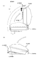
遊技領域の下方における遊技機用枠3の所定位置には、遊技者が把持して傾倒操作が可能なスティックコントローラ31Aが取り付けられている。スティックコントローラ31Aには、遊技者が押下操作可能なトリガボタンが設けられている。スティックコントローラ31Aに対する操作は、コントローラセンサユニット35A(図2参照)により検出される。
A
遊技領域の下方における遊技機用枠3の所定位置には、遊技者が押下操作などにより所定の指示操作を可能なプッシュボタン31Bが設けられている。プッシュボタン31Bに対する操作は、プッシュセンサ35B(図2参照)により検出される。
A
パチンコ遊技機1では、遊技者の動作(操作等)を検出する検出手段として、スティックコントローラ31Aやプッシュボタン31Bが設けられるが、これら以外の検出手段が設けられていてもよい。
The
(遊技の進行の概略)
パチンコ遊技機1が備える打球操作ハンドル30への遊技者による回転操作により、遊技球が遊技領域に向けて発射される。遊技球が通過ゲート41を通過すると、普通図柄表示器20による普図ゲームが開始される。なお、前回の普図ゲームの実行中の期間等に遊技球が通過ゲート41を通過した場合(遊技球が通過ゲート41を通過したが当該通過に基づく普図ゲームを直ちに実行できない場合)には、当該通過に基づく普図ゲームは所定の上限数(例えば4)まで保留される。
(Outline of the progress of the game)
The game ball is launched toward the game area by the rotation operation of the
この普図ゲームでは、特定の普通図柄(普図当り図柄)が停止表示されれば、普通図柄の表示結果が「普図当り」となる。その一方、確定普通図柄として、普図当り図柄以外の普通図柄(普図ハズレ図柄)が停止表示されれば、普通図柄の表示結果が「普図ハズレ」となる。「普図当り」となると、可変入賞球装置6Bを所定期間開放状態とする開放制御が行われる(第2始動入賞口が開放状態になる)。
In this normal symbol game, if a specific normal symbol (design per normal symbol) is stopped and displayed, the display result of the normal symbol becomes "per normal symbol". On the other hand, if a normal symbol other than a normal symbol (a normal symbol lost symbol) is stopped and displayed as a confirmed normal symbol, the display result of the normal symbol becomes "normal symbol lost". When it becomes "per-normal", the opening control is performed so that the variable winning
入賞球装置6Aに形成された第1始動入賞口に遊技球が進入すると、第1特別図柄表示装置4Aによる第1特図ゲームが開始される。
When the game ball enters the first starting winning opening formed in the winning
可変入賞球装置6Bに形成された第2始動入賞口に遊技球が進入すると、第2特別図柄表示装置4Bによる第2特図ゲームが開始される。
When the game ball enters the second starting winning opening formed in the variable winning
なお、特図ゲームの実行中の期間や、後述する大当り遊技状態や小当り遊技状態に制御されている期間に、遊技球が始動入賞口へ進入(入賞)した場合(始動入賞が発生したが当該始動入賞に基づく特図ゲームを直ちに実行できない場合)には、当該進入に基づく特図ゲームは所定の上限数(例えば4)までその実行が保留される。 In addition, when the game ball enters (wins) the start winning opening during the period during which the special figure game is being executed, or during the period controlled by the big hit game state or the small hit game state described later (starting prize has occurred). If the special figure game based on the start prize cannot be executed immediately), the execution of the special figure game based on the approach is suspended up to a predetermined upper limit number (for example, 4).
特図ゲームにおいて、確定特別図柄として特定の特別図柄(大当り図柄、例えば「7」、後述の大当り種別に応じて実際の図柄は異なる。)が停止表示されれば、「大当り」となり、大当り図柄とは異なる所定の特別図柄(小当り図柄、例えば「2」)が停止表示されれば、「小当り」となる。また、大当り図柄や小当り図柄とは異なる特別図柄(ハズレ図柄、例えば「-」)が停止表示されれば「ハズレ」となる。 In the special symbol game, if a specific special symbol (big hit symbol, for example, "7", the actual symbol differs depending on the jackpot type described later) is stopped and displayed as a confirmed special symbol, it becomes "big hit" and the jackpot symbol. If a predetermined special symbol (small hit symbol, for example, "2") different from the above is stopped and displayed, it becomes "small hit". Further, if a special symbol (missing symbol, for example, "-") different from the big hit symbol or the small hit symbol is stopped and displayed, it becomes "missing".
特図ゲームでの表示結果が「大当り」になった後には、遊技者にとって有利な有利状態として大当り遊技状態に制御される。特図ゲームでの表示結果が「小当り」になった後には、小当り遊技状態に制御される。 After the display result in the special figure game becomes "big hit", it is controlled to the big hit game state as an advantageous state advantageous for the player. After the display result in the special figure game becomes "small hit", it is controlled to the small hit game state.
大当り遊技状態では、特別可変入賞球装置7により形成される大入賞口が所定の態様で開放状態となる。当該開放状態は、所定期間(例えば29秒間や1.8秒間)の経過タイミングと、大入賞口に進入した遊技球の数が所定個数(例えば9個)に達するまでのタイミングと、のうちのいずれか早いタイミングまで継続される。前記所定期間は、1ラウンドにおいて大入賞口を開放することができる上限期間であり、以下、開放上限期間ともいう。このように大入賞口が開放状態となる1のサイクルをラウンド(ラウンド遊技)という。大当り遊技状態では、当該ラウンドが所定の上限回数(15回や2回)に達するまで繰り返し実行可能となっている。
In the big hit game state, the big winning opening formed by the special variable winning
大当り遊技状態においては、遊技者は、遊技球を大入賞口に進入させることで、賞球を得ることができる。従って、大当り遊技状態は、遊技者にとって有利な状態である。大当り遊技状態におけるラウンド数が多い程、また、開放上限期間が長い程遊技者にとって有利となる。 In the big hit game state, the player can obtain the prize ball by letting the game ball enter the big prize opening. Therefore, the jackpot gaming state is an advantageous state for the player. The larger the number of rounds in the jackpot game state and the longer the open upper limit period, the more advantageous it is for the player.
なお、「大当り」には、大当り種別が設定されている。例えば、大入賞口の開放態様(ラウンド数や開放上限期間)や、大当り遊技状態後の遊技状態(後述の、通常状態、時短状態、確変状態など)を複数種類用意し、これらに応じて大当り種別が設定されている。大当り種別として、多くの賞球を得ることができる大当り種別や、賞球の少ない又はほとんど賞球を得ることができない大当り種別が設けられていてもよい。 A big hit type is set for "big hit". For example, multiple types of opening modes (number of rounds and opening upper limit period) of the big winning opening and game states after the big hit gaming state (normal state, time saving state, probability change state, etc., which will be described later) are prepared, and the big hit is made according to these. The type is set. As the big hit type, a big hit type in which a large number of prize balls can be obtained and a big hit type in which a small number of prize balls or almost no prize balls can be obtained may be provided.
小当り遊技状態では、特別可変入賞球装置7により形成される大入賞口が所定の開放態様で開放状態となる。例えば、小当り遊技状態では、一部の大当り種別のときの大当り遊技状態と同様の開放態様(大入賞口の開放回数が上記ラウンド数と同じであり、かつ、大入賞口の閉鎖タイミングも同じ等)で大入賞口が開放状態となる。なお、大当り種別と同様に、「小当り」にも小当り種別を設けてもよい。
In the small hit game state, the large winning opening formed by the special variable winning
大当り遊技状態が終了した後は、上記大当り種別に応じて、時短状態や確変状態に制御されることがある。 After the jackpot game state is completed, it may be controlled to a time saving state or a probability change state according to the jackpot type.
時短状態では、平均的な特図変動時間(特図を変動させる期間)を通常状態よりも短縮させる制御(時短制御)が実行される。時短状態では、平均的な普図変動時間(普図を変動させる期間)を通常状態よりも短縮させたり、普図ゲームで「普図当り」となる確率を通常状態よりも向上させる等により、第2始動入賞口に遊技球が進入しやすくなる制御(高開放制御、高ベース制御)も実行される。時短状態は、特別図柄(特に第2特別図柄)の変動効率が向上する状態であるので、遊技者にとって有利な状態である。 In the time saving state, control (time saving control) is executed in which the average special figure fluctuation time (period in which the special figure is changed) is shortened from the normal state. In the time-saving state, the average fluctuation time of the normal map (the period during which the normal map is changed) is shortened from the normal state, and the probability of becoming a "normal map hit" in the normal map game is improved from the normal state. Control (high opening control, high base control) that makes it easier for the game ball to enter the second start winning opening is also executed. The time saving state is a state in which the variation efficiency of the special symbol (particularly the second special symbol) is improved, which is advantageous for the player.
確変状態(確率変動状態)では、時短制御に加えて、表示結果が「大当り」となる確率が通常状態よりも高くなる確変制御が実行される。確変状態は、特別図柄の変動効率が向上することに加えて「大当り」となりやすい状態であるので、遊技者にとってさらに有利な状態である。 In the probabilistic state (probability fluctuation state), in addition to the time saving control, the probability change control in which the probability that the display result becomes a "big hit" is higher than in the normal state is executed. The probabilistic state is a state in which the fluctuation efficiency of the special symbol is improved and the “big hit” is likely to occur, which is a more advantageous state for the player.
時短状態や確変状態は、所定回数の特図ゲームが実行されたことと、次回の大当り遊技状態が開始されたこと等といった、いずれか1つの終了条件が先に成立するまで継続する。所定回数の特図ゲームが実行されたことが終了条件となるものを、回数切り(回数切り時短、回数切り確変等)ともいう。 The time saving state and the probabilistic change state continue until any one of the end conditions such as the execution of the special figure game a predetermined number of times and the start of the next big hit game state are satisfied first. A game whose end condition is that the special figure game has been executed a predetermined number of times is also referred to as a number-cutting (time-cutting time reduction, number-cutting probability change, etc.).
通常状態とは、遊技者にとって有利な大当り遊技状態等の有利状態、時短状態、確変状態等の特別状態以外の遊技状態のことであり、普図ゲームにおける表示結果が「普図当り」となる確率及び特図ゲームにおける表示結果が「大当り」となる確率などのパチンコ遊技機1が、パチンコ遊技機1の初期設定状態(例えばシステムリセットが行われた場合のように、電源投入後に所定の復帰処理を実行しなかったとき)と同一に制御される状態である。
The normal state is a gaming state other than a special state such as an advantageous state such as a big hit gaming state that is advantageous for the player, a time saving state, and a probability change state, and the display result in the normal figure game is "normal figure hit". The
確変制御が実行されている状態を高確状態、確変制御が実行されていない状態を低確状態ともいう。時短制御が実行されている状態を高ベース状態、時短制御が実行されていない状態を低ベース状態ともいう。これらを組み合わせて、時短状態は低確高ベース状態、確変状態は高確高ベース状態、通常状態は低確低ベース状態などともいわれる。高確状態かつ低ベース状態は高確低ベース状態ともいう。 The state in which the probability change control is executed is also called a high probability state, and the state in which the probability change control is not executed is also called a low probability state. The state in which the time reduction control is executed is also called a high base state, and the state in which the time reduction control is not executed is also called a low base state. By combining these, it is also called a low-accuracy high-base state in a time-saving state, a high-accuracy high-base state in a probabilistic state, and a low-accuracy low-base state in a normal state. The high-accuracy state and low-base state are also called the high-accuracy low-base state.
小当り遊技状態が終了した後は、遊技状態の変更が行われず、特図ゲームの表示結果が「小当り」となる以前の遊技状態に継続して制御される(但し、「小当り」発生時の特図ゲームが、上記回数切りにおける上記所定回数目の特図ゲームである場合には、当然遊技状態が変更される)。なお、特図ゲームの表示結果として「小当り」がなくてもよい。 After the small hit game state ends, the game state is not changed, and the game state is continuously controlled to the game state before the display result of the special figure game becomes "small hit" (however, "small hit" occurs. If the special figure game at the time is the special figure game of the predetermined number of times in the above number of times cut, the game state is naturally changed). In addition, it is not necessary that there is no "small hit" as the display result of the special figure game.
なお、遊技状態は、大当り遊技状態中に遊技球が特定領域(例えば、大入賞口内の特定領域)を通過したことに基づいて、変化してもよい。例えば、遊技球が特定領域を通過したとき、その大当り遊技状態後に確変状態に制御してもよい。 The gaming state may change based on the fact that the gaming ball has passed through a specific area (for example, a specific area in the big winning opening) during the big hit game state. For example, when the game ball passes through a specific area, it may be controlled to a probable change state after the big hit game state.
(演出の進行など)
パチンコ遊技機1では、遊技の進行に応じて種々の演出(遊技の進行状況を報知したり、遊技を盛り上げたりする演出)が実行される。当該演出について以下説明する。なお、当該演出は、画像表示装置5に各種の演出画像を表示することによって行われるが、当該表示に加えて又は代えて、スピーカ8L、8Rからの音声出力、及び/又は、遊技効果ランプ9の点等/消灯、可動体32の動作等により行われてもよい。
(Progress of production, etc.)
In the
遊技の進行に応じて実行される演出として、画像表示装置5に設けられた「左」、「中」、「右」の飾り図柄表示エリア5L、5C、5Rでは、第1特図ゲーム又は第2特図ゲームが開始されることに対応して、飾り図柄の可変表示が開始される。第1特図ゲームや第2特図ゲームにおいて表示結果(確定特別図柄ともいう。)が停止表示されるタイミングでは、飾り図柄の可変表示の表示結果となる確定飾り図柄(3つの飾り図柄の組合せ)も停止表示(導出)される。
As an effect executed according to the progress of the game, in the decorative
飾り図柄の可変表示が開始されてから終了するまでの期間では、飾り図柄の可変表示の態様が所定のリーチ態様となる(リーチが成立する)ことがある。ここで、リーチ態様とは、画像表示装置5の画面上にて停止表示された飾り図柄が後述の大当り組合せの一部を構成しているときに未だ停止表示されていない飾り図柄については可変表示が継続している態様などのことである。
In the period from the start to the end of the variable display of the decorative symbol, the variable display mode of the decorative symbol may become a predetermined reach mode (reach is established). Here, the reach mode is a variable display for a decorative symbol that has not yet been stopped and displayed when the decorative symbol that has been stopped and displayed on the screen of the
また、飾り図柄の可変表示中に上記リーチ態様となったことに対応してリーチ演出が実行される。パチンコ遊技機1では、演出態様に応じて表示結果(特図ゲームの表示結果や飾り図柄の可変表示の表示結果)が「大当り」となる割合(大当り信頼度、大当り期待度とも呼ばれる。)が異なる複数種類のリーチ演出が実行される。リーチ演出には、例えば、ノーマルリーチと、ノーマルリーチよりも大当り信頼度の高いスーパーリーチと、がある。
In addition, the reach effect is executed in response to the above-mentioned reach mode during the variable display of the decorative pattern. In the
特図ゲームの表示結果が「大当り」となるときには、画像表示装置5の画面上において、飾り図柄の可変表示の表示結果として、予め定められた大当り組合せとなる確定飾り図柄が導出される(飾り図柄の可変表示の表示結果が「大当り」となる)。一例として、「左」、「中」、「右」の飾り図柄表示エリア5L、5C、5Rにおける所定の有効ライン上に同一の飾り図柄(例えば、「7」等)が揃って停止表示される。
When the display result of the special figure game is "big hit", a definite decorative symbol that is a predetermined jackpot combination is derived as a display result of the variable display of the decorative symbol on the screen of the image display device 5 (decoration). The display result of the variable display of the symbol is "big hit"). As an example, the same decorative symbols (for example, "7") are aligned and stopped and displayed on predetermined effective lines in the decorative
大当り遊技状態の終了後に確変状態に制御される「確変大当り」である場合には、奇数の飾り図柄(例えば、「7」等)が揃って停止表示され、大当り遊技状態の終了後に確変状態に制御されない「非確変大当り(通常大当り)」である場合には、偶数の飾り図柄(例えば、「6」等)が揃って停止表示されるようにしてもよい。この場合、奇数の飾り図柄を確変図柄、偶数の飾り図柄を非確変図柄(通常図柄)ともいう。非確変図柄でリーチ態様となった後に、最終的に「確変大当り」となる昇格演出を実行するようにしてもよい。 In the case of "probability change jackpot" which is controlled to the probability change state after the end of the jackpot game state, an odd number of decorative symbols (for example, "7" etc.) are all stopped and displayed, and the probability change state is changed after the end of the jackpot game state. In the case of an uncontrolled "non-probability variable jackpot (normal jackpot)", an even number of decorative symbols (for example, "6") may be stopped and displayed. In this case, the odd-numbered decorative symbol is also referred to as a probabilistic symbol, and the even-numbered decorative symbol is also referred to as a non-probable variable symbol (normal symbol). After the non-probability pattern becomes the reach mode, the promotion effect that finally becomes the "probability change jackpot" may be executed.
特図ゲームの表示結果が「小当り」となるときには、画像表示装置5の画面上において、飾り図柄の可変表示の表示結果として、予め定められた小当り組合せとなる確定飾り図柄(例えば、「1 3 5」等)が導出される(飾り図柄の可変表示の表示結果が「小当り」となる)。一例として、「左」、「中」、「右」の飾り図柄表示エリア5L、5C、5Rにおける所定の有効ライン上にチャンス目を構成する飾り図柄が停止表示される。なお、特図ゲームの表示結果が、一部の大当り種別(小当り遊技状態と同様の態様の大当り遊技状態の大当り種別)の「大当り」となるときと、「小当り」となるときとで、共通の確定飾り図柄が導出表示されてもよい。
When the display result of the special figure game is "small hit", the fixed decorative symbol (for example, "for example,") which is a predetermined small hit combination as the display result of the variable display of the decorative symbol on the screen of the
特図ゲームの表示結果が「ハズレ」となる場合には、飾り図柄の可変表示の態様がリーチ態様とならずに、飾り図柄の可変表示の表示結果として、非リーチ組合せの確定飾り図柄(「非リーチハズレ」ともいう。)が停止表示される(飾り図柄の可変表示の表示結果が「非リーチハズレ」となる)ことがある。また、表示結果が「ハズレ」となる場合には、飾り図柄の可変表示の態様がリーチ態様となった後に、飾り図柄の可変表示の表示結果として、大当り組合せでない所定のリーチ組合せ(「リーチハズレ」ともいう)の確定飾り図柄が停止表示される(飾り図柄の可変表示の表示結果が「リーチハズレ」となる)こともある。 When the display result of the special figure game is "missing", the variable display mode of the decorative symbol is not the reach mode, and the display result of the variable display of the decorative symbol is a definite decorative symbol of a non-reach combination ("" (Also referred to as "non-reach loss") may be stopped and displayed (the display result of the variable display of the decorative pattern may be "non-reach loss"). In addition, when the display result is "missing", after the variable display mode of the decorative symbol becomes the reach mode, the display result of the variable display of the decorative symbol is a predetermined reach combination ("reach loss") that is not a big hit combination. The confirmed decorative symbol (also referred to as) may be stopped and displayed (the display result of the variable display of the decorative symbol may be "reach loss").
パチンコ遊技機1が実行可能な演出には、上記の可変表示対応表示(保留表示やアクティブ表示)を表示することも含まれる。また、他の演出として、例えば、大当り信頼度を予告する予告演出等が飾り図柄の可変表示中に実行される。予告演出には、実行中の可変表示における大当り信頼度を予告する予告演出や、実行前の可変表示(実行が保留されている可変表示)における大当り信頼度を予告する先読み予告演出がある。先読み予告演出として、可変表示対応表示(保留表示やアクティブ表示)の表示態様を通常とは異なる態様に変化させる演出が実行されるようにしてもよい。
The effect that the
また、画像表示装置5において、飾り図柄の可変表示中に飾り図柄を一旦仮停止させた後に可変表示を再開させることで、1回の可変表示を擬似的に複数回の可変表示のように見せる擬似連演出を実行するようにしてもよい。
Further, in the
大当り遊技状態中にも、大当り遊技状態を報知する大当り中演出が実行される。大当り中演出としては、ラウンド数を報知する演出や、大当り遊技状態の価値が向上することを示す昇格演出が実行されてもよい。また、小当り遊技状態中にも、小当り遊技状態を報知する小当り中演出が実行される。なお、小当り遊技状態中と、一部の大当り種別(小当り遊技状態と同様の態様の大当り遊技状態の大当り種別で、例えばその後の遊技状態を高確状態とする大当り種別)での大当り遊技状態とで、共通の演出を実行することで、現在が小当り遊技状態中であるか、大当り遊技状態中であるかを遊技者に分からないようにしてもよい。そのような場合であれば、小当り遊技状態の終了後と大当り遊技状態の終了後とで共通の演出を実行することで、高確状態であるか低確状態であるかを識別できないようにしてもよい。 Even during the big hit game state, the big hit middle effect that notifies the big hit game state is executed. As the big hit middle effect, an effect of notifying the number of rounds and a promotion effect indicating that the value of the big hit gaming state is improved may be executed. Further, even during the small hit game state, the small hit middle effect for notifying the small hit game state is executed. It should be noted that the big hit game during the small hit game state and in some big hit types (the big hit type of the big hit game state having the same aspect as the small hit game state, for example, the big hit type in which the subsequent game state is a highly accurate state). By executing a common effect depending on the state, the player may not know whether the player is currently in the small hit game state or the big hit game state. In such a case, by executing a common effect after the end of the small hit game state and after the end of the big hit game state, it is not possible to distinguish between the high probability state and the low probability state. You may.
また、例えば特図ゲーム等が実行されていないときには、画像表示装置5にデモ(デモンストレーション)画像が表示される(客待ちデモ演出が実行される)。 Further, for example, when a special figure game or the like is not executed, a demo (demonstration) image is displayed on the image display device 5 (a customer waiting demo effect is executed).
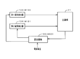
(基板構成)
パチンコ遊技機1には、例えば図2に示すような主基板11、演出制御基板12、音声制御基板13、ランプ制御基板14、中継基板15などが搭載されている。その他にも、パチンコ遊技機1の背面には、例えば払出制御基板、情報端子基板、発射制御基板、電源基板などといった、各種の基板が配置されている。
(Board configuration)
For example, the
主基板11は、メイン側の制御基板であり、パチンコ遊技機1における上記遊技の進行(特図ゲームの実行(保留の管理を含む)、普図ゲームの実行(保留の管理を含む)、大当り遊技状態、小当り遊技状態、遊技状態など)を制御する機能を有する。主基板11は、遊技制御用マイクロコンピュータ100、スイッチ回路110、ソレノイド回路111などを有する。
The
主基板11に搭載された遊技制御用マイクロコンピュータ100は、例えば1チップのマイクロコンピュータであり、ROM(Read Only Memory)101と、RAM(Random Access Memory)102と、CPU(Central Processing Unit)103と、乱数回路104と、I/O(Input/Output port)105とを備える。
The
CPU103は、ROM101に記憶されたプログラムを実行することにより、遊技の進行を制御する処理(主基板11の機能を実現する処理)を行う。このとき、ROM101が記憶する各種データ(後述の変動パターン、後述の演出制御コマンド、後述の各種決定を行う際に参照される各種テーブルなどのデータ)が用いられ、RAM102がメインメモリとして使用される。RAM102は、その一部または全部がパチンコ遊技機1に対する電力供給が停止しても、所定期間記憶内容が保存されるバックアップRAMとなっている。なお、ROM101に記憶されたプログラムの全部又は一部をRAM102に展開して、RAM102上で実行するようにしてもよい。
The
乱数回路104は、遊技の進行を制御するときに使用される各種の乱数値(遊技用乱数)を示す数値データを更新可能にカウントする。遊技用乱数は、CPU103が所定のコンピュータプログラムを実行することで更新されるもの(ソフトウェアで更新されるもの)であってもよい。
The
I/O105は、例えば各種信号(後述の検出信号)が入力される入力ポートと、各種信号(第1特別図柄表示装置4A、第2特別図柄表示装置4B、普通図柄表示器20、第1保留表示器25A、第2保留表示器25B、普図保留表示器25Cなどを制御(駆動)する信号、ソレノイド駆動信号)を伝送するための出力ポートとを含んで構成される。
The I /
スイッチ回路110は、遊技球検出用の各種スイッチ(ゲートスイッチ21、始動口スイッチ(第1始動口スイッチ22Aおよび第2始動口スイッチ22B)、カウントスイッチ23)からの検出信号(遊技球が通過又は進入してスイッチがオンになったことを示す検出信号など)を取り込んで遊技制御用マイクロコンピュータ100に伝送する。検出信号の伝送により、遊技球の通過又は進入が検出されたことになる。
The
ソレノイド回路111は、遊技制御用マイクロコンピュータ100からのソレノイド駆動信号(例えば、ソレノイド81やソレノイド82をオンする信号など)を、普通電動役物用のソレノイド81や大入賞口扉用のソレノイド82に伝送する。
The
主基板11(遊技制御用マイクロコンピュータ100)は、遊技の進行の制御の一部として、遊技の進行に応じて演出制御コマンド(遊技の進行状況等を指定(通知)するコマンド)を演出制御基板12に供給する。主基板11から出力された演出制御コマンドは、中継基板15により中継され、演出制御基板12に供給される。当該演出制御コマンドには、例えば主基板11における各種の決定結果(例えば、特図ゲームの表示結果(大当り種別を含む。)、特図ゲームを実行する際に使用される変動パターン(詳しくは後述))、遊技の状況(例えば、可変表示の開始や終了、大入賞口の開放状況、入賞の発生、保留記憶数、遊技状態)、エラーの発生等を指定するコマンド等が含まれる。
The main board 11 (
演出制御基板12は、主基板11とは独立したサブ側の制御基板であり、演出制御コマンドを受信し、受信した演出制御コマンドに基づいて演出(遊技の進行に応じた種々の演出であり、可動体32の駆動、エラー報知、電断復旧の報知等の各種報知を含む)を実行する機能を有する。
The
演出制御基板12には、演出制御用CPU120と、ROM121と、RAM122と、表示制御部123と、乱数回路124と、I/O125とが搭載されている。
The
演出制御用CPU120は、ROM121に記憶されたプログラムを実行することにより、表示制御部123とともに演出を実行するための処理(演出制御基板12の上記機能を実現するための処理であり、実行する演出の決定等を含む)を行う。このとき、ROM121が記憶する各種データ(各種テーブルなどのデータ)が用いられ、RAM122がメインメモリとして使用される。
The
演出制御用CPU120は、コントローラセンサユニット35Aやプッシュセンサ35Bからの検出信号(遊技者による操作を検出したときに出力される信号であり、操作内容を適宜示す信号)に基づいて演出の実行を表示制御部123に指示することもある。
The
表示制御部123は、VDP(Video Display Processor)、CGROM(Character Generator ROM)、VRAM(Video RAM)などを備え、演出制御用CPU120からの演出の実行指示に基づき、演出を実行する。
The
表示制御部123は、演出制御用CPU120からの演出の実行指示に基づき、実行する演出に応じた映像信号を画像表示装置5に供給することで、演出画像を画像表示装置5に表示させる。表示制御部123は、さらに、演出画像の表示に同期した音声出力や、遊技効果ランプ9の点灯/消灯を行うため、音指定信号(出力する音声を指定する信号)を音声制御基板13に供給したり、ランプ信号(ランプの点灯/消灯態様を指定する信号)をランプ制御基板14に供給したりする。また、表示制御部123は、可動体32を動作させる信号を当該可動体32又は当該可動体32を駆動する駆動回路に供給する。
The
音声制御基板13は、スピーカ8L、8Rを駆動する各種回路を搭載しており、当該音指定信号に基づきスピーカ8L、8Rを駆動し、当該音指定信号が指定する音声をスピーカ8L、8Rから出力させる。
The
ランプ制御基板14は、遊技効果ランプ9を駆動する各種回路を搭載しており、当該ランプ信号に基づき遊技効果ランプ9を駆動し、当該ランプ信号が指定する態様で遊技効果ランプ9を点灯/消灯する。このようにして、表示制御部123は、音声出力、ランプの点灯/消灯を制御する。
The
なお、音声出力、ランプの点灯/消灯の制御(音指定信号やランプ信号の供給等)、可動体32の制御(可動体32を動作させる信号の供給等)は、演出制御用CPU120が実行するようにしてもよい。
The
乱数回路124は、各種演出を実行するために使用される各種の乱数値(演出用乱数)を示す数値データを更新可能にカウントする。演出用乱数は、演出制御用CPU120が所定のコンピュータプログラムを実行することで更新されるもの(ソフトウェアで更新されるもの)であってもよい。
The
演出制御基板12に搭載されたI/O125は、例えば主基板11などから伝送された演出制御コマンドを取り込むための入力ポートと、各種信号(映像信号、音指定信号、ランプ信号)を伝送するための出力ポートとを含んで構成される。
The I /
演出制御基板12、音声制御基板13、ランプ制御基板14といった、主基板11以外の基板をサブ基板ともいう。パチンコ遊技機1のようにサブ基板が機能別に複数設けられていてもよいし、1のサブ基板が複数の機能を有するように構成してもよい。
Boards other than the
(動作)
次に、パチンコ遊技機1の動作(作用)を説明する。
(motion)
Next, the operation (action) of the
(主基板11の主要な動作)
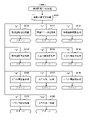
まず、主基板11における主要な動作を説明する。パチンコ遊技機1に対して電力供給が開始されると、遊技制御用マイクロコンピュータ100が起動し、CPU103によって遊技制御メイン処理が実行される。図3は、主基板11におけるCPU103が実行する遊技制御メイン処理を示すフローチャートである。
(Main operation of main board 11)
First, the main operation of the
図3に示す遊技制御メイン処理では、CPU103は、まず、割込禁止に設定する(ステップS1)。続いて、必要な初期設定を行う(ステップS2)。初期設定には、スタックポインタの設定、内蔵デバイス(CTC(カウンタ/タイマ回路)、パラレル入出力ポート等)のレジスタ設定、RAM102をアクセス可能状態にする設定等が含まれる。
In the game control main process shown in FIG. 3, the
次いで、クリアスイッチからの出力信号がオンであるか否かを判定する(ステップS3)。クリアスイッチは、例えば電源基板に搭載されている。クリアスイッチがオンの状態で電源が投入されると、出力信号(クリア信号)が入力ポートを介して遊技制御用マイクロコンピュータ100に入力される。クリアスイッチからの出力信号がオンである場合(ステップS3;Yes)、初期化処理(ステップS8)を実行する。初期化処理では、CPU103は、RAM102に記憶されるフラグ、カウンタ、バッファをクリアするRAMクリア処理を行い、作業領域に初期値を設定する。
Next, it is determined whether or not the output signal from the clear switch is ON (step S3). The clear switch is mounted on, for example, a power supply board. When the power is turned on with the clear switch turned on, an output signal (clear signal) is input to the
また、CPU103は、初期化を指示する演出制御コマンドを演出制御基板12に送信する(ステップS9)。演出制御用CPU120は、当該演出制御コマンドを受信すると、例えば画像表示装置5において、遊技機の制御の初期化がなされたことを報知するための画面表示を行う。
Further, the
クリアスイッチからの出力信号がオンでない場合には(ステップS3;No)、RAM102(バックアップRAM)にバックアップデータが保存されているか否かを判定する(ステップS4)。不測の停電等(電断)によりパチンコ遊技機1への電力供給が停止したときには、CPU103は、当該電力供給の停止によって動作できなくなる直前に、電源供給停止時処理を実行する。この電源供給停止時処理では、RAM102にデータをバックアップすることを示すバックアップフラグをオンする処理、RAM102のデータ保護処理等が実行される。データ保護処理には、誤り検出符号(チェックサム、パリティビット等)の付加、各種データをバックアップする処理が含まれる。バックアップされるデータには、遊技を進行するための各種データ(各種フラグ、各種タイマの状態等を含む)の他、前記バックアップフラグの状態や誤り検出符号も含まれる。ステップS4では、バックアップフラグがオンであるか否かを判定する。バックアップフラグがオフでRAM102にバックアップデータが記憶されていない場合(ステップS4;No)、初期化処理(ステップS8)を実行する。
If the output signal from the clear switch is not on (step S3; No), it is determined whether or not the backup data is stored in the RAM 102 (backup RAM) (step S4). When the power supply to the
RAM102にバックアップデータが記憶されている場合(ステップS4;Yes)、CPU103は、バックアップしたデータのデータチェックを行い(誤り検出符号を用いて行われる)、データが正常か否かを判定する(ステップS5)。ステップS5では、例えば、パリティビットやチェックサムにより、RAM102のデータが、電力供給停止時のデータと一致するか否かを判定する。これらが一致すると判定された場合、RAM102のデータが正常であると判定する。
When the backup data is stored in the RAM 102 (step S4; Yes), the
RAM102のデータが正常でないと判定された場合(ステップS5;No)、内部状態を電力供給停止時の状態に戻すことができないので、初期化処理(ステップS8)を実行する。
When it is determined that the data in the
RAM102のデータが正常であると判定された場合(ステップS5;Yes)、CPU103は、主基板11の内部状態を電力供給停止時の状態に戻すための復旧処理(ステップS6)を行う。復旧処理では、CPU103は、RAM102の記憶内容(バックアップしたデータの内容)に基づいて作業領域の設定を行う。これにより、電力供給停止時の遊技状態に復旧し、特別図柄の変動中であった場合には、後述の遊技制御用タイマ割込み処理の実行によって、復旧前の状態から特別図柄の変動が再開されることになる。
When it is determined that the data in the
そして、CPU103は、電断からの復旧を指示する演出制御コマンドを演出制御基板12に送信する(ステップS7)。これに合わせて、バックアップされている電断前の遊技状態を指定する演出制御コマンドや、特図ゲームの実行中であった場合には当該実行中の特図ゲームの表示結果を指定する演出制御コマンドを送信するようにしてもよい。これらコマンドは、後述の特別図柄プロセス処理で送信設定されるコマンドと同じコマンドを使用できる。演出制御用CPU120は、電断からの復旧時を特定する演出制御コマンドを受信すると、例えば画像表示装置5において、電断からの復旧がなされたこと又は電断からの復旧中であることを報知するための画面表示を行う。演出制御用CPU120は、前記演出制御コマンドに基づいて、適宜の画面表示を行うようにしてもよい。
Then, the
復旧処理または初期化処理を終了して演出制御基板12に演出制御コマンドを送信した後には、CPU103は、乱数回路104を初期設定する乱数回路設定処理を実行する(ステップS10)。そして、所定時間(例えば2ms)毎に定期的にタイマ割込がかかるように遊技制御用マイクロコンピュータ100に内蔵されているCTCのレジスタの設定を行い(ステップS11)、割込みを許可する(ステップS12)。その後、ループ処理に入る。以後、所定時間(例えば2ms)ごとにCTCから割込み要求信号がCPU103へ送出され、CPU103は定期的にタイマ割込み処理を実行することができる。
After the restoration process or the initialization process is completed and the effect control command is transmitted to the
こうした遊技制御メイン処理を実行したCPU103は、CTCからの割込み要求信号を受信して割込み要求を受け付けると、図4のフローチャートに示す遊技制御用タイマ割込み処理を実行する。図4に示す遊技制御用タイマ割込み処理を開始すると、CPU103は、まず、所定のスイッチ処理を実行することにより、スイッチ回路110を介してゲートスイッチ21、第1始動口スイッチ22A、第2始動口スイッチ22B、カウントスイッチ23といった各種スイッチからの検出信号の受信の有無を判定する(ステップS21)。続いて、所定のメイン側エラー処理を実行することにより、パチンコ遊技機1の異常診断を行い、その診断結果に応じて必要ならば警告を発生可能とする(ステップS22)。この後、所定の情報出力処理を実行することにより、例えばパチンコ遊技機1の外部に設置されたホール管理用コンピュータに供給される大当り情報(大当りの発生回数等を示す情報)、始動情報(始動入賞の回数等を示す情報)、確率変動情報(確変状態となった回数等を示す情報)などのデータを出力する(ステップS23)。
When the
情報出力処理に続いて、主基板11の側で用いられる遊技用乱数の少なくとも一部をソフトウェアにより更新するための遊技用乱数更新処理を実行する(ステップS24)。この後、CPU103は、特別図柄プロセス処理を実行する(ステップS25)。CPU103がタイマ割込み毎に特別図柄プロセス処理を実行することにより、特図ゲームの実行及び保留の管理や、大当り遊技状態や小当り遊技状態の制御、遊技状態の制御などが実現される(詳しくは後述)。
Following the information output process, a game random number update process for updating at least a part of the game random numbers used on the
特別図柄プロセス処理に続いて、普通図柄プロセス処理が実行される(ステップS26)。CPU103がタイマ割込み毎に普通図柄プロセス処理を実行することにより、ゲートスイッチ21からの検出信号に基づく(通過ゲート41に遊技球が通過したことに基づく)普図ゲームの実行及び保留の管理や、「普図当り」に基づく可変入賞球装置6Bの開放制御などを可能にする。普図ゲームの実行は、普通図柄表示器20を駆動することにより行われ、普図保留表示器25Cを点灯させることにより普図保留数を表示する。
Following the special symbol process process, the normal symbol process process is executed (step S26). By executing the normal symbol process processing for each timer interrupt, the
普通図柄プロセス処理を実行した後、遊技制御用タイマ割込み処理の一部として、電断が発生したときの処理、賞球を払い出すための処理等などが行われてもよい。その後、CPU103は、コマンド制御処理を実行する(ステップS27)。CPU103は、上記各処理にて演出制御コマンドを送信設定することがある。ステップS27のコマンド制御処理では、送信設定された演出制御コマンドを演出制御基板12などのサブ側の制御基板に対して伝送させる処理が行われる。コマンド制御処理を実行した後には、割込みを許可してから、遊技制御用タイマ割込み処理を終了する。
After executing the normal symbol process process, as a part of the game control timer interrupt process, a process when a power failure occurs, a process for paying out a prize ball, and the like may be performed. After that, the
図5は、特別図柄プロセス処理として、図4に示すステップS25にて実行される処理の一例を示すフローチャートである。この特別図柄プロセス処理において、CPU103は、まず、始動入賞判定処理を実行する(ステップS101)。
FIG. 5 is a flowchart showing an example of the process executed in step S25 shown in FIG. 4 as the special symbol process process. In this special symbol process process, the
始動入賞判定処理では、始動入賞の発生を検出し、RAM102の所定領域に保留情報を格納し保留記憶数を更新する処理が実行される。始動入賞が発生すると、表示結果(大当り種別を含む)や変動パターンを決定するための乱数値が抽出され、保留情報として記憶される。また、抽出した乱数値に基づいて、表示結果や変動パターンを先読み判定する処理が実行されてもよい。保留情報や保留記憶数を記憶した後には、演出制御基板12に始動入賞の発生、保留記憶数、先読み判定等の判定結果を指定するための演出制御コマンドを送信するための送信設定が行われる。こうして送信設定された始動入賞時の演出制御コマンドは、例えば特別図柄プロセス処理が終了した後、図4に示すステップS27のコマンド制御処理が実行されることなどにより、主基板11から演出制御基板12に対して伝送される。
In the start winning determination process, a process of detecting the occurrence of a start winning, storing the hold information in a predetermined area of the
S101にて始動入賞判定処理を実行した後、CPU103は、RAM102に設けられた特図プロセスフラグの値に応じて、ステップS110~S120の処理のいずれかを選択して実行する。なお、特別図柄プロセス処理の各処理(ステップS110~S120)では、各処理に対応した演出制御コマンドを演出制御基板12に送信するための送信設定が行われる。
After executing the start winning determination process in S101, the
ステップS110の特別図柄通常処理は、特図プロセスフラグの値が“0”(初期値)のときに実行される。この特別図柄通常処理では、保留情報の有無などに基づいて、第1特図ゲーム又は第2特図ゲームを開始するか否かの判定が行われる。また、特別図柄通常処理では、表示結果決定用の乱数値に基づき、特別図柄や飾り図柄の表示結果を「大当り」または「小当り」とするか否かや「大当り」とする場合の大当り種別を、その表示結果が導出表示される以前に決定(事前決定)する。さらに、特別図柄通常処理では、決定された表示結果に対応して、特図ゲームにおいて停止表示させる確定特別図柄(大当り図柄や小当り図柄、ハズレ図柄のいずれか)が設定される。その後、特図プロセスフラグの値が“1”に更新され、特別図柄通常処理は終了する。なお、第2特図を用いた特図ゲームが第1特図を用いた特図ゲームよりも優先して実行されるようにしてもよい(特図2優先消化ともいう)。また、第1始動入賞口及び第2始動入賞口への遊技球の入賞順序を記憶し、入賞順に特図ゲームの開始条件を成立させるようにしてもよい(入賞順消化ともいう)。 The special symbol normal processing in step S110 is executed when the value of the special symbol process flag is “0” (initial value). In this special symbol normal processing, it is determined whether or not to start the first special figure game or the second special figure game based on the presence or absence of the reserved information. In addition, in the special symbol normal processing, whether or not the display result of the special symbol or decorative symbol is set to "big hit" or "small hit" based on the random number value for determining the display result, and the big hit type when the display result is set to "big hit". Is determined (predetermined) before the display result is derived and displayed. Further, in the special symbol normal processing, a definite special symbol (either a big hit symbol, a small hit symbol, or a lost symbol) to be stopped and displayed in the special symbol game is set according to the determined display result. After that, the value of the special symbol process flag is updated to "1", and the special symbol normal processing ends. It should be noted that the special figure game using the second special figure may be executed with priority over the special figure game using the first special figure (also referred to as special figure 2 priority digestion). Further, the winning order of the game balls to the first starting winning opening and the second starting winning opening may be stored, and the starting condition of the special figure game may be satisfied in the winning order (also referred to as winning order digestion).
乱数値に基づき各種の決定を行う場合には、ROM101に格納されている各種のテーブル(乱数値と比較される決定値が決定結果に割り当てられているテーブル)が参照される。主基板11における他の決定、演出制御基板12における各種の決定についても同じである。演出制御基板12においては、各種のテーブルがROM121に格納されている。
When making various decisions based on the random number value, various tables stored in the ROM 101 (a table in which the decision value to be compared with the random number value is assigned to the decision result) are referred to. The same applies to other decisions on the
ステップS111の変動パターン設定処理は、特図プロセスフラグの値が“1”のときに実行される。この変動パターン設定処理には、表示結果を「大当り」または「小当り」とするか否かの事前決定結果等に基づき、変動パターン決定用の乱数値を用いて変動パターンを複数種類のいずれかに決定する処理などが含まれている。変動パターン設定処理では、変動パターンを決定したときに、特図プロセスフラグの値が“2”に更新され、変動パターン設定処理は終了する。 The variation pattern setting process in step S111 is executed when the value of the special figure process flag is “1”. In this fluctuation pattern setting process, one of a plurality of types of fluctuation patterns is used by using a random value for determining the fluctuation pattern based on the pre-determination result of whether or not the display result is "big hit" or "small hit". It includes the process of determining. In the variation pattern setting process, when the variation pattern is determined, the value of the special figure process flag is updated to "2", and the variation pattern setting process ends.
変動パターンは、特図ゲームの実行時間(特図変動時間)(飾り図柄の可変表示の実行時間でもある)や、飾り図柄の可変表示の態様(リーチの有無等)、飾り図柄の可変表示中の演出内容(リーチ演出の種類等)を指定するものであり、可変表示パターンとも呼ばれる。 The fluctuation pattern includes the execution time of the special figure game (special figure fluctuation time) (which is also the execution time of the variable display of the decorative symbol), the variable display mode of the decorative symbol (presence or absence of reach, etc.), and the variable display of the decorative symbol. It specifies the content of the effect (type of reach effect, etc.), and is also called a variable display pattern.
ステップS112の特別図柄変動処理は、特図プロセスフラグの値が“2”のときに実行される。この特別図柄変動処理には、第1特別図柄表示装置4Aや第2特別図柄表示装置4Bにおいて特別図柄を変動させるための設定を行う処理や、その特別図柄が変動を開始してからの経過時間を計測する処理などが含まれている。また、計測された経過時間が変動パターンに対応する特図変動時間に達したか否かの判定も行われる。そして、特別図柄の変動を開始してからの経過時間が特図変動時間に達したときには、特図プロセスフラグの値が“3”に更新され、特別図柄変動処理は終了する。
The special symbol variation process in step S112 is executed when the value of the special symbol process flag is “2”. In this special symbol variation processing, the processing for setting the special symbol to be varied in the first special
ステップS113の特別図柄停止処理は、特図プロセスフラグの値が“3”のときに実行される。この特別図柄停止処理には、第1特別図柄表示装置4Aや第2特別図柄表示装置4Bにて特別図柄の変動を停止させ、特別図柄の表示結果となる確定特別図柄を停止表示(導出)させるための設定を行う処理が含まれている。そして、表示結果が「大当り」である場合には特図プロセスフラグの値が“4”に更新される。その一方で、大当りフラグがオフであり、表示結果が「小当り」である場合には、特図プロセスフラグの値が“8”に更新される。また、表示結果が「ハズレ」である場合には、特図プロセスフラグの値が“0”に更新される。表示結果が「小当り」又は「ハズレ」である場合、時短状態や確変状態に制御されているときであって、回数切りの終了成立する場合には、遊技状態も更新される。特図プロセスフラグの値が更新されると、特別図柄停止処理は終了する。
The special symbol stop process in step S113 is executed when the value of the special symbol process flag is “3”. In this special symbol stop process, the first special
ステップS114の大当り開放前処理は、特図プロセスフラグの値が“4”のときに実行される。この大当り開放前処理には、表示結果が「大当り」となったことなどに基づき、大当り遊技状態においてラウンドの実行を開始して大入賞口を開放状態とするための設定を行う処理などが含まれている。大入賞口を開放状態とするときには、大入賞口扉用のソレノイド82に対してソレノイド駆動信号を供給する処理が実行される。このときには、例えば大当り種別がいずれであるかに対応して、大入賞口を開放状態とする開放上限期間や、ラウンドの上限実行回数を設定する。これらの設定が終了すると、特図プロセスフラグの値が“5”に更新され、大当り開放前処理は終了する。
The jackpot opening preprocessing in step S114 is executed when the value of the special figure process flag is “4”. This big hit pre-opening process includes a process of setting to open the big winning opening by starting the execution of the round in the big hit game state based on the display result being "big hit". It has been. When the large winning opening is opened, a process of supplying a solenoid drive signal to the
ステップS115の大当り開放中処理は、特図プロセスフラグの値が“5”のときに実行される。この大当り開放中処理には、大入賞口を開放状態としてからの経過時間を計測する処理や、その計測した経過時間やカウントスイッチ23によって検出された遊技球の個数などに基づいて、大入賞口を開放状態から閉鎖状態に戻すタイミングとなったか否かを判定する処理などが含まれている。そして、大入賞口を閉鎖状態に戻すときには、大入賞口扉用のソレノイド82に対するソレノイド駆動信号の供給を停止させる処理などを実行した後、特図プロセスフラグの値が“6”に更新し、大当り開放中処理を終了する。
The process of opening the jackpot in step S115 is executed when the value of the special figure process flag is “5”. In this big hit opening process, the big winning opening is based on the process of measuring the elapsed time since the big winning opening is opened, the measured elapsed time, the number of game balls detected by the
ステップS116の大当り開放後処理は、特図プロセスフラグの値が“6”のときに実行される。この大当り開放後処理には、大入賞口を開放状態とするラウンドの実行回数が設定された上限実行回数に達したか否かを判定する処理や、上限実行回数に達した場合に大当り遊技状態を終了させるための設定を行う処理などが含まれている。そして、ラウンドの実行回数が上限実行回数に達していないときには、特図プロセスフラグの値が“5”に更新される一方、ラウンドの実行回数が上限実行回数に達したときには、特図プロセスフラグの値が“7”に更新される。特図プロセスフラグの値が更新されると、大当り解放後処理は終了する。 The post-processing after opening the jackpot in step S116 is executed when the value of the special figure process flag is “6”. In this big hit post-opening process, there is a process of determining whether or not the number of rounds to be executed with the big winning opening open has reached the set maximum number of executions, and a big hit game state when the maximum number of executions has been reached. It includes the process of making settings to terminate. Then, when the number of round executions has not reached the upper limit, the value of the special figure process flag is updated to "5", while when the number of round executions reaches the upper limit, the special figure process flag is set. The value is updated to "7". When the value of the special figure process flag is updated, the jackpot release post-processing ends.
ステップS117の大当り終了処理は、特図プロセスフラグの値が“7”のときに実行される。この大当り終了処理には、大当り遊技状態の終了を報知する演出動作としてのエンディング演出が実行される期間に対応した待ち時間が経過するまで待機する処理や、大当り遊技状態の終了に対応して確変制御や時短制御を開始するための各種の設定を行う処理などが含まれている。こうした設定が行われたときには、特図プロセスフラグの値が“0”に更新され、大当り終了処理は終了する。 The jackpot end process of step S117 is executed when the value of the special figure process flag is “7”. In this big hit end process, there is a process of waiting until the waiting time corresponding to the period corresponding to the period in which the ending effect as an effect operation for notifying the end of the big hit game state is executed, and a probable change corresponding to the end of the big hit game state. It includes processing to make various settings for starting control and time reduction control. When such a setting is made, the value of the special figure process flag is updated to "0", and the jackpot end process ends.
ステップS118の小当り開放前処理は、特図プロセスフラグの値が“8”のときに実行される。この小当り開放前処理には、表示結果が「小当り」となったことに基づき、小当り遊技状態において大入賞口を開放状態とするための設定を行う処理などが含まれている。このときには、特図プロセスフラグの値が“9”に更新され、小当り開放前処理は終了する。 The small hit release preprocessing in step S118 is executed when the value of the special figure process flag is “8”. This small hit pre-opening process includes a process of setting the large winning opening to be in the open state in the small hit game state based on the display result being "small hit". At this time, the value of the special figure process flag is updated to "9", and the small hit opening preprocessing ends.
ステップS119の小当り開放中処理は、特図プロセスフラグの値が“9”のときに実行される。この小当り開放中処理には、大入賞口を開放状態としてからの経過時間を計測する処理や、その計測した経過時間などに基づいて、大入賞口を開放状態から閉鎖状態に戻すタイミングとなったか否かを判定する処理などが含まれている。大入賞口を閉鎖状態に戻して小当り遊技状態の終了タイミングとなったときには、特図プロセスフラグの値が“10”に更新され、小当り開放中処理は終了する。 The small hit opening process in step S119 is executed when the value of the special figure process flag is “9”. In this small hit opening process, it is the timing to return the big prize opening from the open state to the closed state based on the process of measuring the elapsed time from the opening state of the big winning opening and the measured elapsed time. It includes a process to determine whether or not it is. When the large winning opening is returned to the closed state and the end timing of the small hit game state is reached, the value of the special figure process flag is updated to "10", and the processing during the small hit opening process ends.
ステップS120の小当り終了処理は、特図プロセスフラグの値が“10”のときに実行される。この小当り終了処理には、小当り遊技状態の終了を報知する演出動作が実行される期間に対応した待ち時間が経過するまで待機する処理などが含まれている。ここで、小当り遊技状態が終了するときには、小当り遊技状態となる以前のパチンコ遊技機1における遊技状態を継続させる。小当り遊技状態の終了時における待ち時間が経過したときには、特図プロセスフラグの値が“0”に更新され、小当り終了処理は終了する。
The small hit end process of step S120 is executed when the value of the special figure process flag is “10”. The small hit end process includes a process of waiting until a waiting time corresponding to a period in which the effect operation for notifying the end of the small hit game state is executed has elapsed. Here, when the small hit gaming state ends, the gaming state in the
(演出制御基板12の主要な動作)
次に、演出制御基板12における主要な動作を説明する。演出制御基板12では、電源基板等から電源電圧の供給を受けると、演出制御用CPU120が起動して、図6のフローチャートに示すような演出制御メイン処理を実行する。図6に示す演出制御メイン処理を開始すると、演出制御用CPU120は、まず、所定の初期化処理を実行して(ステップS71)、RAM122のクリアや各種初期値の設定、また演出制御基板12に搭載されたCTC(カウンタ/タイマ回路)のレジスタ設定等を行う。また、初期動作制御処理を実行する(ステップS72)。初期動作制御処理では、可動体32を駆動して初期位置に戻す制御、所定の動作確認を行う制御といった可動体32の初期動作を行う制御が実行される。
(Main operation of the staging control board 12)
Next, the main operation of the
その後、タイマ割込みフラグがオンとなっているか否かの判定を行う(ステップS73)。タイマ割込みフラグは、例えばCTCのレジスタ設定に基づき、所定時間(例えば2ミリ秒)が経過するごとにオン状態にセットされる。このとき、タイマ割込みフラグがオフであれば(ステップS73;No)、ステップS73の処理を繰り返し実行して待機する。 After that, it is determined whether or not the timer interrupt flag is turned on (step S73). The timer interrupt flag is set to the ON state every time a predetermined time (for example, 2 milliseconds) elapses, based on the register setting of the CTC, for example. At this time, if the timer interrupt flag is off (step S73; No), the process of step S73 is repeatedly executed and waits.
また、演出制御基板12の側では、所定時間が経過するごとに発生するタイマ割込みとは別に、主基板11からの演出制御コマンドを受信するための割込みが発生する。この割込みは、例えば主基板11からの演出制御INT信号がオン状態となることにより発生する割込みである。演出制御INT信号がオン状態となることによる割込みが発生すると、演出制御用CPU120は、自動的に割込み禁止に設定するが、自動的に割込み禁止状態にならないCPUを用いている場合には、割込み禁止命令(DI命令)を発行することが望ましい。演出制御用CPU120は、演出制御INT信号がオン状態となることによる割込みに対応して、例えば所定のコマンド受信割込み処理を実行する。このコマンド受信割込み処理では、I/O125に含まれる入力ポートのうちで、中継基板15を介して主基板11から送信された制御信号を受信する所定の入力ポートより、演出制御コマンドを取り込む。このとき取り込まれた演出制御コマンドは、例えばRAM122に設けられた演出制御コマンド受信用バッファに格納する。その後、演出制御用CPU120は、割込み許可に設定してから、コマンド受信割込み処理を終了する。
Further, on the side of the
ステップS73にてタイマ割込みフラグがオンである場合には(ステップS73;Yes)、タイマ割込みフラグをクリアしてオフ状態にするとともに(ステップS74)、コマンド解析処理を実行する(ステップS75)。コマンド解析処理では、例えば主基板11の遊技制御用マイクロコンピュータ100から送信されて演出制御コマンド受信用バッファに格納されている各種の演出制御コマンドを読み出した後に、その読み出された演出制御コマンドに対応した設定や制御などが行われる。例えば、どの演出制御コマンドを受信したかや演出制御コマンドが特定する内容等を演出制御プロセス処理等で確認できるように、読み出された演出制御コマンドをRAM122の所定領域に格納したり、RAM122に設けられた受信フラグをオンしたりする。また、演出制御コマンドが遊技状態を特定する場合、遊技状態に応じた背景の表示を表示制御部123に指示してもよい。
If the timer interrupt flag is on in step S73 (step S73; Yes), the timer interrupt flag is cleared and turned off (step S74), and the command analysis process is executed (step S75). In the command analysis process, for example, after reading various effect control commands transmitted from the
ステップS75にてコマンド解析処理を実行した後には、演出制御プロセス処理を実行する(ステップS76)。演出制御プロセス処理では、例えば画像表示装置5の表示領域における演出画像の表示動作、スピーカ8L、8Rからの音声出力動作、遊技効果ランプ9及び装飾用LEDといった装飾発光体における点灯動作、可動体32の駆動動作といった、各種の演出装置を動作させる制御が行われる。また、各種の演出装置を用いた演出動作の制御内容について、主基板11から送信された演出制御コマンド等に応じた判定や決定、設定などが行われる。
After executing the command analysis process in step S75, the effect control process process is executed (step S76). In the effect control process processing, for example, an effect image display operation in the display area of the
ステップS76の演出制御プロセス処理に続いて、演出用乱数更新処理が実行され(ステップS77)、演出制御基板12の側で用いられる演出用乱数の少なくとも一部がソフトウェアにより更新される。その後、ステップS73の処理に戻る。ステップS73の処理に戻る前に、他の処理が実行されてもよい。
Following the staging control process process in step S76, the staging random number update process is executed (step S77), and at least a part of the staging random numbers used on the side of the
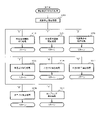
図7は、演出制御プロセス処理として、図6のステップS76にて実行される処理の一例を示すフローチャートである。図7に示す演出制御プロセス処理において、演出制御用CPU120は、まず、先読予告設定処理を実行する(ステップS161)。先読予告設定処理では、例えば、主基板11から送信された始動入賞時の演出制御コマンドに基づいて、先読み予告演出を実行するための判定や決定、設定などが行われる。また、当該演出制御コマンドから特定される保留記憶数に基づき保留表示を表示するための処理が実行される。
FIG. 7 is a flowchart showing an example of the process executed in step S76 of FIG. 6 as the effect control process process. In the effect control process process shown in FIG. 7, the
ステップS161の処理を実行した後、演出制御用CPU120は、例えばRAM122に設けられた演出プロセスフラグの値に応じて、以下のようなステップS170~S177の処理のいずれかを選択して実行する。
After executing the process of step S161, the
ステップS170の可変表示開始待ち処理は、演出プロセスフラグの値が“0”(初期値)のときに実行される処理である。この可変表示開始待ち処理は、主基板11から可変表示の開始を指定するコマンドなどを受信したか否かに基づき、画像表示装置5における飾り図柄の可変表示を開始するか否かを判定する処理などを含んでいる。画像表示装置5における飾り図柄の可変表示を開始すると判定された場合、演出プロセスフラグの値を“1”に更新し、可変表示開始待ち処理を終了する。
The variable display start waiting process in step S170 is a process executed when the value of the effect process flag is “0” (initial value). This variable display start waiting process is a process of determining whether or not to start variable display of the decorative symbol on the
ステップS171の可変表示開始設定処理は、演出プロセスフラグの値が“1”のときに実行される処理である。この可変表示開始設定処理では、演出制御コマンドにより特定される表示結果や変動パターンに基づいて、飾り図柄の可変表示の表示結果(確定飾り図柄)、飾り図柄の可変表示の態様、リーチ演出や各種予告演出などの各種演出の実行の有無やその態様や実行開始タイミングなどを決定する。そして、その決定結果等を反映した演出制御パターン(表示制御部123に演出の実行を指示するための制御データの集まり)を設定する。その後、設定した演出制御パターンに基づいて、飾り図柄の可変表示の実行開始を表示制御部123に指示し、演出プロセスフラグの値を“2”に更新し、可変表示開始設定処理を終了する。表示制御部123は、飾り図柄の可変表示の実行開始の指示により、画像表示装置5において、飾り図柄の可変表示を開始させる。
The variable display start setting process in step S171 is a process executed when the value of the effect process flag is “1”. In this variable display start setting process, the display result of the variable display of the decorative symbol (fixed decorative symbol), the mode of the variable display of the decorative symbol, the reach effect, and various types are based on the display result and the variation pattern specified by the effect control command. It is determined whether or not various effects such as a notice effect are executed, the mode thereof, and the execution start timing. Then, an effect control pattern (a collection of control data for instructing the
ステップS172の可変表示中演出処理は、演出プロセスフラグの値が“2”のときに実行される処理である。この可変表示中演出処理において、演出制御用CPU120は、表示制御部123を指示することで、ステップS171にて設定された演出制御パターンに基づく演出画像を画像表示装置5の表示画面に表示させることや、可動体32を駆動させること、音声制御基板13に対する指令(効果音信号)の出力によりスピーカ8L、8Rから音声や効果音を出力させること、ランプ制御基板14に対する指令(電飾信号)の出力により遊技効果ランプ9や装飾用LEDを点灯/消灯/点滅させることといった、飾り図柄の可変表示中における各種の演出制御を実行する。こうした演出制御を行った後、例えば演出制御パターンから飾り図柄の可変表示終了を示す終了コードが読み出されたこと、あるいは、主基板11から確定飾り図柄を停止表示させることを指定するコマンドを受信したことなどに対応して、飾り図柄の表示結果となる確定飾り図柄を停止表示させる。確定飾り図柄を停止表示したときには、演出プロセスフラグの値が“3”に更新され、可変表示中演出処理は終了する。
The variable display effect process in step S172 is a process executed when the value of the effect process flag is “2”. In this variable display effect processing, the
ステップS173の特図当り待ち処理は、演出プロセスフラグの値が“3”のときに実行される処理である。この特図当り待ち処理において、演出制御用CPU120は、主基板11から大当り遊技状態又は小当り遊技状態を開始することを指定する演出制御コマンドの受信があったか否かを判定する。そして、大当り遊技状態又は小当り遊技状態を開始することを指定する演出制御コマンドを受信したきに、そのコマンドが大当り遊技状態の開始を指定するものであれば、演出プロセスフラグの値を“6”に更新する。これに対して、そのコマンドが小当り遊技状態の開始を指定するものであれば、演出プロセスフラグの値を小当り中演出処理に対応した値である“4”に更新する。また、大当り遊技状態又は小当り遊技状態を開始することを指定するコマンドを受信せずに、当該コマンドの受信待ち時間が経過したときには、特図ゲームにおける表示結果が「ハズレ」であったと判定して、演出プロセスフラグの値を初期値である“0”に更新する。演出プロセスフラグの値を更新すると、特図当り待ち処理を終了する。
The special figure hit waiting process in step S173 is a process executed when the value of the effect process flag is “3”. In this special figure hit waiting process, the
ステップS174の小当り中演出処理は、演出制御プロセスフラグの値が“4”のときに実行される処理である。この小当り中演出処理において、演出制御用CPU120は、例えば小当り遊技状態における演出内容に対応した演出制御パターン等を設定し、その設定内容に基づく小当り遊技状態における各種の演出制御を実行する。また、小当り中演出処理では、例えば主基板11から小当り遊技状態を終了することを指定するコマンドを受信したことに対応して、演出プロセスフラグの値を小当り終了演出に対応した値である“5”に更新し、小当り中演出処理を終了する。
The small hit medium effect process in step S174 is a process executed when the value of the effect control process flag is “4”. In this small hit medium effect process, the
ステップS175の小当り終了演出処理は、演出制御プロセスフラグの値が“5”のときに実行される処理である。この小当り終了演出処理において、演出制御用CPU120は、例えば小当り遊技状態の終了などに対応した演出制御パターン等を設定し、その設定内容に基づく小当り遊技状態の終了時における各種の演出制御を実行する。その後、演出プロセスフラグの値を初期値である“0”に更新し、小当り終了演出処理を終了する。
The small hit end effect process in step S175 is a process executed when the value of the effect control process flag is “5”. In this small hit end effect process, the
ステップS176の大当り中演出処理は、演出プロセスフラグの値が“6”のときに実行される処理である。この大当り中演出処理において、演出制御用CPU120は、例えば大当り遊技状態における演出内容に対応した演出制御パターン等を設定し、その設定内容に基づく大当り遊技状態における各種の演出制御を実行する。また、大当り中演出処理では、例えば主基板11から大当り遊技状態を終了することを指定するコマンドを受信したことに対応して、演出制御プロセスフラグの値をエンディング演出処理に対応した値である“7”に更新し、大当り中演出処理を終了する。
The big hit middle effect process in step S176 is a process executed when the value of the effect process flag is “6”. In this big hit middle effect process, the
ステップS177のエンディング演出処理は、演出プロセスフラグの値が“7”のときに実行される処理である。このエンディング演出処理において、演出制御用CPU120は、例えば大当り遊技状態の終了などに対応した演出制御パターン等を設定し、その設定内容に基づく大当り遊技状態の終了時におけるエンディング演出の各種の演出制御を実行する。その後、演出プロセスフラグの値を初期値である“0”に更新し、エンディング演出処理を終了する。
The ending effect process of step S177 is a process executed when the value of the effect process flag is “7”. In this ending effect processing, the
(基本説明の変形例)
この発明は、上記基本説明で説明したパチンコ遊技機1に限定されず、本発明の趣旨を逸脱しない範囲で、様々な変形及び応用が可能である。
(Modified example of basic explanation)
The present invention is not limited to the
上記基本説明のパチンコ遊技機1は、入賞の発生に基づいて所定数の遊技媒体を景品として払い出す払出式遊技機であったが、遊技媒体を封入し入賞の発生に基づいて得点を付与する封入式遊技機であってもよい。
The
特別図柄の可変表示中に表示されるものは1種類の図柄(例えば、「-」を示す記号)だけで、当該図柄の表示と消灯とを繰り返すことによって可変表示を行うようにしてもよい。さらに可変表示中に当該図柄が表示されるものも、可変表示の停止時には、当該図柄が表示されなくてもよい(表示結果としては「-」を示す記号が表示されなくてもよい)。 Only one type of symbol (for example, a symbol indicating "-") is displayed during the variable display of the special symbol, and the variable display may be performed by repeating the display and extinguishing of the symbol. Further, even if the symbol is displayed during the variable display, the symbol may not be displayed when the variable display is stopped (the symbol indicating "-" may not be displayed as the display result).
上記基本説明では、遊技機としてパチンコ遊技機1を示したが、メダルが投入されて所定の賭け数が設定され、遊技者による操作レバーの操作に応じて複数種類の図柄を回転させ、遊技者によるストップボタンの操作に応じて図柄を停止させたときに停止図柄の組合せが特定の図柄の組み合わせになると、所定数のメダルが遊技者に払い出されるゲームを実行可能なスロット機(例えば、ビッグボーナス、レギュラーボーナス、RT、AT、ART、CZ(以下、ボーナス等)のうち1以上を搭載するスロット機)にも本発明を適用可能である。
In the above basic explanation, the
本発明を実現するためのプログラム及びデータは、パチンコ遊技機1に含まれるコンピュータ装置などに対して、着脱自在の記録媒体により配布・提供される形態に限定されるものではなく、予めコンピュータ装置などの有する記憶装置にインストールしておくことで配布される形態を採っても構わない。さらに、本発明を実現するためのプログラム及びデータは、通信処理部を設けておくことにより、通信回線等を介して接続されたネットワーク上の、他の機器からダウンロードすることによって配布する形態を採っても構わない。
The program and data for realizing the present invention are not limited to the form of being distributed and provided by a detachable recording medium to the computer device included in the
そして、ゲームの実行形態も、着脱自在の記録媒体を装着することにより実行するものだけではなく、通信回線等を介してダウンロードしたプログラム及びデータを、内部メモリ等に一旦格納することにより実行可能とする形態、通信回線等を介して接続されたネットワーク上における、他の機器側のハードウェア資源を用いて直接実行する形態としてもよい。さらには、他のコンピュータ装置等とネットワークを介してデータの交換を行うことによりゲームを実行するような形態とすることもできる。 The execution mode of the game is not limited to the one executed by attaching a detachable recording medium, but can be executed by temporarily storing the program and data downloaded via the communication line or the like in the internal memory or the like. It may be executed directly by using the hardware resources of other devices on the network connected via a communication line or the like. Furthermore, it is also possible to execute a game by exchanging data with another computer device or the like via a network.
なお、本明細書において、演出の実行割合などの各種割合の比較の表現(「高い」、「低い」、「異ならせる」などの表現)は、一方が「0%」の割合であることを含んでもよい。例えば、一方が「0%」の割合で、他方が「100%」の割合又は「100%」未満の割合であることも含む。 In addition, in this specification, one of the expressions for comparison of various ratios such as the execution ratio of the production (expressions such as "high", "low", and "differentiate") is "0%". It may be included. For example, one may have a percentage of "0%" and the other may have a percentage of "100%" or less than "100%".
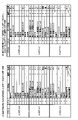
(特徴部31AKに関する説明)
次に、本実施の形態の特徴部31AKについて説明する。図8は、本実施の形態のパチンコ遊技機1における変動パターンやリーチの種類を説明するための図である。図8(A)に示すように、本実施の形態では、飾り図柄の可変表示の態様がリーチ態様とならずに表示結果が「ハズレ」となる非リーチハズレの変動パターンPA1-1、PA1-2、飾り図柄の可変表示の態様がリーチ態様となって表示結果が「ハズレ」となるリーチハズレの変動パターンPA2-1~PA2-6、PA3-1~PA3-4等、表示結果が「大当り」となる変動パターンPB2-1~PB2-6、PB3-1~PB3-4等が用意されている。
(Explanation of feature section 31AK)
Next, the feature portion 31AK of the present embodiment will be described. FIG. 8 is a diagram for explaining a variation pattern and a type of reach in the
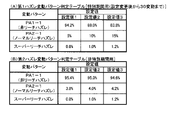
また、図8(B)に示すように、本実施の形態では、ノーマルリーチ、スーパーリーチA~Eといったリーチ演出が実行されるようになっている。この実施の形態では、リーチ演出は、大当り状態に制御されることを示唆する示唆演出とも称される。各リーチが実行されたときの信頼度(大当り信頼度)は、図8(B)の黒色の星の数で表すように、ノーマルリーチ<スーパーリーチE<スーパーリーチD<スーパーリーチC<スーパーリーチB<スーパーリーチAの順番に高くなっている。なお、大当りとなることが確定するリーチを設けてもよい。 Further, as shown in FIG. 8B, in the present embodiment, reach effects such as normal reach and super reach A to E are executed. In this embodiment, the reach effect is also referred to as a suggestion effect suggesting that the jackpot state is controlled. The reliability (big hit reliability) when each reach is executed is represented by the number of black stars in FIG. 8 (B). Normal reach <Super reach E <Super reach D <Super reach C <Super reach B <The order is higher in the order of Super Reach A. In addition, a reach that is determined to be a big hit may be provided.
この実施の形態では、スーパーリーチはノーマルリーチを経由して実行されるようになっている。また、スーパーリーチのリーチ演出中に、より信頼度の高いリーチに発展(昇格)する発展演出が実行される場合がある。図8(A)に示す変動パターンPA3-1~PA3-4等、変動パターンPB3-1~PB3-4等が、発展演出が実行されることに対応した変動パターンとなっている。なお、図8(A)では、信頼度が一段階上のスーパーリーチに発展する変動パターンが示されているが、信頼度が二段階以上発展する変動パターンも設けられる。また、発展演出が複数回実行される変動パターンを設けてもよい。 In this embodiment, the super reach is performed via the normal reach. In addition, during the reach production of Super Reach, a development production that develops (promotes) to a more reliable reach may be executed. The fluctuation patterns PA3-1 to PA3-4 and the like shown in FIG. 8A and the fluctuation patterns PB3-1 to PB3-4 and the like are fluctuation patterns corresponding to the execution of the development effect. In addition, although FIG. 8A shows a fluctuation pattern in which the reliability develops to a super reach one step higher, a fluctuation pattern in which the reliability develops by two or more steps is also provided. Further, a variation pattern in which the development effect is executed a plurality of times may be provided.
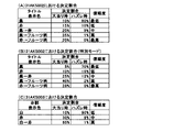
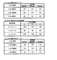
この実施の形態では、信頼度が最も低いノーマルリーチ以外では、リーチ成立後の所定タイミングにおいて、そのリーチのタイトルが報知されるようになっている。図8(B)に示すように、リーチの種類によってタイトルの報知態様が異なっている。具体的には、スーパーリーチの中で最も信頼度の低いスーパーリーチEは、表示のみでリーチのタイトルが報知され、それ以外のスーパーリーチは、表示及び音声によりタイトルが報知される。このように、信頼度の高いリーチの方が信頼度の低いリーチより多くの演出装置によりタイトルの報知が実行されるようになっている。これにより、遊技者の期待感を効果的に煽ることができ演出効果が向上する。なお、タイトルの報知態様は、信頼度によってまたは信頼度によらず任意に変更してもよい。また、同じリーチ演出においても、実際の表示結果等に応じて報知態様を異ならせてもよい。また、リーチの種類によってタイトル文字のフォント(ゴシック体、明朝体等)や書体(行書、楷書等)を異ならせてもよい。 In this embodiment, except for the normal reach having the lowest reliability, the title of the reach is notified at a predetermined timing after the reach is established. As shown in FIG. 8B, the notification mode of the title differs depending on the type of reach. Specifically, Super Reach E, which has the lowest reliability among Super Reach, is notified of the title of the reach only by display, and other Super Reach is notified of the title by display and voice. In this way, the title is notified by more production devices in the reach with high reliability than in the reach with low reliability. As a result, the expectation of the player can be effectively fueled, and the staging effect is improved. The mode of notifying the title may be arbitrarily changed depending on the reliability or regardless of the reliability. Further, even in the same reach effect, the notification mode may be different depending on the actual display result and the like. In addition, the font (Gothic typeface, Mincho typeface, etc.) and typeface (line book, regular script, etc.) of the title character may be different depending on the type of reach.
リーチのタイトルの報知(タイトル報知)とは、リーチの名称といったタイトルそのものを示すものに限定されず、リーチ演出で登場するキャラクタの名称、リーチ演出の演出内容等を示すものであってもよい。 The notification of the title of the reach (title notification) is not limited to the one indicating the title itself such as the name of the reach, and may indicate the name of the character appearing in the reach production, the production content of the reach production, and the like.
(特徴部31AKの演出動作例)
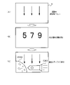
続いて、本実施の形態における演出動作例について説明する。以下の演出動作は、主基板11から送信される演出制御コマンドに基づいて、演出制御用CPU120が演出制御プロセス処理を実行することで実行される。図9、図10は、本実施の形態におけるスーパーリーチの演出動作例を示す図である。図9(A)は、画像表示装置5の「左」、「中」、「右」の各飾り図柄表示エリア5L、5C、5Rにおいて飾り図柄の可変表示が実行されていることを示している。その後、例えば、図9(B)に示すように、「左」及び「右」に7の数字を示す飾り図柄が停止してリーチ態様となる。その後はリーチの種類に応じて演出が分岐する。
(Example of staging operation of feature unit 31AK)
Subsequently, an example of the effect operation in the present embodiment will be described. The following staging operation is executed by the
(スーパーリーチA)
スーパーリーチAとなる場合には、図9(C)に示すように、画像表示装置5に味方キャラであるキャラクタ31AK001が表示されてリーチ演出が開始される。ここでは、例えばキャラクタ31AK001を使用したアニメーション等が表示される。スーパーリーチのリーチ演出(スーパーリーチ演出ともいう)の導入部分が終了する等、スーパーリーチ演出が開始されてから所定期間経過すると、図9(D)に示すように、画像表示装置5の画面全体にスーパーリーチAのタイトル31AK002(ここでは「SPリーチA」の文字)が表示されるとともに、スピーカ8からリーチのタイトル名に対応する音声(ここでは「スーパーリーチA」)が出力されることで、スーパーリーチAのタイトルが報知される。その後、スーパーリーチAのタイトル31AK002が消去され、図9(E)に示すように、敵キャラであるキャラクタ31AK003が表示され、キャラクタ31AK001のセリフ31AK004が表示されたり、キャラクタ31AK001とキャラクタ31AK003とが対決するスーパーリーチAのリーチ演出の後続部分が実行される。キャラクタ同士が対決する演出をバトル演出ともいい、バトル演出において味方キャラが勝利すると大当りとなり、味方キャラが敗北するとハズレとなる。
(Super Reach A)
In the case of Super Reach A, as shown in FIG. 9C, the character 31AK001, which is a ally character, is displayed on the
なお、スーパーリーチ演出中に画像表示装置5にセリフを表示するときに、スピーカ8からセリフに対応する音声が出力されるようにしてもよい。また、セリフは図9(E)に示すように吹き出しに表示することに限定されず、画像表示装置5の下部等に字幕で表示するようにしてもよい。
When displaying the dialogue on the
(スーパーリーチB)
スーパーリーチBとなる場合には、図9(C)に示すように、画像表示装置5にキャラクタ31AK001が表示されてリーチ演出が開始される。ここでは、例えばキャラクタ31AK001を使用したアニメーション等が表示される。スーパーリーチ演出の導入部分が終了する等、スーパーリーチ演出が開始されてから所定期間経過すると、図9(F)に示すように、画像表示装置5の画面全体にスーパーリーチBのタイトル31AK005(ここでは「SPリーチB」の文字)が表示されるとともに、スピーカ8からリーチのタイトル名に対応する音声(ここでは「スーパーリーチB」)が出力されることで、スーパーリーチBのタイトルが報知される。その後、スーパーリーチBのタイトル31AK005が消去され、図9(G)に示すように、敵キャラであるキャラクタ31AK006が表示され、キャラクタ31AK001のセリフ31AK004が表示されたり、キャラクタ31AK001とキャラクタ31AK006とが対決するスーパーリーチBのリーチ演出の後続部分が実行される。
(Super Reach B)
In the case of super reach B, as shown in FIG. 9C, the character 31AK001 is displayed on the
このように、スーパーリーチAとスーパーリーチBとでは、スーパーリーチ演出が開始されてから所定期間経過したときにリーチのタイトルが報知されるようになっている。このようにすることで、スーパーリーチ演出の導入部分等を遊技者に見せた後にタイトルを報知できるので、タイトル報知の演出効果を高めることができる。 As described above, in the super reach A and the super reach B, the title of the reach is notified when a predetermined period has elapsed from the start of the super reach effect. By doing so, the title can be notified after the introduction portion of the super reach effect is shown to the player, so that the effect of the title notification can be enhanced.
また、スーパーリーチA(図9(C)→(D)→(E)・・・)とスーパーリーチB(図9(C)→(F)→(G)・・・)とでは、タイトルが報知されるまでの導入部分においては、共通の演出態様でスーパーリーチ演出が実行されるようになっている(図9(C))。このようにすることで、スーパーリーチ演出が開始されてからいずれのスーパーリーチとなるか、いずれのタイトルが報知されるかに遊技者を注目させることができる。スーパーリーチAとスーパーリーチBとにおいて、タイトルが報知されるまでの演出態様を完全に共通にすることに限定されず、演出を注視すればいずれのスーパーリーチとなるかを判別できる等、少なくとも一部を共通の演出態様にするようにしてもよい。例えば、スーパーリーチAとスーパーリーチBとの導入部分において、その後に報知されるタイトルに関連する態様でスーパーリーチ演出(例えば敵キャラを表示したり敵キャラを示唆するような演出)を実行するようにしてもよい。このようにすることで、演出効果が向上し、遊技者が演出に注目するようになる。このように、いずれのスーパーリーチとなるかを特定可能にしてからタイトル報知を実行するようにしてもよい。 Further, in Super Reach A (FIG. 9 (C) → (D) → (E) ...) and Super Reach B (FIG. 9 (C) → (F) → (G) ...), the title is In the introduction part until the notification is made, the super reach effect is executed in a common effect mode (FIG. 9 (C)). By doing so, it is possible to draw the player's attention to which super reach will be achieved after the super reach production is started and which title will be notified. Super Reach A and Super Reach B are not limited to completely sharing the production mode until the title is announced, and it is possible to determine which Super Reach will be achieved by paying close attention to the production. The parts may be made into a common production mode. For example, in the introduction part of Super Reach A and Super Reach B, a super reach effect (for example, an effect of displaying an enemy character or suggesting an enemy character) is executed in a manner related to the title notified thereafter. You may do it. By doing so, the effect of the effect is improved, and the player pays attention to the effect. In this way, the title notification may be executed after making it possible to specify which super reach will be achieved.
(スーパーリーチD)
スーパーリーチDとなる場合には、図9(H)に示すように、画像表示装置5の中央の一部にスーパーリーチDのタイトル31AK007(ここでは「SPリーチD」の文字)が表示されるとともに、スピーカ8からリーチのタイトル名に対応する音声(ここでは「敵を倒せ」)が出力されることで、スーパーリーチDのタイトルが報知される。このように、スーパーリーチDでは、スーパーリーチ演出の開始時にタイトルが報知されるようになっている。また、タイトル31AK007の下には、当該リーチの期待度を示唆する期待度示唆表示31AK008が表示される。期待度は、図9(H)に示すように、黒い星の数で表される。ここで、期待度とは大当りとなる期待度であるが、リーチの大当り信頼度と完全に一致していなくてもよい。
(Super Reach D)
In the case of super reach D, as shown in FIG. 9 (H), the title 31AK007 of super reach D (here, the character “SP reach D”) is displayed in a part of the center of the
なお、スーパーリーチDの音声による報知は、タイトル名をそのまま報知するのではなく、リーチの内容を報知するようになっている。このように、この実施の形態では、リーチの種類によって音声によるタイトル報知の報知態様を異ならせている。これにより、タイトル報知の報知態様が多彩になり、興趣が向上する。 It should be noted that the voice notification of Super Reach D does not notify the title name as it is, but notifies the content of the reach. As described above, in this embodiment, the notification mode of the title notification by voice is different depending on the type of reach. As a result, the notification mode of the title notification becomes various and the interest is improved.
スーパーリーチDにおいてタイトルが報知された後には、図9(I)に示すように、画像表示装置5にキャラクタ31AK001が表示される。このとき、タイトル31AK007及び期待度示唆表示31AK008は、画像表示装置5の右上部分等に縮小して表示され続ける。このようにすることで、リーチ演出中にも遊技者がリーチの期待度を把握することができる。なお、図9(I)では、図9(C)(スーパーリーチA、スーパーリーチB)と共通の演出内容が示されているが、スーパーリーチD専用のスーパーリーチ演出が実行されてもよい。
After the title is notified in Super Reach D, the character 31AK001 is displayed on the
その後、図9(J)に示すように、敵キャラであるキャラクタ31AK009が表示され、キャラクタ31AK001のセリフ31AK004が表示されたり、キャラクタ31AK001とキャラクタ31AK009とが対決するスーパーリーチDのリーチ演出が実行される。 After that, as shown in FIG. 9 (J), the character 31AK009, which is an enemy character, is displayed, the dialogue 31AK004 of the character 31AK001 is displayed, and the reach effect of the super reach D in which the character 31AK001 and the character 31AK009 confront each other is executed. To.
(スーパーリーチE)
スーパーリーチEとなる場合には、図10(A)に示すように、画像表示装置5の左上の一部にスーパーリーチEのタイトル31AK010(ここでは「SPリーチE」の文字)が表示されることで、スーパーリーチEのタイトルが報知される。なお、スーパーリーチEでは、音声によるタイトルの報知が行われない。また、タイトル31AK010の表示と合わせて、キャラクタ31AK001と敵キャラであるキャラクタ31AK011とが表示され、キャラクタ31AK001のセリフ31AK004が表示されたり、キャラクタ31AK001とキャラクタ31AK011とが対決するスーパーリーチEのリーチ演出が実行される。このように、スーパーリーチEでは、リーチ演出の進行と合わせてタイトルが報知されるようになっている。スーパーリーチEでは、リーチ演出中にタイトル31AK010が表示され続ける。
(Super Reach E)
In the case of Super Reach E, as shown in FIG. 10A, the title 31AK010 of Super Reach E (here, the character “SP Reach E”) is displayed in a part of the upper left of the
大当り信頼度の低いスーパーリーチEのリーチ演出では、リーチ演出の進行を止めずにタイトル報知を行うことで、遊技者に過度な期待感を与えることを防止できる。これに対して、スーパーリーチA、スーパーリーチB、スーパーリーチDのリーチ演出では、リーチ演出の進行を停止してタイトル報知を行うようになっている(図9(D)、(F)、(H))。このようにすることで、スーパーリーチ演出に応じたタイトル報知を実行でき演出効果が向上する。なお、スーパーリーチA、スーパーリーチB、スーパーリーチDといったスーパーリーチ演出においてもリーチの進行を停止せずにタイトル報知を行うようにしてもよい。また、この実施の形態とは逆に、大当り信頼度の高いスーパーリーチのリーチ演出では、リーチ演出の進行を止めずにタイトル報知を行うようにしてもよい。大当り信頼度の低いスーパーリーチのリーチ演出では、リーチ演出の進行を停止してタイトル報知を行うようにしてもよい。 In the reach production of Super Reach E, which has low jackpot reliability, it is possible to prevent the player from giving an excessive sense of expectation by notifying the title without stopping the progress of the reach production. On the other hand, in the reach production of Super Reach A, Super Reach B, and Super Reach D, the progress of the reach production is stopped and the title is notified (FIGS. 9 (D), (F), (Fig. 9). H)). By doing so, the title notification according to the super reach effect can be executed, and the effect of the effect is improved. Even in the super reach production such as super reach A, super reach B, and super reach D, the title may be notified without stopping the progress of the reach. Further, contrary to this embodiment, in the reach production of the super reach with high jackpot reliability, the title notification may be performed without stopping the progress of the reach production. In the reach production of super reach with low jackpot reliability, the progress of the reach production may be stopped and the title notification may be performed.
(タイトルの報知タイミング)
以上のように、この実施の形態では、スーパーリーチA及びスーパーリーチBにおいては、スーパーリーチ演出開始後所定期間経過してからタイトルが報知され、スーパーリーチD及びスーパーリーチEにおいては、スーパーリーチ演出開始時にタイトルが報知されるようになっている。このようにすることで、リーチ演出に応じたタイトル報知を実行でき演出効果が向上する。なお、この実施の形態では、大当り信頼度の高いスーパーリーチA及びスーパーリーチBにおいては、スーパーリーチ演出開始後所定期間経過してからタイトルが報知され、大当り信頼度の低いスーパーリーチD及びスーパーリーチEにおいては、スーパーリーチ演出開始時にタイトルが報知されるようになっていたが、大当り信頼度の高いリーチの場合にスーパーリーチ演出開始時にタイトルが報知され、大当り信頼度の低いリーチの場合にスーパーリーチ演出後所定期間経過してからタイトルが報知されるようにしてもよい。
(Title notification timing)
As described above, in this embodiment, in Super Reach A and Super Reach B, the title is notified after a predetermined period has elapsed from the start of the Super Reach production, and in Super Reach D and Super Reach E, the Super Reach production is performed. The title is notified at the start. By doing so, the title notification according to the reach effect can be executed, and the effect of the effect is improved. In this embodiment, in Super Reach A and Super Reach B having high jackpot reliability, the title is notified after a predetermined period has elapsed from the start of the super reach production, and Super Reach D and Super Reach having low jackpot reliability are notified. In E, the title was notified at the start of the super reach production, but in the case of a reach with a high jackpot reliability, the title is notified at the start of the super reach production, and in the case of a reach with a low jackpot reliability, the super is announced. The title may be notified after a predetermined period has elapsed after the reach production.
(タイトルの表示領域)
また、この実施の形態では、スーパーリーチA及びスーパーリーチBにおいては、画像表示装置5の画面全体(第1領域)においてタイトルが報知され、スーパーリーチD及びスーパーリーチEにおいては、画像表示装置5の画面の一部(第2領域)においてタイトルが報知される。このようにすることで、リーチ演出に応じたタイトル報知を実行でき演出効果が向上する。特に、大当り信頼度の高いリーチである場合には、信頼度の低いリーチである場合よりも広い表示領域でタイトル報知が実行されるので効果的なタイトル報知が可能になる。なお、画像表示装置5の画面全体におけるタイトル報知とは、画面いっぱいに収まるサイズでタイトルが表示されるものであってもよいし、背景全体をタイトル報知用の背景としてそこにタイトルが表示されるもの(画面全体を使用したタイトル報知)等であってもよい。また、スーパーリーチAとスーパーリーチBとでタイトル報知を行う表示領域を異ならせてもよいし、スーパーリーチDとスーパーリーチEとでタイトル報知を行う表示領域を異ならせてもよい。
(Title display area)
Further, in this embodiment, in Super Reach A and Super Reach B, the title is notified on the entire screen (first area) of the
リーチ演出に応じてタイトル報知を行う表示領域を異ならせる方法は、この実施の形態の例に限定されず、リーチ演出に応じてタイトル報知を行う表示領域を任意に異ならせてもよい。例えば、大当り信頼度の高いリーチである場合には、信頼度の低いリーチである場合よりも狭い表示領域でタイトル報知が実行されてもよい。また、リーチ演出に応じてタイトル報知を行う表示領域を異ならせる場合において、この実施の形態のように表示面積を異ならせてもよいし、表示させる場所を異ならせてもよい。 The method of differentiating the display area for performing the title notification according to the reach effect is not limited to the example of this embodiment, and the display area for performing the title notification may be arbitrarily different according to the reach effect. For example, in the case of reach with high jackpot reliability, title notification may be executed in a narrower display area than in the case of reach with low reliability. Further, when the display area for performing the title notification is different according to the reach effect, the display area may be different or the display place may be different as in this embodiment.
(期待度示唆表示)
この実施の形態では、大当り信頼度の高いスーパーリーチA及びスーパーリーチBにおけるタイトル報知では、期待度示唆表示を表示せずに、スーパーリーチA及びスーパーリーチBよりも大当り信頼度の低いスーパーリーチDにおけるタイトル報知では、期待度示唆表示を表示するようにしていた。このようにすることで、演出がくどくなることを防止できる。また、スーパーリーチDよりも大当り信頼度の低いスーパーリーチEにおけるタイトル報知では、期待度示唆表示を表示しないようになっていた。このようにすることで、信頼度の低いリーチにおいて信頼度が低いことを示す期待度示唆表示が表示されることで遊技者が期待感を失うことを防止できる。なお、スーパーリーチA、スーパーリーチB、スーパーリーチEの少なくとも一部において期待度示唆表示を表示するようにしてもよい。
(Expectation suggestion display)
In this embodiment, in the title notification in Super Reach A and Super Reach B having high jackpot reliability, the expectation suggestion display is not displayed, and Super Reach D having lower jackpot reliability than Super Reach A and Super Reach B is not displayed. In the title notification in, the expectation degree suggestion display was displayed. By doing so, it is possible to prevent the production from becoming dull. Further, in the title notification in Super Reach E, which has a lower jackpot reliability than Super Reach D, the expectation degree suggestion display is not displayed. By doing so, it is possible to prevent the player from losing the sense of expectation by displaying the expectation degree suggestion display indicating that the reliability is low in the reach with low reliability. In addition, the expectation degree suggestion display may be displayed in at least a part of Super Reach A, Super Reach B, and Super Reach E.
なお期待度示唆表示は、図9(H)等に示すように、黒い星の数によって示すものに限定されず、メーターやゲージにより期待度を示唆するようにしてもよいし、期待度に対応した数値を表示するようにしてもよい。また、図9(H)等に示すように、黒い星の数によって示す場合において、半個相当(半分)の黒い星を表示可能ようにして、期待度の段階数を増やしてもよい。 As shown in FIG. 9 (H), the expectation degree suggestion display is not limited to the one indicated by the number of black stars, and the expectation degree may be suggested by a meter or a gauge, and corresponds to the expectation degree. The numerical value may be displayed. Further, as shown in FIG. 9H or the like, when the number of black stars is used, half of the black stars may be displayed so that the number of stages of expectation may be increased.
(タイトルの表示終了タイミング)
また、この実施の形態では、スーパーリーチA及びスーパーリーチBにおいては、タイトルが表示された後、タイトルが消去されてスーパーリーチ演出が実行される。これにより、スーパーリーチA及びスーパーリーチBにおいては、リーチ演出に注目させることができる。また、スーパーリーチD及びスーパーリーチEにおいては、タイトルが表示された後、後述の決め演出が実行されるまでタイトルが表示され続ける。これにより、スーパーリーチD及びスーパーリーチEにおいては、スーパーリーチ演出中もリーチの種類を把握することができる。また、以上のようにすることで、リーチ演出に応じたタイトル報知を実行でき演出効果が向上する。なお、タイトルの表示終了タイミングは、いずれであっても演出効果の向上を図れるため、任意に変更してもよい。
(Title display end timing)
Further, in this embodiment, in the super reach A and the super reach B, after the title is displayed, the title is erased and the super reach effect is executed. As a result, in Super Reach A and Super Reach B, attention can be paid to the reach effect. Further, in Super Reach D and Super Reach E, after the title is displayed, the title is continuously displayed until the determined effect described later is executed. As a result, in Super Reach D and Super Reach E, the type of reach can be grasped even during the super reach production. Further, by doing the above, the title notification according to the reach effect can be executed and the effect of the effect is improved. It should be noted that the display end timing of the title may be arbitrarily changed in any case because the effect of the effect can be improved.
なお、ここではスーパーリーチCのリーチ演出の演出動作については省略するが、例えば大当り信頼度に応じたタイトル報知や期待度示唆表示が実行されればよい。 Although the effect of the reach effect of the super reach C is omitted here, for example, the title notification and the expectation degree suggestion display according to the jackpot reliability may be executed.
(決め演出)
各リーチ演出が実行されてから、表示結果を導出するタイミング(可変表示の終盤)になると、表示結果が「大当り」となるか否かを報知するための決め演出が実行される。決め演出には、表示結果が「大当り」となることを示す決め演出と、表示結果が「ハズレ」となることを示す決め演出と、が含まれる。この実施の形態では、図10(B)に示すように、画像表示装置5に画像31AK012が表示される決め演出が実行される。その後、表示結果が「大当り」であれば、図10(C)に示すように、味方キャラが勝利したことを示す画像31AK013が表示され、図10(D)に示すように、大当り組合せとなる確定飾り図柄が導出される。なお、表示結果が「ハズレ」であれば、味方キャラが敗北したことを示す画像が表示され、リーチハズレ組合せとなる確定飾り図柄が導出される。
(Decisive production)
After each reach effect is executed, when the timing for deriving the display result (the final stage of the variable display) is reached, a decision effect for notifying whether or not the display result becomes a "big hit" is executed. The deciding effect includes a deciding effect indicating that the display result is "big hit" and a deciding effect indicating that the display result is "missing". In this embodiment, as shown in FIG. 10B, a determination effect of displaying the image 31AK012 on the
この実施の形態では、リーチ演出中も継続してタイトルを報知する場合でも、決め演出が実行される前にタイトルの報知を終了するようになっている。これにより、決め演出に注目させることができ、また、メリハリのあるタイトル報知を実行できる。 In this embodiment, even if the title is continuously notified even during the reach production, the notification of the title is terminated before the determined production is executed. As a result, it is possible to draw attention to the deciding effect, and it is possible to execute a sharp title notification.
図9、図10に示した演出動作例では、スーパーリーチのリーチ演出中は画像表示装置5の右下部分で飾り図柄を縮小して可変表示を実行するようになっていたが、リーチ演出中の飾り図柄の表示のさせ方は任意でよい。例えば、リーチ演出中は飾り図柄が表示されなくてもよいし、リーチ演出の種類によって表示態様(大きさ、位置、濃淡、数等)を異ならせてもよい。
In the effect operation examples shown in FIGS. 9 and 10, during the reach effect of the super reach, the decorative pattern is reduced in the lower right portion of the
なお、画像表示装置5に保留表示、アクティブ表示、可変表示中に常駐表示されるキャラクタ、携帯連動関連の表示を表示する場合、スーパーリーチのリーチ演出中はリーチ演出に注目させるために適宜非表示としてもよい。その際に、スーパーリーチEといった低信頼度のリーチ演出中には、これらの表示を表示したままにするようにしてもよい。このようにすることで、低信頼度のリーチ演出により遊技者を過度に期待させてしまうことを防止できるとともに、高信頼度のリーチ演出ではリーチ演出に注目させることができる。
When the
(発展演出)
続いて、発展演出が実行される場合の演出動作例について説明する。図11(A)に示すように、スーパーリーチDのリーチ演出が実行されている(スーパーリーチDのタイトル報知が実行されている)ときに発展演出が実行される場合、図11(B)に示すように、リーチ演出が中断して画面が裂けるような演出が実行される。その後、スーパーリーチAに発展する場合には、図11(C)に示すように、スーパーリーチAのタイトルが報知され、スーパーリーチAのリーチ演出が実行される。スーパーリーチBに発展する場合には、図11(D)に示すように、スーパーリーチBのタイトルが報知され、スーパーリーチのリーチ演出が実行される。このように、発展演出が実行された場合には、発展元のリーチのタイトル報知から発展先のリーチのタイトル報知に切り替えられるで、いずれのリーチに発展したかがわかりやすくなる。図11に示すように、発展先のリーチが表示及び音声によりタイトル報知を行うリーチである場合には、表示及び音声によるタイトル報知が改めて実行される。
(Development production)
Subsequently, an example of the effect operation when the development effect is executed will be described. As shown in FIG. 11 (A), when the development effect is executed while the reach effect of Super Reach D is being executed (the title notification of Super Reach D is being executed), FIG. 11 (B) shows. As shown, the reach effect is interrupted and the screen is torn. After that, when developing into Super Reach A, as shown in FIG. 11C, the title of Super Reach A is notified, and the reach effect of Super Reach A is executed. When developing into Super Reach B, as shown in FIG. 11D, the title of Super Reach B is notified and the reach effect of Super Reach is executed. In this way, when the development effect is executed, the title notification of the reach of the development source can be switched to the title notification of the reach of the development destination, so that it becomes easy to understand which reach the development has occurred. As shown in FIG. 11, when the reach of the development destination is the reach of performing the title notification by display and voice, the title notification by display and voice is executed again.
なお、発展演出は図11(B)に示すような例に限定されず、画面に徐々にヒビが入って割れるような演出であってもよいし、砂嵐(故障したような表示)を表示するようにしてもよい。このような演出とすることで、意外性のある演出を実行できる。なお、画面に徐々にヒビが入るがリーチが発展しない演出といった、ガセの発展演出があってもよい。 The development effect is not limited to the example shown in FIG. 11 (B), and may be an effect in which the screen is gradually cracked and cracked, or a sandstorm (display as if it has failed) is displayed. You may do so. By making such an effect, it is possible to perform an unexpected effect. In addition, there may be a development effect of Gase, such as a production in which the screen gradually cracks but the reach does not develop.
(期待度示唆演出)
図9(H)に示す演出動作例では、期待度示唆表示31AK008が期待度を示す黒い星が最初から表示されるようになっていたが、最初に5つの白い星を表示し、段階的に黒い星となることで期待度示唆する期待度示唆演出を実行するようにしてもよい。
(Expectation suggestion production)
In the staging operation example shown in FIG. 9 (H), the black star indicating the expectation degree was displayed from the beginning on the expectation degree suggestion display 31AK008, but five white stars were displayed first and gradually. It is also possible to execute the expectation degree suggestion effect that suggests the expectation degree by becoming a black star.
例えば、図12(A)に示すように、スーパーリーチDのタイトルを報知する際に、最初に5つの白い星の期待度示唆表示31AK021が表示される。そして、図12(B)に示すように、期待度示唆表示31AK021の星より大きな黒い星31AK022が表示され、図12(C)に示すように、黒い星31AK022が移動して期待度示唆表示31AK021の白い星の一つに収まるような演出が実行される。このとき、スピーカ8から期待度を示す黒い星が増加したことを示す「ピン」という音声が出力される。図12(D)、(E)に示すように、リーチの期待度に対応した回数同じ演出が繰り返される。このときに、繰り返される毎(星の数毎)にスピーカ8から出力される音声(音量、音階、音質等)を段階的に変化させるようにしてもよい。期待度示唆表示31AK021に期待度に対応した数の黒い星が収まった段階で、図12(F)に示すように、その黒い星が光るといったように強調表示される。このようにすることで、期待度示唆演出が終了したことがわかりやすくなる。
For example, as shown in FIG. 12A, when notifying the title of Super Reach D, the expectation degree suggestion display 31AK021 of five white stars is first displayed. Then, as shown in FIG. 12B, a black star 31AK022 larger than the star of the expectation degree suggestion display 31AK021 is displayed, and as shown in FIG. 12C, the black star 31AK022 moves and the expectation degree suggestion display 31AK0221. The production is performed so that it fits in one of the white stars of. At this time, a voice "pin" indicating that the number of black stars indicating the degree of expectation has increased is output from the
図12(A)~(F)に示す例では、黒い星が1つずつ表示されて期待度示唆表示により示される期待度が1段階ずつ上がるようになっていたが、黒い星が2つ以上表示されて期待度が2段階以上上がるようにしてもよい。また、半分の黒い星が表示されて期待度が半段階上がるようにしてもよい。この場合において、表示される星の数(上昇する期待度の段階数)に応じて、異なる音声を出力するようにしてもよいし、同じ音声を出力するようにしてもよい。例えば、半分の黒い星が表示されるときと1つの黒い星が表示されるときとで同じ音声を出力するようにしてもよい。2つ半の黒い星が表示されるときと3つの黒い星が表示されるときとで同じ音声を出力するようにしてもよい。また、音声を出力しない場合があってもよい。このようにすることで、期待度示唆演出が多彩になり、演出効果が向上する。なお、一度に増加する期待度の段階数によらず、同じ黒い星の画像が表示されて、期待度示唆表示の白い星に収まって、増加する期待度の段階数に応じた黒い星が増加するような演出を実行するようにしてもよい。 In the examples shown in FIGS. 12A to 12F, the black stars are displayed one by one and the expectation degree indicated by the expectation degree suggestion display is increased by one step, but two or more black stars are displayed. It may be displayed and the degree of expectation may be raised by two or more steps. Alternatively, a half black star may be displayed to raise the degree of expectation by half a step. In this case, different sounds may be output or the same sound may be output depending on the number of displayed stars (the number of steps of the rising expectation). For example, the same sound may be output when a half black star is displayed and when one black star is displayed. The same sound may be output when two and a half black stars are displayed and when three and a half black stars are displayed. In addition, audio may not be output in some cases. By doing so, the expected degree suggestion effect becomes various and the effect of the effect is improved. In addition, regardless of the number of steps of expectation that increases at one time, the same black star image is displayed, it fits in the white star of the expectation suggestion display, and the number of black stars increases according to the number of steps of expectation that increases. You may try to perform such an effect.
(演出モード)
画像表示装置5、スピーカ8、遊技効果ランプ9といった演出装置における演出モードが複数あってもよい。異なる演出モードでは、主基板11から同じコマンド(例えば変動パターンを指定するコマンド)が送信された場合でも、当該コマンドに基づく演出が異なる演出態様で実行される。各演出モードでは、画像表示装置5に表示される背景、キャラクタ、モチーフ、スピーカ8から出力される音声等が異なっていればよい。演出モードは、可変表示の回数や遊技状態に応じて自動的に変更されるようにしてもよいし、遊技者の操作により変更可能にしてもよい。
(Direction mode)
There may be a plurality of effect modes in the effect device such as the
図12(G)~(L)は、演出モードとして通常モード及び特別モードが設けられる場合において、特別モードとなっている場合のタイトル報知及び期待度示唆演出の演出動作例である。通常モードでは、図12(A)~(F)に示すようタイトル報知及び期待度示唆演出が実行される。特別モードでは、スーパーリーチDの変動パターンに基づくリーチ演出は、スーパーリーチDのリーチ演出とは演出態様の異なるスーパーリーチD2のリーチ演出となる。従って、スーパーリーチDの変動パターンが指定された場合、図12(G)に示すように、スーパーリーチD2のタイトル31AK023が表示される。このとき、スピーカ8からリーチのタイトル名に対応する音声が出力されるが、通常モードとは異なる音声(例えば声色が異なる音声)が出力される。また、スーパーリーチD2における期待度示唆表示31AK024は、星型ではなく菱形となっている。
12 (G) to 12 (L) are examples of the effect operation of the title notification and the expectation degree suggestion effect when the normal mode and the special mode are provided as the effect mode. In the normal mode, the title notification and the expectation degree suggestion effect are executed as shown in FIGS. 12A to 12F. In the special mode, the reach effect based on the fluctuation pattern of the super reach D is the reach effect of the super reach D2, which is different from the reach effect of the super reach D. Therefore, when the fluctuation pattern of the super reach D is specified, the title 31AK023 of the super reach D2 is displayed as shown in FIG. 12 (G). At this time, the sound corresponding to the title name of the reach is output from the
その後、図12(H)に示すように、期待度示唆表示31AK024の星より大きな黒い菱形31AK025が表示され、図12(I)に示すように、黒い菱形31AK025が移動して期待度示唆表示31AK024の白い菱形の一つに収まるような演出が実行される。このとき、スピーカ8から期待度を示す黒い菱形が増加したことを示す「ポン」という音声が出力される。図12(J)、(K)に示すように、リーチの期待度に対応した回数同じ演出が繰り返される。期待度示唆表示31AK024に期待度に対応した数の黒菱形が収まった段階で、図12(L)に示すように、その黒い菱形が光るといったように強調表示される。このように、遊技者の選択や遊技状態等に応じて決定される演出モード(リーチ演出が実行されるときの状態)によって、タイトルの報知態様を異ならせることで演出が多彩になり演出効果が向上する。
After that, as shown in FIG. 12 (H), a black diamond 31AK025 larger than the star of the expectation suggestion display 31AK024 is displayed, and as shown in FIG. 12 (I), the black diamond 31AK025 moves and the expectation suggestion display 31AK024. The production is performed so that it fits in one of the white rhombuses. At this time, the
図12では、スーパーリーチDの変動パターンが指定された場合の演出動作例を示したが、演出モード(リーチ演出が実行されるときの状態)によって他のリーチ演出(タイトル報知、期待度示唆演出を含む)の演出態様を異ならせるようにしてもよい。演出モード(リーチ演出が実行されるときの状態)によって、リーチのタイトルを報知するか否かやタイトル報知の実行割合を異ならせてもよい。例えば、所定の演出モードが選択された場合には、リーチのタイトルが報知されないようにしてもよい。このようにすることで、遊技者の好みに応じた演出を実行でき演出効果が向上する。 FIG. 12 shows an example of the effect operation when the fluctuation pattern of the super reach D is specified, but other reach effects (title notification, expectation degree suggestion effect) depending on the effect mode (state when the reach effect is executed). ) May be different. Depending on the effect mode (state when the reach effect is executed), whether or not to notify the reach title and the execution ratio of the title notification may be different. For example, when a predetermined effect mode is selected, the reach title may not be notified. By doing so, it is possible to execute the effect according to the player's preference and the effect of the effect is improved.
なお、この実施の形態では、期待度示唆表示における黒い星の数によって期待度を示唆し、黒い星の数を段階的に増加させる期待度示唆演出を実行するようになっていたが、期待度を示唆する表示の数を段階的に減少させる期待度示唆演出を実行するようにしてもよい。そのような期待度示唆演出をこの実施の形態の期待度示唆演出に加えて実行するようにしてもよいし、代えて実行するようにしてもよい。 In this embodiment, the expectation degree is suggested by the number of black stars in the expectation degree suggestion display, and the expectation degree suggestion effect that gradually increases the number of black stars is executed. It is also possible to execute an expectation suggestion effect that gradually reduces the number of indications suggesting. Such an expectation degree suggestion effect may be executed in addition to the expectation degree suggestion effect of this embodiment, or may be executed instead.
(発展演出の他の例)
期待度示唆表示の期待度を示す表示を段階的に増加させる期待度示唆演出を実行する場合において、期待度を示す表示を増加させた後に発展演出を実行するようにしてもよい。この場合において、発展演出後に期待度を示す表示を増加させる場合、増加させる表示については段階的ではなく一度に表示するようにしてもよい。例えば図13(A)に示すように、スーパーリーチDのタイトルが報知され、黒い星を段階的に増加させる演出が完了した後に、図13(B)に示すように、画像表示装置5にボタン画像31AK031が表示される発展演出が実行される。ここで、プッシュボタン31Bへの操作が検出されると、図13(C)に示すように、スーパーリーチCのタイトル31AK032(ここでは「SPリーチC」の文字)が表示されることで、スーパーリーチCのタイトルが報知される。このように、発展演出が実行された場合には、発展元のリーチのタイトル報知から発展先のリーチのタイトル報知に切り替えられるで、いずれのリーチに発展したかがわかりやすくなる。また、タイトル31AK032の下には、黒い星の数が3個である期待度示唆表示31AK033が強調表示される。なお、黒い星の数が2個以上増加する場合でも一度に表示される。なお、可動体32が動作した後に、タイトルや期待度示唆表示が変化する発展演出を実行するようにしてもよい。
(Other examples of development production)
In the case of executing the expectation degree suggestion effect for gradually increasing the display indicating the expectation degree of the expectation degree suggestion display, the development effect may be executed after increasing the display indicating the expectation degree. In this case, when the display showing the degree of expectation is increased after the development effect, the display to be increased may be displayed at once instead of stepwise. For example, as shown in FIG. 13 (A), after the title of Super Reach D is notified and the effect of gradually increasing the number of black stars is completed, as shown in FIG. 13 (B), a button is displayed on the
(予告演出)
この実施の形態では、予告演出として、タイトルの報知態様(例えばタイトルの表示色等)によって、大当り信頼度を予告するタイトル予告を実行するようになっている。例えば図14(A)に示すように、スーパーリーチAのタイトル31AK036が黒色で表示されるとともに、スピーカ8からリーチのタイトル名に対応する音声が出力されることで、スーパーリーチAのタイトルが報知された後、図14(B)に示すようにタイトル31AK036の表示色が赤色に変化するタイトル予告を実行するようになっている。このように、タイトル予告が実行されない場合はタイトルが黒色で表示され、タイトル予告が実行される場合はタイトルが黒色以外の色で表示される。図14に示すタイトル予告では、音声によりリーチのタイトルが報知された後に、タイトルの表示態様(表示色)が変化する場合がある。このようにすることで、予告演出の演出効果を高めることができる。なお、タイトルが黒色以外で表示されるタイミングはこれに限定されず、タイトルの表示開始時から黒色以外で表示されるようにしてもよい。
(Notice production)
In this embodiment, as a notice effect, a title notice for notifying the jackpot reliability is executed depending on the notification mode of the title (for example, the display color of the title). For example, as shown in FIG. 14 (A), the title 31AK036 of the super reach A is displayed in black, and the sound corresponding to the title name of the reach is output from the
また、タイトルの表示態様(表示色)が変化するタイトル予告が実行された場合には、タイトルの表示態様が変化した後に、変化後の表示態様に応じた音声を出力するようにしてもよい。このようにすることで、予告演出の演出効果を高めることができる。また、音声によるタイトル報知は、タイトルの表示態様(表示色)が変化した後に実行されるようにしてもよい。この場合、変化後のタイトルの表示態様(表示色)に応じた音声が出力するようにしてもよい。 Further, when the title notice in which the display mode (display color) of the title changes is executed, the sound may be output according to the display mode after the change in the title display mode. By doing so, it is possible to enhance the effect of the advance notice effect. Further, the title notification by voice may be executed after the display mode (display color) of the title is changed. In this case, the sound may be output according to the display mode (display color) of the title after the change.
(タイトル報知の実行タイミング)
リーチ中のタイトルの報知は、予告演出や発展演出といった、大当り有利状態に制御される期待度が向上する演出(特定演出)の実行タイミング以外で実行することが好ましい。このようにすることで、一旦タイトルが報知された場合、期待度が向上する演出が実行され得るので、遊技者の期待感を維持することができる。
(Execution timing of title notification)
It is preferable that the notification of the title during reach is executed at a timing other than the execution timing of the effect (specific effect) such as the advance notice effect or the development effect, which is controlled by the jackpot advantageous state and improves the expectation. By doing so, once the title is notified, an effect of improving the degree of expectation can be executed, so that the player's expectation can be maintained.
図15は、予告演出の実行の有無や演出態様を決定するための予告演出決定処理の一例を示すフローチャートである。予告演出決定処理は、演出制御用CPU120が図7のステップS171の可変表示開始設定処理内で実行する。予告演出決定処理では、演出制御用CPU120は、先ず、主基板11から送信されるコマンドから特定される変動パターンがスーパーリーチの変動パターンであるか否かを判定する(ステップ31AKS001)。
FIG. 15 is a flowchart showing an example of the advance notice effect determination process for determining whether or not the advance notice effect is executed and the effect mode. The notice effect determination process is executed by the
スーパーリーチの変動パターンである場合には(ステップ31AKS001;Yes)、スーパーリーチのタイトルの表示色(タイトル予告の実行の有無)を決定する(ステップ31AKS002)。 In the case of a fluctuation pattern of super reach (step 31AKS001; Yes), the display color of the title of super reach (whether or not the title notice is executed) is determined (step 31AKS002).
ステップ31AKS002では、表示結果が「大当り」となるか「ハズレ」となるかに応じて、例えば図16(A)に示す決定割合で、スーパーリーチのタイトルの表示色を決定する。スーパーリーチのタイトルの表示色は、図16(A)に示すように、「黒」、「赤」、「黒」から「赤」に変化するもの、「黒」から「フルーツ柄」に変化するもの、「赤」から「フルーツ柄」に変化するものが設けられており、この順番(昇順)で大当り信頼度が高くなっている。即ち、タイトルの表示色の変化タイミングに応じて大当り信頼度が異なっている。このようにすることで、遊技者がタイトルの表示色の変化タイミングに注目するようになり、演出効果が向上する。 In step 31AKS002, the display color of the title of the super reach is determined, for example, at the determination ratio shown in FIG. 16A, depending on whether the display result is “big hit” or “missing”. As shown in FIG. 16A, the display color of the title of Super Reach changes from "black", "red", "black" to "red", and from "black" to "fruit pattern". Things that change from "red" to "fruit pattern" are provided, and the jackpot reliability is high in this order (ascending order). That is, the jackpot reliability differs depending on the change timing of the display color of the title. By doing so, the player pays attention to the change timing of the display color of the title, and the effect of the effect is improved.
なお、「フルーツ柄」は、タイトルの文字が太字で表示され文字そのものが「フルーツ柄」であってもよいし、タイトルの表示領域の背景部分が「フルーツ柄」となるものであってもよい。最初から「フルーツ柄」で表示されるパターンがあってもよい。表示色が変化するものについては、図14に示したように、タイトル報知が実行された後に表示色が変化すればよい。表示色が変化するものについて、表示色が変化するタイミングが複数あってもよい。そして、表示色が変化するタイミングに応じて大当り信頼度を異ならせてもよい。また、スーパーリーチの種類によって、タイトルの表示期間が異なるため、スーパーリーチの種類によって表示色が変化するタイミングが異なるようにしてもよい。タイトルの表示期間が長いスーパーリーチ(例えばスーパーリーチDやスーパーリーチE)の場合には、変化するタイミングを複数設けて、変化タイミングをいずれかに決定するようにしてもよい。そして、タイトルの表示期間が短いスーパーリーチ(例えばスーパーリーチAやスーパーリーチB)の場合には、変化するタイミングの数を1つ又はタイトルの表示期間が長いスーパーリーチよりも少数にしてもよい。 In the "fruit pattern", the characters of the title may be displayed in bold and the characters themselves may be the "fruit pattern", or the background portion of the display area of the title may be the "fruit pattern". .. There may be a pattern displayed as a "fruit pattern" from the beginning. For those whose display color changes, as shown in FIG. 14, the display color may change after the title notification is executed. For those whose display color changes, there may be a plurality of timings at which the display color changes. Then, the jackpot reliability may be different depending on the timing at which the display color changes. Further, since the display period of the title differs depending on the type of super reach, the timing at which the display color changes may differ depending on the type of super reach. In the case of super reach (for example, super reach D or super reach E) in which the title display period is long, a plurality of changing timings may be provided and the change timing may be determined to be one of them. Then, in the case of a super reach with a short title display period (for example, super reach A or super reach B), the number of changing timings may be one or smaller than the number of super reach with a long title display period.
演出モードとして、通常モードと特別モードとがある場合、通常モードでは図16(A)に示す決定割合でタイトルの表示色を決定し、特別モードでは図16(B)に示すような通常モードと異なる割合でタイトルの表示色を決定する。なお、特別モードでは、表示色のパターンや信頼度の順位が通常モードと異なるようにしてもよい。このように、演出モードによってタイトル予告の実行態様(表示色や表示色の変化タイミング)を異ならせることで、演出が多彩になり演出効果が向上する。 When there are a normal mode and a special mode as the effect mode, the display color of the title is determined at the determination ratio shown in FIG. 16 (A) in the normal mode, and the normal mode as shown in FIG. 16 (B) is used in the special mode. Determine the title display color at different rates. In the special mode, the display color pattern and the order of reliability may be different from those in the normal mode. In this way, by making the execution mode (display color and change timing of the display color) of the title notice different depending on the effect mode, the effect is diversified and the effect is improved.
この実施の形態では、予告演出として、スーパーリーチのリーチ演出におけるキャラクタのセリフの表示態様(例えばセリフの表示色等)によって、大当り信頼度を予告するセリフ予告を実行するようになっている。 In this embodiment, as a notice effect, a line notice for notifying the jackpot reliability is executed depending on the display mode of the character's line (for example, the display color of the line) in the reach effect of the super reach.
スーパーリーチのタイトルの表示色を決定した後には、スーパーリーチのリーチ演出におけるキャラクタのセリフの表示色(セリフ予告の実行の有無)を決定する(ステップ31AKS003)。 After determining the display color of the title of the super reach, the display color of the character's dialogue (whether or not the dialogue notice is executed) in the reach production of the super reach is determined (step 31AKS003).
ステップ31AKS003では、表示結果が「大当り」となるか「ハズレ」となるかに応じて、例えば図16(C)に示す決定割合で、リーチ演出におけるセリフの表示色を決定する。リーチ演出におけるセリフの表示色は、図16(C)に示すように、「白」、「赤」、「白」から「赤」に変化するものが設けられており、この順番(昇順)で大当り信頼度が高くなっている。即ち、セリフの表示色の変化タイミングに応じて大当り信頼度が異なっている。このようにすることで、遊技者がセリフの表示色の変化タイミングに注目するようになり、演出効果が向上する。なお、表示色が変化するものについては、セリフが表示された後に表示色が変化すればよい。表示色が変化するものについて、表示色が変化するタイミングが複数あってもよい。そして、表示色が変化するタイミングに応じて大当り信頼度を異ならせてもよい。 In step 31AKS003, the display color of the dialogue in the reach effect is determined, for example, at the determination ratio shown in FIG. 16C, depending on whether the display result is “big hit” or “missing”. As shown in FIG. 16C, the display color of the dialogue in the reach production is provided to change from "white", "red", and "white" to "red", and in this order (ascending order). The jackpot reliability is high. That is, the jackpot reliability differs depending on the change timing of the display color of the dialogue. By doing so, the player pays attention to the change timing of the display color of the dialogue, and the effect of the effect is improved. For those whose display color changes, the display color may change after the dialogue is displayed. For those whose display color changes, there may be a plurality of timings at which the display color changes. Then, the jackpot reliability may be different depending on the timing at which the display color changes.
また、タイトル予告とセリフ予告との演出態様の組み合わせで、大当り信頼度が異なるようにしてもよい。例えば、タイトル予告とセリフ予告とで同じ演出態様(表示色)が含まれる場合、同じ演出態様となった場合には大当り信頼度が高くなるようにしてもよい。また、タイトル予告とセリフ予告との演出態様の変化タイミングの組み合わせで、大当り信頼度が異なるようにしてもよい。例えば、変化タイミングが同じ場合に変化タイミングが異なる場合より大当り信頼度が高くなるようにしたり、いずれの変化が先かで大当り信頼度を異ならせてもよい。このようにすることで、タイトル予告とセリフ予告とのそれぞれの変化タイミングに注目させることができる。 In addition, the jackpot reliability may be different depending on the combination of the title notice and the dialogue notice. For example, when the title notice and the dialogue notice include the same effect mode (display color), the jackpot reliability may be increased when the same effect mode is used. Further, the jackpot reliability may be different depending on the combination of the change timing of the production mode between the title notice and the dialogue notice. For example, when the change timings are the same, the jackpot reliability may be higher than when the change timings are different, or the jackpot reliability may be different depending on which change comes first. By doing so, it is possible to pay attention to the respective change timings of the title notice and the dialogue notice.
演出モードとして、通常モードと特別モードとがある場合、特別モードでは通常モードと異なる割合でセリフの表示色を決定するようにしてもよい。なお、特別モードでは、表示色のパターンや信頼度の順位が通常モードと異なるようにしてもよい。 When there are a normal mode and a special mode as the effect mode, the display color of the dialogue may be determined in the special mode at a ratio different from that in the normal mode. In the special mode, the display color pattern and the order of reliability may be different from those in the normal mode.
なお、セリフ予告に代えてリーチ演出の演出態様の変化によって大当り信頼度を予告する予告演出を実行するようにしてもよい。その場合、その予告演出において、演出態様の変化タイミングを複数設けて、変化タイミングに応じて大当り信頼度が異なるようにすればよい。 In addition, instead of the dialogue notice, a notice effect for notifying the jackpot reliability may be executed by changing the effect mode of the reach effect. In that case, in the advance notice effect, a plurality of change timings of the effect mode may be provided so that the jackpot reliability differs according to the change timing.
リーチ演出におけるセリフの表示色を決定した後や、スーパーリーチの変動パターンでないと判定された場合(ステップAK31S001;No)、その他の予告演出に実行有無や演出態様を決定する(ステップAK31S004)。その後、31AKS002~31AKS004における決定結果をRAM122の所定領域に保存し(ステップAK31S005)、予告演出決定処理を終了する。 After determining the display color of the dialogue in the reach effect, or when it is determined that the pattern is not the fluctuation pattern of the super reach (step AK31S001; No), the presence / absence of execution and the effect mode for other advance notice effects are determined (step AK31S004). After that, the determination results in 31AKS002 to 31AKS004 are stored in a predetermined area of the RAM 122 (step AK31S005), and the advance notice effect determination process is terminated.
なお、この実施の形態では、スーパーリーチである場合に、タイトル予告及びセリフ予告を実行可能となっているが、特定のスーパーリーチ(例えば信頼度の低いスーパーリーチ以外)である場合に、タイトル予告及びセリフ予告のうち少なくとも一方を実行可能にしてもよい。また、タイトル予告及びセリフ予告については、図16に示す決定割合で決定されるものとして説明したが、決定割合は任意であり、例えばスーパーリーチの種類に応じて決定割合を異ならせてもよい。このようにすることで、リーチの種類に応じた予告演出を実行でき、演出効果が向上する。 In this embodiment, the title notice and the dialogue notice can be executed in the case of super reach, but the title notice is given in the case of a specific super reach (for example, other than the unreliable super reach). And at least one of the dialogue notices may be feasible. Further, the title notice and the dialogue notice have been described as being determined by the determination ratio shown in FIG. 16, but the determination ratio is arbitrary, and for example, the determination ratio may be different depending on the type of super reach. By doing so, it is possible to execute the advance notice effect according to the type of reach, and the effect of the effect is improved.
この実施の形態では、タイトル予告とセリフ予告とでは、実行可能な演出態様の数(表示可能な表示色の数)が異なっている。このようにすることで、演出が多彩になり演出効果が高まる。タイトル予告とセリフ予告とにおいて、実行可能な演出態様の数は任意に変更してもよく、実行可能な演出態様の数や種類が同じであってもよい。このようにすることで、統一感ある予告演出が実行でき、遊技者は大当り信頼度を把握しやすくなる。 In this embodiment, the number of feasible production modes (the number of display colors that can be displayed) differs between the title notice and the dialogue notice. By doing so, the production becomes more diverse and the production effect is enhanced. In the title notice and the dialogue notice, the number of feasible staging modes may be arbitrarily changed, and the number and types of feasible staging modes may be the same. By doing so, it is possible to execute a unified notice effect, and it becomes easier for the player to grasp the jackpot reliability.
(作用演出)
このタイトル予告とセリフ予告との演出態様が変化するときに、演出態様が変化することを示す演出を実行するようにしてもよい。例えば、画像表示装置5に作用演出画像を表示し、その画像がタイトル及びセリフのうち少なくとも1つに作用する作用演出を実行するようにしてもよい。そして、作用演出が実行された後に、タイトルやセリフの演出態様(表示色)が変化するようにしてもよい。作用演出の演出態様(作用演出画像等)はタイトル及びセリフにいずれに作用する場合でも共通としてもよい。なお、作用演出が実行されたにも関わらず、タイトルやセリフの演出態様が変化しない場合があってもよい。作用演出を実行する場合には、タイトル予告とセリフ予告に係る決定結果に基づいて、作用演出の実行の有無や実行タイミング、演出態様を決定するようにすればよい。そのような決定はステップAK31S004の処理で実行されればよい。例えば、作用演出の演出態様に応じて、タイトル予告とセリフ予告との少なくとも一方の演出態様が変化する割合(作用演出により演出態様が変化する割合)が異なるようにしてもよいし、タイトル予告とセリフ予告といずれの演出態様が変化するかの割合(いずれに作用するかの割合)が異なるようにしてもよいし、何色に(何段階)変化するかの割合が異なるようにしてもよい。このような作用演出を実行することで、遊技者はいずれ作用演出画像が表示されたときに、タイトルとセリフのいずれに作用するかに注目するようになり演出効果が向上する。なお、複数の演出モードがある場合、演出モードに応じて異なる割合で作用演出の実行有無や演出態様を決定するようにしてもよい。このようにすることで、演出モードに応じた作用演出を実行でき、演出効果が向上する。
(Action production)
When the effect mode of the title notice and the dialogue notice changes, an effect indicating that the effect mode changes may be executed. For example, the action effect image may be displayed on the
このような作用演出の他の例として、リーチ演出の演出内容(例えばキャラクタの動作やバトル演出における演出内容等)に応じて、タイトル及びセリフのいずれかのうち少なくとも1つの演出態様(表示色)が変化するようにしてもよい。このようにすることで、遊技者はリーチ演出の演出内容に注目するようになる。 As another example of such an action effect, at least one of the title and the dialogue is produced (display color) according to the effect content of the reach effect (for example, the action content of the character or the effect content in the battle effect). May change. By doing so, the player will pay attention to the production content of the reach production.
この発明は、上記特徴部31AKで説明したパチンコ遊技機1に限定されず、本発明の趣旨を逸脱しない範囲で、様々な変形及び応用が可能である。例えば、上記実施の形態で説明した特徴部分は、全てが必須構成ではなく、適宜省略可能である。
The present invention is not limited to the
(サブ液晶)
画像表示装置5とは異なるサブ表示装置として、遊技盤2または遊技機用枠3にサブ液晶が設けられていてもよい。ここではサブ液晶と表現するが、サブ表示装置は、有機ELやドットマトリクスのLEDにより構成されてもよい。サブ液晶装置は、例えば画像表示装置5の近傍等に固定されるものであってもよいし、可動式または収納式であってもよい。サブ液晶においては、予告演出や保留表示の表示といった各種演出を実行する。例えば、サブ液晶においてタイトル報知を実行するようにしてもよい。上記実施の形態のスーパーリーチD及びスーパーリーチEのように、タイトル報知後にも継続してタイトルを表示する場合に、サブ液晶においてタイトルや期待度示唆表示を表示するようにしてもよい。この場合、画像表示装置5においてタイトルを報知した後に、サブ液晶においてタイトルや期待度示唆表示を表示するようにしてもよい。このようにすることで、画像表示装置5におけるスーパーリーチ演出を阻害することなくタイトルや期待度示唆表示を表示することができる、タイトルや期待度示唆表示もわかりやすくなる。
(Sub LCD)
As a sub-display device different from the
上記実施の形態では、示唆演出としてのリーチ演出のタイトルの報知について、本発明を適用した例を説明したが、他の演出に関するタイトル報知(主に文字を表示する報知)に本発明を適用してもよい。例えば、予告演出(例えば先読み予告演出)として、画像表示装置5における背景画像や演出態様がそれぞれ異なる複数のゾーン(ステージ、演出モード等)に移行させる先読みゾーン演出を実行する場合において、移行したゾーンのタイトル報知に本発明を適用してもよい。ミッション(「7でリーチをかけろ」、「スティックコントローラを使って敵を全滅させろ」等)を提示し、当該ミッションを達成したときに遊技者に有利な状態となるミッション演出を実行する場合に、ミッションのタイトル報知に本発明を適用してもよい。
In the above embodiment, an example in which the present invention is applied to the notification of the title of the reach effect as the suggestion effect has been described, but the present invention is applied to the title notification (mainly the notification for displaying characters) related to other effects. You may. For example, as a advance notice effect (for example, a look-ahead advance notice effect), when a look-ahead zone effect for shifting to a plurality of zones (stage, effect mode, etc.) in which the background image and the effect mode are different in the
(特徴部31AKの変形例1)
上記実施の形態では、表示結果を導出するタイミングになると、表示結果が「大当り」となるか否かを報知するための決め演出が実行され、その後、表示結果が示されるようになっていた(図10(B)~(D))。このような決め演出に代えて、表示結果を導出する前の所定タイミングになると、スティックコントローラ31Aやプッシュボタン31Bの操作を促す操作演出が実行され、操作有効期間に所定の操作が検出されるとバトル演出の勝敗が表示されたり、表示結果が仮停止される等により、表示結果が示されるようにしてもよい。このようにすることで、遊技者の操作に応じて表示結果が示されるため、遊技者の遊技参加意欲を高めることができ、興趣が向上する。
(Modification example 1 of the feature portion 31AK)
In the above embodiment, when it is time to derive the display result, a decision effect for notifying whether or not the display result becomes a "big hit" is executed, and then the display result is shown (). FIGS. 10 (B) to 10 (D)). Instead of such a determination effect, at a predetermined timing before deriving the display result, an operation effect for prompting the operation of the
図17、図18は、操作演出が実行され、その操作に応じて表示結果が示される変形例におけるスーパーリーチの演出動作例を示す図である。図17(A)に示すように、画像表示装置5においてリーチ態様となった後、例えば図17(B)に示すように、味方キャラであるのキャラクタ31AK041と敵キャラであるキャラクタ31AK042とが表示され、図17(C)~(F)、図18(G)~(I)に示すように、キャラクタ31AK041とキャラクタ31AK042とが対決するリーチ演出が実行される。
17 and 18 are diagrams showing an example of a super reach effect operation in a modified example in which an operation effect is executed and a display result is shown according to the operation. As shown in FIG. 17A, after the
リーチ演出に伴い、図17(C)に示すように、画像表示装置5の右下に小ボタン画像31AK043と小ボタン画像31AK043に重畳する規制線31AK044とが表示される。これにより、プッシュボタン31Bを使用する操作演出が実行されるが、現状は操作の受付が規制されていることが示唆される。
Along with the reach effect, as shown in FIG. 17C, a small button image 31AK043 and a regulation line 31AK044 superimposed on the small button image 31AK043 are displayed at the lower right of the
この変形例では、操作演出が実行されることを示す操作演出画像が複数種類用意されている。そして、いずれの操作演出画像が表示されて操作演出が実行されるかによって大当り信頼度が異なるようになっている。また、リーチ演出中に操作演出が実行されることを示す画像がより信頼度の高い態様に変化する場合があるようになっている。 In this modification, a plurality of types of operation effect images indicating that the operation effect is executed are prepared. Then, the jackpot reliability differs depending on which operation effect image is displayed and the operation effect is executed. In addition, the image indicating that the operation effect is executed during the reach effect may change to a more reliable mode.
例えば、図17(D)に示すように、祈るキャラクタ31AK045が表示され、図17(E)に示すように、祈るキャラクタ31AK045が喜ぶキャラクタ31AK046に変化するとともに、小ボタン画像31AK043が大ボタン画像31AK047に変化する。 For example, as shown in FIG. 17 (D), the praying character 31AK045 is displayed, and as shown in FIG. 17 (E), the praying character 31AK045 changes to the happy character 31AK046, and the small button image 31AK043 changes to the large button image 31AK047. Changes to.
その後、図18(H)に示すように、大砲31AK048が表示され、図18(I)に示すように、大砲31AK048から弾が発射されるエフェクト31AK049が表示され、大ボタン画像31AK047に弾が命中するエフェクト31AK050が表示される。そして、大ボタン画像31AK047がスティック画像31AK051に変化する。 After that, as shown in FIG. 18 (H), the cannon 31AK048 is displayed, and as shown in FIG. 18 (I), the effect 31AK049 in which a bullet is fired from the cannon 31AK048 is displayed, and the bullet hits the large button image 31AK047. The effect 31AK050 to be performed is displayed. Then, the large button image 31AK047 changes to the stick image 31AK051.
このように、この変形例では、操作演出画像が変化する場合には操作演出画像が変化することを示す作用演出が実行される。なお、作用演出を伴わずに操作演出画像が変化する場合があってもよい。また、作用演出が実行されたにも関わらず操作演出画像が変化しない場合があってもよい。作用演出の種類によって、操作演出画像が変化する割合が異なっていてもよい。 As described above, in this modification, when the operation effect image changes, the action effect indicating that the operation effect image changes is executed. In addition, the operation effect image may change without the action effect. In addition, the operation effect image may not change even though the action effect is executed. The rate at which the operation effect image changes may differ depending on the type of action effect.
その後、表示結果が導出される所定時間前に、図18(J)に示すように、規制線31AK044が消去され、図18(K)に示すように、スティック画像31AK051が中央部に拡大表示され、スティックコントローラ31Aを引く操作を促す表示がされる。また、このときスティックコントローラ31Aへの操作が有効な操作有効期間となる。
Then, before a predetermined time from which the display result is derived, the regulation line 31AK044 is erased as shown in FIG. 18 (J), and the stick image 31AK051 is enlarged and displayed in the center as shown in FIG. 18 (K). , A display prompting the operation of pulling the
ここで、スティックコントローラ31Aを引く操作が検出されると、図18(L)に示すように、味方キャラが勝利したことを示す画像31AK052が表示される。その後、変動時間の終了するタイミングで、図18(M)に示すように、大当り組合せとなる確定飾り図柄が導出される。なお、予め定められた操作有効期間内に操作が検出されなかった場合には、自動的に図18(L)に示す画像が表示される。
Here, when the operation of pulling the
この変形例では、操作演出画像として、小ボタン画像、大ボタン画像、スティック画像とがあり、小ボタン画像<大ボタン画像<スティック画像の順でこれらの画像を用いた操作演出が実行された場合の大当り信頼度が高くなっている。信頼度の低い操作演出画像が表示された場合であっても、リーチ演出中に信頼度の高い操作演出画像に変化する場合があるので、演出効果が向上し、また、遊技者の期待感を維持することができる。 In this modification, there are a small button image, a large button image, and a stick image as operation effect images, and when an operation effect using these images is executed in the order of small button image <large button image <stick image. The jackpot reliability of is high. Even if a low-reliability operation effect image is displayed, it may change to a highly reliable operation effect image during the reach effect, so the effect is improved and the player's expectation is raised. Can be maintained.
なお、図17、図18に示した演出動作例では、リーチのタイトル報知や、期待度示唆表示は省略しているが、図17、図18に示したリーチ演出や操作演出と並行して適宜実行されるようにしてもよい。操作演出や操作演出画像に係る決定(操作演出の有無、表示する操作演出画像、作用演出の有無等)は、図15のステップ31AKS004にて実行されればよい。 Although the reach title notification and the expectation degree suggestion display are omitted in the effect operation examples shown in FIGS. 17 and 18, they are appropriately performed in parallel with the reach effect and the operation effect shown in FIGS. 17 and 18. It may be executed. The determination regarding the operation effect and the operation effect image (presence / absence of operation effect, operation effect image to be displayed, presence / absence of action effect, etc.) may be executed in step 31AKS004 of FIG.
(特徴部31AKの変形例2)
大当り遊技状態等の有利状態への制御の期待度を示唆する示唆表示を行なうようにしてもよい。例えば、第1示唆表示を行うシャッター演出と、第2示唆表示を行うリーチタイトル演出と、実行するようにしてもよい。シャッター演出では、可変表示開始後に画面上をシャッター表示で覆う演出が実行される。また、リーチタイトル演出では、リーチ後にリーチ演出の発展先を示すリーチタイトル表示をする演出が実行される。シャッター表示およびリーチタイトル表示のいずれを表示するときにも特定画像が含まれて表示される場合がある。リーチタイトル演出は、上記実施の形態のタイトル予告と同じであってもよいし、別の処理で決定される別の演出であってもよい。
(Variation example 2 of the feature portion 31AK)
A suggestion display suggesting the degree of expectation of control to an advantageous state such as a big hit gaming state may be performed. For example, the shutter effect of performing the first suggestion display and the reach title effect of performing the second suggestion display may be executed. In the shutter effect, an effect of covering the screen with a shutter display is executed after the variable display is started. Further, in the reach title effect, an effect of displaying the reach title indicating the development destination of the reach effect is executed after the reach. When displaying either the shutter display or the reach title display, a specific image may be included and displayed. The reach title effect may be the same as the title notice of the above embodiment, or may be another effect determined by another process.
特定画像とは、画像内に複数種類の要素を含んで表示される大当り信頼度の高い画像のことである。複数種類の要素としては、要素E1のバナナ画像、要素E2のメロン画像、要素E3のリンゴ画像、要素E4のスイカ画像、要素E5のイチゴ画像が含まれる。これら要素E1~E5を含んで構成されたフルーツ柄画像が特定画像である。シャッター表示およびリーチタイトル表示のいずれにおいても、要素E1~E5の全てが視認可能となるように表示される。また、特定画像を構成する要素E1~E5の表示サイズは、シャッター表示とリーチタイトル表示との表示サイズの違いに応じて変更して表示される。また、要素E1~E5のすべてがシャッター表示およびリーチタイトル表示のそれぞれに収まるように表示される。 The specific image is an image with high jackpot reliability that is displayed including a plurality of types of elements in the image. The plurality of types of elements include a banana image of element E1, a melon image of element E2, an apple image of element E3, a watermelon image of element E4, and a strawberry image of element E5. A fruit pattern image composed of these elements E1 to E5 is a specific image. In both the shutter display and the reach title display, all of the elements E1 to E5 are displayed so as to be visible. Further, the display sizes of the elements E1 to E5 constituting the specific image are changed and displayed according to the difference in display size between the shutter display and the reach title display. Further, all of the elements E1 to E5 are displayed so as to fit in each of the shutter display and the reach title display.
可変表示開始後にシャッター演出が実行された場合に、フルーツ柄画像が表示されるときには、フルーツ柄画像が表示されないときよりも大当り信頼度が高い。また、リーチ演出実行中に、リーチタイトル表示をする際に、フルーツ柄画像で表示がされるときには、フルーツ柄画像で表示がされないときよりも大当り信頼度が高い。フルーツ柄が表示されないときには、たとえば、各要素E1~E5を含まない無地の画像が表示される。なお、シャッター演出およびリーチタイトル演出が実行されたときの大当り信頼度を示す画像として、フルーツ柄画像以外の画像のパターンが用意されていてもよい。たとえば、大当り信頼度の順に白画像<青画像<赤画像<フルーツ柄画像が用意されていてもよい(たとえば、赤色のシャッターや赤文字のリーチタイトル等)。そして、可変表示の表示結果が大当りとなるか否かにより、所定の乱数抽選でいずれか1つの画像パターンが選択されるようにしてもよい。 When the shutter effect is executed after the start of the variable display, when the fruit pattern image is displayed, the jackpot reliability is higher than when the fruit pattern image is not displayed. Further, when the reach title is displayed during the reach effect, when the fruit pattern image is displayed, the jackpot reliability is higher than when the fruit pattern image is not displayed. When the fruit pattern is not displayed, for example, a plain image that does not include each element E1 to E5 is displayed. An image pattern other than the fruit pattern image may be prepared as an image showing the jackpot reliability when the shutter effect and the reach title effect are executed. For example, a white image <blue image <red image <fruit pattern image may be prepared in the order of jackpot reliability (for example, a red shutter or a reach title in red letters). Then, depending on whether or not the display result of the variable display is a big hit, any one image pattern may be selected by a predetermined random number lottery.
シャッター表示およびリーチタイトル表示を行なう際に、フルーツ柄が表示される際においても、スピーカ8による共通音(メロディ)を出力する報知を行なうとともに遊技効果ランプ9の発光による報知を行なう。共通音および遊技効果ランプ9の発光制御により、フルーツ柄が特別な画像であることが遊技者に示される。このような、シャッター表示およびリーチタイトル表示を行なう際には、フルーツ柄に対する共通報知が実行される。また、リーチタイトル表示では、共通報知の後に、特定音(ボイス)がさらに出力される。なお、共通音と特定音とは、出力期間が一部重なるようにしてもよい。
When the shutter display and the reach title are displayed, even when the fruit pattern is displayed, the
図19は、シャッター演出およびリーチタイトル演出が実行されるときの表示画面図である。図19(a)に示すように、シャッター演出が実行される場合、画像表示装置5において可変表示の開始時にシャッター画像31AK061が表示される。シャッター画像31AK061には、要素E1~E5全てを含むフルーツ柄の画像が表示される。また、シャッター演出実行時には、スピーカ8による共通音(メロディ)を出力する報知が実行されるとともに遊技効果ランプ9の発光による報知が実行される。閉じていたシャッターが開くと、図19(b)に示すように、飾り図柄の可変表示が開始される。下向きの矢印が左、中、右図柄の可変表示を示している。左図柄および右図柄の可変表示が仮停止すると、図19(c)に示すように、リーチ状態となる。
FIG. 19 is a display screen view when the shutter effect and the reach title effect are executed. As shown in FIG. 19A, when the shutter effect is executed, the shutter image 31AK061 is displayed at the start of the variable display on the
次いで、図19(d)に示すように、スーパーリーチ演出が開始される。可変表示は例えば画面右上に小さく表示され、画面左側にキャラクタが表示される。画面右下には、リーチタイトル画像31AK062が表示され、これから実行されるスーパーリーチの内容がリーチタイトル表示として示される。リーチタイトル画像31AK062には、要素E1~E5全てを含むフルーツ柄の画像が表示される。また、リーチタイトル画像31AK062には、バトル演出を伴うリーチ演出が実行されることを示す「バトルリーチ」の文字が表示される。 Then, as shown in FIG. 19D, the super reach effect is started. The variable display is displayed small, for example, in the upper right corner of the screen, and the character is displayed on the left side of the screen. The reach title image 31AK062 is displayed at the lower right of the screen, and the content of the super reach to be executed is shown as the reach title display. In the reach title image 31AK062, an image of a fruit pattern including all the elements E1 to E5 is displayed. Further, in the reach title image 31AK062, the characters "battle reach" indicating that the reach effect accompanied by the battle effect is executed are displayed.
また、リーチタイトル演出実行時には、スピーカ8による共通音(メロディ)を出力する報知が実行されるとともに遊技効果ランプ9の発光による報知が実行される。さらに、共通音を出力後に、キャラクタが「アツイアツイ」のような大当り信頼度が高いことを示す特定音(ボイス)を発する演出が実行される。ここで、リーチタイトル演出ではシャッター演出に比べ表示する示唆表示のサイズが小さい。しかし、このように、リーチタイトル演出においては、特定音を出力することで、フルーツ柄画像が表示されたことを遊技者により認識させやすくすることができる。なお、共通音と特定音とは、出力期間が完全に分かれている場合を説明したが、出力期間が一部重なるようにしてもよい。
Further, when the reach title effect is executed, the notification for outputting the common sound (melody) by the
その後、図19(e)に示すような、バトルリーチ演出が実行される。画面左には敵キャラクタが表示され、画面右には味方キャラクタが表示される。味方キャラクタが敵キャラクタとのバトルに勝利すると、画面左上には「バトル勝利!」の文字が表示される。バトルに勝利したことで大当りが確定したことが報知される。バトル演出が終了すると元の数字図柄による可変表示画面に戻る。図19(f)に示すように、全ての図柄が停止し、「777」の大当り図柄が表示される。 After that, the battle reach effect as shown in FIG. 19 (e) is executed. Enemy characters are displayed on the left side of the screen, and ally characters are displayed on the right side of the screen. When the ally character wins the battle with the enemy character, the characters "Battle win!" Are displayed in the upper left of the screen. It is notified that the big hit has been confirmed by winning the battle. When the battle effect is completed, the screen returns to the variable display screen with the original number pattern. As shown in FIG. 19 (f), all the symbols are stopped and the jackpot symbol of "777" is displayed.
図19(a)、(d)に示すように、シャッター画像31AK061およびリーチタイトル画像31AK062のいずれにもフルーツ柄画像を構成する全ての要素E1~E5を含んで表示される。このようにすれば、表示サイズの異なるシャッター画像31AK061とリーチタイトル画像31AK062とのいずれにおいても、フルーツ柄画像を好適に表示することができる。これにより、大当り信頼度の高いフルーツ柄画像が表示されたことを正確に伝えることができる。 As shown in FIGS. 19A and 19D, both the shutter image 31AK061 and the reach title image 31AK062 include all the elements E1 to E5 constituting the fruit pattern image and are displayed. By doing so, the fruit pattern image can be suitably displayed in both the shutter image 31AK061 and the reach title image 31AK062 having different display sizes. This makes it possible to accurately convey that the fruit pattern image with high jackpot reliability is displayed.
また、図19(a)に示すシャッター画像31AK061の表示サイズは、図19(d)に示すリーチタイトル画像31AK062の表示サイズよりも大きく表示される。よって、シャッター画像31AK061の表示サイズとリーチタイトル画像31AK062の表示サイズとの違いに注目させることができる。 Further, the display size of the shutter image 31AK061 shown in FIG. 19A is displayed larger than the display size of the reach title image 31AK062 shown in FIG. 19D. Therefore, it is possible to pay attention to the difference between the display size of the shutter image 31AK061 and the display size of the reach title image 31AK062.
また、図19(a)に示すシャッター画像31AK061と図19(d)に示すリーチタイトル画像31AK062とは異なるタイミングで表示される。このようにすれば、実行タイミングが重なることにより特定画像であるフルーツ柄画像が見えづらくなってしまうことを防止することができる。 Further, the shutter image 31AK061 shown in FIG. 19A and the reach title image 31AK062 shown in FIG. 19D are displayed at different timings. By doing so, it is possible to prevent the fruit pattern image, which is a specific image, from becoming difficult to see due to overlapping execution timings.
シャッター演出に係る決定(シャッター演出の有無や演出態様)は、図15のステップ31AKS004にて実行されればよい。その際には、図15のステップ31AKS002におけるタイトルの表示色の決定結果に基づいてシャッター演出に係る決定を行うようにしてもよい。例えば、タイトルの表示色がフルーツ柄になるものが決定されている場合は、フルーツ柄のシャッター演出が実行されやすくしてもよい。また、リーチタイトル演出の係る決定もシャッター演出に係る決定と合わせて図15のステップ31AKS004にて実行されるようにしてもよい。 The determination regarding the shutter effect (presence / absence of shutter effect and effect mode) may be executed in step 31AKS004 of FIG. In that case, the determination related to the shutter effect may be made based on the determination result of the display color of the title in step 31AKS002 of FIG. For example, when the display color of the title is determined to be a fruit pattern, the shutter effect of the fruit pattern may be easily executed. Further, the determination related to the reach title effect may be executed in step 31AKS004 of FIG. 15 together with the decision related to the shutter effect.
(特徴部121IWに関する説明)
次に、特徴部121IWについて説明する。先ず、図20-1及び図20-2に示すように、パチンコ遊技機(遊技機)1は、大別して、縦長の方形枠状に形成された外枠121IW001aと、遊技盤面を構成する遊技盤(ゲージ盤)2(図1参照)と、遊技盤2を支持固定する遊技機用枠(台枠)121IW003とから構成されている。遊技盤2には、遊技領域が形成され、この遊技領域には、遊技媒体としての遊技球が所定の打球発射装置から発射されて打ち込まれる。また、遊技機用枠121IW003には、ガラス窓を有するガラス扉枠121IW003aが左側辺を中心として遊技機用枠121IW003の前面を開放する扉開放位置と該前面を閉鎖する扉閉鎖位置との間で回動可能に設けられ、該ガラス扉枠121IW003aにより遊技領域を開閉できるようになっており、ガラス扉枠121IW003aを閉鎖したときにガラス窓を通して遊技領域を透視できるようになっている。
(Explanation of feature section 121IW)
Next, the feature unit 121IW will be described. First, as shown in FIGS. 20-1 and 20-2, the pachinko gaming machine (gaming machine) 1 is roughly divided into an outer frame 121IW001a formed in a vertically long square frame shape and a gaming board constituting the gaming board surface. It is composed of a (gauge board) 2 (see FIG. 1) and a gaming machine frame (underframe) 121IW003 that supports and fixes the
また、遊技機用枠121IW003は、遊技場の店員等が所有する扉キーを図示しない錠前に挿入して解錠することで開放可能となり、店員以外の遊技者等は遊技機用枠121IW003及びガラス扉枠121IW003aを開放することはできないようになっている。 Further, the gaming machine frame 121IW003 can be opened by inserting the door key owned by the clerk of the game hall into a lock (not shown) and unlocking it, and the game machine frame 121IW003 and the glass can be opened by players other than the clerk. The door frame 121IW003a cannot be opened.
主基板11は、第1部材と第2部材とにより開放可能に構成された基板ケース121IW201に収納された状態でパチンコ遊技機1の背面に搭載されている。また、主基板11には、後述する設定変更状態または設定確認状態に切り替えるための設定キー121IW051と、設定変更状態において後述する大当りの当選確率(出玉率)等の設定値を変更するための設定スイッチとして機能する設定切替スイッチ121IW052が設けられている。
The
これら設定キー121IW051及び設定切替スイッチ121IW052といった遊技者が操作可能な操作部が設けられた設定切替本体部は、主基板11とともに基板ケース121IW201内に収容されており、設定キー121IW051及び設定切替スイッチ121IW052は、基板ケース121IW201を開放しなくても操作可能となるように基板ケース121IW201の背面右部に形成された開口を介して背面側に露出している。
The setting switching main body unit provided with an operation unit that can be operated by the player, such as the setting key 121IW051 and the setting changeover switch 121IW052, is housed in the board case 121IW201 together with the
設定キー121IW051及び設定切替スイッチ52を有する基板ケース121IW201は、パチンコ遊技機1の背面に設けられているため、遊技機用枠3を閉鎖した状態ではパチンコ遊技機1の正面側からの操作が不可能であり、所定の扉キーを用いて遊技機用枠3を開放することで操作が可能となる。また、設定キー121IW051は、遊技場の店員等が所有する設定キーの操作を要することから、設定キーを所持する店員のみ操作が可能とされている。また、設定キー121IW051は、後述するONとOFFの切替操作を実行可能なスイッチでもある。尚、この特徴部121IWでは、扉キーと設定キーとが別個のキーである形態を例示したが、一のキーにて兼用されていてもよい。
Since the board case 121IW201 having the setting key 121IW051 and the setting changeover switch 52 is provided on the back surface of the
また、基板ケース121IW201には、表示モニタ121IW029と、該表示モニタ121IW029の表示を切り替えるための表示切替スイッチ121IW030が配置されている。これら表示モニタ121IW029及び表示切替スイッチ121IW030は、主基板11に接続されているとともに、基板ケース121IW201の左上部に配置されている。つまり、表示モニタ121IW029及び表示切替スイッチ121IW030は、基板ケース121IW201における主基板11を視認する際の正面に配置されている。主基板11は、遊技機用枠121IW003を開放していない状態では視認できないので、主基板11を視認する際の正面とは、遊技機用枠121IW003を開放した状態における遊技盤2の裏面側を視認する際の正面であり、パチンコ遊技機1の正面とは異なる。ただし、主基板11を視認する際の正面とパチンコ遊技機1の正面とが共通するようにしてもよい。
Further, the board case 121IW201 is provided with a display monitor 121IW029 and a display changeover switch 121IW030 for switching the display of the display monitor 121IW029. The display monitor 121IW029 and the display changeover switch 121IW030 are connected to the
前述したように、本特徴部121IWにおける設定キー121IW051や設定切替スイッチ121IW052は、遊技機用枠3を閉鎖した状態ではパチンコ遊技機1の正面側からは操作が不可能となっているが、該パチンコ遊技機1が設置される遊技島の内側等から設定キー121IW051や設定切替スイッチ121IW052が操作される虞がある。そこで本特徴部121IWでは、図20-2及び図20-3に示すように、外枠121IW001aの右端部には、遊技機用枠121IW003の閉鎖時に、設定キー121IW051と設定切替スイッチ52とを含む基板ケース121IW201の右側部を背面側から被覆するセキュリティカバー121IW500Aが取り付けられている。このキュリティーカバー121IW500Aは、前後方向を向く短片121IW500Aaと、該短片121IW500Aaの後端部からパチンコ遊技機1の左側方に向けて伸びる長片121IW500Abと、を備える略L字状の部材であって、透過性を有する板状の合成樹脂材によって構成されている。短片121IW500Aaの上下寸法は、基板ケース121IW201の背板の上下寸法とほぼ同寸とされている。また、セキュリティカバー121IW500Aは、短片121IW500Aaの前端部を介して外枠121IW001aの右端部に固定されている。
As described above, the setting key 121IW051 and the setting changeover switch 121IW052 in the feature unit 121IW cannot be operated from the front side of the
尚、図20-2に示すように、長片121IW500Abは、遊技機用枠121IW003が閉鎖されている状態において、基板ケース121IW201の右部にパチンコ遊技機1の後方から当接(または近接)することによって設定キー121IW051と設定切替スイッチ121IW052とを含む基板ケース121IW201の右側部をパチンコ遊技機1の背面側から被覆する。このため、設定キー121IW051及び設定切替スイッチ121IW052は、長片121IW500Abによって操作不能な状態となる。一方で、図20-3に示すように、遊技機用枠121IW003が開放されている状態においては、設定キー121IW051と設定切替スイッチ121IW052とは、遊技機用枠121IW003とともに移動して長片121IW500Abから離間することによって長片121IW500Abによる被覆状態が解除されることで操作可能な状態となる。
As shown in FIG. 20-2, the long piece 121IW500Ab abuts (or is close to) the right portion of the board case 121IW201 from the rear of the
つまり、本特徴部121IWにおけるパチンコ遊技機1は、遊技機用枠121IW003が閉鎖されている状態においては、セキュリティカバー121IW500Aによって設定キー121IW051と設定切替スイッチ121IW052を含む操作部に対する操作が規制される規制状態に維持される一方で、遊技機用枠121IW003が開放されている状態においては、前述したセキュリティカバー121IW500Aによる規制状態が解除され、設定キー121IW051と設定切替スイッチ121IW052との操作が許容される許容状態となる。
That is, in the
基板ケース121IW201は、パチンコ遊技機1の背面側に設けられているため、遊技機用枠121IW003が閉鎖されている状態において、設定キー121IW051や設定切替スイッチ121IW052にアクセスすることは極めて困難であるため、遊技場の店員等が扉キーにより遊技機用枠121IW003を開放しない限り設定キー121IW051や設定切替スイッチ121IW052を操作して設定値を変更することはできない。
Since the board case 121IW201 is provided on the back side of the
しかし、パチンコ遊技機1が遊技場の遊技島(図示略)に設置された状態において、遊技機用枠121IW003が閉鎖されていても、例えば、パチンコ遊技機1に隣接する他のパチンコ遊技機との間に設置されるカードユニット等の遊技用装置やスペーサ部材とパチンコ遊技機1との間から針金やセル板等の不正部材を進入させて、パチンコ遊技機1の背面側にある設定キー121IW051や設定切替スイッチ121IW052を操作することで設定値が変更されるといった不正行為が行われる可能性があるため、遊技機用枠121IW003が閉鎖されている状態においてセキュリティカバー121IW500Aによって設定キー121IW051と設定切替スイッチ121IW052を含む操作部に対する操作が規制される規制状態に維持されることで、上記不正行為を好適に抑制することができる。
However, even if the gaming machine frame 121IW003 is closed in a state where the
また、遊技機用枠121IW003が閉鎖され、セキュリティカバー121IW500Aによって設定キー121IW051と設定切替スイッチ121IW052を含む基板ケース121IW201の背面右側が被覆されている規制状態でも、透過性を有するセキュリティカバー121IW500Aを通して、基板ケース121IW201に収容されている主基板11等を透視することができるため、主基板11におけるCPU103などの電子部品が実装される実装面や封印シール等の状況を容易に確認することができる。
Further, even in a regulated state in which the gaming machine frame 121IW003 is closed and the right side of the back surface of the board case 121IW201 including the setting key 121IW051 and the setting changeover switch 121IW052 is covered by the security cover 121IW500A, the substrate is passed through the transparent security cover 121IW500A. Since the
遊技制御用マイクロコンピュータ100では、CPU103がROM101から読み出したプログラムを実行し、RAM102をワークエリアとして用いることで、パチンコ遊技機1における遊技の進行を制御するための各種の処理が実行される。また、CPU103は、乱数生成プログラムを実行することで、主基板11の側において用いられる各種の乱数の全てを生成可能とされている。
In the
本特徴部121IWでは、主基板11の側において、特図表示結果判定用の乱数値MR1の他、大当り種別判定用の乱数値MR2、変動パターン判定用の乱数値MR3、普図表示結果判定用の乱数値MR4、MR4の初期値決定用の乱数値MR5のそれぞれを示す数値データが、カウント可能に制御される。尚、遊技効果を高めるために、これら以外の乱数値が用いられてもよい。これらの乱数値MR1~MR5は、CPU103にて、異なるランダムカウンタを用いて、ソフトウェアによる更新によってカウントするようにしてもよいし、乱数回路104によって更新されてもよい。乱数回路104は、遊技制御用マイクロコンピュータ100に内蔵されるものであってもよいし、遊技制御用マイクロコンピュータ100とは異なる乱数回路チップとして構成されるものであってもよい。こうした遊技の進行を制御するために用いられる乱数は、遊技用乱数ともいう。
In the feature unit 121IW, on the side of the
遊技制御用マイクロコンピュータ100が備えるROM101には、ゲーム制御用のプログラムの他にも、遊技の進行を制御するために用いられる各種のテーブルデータなどが記憶されている。例えば、ROM101には、CPU103が各種の判定や決定を行うために用意された、図20-4及び図20-5などに示す複数の判定テーブルを構成するテーブルデータが記憶されている。また、ROM101には、CPU103が主基板11から各種の制御信号を出力させるために用いられる複数の制御パターンテーブルを構成するテーブルデータや、特別図柄や普通図柄などの変動表示における各図柄の変動態様となる変動パターンを複数種類格納する変動パターンテーブルなどが記憶されている。
The
ROM101が記憶する判定テーブルには、例えば図20-4(A)に示す表示結果判定テーブル(設定値1)、図20-4(B)に示す表示結果判定テーブル(設定値2)、図20-4(C)に示す表示結果判定テーブル(設定値3)、図20-5(A)に示す大当り種別判定テーブルの他、大当り変動パターン判定テーブル(図示略)、小当り変動パターン判定テーブル(図示略)、図20-6に示すハズレ変動パターン判定テーブル、普図表示結果判定テーブル(図示略)、普図変動パターン判定テーブル(図示略)などが含まれている。
The determination table stored in the
本特徴部121IWにおけるパチンコ遊技機1は、設定値に応じて大当りの当選確率(出玉率)が変わる構成とされている。具体的には、特別図柄プロセス処理の特別図柄通常処理において、設定値に応じた表示結果判定テーブル(当選確率)を用いることにより、大当りの当選確率(出玉率)が変わるようになっている。設定値は1~3の3段階からなり、1が最も出玉率が低く、1、2、3の順に値が大きくなるほど出玉率が高くなる。すなわち、設定値として1が設定されている場合には遊技者にとって最も有利度が低く、2、3の順に値が大きくなるほど有利度が段階的に高くなる。なお、本特徴部121IWでは、小当りの当選確率については、設定値に関係なく同じである。
The
(表示結果判定テーブル)
図20-4(A)~(C)は、各設定値に対応する表示結果判定テーブルを示す説明図である。表示結果判定テーブルとは、ROM101に記憶されているデータの集まりであって、MR1と比較される当り判定値が設定されているテーブルである。各表示結果判定テーブルは、変動特図指定バッファが1(第1)である、つまり、第1特別図柄が変動表示の対象とされている場合と、変動特図指定バッファが2(第2)である、つまり、第2特別図柄が変動表示の対象とされている場合のそれぞれについて、大当りとする判定値と、小当りとする判定値が設定されている。
(Display result judgment table)
20-4 (A) to 20-4 (C) are explanatory views showing a display result determination table corresponding to each set value. The display result determination table is a collection of data stored in the
図20-4(A)に示すように、設定値1に対応する表示結果判定テーブルを用いるときに、変動特図指定バッファが第1である場合、つまり、第1特別図柄が変動表示の対象とされている場合には、設定値が「2」、「3」である場合よりも低い確率(非確変時は1/320、確変時は1/32)で大当りに当選する。一方、これら判定値のうちの一部が小当りに対応する判定値として設定されており、設定値が「2」、「3」である場合と同じ確率(1/99)で小当りに当選するようになっている。また、変動特図指定バッファが第2である場合には、大当りに対応する判定値として、変動特図指定バッファが第1である場合と同様の判定値が設定されており、第2特別図柄が変動表示の対象とされている場合にも、第1特別図柄が変動表示の対象とされている場合と同じ確率(非確変時は1/320、確変時は1/32)で大当りに当選する。一方、これら判定値のうちの半数が小当りに対応する判定値として設定されていることで、第1特別図柄が変動表示の対象とされている場合よりも高い確率(1/2)で小当りに当選するようになっている。
As shown in FIG. 20-4 (A), when the display result determination table corresponding to the
また、図20-4(B)に示すように、設定値2に対応する表示結果判定テーブルを用いるときに、変動特図指定バッファが第1である場合には、設定値が「1」である場合よりも高い確率(非確変時は1/300、確変時は1/30)で大当りに当選する。一方、これら判定値のうちの一部が小当りに対応する判定値として設定されており、設定値が「1」、「3」である場合と同じ確率(1/99)で小当りに当選するようになっている。また、変動特図指定バッファが第2である場合には、大当りに対応する判定値として、変動特図指定バッファが第1である場合と同様の判定値が設定されており、第2特別図柄が変動表示の対象とされている場合にも、第1特別図柄が変動表示の対象とされている場合と同じ確率(非確変時は1/300、確変時は1/30)で大当りに当選する。一方、これら判定値のうちの半数が小当りに対応する判定値として設定されていることで、第1特別図柄が変動表示の対象とされている場合よりも高い確率であり、かつ、設定値が「1」、「3」である場合と同じ確率(1/2)で小当りに当選するようになっている。
Further, as shown in FIG. 20-4 (B), when the display result determination table corresponding to the
また、図20-4(C)に示すように、設定値3に対応する表示結果判定テーブルを用いるときに、変動特図指定バッファが第1である場合には、設定値が「1」、「2」である場合よりも高い確率(非確変時は1/280、確変時は1/28)で大当りに当選する。一方、これら判定値のうちの一部が小当りに対応する判定値として設定されており、設定値が「1」、「2」である場合と同じ確率(1/99)で小当りに当選するようになっている。また、変動特図指定バッファが第2である場合には、大当りに対応する判定値として、変動特図指定バッファが第1である場合と同様の判定値が設定されており、第2特別図柄が変動表示の対象とされている場合にも、第1特別図柄が変動表示の対象とされている場合と同じ確率(非確変時は1/280、確変時は1/28)で大当りに当選する。一方、これら判定値のうちの半数が小当りに対応する判定値として設定されていることで、第1特別図柄が変動表示の対象とされている場合よりも高い確率であり、かつ、設定値が「1」、「2」である場合と同じ確率(1/2)で小当りに当選するようになっている。
Further, as shown in FIG. 20-4 (C), when the display result determination table corresponding to the
つまり、CPU103は、その時点で設定されている設定値に対応する表示結果判定テーブルを参照して、MR1の値が図20-4(A)~(C)に示す大当りに対応するいずれかの当り判定値に一致すると、特別図柄に関して大当り(大当り種別A~大当り種別C)とすることを決定する。また、MR1が図20-4(A)~(C)に示す小当りに対応するいずれかの当り判定値に一致すると、特別図柄に関して小当りとすることを決定する。すなわち、設定値に応じた確率で大当り及び小当りの当選を決定する。尚、図20-4(A)~(C)に示す「確率」は、大当りになる確率(割合)並びに小当りになる確率(割合)を示す。また、大当りにするか否か決定するということは、大当り遊技状態に制御するか否か決定するということであるが、第1特別図柄表示器4Aまたは第2特別図柄表示器4Bにおける停止図柄を大当り図柄にするか否か決定するということでもある。また、小当りにするか否か決定するということは、小当り遊技状態に制御するか否か決定するということであるが、第1特別図柄表示器4Aまたは第2特別図柄表示器4Bにおける停止図柄を小当り図柄にするか否か決定するということでもある。
That is, the
なお、本例では、図20-4に示すように、設定値に関係なく、小当りの当選確率が同じである場合を示しているが、そのような態様にかぎられない。例えば、大当りの当選確率と同様に、1、2、3の順に設定値の値が大きくなるほど小当りの当選確率が高くなるように構成してもよい。また、この場合、小当りの当選確率の設定差が大当りの当選確率の設定差と同じ比率となるようにしてもよい。具体的には、設定値「1」における小当りの当選確率を1/100とするのであれば、設定値「2」における小当りの当選確率が1/93.75となるように設計し、設定値「3」における小当りの当選確率が1/87.5となるように設定してもよい。 In this example, as shown in FIG. 20-4, the case where the winning probability of the small hit is the same regardless of the set value is shown, but it is not limited to such a mode. For example, as in the case of the big hit winning probability, the small hit winning probability may be increased as the set value increases in the order of 1, 2, and 3. Further, in this case, the setting difference of the winning probability of the small hit may be set to the same ratio as the setting difference of the winning probability of the big hit. Specifically, if the probability of winning a small hit at the set value "1" is 1/100, the probability of winning a small hit at the set value "2" is designed to be 1 / 93.75. The winning probability of a small hit at the set value "3" may be set to 1 / 87.5.
また、小当りを設けない遊技機において、本特徴部121IWで示した構成を適用するように構成してもよい。 Further, in a gaming machine without a small hit, the configuration shown by the feature unit 121IW may be applied.
また、本特徴部121IWでは、CPU103は、図20-4(A)~(C)に示す表示結果判定テーブルを用いて大当りまたは小当りとするか否かを判定するようになっているが、大当り判定テーブルと小当り判定テーブルとを別個に設け、大当りの判定は、変動特図指定バッファによらず第1特別図柄の変動表示である場合と第2特別図柄の変動表示である場合とで共通のテーブルを用いて行うようにし、小当りの判定は、変動特図指定バッファが第1である場合と第2である場合とで別個のテーブルを用いて行うようにしてもよい。
Further, in the feature unit 121IW, the
また、本特徴部121IWでは、設定値「1」<設定値「2」<設定値「3」の順に有利度が高くなる場合を示しているが、例えば、遊技状態に応じて有利度の順位が変化するように構成してもよい。例えば、高確率/高ベース状態に制御され、次回の大当りが発生するまで高確率/高ベース状態が維持され、且つ小当り遊技である程度の賞球が得られるように構成された遊技機に適用した場合に、本例では、図20-4に示すように、第2特別図柄の変動表示が実行される場合には1/2の高い確率で小当りが発生し賞球が得られやすい期間となりうるので、特定の遊技状態(この例では、高確率/高ベース状態)では、他の遊技状態とは異なり、逆に大当りが発生しにくい(高確率/高ベース状態が継続しやすい)設定値「1」が最も有利度が高い設定となるようにしてもよい。 Further, in the present feature unit 121IW, the case where the advantage is increased in the order of the set value "1" <set value "2" <set value "3" is shown. May be configured to change. For example, it is applied to a gaming machine that is controlled to a high probability / high base state, maintains a high probability / high base state until the next big hit occurs, and is configured to obtain a certain amount of prize balls in a small hit game. In this example, as shown in Fig. 20-4, when the variation display of the second special symbol is executed, a small hit is generated with a high probability of 1/2 and a prize ball is easily obtained. In a specific gaming state (high probability / high base state in this example), unlike other gaming states, a big hit is unlikely to occur (high probability / high base state is likely to continue). The value "1" may be set to have the highest advantage.
また、例えば、確変状態(高確率状態)に制御された後、所定回数(確変終了回数)の変動表示が実行されたことにもとづいて確変状態が終了する遊技機に適用した場合に、同じ確変終了回数であれば、設定値「1」<設定値「2」<設定値「3」の順に確変継続率(連荘率)が高くなるように構成してもよい。 Further, for example, the same probability change is applied to a gaming machine in which the probability change state ends based on the execution of the variation display of a predetermined number of times (probability change end number) after being controlled to the probability change state (high probability state). If it is the number of ends, the probability variation continuation rate (consecutive villa rate) may be increased in the order of the set value "1" <set value "2" <set value "3".
尚、本特徴部121IWでは、パチンコ遊技機1に設定可能な設定値として1~3の計3個の設定値を設けているが、本発明はこれに限定されるものではなく、パチンコ遊技機1に設定可能な設定値は、2個または4個以上であってもよい。
In the feature unit 121IW, a total of three setting values of 1 to 3 are provided as setting values that can be set in the
(大当り種別判定テーブル)
図20-5(A)は、ROM101に記憶されている大当り種別判定テーブルを示す説明図である。なお、本特徴部121IWでは、遊技球が第1始動入賞口に入賞したことに基づく保留記憶を用いて(すなわち、第1特別図柄の変動表示が行われるとき)大当り種別を決定する場合と、遊技球が第2始動入賞口に入賞したことに基づく保留記憶を用いて(すなわち、第2特別図柄の変動表示が行われるとき)大当り種別を決定する場合とで、共通の大当り種別判定テーブルを用いるように構成されているが、異なるテーブルを設けて、いずれの大当り種別に決定されるかの割合が異なるようにしてもよい。
(Big hit type judgment table)
FIG. 20-5 (A) is an explanatory diagram showing a jackpot type determination table stored in the
大当り種別判定テーブルは、変動表示結果を大当り図柄にする旨の判定がなされたときに、大当り種別判定用の乱数(MR2)に基づいて、大当りの種別を大当り種別A~大当り種別Cのうちのいずれかに決定するために参照されるテーブルである。 In the jackpot type determination table, when it is determined that the variable display result is a jackpot symbol, the jackpot type is selected from the jackpot type A to the jackpot type C based on the random number (MR2) for determining the jackpot type. A table referenced to determine one.
図20-5(A)に示す大当り種別判定テーブルにおいては、設定値ごとに大当り種別判定用の乱数(MR2)に対応する判定値が割り当てられているが、説明を簡略化するために、割り当てられた判定値の割合が示されている。つまり、設定値ごとに大当り種別A~大当り種別Cのいずれに判定されるかの割合が示されている。なお、後述する図20-6に示すハズレ変動パターン判定テーブルや、図20-7に示す非リーチハズレ変動パターン判定テーブル等についても、実際には乱数に対応する判定値が割り当てられているが、説明を簡略化するために、割り当てられた判定値の割合が示されている。 In the jackpot type determination table shown in FIG. 20-5 (A), the determination values corresponding to the random numbers (MR2) for determining the jackpot type are assigned to each set value, but they are assigned to simplify the explanation. The ratio of the determined judgment values is shown. That is, the ratio of which of the jackpot type A to the jackpot type C is determined for each set value is shown. The loss variation pattern determination table shown in FIG. 20-6 and the non-reach loss variation pattern determination table shown in FIG. 20-7, which will be described later, are also actually assigned determination values corresponding to random numbers. To simplify, the percentage of assigned determination values is shown.
図20-5(A)に示すように、大当り種別判定テーブルにおいては、設定値が「1」である場合、大当り種別Cに決定される割合が高く、設定値が「2」である場合、大当り種別Bに決定される割合が高く、設定値が「3」である場合、大当り種別Aに決定される割合が高くなるように判定値が割り当てられている。 As shown in FIG. 20-5 (A), in the jackpot type determination table, when the set value is "1", the ratio determined to the jackpot type C is high, and when the set value is "2". When the rate determined for the jackpot type B is high and the set value is "3", the determination value is assigned so that the rate determined for the jackpot type A is high.
ここで、本特徴部121IWにおける大当り種別について、図20-5(B)を用いて説明すると、本特徴部121IWでは、大当り種別毎に、大当り遊技におけるファンファーレ期間、インターバル期間およびエンディング期間がそれぞれ定められている。 Here, the jackpot type in the feature section 121IW will be described with reference to FIG. 20-5 (B). In the feature section 121IW, the fanfare period, the interval period, and the ending period in the jackpot game are determined for each jackpot type. Has been done.
ファンファーレ期間とは、例えば、主基板11側において、ステップS114の大当り開放前処理が実行される期間であり、演出制御基板12側において、大当り図柄が停止表示された後に、大当り遊技状態の開始を報知する演出動作としてのファンファーレ演出が実行される期間である。
The fanfare period is, for example, a period during which the jackpot opening preprocessing of step S114 is executed on the
インターバル期間とは、例えば、主基板11側において、ステップS116の大当り開放後処理が実行される期間であり、演出制御基板12側において、大入賞口を開放状態とするラウンドが終了した後に、次のラウンドの開始を報知する演出動作としてのインターバル演出が実行される期間である。
The interval period is, for example, a period during which the big hit opening post-processing of step S116 is executed on the
エンディング期間とは、例えば、主基板11側において、ステップS117の大当り終了処理が実行される期間であり、演出制御基板12側において、大当り遊技状態の終了を報知する演出動作としてのエンディング演出が実行される期間である。
The ending period is, for example, a period during which the jackpot end process of step S117 is executed on the
図20-5(B)に示すように、ファンファーレ期間、インターバル期間およびエンディング期間は、大当り種別Aの場合に最も長くなり、次に大当り種別Bの場合に長くなり、大当り種別Cの場合に最も短くなるように設定されている。 As shown in FIG. 20-5 (B), the fanfare period, the interval period, and the ending period are the longest in the case of the jackpot type A, then the longest in the case of the jackpot type B, and the longest in the case of the jackpot type C. It is set to be short.
上述のように、本特徴部121IWでは、設定値が「1」である場合には、大当り種別Cと判定される割合が高いため、ファンファーレ期間、インターバル期間およびエンディング期間が比較的短くなりやすい。一方、設定値が「3」である場合には、大当り種別Aと判定される割合が高いため、ファンファーレ期間、インターバル期間およびエンディング期間が比較的長くなりやすい。よって、設定値が「1」<「2」<「3」の順に、ファンファーレ期間、インターバル期間およびエンディング期間の平均期間は長くなる。 As described above, in the feature unit 121IW, when the set value is "1", the ratio of being determined to be the jackpot type C is high, so that the fanfare period, the interval period, and the ending period tend to be relatively short. On the other hand, when the set value is "3", the ratio of being determined to be the jackpot type A is high, so that the fanfare period, the interval period, and the ending period tend to be relatively long. Therefore, the average period of the fanfare period, the interval period, and the ending period becomes longer in the order of the set values "1" <"2" <"3".
本特徴部121IWでは、設定値が「1」<「2」<「3」の順に、大当りの当選確率(出玉率)が高くなるように構成されているが、同時に、設定値が「1」<「2」<「3」の順に、ファンファーレ期間、インターバル期間およびエンディング期間の平均期間は長くなるようにも構成されている。このような構成により、大当りの当選確率(出玉率)が高い設定であるときには、ファンファーレ期間、インターバル期間およびエンディング期間の平均期間を長くすること、すなわち遊技の進行を遅らせることができ、射幸性が高くなり過ぎてしまうことを防止することができる。 The feature unit 121IW is configured so that the winning probability (ball output rate) of a big hit increases in the order of "1" <"2" <" 3", but at the same time, the set value is "1". The average period of the fanfare period, the interval period, and the ending period becomes longer in the order of "<" 2 "<" 3 ". With such a configuration, when the winning probability (ball output rate) of the big hit is set to be high, the average period of the fanfare period, the interval period and the ending period can be lengthened, that is, the progress of the game can be delayed, and the gambling can be achieved. Can be prevented from becoming too high.
本特徴部121IWでは、大当り遊技中に、設定値を示唆する大当り中示唆演出(詳細については後述する)を実行可能に構成されているが、この大当り中示唆演出をファンファーレ期間、インターバル期間およびエンディング期間において実行可能である。そのような構成により、ファンファーレ期間、インターバル期間およびエンディング期間の興趣を高めることができる。また、遊技者の関心を大当り中示唆演出に向けることにより、各期間の長短に気付かれにくくすることができる。 This feature unit 121IW is configured to be able to execute a jackpot suggestion effect (details will be described later) that suggests a set value during a jackpot game, and this jackpot suggestion effect is used for a fanfare period, an interval period, and an ending. It is feasible in the period. With such a configuration, the fanfare period, the interval period, and the ending period can be enhanced. In addition, by directing the player's attention to the suggestion effect during the big hit, it is possible to make it difficult to notice the length of each period.
なお、ファンファーレ期間、インターバル期間およびエンディング期間においては、設定される期間の長さに関わらず、共通の演出を実行するようにしてもよい。この場合には、遊技者が期間の長短に気付きにくい演出(例えば、静止画像の表示等)が共通して実行されることが望ましい。 In the fanfare period, the interval period, and the ending period, a common effect may be executed regardless of the length of the set period. In this case, it is desirable that an effect (for example, display of a still image) that is difficult for the player to notice the length of the period is commonly performed.
また、本特徴部121IWでは、大当り種別ごとにファンファーレ期間、インターバル期間およびエンディング期間が設定され、設定値ごとにいずれの大当り種別と判定されるかの割合が異なるように構成することにより、大当りの当選確率(出玉率)が高い設定であるときには、ファンファーレ期間、インターバル期間およびエンディング期間の平均期間を長くする、すなわち遊技の進行を遅らせるようにしているが、このような構成に限らず、設定値ごとにファンファーレ期間、インターバル期間およびエンディング期間が固定的に設定されているようにしてもよい。また、例えば、予め定められた期間が異なる複数種類のファンファーレ期間、インターバル期間およびエンディング期間からいずれかを抽選によって決定するようにしてもよい。この場合には、大当り種別A<B<Cの順に、比較的長い期間が設定されたファンファーレ期間、インターバル期間およびエンディング期間が選択される割合が高くなるように判定値が設定されたテーブルを用いることで、設定値が「1」<「2」<「3」の順に、ファンファーレ期間、インターバル期間およびエンディング期間の平均期間が長くなるようにすることができる。 Further, in the feature unit 121IW, the fanfare period, the interval period, and the ending period are set for each jackpot type, and the ratio of which jackpot type is determined is different for each set value, so that the jackpot can be hit. When the winning probability (ball output rate) is set to be high, the average period of the fanfare period, interval period and ending period is lengthened, that is, the progress of the game is delayed, but the setting is not limited to such a configuration. The fanfare period, interval period, and ending period may be fixedly set for each value. Further, for example, one of a plurality of types of fanfare periods, interval periods, and ending periods having different predetermined periods may be determined by lottery. In this case, a table in which the judgment values are set so that the ratio of the fanfare period, the interval period, and the ending period in which the relatively long period is set increases in the order of the jackpot type A <B <C is used. This makes it possible to increase the average period of the fanfare period, the interval period, and the ending period in the order of the set values "1" <"2" <"3".
本特徴部121IWでは、大当り種別A~大当り種別Cのいずれの場合にも、大当り遊技状態の終了後において実行される時短制御および確変制御は、所定回数(本特徴部121IWでは100回)の特図ゲームが実行されること、或いは該所定回数の特図ゲームが実行される前に大当り遊技状態となることにより終了するが、例えば、大当り種別ごとに時短制御および確変制御の回数が異なるようにしてもよいし、特定の大当り種別の場合には、大当り遊技状態の終了後において実行される高確制御および時短制御が、該大当り遊技状態の終了後において再度大当りが発生するまで継続して実行されるようにしてもよい。このような特定の大当り種別となる場合には、大当り遊技状態が通常状態を介することなく連続的に発生する、いわゆる連荘状態となる。本特徴部121IWでは、パチンコ遊技機1に設定される設定値毎に大当りとなる割合が異なるように構成されているが、このような構成に加えて、または代えて、設定値毎に確変継続率(連荘率)が異なるようにしてもよい。
In the feature unit 121IW, in any of the jackpot type A to the jackpot type C, the time saving control and the probability variation control executed after the end of the jackpot gaming state are characterized by a predetermined number of times (100 times in the feature unit 121IW). The game ends when the figure game is executed or when the game is in a big hit game state before the predetermined number of special figure games are executed. For example, the number of time reduction control and probability variation control is different for each big hit type. Alternatively, in the case of a specific jackpot type, the high-accuracy control and the time-saving control executed after the end of the jackpot gaming state are continuously executed until the jackpot occurs again after the end of the jackpot gaming state. It may be done. In the case of such a specific jackpot type, the jackpot gaming state is continuously generated without going through the normal state, which is a so-called consecutive villa state. The feature unit 121IW is configured so that the ratio of big hits differs for each set value set in the
また、本特徴部121IWでは、大当り種別A~大当り種別Cに有利度(例えば、大当り遊技中のラウンド数や、時短制御および確変制御の有無、制御回数など)の違いはなく、ファンファーレ期間、インターバル期間およびエンディング期間の平均期間が異なるように構成されているが、例えば、大当り種別ごとに、大当り遊技中のラウンド数や、時短制御および確変制御の有無、制御回数を異ならせ、有利度が異なるようにしてもよい。この場合には、ラウンド中の演出は、大当り種別ごとに異なるようにしてもよいし、大当り種別に関わらず同じようにしてもよい。 Further, in this feature unit 121IW, there is no difference in the advantage (for example, the number of rounds during the big hit game, the presence / absence of time reduction control and the probability change control, the number of controls, etc.) between the big hit type A to the big hit type C, and the fanfare period and the interval. It is configured so that the average period of the period and the ending period is different. You may do so. In this case, the effect during the round may be different for each jackpot type, or may be the same regardless of the jackpot type.
尚、本特徴部121IWでは、設定されている設定値に応じて、変動表示結果が大当りとなる場合の大当り種別を大当り種別A、大当り種別B、大当り種別Cから異なる割合で決定する形態を例示しているが、本発明はこれに限定されるものではなく、設定されている設定値によっては、大当り種別A、大当り種別B、大当り種別Cのうち、決定され得ない大当り種別が1つまたは複数あってもよい。つまり、設定されている設定値に応じて大当り種別の決定割合が異なることには、いずれかの大当り種別を決定しないこと(決定割合が0%である)や、特定の大当り種別を100%の割合で決定すること含まれている。 It should be noted that the feature unit 121IW exemplifies a form in which the jackpot type when the variable display result is a jackpot is determined at a different ratio from the jackpot type A, the jackpot type B, and the jackpot type C according to the set value. However, the present invention is not limited to this, and depending on the set value set, one of the jackpot type A, the jackpot type B, and the jackpot type C cannot be determined. There may be more than one. In other words, if the determination ratio of the jackpot type differs depending on the set value, one of the jackpot types should not be determined (the determination ratio is 0%), or a specific jackpot type should be 100%. Includes determining by percentage.
また、本特徴部121IWでは、大当り種別に応じてファンファーレ期間、インターバル期間およびエンディング期間が異なる場合を示したが、そのような態様にかぎらず、大当り種別によらずにファンファーレ期間、インターバル期間およびエンディング期間を異ならせるように構成してもよい。例えば、設定値「1」~「3」のいずれであるかに応じて、その設定値に応じたファンファーレ期間、インターバル期間およびエンディング期間を一律に決定するように構成してもよい。また、例えば、設定値「1」~「3」のいずれであるかに応じて、その設定値に応じた選択確率による抽選処理を行い、ファンファーレ期間、インターバル期間およびエンディング期間を決定するように構成してもよい。 Further, in this feature unit 121IW, the case where the fanfare period, the interval period and the ending period are different depending on the jackpot type is shown, but not limited to such a mode, the fanfare period, the interval period and the ending are not limited to the jackpot type. It may be configured to have different periods. For example, the fanfare period, the interval period, and the ending period may be uniformly determined according to any of the set values "1" to "3". Further, for example, a lottery process with a selection probability according to the set value is performed according to any of the set values "1" to "3", and the fanfare period, the interval period, and the ending period are determined. You may.
このように、本特徴部121IWでは、設定されている設定値に応じて変動表示結果が大当りとなった場合の大当り種別の決定割合が異なっているので、遊技興趣を向上できるようになっている。 In this way, in this feature unit 121IW, the determination ratio of the jackpot type when the variable display result becomes a jackpot differs according to the set value, so that the game entertainment can be improved. ..
尚、本特徴部121IWでは、大当り種別を大当り種別判定用の乱数値であるMR2を用いて決定しているが、本発明はこれに限定されるものではなく、大当り種別は、特図表示結果判定用の乱数値であるMR1を用いて決定してもよい。 In the feature unit 121IW, the jackpot type is determined by using MR2 which is a random value for determining the jackpot type, but the present invention is not limited to this, and the jackpot type is a special figure display result. It may be determined using MR1 which is a random value for determination.
また、本特徴部121IWでは、パチンコ遊技機1に設定される設定値が大きいほど遊技者にとって有利となる(大当り確率や小当り確率が高まることや、大当り種別としての大当り種別Cが決定されやすくなること等)形態を例示しているが、本発明はこれに限定されるものではなく、パチンコ遊技機1に設定される設定値が小さいほど遊技者にとって有利となるようにしてもよい。
Further, in the feature unit 121IW, the larger the set value set in the
また、本特徴部121IWでは、パチンコ遊技機1に設定される設定値に応じて大当り確率が変化する一方で、遊技性自体は変化しない形態を例示しているが、本発明はこれに限定されるものではなく、パチンコ遊技機1に設定される設定値に応じて遊技性が変化するようにしてもよい。
Further, the feature unit 121IW exemplifies a mode in which the jackpot probability changes according to the set value set in the
例えば、パチンコ遊技機1に設定される設定値が1である場合は、通常状態での大当り確率が1/320、確変状態が65%の割合でループする遊技性(所謂確変ループタイプ)とし、パチンコ遊技機1に設定されている設定値が2である場合は、通常状態での大当り確率が1/200、大当り遊技中の特定のラウンドにおいて遊技球が特別可変入賞球装置7内に設けられた所定のカウントスイッチを通過することに基づいて大当り遊技終了後の遊技状態を確変状態に制御する一方で、大当り種別に応じて大当り遊技中に遊技球が該カウントスイッチを通過する割合が異なる遊技性(所謂V確変タイプ)とし、パチンコ遊技機1に設定されている設定値が3である場合は、大当り確率が1/320且つ小当り確率が1/50であり、高ベース中(時短制御中)に遊技球が特別可変入賞球装置7内に設けられた所定のカウントスイッチを通過することに基づいて大当り遊技状態に制御する遊技性(所謂1種2種混合タイプ)としてもよい。更に、パチンコ遊技機1に設定されている設定値が1~3と遊技性が同一であるが、これら設定値が1~3のいずれかである場合よりも大当り確率や小当り確率が高い一方で大当り遊技中に獲得可能な賞球数が少ない設定(例えば、パチンコ遊技機1に設定されている設定値が4である場合)を設けてもよい。
For example, when the set value set in the
更に、このように、設定値に応じて遊技性を変化させる場合は、共通のスイッチを異なる用途に使用してもよい。具体的には、上述の例であれば、設定値が1や4の場合は、特別可変入賞球装置7内に設けられた所定のカウントスイッチを演出用スイッチ(遊技球が該カウントスイッチを通過する毎に所定の演出を実行するためのスイッチ)として使用し、設定値が2や3の場合は、特別可変入賞球装置7内に設けられた所定のカウントスイッチを遊技用スイッチ(遊技球が該カウントスイッチを通過したことに基づいて遊技状態を確変状態や大当り遊技状態に制御するためのスイッチ)として使用してもよい。
Further, in this way, when the playability is changed according to the set value, a common switch may be used for different purposes. Specifically, in the above example, when the set value is 1 or 4, a predetermined count switch provided in the special variable winning
(小当り種別判定テーブル)
図20-5(C)は、ROM101に記憶されている小当り種別判定テーブルを示す説明図である。図20-5(C)に示すように、本特徴部121IWでは、小当り種別として小当り種別A~Cが設けられている。図20-5(C)に示すように、本特徴部121IWでは、設定値「1」~「3」のいずれであるかに関係なく、小当り種別A~Cの決定割合は同じである。
(Small hit type judgment table)
FIG. 20-5 (C) is an explanatory diagram showing a small hit type determination table stored in the
また、本特徴部121IWでは、小当り種別A~Cのいずれであるかに関係なく、小当り遊技中の大入賞口の開放期間や開放回数は同じであり、遊技における有利度合いは同じである。 Further, in the feature unit 121IW, the opening period and the number of opening times of the large winning opening during the small hit game are the same regardless of which of the small hit types A to C, and the degree of advantage in the game is the same. ..
(変動パターン判定テーブル)
また、ROM101には、変動パターン判定用の乱数値MR3に基づいて変動パターンを決定するための変動パターン判定テーブルも記憶されており、変動パターンを、事前決定結果に応じて前述した複数種類のうちのいずれかの変動パターンに決定する。
(Variation pattern judgment table)
Further, the
具体的には、変動パターン判定テーブルとしては、変動表示結果を「大当り」にすることが事前決定されたときに使用される大当り変動パターン判定テーブルと、変動表示結果を「小当り」にすることが事前決定されたときに使用される小当り変動パターン判定テーブルと、変動表示結果を「ハズレ」にすることが事前決定されたときに使用されるハズレ変動パターン判定テーブルとが予め用意されている。 Specifically, as the fluctuation pattern judgment table, the jackpot fluctuation pattern judgment table used when it is predetermined to set the fluctuation display result to "big hit" and the fluctuation display result to be "small hit". The small hit fluctuation pattern judgment table used when is pre-determined and the loss fluctuation pattern judgment table used when it is pre-determined to make the fluctuation display result "miss" are prepared in advance. ..
(ハズレ変動パターン判定テーブル)
図20-6は、ハズレ変動パターン判定テーブルを示す説明図である。本特徴部121IWでは、電源投入時に設定変更が行われた時点から変動表示が所定回(本例では30回)実行されるまでの期間(以下、特別期間ともいう)と、それ以外の期間(以下、非特別期間ともいう)とで、異なるハズレ変動パターン判定テーブルを用いるように構成されている。
(Loss fluctuation pattern judgment table)
FIG. 20-6 is an explanatory diagram showing a loss variation pattern determination table. In this feature unit 121IW, the period from the time when the setting is changed at the time of turning on the power until the fluctuation display is executed a predetermined time (30 times in this example) (hereinafter, also referred to as a special period) and the other period (hereinafter, also referred to as a special period). Hereinafter, it is also referred to as a non-special period), and is configured to use different loss fluctuation pattern determination tables.
具体的には、特別期間においては、図20-6(A)に示す第1ハズレ変動パターン判定テーブルを用いて変動パターンを判定し、非特別期間においては、図20-6(B)に示す第2ハズレ変動パターン判定テーブルを用いて変動パターンを判定する。なお、本特徴部121IWでは、電源投入時に設定変更が行われた時点から変動表示が所定回(本例では30回)実行されるまでの期間を特別期間としているが、本発明はこれに限定されるものではなく、例えば、電源投入時に設定変更が行われたか否かに関わらず、変動表示が所定回(本例では30回)実行されるまでの期間を特別期間としてもよい。また、リアルタイムクロック等を用いて、所定の時間帯(例えば、午前9時から午前11時まで)であれば特別期間としてもよい。また、初回の大当りが発生するまでの期間を特別期間としてもよい。 Specifically, in the special period, the fluctuation pattern is determined using the first loss fluctuation pattern determination table shown in FIG. 20-6 (A), and in the non-special period, it is shown in FIG. 20-6 (B). The fluctuation pattern is determined using the second loss variation pattern determination table. In the feature unit 121IW, the period from the time when the setting is changed at the time of turning on the power to the time when the fluctuation display is executed a predetermined time (30 times in this example) is set as a special period, but the present invention is limited to this. For example, the period until the variable display is executed a predetermined number of times (30 times in this example) may be set as a special period regardless of whether or not the setting is changed when the power is turned on. Further, a special period may be set by using a real-time clock or the like as long as it is in a predetermined time zone (for example, from 9:00 am to 11:00 am). In addition, the period until the first big hit may occur may be a special period.
図20-6(A),(B)に示す第1,第2ハズレ変動パターン判定テーブルは、いずれも設定値「1」<「2」<「3」の順に、ノーマルリーチハズレやスーパーリーチハズレとなる割合が高く、非リーチハズレとなる割合が低くなるように判定値が割り当てられている。このような構成により、設定値に応じてノーマルリーチやスーパーリーチの実行割合が異なるため、ノーマルリーチやスーパーリーチが実行される頻度によって設定値が示唆されることになる。 In the first and second loss fluctuation pattern determination tables shown in FIGS. 20-6 (A) and 20-6, normal reach loss and super reach loss are obtained in the order of set values "1" <"2" <"3". Judgment values are assigned so that the ratio is high and the ratio of non-reach loss is low. With such a configuration, the execution ratio of normal reach and super reach differs depending on the set value, so that the set value is suggested by the frequency of execution of normal reach and super reach.
また、図20-6(A)に示す第1ハズレ変動パターン判定テーブルは、図20-6(B)に示す第2ハズレ変動パターン判定テーブルよりも、ノーマルリーチハズレとなる割合が高く、さらに設定値間のノーマルリーチハズレとなる割合の差が大きくなるように判定値が割り当てられている。このような構成により、特別期間においては、非特別期間よりもノーマルリーチが実行される頻度の違いが認識しやすくなる(すなわち設定値の示唆を認識しやすくなる)ため、特別期間に遊技を行う動機を与えることができ、遊技興趣を高めることができる。 Further, the first loss fluctuation pattern determination table shown in FIG. 20-6 (A) has a higher ratio of normal reach loss than the second loss fluctuation pattern determination table shown in FIG. 20-6 (B), and is a set value. Judgment values are assigned so that the difference in the ratio of normal reach loss between them becomes large. With such a configuration, it is easier to recognize the difference in the frequency of normal reach execution in the special period than in the non-special period (that is, it is easier to recognize the suggestion of the set value), so that the motive for playing the game in the special period is Can be given, and the entertainment of the game can be enhanced.
なお、例えば、スーパーリーチを伴う変動パターン(またはそのうちの特定の変動パターン)については、設定値の違いに関わらず(または特別期間と非特別期間との違いに関わらず)、同じ割合で決定されるようにしてもよい。このようにすることにより、設定値に応じて、特定の変動パターン(本例ではノーマルリーチハズレ)のみ実行割合が異なることになり、特定の変動パターンが実行される頻度によって設定値が示唆されることになる。なお、逆に、設定値に応じてスーパーリーチハズレとなる変動パターンの選択割合も異ならせてもよい。 For example, the fluctuation pattern with super reach (or a specific fluctuation pattern among them) is determined at the same ratio regardless of the difference in the set value (or the difference between the special period and the non-special period). You may do so. By doing so, the execution rate differs only for a specific fluctuation pattern (normal reach loss in this example) according to the set value, and the set value is suggested by the frequency at which the specific fluctuation pattern is executed. become. On the contrary, the selection ratio of the fluctuation pattern that causes the super reach loss may be different depending on the set value.
また、図20-6(A),(B)に示す第1,第2ハズレ変動パターン判定テーブルは、設定値に応じて、非リーチハズレ以外のときに、ノーマルリーチハズレとスーパーリーチハズレとのいずれとなるかの割合(すなわち、ノーマルリーチハズレ:スーパーリーチハズレのバランス)が異なるように判定値が割り当てられている。具体的には、図20-6(A)に示す第1ハズレ変動パターン判定テーブルは、設定値「1」<「2」<「3」の順に、ノーマルリーチハズレの比率が著しく高くなり(本例では、5%ずつ高くなる)、具体的には、図20-6(B)に示す第2ハズレ変動パターン判定テーブルは、設定値「1」<「2」<「3」の順に、ノーマルリーチハズレの比率が僅かに高くなる(本例では、0.2%ずつ高くなる)ように構成されている。このような構成により、ノーマルリーチハズレとスーパーリーチハズレとの選択傾向によって設定値が示唆されることになる。また、特別期間と非特別期間とで選択傾向の違いを大きくすることができる。 Further, the first and second loss fluctuation pattern determination tables shown in FIGS. 20-6 (A) and 20-6 (B) are either normal reach loss or super reach loss at times other than non-reach loss, depending on the set value. Judgment values are assigned so that the ratio (that is, the balance of normal reach loss: super reach loss) is different. Specifically, in the first loss fluctuation pattern determination table shown in FIG. 20-6 (A), the ratio of normal reach loss increases remarkably in the order of set values "1" <"2" <" 3" (this example). Then, it increases by 5%). Specifically, in the second loss fluctuation pattern determination table shown in FIG. 20-6 (B), the normal reach loss is in the order of the set values "1" <"2" <"3". It is configured so that the ratio of is slightly higher (in this example, it is increased by 0.2%). With such a configuration, the set value is suggested by the selection tendency between the normal reach loss and the super reach loss. In addition, the difference in selection tendency between the special period and the non-special period can be increased.
本特徴部121IWでは、設定値に応じて、異なる割合で設定示唆演出を実行可能であるが、これは、設定値に応じてノーマルリーチハズレおよびスーパーリーチハズレ全体の実行割合が異なること、設定値に応じてノーマルリーチハズレおよびスーパーリーチハズレの実行比率が異なること、設定値に応じてノーマルリーチハズレのみ実行割合が異なることを含む概念である。 In this feature unit 121IW, it is possible to execute the setting suggestion effect at different ratios according to the set value, but this depends on the execution ratios of the normal reach loss and the super reach loss as a whole depending on the set value. It is a concept that includes that the execution ratios of normal reach loss and super reach loss are different, and that the execution ratio of only normal reach loss is different depending on the set value.
本特徴部121IWでは、図20-6(A),(B)に示す第1,第2ハズレ変動パターン判定テーブルのいずれが用いられたときにも、画像表示装置5において共通の背景画像を表示して、飾り図柄の変動表示を行う。また、設定値が1~3のいずれに設定されているときにも、画像表示装置5において共通の背景画像を表示して、飾り図柄の変動表示を行う。なお、特別期間や電源投入時から変動表示が所定回(本例では30回)実行されるまでの期間のみ、専用の背景画像が表示されるようにしてもよい。このような構成により、特別期間や電源投入時から変動表示が所定回(本例では30回)実行されるまでの期間の遊技興趣を高めることができる。
The feature unit 121IW displays a common background image on the
なお、本特徴部121IWの例に限らず、例えば、設定値を示唆する特殊変動パターン(例えば、飾り図柄の変動表示の態様が通常とは異なる変動パターンであって、設定値1または2の場合にのみ選択される)を設け、特別期間においてのみ特殊変動パターンが選択され得るようにしてもよい。このような構成によっても、特別期間に遊技を行う動機を与えることができ、遊技興趣を高めることができる。 It should be noted that the present invention is not limited to the example of the feature unit 121IW. (Selected only in) may be provided so that the special variation pattern can be selected only in a special period. Even with such a configuration, it is possible to give a motivation to play a game during a special period, and it is possible to enhance the interest of the game.
(非リーチハズレ変動パターン判定テーブル)
図20-7は、非リーチハズレ変動パターン判定テーブルを示す説明図である。本特徴部121IWでは、変動時間が異なる複数種類の非リーチハズレ変動パターンが設けられており、変動パターンが非リーチハズレに決定されたときに、さらに非リーチハズレA~Cのいずれにするかに決定するように構成されている。なお、このような構成に限らず、例えば、図20-6に示すハズレ変動パターン判定テーブルに、非リーチハズレA~Cが含まれるようにして、非リーチハズレA~C、ノーマルリーチハズレ、スーパーリーチハズレのいずれかに決定するように構成してもよい。
(Non-reach loss fluctuation pattern judgment table)
FIG. 20-7 is an explanatory diagram showing a non-reach loss fluctuation pattern determination table. In this feature unit 121IW, a plurality of types of non-reach loss fluctuation patterns having different fluctuation times are provided, and when the fluctuation pattern is determined to be non-reach loss, it is further determined to be one of non-reach loss A to C. It is configured in. Not limited to such a configuration, for example, the loss variation pattern determination table shown in FIG. 20-6 may include non-reach loss A to C, and any of non-reach loss A to C, normal reach loss, and super reach loss. It may be configured to determine.
図20-7に示すように、非リーチハズレ変動パターン判定テーブルにおいては、設定値が「1」である場合、非リーチハズレC(変動時間7秒)に決定される割合が高く、設定値が「2」である場合、非リーチハズレB(変動時間8秒)に決定される割合が高く、設定値が「3」である場合、非リーチハズレA(変動時間9秒)に決定される割合が高くなるように判定値が割り当てられている。
As shown in FIG. 20-7, in the non-reach loss fluctuation pattern determination table, when the set value is "1", the ratio of being determined to non-reach loss C (
本特徴部121IWでは、設定値が「1」である場合には、非リーチハズレCと判定される割合が高いため、非リーチハズレ時の変動時間が比較的短くなりやすい。一方、設定値が「3」である場合には、非リーチハズレAと判定される割合が高いため、非リーチハズレ時の変動時間が比較的長くなりやすい。よって、設定値が「1」<「2」<「3」の順に、平均変動時間が長くなる。 In the feature unit 121IW, when the set value is "1", the rate of determination as non-reach loss C is high, so that the fluctuation time at the time of non-reach loss tends to be relatively short. On the other hand, when the set value is "3", the rate of determination as non-reach loss A is high, so that the fluctuation time at the time of non-reach loss tends to be relatively long. Therefore, the average fluctuation time becomes longer in the order of the set values "1" <"2" <"3".
本特徴部121IWでは、設定値が「1」<「2」<「3」の順に、大当りの当選確率(出玉率)が高くなるように構成されているが、同時に、設定値が「1」<「2」<「3」の順に、平均変動時間が長くなるようにも構成されている。このような構成により、大当りの当選確率(出玉率)が高い設定であるときには、平均変動時間を長くすること、すなわち遊技の進行を遅らせることができ、射幸性が高くなり過ぎてしまうことを防止することができる。 The feature unit 121IW is configured so that the winning probability (ball output rate) of a big hit increases in the order of "1" <"2" <" 3", but at the same time, the set value is "1". It is also configured so that the average fluctuation time becomes longer in the order of "<" 2 "<" 3 ". With such a configuration, when the winning probability (ball output rate) of the big hit is set to be high, the average fluctuation time can be lengthened, that is, the progress of the game can be delayed, and the gambling becomes too high. Can be prevented.
本特徴部121IWでは、設定値に応じて、変動時間が異なる非リーチハズレA~Cのいずれとなるかの割合を異ならせることにより、平均変動時間が異なるように構成されているが、例えば、非リーチハズレ以外の変動パターン(例えば、ノーマルリーチハズレやスーパーリーチハズレ等)も、変動時間が異なるように複数種類設け、設定値に応じて、選択される割合が異なるようにしてもよい。なお、変動パターン(例えば、ノーマルリーチハズレやスーパーリーチハズレ等)を変動時間が異なるように複数種類設ける場合には、飾り図柄の揺れ表示や高速変動表示の時間等を異ならせるようにして、演出等の見え方には違いがないようにすることが望ましい。 The feature unit 121IW is configured to have different average fluctuation times by differentiating the ratio of non-reach loss A to C having different fluctuation times depending on the set value. For example, non-reach loss A to C. A plurality of types of fluctuation patterns other than reach loss (for example, normal reach loss, super reach loss, etc.) may be provided so that the fluctuation time is different, and the selected ratio may be different depending on the set value. When multiple types of fluctuation patterns (for example, normal reach loss, super reach loss, etc.) are provided so that the fluctuation time is different, the time of the decorative pattern shaking display and the high-speed fluctuation display may be different to produce the effect. It is desirable that there is no difference in the appearance.
また、本特徴部121IWでは、設定値に応じて、平均変動時間が異なるように構成されているが、このような構成に代えて、または加えて、設定値に応じて、確定飾り図柄(最終停止図柄)が停止表示される期間が異なるようにしてもよい。このような構成により、大当りの当選確率(出玉率)が高い設定であるときには、確定飾り図柄(最終停止図柄)が停止表示される期間を長くすること、すなわち遊技の進行を遅らせることができ、射幸性が高くなり過ぎてしまうことを防止することができる。 Further, the feature unit 121IW is configured so that the average fluctuation time differs depending on the set value, but instead of or in addition to such a configuration, a fixed decorative pattern (final) The period during which the stop symbol) is stopped and displayed may be different. With such a configuration, when the winning probability (ball output rate) of the big hit is set to be high, the period during which the fixed decorative symbol (final stop symbol) is stopped and displayed can be lengthened, that is, the progress of the game can be delayed. , It is possible to prevent the gambling from becoming too high.
また、本特徴部121IWでは、非リーチハズレA~Cにそれぞれ変動時間が設定され、設定値ごとに非リーチハズレA~Cのいずれに決定するかの割合が異なるように構成することにより、大当りの当選確率(出玉率)が高い設定であるときには、平均変動時間を長くする、すなわち遊技の進行を遅らせるようにしているが、このような構成に限らず、設定値ごとに各変動パターンの変動時間が固定的に設定され、大当りの当選確率(出玉率)が高い設定の方が、変動時間が長くなるようにしてもよい。 Further, in the feature unit 121IW, the fluctuation time is set for each of the non-reach loss A to C, and the ratio of which of the non-reach loss A to C is determined is different for each set value, so that the jackpot is won. When the probability (ball output rate) is set high, the average fluctuation time is lengthened, that is, the progress of the game is delayed, but the fluctuation time of each fluctuation pattern is not limited to such a configuration. Is fixedly set, and the setting in which the winning probability (ball output rate) of the big hit is high may make the fluctuation time longer.
なお、本特徴部121IWでは、他の変動パターンに比べて変動時間が短い短縮用の変動パターンが設けられている。例えば、非リーチハズレA(変動時間9秒)よりも変動時間が短い短縮非リーチハズレ(変動時間1.5秒)の変動パターンが設けられている。そして、この短縮用の変動パターンは、例えば、保留記憶数が所定数(例えば3)以上であるときに、用いられるように構成されている。このような構成は、保留記憶数が上限に達している状態、または上限に近い状態であるときに、この状態を解消して、効率的に変動表示を行う(すなわち効率的に遊技を進行する)ことを目的とするものである。ゆえに、保留記憶数が所定数以上であるときに、遊技の進行を遅らせることは不適当であるともいえる。そのため、本特徴部121IWでは、保留記憶数が所定数以上であるときに用いられる短縮用の変動パターンについては、設定値に関わらず、共通の変動時間となっている。なお、本特徴部121IWの構成に関わらず、保留記憶数が所定数以上であるときに用いられる短縮用の変動パターンについても、設定値に応じて変動時間を異ならせるようにしてもよい。
The feature portion 121IW is provided with a variation pattern for shortening the variation time as compared with other variation patterns. For example, a variation pattern of shortened non-reach loss (variation time 1.5 seconds), which is shorter than the non-reach loss A (
(設定変更処理)
次に、本特徴部121IWにおけるパチンコ遊技機1の設定値の変更について説明する。図20-8および図20-9は、特徴部121IWにおける遊技制御メイン処理を示すフローチャートである。なお、本特徴部121IWにおいて、ステップIWS001~S002の処理は、図3で示したステップS1~S2の処理と同様である。
(Setting change processing)
Next, the change of the set value of the
初期設定を行うと、CPU103は、遊技機への電源供給を開始したときに演出制御手段(具体的には、演出制御用CPU120)が起動するまでの時間を計測するための演出制御手段起動待ちタイマをセットする(ステップ121IWS003)。この場合、演出制御手段起動待ちタイマには、遊技機への電源供給を開始してから演出制御用CPU120が起動するまでに十分な時間がセットされる。次いで、CPU103は、演出制御手段起動待ちタイマの値を1減算し(ステップ121IWS004)、減算後の演出制御手段起動待ちタイマの値が0となっているか否かを確認する(ステップ121IWS005)。演出制御手段起動待ちタイマの値が0となっていなければ、ステップ121IWS004に戻り、ステップ121IWS004~S005の処理を繰り返し実行する。演出制御手段起動待ちタイマの値が0となっていれば、ステップ121IWS006に移行する。
When the initial setting is performed, the
ステップ121IWS003~S005の処理が実行されることによって、演出制御用CPU120が起動するまで待ってからステップ121IWS006以降の処理が実行され、設定値の変更や確認、RAMの初期化や復旧処理などが実行される。そのため、後述する設定値コマンドや初期化指定コマンド、復旧時のコマンドなど各種のコマンド類が演出制御用CPU120が起動する前に送信されてしまうような事態を防止することができ、コマンドの取りこぼしが発生することを防止することができる。
By executing the processes of steps 121IWS003 to S005, the processes after step 121IWS006 are executed after waiting until the
次いで、CPU103は、例えば、RAM102に工場出荷時の設定のままであることを示す工場出荷時設定フラグ(例えば、このフラグは、後述するRAMクリア処理1,2や復旧処理が実行されてもクリアされないようにし、後述する設定変更処理が実行されたときにクリアされる)がセットされるようにしておき、ステップ121IWS006では、この工場出荷時設定フラグがセットされているか否かを確認するようにすればよい。なお、そのような態様にかぎらず、例えば、設定値として工場出荷時のままであることを示す値(例えば、「0」や「-」)をセットするようにし、ステップ121IWS006で設定値の値が工場出荷時の値のままであるか否かを確認するようにしてもよい。工場出荷時の設定のままであれば(ステップ121IWS006;No)、ステップIWS010に移行する。
Next, the
工場出荷時の設定でなければ(ステップ121IWS006;Yes)、すなわち少なくとも既に1回は設定値の変更が行われていれば、CPU103は、ステップS4と同様の処理により、RAM102(バックアップRAM)にバックアップデータが保存されているか否かを判定する(ステップ121IWS007)。具体的には、ステップ121IWS007では、CPU103は、バックアップフラグがオンであるか否かを判定する。バックアップフラグがオフでRAM102にバックアップデータが記憶されていない場合(ステップ121IWS007;No)、ステップIWS010に移行する。
If it is not the factory setting (step 121IWS006; Yes), that is, if the set value has already been changed at least once, the
RAM102にバックアップデータが記憶されている場合(ステップ121IWS007;Yes)、CPU103は、ステップS5と同様の処理により、バックアップしたデータのデータチェックを行い(誤り検出符号を用いて行われる)、データが正常か否かを判定する(ステップ121IWS008)。ステップ121IWS008では、例えば、パリティビットやチェックサムにより、RAM102のデータが、電力供給停止時のデータと一致するか否かを判定する。これらが一致すると判定された場合、RAM102のデータが正常であると判定する。RAM102のデータが正常でないと判定された場合(ステップ121IWS008;No)、ステップIWS010に移行する。
When the backup data is stored in the RAM 102 (step 121IWS007; Yes), the
RAM102のデータが正常であると判定された場合(ステップ121IWS008;Yes)、CPU103は、現在設定値の変更中であることを示す設定変更中フラグがセットされているか否かを確認する(ステップ121IWS009)。設定変更中フラグがセットされていれば(ステップ121IWS009;No)、すなわち設定値の変更中に電断などが発生して遊技機への電源供給が再開された場合、ステップIWS010に移行する。
When it is determined that the data in the
ステップ121IWS010では、CPU103は、RAM異常エラー報知コマンドを演出制御用CPU120に対して送信する制御を行う(ステップ121IWS010)。なお、CPU103は、表示モニタ121IW029においてRAM異常エラーであることを示す表示(例えば、「E」の表示)を表示する制御を行うようにしてもよい。
In step 121IWS010, the
次いで、CPU103は、扉開放センサ121IW090からの出力信号がオンであるか否かを判定する(ステップ121IWS011)。扉開放センサ121IW090からの出力信号がオンであれば、CPU103は、設定キー121IW051がオンであるか否かを判定する(ステップ121IWS012)。設定キー121IW051がオンであれば、CPU103は、クリアスイッチからの出力信号がオンであるか否かを判定する(ステップ121IWS013)。クリアスイッチからの出力信号がオンであれば、CPU103は、RAMクリア1処理を実行する(ステップ121IWS014)。RAMクリア1処理では、CPU103は、RAM102に記憶されるフラグ、カウンタ、バッファをクリアするRAMクリア処理を行い、作業領域に初期値を設定する。ただし、RAMクリア1処理では、RAM102の記憶領域のうち連比や役比、ベースなどの性能表示用の情報を記憶する領域以外の領域がクリアされ、連比や役比、ベースなどの性能表示用の情報はクリアされず保持される。また、RAMクリア1処理では、RAM102に記憶される設定値の値もクリアされる。そして、ステップ121IWS027に移行する。
Next, the
一方、扉開放センサ121IW090からの出力信号がオフである場合や(ステップ121IWS011のN)、設定キー121IW051がオフである場合(ステップ121IWS012のN)、クリアスイッチからの出力信号がオフである場合(ステップ121IWS013のN)には、ステップ121IWS014には移行せず、ループ処理に移行する。 On the other hand, when the output signal from the door open sensor 121IW090 is off (N in step 121IWS011), when the setting key 121IW051 is off (N in step 121IWS012), or when the output signal from the clear switch is off (N in step 121IWS012). In step 121IWS013 N), the process does not shift to step 121IWS014, but shifts to loop processing.
ステップ121IWS006~S014の処理が実行されることによって、本特徴部121IWでは、バックアップRAMが正常でない場合や(ステップ121IWS007,S008のN)、工場出荷時用の設定のままとなっている場合(ステップ121IWS006のY)、設定変更中に電断などが発生した場合(ステップ121IWS009のY)には、遊技機用枠121IW003が開放された状態で設定キー121IW051がオン操作され且つクリアスイッチがオン操作されたことを条件にRAMクリアされてステップ121IWS027以降の設定値の変更が可能となる。一方で、遊技機用枠121IW003が開放され、設定キー121IW051およびクリアスイッチがオン操作されないかぎり、ループ処理が実行され、設定値の変更を行えず、遊技制御も進行しない。
When the processing of steps 121IWS006 to S014 is executed, the backup RAM is not normal in the feature unit 121IW (N in steps 121IWS007, S008), or the factory setting remains as it is (step 121IWS007, S008). In the case of 121IWS006 Y), if a power failure occurs during the setting change (Y in step 121IWS009), the setting key 121IW051 is turned on and the clear switch is turned on with the gaming machine frame 121IW003 open. The RAM is cleared on condition that the setting value can be changed after
設定変更中フラグがセットされていなければ(ステップ121IWS009;No)、CPU103は、クリアスイッチからの出力信号がオンであるか否かを判定する(ステップ121IWS015)。
If the setting changing flag is not set (step 121IWS009; No), the
クリアスイッチからの出力信号がオンでなければ、CPU103は、扉開放センサ121IW090からの出力信号がオンであるか否かを判定する(ステップ121IWS016)。扉開放センサ121IW090からの出力信号がオンであれば、CPU103は、設定キー121IW051がオンであるか否かを判定する(ステップ121IWS017)。設定キー121IW051がオンであれば、CPU103は、設定確認処理を開始することを示す設定確認処理開始コマンドを演出制御基板12に送信する(ステップ121IWS018)。
If the output signal from the clear switch is not on, the
演出制御基板12側では、設定確認処理開始コマンドを受信すると、設定確認中である旨を報知する制御を行う(例えば、画像表示装置5において所定の画像を表示したり、スピーカ8L、8Rから所定の音を出力したり、装飾用LEDといった装飾発光体を所定の態様により発光させたりする)。なお、この場合、演出制御基板12側において、プッシュボタン31Bなど演出用の操作ボタンが押下されることによって、「メンテナンスモード」などと表示してメンテナンスモードに移行するように構成してもよい。「メンテナンスモード」とは、例えば、リアルタイムクロックの日時設定や、各種エラーの発生履歴(いつどのようなエラーが発生したかの記録)、設定変更履歴(いつ設定値を変更したかや変更後の設定値の記録)を確認できるモードである。なお、設定キー121IW051がオフとなり設定確認処理や設定変更処理が終了すると、メンテナンスモードも終了する。
When the
次いで、CPU103は、設定確認処理(ステップ121IWS019)を実行する。
Next, the
設定確認処理を終了すると、CPU103は、ステップS6と同様の処理により、主基板11の内部状態を電力供給停止時の状態に戻すための復旧処理(ステップ121IWS020)を行う。復旧処理では、CPU103は、RAM102の記憶内容(バックアップしたデータの内容)に基づいて作業領域の設定を行う。次いで、CPU103は、設定確認処理が終了したことを示す設定確認処理終了コマンドを演出制御基板12に送信する(ステップ121IWS021)。そして、ステップ121IWS034に移行する。
When the setting confirmation process is completed, the
一方、扉開放センサ121IW090からの出力信号がオンでなかった場合(ステップ121IWS016のN)や設定キー121IW051がオンでなかった場合(ステップ121IWS017のN)には、CPU103は、ステップS6と同様の処理により、主基板11の内部状態を電力供給停止時の状態に戻すための復旧処理(ステップ121IWS022)を行う。復旧処理では、CPU103は、RAM102の記憶内容(バックアップしたデータの内容)に基づいて作業領域の設定を行う。また、CPU103は、ステップS7と同様の処理により、電断からの復旧を指示する演出制御コマンドを演出制御基板12に送信する(ステップ121IWS023)。そして、ステップ121IWS034に移行する。
On the other hand, when the output signal from the door open sensor 121IW090 is not on (N in step 121IWS016) or when the setting key 121IW051 is not on (N in step 121IWS017), the
クリアスイッチからの出力信号がオンであれば、CPU103は、RAMクリア2処理を実行する(ステップ121IWS024)。RAMクリア2処理では、CPU103は、RAM102に記憶されるフラグ、カウンタ、バッファをクリアするRAMクリア処理を行い、作業領域に初期値を設定する。ただし、RAMクリア2処理では、RAM102の記憶領域のうち連比や役比、ベースなどの性能表示用の情報を記憶する領域、および設定値を記憶する領域以外の領域がクリアされ、連比や役比、ベースなどの性能表示用の情報、および設定値の情報はクリアされず保持される。
If the output signal from the clear switch is on, the
次いで、CPU103は、扉開放センサ121IW090からの出力信号がオンであるか否かを判定する(ステップ121IWS025)。扉開放センサ121IW090からの出力信号がオンであれば、CPU103は、設定キー121IW051がオンであるか否かを判定する(ステップ121IWS026)。設定キー121IW051がオンであれば、CPU103は、設定変更中フラグをセットする(ステップ121IWS027)。
Next, the
次いで、CPU103は、設定変更処理を開始することを示す設定変更処理開始コマンドを演出制御基板12に送信する(ステップ121IWS028)。演出制御基板12側では、設定変更処理開始コマンドを受信すると、設定変更中である旨を報知する制御を行う(例えば、画像表示装置5において所定の画像を表示したり、スピーカ8L、8Rから所定の音を出力したり、装飾用LEDといった装飾発光体を所定の態様により発光させたりする)。
Next, the
次いで、CPU103は、設定変更処理(ステップ121IWS029)を実行する。
Next, the
設定変更処理を終了すると、CPU103は、設定変更中フラグをリセットする(ステップ121IWS030)。また、CPU103は、設定された設定値を示す設定値コマンドを演出制御基板12に送信する(ステップ121IWS031)。また、設定変更処理が終了したことを示す設定変更処理終了コマンドを演出制御基板12に送信する(ステップ121IWS032)。そして、ステップ121IWS034に移行する。
When the setting change process is completed, the
一方、扉開放センサ121IW090からの出力信号がオンでなかった場合(ステップ121IWS025のN)や設定キー121IW051がオンでなかった場合(ステップ121IWS026のN)には、CPU103は、ステップS9と同様の処理により、初期化を指示する演出制御コマンドを演出制御基板12に送信する(ステップS9)。そして、ステップ121IWS034に移行する。
On the other hand, when the output signal from the door open sensor 121IW090 is not on (N in step 121IWS025) or when the setting key 121IW051 is not on (N in step 121IWS026), the
なお、本特徴部121IWにおいて、ステップIWS034~S036の処理は、図3で示したステップS10~S12の処理と同様である。 In the feature unit 121IW, the processing of steps IWS034 to S036 is the same as the processing of steps S10 to S12 shown in FIG.
次に、設定確認処理(ステップ121IWS019)について説明する。図20-10(A)は、設定確認処理(ステップ121IWS019)を示すフローチャートである。 Next, the setting confirmation process (step 121IWS019) will be described. FIG. 20-10 (A) is a flowchart showing a setting confirmation process (step 121IWS019).
設定確認処理では、CPU103は、先ず、RAM102のバックアップ領域に格納されている設定値を特定し、特定した設定値を表示モニタ121IW029に表示する(ステップ121IWSA01)。
In the setting confirmation process, the
次いで、CPU103は、設定キー121IW051からの出力信号がオンであるか否かを判定する(ステップ121IWSA02)。設定キー121IW051がオンであれば、CPU103は、扉開放センサ121IW090からの出力信号がオンであるか否かを判定する(ステップ121IWSA03)。扉開放センサ121IW090からの出力信号がオンであれば、ステップ121IWSA02に移行し、ステップ121IWSA02~SA03の処理を繰り返し実行する。すなわち、遊技機用枠121IW003が開放状態であり且つ設定キー121IW051がオンの間は設定値を表示モニタ121IW029に表示する。
Next, the
扉開放センサ121IW090からの出力信号がオンでなければ、CPU103は、設定確認エラー処理を実行する(ステップ121IWSA04)。そして、その後、ループ処理に移行する。なお、ステップ121IWSA04では、例えば、CPU103は、設定確認エラーである旨を示すコマンドを送信して、演出制御用CPU120側でコマンドを受信したことにもとづいて設定確認エラー報知を実行するようにしてもよい。また、例えば、CPU103は、遊技機が搭載する基板のエラー用LEDを点灯などさせることによってエラー報知を行うようにしてもよい。また、本例では、設定確認エラー処理を実行すると、ループ処理に移行することによって、その後、電源を再投入するまでエラー状態を継続し、処理を進行させないようにしている。
If the output signal from the door open sensor 121IW090 is not on, the
設定キー121IW051がオンでなければ、CPU103は、扉開放センサ121IW090からの出力信号がオンであるか否かを判定する(ステップ121IWSA05)。扉開放センサ121IW090からの出力信号がオンであれば、ステップ121IWSA05の処理を繰り返し実行する。扉開放センサ121IW090からの出力信号がオンでなければ(すなわち、遊技機用枠121IW003が閉鎖状態であれば)、設定確認処理を終了する。
If the setting key 121IW051 is not on, the
次に、設定変更処理(ステップ121IWS029)について説明する。図20-10(B)は、設定変更処理(ステップ121IWS029)を示すフローチャートである。 Next, the setting change process (step 121IWS029) will be described. FIG. 20-10 (B) is a flowchart showing a setting change process (step 121IWS029).
設定変更処理では、CPU103は、先ず、RAM102のバックアップ領域に格納されている設定値を特定し、特定した設定値を表示モニタ121IW029に表示する(ステップ121IWSB01)。
In the setting change process, the
次いで、CPU103は、設定切替スイッチ121IW052からの出力信号がオンであるか否かを判定する(ステップ121IWSB02)。設定切替スイッチ121IW052からの出力信号がオンでなければ、ステップ121IWSB05に移行する。設定切替スイッチ121IW052からの出力信号がオンとであれば(ステップ121IWSB02のY)、CPU103は、表示モニタ121IW029に表示されている設定値を更新表示する(ステップ121IWSB03)。例えば、表示モニタ121IW029に設定値として「1」が表示されている場合は、表示モニタ121IW029の表示を「2」に更新表示し、表示モニタ121IW029に設定値として「2」が表示されている場合は、表示モニタ121IW029の表示を「3」に更新表示し、表示モニタ121IW029に設定値として「3」が表示されている場合は、表示モニタ121IW029の表示を「1」に更新表示すればよい。また、CPU103は、表示モニタ121IW0029に表示されている設定値(更新後の設定値)をRAM102のバックアップ領域に記憶(既に記憶されている設定値に対して更新記憶)させる(ステップ121IWSB04)。
Next, the
次いで、CPU103は、設定キー121IW051からの出力信号がオンであるか否かを判定する(ステップ121IWSB05)。設定キー121IW051がオンであれば、CPU103は、扉開放センサ121IW090からの出力信号がオンであるか否かを判定する(ステップ121IWSB06)。扉開放センサ121IW090からの出力信号がオンであれば、ステップ121IWSB02に移行し、ステップ121IWSB02~SB06の処理を繰り返し実行する。すなわち、遊技機用枠121IW003が開放状態であり且つ設定キー121IW051がオンの間はステップ121IWSB02~SB06の処理が繰り返し実行される。
Next, the
扉開放センサ121IW090からの出力信号がオンでなければ、CPU103は、設定変更エラー処理を実行する(ステップ121IWSB07)。そして、その後、ループ処理に移行する。なお、ステップ121IWSB07では、例えば、CPU103は、設定変更エラーである旨を示すコマンドを送信して、演出制御用CPU120側でコマンドを受信したことにもとづいて設定変更エラー報知を実行するようにしてもよい。また、例えば、CPU103は、遊技機が搭載する基板のエラー用LEDを点灯などさせることによってエラー報知を行うようにしてもよい。また、本例では、設定変更エラー処理を実行すると、ループ処理に移行することによって、その後、電源を再投入するまでエラー状態を継続し、処理を進行させないようにしている。なお、この場合、ステップ121IWS027で設定変更中フラグがセットされたままとなっていることから、電源が再投入された後、RAMクリア1処理が実行されて(ステップ121IWS009のY、121IWS014参照)、エラー状態が解除されることになる。
If the output signal from the door open sensor 121IW090 is not on, the
設定キー121IW051がオンでなければ、CPU103は、扉開放センサ121IW090からの出力信号がオンであるか否かを判定する(ステップ121IWSB08)。扉開放センサ121IW090からの出力信号がオンであれば、ステップ121IWSB08の処理を繰り返し実行する。扉開放センサ121IW090からの出力信号がオンでなければ(すなわち、遊技機用枠121IW003が閉鎖状態であれば)、設定変更処理を終了する。
If the setting key 121IW051 is not on, the
図20-11は、電源投入時に実行される処理を示す説明図である。本特徴部121IWでは、図20-11に示すように、電源投入時に設定キー121IW051がオンである場合(さらに、扉開放センサ121IW090からの出力信号がオンである場合)には、クリアスイッチがオンであれば、設定変更処理(ステップ121IWS029)が実行され、クリアスイッチがオフであれば、設定確認処理(ステップ121IWS015~S017)が実行される。また、電源投入時に設定キー121IW051がオフである場合には、クリアスイッチがオンであれば、初期化処理(ステップS8)が実行され、クリアスイッチがオフであれば、復旧処理(ステップS6)が実行される。 FIG. 20-11 is an explanatory diagram showing a process executed when the power is turned on. In this feature unit 121IW, as shown in FIG. 20-11, when the setting key 121IW051 is turned on when the power is turned on (furthermore, when the output signal from the door opening sensor 121IW090 is turned on), the clear switch is turned on. If so, the setting change process (step 121IWS029) is executed, and if the clear switch is off, the setting confirmation process (step 121IWS015 to S017) is executed. If the setting key 121IW051 is off when the power is turned on, the initialization process (step S8) is executed if the clear switch is on, and the recovery process (step S6) is executed if the clear switch is off. Will be executed.
次に、設定変更処理における表示モニタ121IW029の表示態様について説明する。先ず、図20-12(A)及び図20-12(B)に示すように、遊技場の店員等の操作によって電源がOFFとなる(電断させる)と、パチンコ遊技機1への電力の供給が停止することによって表示モニタ121IW029での表示が終了する。尚、電源をOFFとするタイミングにおいて大当り遊技中や小当り遊技中等の大入賞口の開放中である場合は、ソレノイド82への電力の供給が停止することによって大入賞口が閉鎖される。
Next, the display mode of the display monitor 121IW029 in the setting change process will be described. First, as shown in FIGS. 20-12 (A) and 20-12 (B), when the power is turned off (power cut off) by the operation of a clerk at the amusement park or the like, the power to the
次に、図20-12(C)に示すように、遊技場の店員等がクリアスイッチを操作しつつ電源を投入すると(遊技制御メイン処理のステップS3でYesの場合)、設定キー121IW051がONとなっていることを条件にCPU103によって設定変更処理が実行され、表示モニタ121IW029においてRAM102のバックアップ領域に格納されている設定値が表示される。
Next, as shown in FIG. 20-12 (C), when the clerk of the game hall or the like turns on the power while operating the clear switch (in the case of Yes in step S3 of the game control main process), the setting key 121IW051 is turned on. The setting change process is executed by the
このように表示モニタ121IW029にて設定値が表示されている状態において、図20-12(D)に示すように、CPU103は、遊技場の店員等による設定切替スイッチ121IW052の操作を検出する毎に表示モニタ121IW029に表示している数値を順次更新(例えば、設定切替スイッチ121IW052が操作される毎に1→2→3→1→・・・のように更新)表示していく。また、表示モニタ121IW029に表示されている設定値をRAM102のバックアップ領域に格納(更新記憶)する。
In the state where the set value is displayed on the display monitor 121IW029 in this way, as shown in FIG. 20-12 (D), the
次いで、図20-12(E)に示すように、CPU103は、設定キー121IW051が遊技場の店員等の操作によってOFFとなったことに基づいて、表示モニタ121IW029を点滅表示させることによって、遊技場の店員等に新たな設定値がRAM102のバックアップ領域に格納されたことを報知する。
Next, as shown in FIG. 20-12 (E), the
また、RAM102のバックアップ領域に保留記憶が記憶されている場合は、該保留記憶がクリアされる。また、図20-12(A)のタイミング(パチンコ遊技機1の電源がOFFとなったタイミング)にて大入賞口が閉鎖された場合には、設定変更が行われるとRAMクリア処理が実行されて大当りに関する記憶が消去されるため、大入賞口は閉鎖されたままとなる。以降、CPU103は、設定変更処理を終了し、遊技が可能な状態、つまり、変動表示結果や大当り種別、変動パターンの決定抽選や、賞球の払出等が実行可能な状態となる。
If the hold storage is stored in the backup area of the
尚、本特徴部121IWにおける設定変更処理では、表示モニタ121IW029に表示する初期表示として、RAM102のバックアップ領域に格納されている設定値を表示する形態を例示しているが、本発明はこれに限定されるものではなく、設定変更処理において表示モニタ121IW029に表示する初期表示としては、遊技者にとって最も不利な設定値(本特徴部121IWであれば「1」)、或いは、遊技者にとって最も有利な設定値(本特徴部121IWであれば「3」)を表示するようにしてもよい。
In the setting change process in the feature unit 121IW, a mode in which the setting value stored in the backup area of the
また、図20-12に示す例では、設定値の確認時や変更時に表示モニタ121IW029の4桁の表示のうち1つ目の表示を用いて設定値を表示する場合を示したが、そのような態様にかぎらず、例えば、表示モニタ121IW029の2つ目以降の表示を用いて設定値を表示するように構成してもよい。また、例えば、表示モニタ121IW029において専用の4桁表示を行うことによって設定値を表示するように構成してもよい。この場合、例えば、設定値「1」であれば表示モニタ121IW029において「-S-1」の4桁の表示を行ったり、設定値「2」であれば表示モニタ121IW029において「-S-2」の4桁の表示を行ったり、設定値「3」であれば表示モニタ121IW029において「-S-3」の4桁の表示を行ったりしてもよい。また、例えば、例えば、表示モニタ121IW029の4桁の全ての表示に設定値を表示するように構成してもよい。例えば、設定値「1」であれば表示モニタ121IW029において「1111」の4桁の表示を行ったり、設定値「2」であれば表示モニタ121IW029において「2222」の4桁の表示を行ったりしてもよい。 Further, in the example shown in FIGS. 20-12, the case where the set value is displayed using the first display of the four-digit display of the display monitor 121IW029 when the set value is confirmed or changed is shown. The set value may be displayed by using, for example, the second and subsequent displays of the display monitor 121IW029. Further, for example, the display monitor 121IW029 may be configured to display the set value by performing a dedicated 4-digit display. In this case, for example, if the set value is "1", the display monitor 121IW029 displays four digits of "-S-1", and if the set value is "2", the display monitor 121IW029 displays "-S-2". 4 digits may be displayed, or if the set value is “3”, the 4 digits of “−S-3” may be displayed on the display monitor 121IW029. Further, for example, the set value may be displayed on all four-digit displays of the display monitor 121IW029. For example, if the setting value is "1", the display monitor 121IW029 displays the four digits of "1111", and if the setting value is "2", the display monitor 121IW029 displays the four digits of "2222". You may.
(特別図柄通常処理)
次に、本特徴部121IWにおける特別図柄通常処理(ステップS110)の処理について説明する。図20-13および図20-14は、特別図柄プロセス処理における特別図柄通常処理(ステップS110)を示すフローチャートである。特別図柄通常処理において、CPU103は、合算保留記憶数(第1保留記憶数と第2保留記憶数との合計数)の値を確認する(ステップ121IWS101)。例えば、合算保留記憶数をカウントするための合算保留記憶数カウンタのカウント値を確認する。
(Special design normal processing)
Next, the processing of the special symbol normal processing (step S110) in the feature unit 121IW will be described. 20-13 and 20-14 are flowcharts showing a special symbol normal process (step S110) in the special symbol process process. In the special symbol normal processing, the
合算保留記憶数が0でなければ、CPU103は、第2保留記憶数が0であるか否かを確認する(ステップ121IWS102)。例えば、第2保留記憶数をカウントするための第2保留記憶数カウンタのカウント値が0であるか否かを確認する。第2保留記憶数が0でなければ、CPU103は、特別図柄ポインタ(第1特別図柄について特別図柄プロセス処理を行っているのか第2特別図柄について特別図柄プロセス処理を行っているのかを示すフラグ)に「第2」を示すデータを設定する(ステップ121IWS103)。第2保留記憶数が0であれば、CPU103は、特別図柄ポインタに「第1」を示すデータを設定する(ステップ121IWS104)。
If the total reserved storage number is not 0, the
ステップ121IWS102~S104の処理が実行されることによって、本特徴部121IWでは、第2特別図柄の変動表示が第1特別図柄の変動表示よりも優先して実行される。なお、そのような態様にかぎらず、例えば、第1始動入賞口と第2始動入賞口とに遊技球が入賞した始動入賞順に従って、第1特別図柄の変動表示と第2特別図柄の変動表示とを実行するように構成してもよい。 By executing the processes of steps 121IWS102 to S104, in the feature unit 121IW, the variation display of the second special symbol is executed with priority over the variation display of the first special symbol. Not limited to such an aspect, for example, the variable display of the first special symbol and the variable display of the second special symbol are displayed according to the starting winning order in which the game balls are won in the first starting winning opening and the second starting winning opening. And may be configured to execute.
次いで、CPU103は、RAM102において、特別図柄ポインタが示す方の保留記憶数=1に対応する保存領域に格納されている各乱数値を読み出してRAM102の乱数バッファ領域に格納する(ステップ121IWS105)。具体的には、CPU103は、特別図柄ポインタが「第1」を示している場合には、第1保留記憶バッファにおける第1保留記憶数=1に対応する保存領域に格納されている各乱数値を読み出してRAM102の乱数バッファ領域に格納する。また、CPU103は、特別図柄ポインタが「第2」を示している場合には、第2保留記憶バッファにおける第2保留記憶数=1に対応する保存領域に格納されている各乱数値を読み出してRAM102の乱数バッファ領域に格納する。
Next, the
そして、CPU103は、特別図柄ポインタが示す方の保留記憶数カウンタのカウント値を1減算し、かつ、各保存領域の内容をシフトする(ステップ121IWS106)。具体的には、CPU103は、特別図柄ポインタが「第1」を示している場合には、第1保留記憶数カウンタのカウント値を1減算し、かつ、第1保留記憶バッファにおける各保存領域の内容をシフトする。また、特別図柄ポインタが「第2」を示している場合に、第2保留記憶数カウンタのカウント値を1減算し、かつ、第2保留記憶バッファにおける各保存領域の内容をシフトする。
Then, the
すなわち、CPU103は、特別図柄ポインタが「第1」を示している場合に、RAM102の第1保留記憶バッファにおいて第1保留記憶数=n(n=2,3,4)に対応する保存領域に格納されている各乱数値を、第1保留記憶数=n-1に対応する保存領域に格納する。また、特別図柄ポインタが「第2」を示す場合に、RAM102の第2保留記憶バッファにおいて第2保留記憶数=n(n=2,3,4)に対応する保存領域に格納されている各乱数値を、第2保留記憶数=n-1に対応する保存領域に格納する。
That is, when the special symbol pointer indicates "first", the
よって、各第1保留記憶数(または、各第2保留記憶数)に対応するそれぞれの保存領域に格納されている各乱数値が抽出された順番は、常に、第1保留記憶数(または、第2保留記憶数)=1,2,3,4の順番と一致するようになっている。 Therefore, the order in which each random number value stored in each storage area corresponding to each first reserved storage number (or each second reserved storage number) is always the first reserved storage number (or). The order of the second reserved storage) = 1, 2, 3, 4 is matched.
そして、CPU103は、合算保留記憶数の値を1減らす。すなわち、合算保留記憶数カウンタのカウント値を1減算する(ステップ121IWS107)。なお、CPU103は、カウント値が1減算される前の合算保留記憶数カウンタの値をRAM102の所定の領域に保存する。
Then, the
次いで、CPU103は、RAM102に設定されている設定値を示す設定値コマンドを演出制御基板12に送信する(ステップ121IWS108)。本特徴部112では、既に説明したように、ステップ121IWS031の処理が実行されることによって電源投入時に設定変更処理を実行したときに設定値コマンドが送信されるのであるが、電源投入後も、ステップ121IWS108の処理が実行されることによって変動表示を開始するごとに設定値コマンドが送信される。
Next, the
なお、同じ変動パターンを用いる場合であっても設定値ごとに異なる変動パターンコマンドを送信するように構成すると、変動パターンの総数×設定値の数(本例では3)分の変動パターンコマンドが必要となり、データ容量が増大してしまうおそれがある。そこで、例えば、特定の変動パターンを用いる場合にのみ設定値コマンドを送信するようにし、特定の変動パターンに対応する変動パターンコマンドのみ設定値の数分の変動パターンコマンドを設けるように構成してもよい。この場合、例えば、出力頻度が最も高い通常変動の変動パターンを用いる場合にのみ設定値コマンドを送信するようにし、通常変動の変動パターンに対応する変動パターンコマンドのみ設定値の数分の変動パターンコマンドを設けるようにしてもよい。 Even if the same fluctuation pattern is used, if different fluctuation pattern commands are sent for each set value, the fluctuation pattern commands for the total number of fluctuation patterns x the number of set values (3 in this example) are required. Therefore, the data capacity may increase. Therefore, for example, the set value command may be transmitted only when a specific variation pattern is used, and the variation pattern command corresponding to the specific variation pattern may be provided with the variation pattern command corresponding to the set value. good. In this case, for example, the set value command is sent only when the fluctuation pattern of the normal fluctuation with the highest output frequency is used, and only the fluctuation pattern command corresponding to the fluctuation pattern of the normal fluctuation is the fluctuation pattern command for the number of set values. May be provided.
また、本例では、電源投入時に送信する設定値コマンド(ステップ121IWS031参照)と変動開始時に送信する設定値コマンド(ステップ121IWS108参照)とで同じ設定値コマンドを送信する場合を示したが、そのような態様にかぎられない。例えば、電源投入時用の設定値コマンドと変動開始時用の設定値コマンドとを別々のコマンドとして構成し、電源投入時と変動開始時とで異なる設定値コマンドを送信するように構成してもよい。 Further, in this example, the case where the same setting value command is transmitted by the setting value command (see step 121IWS031) transmitted at the time of turning on the power and the setting value command (see step 121IWS108) transmitted at the start of fluctuation is shown. It is not limited to any mode. For example, the setting value command for turning on the power and the setting value command for starting the fluctuation may be configured as separate commands, and different setting value commands may be sent at the time of turning on the power and at the starting of the fluctuation. good.
また、本例では、変動開始時に変動パターンコマンドとは別に設定値コマンドを送信する場合を示しているが、変動パターンコマンドと設定値コマンドとを兼用する演出制御コマンドを送信するように構成してもよい。この場合、例えば、同じ変動パターンAを指定する変動パターンコマンドであっても、設定値「1」である場合には変動パターンコマンドA-1を送信し、設定値「2」である場合には変動パターンコマンドA-2を送信し、設定値「3」である場合には変動パターンコマンドA-3を送信するように構成してもよい。 Further, in this example, the case where the setting value command is transmitted separately from the fluctuation pattern command at the start of the fluctuation is shown, but it is configured to send the staging control command that is used as both the fluctuation pattern command and the setting value command. May be good. In this case, for example, even if the fluctuation pattern command specifies the same fluctuation pattern A, if the setting value is "1", the fluctuation pattern command A-1 is transmitted, and if the setting value is "2", the fluctuation pattern command A-1 is transmitted. The variation pattern command A-2 may be transmitted, and if the set value is "3", the variation pattern command A-3 may be transmitted.
また、遊技制御用マイクロコンピュータ100側では設定値に関係なく同じ変動パターンコマンド(例えば、変動パターンコマンドA)を出力可能に構成し、演出制御用CPU120側でいずれの設定値であるかに応じていずれの変動パターンを選択するかやその選択割合を異ならせるように構成してもよい。例えば、設定値1であれば変動パターンA-1を選択または変動パターンA-1を高い割合で選択したり、設定値2であれば変動パターンA-2を選択または変動パターンA-2を高い割合で選択したり、設定値3であれば変動パターンA-3を選択または変動パターンA-3を高い割合で選択したりしてもよい。この場合、例えば、変動パターンA-1~A-3は、変動時間は同じであるが、擬似連の有無や擬似連回数、リーチの有無や種類が異なるように構成されていればよい。また、この場合、例えば、設定値コマンドを正常に受信できていない場合には、一律に変動パターンA-1を選択するようにしたり、設定値コマンドを正常に受信できていない場合専用の選択割合で変動パターンを選択したりするように構成すればよい。
Further, the
また、本例では、変動開始時に設定値コマンドを送信する場合を示したが、そのような態様にかぎらず、例えば、変動終了時に設定値コマンドを送信するように構成してもよい。 Further, in this example, the case where the set value command is transmitted at the start of the fluctuation is shown, but the present invention is not limited to such a mode, and for example, the set value command may be transmitted at the end of the fluctuation.
また、CPU103は、現在の遊技状態に応じて背景指定コマンドを演出制御基板12に送信する制御を行う(ステップ121IWS109)。この場合、CPU103は、例えば、確変状態である場合には確変状態背景指定コマンドを送信する制御を行い、時短状態である場合には時短状態背景指定コマンドを送信する制御を行い、通常状態である場合には通常状態背景指定コマンドを送信する制御を行う。
Further, the
次いで、CPU103は、乱数バッファ領域から特図表示結果判定用の乱数値MR1を読み出し、大当り判定モジュールを実行する。大当り判定モジュールは、あらかじめ決められている大当り判定値や小当り判定値(図20-4参照)と乱数値MR1とを比較し、それらが一致したら大当りや小当りとすることに決定する処理を実行するプログラムである。すなわち、大当り判定や小当り判定の処理を実行するプログラムである。
Next, the
乱数値MR1の値がいずれの大当り判定値にも一致しなければ(ステップ121IWS110のN)、CPU103は、小当りの判定の処理を行う(ステップ121IWS111)。そして、小当りとすることに決定した場合には(ステップ121IWS111のY)、CPU103は、小当りであることを示す小当りフラグをセットし(ステップ121IWS112)、ステップ121IWS116に移行する。
If the value of the random number value MR1 does not match any of the big hit determination values (N in step 121IWS110), the
なお、乱数値MR1の値が大当り判定値および小当り判定値のいずれにも一致しない場合には(ステップ121IWS111のN)、すなわち、はずれである場合には、そのままステップ121IWS116に移行する。 If the value of the random number value MR1 does not match either the big hit determination value or the small hit determination value (N in step 121IWS111), that is, if the value is out of the range, the process proceeds to step 121IWS116 as it is.
乱数値MR1の値がいずれかの大当り判定値に一致した場合には(ステップ121IWS110のY)、CPU103は、大当りであることを示す大当りフラグをセットする(ステップIWS113)。次いで、CPU103は、大当り種別判定テーブル(図20-5参照)を用いて、乱数バッファ領域に格納された大当り種別判定用の乱数値MR2の値と一致する値に対応した種別(「大当り種別A」、「大当り種別B」または「大当り種別C」)を大当りの種別に決定する(ステップ121IWS114)。
When the value of the random number value MR1 matches any of the big hit determination values (Y in step 121IWS110), the
また、CPU103は、決定した大当りの種別を示すデータをRAM102における大当り種別バッファに設定する(ステップ121IWS115)。例えば、大当り種別が「大当り種別A」の場合には大当り種別を示すデータとして「01」が設定され、大当り種別が「大当り種別B」の場合には大当り種別を示すデータとして「02」が設定され、大当り種別が「大当り種別C」の場合には大当り種別を示すデータとして「03」が設定される。
Further, the
次いで、CPU103は、特別図柄の停止図柄を決定する(ステップ121IWS116)。例えば、大当りフラグおよび小当りフラグのいずれもセットされていない場合には、はずれ図柄となる「-」を特別図柄の停止図柄に決定する。また、例えば、大当りフラグがセットされている場合には、大当り図柄となる「7」を特別図柄の停止図柄に決定する。なお、さらに大当り種別に応じて異なる特別図柄の停止図柄に決定してもよい。また、例えば、小当りフラグがセットされている場合には、小当り図柄となる「5」を特別図柄の停止図柄に決定する。
Next, the
そして、CPU103は、特別図柄プロセスフラグの値を変動パターン設定処理(ステップS111)に対応した値に更新する(ステップ121IWS117)。
Then, the
(演出モード変更処理)
次に、本特徴部121IWにおける演出制御手段の動作について説明する。図20-15は、特徴部121IWにおける演出制御メイン処理の一部を示すフローチャートである。本特徴部121IWでは、演出制御メイン処理において、演出制御用CPU120は、ステップS77の演出制御用乱数更新処理を実行すると、演出モードを変更する演出モード変更処理を実行し(ステップ121IWS201)、その後、ステップS73の処理に戻る。
(Production mode change process)
Next, the operation of the staging control means in the feature unit 121IW will be described. FIG. 20-15 is a flowchart showing a part of the staging control main process in the feature unit 121IW. In the feature unit 121IW, in the staging control main process, the
本特徴部121IWでは、演出モードA~演出モードCの3種類の演出モードに制御可能であり、いずれの演出モードに制御されているかに応じて、例えば、画像表示装置5の背景画面が異なり、予告演出やリーチ演出に登場するキャラクタの種類が異なる。ステップ121IWS201の演出モード変更処理では、演出制御用CPU120は、所定の演出モード変更条件が成立すると、現在の演出モードから異なる演出モードに変更する制御を行う。例えば、演出制御基板12にリアルタイムクロックが搭載されている場合には、リアルタイムクロックからの日時情報にもとづいて所定の日や時刻となったことにもとづいて演出モードを変更するようにしてもよい。また、例えば、乱数にもとづく抽選処理を実行し、演出モードを変更すると決定したことにもとづいて演出モードを変更するようにしてもよい。
The feature unit 121IW can control three types of effect modes, effect mode A to effect mode C, and for example, the background screen of the
ステップ121IW201では、演出制御用CPU120は、演出モードを変更すると、例えば、変更後の演出モードに対応したフラグをセットし、変更前の演出モードに対応したフラグをリセットするようにすればよい。例えば、演出モードAに変更した場合には、演出モードAフラグをセットし、変更前の演出モードBフラグまたは演出モードCフラグをリセットするようにすればよい。また、例えば、演出モードBに変更した場合には、演出モードBフラグをセットし、変更前の演出モードAフラグまたは演出モードCフラグをリセットするようにすればよい。また、例えば、演出モードCに変更した場合には、演出モードCフラグをセットし、変更前の演出モードAフラグまたは演出モードBフラグをリセットするようにすればよい。
In step 121IW201, when the effect mode is changed, the
なお、演出モードの変更の仕方は、演出モードA→演出モードB→演出モードC→演出モードA→・・・のように予め決められた順番で変更していくようにしてもよいし、演出モードA~Cの中からランダムに変更するようにしてもよい。 The method of changing the staging mode may be changed in a predetermined order such as staging mode A → staging mode B → staging mode C → staging mode A → ... It may be changed at random from modes A to C.
(コマンド解析処理) (Command analysis processing)
図20-16~図20-18は、コマンド解析処理(ステップS75)の具体例を示すフローチャートである。主基板11から受信された演出制御コマンドは受信コマンドバッファに格納されるが、コマンド解析処理では、演出制御用CPU120は、コマンド受信バッファに格納されているコマンドの内容を確認する。
20-16 to 20-18 are flowcharts showing specific examples of the command analysis process (step S75). The effect control command received from the
コマンド解析処理において、演出制御用CPU120は、まず、コマンド受信バッファに受信コマンドが格納されているか否か確認する(ステップ121IWS301)。格納されているか否かは、コマンド受信個数カウンタの値と読出ポインタとを比較することによって判定される。両者が一致している場合が、受信コマンドが格納されていない場合である。コマンド受信バッファに受信コマンドが格納されている場合には、演出制御用CPU120は、コマンド受信バッファから受信コマンドを読み出す(ステップ121IWS302)。なお、読み出したら読出ポインタの値を+2しておく(ステップ121IWS303)。+2するのは2バイト(1コマンド)ずつ読み出すからである。
In the command analysis process, the
受信した演出制御コマンドが設定値コマンドであれば(ステップ121IWS304)、演出制御用CPU120は、受信した設定値コマンドで示される設定値を、RAM122に形成されている設定値格納領域に格納する(ステップ121IWS305)。また、演出制御用CPU120は、遊技機への電源投入がされてから設定値コマンドを少なくとも1回正常に受信したことを示す設定値コマンド受信フラグをセットする(ステップ121IWS306)。
If the received effect control command is a set value command (step 121IWS304), the
なお、本特徴部121IWでは、演出制御基板12に搭載されているRAM122は電源バックアップされていないので、設定値格納領域に格納された設定値および設定値コマンド受信フラグは、遊技機への電源供給が停止されたときにクリアされる。従って、遊技機への電源供給が開始されたときには、RAM122の設定値格納領域には何も設定値が格納されていない状態であり、設定値コマンド受信フラグもクリアされた状態で処理が開始される。なお、演出制御基板12側では設定値が格納されていない状態で起動されるので、遊技制御用マイクロコンピュータ100は、設定確認処理や復旧処理を実行した場合であっても設定値コマンドを送信するように構成し、電源投入時に必ず設定値コマンドを送信するように構成してもよい。
Since the
また、本特徴部121IWでは、遊技機への電源投入がされて設定変更処理が行われたときに設定値コマンドが送信されるのであるが、コマンドの取りこぼしやデータ化けなどにより設定値コマンドを正常に受信できなかった場合には、ステップ121IWS305の処理は実行されず、設定値格納領域に設定値は格納されない。しかしながら、本特徴部121IWでは、電源投入時に設定値コマンドを正常に受信できなくても、変動表示ごとに設定値コマンドが送信されるので、その後受信した設定値コマンドにもとづいてステップ121IWS305の処理が実行され、設定値格納領域に設定値が格納されるようにすることができる。 In addition, in this feature unit 121IW, the set value command is sent when the power is turned on to the gaming machine and the setting change process is performed, but the set value command is normal due to missing commands or garbled data. If the data cannot be received, the process of step 121IWS305 is not executed and the set value is not stored in the set value storage area. However, in this feature unit 121IW, even if the set value command cannot be normally received when the power is turned on, the set value command is transmitted for each fluctuation display, so that the process of step 121IWS305 is performed based on the set value command received thereafter. It is executed and the setting value can be stored in the setting value storage area.
また、設定値コマンドを受信しても、設定値コマンドに含まれる設定値が異常な値である場合も考えられることから、演出制御用CPU120側で設定値コマンドを読み出すときに、設定値コマンドに含まれる設定値が正常な値であるか否かを判定するように構成してもよい。例えば、本例では、設定値は「1」~「3」のいずれかの値に設定されるように構成されているところ、「5」や「10」など設定されず筈のない値が含まれる場合には、設定値コマンドに含まれる設定値が異常であると判定するように構成してもよい。また、例えば、演出制御用CPU120側で、受信した設定値コマンドで示される設定値を記憶しておくようにし、その後、新たな設定値コマンドを受信したときに、新たに受信した設定値コマンドで示される設定値と前回記憶した設定値とが一致しない場合に不整合が発生したと判定し、異常であると判定するように構成してもよい。そして、設定値コマンドに含まれる設定値が異常な値であると判定した場合にも、やはり設定値コマンドを正常に受信できていないものとして、本特徴部121IWで示した処理方法に従って演出を制限するように構成してもよい。
Further, even if the setting value command is received, the setting value included in the setting value command may be an abnormal value. Therefore, when reading the setting value command on the
(初期出目設定)
本特徴部121IWでは、演出制御基板12側において、コマンド解析処理にて、主基板11から初期化指定コマンド、復旧時のコマンド、設定変更処理終了コマンドおよび設定確認処理終了コマンドのいずれかを受信すると、画像表示装置5において、所定の初期出目(具体的には、飾り図柄の組み合わせであって、最初の変動表示が開始されるまで画像表示装置5において表示されるもの)を表示する制御を行う(以下、初期出目演出ともいう)。
(Initial roll setting)
When the
受信した演出制御コマンドが設定変更処理終了コマンドであれば(ステップ121IWS307)、演出制御用CPU120は、設定値コマンド受信フラグがセットされているか否かを確認する(ステップ121IWS308)。設定値コマンド受信フラグがセットされていれば(すなわち、設定変更処理が実行され、且つ設定値コマンドを正常に受信した場合には)、演出制御用CPU120は、RAM122の設定値格納領域に格納されている設定値にもとづいて、初期出目決定テーブルを用いて、偶数の飾り図柄の組み合わせである偶数初期出目(例えば、「246」や「224」など)と、奇数の飾り図柄の組み合わせである奇数初期出目(例えば、「135」や「113」など)と、特殊図柄(例えば、星図柄)を含む飾り図柄の組み合わせである特殊初期出目とのいずれかに決定する(ステップ121IWS309)。そして、ステップ121IWS314に移行する。
If the received effect control command is a setting change process end command (step 121IWS307), the
図20-19は、初期出目決定テーブルの一例を示す説明図である。ステップ121IWS309では、図20-19(A)に示す初期出目決定テーブルを用いて、設定値格納領域に格納されている設定値に応じた判定値の割り振りに従って乱数にもとづく抽選処理を行い、初期出目を決定する。図20-19(A)に示す初期出目決定テーブルでは、設定値「1」<「2」<「3」の順に、奇数初期出目に決定される割合が高くなっている。そのため、遊技開始前の画像表示装置5において、奇数初期出目が表示されていれば、設定変更が行われたこと、および偶数初期出目が表示されている場合と比較して有利な設定値に設定されていることが示唆されることになる。また、図20-19(A)に示すように、設定値「3」である場合にのみ特殊初期出目に決定される場合がある。そのため、遊技開始前の画像表示装置5において、特殊初期出目が表示されていれば、設定変更が行われたこと、および設定値「3」であることが確定することになる。このような構成により、遊技開始前のパチンコ遊技機1の状態に関心を持たせ、遊技店の営業時間のうち早い時間帯から遊技を行う動機を与えることができ、興趣を高めることができる。
FIG. 20-19 is an explanatory diagram showing an example of an initial roll determination table. In
設定値コマンド受信フラグがセットされていなければ(すなわち、設定変更処理が実行されたが、コマンドの取りこぼしやデータ化けなどの理由により設定値コマンドを正常に受信できなかった場合には)、演出制御用CPU120は、現在の演出モードが演出モードAであるか否かを確認する(ステップ121IWS310)。なお、演出モードAであるか否かは、例えば、演出モードAフラグがセットされているか否かを確認することにより判定できる。演出モードAであれば、演出制御用CPU120は、設定値「1」であるものとして、図20-19(A)に示す初期出目決定テーブルを用いて、初期出目を決定する(ステップ121IWS311)。そして、ステップ121IWS314に移行する。
If the setting value command reception flag is not set (that is, the setting change process is executed, but the setting value command cannot be received normally due to missing command or garbled data), the staging control The
ステップ121IWS310~S311の処理が実行されることによって、本特徴部121IWでは、設定値コマンドを正常に受信できなかった場合であって演出モードAである場合には、最も不利な設定である設定値「1」であるものとして初期出目が決定される。図20-19(A)に示すように、設定値「1」に対しては、奇数初期出目と決定される割合が最も低く、特殊初期出目と決定される場合はない。そのように構成することによって、不利な設定値が設定されているにも関わらず奇数初期出目や特殊初期出目を表示して遊技者を却って落胆させてしまう事態を低減し、遊技に対する興趣の低下を防止できるようにしている。 By executing the processes of steps 121IWS310 to S311, the feature unit 121IW cannot normally receive the set value command, and when the effect mode A is set, the set value is the most disadvantageous setting. The initial roll is determined as "1". As shown in FIG. 20-19 (A), for the set value "1", the ratio of the odd initial roll is determined to be the lowest, and the special initial roll is not determined. By configuring in such a way, it is possible to reduce the situation where the odd initial roll or the special initial roll is displayed and the player is disappointed even though the disadvantageous setting value is set, and the interest in the game is reduced. It is possible to prevent the decrease of.
演出モードAでなければ、演出制御用CPU120は、現在の演出モードが演出モードCであるか否かを確認する(ステップ121IWS312)。なお、演出モードCであるか否かは、例えば、演出モードCフラグがセットされているか否かを確認することにより判定できる。演出モードCであれば、演出制御用CPU120は、演出モードC用の初期出目決定テーブルを用いて、初期出目を決定する(ステップ121IWS313)。そして、ステップ121IWS314に移行する。
If it is not the staging mode A, the
図20-19(B)は、演出モードC用の初期出目決定テーブルの一例を示す説明図である。図20-19(B)に示すように、演出モードC用の初期出目決定テーブルでは、遊技者にとって最も有利な設定値「3」の場合と比較して、奇数初期出目と決定される割合が低く、特殊初期出目と決定される場合もない。 FIG. 20-19 (B) is an explanatory diagram showing an example of an initial roll determination table for the effect mode C. As shown in FIG. 20-19 (B), in the initial roll determination table for the effect mode C, an odd initial roll is determined as compared with the case of the setting value “3” which is most advantageous for the player. The ratio is low, and it may not be determined as a special initial roll.
ステップ121IWS312~S313の処理が実行されることによって、本特徴部121IWでは、設定値コマンドを正常に受信できなかった場合であって演出モードCである場合には、不利な設定値が設定されているにも関わらず奇数初期出目や特殊初期出目を表示して遊技者を却って落胆させてしまう事態を低減し、遊技に対する興趣の低下を防止できるようにしている。 By executing the processes of steps 121IWS312 to S313, a disadvantageous setting value is set in the feature unit 121IW when the setting value command cannot be normally received and the effect mode C is set. Despite this, the odd-numbered initial rolls and special initial rolls are displayed to reduce the situation in which the player is disappointed by the player, and it is possible to prevent the player from losing interest in the game.
そして、演出制御用CPU120は、画像表示装置5において、ステップ121IWS309,S311,S313で決定した初期出目を表示する制御を行う(ステップ121IWS314)。
Then, the
一方、演出モードCでもなかった場合(すなわち、現在の演出モードが演出モードBであった場合)には、演出制御用CPU120は、初期出目を偶数初期出目に決定し、画像表示装置5において、偶数初期出目を表示する制御を行う(ステップ121IWS315)。
On the other hand, when it is not the effect mode C (that is, when the current effect mode is the effect mode B), the
ステップ121IWS315の処理が実行されることによって、本特徴部121IWでは、設定値コマンドを正常に受信できなかった場合であって演出モードBである場合には、一律に偶数初期出目を表示することにより、不利な設定値が設定されているにも関わらず奇数初期出目や特殊初期出目を表示して遊技者を却って落胆させてしまう事態を低減し、遊技に対する興趣の低下を防止できるようにしている。 By executing the process of step 121IWS315, the feature unit 121IW uniformly displays an even initial result when the set value command cannot be normally received and the effect mode B is set. By doing so, it is possible to reduce the situation where an odd initial number or a special initial number is displayed to disappoint the player even though an unfavorable setting value is set, and it is possible to prevent a decrease in the interest in the game. I have to.
なお、演出モードBで設定値コマンドを正常に受信できていなかった場合であっても、低い割合で奇数初期出目図柄を決定可能に構成してもよい。この場合、例えば、図20-19(A)に示す初期出目決定テーブルの設定値「1」よりもさらに全体的に奇数初期出目図柄の決定割合を低く設定したテーブルを用いて、初期出目図柄を決定するように構成してもよい。 Even when the set value command is not normally received in the effect mode B, the odd-numbered initial roll symbol may be determined at a low rate. In this case, for example, an initial roll is used by using a table in which the determination ratio of the odd initial roll symbol is set lower than the set value "1" of the initial roll determination table shown in FIG. 20-19 (A). It may be configured to determine the eye pattern.
なお、本例では、設定値コマンドを正常に受信できなかった場合であって演出モードBである場合に一律に偶数初期出目を表示する場合を示したが、そのような態様にかぎられない。例えば、設定値コマンドを正常に受信できなかった場合であって演出モードBである場合に、初期出目として「???」の図柄の組み合わせなど、設定値コマンドを正常に受信できなかったとき専用の初期出目を表示するように構成してもよい。そのように何らかの形式で設定値を全く示唆しない図柄の組み合わせを初期出目として表示するものであればよい。 In this example, the case where the even initial result is uniformly displayed when the set value command cannot be received normally and the effect mode B is set is not limited to such a mode. .. For example, when the setting value command cannot be received normally and the setting value command cannot be received normally, such as a combination of "???" symbols as the initial result in the effect mode B. It may be configured to display a dedicated initial roll. Any combination of symbols that does not suggest a set value in some form may be displayed as an initial result.
また、設定値コマンドを正常に受信できなかった場合(または設定値を正常に格納できていない場合)の処理は、本例で示したものにかぎられない。例えば、ステップ121IWS308でNと判定したときに、デフォルトとして設定値「1」を設定値格納領域に格納して初期出目を決定するように構成してもよい。また、例えば、設定値コマンドを正常に受信できなかったことを示す専用の設定値(例えば、設定値「4」)を設定値格納領域に格納して初期出目を決定するように構成してもよい。 In addition, the processing when the setting value command cannot be received normally (or when the setting value cannot be stored normally) is not limited to the one shown in this example. For example, when it is determined to be N in step 121IWS308, the set value "1" may be stored in the set value storage area as a default to determine the initial result. Further, for example, a dedicated setting value (for example, setting value "4") indicating that the setting value command could not be received normally is stored in the setting value storage area to determine the initial result. May be good.
受信した演出制御コマンドが初期化指定コマンド、復旧時のコマンドおよび設定確認処理終了コマンドのいずれかであれば(ステップ121IWS316)、すなわち設定変更処理が実行されていない場合には、演出制御用CPU120は、初期出目を偶数初期出目に決定し、画像表示装置5において、偶数初期出目を表示する制御を行う(ステップ121IWS317)。なお、本特徴部121IWでは、設定変更処理が実行されていない場合には、初期出目は偶数初期出目に決定され、奇数初期出目に決定されることがないが、抽選により偶数初期出目と奇数初期出目とのいずれかに決定されるようにしてもよい。この場合には、設定値に応じて決定される割合が異なるようにしてもよい。
If the received effect control command is either an initialization specification command, a recovery command, or a setting confirmation process end command (step 121IWS316), that is, if the setting change process is not executed, the
受信した演出制御コマンドがRAM異常エラー報知コマンドであれば(ステップ121IWS318)、演出制御用CPU120は、RAMエラー報知を実行する(ステップ121IWS319)。例えば、演出制御用CPU120は、画像表示装置5において「RAMエラー異常が発生しています」などの文字表示を表示したり、スピーカ8L,8RからRAMエラー異常を示す音声やエラー音を音出力したり、遊技効果ランプ9やLEDを所定のエラーパターンで発光させたりする制御を行う。なお、この場合、RAMエラー異常報知を行う際に、スピーカ8L,8Rから最大音量の音声やエラー音を音出力したり、遊技効果ランプ9やLEDを最大輝度で発光(例えば、フルカラーLEDの場合は白色で発光)させたりすることが望ましい。
If the received effect control command is a RAM error notification command (step 121IWS318), the
受信した演出制御コマンドが変動パターンコマンド(変動パターンを指定する演出制御コマンド)であれば(ステップ121IWS320)、演出制御用CPU120は、受信した変動パターンコマンドを、RAMに形成されている変動パターンコマンド格納領域に格納する(ステップ121IWS321)。そして、変動パターンコマンド受信フラグをセットする(ステップ121IWS322)。
If the received effect control command is a variation pattern command (effect control command for specifying the variation pattern) (step 121IWS320), the
受信した演出制御コマンドが表示結果指定コマンド(大当りとするか否かや小当りとするか否か、大当り種別、小当り種別を指定する演出制御コマンド)であれば(ステップ121IWS323)、演出制御用CPU120は、受信した表示結果指定コマンドを、RAMに形成されている表示結果指定コマンド格納領域に格納する(ステップ121IWS324)。
If the received effect control command is a display result specification command (effect control command for specifying whether or not to make a big hit, whether to make a small hit, a big hit type, or a small hit type) (step 121IWS323), for effect control. The
受信した演出制御コマンドが図柄確定指定コマンド(飾り図柄の停止図柄を確定表示することを指定する演出制御コマンド)であれば(ステップ121IWS325)、演出制御用CPU120は、確定コマンド受信フラグをセットする(ステップ121IWS326)。
If the received effect control command is a symbol confirmation specification command (effect control command that specifies that the stop symbol of the decorative symbol is confirmed and displayed) (step 121IWS325), the
受信した演出制御コマンドが大当り開始指定コマンド(大当り遊技の開始を指定する演出制御コマンド)であれば(ステップ121IWS327)、演出制御用CPU120は、大当り開始指定コマンド受信フラグをセットする(ステップ121IWS328)。
If the received effect control command is a jackpot start designation command (effect control command for designating the start of the jackpot game) (step 121IWS327), the
受信した演出制御コマンドが大当り終了指定コマンド(大当り遊技の終了を指定する演出制御コマンド)であれば(ステップ121IWS329)、演出制御用CPU120は、大当り終了指定コマンド受信フラグをセットする(ステップ121IWS330)。
If the received effect control command is a jackpot end designation command (effect control command for designating the end of the jackpot game) (step 121IWS329), the
受信した演出制御コマンドが図柄指定コマンド(始動入賞判定処理(ステップS101参照)で先読み判定された大当りとなるか否かや小当りとなるか否か、大当り種別、小当り種別の判定結果を指定する演出制御コマンド)であれば(ステップ121IWS331)、演出制御用CPU120は、受信した図柄指定コマンドを、RAMに形成されている始動入賞時コマンド格納領域の空いている最初の格納領域に格納する(ステップ121IWS332)。
Specify whether or not the received staging control command is a big hit determined in advance by the symbol specification command (starting prize judgment process (see step S101), whether or not it is a small hit, and the judgment result of the big hit type and the small hit type. If it is (step 121IWS331), the
受信した演出制御コマンドが変動カテゴリコマンド(始動入賞判定処理(ステップS101参照)で先読み判定された変動カテゴリ(変動パターン種別や変動パターン)の判定結果を指定する演出制御コマンド)であれば(ステップ121IWS333)、演出制御用CPU120は、受信した変動カテゴリコマンドを、RAMに形成されている始動入賞時コマンド格納領域の各格納領域のうち最新の図柄指定コマンドが格納されている格納領域に格納する(ステップ121IWS334)。
If the received effect control command is a variation category command (an effect control command that specifies a determination result of a variation category (variation pattern type or variation pattern) pre-read by the start winning determination process (see step S101)) (step 121IWS333). ), The
受信した演出制御コマンドが第1保留記憶数加算指定コマンドであれば(ステップ121IWS335)、演出制御用CPU120は、受信した第1保留記憶数加算指定コマンドを、RAMに形成されている始動入賞時コマンド格納領域の各格納領域のうち最新の図柄指定コマンドおよび変動カテゴリコマンドが格納されている格納領域に格納する(ステップ121IWS336)。また、演出制御用CPU120は、画像表示装置5の第1保留記憶表示領域において保留表示を1つ増加させ、第1保留記憶数表示を更新する(ステップ121IWS337)。また、演出制御用CPU120は、第1保留記憶数保存領域に格納する第1保留記憶数の値を1加算する(ステップ121IWS338)。
If the received effect control command is the first hold storage number addition designation command (step 121IWS335), the
受信した演出制御コマンドが第2保留記憶数加算指定コマンドであれば(ステップ121IWS339)、演出制御用CPU120は、受信した第2保留記憶数加算指定コマンドを、RAMに形成されている始動入賞時コマンド格納領域の各格納領域のうち最新の図柄指定コマンドおよび変動カテゴリコマンドが格納されている格納領域に格納する(ステップ121IWS340)。また、演出制御用CPU120は、画像表示装置5の第2保留記憶表示領域において保留表示を1つ増加させ、第2保留記憶数表示を更新する(ステップ121IWS341)。また、演出制御用CPU120は、第2保留記憶数保存領域に格納する第2保留記憶数の値を1加算する(ステップ121IWS342)。
If the received effect control command is the second hold storage number addition designation command (step 121IWS339), the
受信した演出制御コマンドが第1保留記憶数減算指定コマンドであれば(ステップ121IWS343)、演出制御用CPU120は、画像表示装置5の第1保留記憶表示領域における保留表示を1つ消去し、残りの保留表示を1つずつシフトして、第1保留記憶数表示を更新する(ステップ121IWS344)。また、演出制御用CPU120は、第1保留記憶数保存領域に格納する第1保留記憶数の値を1減算する(ステップ121IWS345)。
If the received effect control command is the first hold storage number subtraction designation command (step 121IWS343), the
受信した演出制御コマンドが第2保留記憶数減算指定コマンドであれば(ステップ121IWS346)、演出制御用CPU120は、画像表示装置5の第2保留記憶表示領域における保留表示を1つ消去し、残りの保留表示を1つずつシフトして、第2保留記憶数表示を更新する(ステップ121IWS347)。また、演出制御用CPU120は、第2保留記憶数保存領域に格納する第2保留記憶数の値を1減算する(ステップ121IWS348)。
If the received effect control command is the second hold storage number subtraction designation command (step 121IWS346), the
受信した演出制御コマンドがその他のコマンドであれば、演出制御用CPU120は、受信した演出制御コマンドを格納したり、受信した演出制御コマンドに応じたフラグをセットしたりする(ステップ121IWS349)。そして、ステップ121IWS301に移行する。
If the received effect control command is another command, the
なお、本特徴部121IWでは、電源投入時に設定変更処理が実行されていない場合には、奇数初期出目が表示されないように構成されているが、奇数初期出目が表示され得るようにしてもよい。また、この場合にも、設定値に応じて奇数初期出目に決定される割合が異なるようにしてもよい(すなわち設定値の示唆が行われるようにしてもよい)。 The feature unit 121IW is configured so that the odd initial roll is not displayed when the setting change process is not executed when the power is turned on. However, even if the odd initial roll can be displayed. good. Further, also in this case, the ratio determined by the odd initial number may be different depending on the set value (that is, the setting value may be suggested).
また、例えば、奇数初期出目や偶数初期出目に代えて、または加えて、特定の設定値である可能性を否定する初期出目(例えば、設定値1である可能性が否定され、設定値2または設定値3であることが確定する)や、特定の設定値であることが確定する初期出目などを設け、設定値に応じて表示されるようにしてもよい。例えば、設定値1の場合には、特定の初期出目に決定されないようにすることにより、特定の初期出目が表示されると、設定値1である可能性が否定され、設定値2または設定値3であることが確定することになる。また、例えば、設定値3の場合にのみ、特定の初期出目に決定されるようにすることにより、特定の初期出目が表示されると、設定値3であることが確定することになる。また、初期出目決定時には、抽選によりこれらの初期出目のいずれかに決定されるようにしてもよい。この場合には、設定値に応じて決定される割合が異なるようにしてもよい。
Further, for example, instead of or in addition to an odd initial roll or an even initial roll, an initial roll that denies the possibility of a specific set value (for example, the possibility that the set value is 1 is denied and is set. (It is determined that the value is 2 or the set value 3), an initial result that is determined to be a specific set value, or the like may be provided so as to be displayed according to the set value. For example, in the case of the
(設定示唆演出)
本特徴部121IWでは、設定値を変更可能に構成されるとともに、設定値を示唆する設定示唆演出として、遊技開始前に実行される遊技前示唆演出や上述した初期出目演出、遊技中(例えば、飾り図柄の変動表示中)に実行される遊技中示唆演出や上述した変動パターンの決定傾向による設定示唆、大当り中(例えば、大当り遊技中)に実行される大当り中示唆演出を実行可能に構成されている。なお、本特徴部121IWでは、遊技前示唆演出、遊技中示唆演出および大当り中示唆演出を、それぞれ示唆の信頼度が異なる複数種類の演出態様により実行可能であるが、例えば、設定示唆演出の種別ごとに示唆の信頼度が異なるようにしてもよい。例えば、遊技前示唆演出>大当り中示唆演出>遊技中示唆演出の順や、遊技前示唆演出>遊技中示唆演出>大当り中示唆演出の順に示唆の信頼度が高くなるようにしてもよいし、遊技中示唆演出>大当り中示唆演出>遊技前示唆演出の順や、大当り中示唆演出>遊技中示唆演出>遊技前示唆演出の順に示唆の信頼度が高くなるようにしてもよい。また、各設定示唆演出の実行割合を設定可能に構成してもよい。例えば、遊技機の管理者が、設定示唆演出のうちの一部(例えば、設定変更が行われたことが示唆される遊技前示唆演出や初期出目演出)もしくは全てを実行しない、または実行割合を低くする(もしくは高くする)ように設定変更できるようにしてもよい。例えば、電源投入後に設定画面が表示され、プッシュボタン31B等の操作手段や、遊技機内部に設けられたスイッチ等の操作手段(管理者のみ操作可能)を操作することにより、設定示唆演出に関する設定を変更できるようにしてもよい。
(Setting suggestion production)
In the feature unit 121IW, the set value can be changed, and as the setting suggestion effect suggesting the set value, the pre-game suggestion effect executed before the start of the game, the above-mentioned initial appearance effect, and the game (for example, during the game). , The setting suggestion based on the above-mentioned fluctuation pattern determination tendency, and the jackpot suggestion effect executed during the jackpot (for example, during the jackpot game) can be executed. Has been done. In the feature unit 121IW, the pre-game suggestion effect, the in-game suggestion effect, and the jackpot suggestion effect can be executed by a plurality of types of effect modes in which the reliability of the suggestion is different. The reliability of the suggestion may be different for each. For example, the reliability of the suggestion may be increased in the order of pre-game suggestion effect> big hit suggestion effect> in-game suggestion effect, or in the order of pre-game suggestion effect> in-game suggestion effect> big hit medium suggestion effect. The reliability of the suggestion may be increased in the order of the suggestion effect during the game> the suggestion effect during the big hit> the suggestion effect during the game, or the suggestion effect during the big hit> the suggestion effect during the game> the suggestion effect during the game. Further, the execution ratio of each setting suggestion effect may be set to be configurable. For example, the administrator of the gaming machine does not execute some or all of the setting suggestion effects (for example, the pre-game suggestion effect or the initial appearance effect suggesting that the setting has been changed), or the execution ratio. It may be possible to change the setting so as to lower (or raise). For example, the setting screen is displayed after the power is turned on, and the setting related to the setting suggestion effect is set by operating the operation means such as the
(先読予告設定処理)
また、本特徴部121IWでは、初期出目演出や遊技前示唆演出、遊技中示唆演出、大当り中示唆演出以外に、設定値を示唆可能な演出として、先読みゾーン演出やリーチ中示唆演出、演出ステージの変更による演出を実行可能である。
(Read-ahead notice setting process)
In addition to the initial roll effect, pre-game suggestion effect, in-game suggestion effect, and jackpot suggestion effect, the feature section 121IW has a look-ahead zone effect, reach-in-time suggestion effect, and effect stage as effects that can suggest set values. It is possible to perform the production by changing.
図20-20は、先読予告設定処理(ステップS161)を示すフローチャートである。先読予告設定処理において、演出制御用CPU120は、まず、1セットの始動入賞時のコマンドを新たに受信したか否かを確認する(ステップ121IWS401)。具体的には、始動入賞時コマンド格納領域に1セットの図柄指定コマンド、変動カテゴリコマンド、および保留記憶数加算指定コマンド(第1保留記憶数加算指定コマンドまたは第2保留記憶数加算指定コマンド)が新たに格納されているか否かを判定することによって確認できる。1セットの始動入賞時のコマンドを新たに受信していなければ、そのまま処理を終了する。
FIG. 20-20 is a flowchart showing the pre-reading notice setting process (step S161). In the pre-reading notice setting process, the
1セットの始動入賞時のコマンドを新たに受信していれば、演出制御用CPU120は、新たに第1始動入賞口への始動入賞が発生した場合であるか否かを確認する(ステップ121IWS402)。なお、第1始動入賞口への始動入賞が発生した場合であるか否かは、具体的には、新たに受信した保留記憶数加算指定コマンドが第1保留記憶数加算指定コマンドであるか否かを判定することによって確認できる。第1始動入賞口への始動入賞が発生した場合でなければ(すなわち、第2始動入賞口への始動入賞が発生した場合であれば)、そのまま処理を終了する。
If a new command for starting a set of winnings is received, the
第1始動入賞口への始動入賞が発生した場合であれば、演出制御用CPU120は、第1保留記憶数が2以上であるか否かを確認する(ステップ121IWS403)。第1保留記憶数が2以上でなければ(すなわち、第1保留記憶数が1であれば)、そのまま処理を終了する。
When a start winning is generated in the first starting winning opening, the
なお、本例では、ステップIWS402,S403の処理が実行されることによって、第1特別図柄の変動表示が2回以上にわたって実行される場合にのみ先読みゾーン演出が実行される場合があるように構成する場合を示しているが、そのような態様にかぎられない。例えば、第2特別図柄の変動表示が実行される場合であっても先読みゾーン演出を実行可能に構成したり、始動入賞後に1回の変動表示しか実行されない場合であっても先読みゾーン演出を実行可能に構成したりしてもよい。 In this example, by executing the processes of steps IWS402 and S403, the look-ahead zone effect may be executed only when the variation display of the first special symbol is executed two or more times. However, it is not limited to such an aspect. For example, the look-ahead zone effect can be executed even when the variable display of the second special symbol is executed, or the look-ahead zone effect is executed even when the variable display is executed only once after the start winning prize. It may be configured as possible.
第1保留記憶数が2以上であれば、演出制御用CPU120は、先読みゾーン演出の実行中であることを示す先読みゾーン演出実行中フラグがセットされているか否かを確認する(ステップ121IWS404)。先読みゾーン演出実行中フラグがセットされていれば(すなわち、既に先読みゾーン演出の実行中であれば)、そのまま処理を終了する。ステップ121IWS404の処理が実行されることによって、本例では、既に先読みゾーン演出の実行中である場合には、重複して先読みゾーン演出を決定しないように構成している。
If the first reserved storage number is 2 or more, the
先読みゾーン演出実行中フラグがセットされていなければ(すなわち、先読みゾーン演出の実行中でなければ)、演出制御用CPU120は、始動入賞時コマンド格納領域に格納されている図柄指定コマンドのうち第1始動入賞口への入賞にもとづく全ての図柄指定コマンド(第1保留記憶数加算指定コマンドに対応付けて記憶されている全ての図柄指定コマンド)を抽出する(ステップ121IWS405)。
If the read-ahead zone effect executing flag is not set (that is, unless the look-ahead zone effect is being executed), the
次いで、演出制御用CPU120は、抽出した図柄指定コマンドの中に先読み判定結果が大当りであることを示すものがあるか否かを確認する(ステップ121IWS406)。大当りとなるものがあれば(すなわち、第1保留記憶の中に大当りとなるものがあれば)、演出制御用CPU120は、先読みゾーン演出の有無を決定するためのテーブルとして、大当り用の先読みゾーン演出決定テーブルを選択する(ステップ121IWS407)。大当りとなるものがなければ(すなわち、第1保留記憶の中に大当りとなるものがなければ)、演出制御用CPU120は、先読みゾーン演出の有無を決定するためのテーブルとして、はずれ用の先読みゾーン演出決定テーブルを選択する(ステップ121IWS408)。そして、演出制御用CPU120は、選択した先読みゾーン演出決定テーブルを用いて、乱数にもとづく抽選処理を行い、先読みゾーン演出の有無を決定する(ステップ121IWS409)。
Next, the
図20-21は、先読みゾーン演出決定テーブルの具体例を示す説明図である。このうち、図20-21(A)は、大当り用の先読みゾーン演出決定テーブルの具体例を示している。また、図20-21(B)は、はずれ用の先読みゾーン演出決定テーブルの具体例を示している。図20-21に示すように、本例では、第1保留記憶の中に大当りとなるものがある場合には70%の確率で先読みゾーン演出を実行することに決定し、第1保留記憶の中に大当りとなるものがない場合には1%の確率で先読みゾーン演出を実行することに決定する。 FIG. 20-21 is an explanatory diagram showing a specific example of the look-ahead zone effect determination table. Of these, FIG. 20-21 (A) shows a specific example of the look-ahead zone effect determination table for big hits. Further, FIG. 20-21 (B) shows a specific example of the look-ahead zone effect determination table for out-of-order. As shown in FIG. 20-21, in this example, if there is a big hit in the first hold storage, it is decided to execute the look-ahead zone effect with a probability of 70%, and the first hold memory If there is no big hit, it is decided to execute the look-ahead zone effect with a probability of 1%.
なお、本例では、大当りか否かに応じて先読みゾーン演出の実行割合を異ならせる場合を示したが、そのような態様にかぎられない。例えば、スーパーリーチの有無や種類に応じて先読みゾーン演出の実行割合を異ならせるように構成してもよい。また、例えば、擬似連の有無や擬似連回数に応じて先読みゾーン演出の実行割合を異ならせるように構成してもよい。 In this example, the execution ratio of the look-ahead zone effect is different depending on whether it is a big hit or not, but it is not limited to such a mode. For example, the execution ratio of the look-ahead zone effect may be different depending on the presence / absence and type of super reach. Further, for example, the execution ratio of the look-ahead zone effect may be different depending on the presence or absence of pseudo-ream and the number of pseudo-ream.
先読みゾーン演出を実行することに決定した場合には(ステップ121IWS410のY)、演出制御用CPU120は、先読みゾーン演出実行中フラグをセットする(ステップ121IWS411)。また、演出制御用CPU120は、先読みゾーン演出の実行回数をカウントするための先読みゾーン演出回数カウンタの値を0クリアする(ステップ121IWS412)。なお、ステップ121IWS411でセットされた先読みゾーン演出実行中フラグは、大当りが発生した際にリセットされ、先読みゾーン演出が終了される。また、本例では、4回の変動表示を実行しても大当りが発生しなかった場合には(先読みゾーン演出回数カウンタの値が4となった場合には)、その変動表示を終了するときに先読みゾーン演出実行中フラグがリセットされ、先読みゾーン演出が終了されるものとする。
When it is decided to execute the look-ahead zone effect (Y in step 121IWS410), the
以上の処理が実行されることによって、本特徴部121IWでは、新たな始動入賞が発生した場合に先読みゾーン演出の実行が決定される場合がある。そして、先読みゾーン演出の実行が決定されると、1つ目の変動表示が開始されるときに先読みゾーン演出が開始され、2つ目~4つ目の変動表示で大当りが発生すると設定値「1」~「3」であることが示唆される。 By executing the above processing, the feature unit 121IW may decide to execute the look-ahead zone effect when a new start winning prize is generated. Then, when the execution of the look-ahead zone effect is decided, the look-ahead zone effect is started when the first variable display is started, and when a big hit occurs in the second to fourth variable display, the set value " It is suggested that it is "1" to "3".
なお、本例では、図柄指定コマンドで示される先読み判定結果にもとづいて先読みゾーン演出の有無を決定する場合を示しているが、そのような態様にかぎられない。例えば、変動カテゴリコマンドで示される先読み判定結果(例えば、スーパーリーチとなるか否か)にもとづいて先読みゾーン演出の有無を決定するように構成してもよい。 In this example, the case where the presence / absence of the look-ahead zone effect is determined based on the look-ahead determination result indicated by the symbol designation command is shown, but the present invention is not limited to such a mode. For example, it may be configured to determine the presence or absence of the look-ahead zone effect based on the look-ahead determination result (for example, whether or not the super reach is achieved) indicated by the variable category command.
また、本例では、先読みゾーン演出の実行が決定されると、一律に1つ目の変動表示が開始されるときに先読みゾーン演出が開始される場合を示したが、そのような態様にかぎられない。例えば、先読みゾーン演出の開始タイミングとして複数のタイミングを設けるようにしてもよい。この場合、例えば、先読予告設定処理において、先読みゾーン演出の実行を決定すると、さらに、先読みゾーン演出の開始タイミングを、1変動目、2変動目または3変動目のいずれのタイミングとするかを決定し、決定した開始タイミングから先読みゾーン演出を開始するように構成してもよい。 Further, in this example, when the execution of the look-ahead zone effect is determined, the case where the look-ahead zone effect is started when the first variable display is uniformly started is shown, but only in such an aspect. I can't. For example, a plurality of timings may be provided as the start timing of the look-ahead zone effect. In this case, for example, when the execution of the look-ahead zone effect is determined in the look-ahead advance notice setting process, the start timing of the look-ahead zone effect is set to the first variation, the second variation, or the third variation. It may be determined and configured to start the look-ahead zone effect from the determined start timing.
(可変表示開始待ち処理)
図20-22は、可変表示開始待ち処理の一例を示すフローチャートである。可変表示開始待ち処理において、演出制御用CPU120は、変動パターンコマンド受信フラグがセットされているか否か確認する(ステップ121IWS501)。
(Variable display start waiting process)
FIG. 20-22 is a flowchart showing an example of the variable display start waiting process. In the variable display start waiting process, the
変動パターンコマンド受信フラグがセットされている場合には、演出制御用CPU120は、客待ちデモ演出の実行中であれば、終了させる制御を行う(ステップ121IWS502,ステップ121IWS503)。そして、変動パターンコマンド受信フラグをリセットする(ステップ121IWS504)とともに、演出プロセスフラグの値を“1”に更新し(ステップ121IWS505)、可変表示開始待ち処理を終了する。
When the variation pattern command reception flag is set, the
変動パターンコマンド受信フラグがセットされていない場合には、演出制御用CPU120は、客待ちデモ演出の実行中でなければ(ステップ121IWS506のN)、計時手段による計時結果が所定条件に合致するか否かを確認する(ステップ121IWS507)。ステップ121IWS507では、例えば、前回の可変表示(表示結果「ハズレ」)が終了したときにセットされたタイマ(例えば、30秒間にセットされる)がタイムアウトした場合に、所定条件に合致すると判断する。また、タイマがセットされていない場合(つまり電源投入後、変動表示が1回も実行されておらず、遊技開始前である場合)にも、所定条件に合致すると判断する。すなわち、可変表示が実行されずに所定期間経過した場合(かつ大当り遊技状態に制御されなかった場合)、または遊技開始前である場合に、所定条件が成立し、後述する処理により客待ちデモ演出が実行されることになる。
If the variation pattern command reception flag is not set, the
計時手段による計時結果が所定条件に合致すれば、演出制御用CPU120は、電源投入後の変動回数が0回であるか否かを判定する(ステップ121IWS508)。すなわち、ステップ121IWS508では、未だ遊技が開始されていないか確認する。
If the timing result by the timing means matches a predetermined condition, the
電源投入後の変動回数が0回であれば、演出制御用CPU120は、設定値コマンド受信フラグがセットされているか否かを確認する(ステップ121IWS509)。設定値コマンド受信フラグがセットされていれば(すなわち、設定値コマンドを正常に受信した場合には)、演出制御用CPU120は、RAM122の設定値格納領域に格納されている設定値にもとづいて、遊技前示唆演出決定テーブルを用いて、設定値に応じて、遊技前示唆演出の実行の有無と、実行する場合の演出態様とを決定する(ステップ121IWS510)。そして、ステップ121IWS515に移行する。
If the number of fluctuations after the power is turned on is 0, the
本特徴部121IWでは、第1演出態様の遊技前示唆演出を含む態様の客待ちデモ演出が実行されるときには、装飾ランプが通常色(例えば、白色)とは異なる第1特別色(青色)に制御され、第2演出態様の遊技前示唆演出を含む態様の客待ちデモ演出が実行されるときには、装飾ランプが第2特別色(赤色)に制御され、第3演出態様の遊技前示唆演出を含む態様の客待ちデモ演出が実行されるときには、装飾ランプが第3特別色(虹色)に制御される。 In the feature unit 121IW, when the customer waiting demonstration effect of the mode including the pre-game suggestion effect of the first effect mode is executed, the decorative lamp is changed to the first special color (blue) different from the normal color (for example, white). When the customer waiting demo effect that is controlled and includes the pre-game suggestion effect of the second effect mode is executed, the decorative lamp is controlled to the second special color (red), and the pre-game suggestion effect of the third effect mode is performed. The decorative lamp is controlled to the third special color (rainbow color) when the customer waiting demonstration effect of the including aspect is executed.
図20-23は、遊技前示唆演出決定テーブルの一例を示す説明図である。ステップ121IWS510では、図20-23(A)に示す遊技前示唆演出決定テーブルを用いて、設定値格納領域に格納されている設定値に応じた判定値の割り振りに従って乱数にもとづく抽選処理を行い、遊技前示唆演出の実行の有無および演出態様を決定する。図20-23(A)の遊技前示唆演出決定テーブルは、設定値「1」<「2」<「3」の順に、遊技前示唆演出が実行される割合が高くなるように判定値が割り当てられている。また、設定値「1」<「2」<「3」の順に第2演出態様に決定される割合が高くなるように判定値が割り当てられている。このような構成により、遊技前示唆演出が実行されること、また第1演出態様よりも第2演出態様により実行されることで、有利な設定値に設定されていることが示唆されることになる。また、遊技前示唆演出が実行されることで、電源投入時に設定変更が行われたことが示唆されることになる。また、図20-23(A)に示すように、設定値「3」である場合にのみ第3演出態様に決定される場合がある。そのため、第3演出態様により遊技前示唆演出が実行されることで、設定変更が行われたこと、および設定値「3」であることが確定することになる。
FIG. 20-23 is an explanatory diagram showing an example of a pre-game suggestion effect determination table. In
設定値コマンド受信フラグがセットされていなければ(すなわち、設定変更処理が実行されたが、コマンドの取りこぼしやデータ化けなどの理由により設定値コマンドを正常に受信できなかった場合には)、演出制御用CPU120は、現在の演出モードが演出モードAであるか否かを確認する(ステップ121IWS511)。なお、演出モードAであるか否かは、例えば、演出モードAフラグがセットされているか否かを確認することにより判定できる。演出モードAであれば、演出制御用CPU120は、設定値「1」であるものとして、図20-23(A)に示す遊技前示唆演出決定テーブルを用いて、遊技前示唆演出の実行の有無および演出態様を決定する(ステップ121IWS512)。そして、ステップ121IWS515に移行する。
If the setting value command reception flag is not set (that is, the setting change process is executed, but the setting value command cannot be received normally due to missing command or garbled data), the staging control The
ステップ121IWS511~S512の処理が実行されることによって、本特徴部121IWでは、設定値コマンドを正常に受信できなかった場合であって演出モードAである場合には、最も不利な設定である設定値「1」であるものとして遊技前示唆演出の実行の有無および演出態様が決定される。図20-23(A)に示すように、設定値「1」に対しては、第2演出態様と決定される割合が最も低く、第3演出態様と決定される場合はない。そのように構成することによって、不利な設定値が設定されているにも関わらず第2演出態様や第3演出態様により遊技前示唆演出が実行されて遊技者を却って落胆させてしまう事態を低減し、遊技に対する興趣の低下を防止できるようにしている。 By executing the processes of steps 121IWS511 to S512, the feature unit 121IW cannot normally receive the set value command, and when the effect mode A is set, the set value is the most disadvantageous setting. Assuming that it is "1", whether or not the pre-game suggestion effect is executed and the effect mode are determined. As shown in FIG. 20-23 (A), the ratio of the set value "1" determined to be the second effect mode is the lowest, and the third effect mode may not be determined. By making such a configuration, it is possible to reduce the situation where the pre-game suggestion effect is executed by the second effect mode and the third effect mode even though the disadvantageous setting value is set, and the player is disappointed. However, it is possible to prevent a decline in the interest in the game.
演出モードAでなければ、演出制御用CPU120は、現在の演出モードが演出モードCであるか否かを確認する(ステップ121IWS513)。なお、演出モードCであるか否かは、例えば、演出モードCフラグがセットされているか否かを確認することにより判定できる。演出モードCであれば、演出制御用CPU120は、演出モードC用の遊技前示唆演出決定テーブルを用いて、遊技前示唆演出の実行の有無および演出態様を決定する(ステップ121IWS514)。そして、ステップ121IWS515に移行する。
If it is not the staging mode A, the
図20-23(B)は、演出モードC用の遊技前示唆演出決定テーブルの一例を示す説明図である。図20-23(B)に示すように、演出モードC用の遊技前示唆演出決定テーブルでは、設定値「2」や「3」の場合と比較して、遊技前示唆演出を実行すると決定される割合自体が低く、第1演出態様や第2演出態様と決定される割合が低く、第3演出態様と決定される場合もない。 FIG. 20-23 (B) is an explanatory diagram showing an example of a pre-game suggestion effect determination table for the effect mode C. As shown in FIG. 20-23 (B), in the pre-game suggestion effect determination table for the effect mode C, it is determined to execute the pre-game suggestion effect as compared with the case of the set values "2" and "3". The ratio itself is low, the ratio determined to be the first effect mode or the second effect mode is low, and the third effect mode may not be determined.
ステップ121IWS513~S514の処理が実行されることによって、本特徴部121IWでは、設定値コマンドを正常に受信できなかった場合であって演出モードCである場合には、不利な設定値が設定されているにも関わらず第2演出態様や第3演出態様により遊技前示唆演出が実行されて遊技者を却って落胆させてしまう事態を低減し、遊技に対する興趣の低下を防止できるようにしている。 By executing the processes of steps 121IWS513 to S514, a disadvantageous set value is set in the feature unit 121IW when the set value command cannot be normally received and the effect mode C is set. In spite of this, the situation in which the pre-game suggestion effect is executed by the second effect mode and the third effect mode to disappoint the player is reduced, and the deterioration of the interest in the game can be prevented.
そして、演出制御用CPU120は、ステップ121IWS510,S512,S514で実行決定した遊技前示唆演出を含む態様の客待ちデモ演出を実行する制御を行う(ステップ121IWS515)。その後、可変表示開始待ち処理を終了する。
Then, the
一方、演出モードCでもなかった場合(すなわち、現在の演出モードが演出モードBであった場合)には、演出制御用CPU120は、そのままステップ121IWS516に移行する。すなわち、演出モードBである場合には、遊技前示唆演出を実行しないように制限する。
On the other hand, when it is not the effect mode C (that is, when the current effect mode is the effect mode B), the
ステップ121IWS513の処理が実行されることによって、本特徴部121IWでは、設定値コマンドを正常に受信できなかった場合であって演出モードBである場合には、遊技前示唆演出を実行しないことにより、不利な設定値が設定されているにも関わらず遊技前示唆演出が実行されて遊技者を却って落胆させてしまう事態を低減し、遊技に対する興趣の低下を防止できるようにしている。 By executing the process of step 121IWS513, the feature unit 121IW does not execute the pre-game suggestion effect when the set value command cannot be normally received and the effect mode B is set. Even though a disadvantageous setting value is set, the situation where the pre-game suggestion effect is executed and the player is disappointed is reduced, and the deterioration of the interest in the game can be prevented.
なお、演出モードBで設定値コマンドを正常に受信できていなかった場合であっても、低い割合で遊技前示唆演出を実行可能に構成してもよい。この場合、例えば、図20-23(A)に示す遊技前示唆演出決定テーブルの設定値「1」よりもさらに全体的に遊技前示唆演出の実行割合を低く設定したテーブルを用いて、遊技前示唆演出の有無や種類を決定するように構成してもよい。 Even when the set value command is not normally received in the effect mode B, the pre-game suggestion effect may be configured to be executable at a low rate. In this case, for example, using a table in which the execution rate of the pre-game suggestion effect is set lower than the set value "1" of the pre-game suggestion effect determination table shown in FIG. 20-23 (A), before the game is used. It may be configured to determine the presence or absence and type of suggestive effect.
なお、図20-23(A)に示す例に限られず、複数の演出態様のうちの特定の演出態様(例えば、第2演出態様)のみ、設定値に応じて、実行される割合が異なるようにしてもよい。 Not limited to the example shown in FIG. 20-23 (A), only a specific effect mode (for example, the second effect mode) among the plurality of effect modes is executed so that the execution ratio differs depending on the set value. You may do it.
また、例えば、複数の演出態様のうちの特定の演出態様(例えば、第2演出態様)が実行されると、特定の設定値である可能性が否定されるようにしてもよい。例えば、設定値1の場合には、特定の演出態様(例えば、第2演出態様)に決定されないようにすることにより、特定の演出態様(例えば、第2演出態様)が実行されると、設定値1である可能性が否定され、設定値2または設定値3であることが確定することになる。また、特定の演出態様(例えば、第2演出態様)が実行されると、特定の設定値であることが確定するようにしてもよい。例えば、設定値3の場合にのみ、特定の演出態様(例えば、第2演出態様)に決定されるようにすることにより、特定の演出態様(例えば、第2演出態様)が実行されると、設定値3であることが確定することになる。
Further, for example, when a specific effect mode (for example, a second effect mode) among a plurality of effect modes is executed, the possibility of a specific set value may be denied. For example, in the case of the setting
本特徴部121IWでは、設定値に応じて、異なる割合で遊技前示唆演出を実行可能であるが、これは、設定値に応じて遊技前示唆演出(第1演出態様、第2演出態様および第3演出態様を含む)の実行割合が異なること、設定値に応じて第1演出態様と第2演出態様と第3演出態様との実行比率が異なること、設定値に応じて特定の演出態様のみ実行割合が異なることを含む概念である。 In the feature unit 121IW, the pre-game suggestion effect can be executed at different ratios according to the set value, but this is the pre-game suggestion effect (first effect mode, second effect mode, and first) according to the set value. The execution ratio of (including 3 effect modes) is different, the execution ratios of the first effect mode, the second effect mode, and the third effect mode are different depending on the set value, and only a specific effect mode is set according to the set value. It is a concept that includes different execution ratios.
なお、本特徴部121IWでは、電源投入時に設定変更が行われず、未だ設定値コマンドを受信していない場合には、遊技前示唆演出を実行しないように構成されているが、このような構成に限らず、設定変更が行われていないときにも、遊技前示唆演出を実行可能としてもよい。この場合、設定変更が行われたときと、行われていないときとで、異なる割合で遊技前示唆演出の実行の有無、実行する場合の演出態様を決定するようにしてもよい。 The feature unit 121IW is configured not to execute the pre-game suggestion effect if the setting is not changed when the power is turned on and the setting value command has not been received yet. Not limited to this, it may be possible to execute the pre-game suggestion effect even when the setting has not been changed. In this case, it may be possible to determine whether or not the pre-game suggestion effect is executed and the effect mode when the pre-game suggestion effect is executed at different ratios depending on whether the setting is changed or not.
例えば、図20-23(C)は、復旧時のコマンドを受信したときに用いられる遊技前示唆演出決定テーブルである。図20-23(A)に示す遊技前示唆演出決定テーブルと、図20-23(C)に示す遊技前示唆演出決定テーブルとを比較すると、復旧時のコマンドを受信したとき、すなわち設定変更が行われていないときには、設定変更が行われたときに比べて、遊技前示唆演出が実行される割合が低く、設定値間の実行割合の差も小さくなっている。このようにすることにより、設定変更が行われたときと、行われなかったときとで、遊技前示唆演出による示唆の信頼度を異ならせることができる。 For example, FIG. 20-23 (C) is a pre-game suggestion effect determination table used when a command at the time of restoration is received. Comparing the pre-game suggestion effect determination table shown in FIG. 20-23 (A) with the pre-game suggestion effect determination table shown in FIG. 20-23 (C), when the command at the time of restoration is received, that is, the setting change is made. When it is not performed, the rate at which the pre-game suggestion effect is executed is lower than when the setting is changed, and the difference in the execution rate between the set values is also smaller. By doing so, it is possible to make the reliability of the suggestion by the pre-game suggestion effect different depending on whether the setting is changed or not.
電源投入後の変動回数が0回でなければ、CPU120は、設定示唆演出(遊技前示唆演出を除く)の実行履歴情報を含む態様の客待ちデモ演出を実行する制御を行う(ステップ121IWS516)。その後、可変表示開始待ち処理を終了する。
If the number of fluctuations after the power is turned on is not 0, the
ステップ121IWS516の処理が実行されると、例えば、画像表示装置5において、設定示唆演出(遊技中示唆演出や大当り中示唆演出)の実行回数や実行内容(実行時の演出態様)等を示す実行履歴情報が表示される態様の客待ちデモ演出が実行される。なお、ステップ121IWS516の処理が実行されると、客待ちデ演出が実行され、当該客待ちデモ演出の実行中に所定の操作(例えば、スティックコントローラ31Aやプッシュボタン31Bの操作)が行われると、画像表示装置5において、設定示唆演出の実行履歴情報が表示されるようにしてもよい。また、演出制御基板12の側において、設定示唆演出(初期出目演出や遊技前示唆演出、遊技中示唆演出、大当り中示唆演出など)の実行回数や実行内容(実行時の演出態様)を示す情報を記憶しておき、これらの情報から設定値を推測して報知する演出を実行可能としてもよい。なお、この演出は、設定示唆演出の実行状況から所定の基準にもとづいて算出した設定期待度(または推測される設定値)を報知するものであって、実際の設定値を報知するものではない。
When the process of
本特徴部121IWでは、ステップ121IWS508~121IWS515の処理により、遊技が開始される前にのみ遊技前示唆演出が実行されることになる。また、ステップ121IWS516の処理により客待ちデモ演出中に設定示唆演出の実行履歴情報が示されるが、遊技前示唆演出に関する情報は除かれる。このような構成により、遊技開始前のパチンコ遊技機1の状態に関心を持たせ、遊技店の営業時間のうちの早い時間帯から遊技を行う動機を与えることができ、興趣を高めることができる。なお、本特徴部121IWの例に限らず、例えば、リアルタイムクロック等を用いて、所定の時間帯(例えば、午前9時から午前11時まで)にのみ遊技前示唆演出が実行されるようにしてもよい。また、設定示唆演出の実行履歴情報には、特別期間における遊技中示唆演出に関する情報も含まれないようにしてもよい。
In the feature unit 121IW, the pre-game suggestion effect is executed only before the game is started by the processing of steps 121IWS508 to 121IWS515. Further, the process of step 121IWS516 shows the execution history information of the setting suggestion effect during the customer waiting demo effect, but the information about the pre-game suggestion effect is excluded. With such a configuration, it is possible to make an interest in the state of the
本特徴部121IWの構成に加えて、設定示唆演出の実行回数や実行内容について、実行履歴情報として蓄積し、遊技終了時などに画像表示装置5において、実行履歴情報を含む2次元コードなどを表示するように構成してもよい。また、遊技者がカメラ機能付き携帯電話機などの携帯端末を用いて、遊技機に表示された2次元コードを撮影し、インターネット上のWebサーバに送信すると、Webサーバは、受信した情報にもとづいて遊技者の遊技履歴を管理し、その遊技履歴に応じて所定の特典を付与する処理を行うようにしてもよい。また、遊技者が携帯端末を用いてWebサーバにアクセスする(または2次元コードを解析する)ことにより、実行履歴情報を取得し、携帯端末が備える表示装置において表示できるようにしてもよい。また、遊技者が携帯端末を用いて実行履歴情報を含む2次元コードを読み込むことで、携帯端末が備える表示装置において設定値を示唆する設定示唆画像が表示されるようにしてもよい。例えば、実行履歴情報から所定の基準にもとづいて推測される設定値を算出し、算出した設定値(あくまで推測であって実際の設定値とは異なる)を示唆する設定示唆画像を表示するようにしてもよい。
In addition to the configuration of the feature unit 121IW, the number of executions and the execution contents of the setting suggestion effect are accumulated as execution history information, and the
(可変表示開始設定処理)
図20-24は、図7に示された演出制御プロセス処理における可変表示開始設定処理(ステップS171)を示すフローチャートである。可変表示開始設定処理において、演出制御用CPU120は、まず、変動パターンコマンド格納領域から変動パターンコマンドを読み出す(ステップ121IWS601)。次いで、演出制御用CPU120は、ステップ121IWS601で読み出した変動パターンコマンド、および表示結果指定コマンド格納領域に格納されているデータ(すなわち、受信した表示結果指定コマンド)に応じて飾り図柄の表示結果(停止図柄)を決定する(ステップ121IWS602)。すなわち、演出制御用CPU120によってステップ121IWS602の処理が実行されることによって、可変表示パターン決定手段が決定した可変表示パターン(変動パターン)に応じて、識別情報の可変表示の表示結果(飾り図柄の停止図柄)を決定する表示結果決定手段が実現される。なお、演出制御用CPU120は、決定した飾り図柄の停止図柄を示すデータを飾り図柄表示結果格納領域に格納する。なお、ステップ121IWS602において、演出制御用CPU120は、受信した変動パターンコマンドにもとづいて大当りであるか否かを判定し、変動パターンコマンドのみにもとづいて飾り図柄の停止図柄を決定するようにしてもよい。
(Variable display start setting process)
20-24 is a flowchart showing the variable display start setting process (step S171) in the effect control process process shown in FIG. 7. In the variable display start setting process, the
ステップ121IWS602では、例えば、受信した表示結果指定コマンドが確変大当りを示している場合には、演出制御用CPU120は、停止図柄として3図柄が同じ奇数図柄で揃った飾り図柄の組み合わせを決定する。また、例えば、受信した表示結果指定コマンドが通常大当り(非確変大当り)を示している場合には、演出制御用CPU120は、停止図柄として3図柄が同じ偶数図柄で揃った飾り図柄の組み合わせを決定する。
In
また、受信した表示結果指定コマンドが小当りを示している場合には、演出制御用CPU120は、表示結果指定コマンドで指定される小当り種別に応じた小当り図柄の飾り図柄の組み合わせを決定する。本例では、小当り種別Aである場合には小当り図柄として「135」の組み合わせを決定し、小当り種別Bである場合には小当り図柄として「357」の組み合わせを決定し、小当り種別Cである場合には小当り図柄として「579」の組み合わせを決定するものとする。
When the received display result designation command indicates a small hit, the
また、受信した表示結果指定コマンドがはずれを示している場合には、上記以外の飾り図柄の組み合わせを決定する。ただし、リーチ演出を伴う場合には、左右の2図柄が揃った飾り図柄の組み合わせを決定する。 If the received display result specification command indicates an error, a combination of decorative symbols other than the above is determined. However, when accompanied by a reach effect, a combination of decorative symbols in which the two symbols on the left and right are aligned is determined.
なお、変動パターンコマンドで擬似連が指定されている場合には、演出制御用CPU120は、ステップ121IWS602において、擬似連中の仮停止図柄としてチャンス目図柄(例えば、「223」や「445」のように、リーチとならないものの大当り図柄と1つ図柄がずれている図柄の組み合わせ)も決定する。
When the pseudo-ream is specified by the variation pattern command, the
演出制御用CPU120は、例えば、停止図柄を決定するための乱数を抽出し、飾り図柄の組み合わせを示すデータと数値とが対応付けられている停止図柄決定テーブルを用いて、飾り図柄の停止図柄を決定する。すなわち、抽出した乱数に一致する数値に対応する飾り図柄の組み合わせを示すデータを選択することによって停止図柄を決定する。
The
次いで、演出制御用CPU120は、今回開始する変動表示がスーパーリーチを含むものであるか否かを確認する(ステップ121IWS603)。なお、スーパーリーチを含む変動表示であるか否かは、具体的には、ステップ121IWS601で読み出した変動パターンコマンドで指定される変動パターンを確認することにより判定できる。スーパーリーチを含む変動表示であれば、演出制御用CPU120は、スーパーリーチの種類を決定するためのスーパーリーチ種類決定テーブルを用いて、乱数にもとづく抽選処理を行い、飾り図柄の変動表示中に発展させるスーパーリーチの種類を決定する(ステップ121IWS604)。
Next, the
図20-25は、スーパーリーチ種類決定テーブルの具体例を示す説明図である。このうち、図20-25(A)は、設定値「1」である場合に選択されるスーパーリーチ種類決定テーブルの具体例を示している。また、図20-25(B)は、設定値「2」である場合に選択されるスーパーリーチ種類決定テーブルの具体例を示している。また、図20-25(C)は、設定値「3」である場合に選択されるスーパーリーチ種類決定テーブルの具体例を示している。 FIG. 20-25 is an explanatory diagram showing a specific example of the super reach type determination table. Of these, FIG. 20-25 (A) shows a specific example of the super reach type determination table selected when the set value is “1”. Further, FIG. 20-25 (B) shows a specific example of the super reach type determination table selected when the set value is “2”. Further, FIG. 20-25 (C) shows a specific example of the super reach type determination table selected when the set value is “3”.
本例では、飾り図柄の変動表示中にスーパーリーチが実行される場合に、スーパーリーチA~Dの4種類のスーパーリーチに発展させることが可能である。本例では、図20-25(A)に示すように、設定値「1」である場合には、スーパーリーチBを実行すると決定する割合が最も高い。また、図20-25(B)に示すように、設定値「2」である場合には、スーパーリーチCを実行すると決定する割合が最も高い。また、図20-25(C)に示すように、設定値「3」である場合には、スーパーリーチDを実行すると決定する割合が最も高い。 In this example, when the super reach is executed during the variable display of the decorative pattern, it is possible to develop into four types of super reach, super reach A to D. In this example, as shown in FIG. 20-25 (A), when the set value is "1", the ratio of determining that the super reach B is executed is the highest. Further, as shown in FIG. 20-25 (B), when the set value is "2", the ratio of determining that the super reach C is executed is the highest. Further, as shown in FIG. 20-25 (C), when the set value is "3", the ratio of determining that the super reach D is executed is the highest.
次いで、演出制御用CPU120は、RAM122の設定値格納領域に格納されている設定値に応じて、スーパーリーチ中に表示するアイコンパターンを決定する(ステップ121IWS605)。ステップ121IWS605では、演出制御用CPU120は、設定値に応じてアイコンパターンを決定するためのアイコンパターン決定テーブルを選択し、選択したアイコンパターン決定テーブルを用いて、乱数にもとづく抽選処理を行い、アイコンパターンを決定する。
Next, the
図20-26および図20-27は、アイコンパターン決定テーブルの具体例を示す説明図である。このうち、図20-26(A)は、設定値「1」である場合に選択されるアイコンパターン決定テーブルの具体例を示している。また、図20-26(B)は、設定値「2」である場合に選択されるアイコンパターン決定テーブルの具体例を示している。また、図20-27(C)は、設定値「3」である場合に選択されるアイコンパターン決定テーブルの具体例を示している。 20-26 and 20-27 are explanatory views showing specific examples of the icon pattern determination table. Of these, FIGS. 20-26 (A) show a specific example of the icon pattern determination table selected when the set value is “1”. Further, FIG. 20-26 (B) shows a specific example of the icon pattern determination table selected when the set value is “2”. Further, FIG. 20-27 (C) shows a specific example of the icon pattern determination table selected when the set value is “3”.
本例では、飾り図柄の変動表示中にスーパーリーチの開始タイミングとなると、スーパーリーチA~Dのそれぞれに対応するパネル画像A~DがスーパーリーチAに対応するパネル画像Aを先頭に重なった状態で表示される。そして、遊技者によるプッシュボタン31Bの操作に従ってスーパーリーチAに対応するパネル画像から順に消去されていき、最終的に先頭に表示されていたパネル画像に対応する種類のスーパーリーチに発展するような演出が実行される。
In this example, when the start timing of the super reach is reached during the variable display of the decorative pattern, the panel images A to D corresponding to each of the super reach A to D are overlapped with the panel image A corresponding to the super reach A at the beginning. It is displayed in. Then, according to the operation of the
なお、本例では、スーパーリーチAを実行すると決定している場合には、プッシュボタン31Bを操作してもパネル画像は消去されず、スーパーリーチAに対応するパネル画像が先頭に表示されている状態のまま変化しない。また、スーパーリーチBを実行すると決定している場合には、スーパーリーチBに対応するパネル画像が先頭に表示されている状態となると、それ以上プッシュボタン31Bを操作してもパネル画像は消去されず、スーパーリーチBに対応するパネル画像が先頭に表示されている状態のまま変化しない。また、スーパーリーチCを実行すると決定している場合には、スーパーリーチCに対応するパネル画像が先頭に表示されている状態となると、それ以上プッシュボタン31Bを操作してもパネル画像は消去されず、スーパーリーチCに対応するパネル画像が先頭に表示されている状態のまま変化しない。
In this example, when it is determined to execute Super Reach A, the panel image is not erased even if the
また、本例では、スーパーリーチB~Dのそれぞれに対応するパネル画像B~Dにアイコン画像が表示される場合があり、最終的に先頭に表示されていたパネル画像に表示されるアイコン画像によって現在の設定値が示唆されることにより、リーチ中示唆演出が実行される。 Further, in this example, the icon image may be displayed on the panel images B to D corresponding to each of the super reach B to D, and finally depending on the icon image displayed on the panel image displayed at the beginning. By suggesting the current set value, the suggestion effect during reach is executed.
図20-26および図20-27に示すように、本例では、アイコンパターン1~9の9種類のアイコンパターンがある。アイコンパターン1は、パネル画像B~Dのいずれにもアイコン画像が表示されないパターンである。従って、アイコンパターン1に決定したということは、リーチ中示唆演出を実行しないことに決定したことになる。また、アイコンパターン2は、パネル画像B~Dのいずれにもアイコン画像「●」が表示されるパターンである。また、アイコンパターン3は、パネル画像B~Cにアイコン画像「●」が表示され、パネル画像Dにアイコン画像「▲」が表示されるパターンである。また、アイコンパターン4は、パネル画像Bにアイコン画像「●」が表示され、パネル画像C~Dにアイコン画像「▲」が表示されるパターンである。また、アイコンパターン5は、パネル画像Bにアイコン画像「●」が表示され、パネル画像Cにアイコン画像「▲」が表示され、パネル画像Dにアイコン画像「★」が表示されるパターンである。また、アイコンパターン6は、パネル画像B~Dのいずれにもアイコン画像「▲」が表示されるパターンである。また、アイコンパターン7は、パネル画像B~Cにアイコン画像「▲」が表示され、パネル画像Dにアイコン画像「★」が表示されるパターンである。また、アイコンパターン8は、パネル画像Bにアイコン画像「▲」が表示され、パネル画像C~Dにアイコン画像「★」が表示されるパターンである。また、アイコンパターン8は、パネル画像B~Dのいずれにもアイコン画像「★」が表示されるパターンである。
As shown in FIGS. 20-26 and 20-27, in this example, there are nine types of
本例では、図20-26(A)に示すように、設定値「1」である場合には、パネル画像Bにアイコン画像「●」が表示されるアイコンパターン2~5の選択割合が比較的高い(大当りの場合は合計で60%の確率で選択され、はずれの場合は合計で50%の確率で選択される)。従って、本例では、設定値「1」である場合にはスーパーリーチBの実行割合が高いことから、最終的に先頭に表示されているパネルBにアイコン画像「●」が表示されていれば、設定値「1」である確率が高く、設定値「1」が示唆されることになる。
In this example, as shown in FIGS. 20-26 (A), when the set value is "1", the selection ratios of the
また、本例では、図20-26(B)に示すように、設定値「2」である場合には、パネル画像Cにアイコン画像「▲」が表示されるアイコンパターン4~7の選択割合が比較的高い(大当りの場合は合計で60%の確率で選択され、はずれの場合は合計で50%の確率で選択される)。従って、本例では、設定値「2」である場合にはスーパーリーチCの実行割合が高いことから、最終的に先頭に表示されているパネルCにアイコン画像「▲」が表示されていれば、設定値「2」である確率が高く、設定値「2」が示唆されることになる。
Further, in this example, as shown in FIGS. 20-26 (B), when the set value is “2”, the selection ratio of the
また、本例では、図20-27(C)に示すように、設定値「3」である場合には、パネル画像Dにアイコン画像「★」が表示されるアイコンパターン5,7~9の選択割合が比較的高い(大当りの場合は合計で60%の確率で選択され、はずれの場合は合計で50%の確率で選択される)。従って、本例では、設定値「3」である場合にはスーパーリーチDの実行割合が高いことから、最終的に先頭に表示されているパネルDにアイコン画像「★」が表示されていれば、設定値「3」である確率が高く、設定値「3」が示唆されることになる。
Further, in this example, as shown in FIGS. 20-27 (C), when the set value is “3”, the icon image “★” is displayed on the panel image D of the
また、本例では、図20-26(A)に示すように、設定値「1」である場合にアイコンパターン2が選択されると、大当りであることが確定するようになっている。従って、ある特定の設定値とアイコンパターンとの組み合わせ(本例では、設定値「1」とアイコンパターン2との組み合わせ)に対して、大当りに対する期待感を高めることができる。なお、本例で示した態様にかぎらず、例えば、設定値「1」である場合に、はずれとなる場合であっても、低い割合でアイコンパターン2が選択される場合があるように構成してもよい。
Further, in this example, as shown in FIGS. 20-26 (A), when the
また、本例では、図20-26(A),(B)に示すように、設定値「1」や「2」である場合には、アイコンパターン9が選択される割合が1%と極めて低いのに対して、図20-27(C)に示すように、設定値「3」である場合には、アイコンパターン9が選択される割合が比較的高い(大当りの場合は30%の確率で選択され、はずれの場合は20%の確率で選択される)。そのため、本例では、スーパーリーチにおいてパネル画像B~Dの全てにアイコン画像「★」が表示された場合には、設定値「3」であることに対する期待度が高くなる。従って、ある特定の設定値とアイコンパターンとの組み合わせ(本例では、設定値「3」とアイコンパターン9との組み合わせ)に対して、高有利度の設定値に対する期待感を高めることができる。なお、本例で示した態様にかぎらず、例えば、アイコンパターン9が選択された場合には、設定値「3」であることが確定するように構成してもよい。
Further, in this example, as shown in FIGS. 20-26 (A) and 20-26 (B), when the set values are "1" and "2", the ratio of selecting the
なお、本例では、ある特定の設定値とアイコンパターンとの組み合わせによって設定値に対する期待度が異なるものの例として、設定値「3」とアイコンパターン9との組み合わせに対して、設定値「3」に対する期待度が高くなる場合を示したが、そのような態様にかぎられない。例えば、設定値「1」に対する期待度が高くなる設定値「1」とアイコンパターンとの組み合わせを設けたり、設定値「2」に対する期待度が高くなる設定値「2」とアイコンパターンとの組み合わせを設けたりしてもよい。
In this example, the setting value "3" is used for the combination of the setting value "3" and the
また、本例では、スーパーリーチにおいてアイコン画像を表示してリーチ中示唆演出を実行する場合を示しているが、そのような態様にかぎられない。例えば、左中右の全ての飾り図柄が同じ図柄で揃った状態で3つ全ての飾り図柄が回転する全回転リーチにおいてリーチ中示唆演出を実行するように構成してもよい。また、この場合、例えば、ある特定の設定値と全回転リーチとの組み合わせに対して、高有利度の設定値に対する期待感が高くなるように構成してもよい。 Further, in this example, the case where the icon image is displayed in the super reach and the suggestion effect during the reach is executed is shown, but the present invention is not limited to such an aspect. For example, it may be configured to execute the suggestion effect during reach in the full rotation reach in which all three decorative symbols rotate in a state where all the decorative symbols on the left, middle, and right are aligned with the same symbol. Further, in this case, for example, the combination of a specific set value and the full rotation reach may be configured so as to increase the expectation for the set value having a high degree of advantage.
また、アイコンパターンの種類は、本例で示したアイコンパターン1~9に限定されない。例えば、本例では、アイコンパターン2~9のように、パネル画像A以外の3つのパネル画像B~Dの全てにアイコン画像が表示される場合を示しているが、必ずしもパネル画像B~Dの全てにアイコン画像が表示される必要はなく、パネル画像B~Dのうちのいずれか1つまたは2つのパネル画像にのみアイコン画像が表示されるアイコンパターンがあるように構成してもよい。
Further, the type of the icon pattern is not limited to the
次いで、演出制御用CPU120は、遊技中示唆演出の有無および演出態様を決定する遊技中示唆演出決定処理を実行する(ステップ121IWS606)。
Next, the
次いで、演出制御用CPU120は、先読みゾーン演出実行中フラグがセットされているか否かを確認する(ステップ121IWS607)。先読みゾーン演出実行中フラグがセットされていれば、演出制御用CPU120は、今回開始する変動表示が第1特別図柄の変動表示であるか否かを確認する(ステップ121IWS608)。なお、第1特別図柄の変動表示を開始する場合であるか否かは、例えば、変動表示の開始時に送信される第1図柄変動指定コマンド(第1特別図柄の変動表示を開始することを指定する演出制御コマンド)を受信したか否かを確認することにより判定できる。第1特別図柄の変動表示を開始する場合であれば、演出制御用CPU120は、先読みゾーン演出回数カウンタの値を1加算する(ステップ121IWS609)。
Next, the
次いで、演出制御用CPU120は、加算後の先読みゾーン演出回数カウンタの値が1であるか否かを確認する(ステップ121IWS610)。先読みゾーン演出回数カウンタの値が1であれば(すなわち、1変動目の先読みゾーン演出を実行する場合であれば)、演出制御用CPU120は、先読みゾーン演出パターンとして初回演出パターンを決定する(ステップ121IWS611)。そして、ステップ121IWS616に移行する。
Next, the
先読みゾーン演出回数カウンタの値が1でなければ、演出制御用CPU120は、今回の変動表示が大当りとなるものであるか否かを確認する(ステップ121IWS612)。なお、大当りとなる変動表示であるか否かは、例えば、表示結果指定コマンド格納領域に格納されている表示結果指定コマンドを確認することにより判定できる。大当りとなる変動表示であれば、演出制御用CPU120は、先読みゾーン演出パターンを決定するためのテーブルとして、先読みゾーン演出回数カウンタの値に応じた大当り用先読みゾーン演出パターン決定テーブルを選択する(ステップ121IWS613)。また、大当りとなる変動表示でなければ、演出制御用CPU120は、先読みゾーン演出パターンを決定するためのテーブルとして、先読みゾーン演出回数カウンタの値に応じたはずれ用先読みゾーン演出パターン決定テーブルを選択する(ステップ121IWS614)。そして、演出制御用CPU120は、選択した先読みゾーン演出パターン決定テーブルを用いて、乱数にもとづく抽選処理を行い、先読みゾーン演出パターンを決定する(ステップ121IWS615)。
If the value of the look-ahead zone effect count counter is not 1, the
図20-28は、先読みゾーン演出パターン決定テーブルの具体例を示す説明図である。このうち、図20-28(A)は、先読みゾーン演出カウンタの値が2である場合(2変動目の先読みゾーン演出を実行する場合)の大当り用先読みゾーン演出パターン決定テーブルの具体例を示している。また、図20-28(B)は、先読みゾーン演出カウンタの値が2である場合(2変動目の先読みゾーン演出を実行する場合)のはずれ用先読みゾーン演出パターン決定テーブルの具体例を示している。また、図20-28(C)は、先読みゾーン演出カウンタの値が3である場合(3変動目の先読みゾーン演出を実行する場合)の大当り用先読みゾーン演出パターン決定テーブルの具体例を示している。また、図20-28(D)は、先読みゾーン演出カウンタの値が3である場合(3変動目の先読みゾーン演出を実行する場合)のはずれ用先読みゾーン演出パターン決定テーブルの具体例を示している。また、図20-28(E)は、先読みゾーン演出カウンタの値が4である場合(4変動目の先読みゾーン演出を実行する場合)の大当り用先読みゾーン演出パターン決定テーブルの具体例を示している。また、図20-28(F)は、先読みゾーン演出カウンタの値が4である場合(4変動目の先読みゾーン演出を実行する場合)のはずれ用先読みゾーン演出パターン決定テーブルの具体例を示している。 20-28 is an explanatory diagram showing a specific example of the look-ahead zone effect pattern determination table. Of these, FIG. 20-28 (A) shows a specific example of the jackpot look-ahead zone effect pattern determination table when the value of the look-ahead zone effect counter is 2 (when the look-ahead zone effect of the second variation is executed). ing. Further, FIG. 20-28 (B) shows a specific example of the look-ahead zone effect pattern determination table for loss when the value of the look-ahead zone effect counter is 2 (when the look-ahead zone effect of the second variation is executed). There is. Further, FIG. 20-28 (C) shows a specific example of the jackpot look-ahead zone effect pattern determination table when the value of the look-ahead zone effect counter is 3 (when the look-ahead zone effect of the third variation is executed). There is. Further, FIG. 20-28 (D) shows a specific example of the look-ahead zone effect pattern determination table for loss when the value of the look-ahead zone effect counter is 3 (when the look-ahead zone effect of the third variation is executed). There is. Further, FIG. 20-28 (E) shows a specific example of the jackpot look-ahead zone effect pattern determination table when the value of the look-ahead zone effect counter is 4 (when the read-ahead zone effect of the fourth variation is executed). There is. Further, FIG. 20-28 (F) shows a specific example of the look-ahead zone effect pattern determination table for loss when the value of the look-ahead zone effect counter is 4 (when the read-ahead zone effect of the fourth variation is executed). There is.
図20-28に示すように、本例では、先読みゾーン演出パターンとして、先読みゾーン演出パターン1~3の3種類がある。先読みゾーン演出パターン1は、今回の変動表示で大当りとなれば設定値「1」であることを示唆するパターンである。また、先読みゾーン演出パターン2は、今回の変動表示で大当りとなれば設定値「2」であることを示唆するパターンである。また、先読みゾーン演出パターン3は、今回の変動表示で大当りとなれば設定値「3」であることを示唆するパターンである。
As shown in FIGS. 20-28, in this example, there are three types of look-ahead
図20-28に示すように、本例では、先読みゾーン演出カウンタの値が2である場合(2変動目の先読みゾーン演出を実行する場合)に、設定値「1」であり大当りとなる場合に先読みゾーン演出パターン1を80%の高い割合で選択する。また、先読みゾーン演出カウンタの値が3である場合(3変動目の先読みゾーン演出を実行する場合)に、設定値「2」であり大当りとなる場合に先読みゾーン演出パターン2を80%の高い割合で選択する。また、先読みゾーン演出カウンタの値が4である場合(4変動目の先読みゾーン演出を実行する場合)に、設定値「3」であり大当りとなる場合に先読みゾーン演出パターン3を80%の高い割合で選択する。従って、本例では、2変動目の先読みゾーン演出で設定値「1」が示唆されて大当りとなった場合には設定値「1」である精度が高く、3変動目の先読みゾーン演出で設定値「2」が示唆されて大当りとなった場合には設定値「2」である精度が高く、4変動目の先読みゾーン演出で設定値「3」が示唆されて大当りとなった場合には設定値「3」である精度が高くなるように構成されている。
As shown in FIGS. 20-28, in this example, when the value of the look-ahead zone effect counter is 2 (when executing the look-ahead zone effect of the second variation), the set value is “1” and a big hit occurs. The look-ahead
なお、先読みゾーン演出パターン決定テーブルの構成は、本例で示したものにかぎられない。例えば、今回の変動表示が先読みゾーン演出の予告対象の変動表示であるか否かに応じて、異なる先読みゾーン演出パターン決定テーブルを用いるように構成したり、判定値の振り分けを異ならせるように構成したりしてもよい。この場合、例えば、今回の変動表示が先読みゾーン演出の予告対象の変動表示である場合には、今回の変動表示がはずれであれば、設定値「3」を示唆する先読みゾーン演出パターン3など高設定を示唆するパターンが選択されやすくなるように構成してもよい。
The configuration of the look-ahead zone effect pattern determination table is not limited to that shown in this example. For example, depending on whether or not the variable display this time is the variable display of the advance notice target of the look-ahead zone effect, a different look-ahead zone effect pattern determination table may be used, or the determination values may be distributed differently. You may do it. In this case, for example, when the current variation display is the variation display of the advance notice target of the look-ahead zone effect, if the current variation display is off, the look-ahead
次いで、演出制御用CPU120は、変動パターン、および先読みゾーン演出やリーチ中示唆演出、遊技中示唆演出の実行が決定されている場合であれば、先読みゾーン演出(例えば、先読みゾーン演出パターン)やリーチ中示唆演出(例えば、アイコンパターン)、遊技中示唆演出に応じたプロセステーブルを選択する(ステップ121IWS616)。そして、演出制御用CPU120は、選択したプロセステーブルのプロセスデータ1におけるプロセスタイマをスタートさせる(ステップ121IWS617)。
Next, the
プロセステーブルとは、演出制御用CPU120が演出装置の制御を実行する際に参照するプロセスデータが設定されたテーブルである。すなわち、演出制御用CPU120は、プロセステーブルに設定されているプロセスデータに従って画像表示装置5等の演出装置(演出用部品)の制御を行う。プロセステーブルは、プロセスタイマ設定値と表示制御実行データ、ランプ制御実行データおよび音番号データの組み合わせが複数集まったデータで構成されている。表示制御実行データには、飾り図柄の可変表示の可変表示時間(変動時間)中の変動態様を構成する各変動の態様を示すデータ等が記載されている。具体的には、画像表示装置5の表示画面の変更に関わるデータが記載されている。また、プロセスタイマ設定値には、その変動の態様での変動時間が設定されている。演出制御用CPU120は、プロセステーブルを参照し、プロセスタイマ設定値に設定されている時間だけ表示制御実行データに設定されている変動の態様で飾り図柄を表示させる制御を行う。また、プロセステーブルは、演出制御基板12におけるROM121に格納されている。また、プロセステーブルは、各変動パターンに応じて用意されている。
The process table is a table in which process data to be referred to when the
なお、リーチ演出を伴う変動パターンについて演出制御を実行する場合に用いられるプロセステーブルには、変動開始から所定時間が経過したときに左図柄を停止表示させ、さらに所定時間が経過すると右図柄を停止表示させることを示すプロセスデータが設定されている。なお、停止表示させる図柄をプロセステーブルに設定するのではなく、決定された停止図柄、擬似連や滑り演出における仮停止図柄に応じて、図柄を表示するための画像を合成して生成するようにしてもよい。 In the process table used to execute the effect control for the variation pattern accompanied by the reach effect, the left symbol is stopped and displayed when a predetermined time has elapsed from the start of the variation, and the right symbol is stopped when the predetermined time elapses. Process data indicating that it is to be displayed is set. In addition, instead of setting the symbol to be stopped and displayed in the process table, the image for displaying the symbol is synthesized and generated according to the determined stop symbol, the pseudo-ream, and the temporary stop symbol in the sliding effect. You may.
また、演出制御用CPU120は、プロセスデータ1の内容(表示制御実行データ1、ランプ制御実行データ1、音番号データ1)に従って演出装置(演出用部品としての画像表示装置5、演出用部品としての各種ランプおよび演出用部品としてのスピーカ8L,8R)の制御を実行する(ステップ121IWS618)。
Further, the
なお、この特徴部121IWでは、演出制御用CPU120は、変動パターンコマンドに1対1に対応する変動パターンによる飾り図柄の可変表示が行われるように制御するが、演出制御用CPU120は、変動パターンコマンドに対応する複数種類の変動パターンから、使用する変動パターンを選択するようにしてもよい。
In the feature unit 121IW, the
次いで、演出制御用CPU120は、変動時間タイマに、変動パターンコマンドで特定される変動時間に相当する値を設定する(ステップ121IWS619)。次いで、演出制御用CPU120は、始動入賞時コマンド格納領域の格納領域に格納されている始動入賞時のコマンド(図柄指定コマンド、変動カテゴリコマンド、および保留記憶数加算指定コマンド)を1つ削除し、始動入賞時コマンド格納領域の内容をシフトする(ステップ121IWS620)。
Next, the
そして、演出制御用CPU120は、演出プロセスフラグの値を“2”に更新し(ステップ121IWS621)、可変表示開始設定処理を終了する。
Then, the
(遊技中示唆演出決定処理)
図20-29は、遊技中示唆演出決定処理(ステップ121IWS606)の一例を示すフローチャートである。遊技中示唆演出決定処理は、可変表示開始設定処理(ステップS171)内において実行される。遊技中示唆演出決定処理において、演出制御用CPU120は、特別期間中である場合(ステップ121IWS701のY)には、第1遊技中示唆演出決定テーブルを選択し(ステップ121IWS702)、特別期間中ではない場合(ステップ121IWS701のN)には、第2遊技中示唆演出決定テーブルを選択する(ステップ121IWS703)。例えば、設定変更終了コマンドや設定値コマンドを受信したときに、特別期間フラグをセットし、変動表示が所定回(本例では30回)実行されると、特別期間フラグをリセットするように構成すれば、特別期間フラグの状態を確認することにより、ステップ121IWS701において、特別期間中であるか否かを確認することができる。
(Suggestion production decision processing during the game)
FIG. 20-29 is a flowchart showing an example of the suggestion effect determination process (step 121IWS606) during the game. The in-game suggestion effect determination process is executed in the variable display start setting process (step S171). In the in-game suggestion effect determination process, when the
次いで、演出制御用CPU120は、設定値コマンド受信フラグがセットされているか否かを確認する(ステップ121IWS704)。設定値コマンド受信フラグがセットされていれば(すなわち、設定値コマンドを正常に受信した場合には)、演出制御用CPU120は、RAM122の設定値格納領域に格納されている設定値にもとづいて、選択した遊技中示唆演出決定テーブルを用いて、遊技中示唆演出の実行の有無、実行する場合の演出態様を決定する(ステップ121IWS705)。
Next, the
図20-30(A)は、特別期間において用いられる第1遊技中示唆演出決定テーブルを示す説明図であり、図20-30(B)は、非特別期間において用いられる第2遊技中示唆演出決定テーブルを示す説明図である。 FIG. 20-30 (A) is an explanatory diagram showing a first in-game suggestion effect determination table used in the special period, and FIG. 20-30 (B) is a second in-game suggestion effect used in the non-special period. It is explanatory drawing which shows the determination table.
図20-30(A),(B)に示す第1,第2遊技中示唆演出決定テーブルは、いずれも設定値「1」<「2」<「3」の順に、遊技中示唆演出が実行される割合が高くなるように判定値が割り当てられている。このような構成により、遊技中示唆演出が実行されることで、有利な設定値に設定されていることが示唆されることになる。 In the first and second in-game suggestion effect determination tables shown in FIGS. 20-30 (A) and 20-30, the in-game suggestion effect is executed in the order of the set values "1" <"2" <"3". Judgment values are assigned so that the ratio to be calculated is high. With such a configuration, it is suggested that the setting value is set to be advantageous by executing the suggestion effect during the game.
また、第2演出態様(ミニキャラクタA,B登場)については、設定値「1」<「2」<「3」の順に実行される割合が高く、かつ第1演出態様(ミニキャラクタA登場)よりも設定値間の実行割合の差が大きくなるように判定値が割り当てられている。すなわち、第2演出態様は、第1演出態様よりも有利な設定値に設定されていることに対する信頼度が高い。 Further, regarding the second effect mode (appearance of mini characters A and B), the ratio of execution in the order of the set values "1" <"2" <"3" is high, and the first effect mode (appearance of mini character A). Judgment values are assigned so that the difference in execution ratio between the set values becomes larger than that. That is, the second effect mode has a high degree of reliability that the set value is set to be more advantageous than the first effect mode.
また、図20-30(A),(B)に示す第1,第2遊技中示唆演出決定テーブルでは、特別期間にのみ、信頼度が高い第2演出態様の遊技中示唆演出が実行されるように構成されている。このような構成により、特別期間に遊技を行う動機を与えることができ、興趣を高めることができる。 Further, in the first and second in-game suggestion effect determination tables shown in FIGS. 20-30 (A) and 20-30, the highly reliable second in-game suggestion effect is executed only during the special period. It is configured as follows. With such a configuration, it is possible to give a motivation to play a game during a special period, and it is possible to enhance the interest.
また、図20-30(A),(B)に示すように、設定値「3」である場合にのみ第3演出態様(キャラクタC登場)に決定される場合がある。そのため、第3演出態様により遊技中示唆演出が実行されることで、設定値「3」であることが確定することになる。 Further, as shown in FIGS. 20-30 (A) and 20-30 (B), the third effect mode (character C appearance) may be determined only when the set value is "3". Therefore, it is confirmed that the set value is "3" by executing the suggestion effect during the game according to the third effect mode.
設定値コマンド受信フラグがセットされていなければ(すなわち、設定変更処理が実行されたが、コマンドの取りこぼしやデータ化けなどの理由により設定値コマンドを正常に受信できなかった場合には)、演出制御用CPU120は、現在の演出モードが演出モードAであるか否かを確認する(ステップ121IWS706)。なお、演出モードAであるか否かは、例えば、演出モードAフラグがセットされているか否かを確認することにより判定できる。演出モードAであれば、演出制御用CPU120は、設定値「1」であるものとして、選択した遊技中示唆演出決定テーブルを用いて、遊技中示唆演出の実行の有無および演出態様を決定する(ステップ121IWS707)。
If the setting value command reception flag is not set (that is, the setting change process is executed, but the setting value command cannot be received normally due to missing command or garbled data), the staging control The
ステップ121IWS706~S707の処理が実行されることによって、本特徴部121IWでは、設定値コマンドを正常に受信できなかった場合であって演出モードAである場合には、最も不利な設定である設定値「1」であるものとして遊技中示唆演出の実行の有無および演出態様が決定される。図20-30(A),(B)に示すように、設定値「1」に対しては、遊技中示唆演出を実行すると決定する割合自体が低いとともに、第2演出態様と決定される割合が最も低く、第3演出態様と決定される場合はない。そのように構成することによって、不利な設定値が設定されているにも関わらず第2演出態様や第3演出態様により遊技中示唆演出が実行されて遊技者を却って落胆させてしまう事態を低減し、遊技に対する興趣の低下を防止できるようにしている。 By executing the processes of steps 121IWS706 to S707, the feature unit 121IW cannot normally receive the set value command, and when the effect mode A is set, the set value is the most disadvantageous setting. Assuming that it is "1", whether or not the suggestion effect is executed during the game and the effect mode are determined. As shown in FIGS. 20-30 (A) and 20-30, for the set value "1", the ratio of determining to execute the suggestion effect during the game is low, and the ratio determined to be the second effect mode is low. Is the lowest, and it may not be determined as the third effect mode. By making such a configuration, it is possible to reduce the situation where the suggestion effect during the game is executed by the second effect mode and the third effect mode even though the disadvantageous setting value is set, and the player is disappointed. However, it is possible to prevent a decline in the interest in the game.
演出モードAでなければ、演出制御用CPU120は、現在の演出モードが演出モードCであるか否かを確認する(ステップ121IWS708)。なお、演出モードCであるか否かは、例えば、演出モードCフラグがセットされているか否かを確認することにより判定できる。演出モードCであれば、演出制御用CPU120は、演出モードC用の遊技中示唆演出決定テーブルを用いて、遊技中示唆演出の実行の有無および演出態様を決定する(ステップ121IWS709)。
If it is not the staging mode A, the
図20-30(C)は、演出モードC用の遊技中示唆演出決定テーブルの一例を示す説明図である。図20-30(C)に示すように、演出モードC用の遊技中示唆演出決定テーブルでは、設定値「3」の場合と比較して、遊技中示唆演出を実行すると決定される割合が低く、第3演出態様と決定される場合もない。 FIG. 20-30 (C) is an explanatory diagram showing an example of an in-game suggestion effect determination table for the effect mode C. As shown in FIG. 20-30 (C), in the in-game suggestion effect determination table for the effect mode C, the ratio of determining to execute the in-game suggestion effect is lower than in the case of the set value “3”. , It may not be determined as the third effect mode.
ステップ121IWS708~S709の処理が実行されることによって、本特徴部121IWでは、設定値コマンドを正常に受信できなかった場合であって演出モードCである場合には、不利な設定値が設定されているにも関わらず第2演出態様や第3演出態様により遊技中示唆演出が実行されて遊技者を却って落胆させてしまう事態を低減し、遊技に対する興趣の低下を防止できるようにしている。 By executing the processes of steps 121IWS708 to S709, a disadvantageous set value is set in the feature unit 121IW when the set value command cannot be normally received and the effect mode C is set. In spite of this, the situation in which the suggestion effect during the game is executed by the second effect mode and the third effect mode to disappoint the player is reduced, and it is possible to prevent a decrease in the interest in the game.
一方、演出モードCでもなかった場合(すなわち、現在の演出モードが演出モードBであった場合)には、演出制御用CPU120は、そのまま処理を終了する。すなわち、演出モードBである場合には、遊技中示唆演出を実行しないように制限する。
On the other hand, when it is not the effect mode C (that is, when the current effect mode is the effect mode B), the
ステップ121IWS708の処理が実行されることによって、本特徴部121IWでは、設定値コマンドを正常に受信できなかった場合であって演出モードBである場合には、遊技中示唆演出を実行しないことにより、不利な設定値が設定されているにも関わらず遊技中示唆演出が実行されて遊技者を却って落胆させてしまう事態を低減し、遊技に対する興趣の低下を防止できるようにしている。 By executing the process of step 121IWS708, the feature unit 121IW does not execute the suggestion effect during the game when the set value command cannot be normally received and the effect mode B is set. It is possible to reduce the situation in which the suggestion effect is executed during the game and disappoint the player even though the disadvantageous setting value is set, and it is possible to prevent the deterioration of the interest in the game.
なお、演出モードBで設定値コマンドを正常に受信できていなかった場合であっても、低い割合で遊技中示唆演出を実行可能に構成してもよい。この場合、例えば、図20-30(A),(B)に示す遊技中示唆演出決定テーブルの設定値「1」よりもさらに全体的に遊技中示唆演出の実行割合を低く設定したテーブルを用いて、遊技中示唆演出の有無や種類を決定するように構成してもよい。 Even when the set value command is not normally received in the effect mode B, the suggestion effect during the game may be configured to be executable at a low rate. In this case, for example, a table in which the execution rate of the in-game suggestion effect is set lower than the set value "1" of the in-game suggestion effect determination table shown in FIGS. 20-30 (A) and 20-30 (B) is used. Therefore, it may be configured to determine the presence / absence and type of the suggestion effect during the game.
なお、図20-30(A),(B)に示す例に限られず、複数の演出態様のうちの特定の演出態様(例えば、第2演出態様)のみ、設定値に応じて、実行される割合が異なるようにしてもよい。 It should be noted that the present invention is not limited to the examples shown in FIGS. 20-30 (A) and 20-30 (B), and only a specific effect mode (for example, the second effect mode) among the plurality of effect modes is executed according to the set value. The proportions may be different.
また、例えば、複数の演出態様のうちの特定の演出態様(例えば、第2演出態様)が実行されると、特定の設定値である可能性が否定されるようにしてもよい。例えば、設定値1の場合には、特定の演出態様(例えば、第2演出態様)に決定されないようにすることにより、特定の演出態様(例えば、第2演出態様)が実行されると、設定値1である可能性が否定され、設定値2または設定値3であることが確定することになる。また、特定の演出態様(例えば、第2演出態様)が実行されると、特定の設定値であることが確定するようにしてもよい。例えば、設定値3の場合にのみ、特定の演出態様(例えば、第2演出態様)に決定されるようにすることにより、特定の演出態様(例えば、第2演出態様)が実行されると、設定値3であることが確定することになる。
Further, for example, when a specific effect mode (for example, a second effect mode) among a plurality of effect modes is executed, the possibility of a specific set value may be denied. For example, in the case of the setting
本特徴部121IWでは、設定値に応じて、異なる割合で遊技中示唆演出を実行可能であるが、これは、設定値に応じて遊技中示唆演出(第1演出態様、第2演出態様および第3演出態様を含む)の実行割合が異なること、設定値に応じて第1演出態様と第2演出態様と第3演出態様との実行比率が異なること、設定値に応じて特定の演出態様のみ実行割合が異なることを含む概念である。 In the feature unit 121IW, it is possible to execute the suggestion effect during the game at different ratios according to the set value, but this is the suggestion effect during the game (the first effect mode, the second effect mode, and the second effect mode) according to the set value. The execution ratio of (including 3 effect modes) is different, the execution ratios of the first effect mode, the second effect mode, and the third effect mode are different depending on the set value, and only a specific effect mode is set according to the set value. It is a concept that includes different execution ratios.
なお、本特徴部121IWでは、特別期間と非特別期間とで、共通の態様(例えば、第1演出態様)の遊技中示唆演出を実行可能に構成されているが、このような構成に限らず、異なる態様の遊技中示唆演出を実行可能としてもよい。例えば、特別期間と非特別期間とで、ミニキャラAのサイズや色等が異なるようにしてもよい。 It should be noted that the feature unit 121IW is configured to be able to execute a suggestion effect during the game of a common mode (for example, the first effect mode) in the special period and the non-special period, but is not limited to such a configuration. , Different aspects of the suggestion effect during the game may be feasible. For example, the size, color, and the like of the mini character A may be different between the special period and the non-special period.
また、本特徴部121IWでは、特別期間と非特別期間とのいずれであるかと、設定値とに応じて、遊技中示唆演出の実行の有無、実行する場合の演出態様が異なるように構成されているが、このような構成に加えて、例えば、変動パターンにより特定される変動時間やリーチ演出の有無、リーチ演出の種類、擬似連演出の有無、擬似連演出の種類、表示結果が大当りとなるか否か等に応じて、遊技中示唆演出の実行の有無、実行する場合の演出態様が異なるようにしてもよい。 Further, the feature unit 121IW is configured so that whether or not the suggestion effect during the game is executed and the effect mode when the effect is executed are different depending on whether it is a special period or a non-special period and the set value. However, in addition to such a configuration, for example, the fluctuation time specified by the fluctuation pattern, the presence / absence of reach effect, the type of reach effect, the presence / absence of pseudo-continuous effect, the type of pseudo-continuous effect, and the display result are big hits. Depending on whether or not the suggestion effect is executed during the game, the effect mode when the effect is executed may be different.
例えば、少なくとも、リーチ演出を含む変動パターン(すなわち、非リーチの変動パターンよりも変動時間が長い)であるときにのみ、遊技中示唆演出を実行可能としてもよい。また、例えば、スーパーリーチBを含む変動パターンと、スーパーリーチBよりも期待度が高いスーパーリーチAを含む変動パターンとでは、後者の方が、遊技中示唆演出が実行される割合が高くなるようにしてもよいし、遊技中示唆演出が実行されたときの信頼度が高くなるようにしてもよいし、遊技中示唆演出が実行される割合が高くなり、かつ実行されたときの信頼度が高くなるようにしてもよい。 For example, the suggestion effect during the game may be executed only when the variation pattern includes the reach effect (that is, the variation time is longer than the non-reach variation pattern). Further, for example, in the fluctuation pattern including the super reach B and the fluctuation pattern including the super reach A having a higher expectation than the super reach B, the latter is more likely to execute the suggestion effect during the game. Alternatively, the reliability when the suggestion effect during the game is executed may be high, the rate at which the suggestion effect during the game is executed is high, and the reliability when the suggestion effect is executed is high. It may be made higher.
また、例えば、擬似連演出を含む変動パターンと、擬似連演出を含まない(または前者よりも擬似連回数が少ない)変動パターンとでは、前者の方が、遊技中示唆演出が実行される割合が高くなるようにしてもよいし、遊技中示唆演出が実行されたときの信頼度が高くなるようにしてもよいし、遊技中示唆演出が実行される割合が高くなり、かつ実行されたときの信頼度が高くなるようにしてもよい。 Further, for example, in the fluctuation pattern including the pseudo-ream effect and the variation pattern not including the pseudo-ream effect (or the number of pseudo-reams is smaller than that of the former), the former has a higher ratio of executing the suggestion effect during the game. It may be set to be high, or the reliability when the suggestion effect during the game is executed may be high, or the rate when the suggestion effect during the game is executed is high and when it is executed. The reliability may be increased.
また、例えば、表示結果が大当りとなる変動パターンと、表示結果が大当りとならない変動パターンとでは、前者の方が、遊技中示唆演出が実行される割合が高くなるようにしてもよいし、遊技中示唆演出が実行されたときの信頼度が高くなるようにしてもよいし、遊技中示唆演出が実行される割合が高くなり、かつ実行されたときの信頼度が高くなるようにしてもよい。 Further, for example, in the fluctuation pattern in which the display result is a big hit and the fluctuation pattern in which the display result is not a big hit, the former may have a higher ratio of performing the suggestion effect during the game, or the game. The reliability when the middle suggestion effect is executed may be high, or the ratio of the suggestion effect during the game being executed may be high, and the reliability when the middle suggestion effect is executed may be high. ..
(可変表示中演出処理)
図20-31は、図7に示された演出制御プロセス処理における可変表示中演出処理(ステップS172)を示すフローチャートである。可変表示中演出処理において、演出制御用CPU120は、プロセスタイマの値を1減算するとともに(ステップ121IWS801)、変動時間タイマの値を1減算する(ステップ121IWS802)。プロセスタイマがタイムアウトしたら(ステップ121IWS803)、プロセスデータの切替を行う。すなわち、プロセステーブルにおける次に設定されているプロセスタイマ設定値をプロセスタイマに設定する(ステップ121IWS804)。また、その次に設定されている表示制御実行データ、ランプ制御実行データおよび音番号データにもとづいて演出装置に対する制御状態を変更する(ステップ121IWS805)。
(Variable display during staging process)
20-31 is a flowchart showing the variable display during staging process (step S172) in the staging control process process shown in FIG. 7. In the variable display effect processing, the
次いで、演出制御用CPU120は、スーパーリーチの実行中であるか否かを確認する(ステップ121IWS806)。なお、スーパーリーチの実行中であるか否かは、例えば、可変表示開始設定処理のステップ121IWS619でセットされる変動時間タイマの値を確認することによって判定できる。スーパーリーチの実行中であれば、演出制御用CPU120は、プッシュボタン31Bからの検出信号を入力したか否かを確認する(ステップ121IWS807)。プッシュボタン31Bからの検出信号を入力していれば(すなわち、プッシュボタン31Bがオン状態となっていれば)、演出制御用CPU120は、プッシュボタン31Bの操作回数(連打回数)をカウントするための操作回数カウンタの値を1加算する(ステップ121IWS808)。
Next, the
次いで、演出制御用CPU120は、スーパーリーチの種類をスーパーリーチAに決定した場合であるか否かを確認する(ステップ121IWS809)。スーパーリーチAに決定した場合であれば、そのままステップ121IWS818に移行する。スーパーリーチAに決定した場合でなければ(すなわち、スーパーリーチB~Dに決定した場合であれば)、演出制御用CPU120は、操作回数カウンタの値が1となっているか否かを確認する(ステップ121IWS810)。操作回数カウンタの値が1となっていれば、演出制御用CPU120は、画像表示装置5にスーパーリーチAに対応するパネル画像Aが表示されていれば、パネル画像Aを消去する制御を行う(ステップ121IWS811)。
Next, the
ステップ121IWS809~S811の処理が実行されることによって、スーパーリーチB~Dに決定されている場合には、画像表示装置5にパネル画像A~Dが重なった状態で表示が開始された後、プッシュボタン31Bが1回操作されたことにもとづいてパネル画像Aが消去される。
Step 121 When the processing of IWS809 to S811 is executed and the super reach B to D is determined, the display is started in the state where the panel images A to D are overlapped on the
操作回数カウンタの値が1でなければ、演出制御用CPU120は、スーパーリーチの種類をスーパーリーチBに決定した場合であるか否かを確認する(ステップ121IWS812)。スーパーリーチBに決定した場合であれば、そのままステップ121IWS818に移行する。スーパーリーチBに決定した場合でなければ(すなわち、スーパーリーチC~Dに決定した場合であれば)、演出制御用CPU120は、操作回数カウンタの値が第1所定数(例えば、10)となっているか否かを確認する(ステップ121IWS813)。操作回数カウンタの値が第1所定数となっていれば、演出制御用CPU120は、画像表示装置5にスーパーリーチBに対応するパネル画像Bが表示されていれば、パネル画像Bを消去する制御を行う(ステップ121IWS814)。
If the value of the operation count counter is not 1, the
ステップ121IWS812~S814の処理が実行されることによって、スーパーリーチC~Dに決定されている場合には、画像表示装置5にパネル画像A~Dが重なった状態で表示が開始され、パネル画像Aが消去された後、さらにプッシュボタン31Bが第1所定数(例えば、10回)連打操作されたことにもとづいてパネル画像Bが消去される。
When the super reach C to D is determined by executing the processes of steps 121IWS812 to S814, the display is started with the panel images A to D overlapped on the
操作回数カウンタの値が第1所定数でもなければ、演出制御用CPU120は、スーパーリーチの種類をスーパーリーチCに決定した場合であるか否かを確認する(ステップ121IWS815)。スーパーリーチCに決定した場合であれば、そのままステップ121IWS818に移行する。スーパーリーチCに決定した場合でなければ(すなわち、スーパーリーチDに決定した場合であれば)、演出制御用CPU120は、操作回数カウンタの値が第2所定数(例えば、20)となっているか否かを確認する(ステップ121IWS816)。操作回数カウンタの値が第2所定数となっていれば、演出制御用CPU120は、画像表示装置5にスーパーリーチCに対応するパネル画像Cが表示されていれば、パネル画像Cを消去する制御を行う(ステップ121IWS817)。
If the value of the operation count counter is not the first predetermined number, the
ステップ121IWS815~S817の処理が実行されることによって、スーパーリーチDに決定されている場合には、画像表示装置5にパネル画像A~Dが重なった状態で表示が開始され、パネル画像Aおよびパネル画像Bが消去された後、さらにプッシュボタン31Bが第2所定数(例えば、20回)連打操作されたことにもとづいてパネル画像Cが消去される。
When the process of steps 121IWS815 to S817 is executed and the super reach D is determined, the display is started in a state where the panel images A to D are overlapped on the
次いで、演出制御用CPU120は、スーパーリーチ中の操作有効期間を終了したか否かを確認する(ステップ121IWS818)。なお、操作有効期間を終了したか否かは、例えば、可変表示開始設定処理のステップ121IWS619でセットされた変動時間タイマの値を確認することにより判定できる。操作有効期間を終了していなければ、そのままステップ121IWS826に移行する。操作有効期間を終了していれば、演出制御用CPU120は、操作回数カウンタの値が1以上であるか否かを確認する(ステップ121IWS819)。操作回数カウンタの値が1以上でなければ(操作回数カウンタの値が0であれば(すなわち、スーパーリーチ中の操作有効期間内にプッシュボタン31Bを1回も操作していなければ))、そのままステップ121IWS824に移行する。
Next, the
操作回数カウンタの値が1以上であれば(すなわち、スーパーリーチ中の操作有効期間内にプッシュボタン31Bを少なくとも1回でも操作していれば)、演出制御用CPU120は、スーパーリーチの種類としてスーパーリーチCと決定した場合であるか否かを確認する(ステップ121IWS820)。スーパーリーチCと決定した場合であれば、演出制御用CPU120は、画像表示装置5に依然としてパネル画像Bが表示されていれば、強制的にパネル画像Bを消去する制御を行う(ステップ121IWS821)。なお、ステップ121IWS819でYと判定したことは、プッシュボタン31Bを少なくとも1回は操作したのであるから、この段階において少なくともパネル画像Aは消去されている筈である。
If the value of the operation count counter is 1 or more (that is, if the
スーパーリーチCと決定した場合でなければ、演出制御用CPU120は、スーパーリーチの種類としてスーパーリーチDと決定した場合であるか否かを確認する(ステップ121IWS822)。スーパーリーチDと決定した場合であれば、演出制御用CPU120は、画像表示装置5に依然としてパネル画像Bやパネル画像Cが表示されていれば、強制的にパネル画像Bやパネル画像Cを消去する制御を行う(ステップ121IWS823)。なお、ステップ121IWS819でYと判定したことは、プッシュボタン31Bを少なくとも1回は操作したのであるから、この段階において少なくともパネル画像Aは消去されている筈である。
Unless it is determined to be Super Reach C, the
一方、スーパーリーチDと決定した場合でもなければ(すなわち、スーパーリーチAまたはスーパーリーチBと決定した場合であれば)、そのままステップ121IWS824に移行する。 On the other hand, if it is not determined to be Super Reach D (that is, if it is determined to be Super Reach A or Super Reach B), the process proceeds to step 121IWS824 as it is.
ステップ121IWS819~S823の処理が実行されることによって、本例では、スーパーリーチCやスーパーリーチDに決定されている場合に、遊技者がプッシュボタン31Bを第1所定数や第2所定数まで操作せず、パネル画像Bやパネル画像Cが依然として表示されている場合には、強制的にパネル画像Cやパネル画像Dが先頭に表示されている状態とされる。例えば、スーパーリーチCと決定されている場合であれば強制的にパネル画像Cが先頭に表示されている状態とされ、スーパーリーチDと決定されている場合であれば強制的にパネル画像Dが先頭に表示されている状態とされる。一方、スーパーリーチB~Dと決定されている場合に、遊技者がプッシュボタン31Bを1回も操作しなかった場合には(この場合、パネル画像Aが依然として先頭に表示されている状態である)、パネル画像Aが先頭に表示されている状態のまま変化させない。
By executing the processes of steps 121IWS819 to S823, in this example, when the super reach C or the super reach D is determined, the player operates the
次いで、演出制御用CPU120は、画像表示装置5において先頭に表示されているパネル画像に対応するスーパーリーチに応じたプロセステーブルに切り替える(ステップ121IWS824)。例えば、パネル画像Aが先頭に表示されている場合にはスーパーリーチAに応じたプロセスデータに切り替え、パネル画像Bが先頭に表示されている場合にはスーパーリーチBに応じたプロセスデータに切り替え、パネル画像Cが先頭に表示されている場合にはスーパーリーチCに応じたプロセスデータに切り替え、パネル画像Dが先頭に表示されている場合にはスーパーリーチDに応じたプロセスデータに切り替える。そして、演出制御用CPU120は、プロセスタイマを再スタートさせる(ステップ121IWS825)。
Next, the
その後、ステップ121IWS824で切り替えられたプロセスデータに従って次回以降のタイマ割込のタイミングでステップ121IWS805の処理が実行されることによって、スーパーリーチA~Dに発展する演出が実行される。 After that, according to the process data switched in step 121IWS824, the processing of step 121IWS805 is executed at the timing of the timer interruption from the next time onward, so that the effect of developing into super reach A to D is executed.
なお、操作回数カウンタの値は、例えば、その後、スーパーリーチを終了するや変動表示を終了するときに、0クリアするように構成すればよい。 The value of the operation count counter may be configured to be cleared to 0 when, for example, the super reach is terminated or the fluctuation display is terminated.
そして、演出制御用CPU120は、変動時間タイマがタイムアウトしていれば(ステップ121IWS826)、演出プロセスフラグの値を“3”に更新し(ステップ121IWS827)、可変表示中演出処理を終了する。
Then, if the variable time timer has timed out (step 121IWS826), the
(大当り中演出決定処理)
図20-33は、大当り中演出決定処理の一例を示すフローチャートである。大当り中演出決定処理は、大当り開放前処理(ステップS114)内において実行される。大当り中演出決定処理において、演出制御用CPU120は、設定値コマンド受信フラグがセットされているか否かを確認する(ステップ121IWS901)。設定値コマンド受信フラグがセットされていれば(すなわち、設定値コマンドを正常に受信した場合には)、演出制御用CPU120は、RAM122の設定値格納領域に格納されている設定値にもとづいて、大当り中示唆演出の実行の有無、実行する場合の演出態様を決定する(ステップ121IWS902)。そして、ステップ121IWS907に移行する。
(Production decision processing during big hit)
FIG. 20-33 is a flowchart showing an example of the big hit medium effect determination process. The big hit middle effect determination process is executed in the big hit opening pre-processing (step S114). In the big hit middle effect determination process, the
ステップS121IWS902では、遊技開始時点から変動表示が特定回(本例では100回)実行されるまでの期間(以下、特定期間ともいう)である場合には、図20-34(A)に示す第1大当り中示唆演出決定テーブルを選択し、特定期間中ではない場合には、図20-34(B)に示す第2大当り中示唆演出決定テーブルを選択する。そして、選択した大当り中示唆演出決定テーブルと、設定値とにもとづいて、大当り中示唆演出の実行の有無、実行する場合の演出態様を決定する。なお、ここでの「遊技開始時点」とは、電源投入後、最初の変動表示が開始された時点を指しているが、これに限らず、例えば、前回の連荘の終了後、最初の変動表示が開始された時点であってもよいし、客待ちデモ演出の終了後、最初の変動表示が開始された時点であってもよい。また、この特徴部121IWでは、電源投入時に設定変更が行われたか否かに関わらず、遊技開始時点から変動表示が特定回(本例では100回)実行されるまでの期間を特定期間としているが、電源投入時に設定変更が行われた場合の、遊技開始時点から変動表示が特定回(本例では100回)実行されるまでの期間を特定期間とするようにしてもよい。また、例えば、特定期間を複数の期間に区分し、第1特定期間(遊技開始時点から変動表示が50回実行されるまでの期間)と、第2特定期間(遊技開始後、51回目の変動表示から100回目の変動表示が実行されるまでの期間)とで、大当り中示唆演出の有無や演出態様の決定割合が異なる大当り中示唆演出決定テーブルを用いるようにしてもよい。 In step S121IWS902, when the period from the start of the game to the execution of the variation display a specific number of times (100 times in this example) (hereinafter, also referred to as a specific period), the first is shown in FIG. 20-34 (A). One big hit suggestion effect determination table is selected, and if it is not during a specific period, the second big hit suggestion effect determination table shown in FIG. 20-34 (B) is selected. Then, based on the selected jackpot suggestion effect determination table and the set value, it is determined whether or not the jackpot suggestion effect is executed, and the effect mode when the effect is executed. The "game start time" here refers to the time when the first fluctuation display is started after the power is turned on, but is not limited to this, for example, the first fluctuation after the end of the previous consecutive villa. It may be the time when the display is started, or it may be the time when the first variable display is started after the end of the customer waiting demo effect. Further, in this feature unit 121IW, the period from the start of the game to the execution of the variation display a specific number of times (100 times in this example) is set as a specific period regardless of whether or not the setting is changed when the power is turned on. However, when the setting is changed when the power is turned on, the period from the start of the game until the variation display is executed a specific number of times (100 times in this example) may be set as a specific period. Further, for example, the specific period is divided into a plurality of periods, and the first specific period (the period from the start of the game until the variation display is executed 50 times) and the second specific period (the 51st variation after the start of the game). It is also possible to use a jackpot suggestion effect determination table in which the presence / absence of the jackpot suggestion effect and the determination rate of the effect mode are different depending on the period from the display to the execution of the 100th variation display).
図20-34(A),(B)に示す第1,第2大当り中示唆演出決定テーブルは、いずれも設定値「1」<「2」<「3」の順に、大当り中示唆演出が実行される割合が高くなるように判定値が割り当てられている。このような構成により、大当り中示唆演出が実行されることで、有利な設定値に設定されていることが示唆されることになる。 In the first and second jackpot suggestion effect determination tables shown in FIGS. 20-34 (A) and (B), the jackpot suggestion effect is executed in the order of the set values "1" <"2" <"3". Judgment values are assigned so that the ratio to be calculated is high. With such a configuration, it is suggested that the setting value is set to be advantageous by executing the suggestion effect during the big hit.
また、第2演出態様および第3演出態様については、設定値「1」<「2」<「3」の順に実行される割合が高く、特定期間と非特定期間とで設定値間の実行割合の差が大きくなるように判定値が割り当てられている。すなわち、特定期間においては、非特定期間よりも、信頼度が高い大当り中示唆演出が実行されるように構成されている。このような構成により、特定期間に遊技を行う動機を与えることができ、興趣を高めることができる。なお、本特徴部121IWの構成に限らず、大当り中示唆演出(またはそのうちの特定の演出態様)は、特定期間にのみ実行され、非特定期間には実行されないようにしてもよい。 Further, regarding the second effect mode and the third effect mode, the ratio of execution in the order of the set values "1" <"2" <"3" is high, and the execution ratio between the set values in the specific period and the non-specific period. Judgment values are assigned so that the difference between them becomes large. That is, in the specific period, the jackpot suggestion effect with higher reliability is executed than in the non-specific period. With such a configuration, it is possible to give a motivation to play a game in a specific period, and it is possible to enhance the interest. Not limited to the configuration of the feature unit 121IW, the jackpot suggestion effect (or a specific effect mode thereof) may be executed only in a specific period and may not be executed in a non-specific period.
また、図20-34(A),(B)に示すように、設定値「3」である場合にのみ第4演出態様に決定される場合がある。そのため、第4演出態様により大当り中示唆演出が実行されることで、設定値「3」であることが確定することになる。 Further, as shown in FIGS. 20-34 (A) and 20-34 (B), the fourth effect mode may be determined only when the set value is "3". Therefore, it is confirmed that the set value is "3" by executing the suggestion effect during the big hit according to the fourth effect mode.
本特徴部121IWでは、大当り中示唆演出が第3演出態様により実行されると、例えば、図20-35(A1)に示すように、画像表示装置5において、大当りとなる飾り図柄が停止表示された後に、図20-35(B1)に示すように、セリフC画像(「高設定!?」)121IW102が表示される。
In the feature unit 121IW, when the suggestion effect during the big hit is executed by the third effect mode, for example, as shown in FIGS. 20-35 (A1), the decorative symbol that becomes the big hit is stopped and displayed in the
また、大当り中示唆演出が第4演出態様により実行されると、例えば、図20-35(A1)に示すように、画像表示装置5において、大当りとなる飾り図柄が停止表示された後に、図20-36(C1)に示すように、セリフD画像(「高設定確定」)121IW105が表示される。
Further, when the jackpot suggestion effect is executed according to the fourth effect mode, for example, as shown in FIGS. 20-35 (A1), after the decorative symbol to be a jackpot is stopped and displayed in the
設定値コマンド受信フラグがセットされていなければ(すなわち、設定変更処理が実行されたが、コマンドの取りこぼしやデータ化けなどの理由により設定値コマンドを正常に受信できなかった場合には)、演出制御用CPU120は、現在の演出モードが演出モードAであるか否かを確認する(ステップ121IWS903)。なお、演出モードAであるか否かは、例えば、演出モードAフラグがセットされているか否かを確認することにより判定できる。演出モードAであれば、演出制御用CPU120は、設定値「1」であるものとして、選択した大当り中示唆演出決定テーブルを用いて、大当り中示唆演出の実行の有無および演出態様を決定する(ステップ121IWS904)。そして、ステップ121IWS907に移行する。
If the setting value command reception flag is not set (that is, the setting change process is executed, but the setting value command cannot be received normally due to missing command or garbled data), the staging control The
ステップ121IWS903~S904の処理が実行されることによって、本特徴部121IWでは、設定値コマンドを正常に受信できなかった場合であって演出モードAである場合には、最も不利な設定である設定値「1」であるものとして大当り中示唆演出の実行の有無および演出態様が決定される。図20-34(A),(B)に示すように、設定値「1」に対しては、第2演出態様や第3演出態様と決定される割合が最も低く、第4演出態様と決定される場合はない。そのように構成することによって、不利な設定値が設定されているにも関わらず第2演出態様や第3演出態様、第3演出態様により大当り中示唆演出が実行されて遊技者を却って落胆させてしまう事態を低減し、遊技に対する興趣の低下を防止できるようにしている。 By executing the processes of steps 121IWS903 to S904, the feature unit 121IW cannot normally receive the set value command, and when the effect mode A is set, the set value is the most disadvantageous setting. Assuming that it is "1", whether or not the suggestion effect is executed during the big hit and the effect mode are determined. As shown in FIGS. 20-34 (A) and 20-34 (B), the ratio of the set value "1" determined to be the second effect mode or the third effect mode is the lowest, and the fourth effect mode is determined. There is no case. With such a configuration, the player is disappointed by the big hit suggestion effect being executed by the second effect mode, the third effect mode, and the third effect mode even though the disadvantageous setting value is set. It is possible to reduce the situation where the game is played and prevent the game from becoming less interesting.
演出モードAでなければ、演出制御用CPU120は、現在の演出モードが演出モードCであるか否かを確認する(ステップ121IWS905)。なお、演出モードCであるか否かは、例えば、演出モードCフラグがセットされているか否かを確認することにより判定できる。演出モードCであれば、演出制御用CPU120は、演出モードC用の大当り中示唆演出決定テーブルを用いて、大当り中示唆演出の実行の有無および演出態様を決定する(ステップ121IWS906)。そして、ステップ121IWS907に移行する。
If it is not the staging mode A, the
図20-34(C)は、演出モードC用の大当り中示唆演出決定テーブルの一例を示す説明図である。図20-34(C)に示すように、演出モードC用の大当り中示唆演出決定テーブルでは、大当り中示唆演出を実行すると決定する割合自体が低く、設定値「2」や「3」の場合と比較して、第2演出態様や第3演出態様と決定される割合が低く、第4演出態様と決定される場合もない。 FIG. 20-34 (C) is an explanatory diagram showing an example of a jackpot suggestion effect determination table for the effect mode C. As shown in FIGS. 20-34 (C), in the jackpot suggestion effect determination table for the effect mode C, the ratio of determining that the jackpot suggestion effect is to be executed is low, and the set values are “2” and “3”. Compared with the above, the ratio determined to be the second effect mode or the third effect mode is low, and it may not be determined to be the fourth effect mode.
ステップ121IWS905~S906の処理が実行されることによって、本特徴部121IWでは、設定値コマンドを正常に受信できなかった場合であって演出モードCである場合には、不利な設定値が設定されているにも関わらず第2演出態様や第3演出態様、第3演出態様により大当り中示唆演出が実行されて遊技者を却って落胆させてしまう事態を低減し、遊技に対する興趣の低下を防止できるようにしている。 By executing the processes of steps 121IWS905 to S906, a disadvantageous set value is set in the feature unit 121IW when the set value command cannot be normally received and the effect mode C is set. In spite of this, it is possible to reduce the situation where the big hit suggestion effect is executed by the second effect mode, the third effect mode, and the third effect mode to disappoint the player, and to prevent the deterioration of the interest in the game. I have to.
一方、演出モードCでもなかった場合(すなわち、現在の演出モードが演出モードBであった場合)には、演出制御用CPU120は、そのままステップ121IWS907に移行する。すなわち、演出モードBである場合には、大当り中示唆演出を実行しないように制限する。
On the other hand, when it is not the effect mode C (that is, when the current effect mode is the effect mode B), the
ステップ121IWS905の処理が実行されることによって、本特徴部121IWでは、設定値コマンドを正常に受信できなかった場合であって演出モードBである場合には、大当り中示唆演出を実行しないことにより、不利な設定値が設定されているにも関わらず大当り中示唆演出が実行されて遊技者を却って落胆させてしまう事態を低減し、遊技に対する興趣の低下を防止できるようにしている。 By executing the process of step 121IWS905, the feature unit 121IW does not execute the jackpot suggestion effect when the set value command cannot be normally received and the effect mode B is set. Even though a disadvantageous setting value is set, it is possible to reduce the situation where the suggestion effect during the big hit is executed and the player is disappointed, and it is possible to prevent the deterioration of the interest in the game.
なお、演出モードBで設定値コマンドを正常に受信できていなかった場合であっても、低い割合で大当り中示唆演出を実行可能に構成してもよい。この場合、例えば、図20-34(A),(B)に示す大当り中示唆演出決定テーブルの設定値「1」よりもさらに全体的に大当り中示唆演出の実行割合を低く設定したテーブルを用いて、大当り中示唆演出の有無や種類を決定するように構成してもよい。 Even when the set value command is not normally received in the effect mode B, the big hit middle suggestion effect may be configured to be executable at a low rate. In this case, for example, a table in which the execution rate of the jackpot suggestion effect is set lower than the setting value "1" of the jackpot suggestion effect determination table shown in FIGS. 20-34 (A) and 20-34 (B) is used. Therefore, it may be configured to determine the presence / absence and type of the suggestion effect during the big hit.
なお、図20-34(A),(B)に示す例に限られず、複数の演出態様のうちの特定の演出態様(例えば、第3演出態様)のみ、設定値に応じて、実行される割合が異なるようにしてもよい。 It should be noted that the present invention is not limited to the examples shown in FIGS. 20-34 (A) and 20-34 (B), and only a specific effect mode (for example, the third effect mode) among the plurality of effect modes is executed according to the set value. The proportions may be different.
また、図20-34(A)に示す例では、特定期間に大当りとなったときには、必ず大当り中示唆演出が実行されるように構成されているが、低い割合で実行されない場合があるようにしてもよい。この場合には、設定値に応じて実行されない割合を異ならせるようにしてもよい。また、図20-34(B)に示す例では、設定値に関わらず、大当り中示唆演出が実行されない割合は同じとなるように構成されているが、設定値に応じて実行されない割合を異ならせるようにしてもよい。 Further, in the example shown in FIGS. 20-34 (A), when a big hit occurs in a specific period, the suggestion effect during the big hit is always executed, but it may not be executed at a low rate. You may. In this case, the ratio of non-execution may be different depending on the set value. Further, in the example shown in FIGS. 20-34 (B), the ratio of the jackpot suggestion effect not being executed is the same regardless of the set value, but the ratio of not being executed is different depending on the set value. You may let it.
また、本特徴部121IWでは、特定期間に大当りとなったときに、設定示唆演出として大当り中示唆演出が実行されるように構成されているが、このような構成に加えて、または代えて、特定期間に所定条件が成立したことにもとづいて、設定示唆演出(例えば、所定条件が成立したときに、設定値を示唆するセリフ画像が表示される)が実行されるようにしてもよい。この場合、所定条件は、例えば、リーチ演出や擬似連演出の実行回数が所定回数に達したことや、特定のスーパーリーチ演出や予告演出が実行されたこと等により成立するようにしてもよい。 Further, in the present feature unit 121IW, when a big hit occurs in a specific period, the big hit middle suggestion effect is executed as a setting suggestion effect, but in addition to or instead of such a configuration, A setting suggestion effect (for example, when a predetermined condition is satisfied, a dialogue image suggesting a set value is displayed) may be executed based on the fact that the predetermined condition is satisfied in a specific period. In this case, the predetermined condition may be satisfied, for example, when the number of times the reach effect or the pseudo-continuous effect is executed reaches the predetermined number of times, or when a specific super reach effect or the advance notice effect is executed.
本特徴部121IWでは、設定値に応じて異なる割合で大当り中示唆演出を実行可能であるが、これは、設定値に応じて大当り中示唆演出(第1演出態様、第2演出態様、第3演出態様および第4演出態様を含む)の実行割合が異なること、設定値に応じて第1演出態様、第2演出態様、第3演出態様および第4演出態様の実行比率が異なること、設定値に応じて特定の演出態様(例えば、第3演出態様)のみ実行割合が異なることを含む概念である。 In this feature unit 121IW, it is possible to execute the big hit middle suggestion effect at different rates according to the set value, but this is the big hit middle suggestion effect (first effect mode, second effect mode, third) according to the set value. The execution ratio of (including the effect mode and the fourth effect mode) is different, the execution ratios of the first effect mode, the second effect mode, the third effect mode, and the fourth effect mode are different depending on the set value, and the set value. It is a concept including that the execution ratio is different only in a specific effect mode (for example, the third effect mode) according to the above.
次いで、演出制御用CPU120は、役物演出の実行の有無を決定する(ステップ121IWS907)。
Next, the
ここでは、例えば、図20-35(A1)に示すように、画像表示装置5の上方に、可動部材121IW101が設けられているものとする。このような構成において、役物演出が実行されると、図20-35(B2)に示すように、可動部材121IW101が画像表示装置5の前面に移動する制御が行われる。
Here, for example, as shown in FIG. 20-35 (A1), it is assumed that the movable member 121IW101 is provided above the
図20-35(A1),(B2)に示すように、役物演出が実行されると、可動部材121IW101が画像表示装置5の前面に移動するため、画像表示装置5において大当り中示唆演出によりセリフ画像が表示される位置が視認しづらくなる。本特徴部121IWでは、大当り中示唆演出と役物演出とは、大当り遊技におけるファンファーレ期間のうちの異なるタイミングで実行されるため、実際に画像表示装置5の前面に移動した可動部材121IW101が、大当り中示唆演出により表示されているセリフ画像を覆い隠すことはない。しかし、ファンファーレ期間中に、役物演出により可動部材121IW101が動作すると、可動部材121IW101に遊技者の注意が向いて、大当り中示唆演出により表示されているセリフ画像を見落としてしまうおそれがある。そこで、ステップ121IWS907では、図20-34(D)に示す役物演出決定テーブルを用いることによって、大当り中示唆演出が実行されるときには、役物演出が実行されないように構成されている。このような構成により、大当り中示唆演出が認識しづらくなって興趣を低下させてしまうことを防止することができる。また、このような構成により、大当り中示唆演出と役物演出とが同じタイミングで実行されるものであっても、大当り中示唆演出が認識しづらくなることを防止することができる。
As shown in FIGS. 20-35 (A1) and 20-35 (B2), when the accessory effect is executed, the movable member 121IW101 moves to the front surface of the
なお、大当り中示唆演出の実行が決定されているときには、大当り中示唆演出と役物演出とのいずれかの実行タイミングを変えて(例えば、役物演出をファンファーレ期間に行い、大当り中示唆演出をエンディング期間に行う)、大当り中示唆演出が認識しづらくなることを防止するようにしてもよい。また、大当り中示唆演出の実行が決定されているときには、可動部材121IW101の動作態様を変化させて(例えば、大当り中示唆演出によるセリフ画像と重なる位置で停止しないように制御して)、または大当り中示唆演出によるセリフ画像の表示位置を変更して、大当り中示唆演出が認識しづらくなることを防止するようにしてもよい。また、大当り中示唆演出の実行が決定されている場合には、役物演出の実行割合を低下させることにより、役物演出の実行を制限するようにしてもよい。また、特定期間のみ、役物演出の実行を制限するようにしてもよい。また、図20-34(D)に示す例に限らず、大当り中示唆演出が実行されるときにも、低い割合で役物演出が実行されることがあるようにしてもよい。 When it is decided to execute the jackpot suggestion effect, the execution timing of either the jackpot suggestion effect or the character effect is changed (for example, the character effect is performed during the fanfare period, and the jackpot suggestion effect is performed. (Performed during the ending period), it may be possible to prevent the suggestion effect during the big hit from becoming difficult to recognize. Further, when it is decided to execute the jackpot suggestion effect, the operation mode of the movable member 121IW101 is changed (for example, controlled so as not to stop at a position overlapping with the dialogue image by the jackpot suggestion effect), or the jackpot is hit. The display position of the dialogue image by the medium suggestion effect may be changed to prevent the big hit medium suggestion effect from becoming difficult to recognize. Further, when the execution of the suggestion effect during the big hit is decided, the execution of the character effect may be restricted by reducing the execution rate of the character effect. Further, the execution of the character effect may be restricted only for a specific period. Further, the present invention is not limited to the example shown in FIGS. 20-34 (D), and the character effect may be executed at a low rate even when the suggestion effect during the big hit is executed.
次いで、演出制御用CPU120は、役物演出を実行しない場合には(ステップ121IWS908のN)、導光板演出の有無を決定する(ステップ121IWS909)。
Next, the
ここでは、画像表示装置5の前面に、光を透過可能な透光性を有する導光板121IW103と、導光板の端面から光を入射可能に設けられた発光体とが設けられ、導光板121IW103は、発光体によって導光板121IW103の端面から導光板121IW103の内部に入射された光を反射して遊技機の前面に出射させる反射部が設けられているものとする。そして、発光体を発光させることにより導光板121IW103に設けられた反射部から遊技機の前面に光を出射させる導光板演出を実行可能である。このような構成において、導光板演出が実行されると、図20-35(B3)に示すように、導光板121IW103に設けられた反射部から遊技機の前面に光が出射され、「大当り」の文字が現れる。また、導光板演出の実行中は、画像表示装置5に表示されている画像を視認しづらくなる。
Here, a light guide plate 121IW103 having translucency capable of transmitting light and a light emitting body provided so as to allow light to enter from the end face of the light guide plate are provided on the front surface of the
ステップ121IWS909では、図20-34(E)に示す導光板演出決定テーブルを用いることによって、大当り中示唆演出の有無、実行される場合の演出態様に応じて、異なる割合により導光板演出が実行される。具体的には、第1演出態様の大当り中示唆演出が実行されるときに、導光板演出が実行される割合が高く、第2演出態様、第3演出態様および第4演出態様の大当り中示唆演出が実行されるときに、導光板演出が実行される割合が低くなるように構成されている。すなわち、有利な設定値であることが示唆されない演出態様の大当り中示唆演出が実行されるときには、導光板演出が実行される割合が高く、大当り中示唆演出が視認しづらくするように構成されている。例えば、図20-35(B4)に示すように、第1演出態様の大当り中示唆演出によりセリフA画像(「設定は・・・」)121IW104が表示されているときに、導光板演出が実行されると、セリフA画像が視認しづらくなる。このような構成により、遊技者にとって望ましくない演出態様の大当り中示唆演出により、却って遊技興趣を低下させてしまうことを抑えることができる。なお、第2演出態様、第3演出態様および第4演出態様の大当り中示唆演出が実行されるときには、大当り中示唆演出と導光板演出とのいずれかの実行タイミングを変更する(例えば、導光板演出をファンファーレ期間に行い、大当り中示唆演出をエンディング期間に行う)ようにしてもよい。
In
(小当り終了演出処理)
図20-37は、図7に示された演出制御プロセス処理における小当り終了演出処理(ステップS175)を示すフローチャートである。小当り終了演出処理において、演出制御用CPU120は、まず、演出期間計測タイマを1減算する(ステップ121IWS1001)。そして、減算後の演出期間計測タイマがタイムアウトしたか否かを確認する(ステップ121IWS1002)。なお、演出期間計測タイマは、例えば、小当り中演出処理(ステップS174参照)において、小当り終了指定コマンドの受信を確認したことにもとづいてセットされる。
(Small hit end production process)
20-37 is a flowchart showing the small hit end effect process (step S175) in the effect control process process shown in FIG. 7. In the small hit end effect process, the
演出期間計測タイマがタイムアウトしていなければ(ステップ121IWS1002のN)、演出制御用CPU120は、プロセスタイマの値を1減算する(ステップ121IWS1003)。また、演出制御用CPU120は、プロセスデータ1の内容(表示制御実行データ1、ランプ制御実行データ1、音番号データ1)に従って演出装置(演出用部品としての画像表示装置5、演出用部品としての遊技効果ランプ9、および演出用部品としてのスピーカ8L,8R)の制御を実行する(ステップ121IWS1004)。
If the effect period measurement timer has not timed out (N in step 121IWS1002), the
次いで、演出制御用CPU120は、プロセスタイマがタイムアウトしていない場合には(ステップ121IWS1005のN)、処理を終了する。プロセスタイマがタイムアウトしたら(ステップ121IWS1005のY)、プロセスデータの切替を行う。すなわち、プロセステーブルにおける次に設定されているプロセスタイマ設定値をプロセスタイマに設定する(ステップ121IWS1006)。また、演出制御用CPU120は、プロセスタイマをスタートさせる(ステップ121IWS1007)。
Next, if the process timer has not timed out (N in step 121IWS1005), the
次いで、演出制御用CPU120は、小当り遊技終了後に演出ステージを変更するか否かおよび変更後の演出ステージの種類を決定するためのテーブルとして、小当り種別に応じた演出ステージ決定テーブルを選択する(ステップ121IWS1008)。次いで、演出制御用CPU120は、選択した演出ステージ決定テーブルを用いて、乱数にもとづく抽選処理を行い、小当り遊技終了後に演出ステージを変更するか否かおよび変更後の演出ステージの種類を決定する(ステップ121IWS1009)。
Next, the
図20-38は、演出ステージ決定テーブルの具体例を示す説明図である。このうち、図20-38(A)は、小当り種別Aである場合に選択される演出ステージ決定テーブルの具体例を示している。また、図20-38(B)は、小当り種別Bである場合に選択される演出ステージ決定テーブルの具体例を示している。また、図20-38(C)は、小当り種別Cである場合に選択される演出ステージ決定テーブルの具体例を示している。 20-38 is an explanatory diagram showing a specific example of the staging stage determination table. Of these, FIGS. 20-38 (A) show a specific example of the effect stage determination table selected when the small hit type A is selected. Further, FIG. 20-38 (B) shows a specific example of the effect stage determination table selected when the small hit type B is selected. Further, FIG. 20-38 (C) shows a specific example of the effect stage determination table selected when the small hit type C is selected.
図20-38に示すように、演出ステージ決定テーブルには、演出ステージ変更なし、演出ステージAに変更、演出ステージBに変更、および演出ステージCに変更に対して、それぞれ判定値が割り振られている。演出ステージが変更される場合、図20-38に示すように、設定値「1」である場合には演出ステージAに変更される割合が高い。従って、本例では、小当り遊技の終了後に演出ステージAに変更された場合には設定値「1」であることが示唆されることになる。また、演出ステージが変更される場合、図20-38に示すように、設定値「2」である場合には演出ステージBに変更される割合が高い。従って、本例では、小当り遊技の終了後に演出ステージBに変更された場合には設定値「2」であることが示唆されることになる。また、演出ステージが変更される場合、図20-38に示すように、設定値「3」である場合にのみ演出ステージCに変更される場合がある。従って、本例では、小当り遊技の終了後に演出ステージCに変更された場合には設定値「3」であることが示唆されることになる。 As shown in FIGS. 20-38, judgment values are assigned to the staging stage determination table for no change in the staging stage, change to staging stage A, change to staging stage B, and change to staging stage C. There is. When the effect stage is changed, as shown in FIGS. 20-38, when the set value is "1", the rate of change to the effect stage A is high. Therefore, in this example, it is suggested that the set value is "1" when the stage A is changed to the effect stage A after the end of the small hit game. Further, when the effect stage is changed, as shown in FIGS. 20-38, when the set value is "2", the rate of change to the effect stage B is high. Therefore, in this example, it is suggested that the set value is "2" when the stage B is changed to the effect stage B after the end of the small hit game. Further, when the effect stage is changed, as shown in FIGS. 20-38, the effect stage C may be changed only when the set value is “3”. Therefore, in this example, it is suggested that the set value is "3" when the stage C is changed to the effect stage C after the end of the small hit game.
また、図20-38(C)に示すように、本例では、小当り種別Cである場合には、設定値「1」である場合には演出ステージAを50%と高い割合で選択し、設定値「2」である場合には演出ステージBを60%と高い割合で選択し、設定値「3」である場合には演出ステージCを50%と高い割合で選択するようになっている。従って、本例では、小当り種別Cにもとづく小当り遊技の終了後に変更された演出ステージによる設定値の示唆が最も信頼度が高くなっている。一方で、本例では、小当り種別Aである場合には、設定値「1」である場合に演出ステージAを選択する割合は30%しかなく、設定値「2」である場合に演出ステージBを選択する割合は40%しかなく、設定値「3」である場合に演出ステージCを選択する割合は30%しかない。従って、本例では、小当り種別Aにもとづく小当り遊技の終了後に変更された演出ステージによる設定値の示唆が最も信頼度が低くなっている。 Further, as shown in FIG. 20-38 (C), in this example, in the case of the small hit type C, the effect stage A is selected at a high ratio of 50% when the set value is “1”. When the setting value is "2", the production stage B is selected at a high ratio of 60%, and when the setting value is "3", the production stage C is selected at a high ratio of 50%. There is. Therefore, in this example, the suggestion of the set value by the effect stage changed after the end of the small hit game based on the small hit type C has the highest reliability. On the other hand, in this example, in the case of the small hit type A, the ratio of selecting the effect stage A when the set value is "1" is only 30%, and when the set value is "2", the effect stage is selected. The ratio of selecting B is only 40%, and the ratio of selecting the effect stage C when the set value is "3" is only 30%. Therefore, in this example, the suggestion of the set value by the effect stage changed after the end of the small hit game based on the small hit type A has the lowest reliability.
また、本例では、図20-38に示すように、小当り遊技の終了後に必ずしも演出ステージを変更するとはかぎらず、演出ステージ変更なしに決定する場合もあるのであるが、設定値「1」~「3」のいずれであるかに応じて、演出ステージ変更なしに決定される割合が異なっている(言い換えれば、演出ステージを変更する割合も異なっている)。 Further, in this example, as shown in FIGS. 20-38, the effect stage is not always changed after the end of the small hit game, and the effect stage may be determined without change, but the set value "1". -The ratio determined without changing the production stage differs depending on which of "3" (in other words, the ratio of changing the production stage also differs).
また、本例では、図20-38に示すように、設定値「3」であることが確定する演出ステージCが設けられており、設定値に応じて特定の演出ステージ(本例では、演出ステージC)に変更される割合が異なっている。なお、そのような態様にかぎらず、例えば、設定値「1」や「2」である場合であっても、低い割合で演出ステージCに変更される場合があるように構成してもよい。 Further, in this example, as shown in FIGS. 20-38, an effect stage C for determining that the set value is "3" is provided, and a specific effect stage (in this example, an effect) is provided according to the set value. The rate of change to stage C) is different. Not limited to such an aspect, for example, even if the set value is "1" or "2", the stage C may be changed to the effect stage C at a low rate.
また、本例では、図20-38に示すように、演出制御用CPU120による抽選処理により、演出ステージの変更の有無や変更後の演出ステージの種類の決定割合を異ならせる場合を示しているが、そのような態様にかぎられない。例えば、遊技機を設定値「1」~「3」のいずれであるかに応じて小当り確率が異なるように構成する場合に、設定値によって小当り確率が異なることによって結果として演出ステージの変更の有無や変更後の演出ステージの種類の決定割合を異ならせるように構成してもよい。また、例えば、小当り種別ごとの演出ステージの変更の有無や変更後の演出ステージの種類の決定割合は同じとなるように構成し、設定値「1」~「3」のいずれであるかに応じて異なる割合により小当り種別を決定することによって、演出ステージの変更の有無や変更後の演出ステージの種類の決定割合を異ならせるように構成してもよい。
Further, in this example, as shown in FIGS. 20-38, the case where the presence / absence of the change of the effect stage and the determination ratio of the type of the effect stage after the change are different is shown by the lottery process by the
演出ステージを変更することに決定した場合には(ステップ121IWS1010)のY)、演出制御用CPU120は、画像表示装置5に表示されている背景画像を、変更後の演出ステージに応じた背景画像に変更する制御を行う(ステップ121IWS1011)。
When it is decided to change the effect stage (Y) in (step 121IWS1010), the
なお、本特徴部121IWでは、小当りが発生して演出ステージが変更されると、次の小当りが発生するまで複数の変動表示にわたって変更後の演出ステージに応じた背景画像が表示されるものとする。 In the feature unit 121IW, when a small hit occurs and the effect stage is changed, a background image corresponding to the changed effect stage is displayed over a plurality of variable displays until the next small hit occurs. And.
なお、本例で示した態様にかぎらず、例えば、演出ステージを変更した後、所定回数(例えば、10回)の変動表示を終了すると、通常の演出ステージに戻り通常の背景画像に戻るように構成してもよい。また、例えば、小当りが発生するごとに演出ステージを変更可能に構成してもよいし、一度演出ステージを変更した後には小当りが発生しても重ねて演出ステージの変更を行わないように構成してもよい。 Not limited to the embodiment shown in this example, for example, after changing the effect stage and ending the variation display a predetermined number of times (for example, 10 times), the process returns to the normal effect stage and returns to the normal background image. It may be configured. Further, for example, the staging stage may be configured to be changeable each time a small hit occurs, or once the staging stage is changed, even if a small hit occurs, the staging stage is not changed again. It may be configured.
また、本例では、小当り遊技の終了後に演出ステージが変更されると、複数回の変動表示にわたって変更後の演出ステージに応じた背景画像が表示される場合を示したが、そのような態様にかぎられない。例えば、必ずしも複数回の変動表示にわたって実行する必要はなく、小当り遊技の終了後に設定値を示唆するような演出を1回のみ実行する(設定値を示唆する単発の演出を実行する)ように構成してもよい。 Further, in this example, when the effect stage is changed after the end of the small hit game, the background image corresponding to the changed effect stage is displayed over a plurality of variable displays. I can't be limited. For example, it is not always necessary to execute it over a plurality of variable displays, and an effect suggesting a set value is executed only once after the end of the small hit game (a single effect suggesting a set value is executed). It may be configured.
演出期間計測タイマがタイムアウトしていれば(ステップ121IWS1002のY)、演出制御用CPU120は、演出プロセスフラグの値を“0”に更新し(ステップ121IWS1012)、小当り終了演出処理を終了する。
If the effect period measurement timer has timed out (Y in step 121IWS1002), the
次に、本特徴部121IWにおける演出例について説明する。まず、小当り遊技の終了後に演出ステージを変更する場合の演出態様について説明する。図20-39および図20-40は、小当り遊技の終了後に演出ステージを変更する場合の演出態様の一例を示す説明図である。なお、図20-39および図20-40において、(A)(B)(C)の順に演出態様が推移するものとする。 Next, an example of the production in the feature unit 121IW will be described. First, an effect mode in which the effect stage is changed after the small hit game is completed will be described. 20-39 and 20-40 are explanatory views showing an example of an effect mode when the effect stage is changed after the end of the small hit game. In addition, in FIGS. 20-39 and 20-40, it is assumed that the staging modes change in the order of (A), (B), and (C).
まず、図20-39に示す例では、設定値「1」に設定されているものとする。図20-39(A)に示すように、左中右の飾り図柄の変動表示が実行され、図20-39(B)に示すように、飾り図柄の停止図柄として小当り種別Bの小当り図柄(本例では、「357」の図柄の組み合わせ)が確定表示され、小当り遊技が実行されたものとする。そして、設定値「1」であることを示唆する演出ステージAに変更することに決定されたものとし、図20-39(C)に示すように、画像表示装置5において演出ステージAに応じた背景画像に変更されたものとする。図20-39(C)に示す例では、演出ステージAに応じた背景画像として、海中において魚121IW106の群れが泳いでいるような画像に変更される場合が示されている。
First, in the example shown in FIGS. 20-39, it is assumed that the set value is set to "1". As shown in FIG. 20-39 (A), the variable display of the decorative symbol on the left, middle, and right is executed, and as shown in FIG. 20-39 (B), the small hit of the small hit type B is executed as the stop symbol of the decorative symbol. It is assumed that the symbol (in this example, the combination of the symbols of "357") is confirmed and displayed, and the small hit game is executed. Then, it is assumed that it is decided to change to the effect stage A suggesting that the set value is "1", and as shown in FIGS. 20-39 (C), the
また、図20-40に示す例では、設定値「3」に設定されているものとする。図20-40(A)に示すように、左中右の飾り図柄の変動表示が実行され、図20-40(B)に示すように、飾り図柄の停止図柄として小当り種別Cの小当り図柄(本例では、「579」の図柄の組み合わせ)が確定表示され、小当り遊技が実行されたものとする。そして、設定値「3」であることを示唆する演出ステージCに変更することに決定されたものとし、図20-40(C)に示すように、画像表示装置5において演出ステージCに応じた背景画像に変更されたものとする。図20-40(C)に示す例では、演出ステージCに応じた背景画像として、宇宙空間においてロケット121IW107が月121IW108に向かって飛んでいくような画像に変更される場合が示されている。
Further, in the example shown in FIGS. 20-40, it is assumed that the set value is set to "3". As shown in FIG. 20-40 (A), the variable display of the decorative symbol on the left, middle, and right is executed, and as shown in FIG. 20-40 (B), the small hit of the small hit type C is executed as the stop symbol of the decorative symbol. It is assumed that the symbol (in this example, the combination of the symbols of "579") is confirmed and displayed, and the small hit game is executed. Then, it is assumed that it is decided to change to the effect stage C suggesting that the set value is "3", and as shown in FIG. 20-40 (C), the
なお、図20-39および図20-40に示す演出態様は一例であり、例えば、小当り種別Aとなる場合には、図20-39(B)および図20-40(B)において小当り種別Aの小当り図柄(例えば、「135」の図柄の組み合わせ)が確定表示されるようにすればよい。また、例えば、演出ステージBに変更される場合には、図20-39(C)および図20-40(C)において演出ステージBに応じた背景画像(例えば、空中において鳥の群れが飛んでいるような画像)に変更されるようにすればよい。 The staging mode shown in FIGS. 20-39 and 20-40 is an example. For example, in the case of the small hit type A, the small hit is shown in FIGS. 20-39 (B) and 20-40 (B). The small hit symbol of type A (for example, a combination of symbols of "135") may be fixedly displayed. Further, for example, when the stage is changed to the production stage B, the background image corresponding to the production stage B in FIGS. 20-39 (C) and 20-40 (C) (for example, a flock of birds flies in the air). It should be changed to an image that looks like it is.
また、図20-39に示す例では、演出ステージAに変更される場合を示しているが、本例では、設定値「1」である場合であっても低い割合で演出ステージBに変更される場合がある(図20-38参照)。また、図20-40に示す例では、演出ステージCに変更される場合を示しているが、本例では、設定値「3」である場合であっても低い割合で演出ステージAや演出ステージBに変更される場合がある(図20-38参照)。 Further, in the example shown in FIGS. 20-39, the case where the stage A is changed to the effect stage A is shown, but in this example, even when the set value is "1", the stage B is changed to the effect stage B at a low rate. (See Figures 20-38). Further, in the example shown in FIGS. 20-40, the case of being changed to the staging stage C is shown, but in this example, even when the set value is "3", the staging stage A and the staging stage are performed at a low rate. May be changed to B (see Figures 20-38).
なお、小当り遊技の終了後に演出ステージを変更する場合の演出態様は、図20-39や図20-40で示したものにかぎられない。例えば、小当り遊技の終了時にバトル演出を実行し、味方のキャラクタがバトルに勝利すると演出ステージを変更して背景画像が切り替わることにより設定値が示唆され、味方のキャラクタがバトルに敗北すると演出ステージが変更されず背景画像も変更されないように構成してもよい。そのように様々な演出態様が考えられる。 In addition, the effect mode when the effect stage is changed after the end of the small hit game is not limited to that shown in FIGS. 20-39 and 20-40. For example, a battle effect is executed at the end of the small hit game, and when the ally character wins the battle, the effect stage is changed and the background image is switched to suggest the set value, and when the ally character loses the battle, the effect stage. May be configured so that is not changed and the background image is not changed. As such, various production modes can be considered.
また、本例では、小当り遊技の終了後に演出ステージを変更することによって設定値を示唆する場合を示したが、小当りと関連させて設定値を示唆する方法は、本例で示したものにかぎられない。例えば、小当り遊技の期間がある程度確保されている場合に、小当り遊技中に設定値に対応付けられた所定のキャラクタなどを登場させることによって、設定値を示唆するように構成してもよい。また、例えば、小当り図柄の組み合わせ(飾り図柄の組み合わせ)が複数設けられている場合に、小当り図柄と設定値が対応付けられているように構成し、いずれの小当り図柄が停止表示されるかによって設定値が示唆されるように構成してもよい。また、例えば、突然確変大当りや小当り後にいわゆる確変潜伏状態に移行可能に構成する場合に、小当り後の確変潜伏期間が長いか短いかによって設定値を示唆可能に構成したり、確変潜伏期間中に設定値を示唆する演出を実行するように構成したりしてもよい。 Further, in this example, the case where the set value is suggested by changing the effect stage after the end of the small hit game is shown, but the method of suggesting the set value in relation to the small hit is the one shown in this example. I can't be limited. For example, when the period of the small hit game is secured to some extent, a predetermined character or the like associated with the set value may appear during the small hit game to suggest the set value. .. Further, for example, when a plurality of combinations of small hit symbols (combination of decorative symbols) are provided, the small hit symbol is configured to be associated with the set value, and any small hit symbol is stopped and displayed. It may be configured so that the set value is suggested depending on whether or not it is used. In addition, for example, in the case of a configuration that can shift to the so-called probability variation incubation period after a sudden big hit or a small hit, the set value can be suggested depending on whether the probability variation incubation period after the small hit is long or short, or the probability variation incubation period. It may be configured to execute an effect suggesting a set value inside.
また、本例では、小当り遊技の終了を契機として所定条件が成立したものとして演出ステージを変更する場合を示したが、そのような態様にかぎられない。例えば、乱数にもとづく抽選処理を行い、抽選に当選したことにもとづいて所定条件が成立したものとして演出ステージを変更するように構成してもよい。また、例えば、変動表示の実行回数が所定回数に達したことにもとづいて所定条件が成立したものとして演出ステージを変更するように構成してもよい。 Further, in this example, the case where the staging stage is changed assuming that the predetermined condition is satisfied with the end of the small hit game is shown, but it is not limited to such a mode. For example, a lottery process based on a random number may be performed, and the production stage may be changed assuming that a predetermined condition is satisfied based on the winning of the lottery. Further, for example, the effect stage may be changed assuming that the predetermined condition is satisfied based on the number of times the variation display is executed reaches the predetermined number of times.
次に、先読みゾーン演出の演出態様について説明する。図20-41および図20-42は、先読みゾーン演出の演出態様を説明するための説明図である。なお、図20-41および図20-42において、(A)(B)(C)・・・の順に演出態様が推移するものとする。 Next, an effect mode of the look-ahead zone effect will be described. 20-41 and 20-42 are explanatory views for explaining the effect mode of the look-ahead zone effect. In addition, in FIGS. 20-41 and 20-42, it is assumed that the staging mode changes in the order of (A), (B), (C) ....
図20-41(A)に示すように、飾り図柄の変動表示中に新たに第1始動入賞口への始動入賞が発生し、第1保留記憶表示部121IW109において第1保留表示が4つ溜まった状態となったものとする。そして、新たに第1始動入賞口への始動入賞が発生したことにもとづいて先読みゾーン演出の実行を決定したものとする。 As shown in FIG. 20-41 (A), a new start prize is generated in the first start prize opening during the variable display of the decorative symbol, and four first hold displays are accumulated in the first hold storage display unit 121IW109. It is assumed that the state has been reached. Then, it is assumed that the execution of the look-ahead zone effect is decided based on the new start winning to the first starting winning opening.
次いで、第1始動入賞口への始動入賞の発生後、1回目の変動表示を実行するときに、図20-41(B)に示すように、初回演出パターンにもとづく先読みゾーン演出を実行する。図20-41(B)に示す例では、画像表示装置5において、キャラクタ121IW110が表示されるとともに、キャラクタ121IW110のセリフとして「ゾーン突入!」の文字表示121IW111が表示される場合が示されている。
Next, when the first variation display is executed after the start winning is generated in the first starting winning opening, the look-ahead zone effect based on the initial effect pattern is executed as shown in FIG. 20-41 (B). In the example shown in FIGS. 20-41 (B), the
なお、1回目の変動表示で大当りとなった場合には、そのまま先読みゾーン演出を終了し、以降の図20-41(C)の演出画面には移行しない(従って、この場合には、先読みゾーン演出が実行されるものの実質的に設定値の示唆が行われない)。 If a big hit occurs in the first fluctuation display, the look-ahead zone effect is terminated as it is, and the screen does not move to the subsequent effect screen shown in FIGS. 20-41 (C) (hence, in this case, the look-ahead zone). Although the effect is executed, the setting value is not practically suggested).
次いで、第1始動入賞口への始動入賞の発生後、2回目の変動表示を実行するときに、先読みゾーン演出パターンとして先読みゾーン演出パターン1を決定したものとする(図20-28参照)。そして、図20-41(C)に示すように、先読みゾーン演出パターン1にもとづく先読みゾーン演出を実行する。図20-41(C)に示す例では、画像表示装置5において、キャラクタ121IW110が表示されるとともに、キャラクタ121IW110のセリフとして「今当れば、設定「1」?」の文字表示121IW112が表示される場合が示されている。
Next, it is assumed that the look-ahead
なお、2回目の変動表示で大当りとなった場合には、そのまま先読みゾーン演出を終了し、以降の図20-41(D)の演出画面には移行しない。この場合、「今当れば、設定「1」?」の文字表示121IW112が表示されているときに大当りが発生したことにもとづいて、設定値「1」に設定されていることが示唆されることになる。 If a big hit occurs in the second variation display, the look-ahead zone effect is ended as it is, and the screen does not move to the subsequent effect screen shown in FIGS. 20-41 (D). In this case, "If you hit it now, setting" 1 "? It is suggested that the set value is set to "1" based on the fact that a big hit occurs when the character display 121IW112 of "" is displayed.
次いで、第1始動入賞口への始動入賞の発生後、3回目の変動表示を実行するときに、先読みゾーン演出パターンとして先読みゾーン演出パターン2を決定したものとする(図20-28参照)。そして、図20-41(D)に示すように、先読みゾーン演出パターン2にもとづく先読みゾーン演出を実行する。図20-41(D)に示す例では、画像表示装置5において、キャラクタ121IW110が表示されるとともに、キャラクタ121IW110のセリフとして「今当れば、設定「2」?」の文字表示121IW113が表示される場合が示されている。
Next, it is assumed that the look-ahead
なお、3回目の変動表示で大当りとなった場合には、そのまま先読みゾーン演出を終了し、以降の図20-41(D)の演出画面には移行しない。この場合、「今当れば、設定「2」?」の文字表示121IW113が表示されているときに大当りが発生したことにもとづいて、設定値「2」に設定されていることが示唆されることになる。 If a big hit occurs in the third variation display, the look-ahead zone effect is ended as it is, and the screen does not shift to the subsequent effect screen shown in FIGS. 20-41 (D). In this case, "If you hit it now, setting" 2 "? It is suggested that the set value is set to "2" based on the fact that a big hit occurs when the character display 121IW113 of "" is displayed.
次いで、第1始動入賞口への始動入賞の発生後、4回目の変動表示を実行するときに、先読みゾーン演出パターンとして先読みゾーン演出パターン3を決定したものとする(図20-28参照)。そして、図20-42(E)に示すように、先読みゾーン演出パターン3にもとづく先読みゾーン演出を実行する。図20-42(E)に示す例では、画像表示装置5において、キャラクタ121IW110が表示されるとともに、キャラクタ121IW110のセリフとして「今当れば、設定「3」?」の文字表示121IW114が表示される場合が示されている。
Next, it is assumed that the look-ahead
なお、3回目の変動表示で大当りとなった場合には、先読みゾーン演出を終了する。この場合、「今当れば、設定「3」?」の文字表示121IW114が表示されているときに大当りが発生したことにもとづいて、設定値「3」に設定されていることが示唆されることになる。また、本例では、3回目の変動表示で大当りが発生しなかった場合にも先読みゾーン演出を終了するものとする(従って、この場合には、いわゆるガセの先読みゾーン演出を実行したことになる)。 If the third variation display is a big hit, the look-ahead zone effect ends. In this case, "If you hit now, setting" 3 "? It is suggested that the set value is set to "3" based on the fact that a big hit occurs when the character display 121IW114 of "" is displayed. Further, in this example, it is assumed that the look-ahead zone effect is terminated even when the big hit does not occur in the third variation display (hence, in this case, the so-called look-ahead zone effect of Gase is executed. ).
なお、図20-41および図20-42に示したのは一例であり、例えば、始動入賞後に2回目の変動表示を実行する場合であっても、図20-41(C)において、低い割合で設定値「2」や「3」を示唆する先読みゾーン演出が実行される場合がある(図20-28参照)。また、例えば、始動入賞後に3回目の変動表示を実行する場合であっても、図20-41(D)において、低い割合で設定値「1」や「3」を示唆する先読みゾーン演出が実行される場合がある(図20-28参照)。また、例えば、始動入賞後に4回目の変動表示を実行する場合であっても、図20-42(E)において、低い割合で設定値「1」や「2」を示唆する先読みゾーン演出が実行される場合がある(図20-28参照)。 It should be noted that FIGS. 20-41 and 20-42 are examples, and for example, even when the second variation display is executed after the start winning, the ratio is low in FIGS. 20-41 (C). In some cases, a look-ahead zone effect suggesting a set value "2" or "3" is executed (see FIGS. 20-28). Further, for example, even when the third variation display is executed after the start winning, the look-ahead zone effect suggesting the set values "1" and "3" is executed at a low rate in FIGS. 20-41 (D). (See Figures 20-28). Further, for example, even when the fourth variation display is executed after the start winning, the look-ahead zone effect suggesting the set values "1" and "2" is executed at a low rate in FIGS. 20-42 (E). (See Figures 20-28).
また、本例では、始動入賞後に1回目の変動表示を実行する場合には、初回演出パターンにもとづいて先読みゾーン演出を実行し、「ゾーン突入!」の文字表示121IW111を表示する場合を示しているが、1回目の変動表示を実行する場合であっても、図20-41(C)~図20-42(E)と同様の態様で設定値「1」~「3」を示唆する演出を実行するように構成してもよい。 Further, in this example, when the first variation display is executed after the start winning, the look-ahead zone effect is executed based on the initial effect pattern, and the character display 121IW111 of "zone entry!" Is displayed. However, even when the first variation display is executed, the effect suggesting the set values "1" to "3" in the same manner as in FIGS. 20-41 (C) to 20-42 (E). May be configured to run.
また、本例では、先読みゾーン演出の実行中に大当りが発生したことにもとづいて所定条件が成立したものとして設定値が示唆される場合を示したが、そのような態様にかぎられない。例えば、先読みゾーン演出の実行中に所定のキャラクタが表示されたりランプやLEDが発光したりすることによって所定条件が成立したものとして設定値が示唆されるように構成してもよく、様々な態様が考えられる。 Further, in this example, the case where the set value is suggested as assuming that the predetermined condition is satisfied based on the occurrence of a big hit during the execution of the look-ahead zone effect is shown, but it is not limited to such an aspect. For example, it may be configured so that the set value is suggested as if the predetermined condition is satisfied by displaying a predetermined character or emitting a lamp or LED during the execution of the look-ahead zone effect. Can be considered.
また、本例では、複数回の変動表示にわたって先読みゾーン演出を実行する場合を示したが、そのような態様にかぎらず、例えば、1回の変動表示中に実行される演出において設定値を示唆可能に構成してもよい。例えば、1回の変動表示中に画像表示装置5において時間経過に従ってインジケータが移動するゲージ表示などを表示し、インジケータがゲージ表示中のどの地点にある段階で、何らかの演出上の達成条件が成立(例えば、バトルに勝利やミッションクリア)したことにもとづいて、設定値が示唆されるように構成してもよい。
Further, in this example, the case where the look-ahead zone effect is executed over a plurality of variable displays is shown, but the setting value is suggested in the effect executed during one variable display, for example, not limited to such an aspect. It may be configured as possible. For example, a gauge display in which the indicator moves with the passage of time is displayed on the
また、本例では、図20-41および図20-42に示すように、複数回の変動表示において先読みゾーン演出が実行される場合に、変動表示ごとに「今当れば、設定「1」?」や「今当れば、設定「2」?」などの文字表示を表示することによって、現在の設定値を示唆する場合を示したが、そのような態様にかぎられない。例えば、1回の変動表示中に「今当れば、設定「1」?」や「今当れば、設定「2」?」などの文字表示を順に切り替えて表示していき、変動表示終了時に大当りが発生したときに最終的に表示されていた文字表示の内容によって現在の設定値が示唆されるように構成してもよい。例えば、「今当れば、設定「2」?」の文字表示が表示されている状態で変動表示が終了して大当りが発生した場合には設定値「2」であることが示唆され、「今当れば、設定「3」?」の文字表示が表示されている状態で変動表示が終了して大当りが発生した場合には設定値「3」であることが示唆されるようにしてもよい。また、1回の変動表示中に文字表示を順に切り替えて表示していく場合には、例えば、予告演出の発生のタイミングや、リーチ演出の発展のタイミングで文字表示を切り替えるように構成してもよい。また、例えば、擬似連を伴う変動表示である場合には、再変動を行うタイミングで文字表示を切り替えるように構成してもよい。 Further, in this example, as shown in FIGS. 20-41 and 20-42, when the look-ahead zone effect is executed in a plurality of fluctuation displays, "if this is the case, setting" 1 "" for each fluctuation display. ?? Or "If you hit it now, setting" 2 "? A case where the current setting value is suggested by displaying a character display such as "" is shown, but the present invention is not limited to such a mode. For example, during one fluctuation display, "If you hit now, setting" 1 "? Or "If you hit it now, setting" 2 "? Even if the character display such as "" is switched in order and displayed, the current setting value is suggested by the content of the character display that was finally displayed when the big hit occurred at the end of the variable display. good. For example, "If you hit it now, setting" 2 "? When the variable display ends and a big hit occurs while the character display of "" is displayed, it is suggested that the setting value is "2", and "If it hits now, the setting" 3 "? When the variable display ends and a big hit occurs while the character display of "" is displayed, it may be suggested that the set value is "3". Further, when the character display is switched in order during one variable display, for example, the character display may be configured to be switched at the timing of the occurrence of the advance notice effect or the timing of the development of the reach effect. good. Further, for example, in the case of a variable display accompanied by a pseudo-ream, the character display may be switched at the timing of re-variation.
次に、リーチ中示唆演出の演出態様について説明する。図20-43および図20-44は、リーチ中示唆演出の演出態様を説明するための説明図である。なお、図20-43および図20-44において、(A)(B)(C)・・・の順に演出態様が推移するものとする。 Next, an effect mode of the suggestion effect during reach will be described. 20-43 and 20-44 are explanatory views for explaining the effect mode of the suggestion effect during reach. In addition, in FIGS. 20-43 and 20-44, it is assumed that the staging mode changes in the order of (A), (B), (C) ....
図20-43(A)に示すように、飾り図柄の変動表示を開始するときに、変動パターンでスーパーリーチが指定されていることにもとづいて、スーパーリーチの種類としてスーパーリーチDを実行することに決定し(図20-25参照)、アイコンパターンとしてアイコンパターン5を決定したものとする(図20-26(A)~(D)参照)。
As shown in FIGS. 20-43 (A), when the variation display of the decorative symbol is started, the super reach D is executed as the type of super reach based on the fact that the super reach is specified in the variation pattern. (See FIGS. 20-25), and
次いで、図20-43(B)に示すように、左および右の飾り図柄が同じ図柄(本例では、図柄「7」)で停止表示し、ノーマルリーチが発生する。次いで、スーパーリーチの開始タイミングとなると、図20-43(C)に示すように、画像表示装置5において、スーパーリーチAに対応するパネル画像A121IW115を先頭に、スーパーリーチBに対応するパネル画像B121IW116、スーパーリーチCに対応するパネル画像C121IW117、およびスーパーリーチDに対応するパネル画像C121IW118が順に重なった状態で表示される。また、アイコンパターン5と決定されていることにもとづいて、パネル画像B121IW116にはアイコン画像「●」121IW119が表示され、パネル画像C121IW117にはアイコン画像「▲」121IW120が表示され、パネル画像D121IW118にはアイコン画像「★」121IW121が表示される。
Then, as shown in FIGS. 20-43 (B), the left and right decorative symbols are stopped and displayed at the same symbol (in this example, the symbol "7"), and normal reach occurs. Next, when the start timing of the super reach comes, as shown in FIG. 20-43 (C), in the
次いで、遊技者によるプッシュボタン31Bの操作を1回検出すると、図20-43(D)に示すように、先頭のパネル画像A121IW115が消去され、パネル画像B121IW116が先頭に表示されている状態となる。
Next, when the operation of the
次いで、遊技者がプッシュボタン31Bを連打し、連打回数が第1所定数(例えば、10回)に達すると、図20-44(E)に示すように、先頭のパネル画像B121IW116が消去され、パネル画像C121IW117が先頭に表示されている状態となる。
Next, when the player repeatedly hits the
次いで、遊技者がプッシュボタン31Bを連打し、連打回数が第2所定数(例えば、20回)に達すると、図20-44(F)に示すように、先頭のパネル画像C121IW117が消去され、パネル画像D121IW118のみが表示されている状態となる。
Next, when the player repeatedly hits the
その後、スーパーリーチの発展タイミングとなると、図20-44(G)に示すように、最後に残ったパネル画像D121IW118が画像表示装置5の表示画面全体に拡大する態様の表示がなされ、図20-44(H)に示すように、スーパーリーチDに発展する態様の演出が実行される。
After that, when it comes to the development timing of the super reach, as shown in FIG. 20-44 (G), the last remaining panel image D121IW118 is displayed in such a manner that it is enlarged on the entire display screen of the
図20-43および図20-44に示す例では、最終的に先頭に表示されている状態となったパネル画像D121IW118にアイコン画像「★」121IW121が表示されていることによって、現在の設定値が「3」である可能性が高いことが示唆される。 In the examples shown in FIGS. 20-43 and 20-44, the icon image "★" 121IW121 is displayed on the panel image D121IW118, which is finally displayed at the top, so that the current setting value is set. It is suggested that there is a high possibility that it is "3".
なお、図20-43および図20-44に示す例では、スーパーリーチDの実行が決定されている場合を示したが、例えば、スーパーリーチAの実行が決定されている場合には、プッシュボタン31Bを操作しても図20-43(C)に示すパネル画像A121IW115が先頭に表示されている状態のまま変化せず、スーパーリーチの発展タイミングとなると、パネル画像A121IW115が画像表示装置5の表示画面全体に拡大する態様の表示がなされ、スーパーリーチAに発展する態様の演出が実行される。また、例えば、スーパーリーチBの実行が決定されている場合には、プッシュボタン31Bを操作しても図20-43(D)に示すパネル画像B121IW116が先頭に表示されている状態までしか変化せず、スーパーリーチの発展タイミングとなると、パネル画像B121IW116が画像表示装置5の表示画面全体に拡大する態様の表示がなされ、スーパーリーチBに発展する態様の演出が実行される。また、例えば、スーパーリーチCの実行が決定されている場合には、プッシュボタン31Bを操作しても図20-44(E)に示すパネル画像C121IW117が先頭に表示されている状態までしか変化せず、スーパーリーチの発展タイミングとなると、パネル画像C121IW117が画像表示装置5の表示画面全体に拡大する態様の表示がなされ、スーパーリーチCに発展する態様の演出が実行される。
In the examples shown in FIGS. 20-43 and 20-44, the case where the execution of the super reach D is decided is shown. However, for example, when the execution of the super reach A is decided, the push button is displayed. Even if the 31B is operated, the panel image A121IW115 shown in FIG. 20-43 (C) does not change as it is displayed at the head, and when the development timing of the super reach comes, the panel image A121IW115 displays the
また、例えば、スーパーリーチDの実行が決定されているにもかかわらず、遊技者がプッシュボタン31Bを全く操作しないか第2所定数まで連打せず、図20-44(F)に示すようなパネル画像D121IW118のみが表示されている状態まで変化しない場合も考えられる。その場合には、本例では、プッシュボタン31Bを少なくとも1回でも操作していれば、強制的にパネル画像B121IW116やパネル画像C121IW117が消去され、パネル画像D121IW118が先頭に表示されている状態とされ、スーパーリーチDに発展する。ただし、プッシュボタン31Bが1回も操作されておらず、パネル画像A121IW115が先頭に表示されている状態のままであれば、本例では、パネル画像A121IW115が先頭に表示されている状態のまま変化せず、スーパーリーチAに発展する。
Further, for example, even though the execution of the super reach D is decided, the player does not operate the
なお、本例で示した態様にかぎらず、例えば、プッシュボタン31Bを1回も操作しなかった場合であっても、強制的にスーパーリーチDに発展するように構成してもよい。また、スーパーリーチDの実行が決定されている場合であっても、パネル画像121IW118のみが表示されている状態まで変化しなかった場合には、最終的に先頭に表示されているパネル画像に応じてスーパーリーチBやスーパーリーチCに発展するように構成してもよい。
In addition, not limited to the embodiment shown in this example, for example, even if the
また、例えば、遊技者がプッシュボタン31Bを操作しなかった場合には、設定値の示唆とは何ら関係のないスーパーリーチに発展するように構成してもよい。
Further, for example, when the player does not operate the
また、図20-43および図20-44に示す例では、アイコン画像121IW119~121が表示されリーチ中示唆演出が実行される場合を示しているが、例えば、アイコンパターン1と決定されリーチ中示唆演出が実行されないことに決定されている場合には、図20-43(C)~図20-44(G)において各パネル画像が表示されるだけでアイコン画像は表示されない。
Further, in the examples shown in FIGS. 20-43 and 20-44, the case where the icon images 121IW119 to 121 are displayed and the in-reach suggestion effect is executed is shown. For example, the
なお、本例では、スーパーリーチ中にリーチ中示唆演出を実行しない場合にはアイコン画像を全く表示しない場合を示しているが、そのような態様にかぎられない。例えば、リーチ中示唆演出を実行しない場合には、設定値とは何ら関係のないアイテム画像を各パネル画像に表示することによって、設定値の示唆とは何ら関係がないように構成してもよい。 In this example, the icon image is not displayed at all when the suggestion effect during reach is not executed during super reach, but the present invention is not limited to such an aspect. For example, when the suggestion effect during reach is not executed, an item image having nothing to do with the set value may be displayed on each panel image so as not to have anything to do with the suggestion of the set value. ..
また、本例では、図20-43および図20-44に示すように、プッシュボタン31Bの操作に応じてパネル画像が1つずつ消去されていることによって、スーパーリーチ演出の段階が1つずつ上がっていくような態様の演出において設定値を示唆する場合を示したが、そのような態様にかぎられない。例えば、遊技者の操作に応じてメータのレベルを段階的に上昇させるメータ表示を表示する場合に設定値に対応したアイコン画像やテロップ表示を行うことにより、設定値を示唆するように構成してもよい。また、例えば、スーパーリーチなどのリーチ演出自体は段階的に変化せず、遊技者の操作に応じて、設定値に対応したアイコン画像やテロップ表示のみが段階的に変化していくように構成してもよい。また、例えば、必ずしも遊技者の操作を伴う必要はなく、操作に関係なく設定値に対応したアイコン画像やテロップ表示が段階的に変化していくように構成してもよく、様々な演出態様が考えられる。
Further, in this example, as shown in FIGS. 20-43 and 20-44, the panel images are erased one by one according to the operation of the
また、例えば、図20-43および図20-44に示すようなリーチ中示唆演出と変動表示の表示結果とを関連させてもよい。例えば、図20-43および図20-44に示すようなリーチ中示唆演出を実行した場合に、その変動表示で大当りが発生した場合には、リーチ中示唆演出で示唆された設定値が確定、またはリーチ中示唆演出で示唆された設定値以上であることが確定するように構成してもよい。 Further, for example, the suggestion effect during reach as shown in FIGS. 20-43 and 20-44 may be associated with the display result of the variable display. For example, when a big hit occurs in the variation display when the in-reach suggestion effect as shown in FIGS. 20-43 and 20-44 is executed, the set value suggested in the in-reach suggestion effect is confirmed. Alternatively, it may be configured to determine that the value is equal to or higher than the set value suggested by the suggestion effect during reach.
また、本例では、図20-43(C)~図20-44(E)に示すように、先頭に表示されているパネル画像以外のパネル画像についてもアイコン画像が視認可能に表示されている場合を示しているが、そのような態様にかぎらず、先頭に表示されているパネル画像のみアイコン画像が表示されている状態となるように構成してもよい。この場合、例えば、図20-43(C)では、先頭に表示されているのはパネル画像A121IW115であることから、パネル画像B121IW116~パネル画像D121IW118は全てアイコン画像が表示されていない状態で表示を開始し、次いで、図20-43(D)において、パネル画像A121IW115が消去されてパネル画像B121IW116が先頭に表示されている状態となったときに、パネル画像B121IW116にアイコン画像121IW119が表示されるようにし、次いで、図20-44(E)において、パネル画像B121IW116が消去されてパネル画像C121IW117が先頭に表示されている状態となったときに、パネル画像C121IW117にアイコン画像121IW120が表示されるようにし、次いで、図20-44(F)において、パネル画像C121IW117が消去されてパネル画像D121IW118のみが表示されている状態となったときに、パネル画像D121IW118にアイコン画像121IW121が表示されるようにしてもよい。 Further, in this example, as shown in FIGS. 20-43 (C) to 20-44 (E), the icon image is visually displayed for the panel image other than the panel image displayed at the head. Although the case is shown, not limited to such an aspect, the icon image may be configured to be displayed only in the panel image displayed at the head. In this case, for example, in FIGS. 20-43 (C), since the panel image A121IW115 is displayed at the beginning, the panel image B121IW116 to the panel image D121IW118 are all displayed in a state where the icon image is not displayed. Then, in FIG. 20-43 (D), when the panel image A121IW115 is erased and the panel image B121IW116 is displayed at the top, the icon image 121IW119 is displayed on the panel image B121IW116. Then, in FIG. 20-44 (E), when the panel image B121IW116 is erased and the panel image C121IW117 is displayed at the top, the icon image 121IW120 is displayed on the panel image C121IW117. Next, in FIG. 20-44 (F), when the panel image C121IW117 is erased and only the panel image D121IW118 is displayed, the icon image 121IW121 is displayed on the panel image D121IW118. good.
また、本例では、例えば、スーパーリーチDの実行が決定されているにもかかわらず、遊技者がプッシュボタン31Bを第2所定数まで連打せず、パネル画像D121IW118のみが表示されている状態まで変化しなかった場合には、プッシュボタン31Bを少なくとも1回でも操作していれば、強制的にパネル画像B121IW116やパネル画像C121IW117が消去され、パネル画像D121IW118が先頭に表示されている状態とされるのであるが、上記のように先頭に表示されているパネル画像のみアイコン画像を表示するように構成した場合には、パネル画像B121IW116やパネル画像C121IW117が先頭に表示されるタイミングがないことから、パネル画像B121IW116やパネル画像C121IW117のアイコン画像の表示は行わないように構成してもよい。また、強制的にパネル画像B121IW116やパネル画像C121IW117が消去される場合であっても、極短い時間(例えば、1秒)だけパネル画像B121IW116やパネル画像C121IW117が順に表示されるようにして、極短い時間(例えば、1秒)だけパネル画像B121IW116やパネル画像C121IW117にアイコン画像が表示されるように構成してもよい。
Further, in this example, for example, even though the execution of the super reach D is determined, the player does not repeatedly hit the
なお、本特徴部121IWでは、役物演出や導光板演出が、大当り中示唆演出を認識しづらくなる態様により実行されるが、例えば、エラーが発生したときに画像表示装置9において表示されるエラー表示も、大当り中示唆演出を認識しづらくなる態様により実行される。すなわち、エラー表示は、大当り中示唆演出(または遊技前示唆演出や遊技中示唆演出)よりも優先して表示される。このような構成により、エラーの発生を適切に報知することができる。また、大当り中示唆演出と同時に実行され得る所定の演出(例えば、ファンファーレ演出のうち特定の演出態様のもの)が設けられ、当該所定の演出が大当り中示唆演出を認識しづらくする態様である場合には、大当り中示唆演出を優先するようにしてもよい。具体的には、当該所定の演出により画像表示装置5に表示される画像が、大当り中示唆演出により表示される画像を認識しづらくする態様である場合には、大当り中示唆演出により表示される画像を優先的に表示するようにしてもよい。このような構成により、大当り中示唆演出を認識しやすくすることができる。
In the feature unit 121IW, the accessory effect and the light guide plate effect are executed in such a manner that it is difficult to recognize the suggestion effect during the big hit. For example, an error displayed on the
また、本特徴部121IWでは、画像表示装置5の表示領域にて飾り図柄を可変表示させているが、表面に飾り図柄を配したドラム状の可動体を駆動させることにより飾り図柄を可変表示させてもよい(つまり、所謂ドラム型の遊技機にも適用してもよい)。あるいは、表面に飾り図柄を配したベルト状の可動体を駆動させることにより飾り図柄を可変表示させてもよい(つまり、所謂ベルトリール型の遊技機にも適用してもよい)。このような、ドラム型またはベルトリール型の遊技機では、設定変更を行った後の初回変動開始時に、ドラム状またはベルト状の可動体が通常時とは異なる特徴的な動作を行う(または特徴的な動作が発生してしまう)場合がある。そこで、設定変更を行った後の初回変動においては、変動開始時に可動体を視認しづらくする導光板演出を実行する(または実行する割合を高くする)ようにしてもよい。このような構成により、設定変更を行ったことを遊技者に気付かれにくくすることができる。
Further, in the feature unit 121IW, the decorative pattern is variably displayed in the display area of the
また、本特徴部121IWでは、役物演出や導光板演出が、大当り中示唆演出の視認性を低下させることができるように構成されているが、このような構成に代えて、または加えて、例えば、役物演出や導光板演出が実行されることにより、初期出目演出や遊技前示唆演出、遊技中示唆演出の視認性を低下させることができるようにしてもよい。また、この場合にも、遊技者にとって望ましくない示唆がなされる場合に、高い割合で視認性を低下させるようにしてもよい。例えば、偶数初期出目が表示される場合や、第1演出態様の遊技前示唆演出が実行される場合、第1演出態様の遊技中示唆演出が実行される場合に、これらの視認性を低下させるように、可動部材が動作する役物演出や、導光板により文字や絵を表示する導光板演出を実行する割合を高くするようにしてもよい。また、役物演出や導光板演出に限らず、所定音を出力する制御や、可動部材やスティックコントローラ31Aを振動させる制御、装飾用LEDといった装飾発光体を所定の態様により発光させる制御を含む演出を行うことにより、遊技者の注意を他に向けて、初期出目演出や遊技前示唆演出、遊技中示唆演出の視認性を低下させる(または気づきにくくする)ようにしてもよい。
Further, in the present feature unit 121IW, the accessory effect and the light guide plate effect are configured so as to reduce the visibility of the jackpot suggestion effect, but instead of or in addition to such a configuration, For example, the visibility of the initial appearance effect, the pre-game suggestion effect, and the in-game suggestion effect may be reduced by executing the character effect effect and the light guide plate effect. Further, in this case as well, the visibility may be reduced at a high rate when an undesired suggestion is made to the player. For example, when an even initial result is displayed, when the pre-game suggestion effect of the first effect mode is executed, or when the in-game suggestion effect of the first effect mode is executed, the visibility of these is reduced. It is also possible to increase the ratio of executing the accessory effect in which the movable member operates and the light guide plate effect of displaying characters and pictures by the light guide plate. Further, the effect is not limited to the accessory effect and the light guide plate effect, and includes a control to output a predetermined sound, a control to vibrate the movable member and the
また、本特徴部121IWの設定示唆演出に加えて、計測結果(電源投入時にセットした計測タイマやリアルタイムクロックを用いた計測結果)にもとづいて実行される一斉演出を、特定の態様により実行することにより、設定を示唆するようにしてもよい。 Further, in addition to the setting suggestion effect of the feature unit 121IW, the simultaneous effect executed based on the measurement result (measurement result using the measurement timer set at the time of turning on the power or the real-time clock) is executed in a specific mode. May suggest the setting.
また、保留記憶が0になることなく連続して変動表示が実行された回数や、上限保留記憶数を超える始動入賞が発生した回数に応じて、設定を示唆する設定示唆演出(例えば、所定画像の表示制御や所定音の出力制御、所定ランプの発光制御等を行う)が実行されるようにしてもよい。 In addition, a setting suggestion effect (for example, a predetermined image) suggesting a setting according to the number of times that the variable display is continuously executed without the hold storage becoming 0 or the number of times when a start winning prize exceeding the upper limit hold storage number occurs. Display control, output control of predetermined sound, light emission control of predetermined lamp, etc.) may be executed.
また、所定の操作有効期間において、スティックコントローラ31Aやプッシュボタン31Bの操作が検出されたことにもとづいて、設定を示唆する設定示唆演出(例えば、所定画像の表示制御や所定音の出力制御、所定ランプの発光制御等を行う)が実行されるようにしてもよい。
Further, a setting suggestion effect suggesting a setting based on the detection of the operation of the
以上、特徴部121IWを図面により説明してきたが、具体的な構成は本例で示したものに限られるものではなく、本発明の要旨を逸脱しない範囲における変更や追加があっても本発明に含まれる。 Although the feature portion 121IW has been described above with reference to the drawings, the specific configuration is not limited to that shown in this example, and the present invention may be changed or added without departing from the gist of the present invention. included.
(変形例1)
例えば、前記特徴部121IWでは、セキュリティカバー121IW500Aを外枠121IW001aに固定する形態を例示しているが、本発明はこれに限定されるものではなく、セキュリティカバーは遊技機用枠121IW003側に設けてもよい。具体的には、変形例1として図20-45(A)及び図20-45(B)に示すように、短片121IW500Baと長片121IW500Bbとから成るセキュリティカバー121IW500Bを、例えば、基板ケース121IW201に対して、長片121IW500Bbの右端部が設定キー121IW051と設定切替スイッチ121IW052とを含む基板ケース121IW201の右側部を被覆する被覆位置と該被覆位置よりも右側の被覆解除位置との間で左右方向にスライド移動可能に設ける。
(Modification 1)
For example, the feature portion 121IW illustrates a form in which the security cover 121IW500A is fixed to the outer frame 121IW001a, but the present invention is not limited to this, and the security cover is provided on the gaming machine frame 121IW003 side. May be good. Specifically, as a
一方、遊技機用枠121IW003を開放した際には、基板ケース121IW201に対してセキュリティカバー121IW500Bを右側方にスライド移動させることによって、長片121IW500Bbの左部に形成された貫通口121IW500Bcを介して設定キー121IW051と設定切替スイッチ121IW052とを操作可能とすればよい。つまり、本変形例1においては、遊技機用枠121IW003が閉鎖されているときは、セキュリティカバー121IW500B(長片121IW500Bb)が設定キー121IW051と設定切替スイッチ121IW052を被覆した状態で基板ケース121IW201に対する左右方向へのスライド移動が規制されることによってパチンコ遊技機1が規制状態に維持される。一方で、遊技機用枠121IW003が開放されているときには、基板ケース121IW201に対してセキュリティカバー121IW500Bを右方向にスライド移動させて設定キー121IW051と設定切替スイッチ121IW052を被覆した状態を解除することによって、パチンコ遊技機1が規制状態から解除可能(許容状態に変化させることが可能)な状態とすることができる。
On the other hand, when the gaming machine frame 121IW003 is opened, the security cover 121IW500B is slid to the right with respect to the board case 121IW201, and is set via the through hole 121IW500Bc formed on the left side of the long piece 121IW500Bb. The key 121IW051 and the setting changeover switch 121IW052 may be operable. That is, in the
より詳しくは、図20-45(A)及び図20-45(B)に示すように、遊技機用枠121IW003の閉鎖時は、セキュリティカバー121IW500Bの基板ケース121IW201からの突出寸法が長さL1である一方で、遊技機用枠121IW003を開放した際には、基板ケース121IW201に対してセキュリティカバー121IW500Bをスライド移動させることによってセキュリティカバー121IW500Bの基板ケース121IW201からの突出寸法が長さL2に伸長される(L2>L1)。 More specifically, as shown in FIGS. 20-45 (A) and 20-45 (B), when the gaming machine frame 121IW003 is closed, the protruding dimension of the security cover 121IW500B from the board case 121IW201 is length L1. On the other hand, when the gaming machine frame 121IW003 is opened, the protruding dimension of the security cover 121IW500B from the board case 121IW201 is extended to the length L2 by sliding the security cover 121IW500B with respect to the board case 121IW201. (L2> L1).
つまり、図20-46(A)に示すように、遊技機用枠121IW003を所定の回動軸を中心に回動して開放した際には、セキュリティカバー121IW500Bを基板ケース121IW201からの突出寸法が長さL2となるまで基板ケース121IW201に対してスライド移動させる(パチンコ遊技機1を許容状態とする)ことで、遊技場の店員等が設定キー121IW051や設定切替スイッチ121IW052を操作することによってパチンコ遊技機1の設定値を変更可能となっている。一方で、該パチンコ遊技機1が許容状態である場合は、図20-46(B)に示すように、セキュリティカバー121IW500Bを基板ケース121IW201からの突出寸法が長さL1となるまで基板ケース121IW201に対してスライド移動させなければ(パチンコ遊技機1を規制状態に変化させなければ)セキュリティカバー121IW500Bが外枠121IW001aの前端部に当接してしまい、遊技機用枠121IW003を閉鎖することが不可能となっている。
That is, as shown in FIG. 20-46 (A), when the gaming machine frame 121IW003 is rotated around a predetermined rotation axis and opened, the security cover 121IW500B has a protrusion dimension from the substrate case 121IW201. By sliding the
このため、本変形例1では、パチンコ遊技機1が許容状態のまま遊技機用枠121IW003が閉鎖されてしまうことを防止することが可能となっているので、セキュリティカバー121IW500Bによる設定キー121IW051と設定切替スイッチ121IW052との被覆し忘れ、つまり、操作部に対する操作を規制しないまま遊技機用枠121IW003を閉鎖してしまうことを防ぐことができ、セキュリティ性を向上できるようになっている。
Therefore, in the
尚、遊技機用枠121IW003を閉鎖している状態では、短片121IW500Baの前端部が外枠121IW001aと遊技機用枠121IW003との間に配置されることで被覆位置から左右方向への移動が規制されるようになっているが、セキュリティカバー121IW500Bにより設定キー121IW051と設定切替スイッチ121IW052とを被覆している状態が維持される範囲でセキュリティカバー121IW500Bが左右方向に移動されるようになっていてもよい。 In the state where the gaming machine frame 121IW003 is closed, the front end portion of the short piece 121IW500Ba is arranged between the outer frame 121IW001a and the gaming machine frame 121IW003, so that the movement from the covering position to the left-right direction is restricted. However, the security cover 121IW500B may be moved in the left-right direction as long as the state in which the setting key 121IW051 and the setting changeover switch 121IW052 are covered by the security cover 121IW500B is maintained. ..
(変形例2)
更に、セキュリティカバーを遊技機用枠121IW003側に設ける形態としては、変形例2として図20-47(A)及び図20-47(B)に示すように、セキュリティカバー121IW500Cの左端部を遊技機用枠121IW003の背面側に設けられた上下方向を向く枢軸121IW500Cdを中心として、設定キー121IW051と設定切替スイッチ121IW052とを含む基板ケース121IW201の右側部を被覆する被覆位置と該被覆位置から回動した被覆解除位置との間で回動可能に枢支されていてもよい。このような場合は、遊技機用枠121IW003の閉鎖時には、短片121IW500Caの前端部が外枠121IW001aの右側辺に設けられた係止部121IW500Ccに係止され、長片121IW500Cbが設定キー121IW051と設定切替スイッチ121IW052とを背面側から被覆している状態から背面側への回動が規制されるようにすればよい。
(Modification 2)
Further, as a form in which the security cover is provided on the gaming machine frame 121IW003 side, as shown in FIGS. 20-47 (A) and 20-47 (B) as
そして、遊技機用枠121IW003を開放した際には、基板ケース121IW201に対してセキュリティカバー121IW500Cを枢軸121IW500Cd周り(平面視で反時計回り)に回動させることによって設定キー121IW051と設定切替スイッチ121IW052とを被覆した状態を解除して操作可能とすればよい。つまり、本変形例2においては、遊技機用枠121IW003が閉鎖されているときは、セキュリティカバー121IW500C(長片121IW500Cb)が設定キー121IW051と設定切替スイッチ121IW052を被覆した状態で回動が規制されることによってパチンコ遊技機1が規制状態に維持される。一方で、遊技機用枠121IW003が開放されているときには、基板ケース121IW201に対してセキュリティカバー121IW500Cを枢軸121IW500Cd周り(平面視で反時計回り)に回動させて設定キー121IW051と設定切替スイッチ121IW052を被覆した状態を解除することによって、パチンコ遊技機1が規制状態から解除可能(許容状態に変化させることが可能)な状態とすることができる。
Then, when the gaming machine frame 121IW003 is opened, the security cover 121IW500C is rotated around the pivot 121IW500Cd (counterclockwise in a plan view) with respect to the board case 121IW201 to form the setting key 121IW051 and the setting changeover switch 121IW052. It suffices to release the covered state and make it operable. That is, in the
より詳しくは、図20-48(A)に示すように、本変形例2におけるセキュリティカバー121IW500Cは、枢軸121IW500Cd周りに回動する(パチンコ遊技機1を許容状態とする)ことで、遊技場の店員等が設定キー121IW051や設定切替スイッチ121IW052を操作することによってパチンコ遊技機1の設定値を変更可能となっている。一方で、該パチンコ遊技機1が許容状態である場合は、図20-48(B)に示すように、セキュリティカバー121IW500Cを平面視で時計回り方向に回動して該セキュリティカバー121IW500Cによって設定キー121IW051や設定切替スイッチ121IW052を被覆しなければ(パチンコ遊技機1を規制状態に変化させなければ)、セキュリティカバー121IW500Cが外枠121IW001aの前端部に当接してしまい、遊技機用枠121IW003を閉鎖することが不可能となっている。
More specifically, as shown in FIG. 20-48 (A), the security cover 121IW500C in the second modification is rotated around the pivot 121IW500Cd (the
このため、本変形例2では、パチンコ遊技機1が許容状態のまま遊技機用枠121IW003が閉鎖されてしまうことを防止することが可能となっているので、セキュリティカバー121IW500Cによる設定キー121IW051と設定切替スイッチ121IW052との被覆し忘れ、つまり、操作部に対する操作を規制しないまま遊技機用枠121IW003を閉鎖してしまうことを防ぐことができ、セキュリティ性を向上できるようになっている。
Therefore, in the
(変形例3)
また、前記特徴部121IWでは、遊技機用枠121IW003を開放することによってパチンコ遊技機1の設定値を変更可能な形態を例示したが、本発明はこれに限定されるものではなく、ガラス扉枠121IW003aを開放することによってパチンコ遊技機1の設定値を変更可能としてもよい。尚、このようにガラス扉枠121IW003aを開放することによってパチンコ遊技機1の設定値を変更可能とする場合は、変形例3として図20-49(A)~図20-49(C)に示すように、遊技機用枠121IW003下部に貫通口121IW003bを形成し、該貫通口121IW003bを介して設定キー121IW051や設定切替スイッチ121IW052を操作可能とすればよい。尚、この場合は、主基板11におけるIC等の実装面がパチンコ遊技機1の背面側に向けて配置され、設定キー121IW051や設定切替スイッチ121IW052は主基板11における前記実装面とは反対側の面に配置される。
(Modification 3)
Further, the feature portion 121IW exemplifies a mode in which the set value of the
このように貫通口121IW003bを介して設定キー121IW051や設定切替スイッチ121IW052を操作可能とする場合には、貫通口121IW003bを開閉可能な扉体121IW003cを設け、該扉体121IW003cが閉鎖されている状態ではて設定キー121IW051や設定切替スイッチ121IW052の操作規制されるようにすればよい。尚、図20-49(B)及び図20-49(C)に示すように、扉体121IW003cを遊技機用枠121IW003の正面側に設ける場合は、ガラス扉枠121IW003aを閉鎖することによって扉体121IW003cがガラス扉枠121IW003aと遊技機用枠121IW003との間で開閉可能に挟持されることとなるので、ガラス扉枠121IW003aの閉鎖時に設定キー121IW051や設定切替スイッチ121IW052が不正に操作されてしまうことを強力に防ぐことができ、セキュリティ性を向上することができる。 When the setting key 121IW051 and the setting changeover switch 121IW052 can be operated via the through port 121IW003b, a door body 121IW003c capable of opening and closing the through port 121IW003b is provided, and the door body 121IW003c is closed. The operation of the setting key 121IW051 and the setting changeover switch 121IW052 may be restricted. As shown in FIGS. 20-49 (B) and 20-49 (C), when the door body 121IW003c is provided on the front side of the gaming machine frame 121IW003, the door body is closed by closing the glass door frame 121IW003a. Since the 121IW003c is sandwiched between the glass door frame 121IW003a and the gaming machine frame 121IW003 so as to be openable and closable, the setting key 121IW051 and the setting changeover switch 121IW052 may be illegally operated when the glass door frame 121IW003a is closed. Can be strongly prevented and security can be improved.
(変形例4)
本特徴部121IWでは、小当り遊技の終了後に演出ステージを変更し、変更後の演出ステージに応じた背景画像に切り替えることにより設定値を示唆する場合を示したが、小当り遊技の終了後に変動パターンテーブルを切り替え、複数の変動表示にわたって一連の設定値示唆演出を実行することによって設定値を示唆するように構成してもよい。以下、小当り遊技の終了後に変動パターンテーブルを切り替える変形例4について説明する。
(Modification example 4)
In this feature unit 121IW, the case where the setting value is suggested by changing the effect stage after the end of the small hit game and switching to the background image according to the changed effect stage is shown, but it fluctuates after the end of the small hit game. It may be configured to suggest a set value by switching a pattern table and executing a series of set value suggestion effects over a plurality of variable displays. Hereinafter, a
変形例4では、遊技制御用マイクロコンピュータ100(具体的には、CPU103)は、小当り遊技を終了するときに、具体的には、特別図柄プロセス処理における小当り終了処理(ステップS120)において、小当り遊技の終了後であることを示す小当り後フラグをセットするものとする。 In the fourth modification, when the game control microcomputer 100 (specifically, the CPU 103) ends the small hit game, specifically, in the small hit end process (step S120) in the special symbol process process. A post-small hit flag indicating that it is after the end of the small hit game shall be set.
図20-50は、変形例4における変動パターン設定処理(ステップS111)を示すフローチャートである。変動パターン設定処理において、CPU103は、小当り後フラグがセットされているか否かを確認する(ステップ121IWS1101)。小当り後フラグがセットされていなければ(すなわち、小当り遊技の終了後でなければ)、CPU103は、変動パターンを決定するためのテーブルとして、大当りか否かや、小当りか否か、大当り種別、小当り種別に応じた変動パターン判定テーブルを選択する(ステップ121IWS1102)。そして、ステップ121IWS1107に移行する。
FIG. 20-50 is a flowchart showing the variation pattern setting process (step S111) in the
小当り後フラグがセットされていれば(すなわち、小当り遊技の終了後であれば)、CPU103は、小当り遊技の終了後の変動回数をカウントするための小当り後回数カウンタの値を1加算する(ステップ121IWS1103)。また、CPU103は、変動パターンを決定するためのテーブルとして、小当り後用の変動パターン判定テーブルを選択する(ステップ121IWS1104)。
If the small hit after flag is set (that is, after the small hit game ends), the
次いで、CPU103は、小当り後回数カウンタの値が所定値(例えば、3)となっているか否かを確認する(ステップ121IWS1105)。小当り後回数カウンタの値が所定値となっていなければ、ステップ121IWS1107に移行する。小当り後回数カウンタの値が所定値となっていれば、CPU103は、小当り後フラグをリセットするとともに、小当り後回数カウンタをリセット(0クリア)する(ステップ121IWS1106)。そして、ステップ121IWS1107に移行する。
Next, the
そして、CPU103は、ステップ121IWS1102,1104で選択した変動パターン判定テーブルを用いて、乱数にもとづく抽選処理を行い、変動パターンを決定する(ステップ121IWS1107)。
Then, the
なお、変形例4では、ステップ121IWS1103~S1107の処理が実行されることによって、小当り遊技の終了後に所定値分の変動表示(例えば、3回の変動表示)が終了するまで、小当り後専用の変動パターンが決定される。本例では、小当り後専用の変動パターンとして、変動時間が30秒で固定の変動パターンが決定されるものとする。 In the modified example 4, by executing the processes of steps 121IWS1103 to S1107, only after the small hit, until the variation display for a predetermined value (for example, three variation display) is completed after the end of the small hit game. The fluctuation pattern of is determined. In this example, it is assumed that a fixed fluctuation pattern is determined with a fluctuation time of 30 seconds as a fluctuation pattern dedicated to after a small hit.
なお、本例で示した態様にかぎらず、例えば、小当り遊技の終了後の所定値分の変動表示を終了する前であっても、大当りや小当りとなる場合には、大当り用や小当り用の変動パターンを決定するように構成してもよい。 Not limited to the mode shown in this example, for example, even before the end of the variation display for a predetermined value after the end of the small hit game, if the big hit or the small hit occurs, the big hit or the small hit It may be configured to determine the variation pattern for the hit.
次いで、CPU103は、決定した変動パターンに対応する演出制御コマンド(変動パターンコマンド)を、演出制御用CPU120に送信する制御を行う(ステップ121IWS1108)。
Next, the
次いで、CPU103は、RAM102に形成されている変動時間タイマに、選択された変動パターンに対応した変動時間に応じた値を設定する(ステップ121IWS1109)。そして、CPU103は、特別図柄プロセスフラグの値を特別図柄変動処理(ステップS112)に対応した値に更新する(ステップ121IWS1110)。
Next, the
図20-51は、変形例4における可変表示開始設定処理(ステップS171)を示すフローチャートである。なお、変形例4において、ステップ121IWS601~S602の処理は、図20-24に示した処理と同様である。ステップ121IWS602で飾り図柄の停止図柄を決定すると、演出制御用CPU120は、ステップ121IWS601で読み出した変動パターンコマンドで指定される変動パターンが小当り後専用の変動パターンであるか否かを確認する(ステップ121IWS631)。小当り後専用の変動パターンである場合には、演出制御用CPU120は、小当り遊技の終了後に設定値を示唆する小当り後示唆演出の演出回数をカウントするための演出回数カウンタの値を1加算する(ステップ121IWS632)。
FIG. 20-51 is a flowchart showing the variable display start setting process (step S171) in the
次いで、演出制御用CPU120は、加算後の演出回数カウンタの値が1であるか否かを確認する(ステップ121IWS633)。演出回数カウンタの値が1でなければ(すなわち、小当り遊技終了後の2回目以降の変動表示を行う場合であれば)、そのままステップ121IWS636に移行する。演出回数カウンタの値が1であれば(すなわち、小当り遊技終了後の1回目の変動表示を行う場合であれば)演出制御用CPU120は、小当り後示唆演出の種類を決定するための小当り後示唆演出決定テーブルを用いて、乱数にもとづく抽選処理を行い、小当り後示唆演出の種類を決定する(ステップ121IWS634)。そして、演出制御用CPU120は、RAM122に設けられた格納領域に、決定した小当り後示唆演出の種類を記憶させる(ステップ121IWS635)。
Next, the
図20-52は、小当り後示唆演出決定テーブルの具体例を示す説明図である。図20-52に示すように、本例では、小当り後示唆演出の種類として、小当り後示唆演出1~3の3種類がある。本例では、小当り後示唆演出は、複数回の変動表示にわたって(例えば、小当り後の30秒固定の3回の変動表示の合計90秒間において)、1回目、2回目、3回目と変動表示が実行されていくに従って順にストーリーが展開していくような態様で実行される一連の演出として構成されている。このうち、小当り後示唆演出1は、一連の演出が実行され最終的に設定値「1」であることを示唆する演出(例えば、複数変動にわたってバトル演出が実行され、最後の3変動目で設定値「1」を連想させるキャラクタがバトルで勝利する演出)である。また、小当り後示唆演出2は、一連の演出が実行され最終的に設定値「2」であることを示唆する演出(例えば、複数変動にわたってバトル演出が実行され、最後の3変動目で設定値「2」を連想させるキャラクタがバトルで勝利する演出)である。また、小当り後示唆演出3は、一連の演出が実行され最終的に設定値「3」であることを示唆する演出(例えば、複数変動にわたってバトル演出が実行され、最後の3変動目で設定値「3」を連想させるキャラクタがバトルで勝利する演出)である。
20-52 is an explanatory diagram showing a specific example of the suggestion effect determination table after a small hit. As shown in FIGS. 20-52, in this example, there are three types of post-small
図20-52に示すように、本例では、設定値「1」である場合には小当り後示唆演出1が選択される割合が高く、設定値「2」である場合には小当り後示唆演出2が選択される割合が高く、設定値「3」である場合には小当り後示唆演出3が選択される割合が高くなっている。
As shown in FIGS. 20-52, in this example, when the set value is "1", the rate of selecting the
次いで、演出制御用CPU120は、変動パターン、および決定した小当り後示唆演出の種類に応じたプロセステーブルを選択する(ステップ121IWS636)。この場合、小当り遊技終了後の1回目の変動表示である場合(ステップ121IWS633でYの場合)には、ステップ121IWS634で決定しステップ121IWS635でRAM122に記憶した小当り後示唆演出に種類に応じたプロセステーブルを選択する。また、小当り遊技終了後の2回目の変動表示である場合(ステップ121IWS633でNの場合)には、小当り遊技終了後の1回目の変動表示で決定された小当り後示唆演出の種類がRAM122に記憶されている筈であるので、RAM122に記憶されている小当り後示唆演出に種類に応じたプロセステーブルを選択する。そして、ステップ121IWS617に移行する。なお、ステップ121IWS617以降の処理は、図20-24で示したそれらの処理と同様である。
Next, the
一方、小当り後専用の変動パターンでなかった場合には(ステップ121IWS631のN)、演出制御用CPU120は、演出回数カウンタをリセット(0クリア)する(ステップ121IWS637)。そして、ステップ121IWS603に移行する。なお、ステップ121IWS603以降の処理は、図20-24で示したそれらの処理と同様である。
On the other hand, if the fluctuation pattern is not dedicated after a small hit (N in step 121IWS631), the
なお、本例では、小当り遊技の終了後に3変動にわたって30秒固定の変動表示を行い、合計90秒間に一連の小当り後示唆演出を実行する場合を示したが、小当り後示唆演出を実行する変動回数や期間は本例で示したものにかぎられない。例えば、小当り遊技の終了後に4変動にわたって20秒固定の変動表示を行い、合計80秒間に一連の小当り後示唆演出を実行するように構成してもよい。 In this example, after the end of the small hit game, a fixed fluctuation display for 30 seconds is performed over 3 fluctuations, and a series of post-small hit suggestion effects are executed for a total of 90 seconds. The number of fluctuations and the period to be executed are not limited to those shown in this example. For example, after the end of the small hit game, a fixed variation display for 20 seconds may be performed over 4 variations, and a series of post-small hit suggestion effects may be executed for a total of 80 seconds.
以上に説明したように、本特徴部121IWには、以下に示す第1発明が含まれている。つまり、従来、設定操作にもとづいて複数段階の設定値のうちのいずれかの設定値に設定可能に構成され、設定されている設定値にもとづいて有利状態の制御を実行可能に構成されたパチンコ遊技機として、例えば、特開2010-200902号公報に記載されたものがある。特開2010-200902号公報には、設定値にもとづく演出の表示制御を行い、キリン、ゾウ、ライオンの各キャラクタ画像を表示させる処理を所定のタイミングで実行することが記載されている。また、所定のタイミングとは、例えば特別図柄の変動時などが考えられるが、さらに定期的(全変動時、所定変動回数ごとなど)でもよいし、不定期(乱数抽選で当選した場合など)であってもよいことが記載されている。しかしながら、特開2010-200902号公報に記載の遊技機にあっては、設定されている設定値にもとづいて有利状態の制御を実行可能に構成した遊技機において、必ずしも演出効果を高めることはできない。そのため、該問題点に着目した場合に、該問題を解決する第1発明の手段1の遊技機として、
遊技者にとって有利な有利状態(例えば、大当り遊技状態)に制御可能な遊技機であって、
設定操作にもとづいて複数段階の設定値(例えば、設定値「1」~設定値「3」)のうちのいずれかの設定値に設定可能な設定手段(例えば、遊技制御用マイクロコンピュータ100におけるステップ121IWS029を実行する部分)と、
設定されている設定値にもとづいて前記有利状態に関する制御を実行可能な有利状態制御手段(例えば、遊技制御用マイクロコンピュータ100におけるステップS114~S117を実行する部分)と、
前記有利状態とは異なる特殊状態(例えば、小当り遊技状態)に制御可能な特殊状態制御手段(例えば、遊技制御用マイクロコンピュータ100におけるステップS118~S120を実行する部分)と、
前記特殊状態に制御されたことにもとづいて、特定演出(例えば、演出ステージの変更による演出)を実行可能な特定演出実行手段(例えば、演出制御用CPU120におけるステップ121IWS1008~S1011を実行する部分)とを備え、
前記特定演出実行手段は、設定されている設定値に応じて、異なる実行割合により前記特定演出を実行する(例えば、演出制御用CPU120は、ステップ121IWS1009において、図20-38に示すように、設定値に応じて異なる割合で演出ステージの変更の有無を決定する)
ことを特徴とする遊技機が記載されており、この特徴によれば、設定されている設定値にもとづいて有利状態の制御を実行可能に構成した遊技機において、特定演出により特殊状態への制御に注目させることができ、演出効果を高めることができる。
As described above, the feature unit 121IW includes the first invention shown below. That is, conventionally, the pachinko machine is configured to be able to be set to one of the setting values of multiple stages based on the setting operation, and to be able to execute the control of the advantageous state based on the set setting value. As a gaming machine, for example, there is one described in Japanese Patent Application Laid-Open No. 2010-200902. Japanese Unexamined Patent Publication No. 2010-20092 describes that the display control of an effect based on a set value is performed, and the process of displaying each character image of a giraffe, an elephant, or a lion is executed at a predetermined timing. In addition, the predetermined timing may be, for example, when a special symbol changes, but it may be more periodic (at total variation, every predetermined variation, etc.) or irregularly (when winning by random number lottery, etc.). It is stated that it may be present. However, in the gaming machine described in Japanese Patent Application Laid-Open No. 2010-200902, the effect of the game cannot always be enhanced in the gaming machine configured to be able to control the advantageous state based on the set value. .. Therefore, when focusing on the problem, as a gaming machine of
A gaming machine that can be controlled to an advantageous state (for example, a jackpot gaming state) that is advantageous to the player.
A setting means (for example, a step in the game control microcomputer 100) that can be set to any one of the setting values of a plurality of stages (for example, the setting value "1" to the setting value "3") based on the setting operation. 121IWS029 execution part) and
Advantageous state control means (for example, a portion for executing steps S114 to S117 in the game control microcomputer 100) capable of executing control regarding the advantageous state based on the set value.
A special state control means that can control a special state (for example, a small hit game state) different from the advantageous state (for example, a portion that executes steps S118 to S120 in the game control microcomputer 100).
With a specific effect executing means (for example, a portion that executes steps 121IWS1008 to S1011 in the effect control CPU 120) that can execute a specific effect (for example, an effect by changing an effect stage) based on being controlled to the special state. Equipped with
The specific effect execution means executes the specific effect at different execution ratios according to a set value (for example, the
A gaming machine characterized by this is described, and according to this feature, in a gaming machine configured to be able to control an advantageous state based on a set setting value, control to a special state by a specific effect is performed. Can be noticed, and the effect of production can be enhanced.
更には、第1発明の手段2の遊技機として、
特殊状態制御手段は、複数種類の特殊状態(例えば、小当り種別A~Cにもとづく小当り遊技状態)に制御可能であり、
特定演出実行手段は、設定されている設定値を示唆する態様により特定演出を実行し(例えば、図20-38に示すように、演出ステージAに変更されることにより設定値「1」が示唆され、演出ステージBに変更されることにより設定値「2」が示唆され、演出ステージCに変更されることにより設定値「3」が示唆される)、
制御された前記特殊状態の種類に応じて、前記特定演出の実行による設定値の示唆の信頼度が異なる(例えば、図20-38に示すように、小当り種別Cにもとづく小当り遊技の終了後に変更された演出ステージによる設定値の示唆が最も信頼度が高くなっており、小当り種別Aにもとづく小当り遊技の終了後に変更された演出ステージによる設定値の示唆が最も信頼度が低くなっている)
ようにしてもよいことが記載されており、このような構成によれば、演出効果を高めることができる。
Furthermore, as a gaming machine of
The special state control means can control a plurality of types of special states (for example, a small hit game state based on the small hit types A to C).
The specific effect executing means executes the specific effect in a manner suggesting the set value (for example, as shown in FIGS. 20-38, the setting value "1" is suggested by being changed to the effect stage A. The setting value "2" is suggested by changing to the effect stage B, and the setting value "3" is suggested by changing to the effect stage C).
Depending on the type of the controlled special state, the reliability of the suggestion of the set value by executing the specific effect differs (for example, as shown in FIGS. 20-38, the end of the small hit game based on the small hit type C). The suggestion of the set value by the effect stage changed later has the highest reliability, and the suggestion of the set value by the effect stage changed after the end of the small hit game based on the small hit type A has the lowest reliability. ing)
It is described that this may be done, and according to such a configuration, the effect of staging can be enhanced.
更には、第1発明の手段3の遊技機として、
特定演出実行手段は、
特殊状態を終了した後に演出状態を移行する態様により特定演出を実行する場合と実行しない場合とがあり(例えば、図20-38に示すように、演出ステージが変更される場合と変更されない場合とがある)、
設定されている設定値に応じて、前記特殊状態を終了した後に演出状態を移行する態様により前記特定演出を実行する割合が異なる(例えば、図20-38に示すように、設定値「1」~「3」のいずれであるかに応じて、演出ステージ変更なしや変更あり(演出ステージAに変更、演出ステージBに変更、演出ステージCに変更)に決定される割合が異なる)
ようにしてもよいことが記載されており、このような構成によれば、演出効果を高めることができる。
Furthermore, as a gaming machine of
The specific production execution means is
Depending on the mode in which the effect state is changed after the special state is completed, the specific effect may or may not be executed (for example, as shown in FIGS. 20-38, the effect stage may or may not be changed). There is),
Depending on the set value, the ratio of executing the specific effect differs depending on the mode of shifting the effect state after the special state is finished (for example, as shown in FIGS. 20-38, the set value "1". -Depending on which of "3" it is, the ratio determined as no change or change of the production stage (change to production stage A, change to production stage B, change to production stage C) is different).
It is described that this may be done, and according to such a configuration, the effect of staging can be enhanced.
更には、第1発明の手段4の遊技機として、
特定演出実行手段は、設定されている設定値に応じて、特殊状態を終了した後に複数種類の演出状態のうち特定の演出状態に移行する態様により特定演出を実行する割合が異なる(例えば、図20-38に示すように、設定値「3」である場合にのみ演出ステージCに変更する場合がある)
ようにしてもよいことが記載されており、このような構成によれば、演出効果を高めることができる。
Furthermore, as a gaming machine of
Depending on the set value of the specific effect executing means, the ratio of executing the specific effect differs depending on the mode of shifting to the specific effect state among the plurality of types of effect states after ending the special state (for example, the figure). As shown in 20-38, it may be changed to the staging stage C only when the set value is "3").
It is described that this may be done, and according to such a configuration, the effect of staging can be enhanced.
更には、第1発明の手段5の遊技機として、
可変表示パターン(例えば、変動パターン)を決定するための可変表示パターン決定データ(例えば、変動パターン判定テーブル)を用いて可変表示パターンを決定する可変表示パターン決定手段(例えば、遊技制御用マイクロコンピュータ100におけるステップ121IWS1101~S1107を実行する部分)と、
前記可変表示パターン決定手段が決定した可変表示パターンに従って可変表示を実行する可変表示実行手段(例えば、演出制御用CPU120におけるステップ171~173を実行する部分)とを備え、
前記可変表示パターン決定手段は、特殊状態を終了した後に前記可変表示パターン決定データを切り替えて可変表示パターンを決定し(例えば、遊技制御用マイクロコンピュータ100は、ステップ121IWS1101でYのときステップ121IWS1103~S1107を実行する)、
特定演出実行手段は、複数回の可変表示にわたって、設定されている設定値を示唆する態様により一連の特定演出を実行する(例えば、演出制御用CPU120は、ステップ121IWS631でYのときステップ121IWS632~S636を実行する)
ようにしてもよいことが記載されており、このような構成によれば、演出効果を高めることができる。
Furthermore, as the gaming machine of the
A variable display pattern determining means (for example, a game control microcomputer 100) for determining a variable display pattern using variable display pattern determination data (for example, a variable pattern determination table) for determining a variable display pattern (for example, a variable display pattern). Step 121 (the part where steps 121IWS1101 to S1107 are executed) in
A variable display executing means (for example, a portion for executing steps 171 to 173 in the effect control CPU 120) for executing variable display according to the variable display pattern determined by the variable display pattern determining means is provided.
After finishing the special state, the variable display pattern determining means switches the variable display pattern determination data to determine the variable display pattern (for example, the
The specific effect executing means executes a series of specific effects in a manner suggesting a set value over a plurality of variable displays (for example, the
It is described that this may be done, and according to such a configuration, the effect of staging can be enhanced.
更には、第1発明の手段6の遊技機として、
いずれの設定値に設定されているかを特定可能な設定値情報(例えば、設定値コマンド)を出力可能な情報出力手段(例えば、遊技制御用マイクロコンピュータ100におけるステップ121IWS031,S108を実行する部分)と、
前記情報出力手段から入力された前記設定値情報にもとづいて、示唆演出(例えば、遊技前示唆演出、遊技中示唆演出、大当り中示唆演出)を実行可能な示唆演出実行手段(例えば、演出制御用CPU120におけるステップ121IWS509~S515,S704~S709,S901~S906を実行する部分)とを備え、
前記示唆演出実行手段は、
前記示唆演出として第1示唆演出(例えば、第3演出態様による遊技前示唆演出や遊技中示唆演出、第4演出態様による大当り中示唆演出)と第2示唆演出(例えば、第1演出態様による遊技前示唆演出や、遊技中示唆演出、大当り中示唆演出)とを実行可能であり、
前記設定値情報が正常に入力されなかった場合、前記示唆演出として前記第1示唆演出を実行せず、前記示唆演出として前記第2示唆演出を実行可能である(例えば、演出制御用CPU120は、ステップ121IWS514,S709,S906を実行することにより、第3演出態様による遊技前示唆演出や遊技中示唆演出、第4演出態様による大当り中示唆演出を実行しない)
ようにしてもよいことが記載されており、このような構成によれば、設定されている設定値にもとづいて有利状態の制御を実行可能に構成した遊技機において、遊技に対する興趣の低下を防止することができる。
Furthermore, as a gaming machine of
With an information output means (for example, a part for executing steps 121IWS031 and S108 in the game control microcomputer 100) that can output set value information (for example, a set value command) that can specify which set value is set. ,
Suggestion effect execution means (for example, for effect control) capable of executing suggestion effect (for example, pre-game suggestion effect, in-game suggestion effect, jackpot during suggestion effect) based on the set value information input from the information output means. The
The suggestion effect execution means is
As the suggestion effect, the first suggestion effect (for example, the pre-game suggestion effect and the in-game suggestion effect according to the third effect mode, the jackpot suggestion effect according to the fourth effect mode) and the second suggestion effect (for example, the game according to the first effect mode). It is possible to perform pre-suggestion effects, in-game suggestion effects, and jackpot suggestion effects).
When the set value information is not normally input, the first suggestion effect is not executed as the suggestion effect, and the second suggestion effect can be executed as the suggestion effect (for example, the
According to such a configuration, it is possible to prevent a decrease in the interest in the game in a gaming machine configured so that the control of the advantageous state can be executed based on the set value. can do.
また、本特徴部121IWには、以下に示す第2発明が含まれている。つまり、従来、設定操作にもとづいて複数段階の設定値のうちのいずれかの設定値に設定可能に構成され、設定されている設定値にもとづいて有利状態の制御を実行可能に構成されたパチンコ遊技機として、例えば、特開2010-200902号公報に記載されたものがある。特開2010-200902号公報には、設定値にもとづく演出の表示制御を行い、キリン、ゾウ、ライオンの各キャラクタ画像を表示させる処理を所定のタイミングで実行することが記載されている。また、所定のタイミングとは、例えば特別図柄の変動時などが考えられるが、さらに定期的(全変動時、所定変動回数ごとなど)でもよいし、不定期(乱数抽選で当選した場合など)であってもよいことが記載されている。しかしながら、特開2010-200902号公報に記載の遊技機にあっては、設定されている設定値にもとづいて有利状態の制御を実行可能に構成した遊技機において、必ずしも演出効果を高めることはできない。そのため、該問題点に着目した場合に、該問題を解決する第2発明の手段1の遊技機として、
可変表示を行い、遊技者にとって有利な有利状態(例えば、大当り遊技状態)に制御可能な遊技機であって、
設定操作にもとづいて複数段階の設定値(例えば、設定値「1」~設定値「3」)のうちのいずれかの設定値に設定可能な設定手段(例えば、遊技制御用マイクロコンピュータ100におけるステップ121IWS029を実行する部分)と、
設定されている設定値にもとづいて前記有利状態に関する制御を実行可能な有利状態制御手段(例えば、遊技制御用マイクロコンピュータ100におけるステップS114~S117を実行する部分)と、
所定条件の成立(例えば、小当りの発生)にもとづいて、複数回の可変表示にわたって特定演出(例えば、演出ステージの変更による演出)を実行可能な特定演出実行手段(例えば、演出制御用CPU120におけるステップ121IWS1008~S1011を実行する部分)とを備え、
前記特定演出実行手段は、設定されている設定値に応じて、異なる実行割合により前記特定演出を実行する(例えば、演出制御用CPU120は、ステップ121IWS1009において、図20-38に示すように、設定値に応じて異なる割合で演出ステージの変更の有無を決定する)
ことを特徴とする遊技機が記載されており、この特徴によれば、設定されている設定値にもとづいて有利状態の制御を実行可能に構成した遊技機において、複数回の可変表示にわたって特定演出を実行可能なので、演出効果を高めることができる。
Further, the feature unit 121IW includes the second invention shown below. That is, conventionally, the pachinko machine is configured to be able to be set to one of the setting values of multiple stages based on the setting operation, and to be able to execute the control of the advantageous state based on the set setting value. As a gaming machine, for example, there is one described in Japanese Patent Application Laid-Open No. 2010-200902. Japanese Unexamined Patent Publication No. 2010-20092 describes that the display control of an effect based on a set value is performed, and the process of displaying each character image of a giraffe, an elephant, or a lion is executed at a predetermined timing. In addition, the predetermined timing may be, for example, when a special symbol changes, but it may be more periodic (at total variation, every predetermined variation, etc.) or irregularly (when winning by random number lottery, etc.). It is stated that it may be present. However, in the gaming machine described in Japanese Patent Application Laid-Open No. 2010-200902, the effect of the game cannot always be enhanced in the gaming machine configured to be able to control the advantageous state based on the set value. .. Therefore, when focusing on the problem, as a gaming machine of
A gaming machine that can perform variable display and control an advantageous state (for example, a jackpot gaming state) that is advantageous to the player.
A setting means (for example, a step in the game control microcomputer 100) that can be set to any one of the setting values of a plurality of stages (for example, the setting value "1" to the setting value "3") based on the setting operation. 121IWS029 execution part) and
Advantageous state control means (for example, a portion for executing steps S114 to S117 in the game control microcomputer 100) capable of executing control regarding the advantageous state based on the set value.
In a specific effect executing means (for example, an effect control CPU 120) capable of executing a specific effect (for example, an effect by changing an effect stage) over a plurality of variable displays based on the establishment of a predetermined condition (for example, the occurrence of a small hit). Step 121 (part for executing IWS1008 to S1011)
The specific effect execution means executes the specific effect at different execution ratios according to a set value (for example, the
A gaming machine characterized by this is described, and according to this feature, in a gaming machine configured to be able to control an advantageous state based on a set setting value, a specific effect is produced over a plurality of variable displays. Is possible, so the effect of the effect can be enhanced.
更には、第2発明の手段2の遊技機として、
有利状態とは異なる複数種類の特殊状態(例えば、小当り種別A~C)に制御可能な特殊状態制御手段(例えば、遊技制御用マイクロコンピュータ100におけるステップS118~S120を実行する部分)を備え、
特定演出実行手段は、設定されている設定値を示唆する態様により特定演出を実行し(例えば、図20-38に示すように、演出ステージAに変更されることにより設定値「1」が示唆され、演出ステージBに変更されることにより設定値「2」が示唆され、演出ステージCに変更されることにより設定値「3」が示唆される)、
制御された前記特殊状態の種類に応じて、前記特定演出の実行による設定値の示唆の信頼度が異なる(例えば、図20-38に示すように、小当り種別Cにもとづく小当り遊技の終了後に変更された演出ステージによる設定値の示唆が最も信頼度が高くなっており、小当り種別Aにもとづく小当り遊技の終了後に変更された演出ステージによる設定値の示唆が最も信頼度が低くなっている)
ようにしてもよいことが記載されており、このような構成によれば、演出効果を高めることができる。
Furthermore, as a gaming machine of
A special state control means (for example, a portion for executing steps S118 to S120 in the game control microcomputer 100) capable of controlling a plurality of types of special states (for example, small hit types A to C) different from the advantageous state is provided.
The specific effect executing means executes the specific effect in a manner suggesting the set value (for example, as shown in FIGS. 20-38, the setting value "1" is suggested by being changed to the effect stage A. The setting value "2" is suggested by changing to the effect stage B, and the setting value "3" is suggested by changing to the effect stage C).
Depending on the type of the controlled special state, the reliability of the suggestion of the set value by executing the specific effect differs (for example, as shown in FIGS. 20-38, the end of the small hit game based on the small hit type C). The suggestion of the set value by the effect stage changed later has the highest reliability, and the suggestion of the set value by the effect stage changed after the end of the small hit game based on the small hit type A has the lowest reliability. ing)
It is described that this may be done, and according to such a configuration, the effect of staging can be enhanced.
更には、第2発明の手段3の遊技機として、
有利状態とは異なる特殊状態(例えば、小当り遊技状態)に制御可能な特殊状態制御手段(例えば、遊技制御用マイクロコンピュータ100におけるステップS118~S120を実行する部分)を備え、
特定演出実行手段は、
前記特殊状態を終了した後に演出状態を移行する態様により特定演出を実行する場合と実行しない場合とがあり(例えば、図20-38に示すように、演出ステージが変更される場合と変更されない場合とがある)、
設定されている設定値に応じて、前記特殊状態を終了した後に演出状態を移行する態様により前記特定演出を実行する割合が異なる(例えば、図20-38に示すように、設定値「1」~「3」のいずれであるかに応じて、演出ステージ変更なしや変更あり(演出ステージAに変更、演出ステージBに変更、演出ステージCに変更)に決定される割合が異なる)
ようにしてもよいことが記載されており、このような構成によれば、演出効果を高めることができる。
Furthermore, as a gaming machine of
A special state control means (for example, a portion for executing steps S118 to S120 in the game control microcomputer 100) that can be controlled to a special state (for example, a small hit game state) different from the advantageous state is provided.
The specific production execution means is
Depending on the mode in which the effect state is changed after the special state is completed, the specific effect may or may not be executed (for example, as shown in FIGS. 20-38, the effect stage may or may not be changed). There is),
Depending on the set value, the ratio of executing the specific effect differs depending on the mode of shifting the effect state after the special state is finished (for example, as shown in FIGS. 20-38, the set value "1". -Depending on which of "3" it is, the ratio determined as no change or change of the production stage (change to production stage A, change to production stage B, change to production stage C) is different).
It is described that this may be done, and according to such a configuration, the effect of staging can be enhanced.
更には、第2発明の手段4の遊技機として、
特定演出実行手段は、設定されている設定値に応じて、特殊状態を終了した後に複数種類の演出状態のうち特定の演出状態に移行する態様により特定演出を実行する割合が異なる(例えば、図20-38に示すように、設定値「3」である場合にのみ演出ステージCに変更する場合がある)
ようにしてもよいことが記載されており、このような構成によれば、演出効果を高めることができる。
Furthermore, as a gaming machine of
Depending on the set value of the specific effect executing means, the ratio of executing the specific effect differs depending on the mode of shifting to the specific effect state among the plurality of types of effect states after ending the special state (for example, the figure). As shown in 20-38, it may be changed to the staging stage C only when the set value is "3").
It is described that this may be done, and according to such a configuration, the effect of staging can be enhanced.
更には、第2発明の手段5の遊技機として、
有利状態とは異なる特殊状態(例えば、小当り遊技状態)に制御可能な特殊状態制御手段(例えば、遊技制御用マイクロコンピュータ100におけるステップS118~S120を実行する部分)を備え、
可変表示パターン(例えば、変動パターン)を決定するための可変表示パターン決定データ(例えば、変動パターン判定テーブル)を用いて可変表示パターンを決定する可変表示パターン決定手段(例えば、遊技制御用マイクロコンピュータ100におけるステップ121IWS1101~S1107を実行する部分)と、
前記可変表示パターン決定手段が決定した可変表示パターンに従って可変表示を実行する可変表示実行手段(例えば、演出制御用CPU120におけるステップ171~173を実行する部分)とを備え、
前記可変表示パターン決定手段は、前記特殊状態を終了した後に前記可変表示パターン決定データを切り替えて可変表示パターンを決定し(例えば、遊技制御用マイクロコンピュータ100は、ステップ121IWS1101でYのときステップ121IWS1103~S1107を実行する)、
特定演出実行手段は、複数回の可変表示にわたって、設定されている設定値を示唆する態様により一連の特定演出を実行する(例えば、演出制御用CPU120は、ステップ121IWS631でYのときステップ121IWS632~S636を実行する)
ようにしてもよいことが記載されており、このような構成によれば、演出効果を高めることができる。
Furthermore, as a gaming machine of
A special state control means (for example, a portion for executing steps S118 to S120 in the game control microcomputer 100) that can be controlled to a special state (for example, a small hit game state) different from the advantageous state is provided.
A variable display pattern determining means (for example, a game control microcomputer 100) for determining a variable display pattern using variable display pattern determination data (for example, a variable pattern determination table) for determining a variable display pattern (for example, a variable display pattern). Step 121 (the part where steps 121IWS1101 to S1107 are executed) in
A variable display executing means (for example, a portion for executing steps 171 to 173 in the effect control CPU 120) for executing variable display according to the variable display pattern determined by the variable display pattern determining means is provided.
After finishing the special state, the variable display pattern determining means switches the variable display pattern determination data to determine a variable display pattern (for example, the
The specific effect executing means executes a series of specific effects in a manner suggesting a set value over a plurality of variable displays (for example, the
It is described that this may be done, and according to such a configuration, the effect of staging can be enhanced.
更には、第2発明の手段6の遊技機として、
いずれの設定値に設定されているかを特定可能な設定値情報(例えば、設定値コマンド)を出力可能な情報出力手段(例えば、遊技制御用マイクロコンピュータ100におけるステップ121IWS031,S108を実行する部分)と、
前記情報出力手段から入力された前記設定値情報にもとづいて、示唆演出(例えば、遊技前示唆演出、遊技中示唆演出、大当り中示唆演出)を実行可能な示唆演出実行手段(例えば、演出制御用CPU120におけるステップ121IWS509~S515,S704~S709,S901~S906を実行する部分)とを備え、
前記示唆演出実行手段は、
前記示唆演出として第1示唆演出(例えば、第3演出態様による遊技前示唆演出や遊技中示唆演出、第4演出態様による大当り中示唆演出)と第2示唆演出(例えば、第1演出態様による遊技前示唆演出や、遊技中示唆演出、大当り中示唆演出)とを実行可能であり、
前記設定値情報が正常に入力されなかった場合、前記示唆演出として前記第1示唆演出を実行せず、前記示唆演出として前記第2示唆演出を実行可能である(例えば、演出制御用CPU120は、ステップ121IWS514,S709,S906を実行することにより、第3演出態様による遊技前示唆演出や遊技中示唆演出、第4演出態様による大当り中示唆演出を実行しない)
ようにしてもよいことが記載されており、このような構成によれば、設定されている設定値にもとづいて有利状態の制御を実行可能に構成した遊技機において、遊技に対する興趣の低下を防止することができる。
Furthermore, as a gaming machine of
With an information output means (for example, a part for executing steps 121IWS031 and S108 in the game control microcomputer 100) that can output set value information (for example, a set value command) that can specify which set value is set. ,
Suggestion effect execution means (for example, for effect control) capable of executing suggestion effect (for example, pre-game suggestion effect, in-game suggestion effect, jackpot during suggestion effect) based on the set value information input from the information output means. The
The suggestion effect execution means is
As the suggestion effect, the first suggestion effect (for example, the pre-game suggestion effect and the in-game suggestion effect according to the third effect mode, the jackpot suggestion effect according to the fourth effect mode) and the second suggestion effect (for example, the game according to the first effect mode). It is possible to perform pre-suggestion effects, in-game suggestion effects, and jackpot suggestion effects).
When the set value information is not normally input, the first suggestion effect is not executed as the suggestion effect, and the second suggestion effect can be executed as the suggestion effect (for example, the
According to such a configuration, it is possible to prevent a decrease in the interest in the game in a gaming machine configured so that the control of the advantageous state can be executed based on the set value. can do.
また、本特徴部121IWには、以下に示す第3発明が含まれている。つまり、従来、設定操作にもとづいて複数段階の設定値のうちのいずれかの設定値に設定可能に構成され、設定されている設定値にもとづいて有利状態の制御を実行可能に構成されたパチンコ遊技機として、例えば、特開2010-200902号公報に記載されたものがある。特開2010-200902号公報には、設定値にもとづく演出の表示制御を行い、キリン、ゾウ、ライオンの各キャラクタ画像を表示させる処理を所定のタイミングで実行することが記載されている。また、所定のタイミングとは、例えば特別図柄の変動時などが考えられるが、さらに定期的(全変動時、所定変動回数ごとなど)でもよいし、不定期(乱数抽選で当選した場合など)であってもよいことが記載されている。しかしながら、特開2010-200902号公報に記載の遊技機にあっては、設定されている設定値にもとづいて有利状態の制御を実行可能に構成した遊技機において、必ずしも演出効果を高めることはできない。そのため、該問題点に着目した場合に、該問題を解決する第3発明の手段1の遊技機として、
遊技者にとって有利な有利状態(例えば、大当り遊技状態)に制御可能な遊技機であって、
設定操作にもとづいて複数段階の設定値(例えば、設定値「1」~設定値「3」)のうちのいずれかの設定値に設定可能な設定手段(例えば、遊技制御用マイクロコンピュータ100におけるステップ121IWS029を実行する部分)と、
設定されている設定値にもとづいて前記有利状態に関する制御を実行可能な有利状態制御手段(例えば、遊技制御用マイクロコンピュータ100におけるステップS114~S117を実行する部分)と、
演出を実行可能な演出実行手段(例えば、演出制御用CPU120)とを備え、
前記演出実行手段は、
所定期間にわたって特定演出(例えば、先読みゾーン演出)を実行可能であり、
前記特定演出の実行中に所定条件が成立(例えば、大当りの発生)することによって設定値が示唆されるように演出を実行可能である(例えば、図20-28に示すように、先読みゾーン演出パターン1による先読みゾーン演出の実行中に大当りが発生すれば設定値「1」であることが示唆され、先読みゾーン演出パターン2による先読みゾーン演出の実行中に大当りが発生すれば設定値「2」であることが示唆され、先読みゾーン演出パターン3による先読みゾーン演出の実行中に大当りが発生すれば設定値「3」であることが示唆される)
ことを特徴とする遊技機が記載されており、この特徴によれば、設定されている設定値にもとづいて有利状態の制御を実行可能に構成した遊技機において、演出効果を高めることができる。
Further, the feature unit 121IW includes the third invention shown below. That is, conventionally, the pachinko machine is configured to be able to be set to one of the setting values of multiple stages based on the setting operation, and to be able to execute the control of the advantageous state based on the set setting value. As a gaming machine, for example, there is one described in Japanese Patent Application Laid-Open No. 2010-200902. Japanese Unexamined Patent Publication No. 2010-20092 describes that the display control of an effect based on a set value is performed, and the process of displaying each character image of a giraffe, an elephant, or a lion is executed at a predetermined timing. In addition, the predetermined timing may be, for example, when a special symbol changes, but it may be more periodic (at total variation, every predetermined variation, etc.) or irregularly (when winning by random number lottery, etc.). It is stated that it may be present. However, in the gaming machine described in Japanese Patent Application Laid-Open No. 2010-200902, the effect of the game cannot always be enhanced in the gaming machine configured to be able to control the advantageous state based on the set value. .. Therefore, when focusing on the problem, as a gaming machine of
A gaming machine that can be controlled to an advantageous state (for example, a jackpot gaming state) that is advantageous to the player.
A setting means (for example, a step in the game control microcomputer 100) that can be set to any one of the setting values of a plurality of stages (for example, the setting value "1" to the setting value "3") based on the setting operation. 121IWS029 execution part) and
Advantageous state control means (for example, a portion for executing steps S114 to S117 in the game control microcomputer 100) capable of executing control regarding the advantageous state based on the set value.
It is equipped with an effect executing means (for example, an effect control CPU 120) capable of executing an effect.
The effect executing means is
It is possible to execute a specific effect (for example, look-ahead zone effect) over a predetermined period.
The effect can be executed so that the set value is suggested by satisfying a predetermined condition (for example, the occurrence of a big hit) during the execution of the specific effect (for example, as shown in FIGS. 20-28, the look-ahead zone effect). It is suggested that the set value is "1" if a big hit occurs during the execution of the look-ahead zone effect by the
A gaming machine characterized by this is described, and according to this feature, it is possible to enhance the effect of the effect in a gaming machine configured to be able to control an advantageous state based on a set value.
更には、第3発明の手段2の遊技機として、
演出実行手段は、特定演出の実行中のいずれのタイミングにおいて所定条件が成立するかに応じて、示唆される設定値が異なるように演出を実行可能である(例えば、図20-28に示すように、2変動目の先読みゾーン演出で設定値「1」が示唆されて大当りとなった場合には設定値「1」である精度が高く、3変動目の先読みゾーン演出で設定値「2」が示唆されて大当りとなった場合には設定値「2」である精度が高く、4変動目の先読みゾーン演出で設定値「3」が示唆されて大当りとなった場合には設定値「3」である精度が高い)
ようにしてもよいことが記載されており、このような構成によれば、演出効果を高めることができる。
Furthermore, as a gaming machine of
The effect executing means can execute the effect so that the suggested set values differ depending on at which timing during the execution of the specific effect the predetermined condition is satisfied (for example, as shown in FIGS. 20-28). In addition, when the set value "1" is suggested in the second variable look-ahead zone effect and a big hit occurs, the accuracy of the set value "1" is high, and the set value "2" in the third variable look-ahead zone effect. Is suggested and the setting value is "2", the accuracy is high, and when the setting value "3" is suggested in the pre-reading zone effect of the 4th variation and the big hit is obtained, the setting value "3" The accuracy is high)
It is described that this may be done, and according to such a configuration, the effect of staging can be enhanced.
更には、第3発明の手段3の遊技機として、
有利状態に制御するか否かを決定する決定手段(例えば、遊技制御用マイクロコンピュータ100におけるステップ121IWS110を実行する部分)と、
前記決定手段による決定前に、前記有利状態に制御されるか否かを判定する判定手段(例えば、遊技制御用マイクロコンピュータ100におけるステップS101を実行する部分)とを備え、
演出実行手段は、前記判定手段の判定結果にもとづいて特定演出を実行可能である(例えば、演出制御用CPU120は、図20-20に示す先読予告設定処理において、図柄指定コマンドにもとづいて先読みゾーン演出の実行を決定する)
ようにしてもよいことが記載されており、このような構成によれば、演出効果を高めることができる。
Furthermore, as a gaming machine of
A determination means for determining whether or not to control in an advantageous state (for example, a portion for executing
Prior to the determination by the determination means, a determination means for determining whether or not the control is performed in the advantageous state (for example, a portion for executing step S101 in the game control microcomputer 100) is provided.
The effect executing means can execute a specific effect based on the determination result of the determination means (for example, the
It is described that this may be done, and according to such a configuration, the effect of staging can be enhanced.
更には、第3発明の手段4の遊技機として、
いずれの設定値に設定されているかを特定可能な設定値情報(例えば、設定値コマンド)を出力可能な情報出力手段(例えば、遊技制御用マイクロコンピュータ100におけるステップ121IWS031,S108を実行する部分)と、
前記情報出力手段から入力された前記設定値情報にもとづいて、示唆演出(例えば、遊技前示唆演出、遊技中示唆演出、大当り中示唆演出)を実行可能な示唆演出実行手段(例えば、演出制御用CPU120におけるステップ121IWS509~S515,S704~S709,S901~S906を実行する部分)とを備え、
前記示唆演出実行手段は、
前記示唆演出として第1示唆演出(例えば、第3演出態様による遊技前示唆演出や遊技中示唆演出、第4演出態様による大当り中示唆演出)と第2示唆演出(例えば、第1演出態様による遊技前示唆演出や、遊技中示唆演出、大当り中示唆演出)とを実行可能であり、
前記設定値情報が正常に入力されなかった場合、前記示唆演出として前記第1示唆演出を実行せず、前記示唆演出として前記第2示唆演出を実行可能である(例えば、演出制御用CPU120は、ステップ121IWS514,S709,S906を実行することにより、第3演出態様による遊技前示唆演出や遊技中示唆演出、第4演出態様による大当り中示唆演出を実行しない)
ようにしてもよいことが記載されており、このような構成によれば、設定されている設定値にもとづいて有利状態の制御を実行可能に構成した遊技機において、遊技に対する興趣の低下を防止することができる。
Furthermore, as a gaming machine of
With an information output means (for example, a part for executing steps 121IWS031 and S108 in the game control microcomputer 100) that can output set value information (for example, a set value command) that can specify which set value is set. ,
Suggestion effect execution means (for example, for effect control) capable of executing suggestion effect (for example, pre-game suggestion effect, in-game suggestion effect, jackpot during suggestion effect) based on the set value information input from the information output means. The
The suggestion effect execution means is
As the suggestion effect, the first suggestion effect (for example, the pre-game suggestion effect and the in-game suggestion effect according to the third effect mode, the jackpot suggestion effect according to the fourth effect mode) and the second suggestion effect (for example, the game according to the first effect mode). It is possible to perform pre-suggestion effects, in-game suggestion effects, and jackpot suggestion effects).
When the set value information is not normally input, the first suggestion effect is not executed as the suggestion effect, and the second suggestion effect can be executed as the suggestion effect (for example, the
According to such a configuration, it is possible to prevent a decrease in the interest in the game in a gaming machine configured so that the control of the advantageous state can be executed based on the set value. can do.
また、本特徴部121IWには、以下に示す第4発明が含まれている。つまり、従来、設定操作にもとづいて複数段階の設定値のうちのいずれかの設定値に設定可能に構成され、設定されている設定値にもとづいて有利状態の制御を実行可能に構成されたパチンコ遊技機として、例えば、特開2010-200902号公報に記載されたものがある。特開2010-200902号公報には、設定値にもとづく演出の表示制御を行い、キリン、ゾウ、ライオンの各キャラクタ画像を表示させる処理を所定のタイミングで実行することが記載されている。また、所定のタイミングとは、例えば特別図柄の変動時などが考えられるが、さらに定期的(全変動時、所定変動回数ごとなど)でもよいし、不定期(乱数抽選で当選した場合など)であってもよいことが記載されている。しかしながら、特開2010-200902号公報に記載の遊技機にあっては、設定されている設定値にもとづいて有利状態の制御を実行可能に構成した遊技機において、必ずしも演出効果を高めることはできない。そのため、該問題点に着目した場合に、該問題を解決する第4発明の手段1の遊技機として、
遊技者にとって有利な有利状態(例えば、大当り遊技状態)に制御可能な遊技機であって、
設定操作にもとづいて複数段階の設定値(例えば、設定値「1」~設定値「3」)のうちのいずれかの設定値に設定可能な設定手段(例えば、遊技制御用マイクロコンピュータ100におけるステップ121IWS029を実行する部分)と、
設定されている設定値にもとづいて前記有利状態に関する制御を実行可能な有利状態制御手段(例えば、遊技制御用マイクロコンピュータ100におけるステップS114~S117を実行する部分)と、
遊技者の動作を検出可能な動作検出手段(例えば、プッシュボタン31B)と、
設定された設定値を示唆する示唆演出(例えば、リーチ中示唆演出)を実行可能な示唆演出実行手段(例えば、演出制御用CPU120におけるステップ121IWS603~S605を実行し、ステップ121IWS616でリーチ中示唆演出に応じたプロセステーブルを選択してステップ121IWS618,S805を実行する部分)とを備え、
前記示唆演出実行手段は、前記動作検出手段によって遊技者の動作が複数回検出されることに応じて、示唆する設定値を変化させる態様により前記示唆演出を実行可能である(例えば、演出制御用CPU120は、ステップ121IWS806~S817を実行する)
ことを特徴とする遊技機が記載されており、この特徴によれば、設定されている設定値にもとづいて有利状態の制御を実行可能に構成した遊技機において、演出効果を高めることができる。
Further, the feature unit 121IW includes the fourth invention shown below. That is, conventionally, the pachinko machine is configured to be able to be set to one of the setting values of multiple stages based on the setting operation, and to be able to execute the control of the advantageous state based on the set setting value. As a gaming machine, for example, there is one described in Japanese Patent Application Laid-Open No. 2010-200902. Japanese Unexamined Patent Publication No. 2010-20092 describes that the display control of an effect based on a set value is performed, and the process of displaying each character image of a giraffe, an elephant, or a lion is executed at a predetermined timing. In addition, the predetermined timing may be, for example, when a special symbol changes, but it may be more periodic (at total variation, every predetermined variation, etc.) or irregularly (when winning by random number lottery, etc.). It is stated that it may be present. However, in the gaming machine described in Japanese Patent Application Laid-Open No. 2010-200902, the effect of the game cannot always be enhanced in the gaming machine configured to be able to control the advantageous state based on the set value. .. Therefore, when focusing on the problem, as a gaming machine of
A gaming machine that can be controlled to an advantageous state (for example, a jackpot gaming state) that is advantageous to the player.
A setting means (for example, a step in the game control microcomputer 100) that can be set to any one of the setting values of a plurality of stages (for example, the setting value "1" to the setting value "3") based on the setting operation. 121IWS029 execution part) and
Advantageous state control means (for example, a portion for executing steps S114 to S117 in the game control microcomputer 100) capable of executing control regarding the advantageous state based on the set value.
Motion detecting means (for example,
The suggestion effect execution means (for example, steps 121IWS603 to S605 in the effect control CPU 120) that can execute the suggestion effect (for example, the suggestion effect during reach) that suggests the set set value is executed, and the suggestion effect during reach is performed in step 121IWS616. The part that selects the corresponding process table and executes steps 121IWS618 and S805) is provided.
The suggestion effect executing means can execute the suggestion effect by changing the suggested set value according to the motion detection means detecting the player's motion a plurality of times (for example, for effect control).
A gaming machine characterized by this is described, and according to this feature, it is possible to enhance the effect of the effect in a gaming machine configured to be able to control an advantageous state based on a set value.
更には、第4発明の手段2の遊技機として、
リーチ演出(例えば、スーパーリーチ)を実行可能なリーチ演出実行手段(例えば、演出制御用CPU120におけるステップ121IWS616でスーパーリーチに応じたプロセステーブルを選択してステップ121IWS618,S805を実行する部分)を備え、
実行される前記リーチ演出が段階的に変化するように演出を実行可能であり(例えば、図20-43(C)~図20-44(F)に示すように、プッシュボタン31Bの操作に応じてパネル画像が1つずつ消去される)、
示唆演出実行手段は、実行される前記リーチ演出が段階的に変化するタイミングにおいて示唆する設定値を変化させる態様により示唆演出を実行可能である(例えば、図20-43(C)~図20-44(F)に示すように、設定値を示唆するアイコン画像121IW119~120が表示されたパネル画像が1つずつ消去される)
ようにしてもよいことが記載されており、このような構成によれば、演出効果を高めることができる。
Furthermore, as a gaming machine of
A reach effect executing means capable of executing a reach effect (for example, super reach) (for example, a portion where a process table corresponding to the super reach is selected in step 121IWS616 in the
It is possible to execute the effect so that the reach effect to be executed changes stepwise (for example, as shown in FIGS. 20-43 (C) to 20-44 (F), depending on the operation of the
The suggestion effect execution means can execute the suggestion effect by changing the setting value suggested at the timing when the reach effect to be executed changes stepwise (for example, FIGS. 20-43 (C) to 20-. As shown in 44 (F), the panel images displaying the icon images 121IW119 to 120 suggesting the set value are deleted one by one).
It is described that this may be done, and according to such a configuration, the effect of staging can be enhanced.
更には、第4発明の手段3の遊技機として、
示唆演出実行手段は、実行される前記リーチ演出が段階的に変化するように演出を実行するときに示唆演出を実行する場合と実行しない場合とがある(例えば、図20-26および図20-27に示すように、アイコン画像が表示されるアイコンパターン2~9が選択される場合と、アイコン画像が表示されないアイコンパターン1が選択される場合とがある)
ようにしてもよいことが記載されており、このような構成によれば、演出効果を高めることができる。
Furthermore, as a gaming machine of
The suggestion effect execution means may or may not execute the suggestion effect when the effect is executed so that the reach effect to be executed changes stepwise (for example, FIGS. 20-26 and 20-). As shown in 27, there are cases where
It is described that this may be done, and according to such a configuration, the effect of staging can be enhanced.
更には、第4発明の手段4の遊技機として、
示唆演出によって示唆される設定値とリーチ演出との組み合わせに応じて、前記リーチ演出の信頼度が異なる(例えば、図20-26(A)に示すように、設定値「1」である場合にアイコンパターン2が選択されると、大当りであることが確定する)
ようにしてもよいことが記載されており、このような構成によれば、演出効果を高めることができる。
Furthermore, as a gaming machine of
The reliability of the reach effect differs depending on the combination of the set value suggested by the suggestion effect and the reach effect (for example, when the set value is "1" as shown in FIGS. 20-26 (A)). When
It is described that this may be done, and according to such a configuration, the effect of staging can be enhanced.
更には、第4発明の手段5の遊技機として、
示唆演出によって示唆される設定値とリーチ演出との組み合わせに応じて、前記示唆演出によって示唆される設定値の信頼度が異なる(例えば、図20-26および図200-27に示すように、スーパーリーチにおいてアイコンパターン9によるアイコン画像が表示されると、設定値「3」であることに対する期待度が高い)
ようにしてもよいことが記載されており、このような構成によれば、演出効果を高めることができる。
Furthermore, as a gaming machine of
Depending on the combination of the set value suggested by the suggestion effect and the reach effect, the reliability of the set value suggested by the suggestion effect differs (for example, as shown in FIGS. 20-26 and 200-27, the supermarket. When the icon image by the
It is described that this may be done, and according to such a configuration, the effect of staging can be enhanced.
更には、第4発明の手段6の遊技機として、
いずれの設定値に設定されているかを特定可能な設定値情報(例えば、設定値コマンド)を出力可能な情報出力手段(例えば、遊技制御用マイクロコンピュータ100におけるステップ121IWS031,S108を実行する部分)を備え、
示唆演出実行手段は、
前記情報出力手段から入力された前記設定値情報にもとづいて、示唆演出(例えば、遊技前示唆演出、遊技中示唆演出、大当り中示唆演出)を実行可能であり(例えば、演出制御用CPU120におけるステップ121IWS509~S515,S704~S709,S901~S906を実行する部分)、
前記示唆演出として第1示唆演出(例えば、第3演出態様による遊技前示唆演出や遊技中示唆演出、第4演出態様による大当り中示唆演出)と第2示唆演出(例えば、第1演出態様による遊技前示唆演出や、遊技中示唆演出、大当り中示唆演出)とを実行可能であり、
前記設定値情報が正常に入力されなかった場合、前記示唆演出として前記第1示唆演出を実行せず、前記示唆演出として前記第2示唆演出を実行可能である(例えば、演出制御用CPU120は、ステップ121IWS514,S709,S906を実行することにより、第3演出態様による遊技前示唆演出や遊技中示唆演出、第4演出態様による大当り中示唆演出を実行しない)
ようにしてもよいことが記載されており、このような構成によれば、設定されている設定値にもとづいて有利状態の制御を実行可能に構成した遊技機において、遊技に対する興趣の低下を防止することができる。
Furthermore, as a gaming machine of
An information output means (for example, a portion for executing steps 121IWS031 and S108 in the game control microcomputer 100) capable of outputting set value information (for example, a set value command) that can specify which set value is set. Prepare,
The means of executing the suggestion effect is
It is possible to execute a suggestion effect (for example, a pre-game suggestion effect, an in-game suggestion effect, a jackpot suggestion effect) based on the set value information input from the information output means (for example, a step in the effect control CPU 120). 121IWS509 to S515, S704 to S709, S901 to S906),
As the suggestion effect, the first suggestion effect (for example, the pre-game suggestion effect and the in-game suggestion effect according to the third effect mode, the jackpot suggestion effect according to the fourth effect mode) and the second suggestion effect (for example, the game according to the first effect mode). It is possible to perform pre-suggestion effects, in-game suggestion effects, and jackpot suggestion effects).
When the set value information is not normally input, the first suggestion effect is not executed as the suggestion effect, and the second suggestion effect can be executed as the suggestion effect (for example, the
According to such a configuration, it is possible to prevent a decrease in the interest in the game in a gaming machine configured so that the control of the advantageous state can be executed based on the set value. can do.
また、本特徴部121IWには、以下に示す第5発明が含まれている。つまり、従来、設定操作にもとづいて複数段階の設定値のうちのいずれかの設定値に設定可能に構成され、設定されている設定値にもとづいて有利状態の制御を実行可能に構成されたパチンコ遊技機として、例えば、特開2010-200902号公報に記載されたものがある。特開2010-200902号公報には、変更前後の設定値に対応する変動停止コマンド(設定値指定コマンド)を主制御基板から演出制御基板に送信し、その変動停止コマンドにより得られる変更前後の設定値にもとづいて、キリン、ゾウ、ライオンの3種類のキャラクタに対応する3種類の演出パターンによる表示を行うことが記載されている。しかしながら、特開2010-200902号公報に記載の遊技機にあっては、設定値情報(設定値指定コマンド)が正常でなかったときに誤った示唆演出が実行されてしまう可能性があり、設定されている設定値にもとづいて有利状態の制御を実行可能に構成した遊技機において、却って遊技に対する興趣を低下させてしまうおそれがある。そのため、該問題点に着目した場合に、該問題を解決する第5発明の手段1の遊技機として、
遊技者にとって有利な有利状態(例えば、大当り遊技状態)に制御可能な遊技機であって、
設定操作にもとづいて複数段階の設定値(例えば、設定値「1」~設定値「3」)のうちのいずれかの設定値に設定可能な設定手段(例えば、遊技制御用マイクロコンピュータ100におけるステップ121IWS029を実行する部分)と、
設定されている設定値にもとづいて前記有利状態の制御を実行可能な遊技制御手段(例えば、遊技制御用マイクロコンピュータ100におけるステップS114~S117を実行する部分)と、
いずれの設定値に設定されているかを特定可能な設定値情報(例えば、設定値コマンド)を出力可能な情報出力手段(例えば、遊技制御用マイクロコンピュータ100におけるステップ121IWS031,S108を実行する部分)と、
前記情報出力手段から出力された前記設定値情報にもとづいて、示唆演出(例えば、遊技前示唆演出、遊技中示唆演出、大当り中示唆演出)を実行可能な示唆演出実行手段(例えば、演出制御用CPU120におけるステップ121IWS509~S515,S704~S709,S901~S906を実行する部分)とを備え、
前記示唆演出実行手段は、前記情報出力手段から出力された前記設定値情報が正常でなかった場合、前記複数段階の設定値のうち遊技者にとって有利度が低い所定の設定値に設定されているものとして、前記示唆演出を実行可能である(例えば、演出制御用CPU120は、ステップ121IWS512,S707,S904を実行する部分)
ことを特徴とする遊技機が記載されており、この特徴によれば、設定されている設定値にもとづいて有利状態の制御を実行可能に構成した遊技機において、遊技に対する興趣の低下を防止することができる。
Further, the feature unit 121IW includes the fifth invention shown below. That is, conventionally, the pachinko machine is configured to be able to be set to one of the setting values of multiple stages based on the setting operation, and to be able to execute the control of the advantageous state based on the set setting value. As a gaming machine, for example, there is one described in Japanese Patent Application Laid-Open No. 2010-200902. In Japanese Unexamined Patent Publication No. 2010-20092, a fluctuation stop command (setting value designation command) corresponding to the setting value before and after the change is transmitted from the main control board to the staging control board, and the setting before and after the change obtained by the fluctuation stop command is transmitted. It is described that the display is performed by three types of effect patterns corresponding to the three types of characters, giraffe, elephant, and lion, based on the value. However, in the gaming machine described in JP-A-2010-20092, there is a possibility that an erroneous suggestion effect may be executed when the set value information (set value designation command) is not normal, and the setting is made. In a gaming machine configured to be able to control an advantageous state based on a set value, there is a risk that the interest in the game will be reduced. Therefore, when focusing on the problem, as a gaming machine of
A gaming machine that can be controlled to an advantageous state (for example, a jackpot gaming state) that is advantageous to the player.
A setting means (for example, a step in the game control microcomputer 100) that can be set to any one of the setting values of a plurality of stages (for example, the setting value "1" to the setting value "3") based on the setting operation. 121IWS029 execution part) and
A game control means (for example, a portion for executing steps S114 to S117 in the game control microcomputer 100) capable of executing control of the advantageous state based on a set value.
With an information output means (for example, a part for executing steps 121IWS031 and S108 in the game control microcomputer 100) that can output set value information (for example, a set value command) that can specify which set value is set. ,
Suggestion effect execution means (for example, for effect control) capable of executing suggestion effect (for example, pre-game suggestion effect, in-game suggestion effect, jackpot during suggestion effect) based on the set value information output from the information output means. The
When the set value information output from the information output means is not normal, the suggestion effect executing means is set to a predetermined set value which is less advantageous to the player among the set values of the plurality of stages. As a matter of fact, the suggestion effect can be executed (for example, the
A gaming machine characterized by this is described, and according to this feature, in a gaming machine configured to be able to control an advantageous state based on a set setting value, it is possible to prevent a decrease in interest in the game. be able to.
更には、第5発明の手段2の遊技機として、
情報出力手段は、複数のタイミングにおいて設定値情報を出力可能である(例えば、遊技制御用マイクロコンピュータ100は、ステップ121IWS031,S108を実行することにより、電源投入時と変動開始時に設定値コマンドを送信する)
ようにしてもよいことが記載されており、このような構成によれば、あるタイミングにおいて設定値情報を正常に入力できなくても、次のタイミングにおいて設定値情報を正常に入力できるので、遊技に対する興趣の低下を防止することができる。
Furthermore, as a gaming machine of
The information output means can output set value information at a plurality of timings (for example, the
According to such a configuration, even if the set value information cannot be input normally at a certain timing, the set value information can be input normally at the next timing. It is possible to prevent a decline in the interest in the information.
更には、第5発明の手段3の遊技機として、
示唆演出実行手段は、示唆演出として、設定されている設定値の特定度合いが高い第1示唆演出(例えば、第3演出態様による遊技前示唆演出や遊技中示唆演出、第4演出態様による大当り中示唆演出)と、設定されている設定値の特定度合いが低い第2示唆演出(例えば、第1演出態様による遊技前示唆演出や、遊技中示唆演出、大当り中示唆演出)とを実行可能である
ようにしてもよいことが記載されており、このような構成によれば、演出効果を高めることができる。
Furthermore, as a gaming machine of
As the suggestion effect, the suggestion effect execution means is the first suggestion effect (for example, the pre-game suggestion effect by the third effect mode, the suggestion effect during the game, and the big hit by the fourth effect mode) in which the set value is highly specified. It is possible to execute a second suggestion effect (for example, a pre-game suggestion effect according to the first effect mode, a during-game suggestion effect, and a jackpot suggestion effect) in which the specified degree of the set value is low. It is described that this may be done, and according to such a configuration, the effect of staging can be enhanced.
更には、第5発明の手段4の遊技機として、
示唆演出の実行態様を決定するための複数種類の決定データ(例えば、遊技前示唆演出決定テーブル、遊技中示唆演出決定テーブル、大当り中示唆演出決定テーブル)を用いて、前記示唆演出の実行態様を決定する示唆演出決定手段(例えば、演出制御用CPU120におけるステップ121IWS510,S512,S514,S705,S707,S709,S902,S904,S906を実行する部分)を備え、
前記示唆演出決定手段は、
前記複数種類の決定データのうち設定されている設定値に応じた決定データを用いて、前記示唆演出の実行態様を決定し(例えば、演出制御用CPU120は、RAM122の設定値格納領域に格納されている設定値にもとづいて、ステップ121IWS510,S705,S902を実行する)、
設定値情報が正常に入力されなかった場合、所定の設定値(例えば、設定値「1」)に応じた決定データを用いて、前記示唆演出の実行態様を決定する(例えば、演出制御用CPU120は、設定値「1」にもとづいて、ステップ121IWS512,S707,S904を実行する)
ようにしてもよいことが記載されており、このような構成によれば、データ容量の増加を防止することができる。
Furthermore, as a gaming machine of
Using a plurality of types of determination data for determining the execution mode of the suggestion effect (for example, the pre-game suggestion effect determination table, the in-game suggestion effect determination table, the jackpot during the suggestion effect determination table), the execution mode of the suggestion effect can be determined. A suggestion effect determining means for determining (for example, a portion for executing steps 121IWS510, S512, S514, S705, S707, S709, S902, S904, S906 in the effect control CPU 120) is provided.
The suggestion staging determining means is
The execution mode of the suggestion effect is determined using the determination data corresponding to the set value set among the plurality of types of determination data (for example, the
When the set value information is not input normally, the execution mode of the suggestion effect is determined using the determination data corresponding to the predetermined set value (for example, the set value "1") (for example, the effect control CPU 120). Executes steps 121IWS512, S707, S904 based on the set value "1")
It is described that this may be done, and according to such a configuration, it is possible to prevent an increase in the data capacity.
なお、本特徴部121IWにおいて、「示唆演出の実行態様を決定する」とは、示唆演出を実行するか否かを決定することを含むとともに、示唆演出の演出態様を決定することも含む概念である。 In the feature unit 121IW, "determining the execution mode of the suggestion effect" is a concept including determining whether or not to execute the suggestion effect and also determining the effect mode of the suggestion effect. be.
更には、第5発明の手段5の遊技機として、
示唆演出実行手段は、少なくとも、設定値が変更されてから最初の可変表示が実行されるまでの期間において、設定されている設定値に応じて異なる割合により示唆演出(例えば、遊技前示唆演出や初期出目演出など)を実行可能である
ようにしてもよいことが記載されており、このような構成によれば、遊技開始前の遊技機の状態に関心を持たせ、早い時間帯から遊技を行う動機を与えることができ、遊技興趣を高めることができる。
Furthermore, as the gaming machine of
The suggestion effect execution means has at least a suggestion effect (for example, a pre-game suggestion effect) at a different ratio depending on the set value during the period from the change of the set value to the execution of the first variable display. It is stated that it may be possible to execute (initial roll effect, etc.), and according to such a configuration, the player is interested in the state of the gaming machine before the start of the game, and the game is played from an early time. It is possible to give a motivation to do the game and enhance the entertainment of the game.
更には、第5発明の手段6の遊技機として、
示唆演出実行手段は、少なくとも、設定値が変更された後、所定期間(例えば、特別期間(設定変更後から変動表示が30回実行されるまで))が経過するまでの遊技中において、設定されている設定値に応じて異なる割合により示唆演出を実行可能である(例えば、図20-6(A),(B)、図20-30(A),(B)参照)
ようにしてもよいことが記載されており、このような構成によれば、所定期間に遊技を行う動機を与えることができ、遊技興趣を高めることができる。
Furthermore, as a gaming machine of
The suggestion effect executing means is set at least during the game until a predetermined period (for example, a special period (from the setting change until the variation display is executed 30 times)) elapses after the set value is changed. It is possible to execute the suggestion effect at different ratios according to the set values (see, for example, FIGS. 20-6 (A), (B), 20-30 (A), (B)).
It is described that this may be done, and according to such a configuration, it is possible to give a motivation to play a game in a predetermined period, and it is possible to enhance the hobby of the game.
更には、第5発明の手段7の遊技機として、
示唆演出実行手段は、設定されている設定値に応じて異なる割合により示唆演出を実行可能であり(例えば、図20-30(A),(B)等参照)、
実行された示唆演出に関する情報を報知可能な報知手段(例えば、演出制御用CPU120がステップS121IWS516を実行する部分)をさらに備える
ようにしてもよいことが記載されており、このような構成によれば、過去に実行された示唆演出を確認することができ、遊技興趣を高めることができる。
Furthermore, as a gaming machine of
The suggestion effect execution means can execute the suggestion effect at different ratios according to the set value (see, for example, FIGS. 20-30 (A), (B), etc.).
It is described that a notification means capable of notifying information regarding the executed suggestion effect (for example, a portion where the
更には、第5発明の手段8の遊技機として、
示唆演出実行手段は、設定されている設定値に応じて異なる割合により示唆演出を実行可能であり(例えば、図20-34(A),(B)等参照)、
示唆演出と並行して実行されると該示唆演出が認識しづらくなる演出態様により所定演出(例えば、大当り示唆演出と並行して実行されると該大当り示唆演出が認識しづらくなる役物演出や導光板演出、エラー表示など)を実行可能な所定演出実行手段と、
示唆演出が実行されるときに、所定演出の実行を制限する制限手段(例えば、大当り中示唆演出が実行されるときには、役物演出の実行が制限される。図20-34(D)参照)とをさらに備える
ようにしてもよいことが記載されており、このような構成によれば、興趣の低下を防止することができる。
Furthermore, as a gaming machine of
The suggestion effect execution means can execute the suggestion effect at different ratios according to the set value (see, for example, FIGS. 20-34 (A), (B), etc.).
A predetermined effect (for example, a character effect that makes it difficult to recognize the jackpot suggestion effect when executed in parallel with the jackpot suggestion effect) depending on the effect mode in which the suggestion effect becomes difficult to recognize when executed in parallel with the suggestion effect. A predetermined effect execution means that can execute a light guide plate effect, error display, etc.)
Restricting means for limiting the execution of a predetermined effect when the suggestion effect is executed (for example, when the suggestion effect during a big hit is executed, the execution of the character effect is restricted. See FIG. 20-34 (D)). It is described that the above may be further provided, and according to such a configuration, it is possible to prevent a decrease in interest.
更には、第5発明の手段9の遊技機として、
設定示唆実行手段は、設定されている設定値に応じて異なる割合により設定示唆を実行可能であり(例えば、図20-34(A),(B)等参照)、
設定示唆と並行して実行されると該設定示唆が認識しづらくなる態様により所定報知を実行可能な所定報知手段(例えば、大当り示唆演出と並行して実行されると該大当り示唆演出が認識しづらくなる役物演出や導光板演出、エラー表示など)をさらに備える
ようにしてもよいことが記載されており、このような構成によれば、興趣の低下を防止することができる。
Furthermore, as a gaming machine of
The setting suggestion executing means can execute the setting suggestion at different ratios according to the set set value (see, for example, FIGS. 20-34 (A), (B), etc.).
A predetermined notification means capable of executing a predetermined notification in a mode that makes it difficult to recognize the setting suggestion when executed in parallel with the setting suggestion (for example, the jackpot suggestion effect is recognized when executed in parallel with the jackpot suggestion effect). It is described that it may be provided with more difficult-to-use character effects, light guide plate effects, error displays, etc.), and such a configuration can prevent a decrease in interest.
更には、第5発明の手段10の遊技機として、
有利状態における所定の制御期間(例えば、大当り遊技中のファンファーレ期間やインターバル期間、エンディング期間など)は、設定されている設定値に応じて異なる(例えば、図20-5参照)
ようにしてもよいことが記載されており、このような構成によれば、射幸性が高くなりすぎてしまうことを防止することができる。
Furthermore, as the gaming machine of the
The predetermined control period in the advantageous state (for example, the fanfare period during the big hit game, the interval period, the ending period, etc.) differs depending on the set value set (see, for example, FIG. 20-5).
It is described that this may be done, and according to such a configuration, it is possible to prevent the gambling from becoming too high.
更には、第5発明の手段11の遊技機として、
可変表示に関する所定の制御期間(例えば、変動時間)は、設定されている設定値に応じて異なる(例えば、図20-7参照)
ようにしてもよいことが記載されており、このような構成によれば、射幸性が高くなりすぎてしまうことを防止することができる。
Furthermore, as a gaming machine of
The predetermined control period (for example, fluctuation time) regarding the variable display differs depending on the set value set (see, for example, FIG. 20-7).
It is described that this may be done, and according to such a configuration, it is possible to prevent the gambling from becoming too high.
更には、第5発明の手段12の遊技機として、
開閉可能な開閉体と、操作部に対する操作を規制可能な規制部材(例えば、キュリティーカバー121IW500A/セキュリティカバー121IW500B/セキュリティカバー121IW500C)とを備え、
開閉体が閉鎖されているときには規制部材により操作部に対する操作が規制される規制状態に維持され、開閉体が開放されているときには規制状態が解除可能となる(例えば、遊技機用枠121IW003が閉鎖されている状態においては、セキュリティカバー121IW500Aによって設定キー121IW051と設定切替スイッチ121IW052を含む操作部に対する操作が規制される規制状態に維持される一方で、遊技機用枠121IW003が開放されている状態においては、セキュリティカバー121IW500Aによる規制状態が解除され、設定キー121IW051と設定切替スイッチ121IW052との操作が許容される許容状態となる。図20-2、図20-3、図20-45~図20-48)
ようにしてもよいことが記載されており、このような構成によれば、セキュリティ性が向上する。
Furthermore, as the gaming machine of the
It is provided with an opening / closing body that can be opened / closed and a regulating member (for example, a curity cover 121IW500A / security cover 121IW500B / security cover 121IW500C) that can regulate the operation of the operation unit.
When the opening / closing body is closed, the operation of the operation unit is restricted by the restricting member, and the restricted state is maintained. When the opening / closing body is opened, the restricted state can be released (for example, the gaming machine frame 121IW003 is closed). In this state, the security cover 121IW500A maintains the regulated state in which the operation of the operation unit including the setting key 121IW051 and the setting changeover switch 121IW052 is restricted, while the gaming machine frame 121IW003 is open. The restricted state by the security cover 121IW500A is released, and the operation of the setting key 121IW051 and the setting changeover switch 121IW052 is permitted. FIGS. 20-2, 20-3, 20-45 to 20-. 48)
It is stated that this may be done, and such a configuration improves security.
また、本特徴部121IWには、以下に示す第6発明も含まれている。つまり、従来、設定操作にもとづいて複数段階の設定値のうちのいずれかの設定値に設定可能に構成され、設定されている設定値にもとづいて有利状態の制御を実行可能に構成されたパチンコ遊技機として、例えば、特開2010-200902号公報に記載されたものがある。特開2010-200902号公報には、変更前後の設定値に対応する変動停止コマンド(設定値指定コマンド)を主制御基板から演出制御基板に送信し、その変動停止コマンドにより得られる変更前後の設定値にもとづいて、キリン、ゾウ、ライオンの3種類のキャラクタに対応する3種類の演出パターンによる表示を行うことが記載されている。しかしながら、特開2010-200902号公報に記載の遊技機にあっては、設定値情報(設定値指定コマンド)が正常でなかったときに誤った示唆演出が実行されてしまう可能性があり、設定されている設定値にもとづいて有利状態の制御を実行可能に構成した遊技機において、却って遊技に対する興趣を低下させてしまうおそれがある。そのため、該問題点に着目した場合に、該問題を解決する第6発明の手段1の遊技機として、
遊技者にとって有利な有利状態(例えば、大当り遊技状態)に制御可能な遊技機であって、
設定操作にもとづいて複数段階の設定値(例えば、設定値「1」~設定値「3」)のうちのいずれかの設定値に設定可能な設定手段(例えば、遊技制御用マイクロコンピュータ100におけるステップ121IWS029を実行する部分)と、
設定されている設定値にもとづいて前記有利状態の制御を実行可能な遊技制御手段(例えば、遊技制御用マイクロコンピュータ100におけるステップS114~S117を実行する部分)と、
いずれの設定値に設定されているかを特定可能な設定値情報(例えば、設定値コマンド)を出力可能な情報出力手段(例えば、遊技制御用マイクロコンピュータ100におけるステップ121IWS031,S108を実行する部分)と、
前記情報出力手段から出力された前記設定値情報にもとづいて、示唆演出(例えば、遊技前示唆演出、遊技中示唆演出、大当り中示唆演出)を実行可能な示唆演出実行手段(例えば、演出制御用CPU120におけるステップ121IWS509~S515,S704~S709,S901~S906を実行する部分)とを備え、
前記示唆演出実行手段は、前記情報出力手段から出力された前記設定値情報が正常でなかった場合、前記示唆演出の実行を制限する(例えば、演出制御用CPU120は、ステップ121IWS513でN,S708でN,S905でNのとき、遊技前示唆演出、遊技中示唆演出、大当り中示唆演出を実行しない)
ことを特徴とする遊技機が記載されており、この特徴によれば、設定されている設定値にもとづいて有利状態の制御を実行可能に構成した遊技機において、遊技に対する興趣の低下を防止することができる。
The feature portion 121IW also includes the sixth invention shown below. That is, conventionally, the pachinko machine is configured to be able to be set to one of the setting values of multiple stages based on the setting operation, and to be able to execute the control of the advantageous state based on the set setting value. As a gaming machine, for example, there is one described in Japanese Patent Application Laid-Open No. 2010-200902. In Japanese Unexamined Patent Publication No. 2010-20092, a fluctuation stop command (setting value designation command) corresponding to the setting value before and after the change is transmitted from the main control board to the staging control board, and the setting before and after the change obtained by the fluctuation stop command is transmitted. It is described that the display is performed by three types of effect patterns corresponding to the three types of characters, giraffe, elephant, and lion, based on the value. However, in the gaming machine described in JP-A-2010-20092, there is a possibility that an erroneous suggestion effect may be executed when the set value information (set value designation command) is not normal, and the setting is made. In a gaming machine configured to be able to control an advantageous state based on a set value, there is a risk that the interest in the game will be reduced. Therefore, when focusing on the problem, as a gaming machine of
A gaming machine that can be controlled to an advantageous state (for example, a jackpot gaming state) that is advantageous to the player.
A setting means (for example, a step in the game control microcomputer 100) that can be set to any one of the setting values of a plurality of stages (for example, the setting value "1" to the setting value "3") based on the setting operation. 121IWS029 execution part) and
A game control means (for example, a portion for executing steps S114 to S117 in the game control microcomputer 100) capable of executing control of the advantageous state based on a set value.
With an information output means (for example, a part for executing steps 121IWS031 and S108 in the game control microcomputer 100) that can output set value information (for example, a set value command) that can specify which set value is set. ,
Suggestion effect execution means (for example, for effect control) capable of executing suggestion effect (for example, pre-game suggestion effect, in-game suggestion effect, jackpot during suggestion effect) based on the set value information output from the information output means. The
The suggestion effect execution means limits the execution of the suggestion effect when the set value information output from the information output means is not normal (for example, the
A gaming machine characterized by this is described, and according to this feature, in a gaming machine configured to be able to control an advantageous state based on a set setting value, it is possible to prevent a decrease in interest in the game. be able to.
更には、第6発明の手段2の遊技機として、
情報出力手段は、複数のタイミングにおいて設定値情報を出力可能である(例えば、遊技制御用マイクロコンピュータ100は、ステップ121IWS031,S108を実行することにより、電源投入時と変動開始時に設定値コマンドを送信する)
ようにしてもよいことが記載されており、このような構成によれば、あるタイミングにおいて設定値情報を正常に入力できなくても、次のタイミングにおいて設定値情報を正常に入力できるので、遊技に対する興趣の低下を防止することができる。
Furthermore, as a gaming machine of
The information output means can output set value information at a plurality of timings (for example, the
According to such a configuration, even if the set value information cannot be input normally at a certain timing, the set value information can be input normally at the next timing. It is possible to prevent a decline in the interest in the information.
更には、第6発明の手段3の遊技機として、
示唆演出実行手段は、示唆演出として、設定されている設定値の特定度合いが高い第1示唆演出(例えば、第3演出態様による遊技前示唆演出や遊技中示唆演出、第4演出態様による大当り中示唆演出)と、設定されている設定値の特定度合いが低い第2示唆演出(例えば、第1演出態様による遊技前示唆演出や、遊技中示唆演出、大当り中示唆演出)とを実行可能である
ようにしてもよいことが記載されており、このような構成によれば、演出効果を高めることができる。
Furthermore, as a gaming machine of
As the suggestion effect, the suggestion effect execution means is the first suggestion effect (for example, the pre-game suggestion effect by the third effect mode, the suggestion effect during the game, and the big hit by the fourth effect mode) in which the set value is highly specified. It is possible to execute a second suggestion effect (for example, a pre-game suggestion effect according to the first effect mode, a during-game suggestion effect, and a jackpot suggestion effect) in which the specified degree of the set value is low. It is described that this may be done, and according to such a configuration, the effect of staging can be enhanced.
更には、第6発明の手段4の遊技機として、
示唆演出実行手段は、少なくとも、設定値が変更されてから最初の可変表示が実行されるまでの期間において、設定されている設定値に応じて異なる割合により示唆演出(例えば、遊技前示唆演出や初期出目演出など)を実行可能である
ようにしてもよいことが記載されており、このような構成によれば、遊技開始前の遊技機の状態に関心を持たせ、早い時間帯から遊技を行う動機を与えることができ、遊技興趣を高めることができる。
Furthermore, as the gaming machine of
The suggestion effect execution means has at least a suggestion effect (for example, a pre-game suggestion effect) at a different ratio depending on the set value during the period from the change of the set value to the execution of the first variable display. It is stated that it may be possible to execute (initial roll effect, etc.), and according to such a configuration, the player is interested in the state of the gaming machine before the start of the game, and the game is played from an early time. It is possible to give a motivation to do the game and enhance the entertainment of the game.
更には、第6発明の手段5の遊技機として、
示唆演出実行手段は、少なくとも、設定値が変更された後、所定期間(例えば、特別期間(設定変更後から変動表示が30回実行されるまで))が経過するまでの遊技中において、設定されている設定値に応じて異なる割合により示唆演出を実行可能である(例えば、図20-6(A),(B)、図20-30(A),(B)参照)
ようにしてもよいことが記載されており、このような構成によれば、所定期間に遊技を行う動機を与えることができ、遊技興趣を高めることができる。
Furthermore, as the gaming machine of
The suggestion effect executing means is set at least during the game until a predetermined period (for example, a special period (from the setting change until the variation display is executed 30 times)) elapses after the set value is changed. It is possible to execute the suggestion effect at different ratios according to the set values (see, for example, FIGS. 20-6 (A), (B), 20-30 (A), (B)).
It is described that this may be done, and according to such a configuration, it is possible to give a motivation to play a game in a predetermined period, and it is possible to enhance the hobby of the game.
更には、第6発明の手段6の遊技機として、
示唆演出実行手段は、設定されている設定値に応じて異なる割合により示唆演出を実行可能であり(例えば、図20-30(A),(B)等参照)、
実行された示唆演出に関する情報を報知可能な報知手段(例えば、演出制御用CPU120がステップS121IWS516を実行する部分)をさらに備える
ようにしてもよいことが記載されており、このような構成によれば、過去に実行された示唆演出を確認することができ、遊技興趣を高めることができる。
Furthermore, as the gaming machine of
The suggestion staging execution means can execute the suggestion staging at different ratios according to the set value (see, for example, FIGS. 20-30 (A), (B), etc.).
It is described that a notification means capable of notifying information regarding the executed suggestion effect (for example, a portion where the
更には、第6発明の手段7の遊技機として、
示唆演出実行手段は、設定されている設定値に応じて異なる割合により示唆演出を実行可能であり(例えば、図20-34(A),(B)等参照)、
示唆演出と並行して実行されると該示唆演出が認識しづらくなる演出態様により所定演出(例えば、大当り示唆演出と並行して実行されると該大当り示唆演出が認識しづらくなる役物演出や導光板演出、エラー表示など)を実行可能な所定演出実行手段と、
示唆演出が実行されるときに、所定演出の実行を制限する制限手段(例えば、大当り中示唆演出が実行されるときには、役物演出の実行が制限される。図20-34(D)参照)とをさらに備える
ようにしてもよいことが記載されており、このような構成によれば、興趣の低下を防止することができる。
Furthermore, as the gaming machine of
The suggestion effect execution means can execute the suggestion effect at different ratios according to the set value (see, for example, FIGS. 20-34 (A), (B), etc.).
A predetermined effect (for example, a character effect that makes it difficult to recognize the jackpot suggestion effect when executed in parallel with the jackpot suggestion effect) depending on the effect mode in which the suggestion effect becomes difficult to recognize when executed in parallel with the suggestion effect. A predetermined effect execution means that can execute a light guide plate effect, error display, etc.)
Restricting means for limiting the execution of a predetermined effect when the suggestion effect is executed (for example, when the suggestion effect during a big hit is executed, the execution of the character effect is restricted. See FIG. 20-34 (D)). It is described that the above may be further provided, and according to such a configuration, it is possible to prevent a decrease in interest.
更には、第6発明の手段8の遊技機として、
設定示唆実行手段は、設定されている設定値に応じて異なる割合により設定示唆を実行可能であり(例えば、図20-34(A),(B)等参照)、
設定示唆と並行して実行されると該設定示唆が認識しづらくなる態様により所定報知を実行可能な所定報知手段(例えば、大当り示唆演出と並行して実行されると該大当り示唆演出が認識しづらくなる役物演出や導光板演出、エラー表示など)をさらに備える
ようにしてもよいことが記載されており、このような構成によれば、興趣の低下を防止することができる。
Furthermore, as a gaming machine of
The setting suggestion executing means can execute the setting suggestion at different ratios according to the set set value (see, for example, FIGS. 20-34 (A), (B), etc.).
A predetermined notification means capable of executing a predetermined notification in a mode that makes it difficult to recognize the setting suggestion when executed in parallel with the setting suggestion (for example, the jackpot suggestion effect is recognized when executed in parallel with the jackpot suggestion effect). It is described that it may be provided with more difficult-to-use character effects, light guide plate effects, error displays, etc.), and such a configuration can prevent a decrease in interest.
更には、第6発明の手段9の遊技機として、
有利状態における所定の制御期間(例えば、大当り遊技中のファンファーレ期間やインターバル期間、エンディング期間など)は、設定されている設定値に応じて異なる(例えば、図20-5参照)
ようにしてもよいことが記載されており、このような構成によれば、射幸性が高くなりすぎてしまうことを防止することができる。
Furthermore, as a gaming machine of
The predetermined control period in the advantageous state (for example, the fanfare period during the big hit game, the interval period, the ending period, etc.) differs depending on the set value set (see, for example, FIG. 20-5).
It is described that this may be done, and according to such a configuration, it is possible to prevent the gambling from becoming too high.
更には、第6発明の手段10の遊技機として、
可変表示に関する所定の制御期間(例えば、変動時間)は、設定されている設定値に応じて異なる(例えば、図20-7参照)
ようにしてもよいことが記載されており、このような構成によれば、射幸性が高くなりすぎてしまうことを防止することができる。
Furthermore, as the gaming machine of the
The predetermined control period (for example, fluctuation time) regarding the variable display differs depending on the set value set (see, for example, FIG. 20-7).
It is described that this may be done, and according to such a configuration, it is possible to prevent the gambling from becoming too high.
更には、第6発明の手段11の遊技機として、
開閉可能な開閉体と、操作部に対する操作を規制可能な規制部材(例えば、キュリティーカバー121IW500A/セキュリティカバー121IW500B/セキュリティカバー121IW500C)とを備え、
開閉体が閉鎖されているときには規制部材により操作部に対する操作が規制される規制状態に維持され、開閉体が開放されているときには規制状態が解除可能となる(例えば、遊技機用枠121IW003が閉鎖されている状態においては、セキュリティカバー121IW500Aによって設定キー121IW051と設定切替スイッチ121IW052を含む操作部に対する操作が規制される規制状態に維持される一方で、遊技機用枠121IW003が開放されている状態においては、セキュリティカバー121IW500Aによる規制状態が解除され、設定キー121IW051と設定切替スイッチ121IW052との操作が許容される許容状態となる。図20-2、図20-3、図20-45~図20-48)
ようにしてもよいことが記載されており、このような構成によれば、セキュリティ性が向上する。
Furthermore, as a gaming machine of
It is provided with an opening / closing body that can be opened / closed and a regulating member (for example, a curity cover 121IW500A / security cover 121IW500B / security cover 121IW500C) that can regulate the operation of the operation unit.
When the opening / closing body is closed, the operation of the operation unit is restricted by the restricting member, and the restricted state is maintained. When the opening / closing body is opened, the restricted state can be released (for example, the gaming machine frame 121IW003 is closed). In this state, the security cover 121IW500A maintains the regulated state in which the operation of the operation unit including the setting key 121IW051 and the setting changeover switch 121IW052 is restricted, while the gaming machine frame 121IW003 is open. The restricted state by the security cover 121IW500A is released, and the operation of the setting key 121IW051 and the setting changeover switch 121IW052 is permitted. FIGS. 20-2, 20-3, 20-45 to 20-. 48)
It is stated that this may be done, and such a configuration improves security.
また、本特徴部121IWには、以下に示す第7発明も含まれている。つまり、従来、設定操作にもとづいて複数段階の設定値のうちのいずれかの設定値に設定可能に構成され、設定されている設定値にもとづいて有利状態の制御を実行可能に構成されたパチンコ遊技機として、例えば、特開2010-200902号公報に記載されたものがある。特開2010-200902号公報には、変更前後の設定値に対応する変動停止コマンド(設定値指定コマンド)を主制御基板から演出制御基板に送信し、その変動停止コマンドにより得られる変更前後の設定値にもとづいて、キリン、ゾウ、ライオンの3種類のキャラクタに対応する3種類の演出パターンによる表示を行うことが記載されている。しかしながら、特開2010-200902号公報に記載の遊技機にあっては、設定値情報(設定値指定コマンド)が正常でなかったときに誤った示唆演出が実行されてしまう可能性があり、設定されている設定値にもとづいて有利状態の制御を実行可能に構成した遊技機において、却って遊技に対する興趣を低下させてしまうおそれがある。そのため、該問題点に着目した場合に、該問題を解決する第7発明の手段1の遊技機として、
遊技者にとって有利な有利状態(例えば、大当り遊技状態)に制御可能な遊技機であって、
設定操作にもとづいて複数段階の設定値(例えば、設定値「1」~設定値「3」)のうちのいずれかの設定値に設定可能な設定手段(例えば、遊技制御用マイクロコンピュータ100におけるステップ121IWS029を実行する部分)と、
設定されている設定値にもとづいて前記有利状態の制御を実行可能な遊技制御手段(例えば、遊技制御用マイクロコンピュータ100におけるステップS114~S117を実行する部分)と、
いずれの設定値に設定されているかを特定可能な設定値情報(例えば、設定値コマンド)を出力可能な情報出力手段(例えば、遊技制御用マイクロコンピュータ100におけるステップ121IWS031,S108を実行する部分)と、
前記情報出力手段から出力された前記設定値情報にもとづいて、示唆演出(例えば、遊技前示唆演出、遊技中示唆演出、大当り中示唆演出)を実行可能な示唆演出実行手段(例えば、演出制御用CPU120におけるステップ121IWS509~S515,S704~S709,S901~S906を実行する部分)とを備え、
前記示唆演出実行手段は、
前記示唆演出として第1示唆演出(例えば、第3演出態様による遊技前示唆演出や遊技中示唆演出、第4演出態様による大当り中示唆演出)と第2示唆演出(例えば、第1演出態様による遊技前示唆演出や、遊技中示唆演出、大当り中示唆演出)とを実行可能であり、
前記情報出力手段から出力された前記設定値情報が正常でなかった場合、前記示唆演出として前記第1示唆演出を実行せず、前記示唆演出として前記第2示唆演出を実行可能である(例えば、演出制御用CPU120は、ステップ121IWS514,S709,S906を実行することにより、第3演出態様による遊技前示唆演出や遊技中示唆演出、第4演出態様による大当り中示唆演出を実行しない)
ことを特徴とする遊技機が記載されており、この特徴によれば、設定されている設定値にもとづいて有利状態の制御を実行可能に構成した遊技機において、遊技に対する興趣の低下を防止することができる。
The feature portion 121IW also includes the seventh invention shown below. That is, conventionally, the pachinko machine is configured to be able to be set to one of the setting values of multiple stages based on the setting operation, and to be able to execute the control of the advantageous state based on the set setting value. As a gaming machine, for example, there is one described in Japanese Patent Application Laid-Open No. 2010-200902. In Japanese Unexamined Patent Publication No. 2010-20092, a fluctuation stop command (setting value designation command) corresponding to the setting value before and after the change is transmitted from the main control board to the staging control board, and the setting before and after the change obtained by the fluctuation stop command is transmitted. It is described that the display is performed by three types of effect patterns corresponding to the three types of characters, giraffe, elephant, and lion, based on the value. However, in the gaming machine described in Japanese Patent Application Laid-Open No. 2010-20092, there is a possibility that an erroneous suggestion effect may be executed when the set value information (set value designation command) is not normal, and the setting is made. In a gaming machine configured to be able to control an advantageous state based on a set value, there is a risk that the interest in the game will be reduced. Therefore, when focusing on the problem, as a gaming machine of
A gaming machine that can be controlled to an advantageous state (for example, a jackpot gaming state) that is advantageous to the player.
A setting means (for example, a step in the game control microcomputer 100) that can be set to any one of the setting values of a plurality of stages (for example, the setting value "1" to the setting value "3") based on the setting operation. 121IWS029 execution part) and
A game control means (for example, a portion for executing steps S114 to S117 in the game control microcomputer 100) capable of executing control of the advantageous state based on a set value.
With an information output means (for example, a part for executing steps 121IWS031 and S108 in the game control microcomputer 100) that can output set value information (for example, a set value command) that can specify which set value is set. ,
Suggestion effect execution means (for example, for effect control) capable of executing suggestion effect (for example, pre-game suggestion effect, in-game suggestion effect, jackpot during suggestion effect) based on the set value information output from the information output means. The
The suggestion effect execution means is
As the suggestion effect, the first suggestion effect (for example, the pre-game suggestion effect and the in-game suggestion effect according to the third effect mode, the jackpot suggestion effect according to the fourth effect mode) and the second suggestion effect (for example, the game according to the first effect mode). It is possible to perform pre-suggestion effects, in-game suggestion effects, and jackpot suggestion effects).
When the set value information output from the information output means is not normal, the first suggestion effect cannot be executed as the suggestion effect, and the second suggestion effect can be executed as the suggestion effect (for example,). By executing steps 121IWS514, S709, S906, the
A gaming machine characterized by this is described, and according to this feature, in a gaming machine configured to be able to control an advantageous state based on a set setting value, it is possible to prevent a decrease in interest in the game. be able to.
更には、第7発明の手段2の遊技機として、
情報出力手段は、複数のタイミングにおいて設定値情報を出力可能である(例えば、遊技制御用マイクロコンピュータ100は、ステップ121IWS031,S108を実行することにより、電源投入時と変動開始時に設定値コマンドを送信する)
ようにしてもよいことが記載されており、このような構成によれば、あるタイミングにおいて設定値情報を正常に入力できなくても、次のタイミングにおいて設定値情報を正常に入力できるので、遊技に対する興趣の低下を防止することができる。
Furthermore, as a gaming machine of
The information output means can output set value information at a plurality of timings (for example, the
According to such a configuration, even if the set value information cannot be input normally at a certain timing, the set value information can be input normally at the next timing. It is possible to prevent a decline in the interest in the information.
更には、第7発明の手段3の遊技機として、
示唆演出実行手段は、示唆演出として、設定されている設定値の特定度合いが高い第1示唆演出(例えば、第3演出態様による遊技前示唆演出や遊技中示唆演出、第4演出態様による大当り中示唆演出)と、設定されている設定値の特定度合いが低い第2示唆演出(例えば、第1演出態様による遊技前示唆演出や、遊技中示唆演出、大当り中示唆演出)とを実行可能である
ようにしてもよいことが記載されており、このような構成によれば、演出効果を高めることができる。
Furthermore, as a gaming machine of
As the suggestion effect, the suggestion effect execution means is the first suggestion effect (for example, the pre-game suggestion effect by the third effect mode, the suggestion effect during the game, and the big hit by the fourth effect mode) in which the set value is highly specified. It is possible to execute a second suggestion effect (for example, a pre-game suggestion effect according to the first effect mode, a during-game suggestion effect, and a jackpot suggestion effect) in which the specified degree of the set value is low. It is described that this may be done, and according to such a configuration, the effect of staging can be enhanced.
更には、第7発明の手段4の遊技機として、
示唆演出の実行態様を決定するための複数種類の決定データ(例えば、遊技前示唆演出決定テーブル、遊技中示唆演出決定テーブル、大当り中示唆演出決定テーブル)を用いて、前記示唆演出の実行態様を決定する示唆演出決定手段(例えば、演出制御用CPU120におけるステップ121IWS510,S512,S514,S705,S707,S709,S902,S904,S906を実行する部分)を備え、
前記示唆演出決定手段は、
前記複数種類の決定データのうち設定されている設定値に応じた決定データを用いて、前記示唆演出の実行態様を決定し(例えば、演出制御用CPU120は、RAM122の設定値格納領域に格納されている設定値にもとづいて、ステップ121IWS510,S705,S902を実行する)、
設定値情報が正常に入力されなかった場合、専用の決定データ(例えば、演出モードC用の遊技前示唆演出決定テーブルや、遊技中示唆演出決定テーブル、大当り中示唆演出決定テーブル)を用いて、前記示唆演出の実行態様を決定する(例えば、演出制御用CPU120は、演出モードC用の遊技前示唆演出決定テーブルや、遊技中示唆演出決定テーブル、大当り中示唆演出決定テーブルを用いて、ステップ121IWS514,S709,S906を実行する)
ようにしてもよいことが記載されており、このような構成によれば、遊技に対する興趣の低下を防止することができる。
Furthermore, as a gaming machine of
Using a plurality of types of determination data for determining the execution mode of the suggestion effect (for example, the pre-game suggestion effect determination table, the in-game suggestion effect determination table, the jackpot during the suggestion effect determination table), the execution mode of the suggestion effect can be determined. A suggestion effect determining means for determining (for example, a portion for executing steps 121IWS510, S512, S514, S705, S707, S709, S902, S904, S906 in the effect control CPU 120) is provided.
The suggestion staging determining means is
The execution mode of the suggestion effect is determined using the determination data corresponding to the set value set among the plurality of types of determination data (for example, the
When the set value information is not input normally, the dedicated determination data (for example, the pre-game suggestion effect determination table for the effect mode C, the in-game suggestion effect determination table, and the jackpot suggestion effect determination table) is used. The execution mode of the suggestion effect is determined (for example, the
It is described that this may be done, and according to such a configuration, it is possible to prevent a decrease in the interest in the game.
更には、第7発明の手段5の遊技機として、
示唆演出実行手段は、少なくとも、設定値が変更されてから最初の可変表示が実行されるまでの期間において、設定されている設定値に応じて異なる割合により示唆演出(例えば、遊技前示唆演出や初期出目演出など)を実行可能である
ようにしてもよいことが記載されており、このような構成によれば、遊技開始前の遊技機の状態に関心を持たせ、早い時間帯から遊技を行う動機を与えることができ、遊技興趣を高めることができる。
Furthermore, as the gaming machine of
The suggestion effect execution means has at least a suggestion effect (for example, a pre-game suggestion effect) at a different ratio depending on the set value during the period from the change of the set value to the execution of the first variable display. It is stated that it may be possible to execute (initial roll effect, etc.), and according to such a configuration, the player is interested in the state of the gaming machine before the start of the game, and the game is played from an early time. It is possible to give a motivation to do the game and enhance the entertainment of the game.
更には、第7発明の手段6の遊技機として、
示唆演出実行手段は、少なくとも、設定値が変更された後、所定期間(例えば、特別期間(設定変更後から変動表示が30回実行されるまで))が経過するまでの遊技中において、設定されている設定値に応じて異なる割合により示唆演出を実行可能である(例えば、図20-6(A),(B)、図20-30(A),(B)参照)
ようにしてもよいことが記載されており、このような構成によれば、所定期間に遊技を行う動機を与えることができ、遊技興趣を高めることができる。
Furthermore, as a gaming machine of
The suggestion effect executing means is set at least during the game until a predetermined period (for example, a special period (from after the setting change until the variation display is executed 30 times)) elapses after the set value is changed. It is possible to execute the suggestion effect at different ratios according to the set values (see, for example, FIGS. 20-6 (A), (B), 20-30 (A), (B)).
It is described that this may be done, and according to such a configuration, it is possible to give a motivation to play a game in a predetermined period, and it is possible to enhance the hobby of the game.
更には、第7発明の手段7の遊技機として、
示唆演出実行手段は、設定されている設定値に応じて異なる割合により示唆演出を実行可能であり(例えば、図20-30(A),(B)等参照)、
実行された示唆演出に関する情報を報知可能な報知手段(例えば、演出制御用CPU120がステップS121IWS516を実行する部分)をさらに備える
ようにしてもよいことが記載されており、このような構成によれば、過去に実行された示唆演出を確認することができ、遊技興趣を高めることができる。
Furthermore, as the gaming machine of
The suggestion staging execution means can execute the suggestion staging at different ratios according to the set value (see, for example, FIGS. 20-30 (A), (B), etc.).
It is described that a notification means capable of notifying information regarding the executed suggestion effect (for example, a portion where the
更には、第7発明の手段8の遊技機として、
示唆演出実行手段は、設定されている設定値に応じて異なる割合により示唆演出を実行可能であり(例えば、図20-34(A),(B)等参照)、
示唆演出と並行して実行されると該示唆演出が認識しづらくなる演出態様により所定演出(例えば、大当り示唆演出と並行して実行されると該大当り示唆演出が認識しづらくなる役物演出や導光板演出、エラー表示など)を実行可能な所定演出実行手段と、
示唆演出が実行されるときに、所定演出の実行を制限する制限手段(例えば、大当り中示唆演出が実行されるときには、役物演出の実行が制限される。図20-34(D)参照)とをさらに備える
ようにしてもよいことが記載されており、このような構成によれば、興趣の低下を防止することができる。
Furthermore, as a gaming machine of
The suggestion effect execution means can execute the suggestion effect at different ratios according to the set value (see, for example, FIGS. 20-34 (A), (B), etc.).
A predetermined effect (for example, a character effect that makes it difficult to recognize the jackpot suggestion effect when executed in parallel with the jackpot suggestion effect) depending on the effect mode in which the suggestion effect becomes difficult to recognize when executed in parallel with the suggestion effect. A predetermined effect execution means that can execute a light guide plate effect, error display, etc.)
Restricting means for limiting the execution of a predetermined effect when the suggestion effect is executed (for example, when the suggestion effect during a big hit is executed, the execution of the character effect is restricted. See FIG. 20-34 (D)). It is described that the above may be further provided, and according to such a configuration, it is possible to prevent a decrease in interest.
更には、第7発明の手段9の遊技機として、
設定示唆実行手段は、設定されている設定値に応じて異なる割合により設定示唆を実行可能であり(例えば、図20-34(A),(B)等参照)、
設定示唆と並行して実行されると該設定示唆が認識しづらくなる態様により所定報知を実行可能な所定報知手段(例えば、大当り示唆演出と並行して実行されると該大当り示唆演出が認識しづらくなる役物演出や導光板演出、エラー表示など)をさらに備える
ようにしてもよいことが記載されており、このような構成によれば、興趣の低下を防止することができる。
Furthermore, as a gaming machine of
The setting suggestion executing means can execute the setting suggestion at different ratios according to the set set value (see, for example, FIGS. 20-34 (A), (B), etc.).
A predetermined notification means capable of executing a predetermined notification in a mode that makes it difficult to recognize the setting suggestion when executed in parallel with the setting suggestion (for example, the jackpot suggestion effect is recognized when executed in parallel with the jackpot suggestion effect). It is described that it may be provided with more difficult-to-use character effects, light guide plate effects, error displays, etc.), and such a configuration can prevent a decrease in interest.
更には、第7発明の手段10の遊技機として、
有利状態における所定の制御期間(例えば、大当り遊技中のファンファーレ期間やインターバル期間、エンディング期間など)は、設定されている設定値に応じて異なる(例えば、図20-5参照)
ようにしてもよいことが記載されており、このような構成によれば、射幸性が高くなりすぎてしまうことを防止することができる。
Furthermore, as the gaming machine of the
The predetermined control period in the advantageous state (for example, the fanfare period during the big hit game, the interval period, the ending period, etc.) differs depending on the set value set (see, for example, FIG. 20-5).
It is described that this may be done, and according to such a configuration, it is possible to prevent the gambling from becoming too high.
更には、第7発明の手段11の遊技機として、
可変表示に関する所定の制御期間(例えば、変動時間)は、設定されている設定値に応じて異なる(例えば、図20-7参照)
ようにしてもよいことが記載されており、このような構成によれば、射幸性が高くなりすぎてしまうことを防止することができる。
Furthermore, as a gaming machine of
The predetermined control period (for example, fluctuation time) regarding the variable display differs depending on the set value set (see, for example, FIG. 20-7).
It is described that this may be done, and according to such a configuration, it is possible to prevent the gambling from becoming too high.
更には、第7発明の手段12の遊技機として、
開閉可能な開閉体と、操作部に対する操作を規制可能な規制部材(例えば、キュリティーカバー121IW500A/セキュリティカバー121IW500B/セキュリティカバー121IW500C)とを備え、
開閉体が閉鎖されているときには規制部材により操作部に対する操作が規制される規制状態に維持され、開閉体が開放されているときには規制状態が解除可能となる(例えば、遊技機用枠121IW003が閉鎖されている状態においては、セキュリティカバー121IW500Aによって設定キー121IW051と設定切替スイッチ121IW052を含む操作部に対する操作が規制される規制状態に維持される一方で、遊技機用枠121IW003が開放されている状態においては、セキュリティカバー121IW500Aによる規制状態が解除され、設定キー121IW051と設定切替スイッチ121IW052との操作が許容される許容状態となる。図20-2、図20-3、図20-45~図20-48)
ようにしてもよいことが記載されており、このような構成によれば、セキュリティ性が向上する。
Furthermore, as the gaming machine of the
It is provided with an opening / closing body that can be opened / closed and a regulating member (for example, a curity cover 121IW500A / security cover 121IW500B / security cover 121IW500C) that can regulate the operation of the operation unit.
When the opening / closing body is closed, the operation of the operation unit is restricted by the restricting member, and the restricted state is maintained. When the opening / closing body is opened, the restricted state can be released (for example, the gaming machine frame 121IW003 is closed). In this state, the security cover 121IW500A maintains the regulated state in which the operation of the operation unit including the setting key 121IW051 and the setting changeover switch 121IW052 is restricted, while the gaming machine frame 121IW003 is open. The restricted state by the security cover 121IW500A is released, and the operation of the setting key 121IW051 and the setting changeover switch 121IW052 is permitted. FIGS. 20-2, 20-3, 20-45 to 20-. 48)
It is stated that this may be done, and such a configuration improves security.
なお、本特徴部121IWでは、3種類の演出モードA~Cに変更可能であるように構成し、演出モードAに制御されている場合には、設定値情報が正常に入力されなかった場合、遊技者にとって有利度が低い所定の設定値に設定されているものとして示唆演出を実行可能に構成(上記の第5発明の構成)し、演出モードBに制御されている場合には、設定値情報が正常に入力されなかった場合、示唆演出の実行を制限するように構成(上記の第6発明の構成)し、演出モードCに制御されている場合には、設定値情報が正常に入力されなかった場合、示唆演出として第1示唆演出を実行せず、示唆演出として第2示唆演出を実行可能に構成(上記の第7発明の構成)する場合を示したが、そのような態様にかぎられない。例えば、遊技状態に応じて上記の第5発明~第7発明のいずれの制御方法により示唆演出を実行するかを切り替えてもよい。この場合、例えば、遊技状態が通常状態であれば、設定値情報が正常に入力されなかった場合、遊技者にとって有利度が低い所定の設定値に設定されているものとして示唆演出を実行可能に構成(上記の第5発明の構成)し、遊技状態が時短状態であれば、設定値情報が正常に入力されなかった場合、示唆演出の実行を制限するように構成(上記の第6発明の構成)し、遊技状態が確変状態であれば、設定値情報が正常に入力されなかった場合、示唆演出として第1示唆演出を実行せず、示唆演出として第2示唆演出を実行可能に構成(上記の第7発明の構成)するようにしてもよい。 It should be noted that the feature unit 121IW is configured so that it can be changed to three types of effect modes A to C, and when the effect mode A is controlled, if the set value information is not input normally, It is configured so that the suggestive effect can be executed as if it is set to a predetermined set value which is less advantageous for the player (the configuration of the above-mentioned fifth invention), and when it is controlled to the effect mode B, the set value. When the information is not input normally, it is configured to limit the execution of the suggestion effect (the configuration of the sixth invention described above), and when it is controlled to the effect mode C, the set value information is input normally. If not, the case where the first suggestion effect is not executed as the suggestion effect and the second suggestion effect is executably configured as the suggestion effect (the configuration of the above-mentioned seventh invention) is shown. Not limited. For example, the control method of the above-mentioned fifth invention to seventh invention may be used to switch whether to execute the suggestion effect according to the gaming state. In this case, for example, if the game state is the normal state and the set value information is not input normally, it is possible to execute the suggestion effect as if the set value is set to a predetermined set value which is less advantageous for the player. Configuration (configuration of the above-mentioned fifth invention), if the gaming state is a time-saving state, if the set value information is not input normally, the configuration is configured to limit the execution of the suggestion effect (the above-mentioned sixth invention). (Structure) If the game state is a probable change state, if the set value information is not input normally, the first suggestion effect is not executed as the suggestion effect, and the second suggestion effect can be executed as the suggestion effect (configuration). The above-mentioned configuration of the seventh invention) may be performed.
また、上記に示した第5発明~第7発明の全ての制御方法により示唆演出を実行可能に構成する必要はなく、いずれか1つの制御方法のみを用いて示唆演出を実行可能に構成してもよい。 Further, it is not necessary to configure the suggestion staging executably by all the control methods of the fifth to seventh inventions shown above, and the suggestion staging is executably configured by using only one of the control methods. May be good.
また、本特徴部121IWでは、取りこぼしやデータ化けなどの理由により設定値コマンド自体を受信できなかった場合に、上記の第5発明~第7発明の制御方法により示唆演出の実行を制御する(示唆演出を制限する)場合を示したが、そのような態様にかぎられない。例えば、設定値コマンドは受信したが、受信した設定値コマンドが不整合である場合に示唆演出を制限するように構成してもよい。この場合、例えば、設定値コマンドを受信するごとに演出制御手段側で受信した設定値コマンドで示される設定値を記憶しておくようにし、その後、新たな設定値コマンドを受信したときに、新たに受信した設定値コマンドで示される設定値と前回記憶した設定値とが一致しない場合に不整合が発生したと判定し、上記の第5発明~第7発明の制御方法により示唆演出の実行を制御する(示唆演出を制限する)ようにしてもよい。 Further, in the present feature unit 121IW, when the set value command itself cannot be received due to reasons such as omission or garbled data, the execution of the suggestion effect is controlled by the control methods of the fifth to seventh inventions described above (suggestion). Although the case (restricting the production) is shown, it is not limited to such a mode. For example, the setting value command may be received, but the suggestion effect may be restricted when the received setting value command is inconsistent. In this case, for example, each time a setting value command is received, the setting value indicated by the setting value command received by the staging control means side is stored, and then when a new setting value command is received, a new setting value command is received. If the set value indicated by the set value command received in the above does not match the set value stored in the previous time, it is determined that an inconsistency has occurred, and the suggestion effect is executed by the control method of the fifth to seventh inventions described above. It may be controlled (restricting the suggestion effect).
また、各設定値「1」~「3」における遊技の異ならせ方は、本例で示したものにかぎられない。例えば、設定値「1」や「3」など奇数番号の設定値の場合には、連荘(確変状態中などに大当りが連続して発生すること)が発生しやすいときと連荘が発生しにくいときとの差が大きいように構成し、設定値「2」など偶数番号の設定値の場合には、連荘の発生しやすさが比較的一定で変化しないように構成し、設定値が奇数番号であることを示唆する示唆演出を実行可能に構成してもよい。そして、この場合、設定値コマンドを正常に受信できなかった場合には、上記の第5発明~第7発明の制御方法により、設定値が奇数番号であることを示唆する示唆演出の実行を制御する(示唆演出を制限する)ように構成してもよい。 Further, the method of differentiating the games in each set value "1" to "3" is not limited to the one shown in this example. For example, in the case of an odd-numbered setting value such as the set value "1" or "3", a series of villas (a continuous big hit occurs during a probable change state) is likely to occur and a series of villas occur. It is configured so that the difference from the difficult time is large, and in the case of an even numbered setting value such as the setting value "2", the setting value is configured so that the susceptibility to the consecutive villas is relatively constant and does not change. A suggestion effect suggesting that the number is an odd number may be configured to be feasible. Then, in this case, when the set value command cannot be received normally, the execution of the suggestion effect suggesting that the set value is an odd number is controlled by the control method of the fifth to seventh inventions described above. It may be configured to (restrict the suggestion effect).
また、上記の第5発明~第7発明で示した設定値コマンドを正常に受信できなかった場合の示唆演出の実行の制御方法は、示唆演出としての先読みゾーン演出やリーチ中示唆演出、演出ステージの変更による演出に適用することも可能である。 Further, the control method of the execution of the suggestion effect when the set value command shown in the above 5th to 7th inventions cannot be normally received includes the look-ahead zone effect as the suggestion effect, the suggestion effect during reach, and the effect stage. It is also possible to apply it to the production by changing.
また、本特徴部121IWには、以下に示す第8発明も含まれている。つまり、従来、設定機能付きのパチンコ遊技機として、例えば、特開2010-200902号公報に記載されているものがある。しかしながら、特開2010-200902号公報に記載の遊技機にあっては、設定値の示唆が変動表示中のみにしか行われず、十分に興趣を高められないという問題があった。そのため、該問題点に着目した場合に、該問題を解決する第8発明の手段1の遊技機として、
可変表示を行い、遊技者にとって有利な有利状態(例えば、大当り遊技状態など)に制御可能な遊技機(例えば、パチンコ遊技機1)であって、
複数の設定値(例えば、設定値1~設定値3)のうちのいずれかの設定値に設定可能な設定手段(例えば、CPU103が設定変更処理を実行する部分など)と、
設定されている設定値にもとづいて前記有利状態の制御を実行可能な遊技制御手段(例えば、CPU103が図5に示すプロセス制御処理を実行する部分など)と、
設定されている設定値を示唆する示唆演出(例えば、設定示唆演出)を実行可能な示唆演出実行手段とを備え、
前記示唆演出実行手段は、少なくとも、設定値が変更されてから最初の可変表示が実行されるまでの期間において、設定されている設定値に応じて異なる割合により示唆演出(例えば、遊技前示唆演出や初期出目演出など)を実行可能である
ことを特徴とする遊技機が記載されており、この特徴によれば、遊技開始前の遊技機の状態に関心を持たせ、早い時間帯から遊技を行う動機を与えることができ、遊技興趣を高めることができる。
The feature portion 121IW also includes the eighth invention shown below. That is, conventionally, as a pachinko gaming machine with a setting function, for example, there is one described in Japanese Patent Application Laid-Open No. 2010-200902. However, in the gaming machine described in JP-A-2010-20092, there is a problem that the suggestion of the set value is performed only during the variable display, and the interest cannot be sufficiently enhanced. Therefore, when focusing on the problem, as a gaming machine of
A gaming machine (for example, pachinko gaming machine 1) that can be variably displayed and controlled to an advantageous state (for example, a big hit gaming state) that is advantageous to the player.
A setting means that can be set to any of a plurality of setting values (for example, setting
A game control means (for example, a portion where the
It is provided with a suggestion effect execution means capable of executing a suggestion effect (for example, a setting suggestion effect) that suggests a set value.
The suggestion effect execution means has a suggestion effect (for example, a pre-game suggestion effect) at least in a period from the change of the set value to the execution of the first variable display at a different ratio depending on the set value. A game machine that is characterized by being able to execute (such as an initial roll effect) is described. It is possible to give motivation to play pachinko and enhance the interest of playing games.
更には、第8発明の手段2の遊技機として、
演出用識別情報(例えば、飾り図柄)の可変表示を実行可能な遊技機であって、
前記示唆演出実行手段は、設定値が変更されてから最初の可変表示が実行されるまでの期間において、設定されている設定値に応じて異なる演出用識別情報が表示される示唆演出(例えば、奇数初期出目の表示)を実行可能である
ようにしてもよいことが記載されており、このような構成によれば、遊技興趣を高めることができる。
Furthermore, as a gaming machine of
A gaming machine capable of variablely displaying identification information for directing (for example, a decorative pattern).
In the suggestion effect executing means, different effect identification information is displayed according to the set value in the period from the change of the set value to the execution of the first variable display (for example, the suggestion effect (for example). It is stated that the display of odd-numbered initial rolls) may be made feasible, and such a configuration can enhance the interest of the game.
更には、第8発明の手段3の遊技機として、
示唆演出実行手段は、遊技機への電力供給が停止した後、遊技機への電力供給が復旧したときに、設定されている設定値に応じて示唆演出を実行可能である(例えば、図20-23(A),(B)に示すように、判定値が異なる遊技前示唆演出決定テーブルが用いられる)
ようにしてもよいことが記載されており、このような構成によれば、遊技興趣を高めることができる。
Furthermore, as a gaming machine of
The suggestion effect executing means can execute the suggestion effect according to the set value when the power supply to the gaming machine is restored after the power supply to the gaming machine is stopped (for example, FIG. 20). -23 (A), as shown in (B), a pre-game suggestion effect determination table with different determination values is used)
It is described that it may be done, and according to such a configuration, it is possible to enhance the game entertainment.
更には、第8発明の手段4の遊技機として、
示唆演出実行手段は、可変表示が開始された後に、設定されている設定値を示唆する特定示唆演出(例えば、遊技中示唆演出や大当り中示唆演出など)を実行可能であり、
特定示唆演出は、示唆演出よりも示唆される設定値に対する信頼度が高い
ようにしてもよいことが記載されており、このような構成によれば、遊技興趣を高めることができる。
Furthermore, as a gaming machine of
The suggestion effect execution means can execute a specific suggestion effect (for example, a suggestion effect during a game or a suggestion effect during a big hit) that suggests a set value after the variable display is started.
It is described that the specific suggestion effect may have a higher reliability for the suggested set value than the suggestion effect, and according to such a configuration, the game entertainment can be enhanced.
更には、第8発明の手段5の遊技機として、
遊技媒体(例えば、遊技球)を用いた遊技が可能な遊技機であって、
遊技媒体が所定領域(例えば、一般入賞口50A~一般入賞口50D、第1始動入賞口、第2始動入賞口、第1大入賞口、第2大入賞口712)に進入することにもとづいて遊技価値を付与する遊技価値付与手段(例えば、CPU103がS12の賞球処理を実行する部分)と、
前記遊技価値付与手段によって付与される遊技価値に関する情報を表示可能な情報表示手段(例えば、表示モニタ121IW029)とを備え、
前記情報表示手段は、設定されている設定値を表示可能である(例えば、表示モニタ121IW029において連比、役比、ベースを表示可能な部分)
ようにしてもよいことが記載されており、このような構成によれば、製造コストの増加を抑えることができる。
Furthermore, as the gaming machine of
A gaming machine capable of playing a game using a gaming medium (for example, a gaming ball).
Based on the game medium entering a predetermined area (for example, general winning opening 50A to general winning opening 50D, first starting winning opening, second starting winning opening, first large winning opening, second major winning opening 712). A game value-giving means for giving game value (for example, a portion where the
An information display means (for example, display monitor 121IW029) capable of displaying information on the game value given by the game value giving means is provided.
The information display means can display a set value (for example, a portion capable of displaying a continuous ratio, a combination ratio, and a base on the display monitor 121IW029).
It is described that the manufacturing cost may be increased, and according to such a configuration, an increase in manufacturing cost can be suppressed.
また、本特徴部121IWには、以下に示す第9発明も含まれている。つまり、従来、設定機能付きのパチンコ遊技機として、例えば、特開2010-200902号公報に記載されているものがある。しかしながら、特開2010-200902号公報に記載の遊技機にあっては、遊技を行う動機を効果的に与えることができず、十分に興趣を高められないという問題があった。そのため、該問題点に着目した場合に、該問題を解決する第9発明の手段1の遊技機として、
遊技者にとって有利な有利状態(例えば、大当り遊技状態など)に制御可能な遊技機(例えば、パチンコ遊技機1)であって、
複数の設定値(例えば、設定値1~設定値3)のうちのいずれかの設定値に設定可能な設定手段(例えば、CPU103が設定変更処理を実行する部分など)と、
設定されている設定値にもとづいて前記有利状態の制御を実行可能な遊技制御手段(例えば、CPU103が図5に示すプロセス制御処理を実行する部分など)と、
設定されている設定値を示唆する示唆演出(例えば、設定示唆演出)を実行可能な示唆演出実行手段とを備え、
前記示唆演出実行手段は、少なくとも、設定値が変更された後、所定期間(例えば、特別期間(設定変更後から変動表示が30回実行されるまで))が経過するまでの遊技中において、設定されている設定値に応じて異なる割合により示唆演出を実行可能である(例えば、図20-6(A),(B)、図20-30(A),(B)参照)
ことを特徴とする遊技機が記載されており、この特徴によれば、所定期間に遊技を行う動機を与えることができ、遊技興趣を高めることができる。
The feature portion 121IW also includes the ninth invention shown below. That is, conventionally, as a pachinko gaming machine with a setting function, for example, there is one described in Japanese Patent Application Laid-Open No. 2010-200902. However, the gaming machines described in Japanese Patent Application Laid-Open No. 2010-20092 have a problem that they cannot effectively motivate them to play a game and cannot sufficiently enhance their interest. Therefore, when focusing on the problem, as a gaming machine of
A gaming machine (for example, pachinko gaming machine 1) that can be controlled to an advantageous state (for example, a big hit gaming state) that is advantageous to the player.
A setting means that can be set to any of a plurality of setting values (for example, setting
A game control means (for example, a portion where the
It is provided with a suggestion effect execution means capable of executing a suggestion effect (for example, a setting suggestion effect) that suggests a set value.
The suggestion effect executing means is set at least during the game until a predetermined period (for example, a special period (from after the setting change until the variation display is executed 30 times)) elapses after the set value is changed. It is possible to execute the suggestion effect at different ratios according to the set values (see, for example, FIGS. 20-6 (A), (B), 20-30 (A), (B)).
A gaming machine characterized by this is described, and according to this feature, it is possible to give a motivation to play a game in a predetermined period, and it is possible to enhance the interest of the game.
更には、第9発明の手段2の遊技機として、
可変表示を行い、遊技者にとって有利な有利状態に制御可能な遊技機であって、
可変表示パターンを決定する可変表示パターン決定手段と、
前記可変表示パターン決定手段により決定された可変表示パターンにもとづいて、可変表示を実行する可変表示実行手段とを備え、
前記可変表示パターン決定手段は、設定値が変更されたときと変更されなかったときとで、異なる割合により複数の可変表示パターンのいずれかに決定し(例えば、図20-6(A),(B)参照)、
前記可変表示実行手段は、設定値が変更されたときと変更されなかったときとで、共通の背景画像を用いて可変表示を実行可能である
ようにしてもよいことが記載されており、このような構成によれば、遊技興趣を高めることができる。
Furthermore, as a gaming machine of
It is a gaming machine that can perform variable display and control it to an advantageous state that is advantageous to the player.
A variable display pattern determining means for determining a variable display pattern, and
A variable display executing means for executing variable display based on the variable display pattern determined by the variable display pattern determining means is provided.
The variable display pattern determining means determines one of a plurality of variable display patterns at different ratios depending on whether the set value is changed or not (for example, FIGS. 20-6 (A), (Fig. 20-6 (A),). B)),
It is described that the variable display executing means may execute variable display using a common background image when the set value is changed and when the set value is not changed. According to such a configuration, it is possible to enhance the entertainment of the game.
更には、第9発明の手段3の遊技機として、
可変表示パターンを決定する可変表示パターン決定手段と、
前記可変表示パターン決定手段により決定された可変表示パターンにもとづいて、可変表示を実行する可変表示実行手段とを備え、
前記可変表示パターン決定手段は、設定手段により設定値が第1設定値に設定されたときと第2設定値に設定されたときとで、異なる割合により複数の可変表示パターンのいずれかに決定し(例えば、図20-6(A),(B)等参照)、
前記可変表示実行手段は、設定手段により設定値が第1設定値に設定されたときと第2設定値に設定されたときとで、共通の背景画像を用いて可変表示を実行可能である
ようにしてもよいことが記載されており、このような構成によれば、遊技興趣を高めることができる。
Furthermore, as a gaming machine of
A variable display pattern determining means for determining a variable display pattern, and
A variable display executing means for executing variable display based on the variable display pattern determined by the variable display pattern determining means is provided.
The variable display pattern determining means determines one of a plurality of variable display patterns at different ratios when the set value is set to the first set value and when the set value is set to the second set value by the setting means. (See, for example, FIGS. 20-6 (A), (B), etc.),
The variable display executing means can execute variable display using a common background image when the set value is set to the first set value and when the set value is set to the second set value by the setting means. However, according to such a configuration, it is possible to enhance the game entertainment.
更には、第9発明の手段4の遊技機として、
示唆演出実行手段は、所定期間内に所定条件が成立したこと(例えば、特定期間に大当りとなることや、リーチ演出や擬似連演出の実行回数が所定回数に達したこと、特定のスーパーリーチ演出や予告演出が実行されたこと等)にもとづいて、示唆演出を実行可能である(例えば、特定期間内に大当りが発生した場合に、大当り中示唆演出を実行可能である。図20-34(A),(B)参照)
ようにしてもよいことが記載されており、このような構成によれば、遊技興趣を高めることができる。
Furthermore, as a gaming machine of
The suggestion effect execution means is that a predetermined condition is satisfied within a predetermined period (for example, a big hit in a specific period, the number of times of execution of a reach effect or a pseudo-continuous effect reaches a predetermined number, a specific super reach effect). The suggestion effect can be executed based on the fact that the advance notice effect has been executed, etc. (for example, when a big hit occurs within a specific period, the suggestion effect during the big hit can be executed). A), (B))
It is described that it may be done, and according to such a configuration, it is possible to enhance the game entertainment.
更には、第9発明の手段5の遊技機として、
遊技媒体(例えば、遊技球)を用いた遊技が可能な遊技機であって、
遊技媒体が所定領域(例えば、一般入賞口50A~一般入賞口50D、第1始動入賞口、第2始動入賞口、第1大入賞口、第2大入賞口712)に進入することにもとづいて遊技価値を付与する遊技価値付与手段(例えば、CPU103がS12の賞球処理を実行する部分)と、
前記遊技価値付与手段によって付与される遊技価値に関する情報を表示可能な情報表示手段(例えば、表示モニタ121IW029)とを備え、
前記情報表示手段は、設定されている設定値を表示可能である(例えば、表示モニタ121IW029において連比、役比、ベースを表示可能な部分)
ようにしてもよいことが記載されており、このような構成によれば、製造コストの増加を抑えることができる。
Furthermore, as the gaming machine of
A gaming machine capable of playing a game using a gaming medium (for example, a gaming ball).
Based on the game medium entering a predetermined area (for example, general winning opening 50A to general winning opening 50D, first starting winning opening, second starting winning opening, first large winning opening, second major winning opening 712). A game value-giving means for giving game value (for example, a portion where the
An information display means (for example, display monitor 121IW029) capable of displaying information on the game value given by the game value giving means is provided.
The information display means can display a set value (for example, a portion capable of displaying a continuous ratio, a combination ratio, and a base on the display monitor 121IW029).
It is described that this may be done, and according to such a configuration, an increase in manufacturing cost can be suppressed.
また、本特徴部121IWには、以下に示す第10発明も含まれている。つまり、従来、設定機能付きのパチンコ遊技機として、例えば、特開2010-200902号公報に記載されているものがある。しかしながら、特開2010-200902号公報に記載の遊技機にあっては、過去に実行された示唆演出を確認することができず、十分に興趣を高められないという問題があった。そのため、該問題点に着目した場合に、該問題を解決する第10発明の手段1の遊技機として、
遊技者にとって有利な有利状態(例えば、大当り遊技状態など)に制御可能な遊技機(例えば、パチンコ遊技機1)であって、
複数の設定値(例えば、設定値1~設定値3)のうちのいずれかの設定値に設定可能な設定手段(例えば、CPU103が設定変更処理を実行する部分など)と、
設定されている設定値にもとづいて前記有利状態の制御を実行可能な遊技制御手段(例えば、CPU103が図5に示すプロセス制御処理を実行する部分など)と、
設定されている設定値を示唆する示唆演出(例えば、設定示唆演出)を実行可能な示唆演出実行手段とを備え、
前記示唆演出実行手段は、設定されている設定値に応じて異なる割合により示唆演出を実行可能であり(例えば、図20-30(A),(B)等参照)、
実行された示唆演出に関する情報を報知可能な報知手段(例えば、演出制御用CPU120がステップS121IWS516を実行する部分)をさらに備えた
ことを特徴とする遊技機が記載されており、この特徴によれば、過去に実行された示唆演出を確認することができ、遊技興趣を高めることができる。
The feature portion 121IW also includes the tenth invention shown below. That is, conventionally, as a pachinko gaming machine with a setting function, for example, there is one described in Japanese Patent Application Laid-Open No. 2010-200902. However, in the gaming machine described in Japanese Patent Application Laid-Open No. 2010-20092, there is a problem that the suggestive staging executed in the past cannot be confirmed and the interest cannot be sufficiently enhanced. Therefore, when focusing on the problem, as a gaming machine of
A gaming machine (for example, a pachinko gaming machine 1) that can be controlled to an advantageous state (for example, a big hit gaming state) that is advantageous to the player.
A setting means that can be set to any of a plurality of setting values (for example, setting
A game control means (for example, a portion where the
It is provided with a suggestion effect execution means capable of executing a suggestion effect (for example, a setting suggestion effect) that suggests a set value.
The suggestion effect execution means can execute the suggestion effect at different ratios according to the set value (see, for example, FIGS. 20-30 (A), (B), etc.).
A gaming machine is described that further comprises a notification means (for example, a portion where the
更には、第10発明の手段2の遊技機として、
報知手段は、示唆演出が実行された回数を報知可能である(例えば、演出制御用CPU120がステップS121IWS516を実行する部分)
ようにしてもよいことが記載されており、このような構成によれば、遊技興趣を高めることができる。
Furthermore, as a gaming machine of
The notification means can notify the number of times the suggestion effect is executed (for example, a portion where the
It is described that it may be done, and according to such a configuration, it is possible to enhance the game entertainment.
更には、第10発明の手段3の遊技機として、
報知手段は、実行された示唆演出の内容を報知可能である(例えば、演出制御用CPU120がステップS121IWS516を実行する部分)
ようにしてもよいことが記載されており、このような構成によれば、遊技興趣を高めることができる。
Furthermore, as a gaming machine of
The notification means can notify the content of the executed suggestion effect (for example, a portion where the
It is described that it may be done, and according to such a configuration, it is possible to enhance the game entertainment.
更には、第10発明の手段4の遊技機として、
報知手段は、可変表示が実行されていない客待ち中に、実行された示唆演出に関する情報を報知可能である(例えば、演出制御用CPU120がステップS121IWS516を実行する部分)
ようにしてもよいことが記載されており、このような構成によれば、遊技興趣を高めることができる。
Furthermore, as the gaming machine of the
The notification means can notify information about the executed suggestion effect while waiting for a customer for which the variable display is not executed (for example, a portion where the
It is described that it may be done, and according to such a configuration, it is possible to enhance the game entertainment.
更には、第10発明の手段5の遊技機として、
実行された示唆演出に関する情報(例えば、実行履歴情報)を生成する情報生成手段と、
撮像装置によって前記情報を読み込み可能な特定画像(例えば、実行履歴情報を含む2次元コード)を生成する画像生成手段と、
前記特定画像を前記撮像装置によって撮像可能な態様で表示する表示手段(例えば、画像表示装置5)とを備える
ようにしてもよいことが記載されており、このような構成によれば、遊技興趣を高めることができる。
Furthermore, as the gaming machine of
An information generation means for generating information (for example, execution history information) regarding the executed suggestion effect, and
An image generation means for generating a specific image (for example, a two-dimensional code including execution history information) from which the information can be read by an image pickup device, and an image generation means.
It is described that the specific image may be provided with a display means (for example, an image display device 5) for displaying the specific image in a manner that can be captured by the image pickup device. Can be enhanced.
更には、第10発明の手段6の遊技機として、
遊技媒体(例えば、遊技球)を用いた遊技が可能な遊技機であって、
遊技媒体が所定領域(例えば、一般入賞口50A~一般入賞口50D、第1始動入賞口、第2始動入賞口、第1大入賞口、第2大入賞口712)に進入することにもとづいて遊技価値を付与する遊技価値付与手段(例えば、CPU103がS12の賞球処理を実行する部分)と、
前記遊技価値付与手段によって付与される遊技価値に関する情報を表示可能な情報表示手段(例えば、表示モニタ121IW029)とを備え、
前記情報表示手段は、設定されている設定値を表示可能である(例えば、表示モニタ121IW029において連比、役比、ベースを表示可能な部分)
ようにしてもよいことが記載されており、このような構成によれば、製造コストの増加を抑えることができる。
Furthermore, as the gaming machine of
A gaming machine capable of playing a game using a gaming medium (for example, a gaming ball).
Based on the game medium entering a predetermined area (for example, general winning opening 50A to general winning opening 50D, first starting winning opening, second starting winning opening, first large winning opening, second major winning opening 712). A game value-giving means for giving game value (for example, a portion where the
An information display means (for example, display monitor 121IW029) capable of displaying information on the game value given by the game value giving means is provided.
The information display means can display a set value (for example, a portion capable of displaying a continuous ratio, a combination ratio, and a base on the display monitor 121IW029).
It is described that this may be done, and according to such a configuration, an increase in manufacturing cost can be suppressed.
また、本特徴部121IWには、以下に示す第11発明も含まれている。つまり、従来、設定機能付きのパチンコ遊技機として、例えば、特開2010-200902号公報に記載されているものがある。しかしながら、特開2010-200902号公報に記載の遊技機にあっては、設定示唆演出が他の演出により認識しづらくなると、興趣を低下させてしまうおそれがあるという問題があった。そのため、該問題点に着目した場合に、該問題を解決する第11発明の手段1の遊技機として、
遊技者にとって有利な有利状態(例えば、大当り遊技状態など)に制御可能な遊技機(例えば、パチンコ遊技機1)であって、
複数の設定値(例えば、設定値1~設定値3)のうちのいずれかの設定値に設定可能な設定手段(例えば、CPU103が設定変更処理を実行する部分など)と、
設定されている設定値にもとづいて前記有利状態の制御を実行可能な遊技制御手段(例えば、CPU103が図5に示すプロセス制御処理を実行する部分など)と、
設定されている設定値を示唆する示唆演出(例えば、設定示唆演出)を実行可能な示唆演出実行手段とを備え、
前記示唆演出実行手段は、設定されている設定値に応じて異なる割合により示唆演出を実行可能であり(例えば、図20-34(A),(B)等参照)、
示唆演出と並行して実行されると該示唆演出が認識しづらくなる演出態様により所定演出(例えば、大当り示唆演出と並行して実行されると該大当り示唆演出が認識しづらくなる役物演出や導光板演出、エラー表示など)を実行可能な所定演出実行手段と、
示唆演出が実行されるときに、所定演出の実行を制限する制限手段とをさらに備えた(例えば、大当り中示唆演出が実行されるときには、役物演出の実行が制限される。図20-34(D)参照)
ことを特徴とする遊技機が記載されており、この特徴によれば、興趣の低下を防止することができる。
The feature portion 121IW also includes the eleventh invention shown below. That is, conventionally, as a pachinko gaming machine with a setting function, for example, there is one described in Japanese Patent Application Laid-Open No. 2010-200902. However, the gaming machine described in Japanese Patent Application Laid-Open No. 2010-20092 has a problem that if the setting suggestion effect becomes difficult to be recognized by other effects, the interest may be reduced. Therefore, when focusing on the problem, as a gaming machine of
A gaming machine (for example, a pachinko gaming machine 1) that can be controlled to an advantageous state (for example, a big hit gaming state) that is advantageous to the player.
A setting means that can be set to any of a plurality of setting values (for example, setting
A game control means (for example, a portion where the
It is provided with a suggestion effect execution means capable of executing a suggestion effect (for example, a setting suggestion effect) that suggests a set value.
The suggestion effect execution means can execute the suggestion effect at different ratios according to the set value (see, for example, FIGS. 20-34 (A), (B), etc.).
A predetermined effect (for example, a character effect that makes it difficult to recognize the jackpot suggestion effect when executed in parallel with the jackpot suggestion effect) depending on the effect mode in which the suggestion effect becomes difficult to recognize when executed in parallel with the suggestion effect. A predetermined effect execution means that can execute a light guide plate effect, error display, etc.)
Further provided with limiting means for limiting the execution of the predetermined effect when the suggestion effect is executed (for example, when the suggestion effect during the big hit is executed, the execution of the accessory effect is restricted. FIG. 20-34. See (D)
A gaming machine characterized by this is described, and according to this feature, it is possible to prevent a decrease in interest.
更には、第11発明の手段2の遊技機として、
制限手段は、示唆演出と所定演出とで実行タイミングが重なる場合に、示唆演出と所定演出との少なくともいずれかの実行タイミングを変更する(例えば、いずれか一方をファンファーレ期間に実行し、他方をエンディング期間に実行するように変更する)
ようにしてもよいことが記載されており、このような構成によれば、興趣の低下を防止することができる。
Furthermore, as a gaming machine of
The limiting means changes at least one of the execution timings of the suggestion effect and the predetermined effect when the execution timings of the suggestion effect and the predetermined effect overlap (for example, one of them is executed during the fanfare period and the other is the ending). Change to run during the period)
It is described that this may be done, and according to such a configuration, it is possible to prevent a decline in interest.
更には、第11発明の手段3の遊技機として、
制限手段は、示唆演出が実行されるときには、所定演出の実行を禁止する(例えば、大当り中示唆演出が実行されるときには、役物演出の実行が禁止される。図20-34(D)参照)
ようにしてもよいことが記載されており、このような構成によれば、興趣の低下を防止することができる。
Furthermore, as a gaming machine of
The limiting means prohibits the execution of the predetermined effect when the suggestion effect is executed (for example, when the suggestion effect during the big hit is executed, the execution of the character effect is prohibited. See FIG. 20-34 (D). )
It is described that this may be done, and according to such a configuration, it is possible to prevent a decline in interest.
更には、第11発明の手段4の遊技機として、
制限手段は、示唆演出が実行されるときには、該示唆演出が認識しづらくならない演出態様により所定演出を実行する(例えば、通常とは異なる動作態様により可動部材121IW101を動作させる(例えば、大当り中示唆演出によるセリフ画像と重なる位置で停止しないように制御する))
ようにしてもよいことが記載されており、このような構成によれば、興趣の低下を防止することができる。
Furthermore, as a gaming machine of
When the suggestion effect is executed, the limiting means executes a predetermined effect in an effect mode in which the suggestion effect is not difficult to recognize (for example, the movable member 121IW101 is operated in an operation mode different from the usual one (for example, suggestion during a big hit). Control so that it does not stop at the position where it overlaps with the dialogue image due to the production))
It is described that this may be done, and according to such a configuration, it is possible to prevent a decline in interest.
更には、第11発明の手段5の遊技機として、
示唆演出および所定演出(例えば、画像表示装置5に所定の画像を表示するファンファーレ演出など)は、いずれも一の表示手段(例えば、画像表示装置5)における表示を含み、
前記一の表示手段は、示唆演出に関する表示を所定演出に関する表示よりも優先して表示する
ようにしてもよいことが記載されており、このような構成によれば、興趣の低下を防止することができる。
Furthermore, as a gaming machine of
Both the suggestion effect and the predetermined effect (for example, a fanfare effect for displaying a predetermined image on the image display device 5) include a display in one display means (for example, the image display device 5).
It is described that the above-mentioned one display means may display the display related to the suggestive effect with priority over the display related to the predetermined effect, and according to such a configuration, it is possible to prevent a deterioration of the interest. Can be done.
更には、第11発明の手段6の遊技機として、
遊技媒体(例えば、遊技球)を用いた遊技が可能な遊技機であって、
遊技媒体が所定領域(例えば、一般入賞口50A~一般入賞口50D、第1始動入賞口、第2始動入賞口、第1大入賞口、第2大入賞口712)に進入することにもとづいて遊技価値を付与する遊技価値付与手段(例えば、CPU103がS12の賞球処理を実行する部分)と、
前記遊技価値付与手段によって付与される遊技価値に関する情報を表示可能な情報表示手段(例えば、表示モニタ121IW029)とを備え、
前記情報表示手段は、設定されている設定値を表示可能である(例えば、表示モニタ121IW029において連比、役比、ベースを表示可能な部分)
ようにしてもよいことが記載されており、このような構成によれば、製造コストの増加を抑えることができる。
Furthermore, as a gaming machine of
A gaming machine capable of playing a game using a gaming medium (for example, a gaming ball).
Based on the game medium entering a predetermined area (for example, general winning opening 50A to general winning opening 50D, first starting winning opening, second starting winning opening, first large winning opening, second major winning opening 712). A game value-giving means for giving game value (for example, a portion where the
An information display means (for example, display monitor 121IW029) capable of displaying information on the game value given by the game value giving means is provided.
The information display means can display a set value (for example, a portion capable of displaying a continuous ratio, a combination ratio, and a base on the display monitor 121IW029).
It is described that this may be done, and according to such a configuration, an increase in manufacturing cost can be suppressed.
また、本特徴部121IWには、以下に示す第12発明も含まれている。つまり、従来、設定機能付きのパチンコ遊技機として、例えば、特開2010-200902号公報に記載されているものがある。しかしながら、特開2010-200902号公報に記載の遊技機にあっては、遊技者にとって好ましくない設定示唆演出実行されることにより、興趣を低下させてしまうおそれがあるという問題があった。そのため、該問題点に着目した場合に、該問題を解決する第12発明の手段1の遊技機として、
遊技者にとって有利な有利状態(例えば、大当り遊技状態など)に制御可能な遊技機(例えば、パチンコ遊技機1)であって、
複数の設定値(例えば、設定値1~設定値3)のうちのいずれかの設定値に設定可能な設定手段(例えば、CPU103が設定変更処理を実行する部分など)と、
設定されている設定値にもとづいて前記有利状態の制御を実行可能な遊技制御手段(例えば、CPU103が図5に示すプロセス制御処理を実行する部分など)と、
設定されている設定値を示唆する設定示唆(例えば、設定示唆演出)を実行可能な設定示唆実行手段とを備え、
前記設定示唆実行手段は、設定されている設定値に応じて異なる割合により設定示唆を実行可能であり(例えば、図20-34(A),(B)等参照)、
設定示唆と並行して実行されると該設定示唆が認識しづらくなる態様により所定報知を実行可能な所定報知手段(例えば、大当り示唆演出と並行して実行されると該大当り示唆演出が認識しづらくなる役物演出や導光板演出、エラー表示など)をさらに備えた
ことを特徴とする遊技機が記載されており、この特徴によれば、興趣の低下を防止することができる。
The feature portion 121IW also includes the twelfth invention shown below. That is, conventionally, as a pachinko gaming machine with a setting function, for example, there is one described in Japanese Patent Application Laid-Open No. 2010-200902. However, the gaming machine described in Japanese Patent Application Laid-Open No. 2010-20092 has a problem that the setting suggestion effect that is not preferable for the player may be executed, which may reduce the interest. Therefore, when paying attention to the problem, as a gaming machine of
A gaming machine (for example, a pachinko gaming machine 1) that can be controlled to an advantageous state (for example, a big hit gaming state) that is advantageous to the player.
A setting means that can be set to any of a plurality of setting values (for example, setting
A game control means (for example, a portion where the
It is equipped with a setting suggestion execution means that can execute a setting suggestion (for example, a setting suggestion effect) that suggests a set value.
The setting suggestion executing means can execute the setting suggestion at different ratios according to the set set value (see, for example, FIGS. 20-34 (A), (B), etc.).
A predetermined notification means capable of executing a predetermined notification in a manner that makes it difficult to recognize the setting suggestion when executed in parallel with the setting suggestion (for example, the jackpot suggestion effect is recognized when executed in parallel with the jackpot suggestion effect). A game machine that is characterized by being further equipped with a character effect that makes it difficult to produce, a light guide plate effect, an error display, etc.) is described, and according to this feature, it is possible to prevent a decrease in interest.
更には、第12発明の手段2の遊技機として、
所定報知手段は、可動部材(例えば、可動部材121IW101)を動作させる所定報知(例えば、役物演出)を実行可能である
ようにしてもよいことが記載されており、このような構成によれば、演出効果を高めることができる。
Furthermore, as a gaming machine of
It is described that the predetermined notification means may be capable of executing a predetermined notification (for example, a character effect) for operating the movable member (for example, the movable member 121IW101), and according to such a configuration. , The effect of production can be enhanced.
更には、第12発明の手段3の遊技機として、
光を透過可能な透光性を有する導光板(例えば、導光板121IW103)と、
前記導光板の端面から光を入射可能に設けられた発光体とを備え、
前記導光板は、前記発光体によって該導光板の端面から該導光板の内部に入射された光を反射して該遊技機の前面に出射させる反射部が設けられ、
所定報知手段は、前記発光体を発光させることにより前記導光板に設けられた前記反射部から遊技機の前面に光を出射させる所定報知(例えば、導光板演出)を実行可能である
ようにしてもよいことが記載されており、このような構成によれば、演出効果を高めることができる。
Furthermore, as a gaming machine of
A light guide plate having translucency capable of transmitting light (for example, a light guide plate 121IW103) and
It is provided with a light emitting body provided so that light can be incident from the end surface of the light guide plate.
The light guide plate is provided with a reflecting portion that reflects light incident on the inside of the light guide plate from the end surface of the light guide plate by the light emitting body and emits it to the front surface of the gaming machine.
The predetermined notification means is capable of executing predetermined notification (for example, a light guide plate effect) in which light is emitted from the reflective portion provided on the light guide plate to the front surface of the gaming machine by causing the light emitting body to emit light. It is described that it is also good, and according to such a configuration, the effect of production can be enhanced.
更には、第12発明の手段4の遊技機として、
所定報知手段は、エラー表示を行う所定報知を実行可能である
ようにしてもよいことが記載されており、このような構成によれば、適切にエラーを報知することができる。
Furthermore, as a gaming machine of
It is described that the predetermined notification means may be capable of executing the predetermined notification for displaying an error, and according to such a configuration, the error can be appropriately notified.
更には、第12発明の手段5の遊技機として、
設定示唆実行手段は、第1設定値に設定されていることを示唆する第1設定示唆(例えば、第1演出態様の大当り中示唆演出。図20-34(A),(B)参照)と、該第1設定値よりも遊技者にとって有利度が高い第2設定値に設定されていることを示唆する第2設定示唆(例えば、第3演出態様の大当り中示唆演出。図20-34(A),(B)参照)とを実行可能であり、
所定報知手段は、第1設定示唆が実行されるときには、第2設定示唆が実行されるときに比べて高い割合で所定報知を実行可能である(例えば、図20-34(E)参照)
ようにしてもよいことが記載されており、このような構成によれば、興趣の低下を防止することができる。
Furthermore, as a gaming machine of
The setting suggestion executing means includes the first setting suggestion (for example, the jackpot suggestion staging of the first staging mode. See FIGS. 20-34 (A) and (B)), which suggests that the setting is set to the first set value. A second setting suggestion suggesting that the second set value is set to a second set value that is more advantageous to the player than the first set value (for example, a jackpot suggestion effect of the third effect mode. FIG. 20-34 (Fig. 20-34). A), (see (B)) and can be executed,
When the first setting suggestion is executed, the predetermined notification means can execute the predetermined notification at a higher rate than when the second setting suggestion is executed (see, for example, FIGS. 20-34 (E)).
It is described that this may be done, and according to such a configuration, it is possible to prevent a decline in interest.
更には、第12発明の手段6の遊技機として、
設定示唆の実行割合を設定可能な設定示唆設定手段を備える(例えば、電源投入後に設定画面が表示され、プッシュボタン31B等の操作手段や、遊技機内部に設けられたスイッチ等の操作手段(管理者のみ操作可能)を操作することにより、設定示唆演出に関する設定を変更できるようする)
ようにしてもよいことが記載されており、このような構成によれば、興趣の低下を防止することができる。
Furthermore, as a gaming machine of
It is equipped with a setting suggestion setting means that can set the execution ratio of the setting suggestion (for example, the setting screen is displayed after the power is turned on, and the operation means such as the
It is described that this may be done, and according to such a configuration, it is possible to prevent a decline in interest.
更には、第12発明の手段7の遊技機として、
識別情報の可変表示を行う遊技機であって、
識別情報が配された可変表示部材(例えば、ドラム状やベルト状の可動体)を回転動作させて識別情報を可変表示可能な可変表示装置を備え、
前記可変表示装置は、設定値が変更された後の最初の識別情報の可変表示において、特定動作を行い、
所定報知手段は、設定値が変更された後の最初の識別情報の可変表示において、高い割合で所定報知を実行する
ようにしてもよいことが記載されており、このような構成によれば、興趣の低下を防止することができる。
Furthermore, as the gaming machine of
A gaming machine that displays variable identification information.
A variable display device capable of variably displaying the identification information by rotating a variable display member (for example, a drum-shaped or belt-shaped movable body) on which the identification information is arranged is provided.
The variable display device performs a specific operation in the first variable display of the identification information after the set value is changed.
It is described that the predetermined notification means may execute the predetermined notification at a high rate in the first variable display of the identification information after the set value is changed. According to such a configuration, the predetermined notification means may be executed. It is possible to prevent a decline in interest.
更には、第12発明の手段8の遊技機として、
遊技媒体(例えば、遊技球)を用いた遊技が可能な遊技機であって、
遊技媒体が所定領域(例えば、一般入賞口50A~一般入賞口50D、第1始動入賞口、第2始動入賞口、第1大入賞口、第2大入賞口712)に進入することにもとづいて遊技価値を付与する遊技価値付与手段(例えば、CPU103がS12の賞球処理を実行する部分)と、
前記遊技価値付与手段によって付与される遊技価値に関する情報を表示可能な情報表示手段(例えば、表示モニタ121IW029)とを備え、
前記情報表示手段は、設定されている設定値を表示可能である(例えば、表示モニタ121IW029において連比、役比、ベースを表示可能な部分)
ようにしてもよいことが記載されており、このような構成によれば、製造コストの増加を抑えることができる。
Furthermore, as a gaming machine of
A gaming machine capable of playing a game using a gaming medium (for example, a gaming ball).
Based on the game medium entering a predetermined area (for example, general winning opening 50A to general winning opening 50D, first starting winning opening, second starting winning opening, first large winning opening, second major winning opening 712). A game value-giving means for giving game value (for example, a portion where the
An information display means (for example, display monitor 121IW029) capable of displaying information on the game value given by the game value giving means is provided.
The information display means can display a set value (for example, a portion capable of displaying a continuous ratio, a combination ratio, and a base on the display monitor 121IW029).
It is described that this may be done, and according to such a configuration, an increase in manufacturing cost can be suppressed.
また、本特徴部121IWには、以下に示す第13発明も含まれている。つまり、従来、設定機能付きのパチンコ遊技機として、例えば、特開2010-200902号公報に記載されているものがある。しかしながら、特開2010-200902号公報に記載の遊技機にあっては、有利度が高い設定では、射幸性が高くなりすぎてしまうおそれがあるという問題があった。そのため、該問題点に着目した場合に、該問題を解決する第13発明の手段1の遊技機として、
遊技者にとって有利な有利状態(例えば、大当り遊技状態など)に制御可能な遊技機(例えば、パチンコ遊技機1)であって、
複数の設定値(例えば、設定値1~設定値3)のうちのいずれかの設定値に設定可能な設定手段(例えば、CPU103が設定変更処理を実行する部分など)と、
設定されている設定値にもとづいて前記有利状態の制御を実行可能な遊技制御手段(例えば、CPU103が図5に示すプロセス制御処理を実行する部分など)とを備え、
前記有利状態における所定の制御期間(例えば、大当り遊技中のファンファーレ期間やインターバル期間、エンディング期間など)は、設定されている設定値に応じて異なる(例えば、図20-5参照)
ことを特徴とする遊技機が記載されており、この特徴によれば、射幸性が高くなりすぎてしまうことを防止することができる。
The feature portion 121IW also includes the thirteenth invention shown below. That is, conventionally, as a pachinko gaming machine with a setting function, for example, there is one described in Japanese Patent Application Laid-Open No. 2010-200902. However, in the gaming machine described in JP-A-2010-20092, there is a problem that the gambling property may become too high at a setting having a high advantage. Therefore, when focusing on the problem, as a gaming machine of
A gaming machine (for example, a pachinko gaming machine 1) that can be controlled to an advantageous state (for example, a big hit gaming state) that is advantageous to the player.
A setting means that can be set to any of a plurality of setting values (for example, setting
It is provided with a game control means (for example, a portion where the
The predetermined control period (for example, the fanfare period during the big hit game, the interval period, the ending period, etc.) in the advantageous state differs depending on the set value set (see, for example, FIG. 20-5).
A gaming machine characterized by this is described, and according to this feature, it is possible to prevent the gambling from becoming too high.
更には、第13発明の手段2の遊技機として、
有利状態におけるファンファーレ制御期間は、設定されている設定値に応じて異なる(例えば、図20-5(B)参照)
ようにしてもよいことが記載されており、このような構成によれば、射幸性が高くなりすぎてしまうことを防止することができる。
Furthermore, as a gaming machine of
The fanfare control period in the advantageous state differs depending on the set value set (see, for example, FIG. 20-5 (B)).
It is described that this may be done, and according to such a configuration, it is possible to prevent the gambling from becoming too high.
更には、第13発明の手段3の遊技機として、
有利状態におけるインターバル制御期間は、設定されている設定値に応じて異なる(例えば、図20-5(B)参照)
ようにしてもよいことが記載されており、このような構成によれば、射幸性が高くなりすぎてしまうことを防止することができる。
Furthermore, as a gaming machine of
The interval control period in the advantageous state differs depending on the set value set (see, for example, FIG. 20-5 (B)).
It is described that this may be done, and according to such a configuration, it is possible to prevent the gambling from becoming too high.
更には、第13発明の手段4の遊技機として、
有利状態におけるエンディング制御期間は、設定されている設定値に応じて異なる(例えば、図20-5(B)参照)
ようにしてもよいことが記載されており、このような構成によれば、射幸性が高くなりすぎてしまうことを防止することができる。
Furthermore, as a gaming machine of
The ending control period in the advantageous state differs depending on the set value set (see, for example, FIG. 20-5 (B)).
It is described that this may be done, and according to such a configuration, it is possible to prevent the gambling from becoming too high.
更には、第13発明の手段5の遊技機として、
遊技価値を用いた遊技が可能な遊技機であって、
特定条件が成立したことにもとづいて遊技価値を付与する遊技価値付与手段と、
設定手段は、第1設定値(例えば、設定値3)と、該第1設定値よりも前記遊技価値付与手段によって付与される遊技価値の大きさが遊技に使用された遊技価値の大きさに占める割合が高くなる第2設定値(例えば、設定値1)とに設定可能であり、
有利状態における所定の制御期間は、第2設定値に設定されているときの方が、第1設定値に設定されているときよりも長い(例えば、図20-5(A),(B)参照)
ようにしてもよいことが記載されており、このような構成によれば、射幸性が高くなりすぎてしまうことを防止することができる。
Furthermore, as the gaming machine of
It is a gaming machine that can play games using the gaming value.
A game value-giving means that gives game value based on the fulfillment of specific conditions,
In the setting means, the first set value (for example, the set value 3) and the size of the game value given by the game value adding means are larger than the first set value as the size of the game value used for the game. It can be set to a second set value (for example, set value 1) that occupies a high proportion.
The predetermined control period in the advantageous state is longer when set to the second set value than when set to the first set value (for example, FIGS. 20-5 (A), (B)). reference)
It is described that this may be done, and according to such a configuration, it is possible to prevent the gambling from becoming too high.
更には、第13発明の手段6の遊技機として、
有利状態における所定の制御期間において、設定されている設定値を示唆する示唆演出(例えば、大当り中示唆演出)を実行可能な示唆演出実行手段を備えた
ようにしてもよいことが記載されており、このような構成によれば、有利状態における所定の制御期間の興趣を高めることができる。
Furthermore, as a gaming machine of
It is described that a suggestion effect execution means capable of executing a suggestion effect suggesting a set value (for example, a suggestion effect during a big hit) may be provided in a predetermined control period in an advantageous state. With such a configuration, it is possible to enhance the interest of a predetermined control period in an advantageous state.
更には、第13発明の手段7の遊技機として、
演出を実行可能な演出実行手段を備え、
前記演出実行手段は、有利状態における所定の制御期間において、設定されている設定値に関わらず、共通の演出(例えば、共通のファンファーレ演出やインターバル演出、エンディング演出など)を実行可能である
ようにしてもよいことが記載されており、このような構成によれば、有利状態における所定の制御期間の興趣を高めることができる。
Furthermore, as the gaming machine of
Equipped with a production execution means that can execute the production
The effect executing means enables a common effect (for example, a common fanfare effect, an interval effect, an ending effect, etc.) to be executed regardless of a set value in a predetermined control period in an advantageous state. It is described that the configuration may be performed, and according to such a configuration, it is possible to enhance the interest of a predetermined control period in an advantageous state.
更には、第13発明の手段8の遊技機として、
有利状態における所定の制御期間は、設定されている設定値に応じて予め定められている
ようにしてもよいことが記載されており、このような構成によれば、射幸性が高くなりすぎてしまうことを防止することができる。
Furthermore, as a gaming machine of
It is stated that the predetermined control period in the advantageous state may be predetermined according to the set value, and according to such a configuration, the gambling becomes too high. It is possible to prevent it from being stored.
更には、第13発明の手段9の遊技機として、
複数種類の有利状態に制御可能な遊技機であって、
遊技制御手段は、設定されている設定値にもとづいて異なる割合により複数種類の前記有利状態(例えば、大当り種別A~C)のいずれかに制御可能であり、
前記有利状態における所定の制御期間は、前記有利状態の種類に応じて異なる(例えば、図20-5(B)参照)
ようにしてもよいことが記載されており、このような構成によれば、射幸性が高くなりすぎてしまうことを防止することができる。
Furthermore, as a gaming machine of
It is a gaming machine that can control multiple types of advantageous states.
The game control means can be controlled to one of a plurality of types of the advantageous states (for example, jackpot types A to C) at different ratios based on the set value.
The predetermined control period in the advantageous state differs depending on the type of the advantageous state (see, for example, FIG. 20-5 (B)).
It is described that this may be done, and according to such a configuration, it is possible to prevent the gambling from becoming too high.
更には、第13発明の手段10の遊技機として、
遊技媒体(例えば、遊技球)を用いた遊技が可能な遊技機であって、
遊技媒体が所定領域(例えば、一般入賞口50A~一般入賞口50D、第1始動入賞口、第2始動入賞口、第1大入賞口、第2大入賞口712)に進入することにもとづいて遊技価値を付与する遊技価値付与手段(例えば、CPU103がS12の賞球処理を実行する部分)と、
前記遊技価値付与手段によって付与される遊技価値に関する情報を表示可能な情報表示手段(例えば、表示モニタ121IW029)とを備え、
前記情報表示手段は、設定されている設定値を表示可能である(例えば、表示モニタ121IW029において連比、役比、ベースを表示可能な部分)
ようにしてもよいことが記載されており、このような構成によれば、製造コストの増加を抑えることができる。
Furthermore, as the gaming machine of the
A gaming machine capable of playing a game using a gaming medium (for example, a gaming ball).
Based on the game medium entering a predetermined area (for example, general winning opening 50A to general winning opening 50D, first starting winning opening, second starting winning opening, first large winning opening, second major winning opening 712). A game value-giving means for giving game value (for example, a portion where the
An information display means (for example, display monitor 121IW029) capable of displaying information on the game value given by the game value giving means is provided.
The information display means can display a set value (for example, a portion capable of displaying a continuous ratio, a combination ratio, and a base on the display monitor 121IW029).
It is described that this may be done, and according to such a configuration, an increase in manufacturing cost can be suppressed.
また、本特徴部121IWには、以下に示す第14発明も含まれている。つまり、従来、設定機能付きのパチンコ遊技機として、例えば、特開2010-200902号公報に記載されているものがある。しかしながら、特開2010-200902号公報に記載の遊技機にあっては、有利度が高い設定では、射幸性が高くなりすぎてしまうおそれがあるという問題があった。そのため、該問題点に着目した場合に、該問題を解決する第14発明の手段1の遊技機として、
遊技者にとって有利な有利状態(例えば、大当り遊技状態など)に制御可能な遊技機(例えば、パチンコ遊技機1)であって、
複数の設定値(例えば、設定値1~設定値3)のうちのいずれかの設定値に設定可能な設定手段(例えば、CPU103が設定変更処理を実行する部分など)と、
設定されている設定値にもとづいて前記有利状態の制御を実行可能な遊技制御手段(例えば、CPU103が図5に示すプロセス制御処理を実行する部分など)とを備え、
可変表示に関する所定の制御期間(例えば、変動時間)は、設定されている設定値に応じて異なる(例えば、図20-7参照)
ことを特徴とする遊技機が記載されており、この特徴によれば、射幸性が高くなりすぎてしまうことを防止することができる。
The feature portion 121IW also includes the 14th invention shown below. That is, conventionally, as a pachinko gaming machine with a setting function, for example, there is one described in Japanese Patent Application Laid-Open No. 2010-200902. However, in the gaming machine described in JP-A-2010-20092, there is a problem that the gambling property may become too high at a setting having a high advantage. Therefore, when focusing on the problem, as a gaming machine of
A gaming machine (for example, a pachinko gaming machine 1) that can be controlled to an advantageous state (for example, a big hit gaming state) that is advantageous to the player.
A setting means that can be set to any of a plurality of setting values (for example, setting
It is provided with a game control means (for example, a portion where the
The predetermined control period (for example, fluctuation time) regarding the variable display differs depending on the set value set (see, for example, FIG. 20-7).
A gaming machine characterized by this is described, and according to this feature, it is possible to prevent the gambling from becoming too high.
更には、第14発明の手段2の遊技機として、
可変表示期間は、設定されている設定値に応じて異なる(例えば、図20-7参照)
ようにしてもよいことが記載されており、このような構成によれば、射幸性が高くなりすぎてしまうことを防止することができる。
Furthermore, as a gaming machine of
The variable display period differs depending on the set value (see, for example, FIG. 20-7).
It is described that this may be done, and according to such a configuration, it is possible to prevent the gambling from becoming too high.
更には、第14発明の手段3の遊技機として、
可変表示の表示結果が表示される期間は、設定されている設定値に応じて異なる
ようにしてもよいことが記載されており、このような構成によれば、射幸性が高くなりすぎてしまうことを防止することができる。
Furthermore, as a gaming machine of
It is stated that the period during which the display result of the variable display is displayed may differ depending on the set value set, and with such a configuration, the gambling becomes too high. Can be prevented.
更には、第14発明の手段4の遊技機として、
遊技価値を用いた遊技が可能な遊技機であって、
特定条件が成立したことにもとづいて遊技価値を付与する遊技価値付与手段と、
設定手段は、第1設定値(例えば、設定値3)と、該第1設定値よりも前記遊技価値付与手段によって付与される遊技価値の大きさが遊技に使用された遊技価値の大きさに占める割合が高くなる第2設定値(例えば、設定値1)とに設定可能であり、
可変表示に関する所定の制御期間は、第2設定値に設定されているときの方が、第1設定値に設定されているときよりも長い(例えば、図20-7参照)
ようにしてもよいことが記載されており、このような構成によれば、射幸性が高くなりすぎてしまうことを防止することができる。
Furthermore, as a gaming machine of
It is a gaming machine that can play games using the gaming value.
A game value-giving means that gives game value based on the fulfillment of specific conditions,
In the setting means, the first set value (for example, the set value 3) and the size of the game value given by the game value adding means are larger than the first set value as the size of the game value used for the game. It can be set to a second set value (for example, set value 1) that occupies a high proportion.
The predetermined control period for the variable display is longer when set to the second set value than when set to the first set value (see, for example, FIG. 20-7).
It is described that this may be done, and according to such a configuration, it is possible to prevent the gambling from becoming too high.
更には、第14発明の手段5の遊技機として、
可変表示に関する所定の制御期間は、設定されている設定値に応じて予め定められている
ようにしてもよいことが記載されており、このような構成によれば、射幸性が高くなりすぎてしまうことを防止することができる。
Furthermore, as the gaming machine of
It is stated that the predetermined control period for the variable display may be predetermined according to the set value, and according to such a configuration, the gambling becomes too high. It is possible to prevent it from being stored.
更には、第14発明の手段6の遊技機として、
可変表示パターンを決定する可変表示パターン決定手段と、
前記可変表示パターン決定手段により決定された可変表示パターンにもとづいて、可変表示を実行する可変表示実行手段とを備え、
前記可変表示パターン決定手段は、設定されている設定値に応じて異なる割合により可変表示期間が異なる複数の可変表示パターンのいずれかに決定する(例えば、図20-7参照)
ようにしてもよいことが記載されており、このような構成によれば、射幸性が高くなりすぎてしまうことを防止することができる。
Furthermore, as the gaming machine of
A variable display pattern determining means for determining a variable display pattern, and
A variable display executing means for executing variable display based on the variable display pattern determined by the variable display pattern determining means is provided.
The variable display pattern determining means determines one of a plurality of variable display patterns having different variable display periods at different ratios according to a set value (see, for example, FIG. 20-7).
It is described that this may be done, and according to such a configuration, it is possible to prevent the gambling from becoming too high.
更には、第14発明の手段7の遊技機として、
遊技媒体(例えば、遊技球)を用いた遊技が可能な遊技機であって、
遊技媒体が所定領域(例えば、一般入賞口50A~一般入賞口50D、第1始動入賞口、第2始動入賞口、第1大入賞口、第2大入賞口712)に進入することにもとづいて遊技価値を付与する遊技価値付与手段(例えば、CPU103がS12の賞球処理を実行する部分)と、
前記遊技価値付与手段によって付与される遊技価値に関する情報を表示可能な情報表示手段(例えば、表示モニタ121IW029)とを備え、
前記情報表示手段は、設定されている設定値を表示可能である(例えば、表示モニタ121IW029において連比、役比、ベースを表示可能な部分)
ようにしてもよいことが記載されており、このような構成によれば、製造コストの増加を抑えることができる。
Furthermore, as the gaming machine of
A gaming machine capable of playing a game using a gaming medium (for example, a gaming ball).
Based on the game medium entering a predetermined area (for example, general winning opening 50A to general winning opening 50D, first starting winning opening, second starting winning opening, first large winning opening, second major winning opening 712). A game value-giving means for giving game value (for example, a portion where the
An information display means (for example, display monitor 121IW029) capable of displaying information on the game value given by the game value giving means is provided.
The information display means can display a set value (for example, a portion capable of displaying a continuous ratio, a combination ratio, and a base on the display monitor 121IW029).
It is described that this may be done, and according to such a configuration, an increase in manufacturing cost can be suppressed.
なお、この特徴部121IWで示した構成は、特徴部31AKなど他の特徴部で示した構成と適宜組み合わせて遊技機を構成することが可能である。例えば、この特徴部121IWで示した先読みゾーン演出やリーチ中示唆演出、演出ステージの変更による演出、遊技前示唆演出、遊技中示唆演出、大当り中示唆演出を実行する場合に、先読みゾーン演出やリーチ中示唆演出、演出ステージの変更による演出、遊技前示唆演出、遊技中示唆演出、大当り中示唆演出の開始から所定期間経過したときに、特徴部31AKと同様の態様で先読みゾーン演出やリーチ中示唆演出、演出ステージの変更による演出、遊技前示唆演出、遊技中示唆演出、大当り中示唆演出に対応したタイトルを報知可能に構成してもよい。 The configuration shown by the feature unit 121IW can be appropriately combined with the configuration shown by other feature units such as the feature unit 31AK to configure the gaming machine. For example, when executing the look-ahead zone effect, the in-reach suggestion effect, the effect by changing the effect stage, the pre-game suggestion effect, the in-game suggestion effect, and the jackpot suggestion effect shown in the feature unit 121IW, the look-ahead zone effect or reach. When a predetermined period has passed from the start of the medium suggestion effect, the effect by changing the effect stage, the pre-game suggestion effect, the in-game suggestion effect, and the big hit medium suggestion effect, the look-ahead zone effect and the reach suggestion in the same manner as the feature section 31AK. The title corresponding to the effect, the effect by changing the effect stage, the pre-game suggestion effect, the in-game suggestion effect, and the jackpot suggestion effect may be configured to be noticeable.
(特徴部136IWに関する説明)
次に、特徴部136IWについて説明する。図21-1は、磁気検出器、設定基板および主基板の一例を示すブロック図である。図21-1に示すように、主基板11には、設定基板136IW300を介して第1磁気検出器136IW100および第2磁気検出器136IW101が接続されている。第1磁気検出器136IW100および第2磁気検出器136IW101は、パチンコ遊技機1の外部における磁石を用いた不正操作を検出するためのセンサであって、不正操作による外部磁界を検出した場合、遊技制御用マイクロコンピュータ100にエラー信号を出力する。遊技制御用マイクロコンピュータ100は、エラー信号を受信した場合、画像表示装置5や、スピーカ8L、8R、ホール管理用コンピュータと通信可能な通信部を使用してホールスタッフ等の管理者に対し、パチンコ遊技機1に異常があったことを報知する異常報知処理を実行する。
(Explanation of feature unit 136IW)
Next, the feature unit 136IW will be described. FIG. 21-1 is a block diagram showing an example of a magnetic detector, a setting board, and a main board. As shown in FIG. 21-1, the first magnetic detector 136IW100 and the second magnetic detector 136IW101 are connected to the
例えば、遊技制御用マイクロコンピュータ100は、ステップS22のメイン側エラー処理において、第1磁気検出器136IW100または第2磁気検出器136IW101からのエラー信号が磁界検出(磁石検出)に対応する状態(例えば、ハイレベル)になっているか否かを確認する。なお、以下、エラー信号が磁界検出(磁石検出)に対応する状態になっていることをエラー信号が出力されているといい、エラー信号が磁界未検出(磁石未検出)に対応する状態(例えば、ローレベル)になっていることをエラー信号が出力されていないという。
For example, in the
エラー信号が出力されている場合には、異常が検知されたことを報知するための異常報知処理を実行する。本特徴部136IWでは、異常報知処理として、遊技制御用マイクロコンピュータ100は、演出制御基板12に対し、例えば「磁石発見」を示す画像や異常検出の旨を示す画像を画像表示装置5に表示する制御を行う。また、遊技制御用マイクロコンピュータ100は、演出制御基板12に対し、異常報知音に対応する音番号データを音声制御基板130に出力させ、スピーカ8L、8Rから異常報知音が出力させる。また、遊技制御用マイクロコンピュータ100は、ステップS23の情報出力処理において、異常が検知されたパチンコ遊技機1の識別情報等を含む情報を、通信部を介してホール管理用コンピュータに送信する処理を行う。
If an error signal is output, an abnormality notification process is executed to notify that an abnormality has been detected. In the feature unit 136IW, as an abnormality notification process, the
以上のような異常報知処理によって、遊技球を入賞領域に不正に誘導するような不正行為に使用される可能性がある磁石、または不正行為に使用されている磁石が発見された場合には、パチンコ遊技機1において、画像表示装置5において異常を示す状態が表示されるとともに、スピーカ8L、8Rから異常報知音が出力される。そして、ホール管理用コンピュータに対しても通報が行われる。
If a magnet that may be used for fraudulent activity such as illegally guiding a game ball to the winning area or a magnet that is used for fraudulent activity is found by the above abnormality notification processing, In the
なお、第1磁気検出器136IW100または第2磁気検出器136IW101からエラー信号が出力されたときに実行する異常報知処理としては、画像表示装置5のみを用いて異常報知を行うことや、スピーカ8L、8Rのみを用いて異常報知を行う等、適宜形態を採用することが可能である。また、他の演出装置(例えば、LED等の発光体)を用いて異常報知を行うことや、画像表示装置5やスピーカ8L、8Rと、他の演出装置(例えば、LED等の発光体)とを併用してもよい。
As the abnormality notification processing to be executed when the error signal is output from the first magnetic detector 136IW100 or the second magnetic detector 136IW101, the abnormality notification is performed using only the
また、本特徴部136IWでは、この異常報知処理を遊技制御用マイクロコンピュータ100で実行することとしているが、異常報知処理は、演出制御用マイクロコンピュータ100等、遊技制御用マイクロコンピュータ100以外の構成を使用して実行することとしてもよい。
Further, in the feature unit 136IW, this abnormality notification processing is executed by the
本特徴部136IWでは、第1磁気検出器136IW100または第2磁気検出器136IW101からエラー信号が出力されると、ホールスタッフ等の管理者により所定の解除操作が行われるまで、異常報知処理は継続して実行される。異常報知処理は、この他、パチンコ遊技機1に対する電力供給が停止されるまで継続して実行する、あるいは、第1磁気検出器136IW100または第2磁気検出器136IW101からのエラー信号の出力が無くなると(エラー信号が磁界未検出(磁石未検出)に対応する状態になると)、異常報知を終了する等、各種継続の形態を採用することが可能である。
In this feature unit 136IW, when an error signal is output from the first magnetic detector 136IW100 or the second magnetic detector 136IW101, the abnormality notification process continues until a predetermined release operation is performed by an administrator such as a hall staff. Is executed. In addition to this, the abnormality notification process is continuously executed until the power supply to the
本特徴部136IWでは、第1磁気検出器136IW100および第2磁気検出器136IW101には、第1磁気検出器136IW100および第2磁気検出器136IW101への電源供給の設定や、有効検出方向の設定をするための設定基板136IW300が接続されている。なお、本特徴部136IWでは、2つの磁気検出器を設ける構成となっているが、1つの磁気検出器を設ける構成であってもよいし、3つ以上の磁気検出器を設ける構成であってもよい。 In the feature unit 136IW, the first magnetic detector 136IW100 and the second magnetic detector 136IW101 are set to supply power to the first magnetic detector 136IW100 and the second magnetic detector 136IW101, and to set the effective detection direction. The setting board 136IW300 for the purpose is connected. Although the feature unit 136IW is configured to provide two magnetic detectors, it may be configured to provide one magnetic detector or to provide three or more magnetic detectors. It is also good.
本特徴部136IWの第1磁気検出器136IW100および第2磁気検出器136IW101は、直方体形状で形成される6面の内、2面(第1取付面S1、第2取付面S2)をパチンコ遊技機1に対する取付面として使用可能としている。取付面の選定(取付態様の選定)は、パチンコ遊技機1の機種毎に異なるパチンコ遊技機1の背面の状況によって選定される。本特徴部136IWでは、2面の内の何れかの取付面を選定した際、パチンコ遊技機1に対する取付面積(取付面の面積に相当)、パチンコ遊技機1の背面における磁気検出器の突出し量、磁気検出器のケーブル導出孔から導出されるケーブルの導出方向が異なるため、パチンコ遊技機1の背面の状況に対応することが可能となる。ここで、磁気検出器について座標系を定義しておく。第1取付面S1がxy平面と平行となるように、そして、第2取付面S2がzx平面と平行となるように、互いに直交するx軸、y軸、z軸を定義する。
In the first magnetic detector 136IW100 and the second magnetic detector 136IW101 of the feature unit 136IW, two of the six surfaces (first mounting surface S1 and second mounting surface S2) formed in a rectangular parallelepiped shape are pachinko gaming machines. It can be used as a mounting surface for 1. The selection of the mounting surface (selection of the mounting mode) is selected according to the situation on the back surface of the
本特徴部136IWの第1磁気検出器136IW100および第2磁気検出器136IW101は、互いに直交するx軸、y軸、z軸を磁気検出方向として検出することが可能である。具体的には、磁気検出器に搭載されている、x軸センサがx軸方向の磁気を検出し、y軸センサがy軸方向の磁気を検出し、z軸センサがz軸方向の磁気を検出する。本特徴部136IWの磁気検出器は、x軸、y軸、z軸中、2軸を有効検出方向として設定することが可能である。すなわち、xy平面、zx平面の内、何れかの平面を磁気を検出する有効平面として設定することが可能である。本特徴部136IWにおける有効平面の設定は、設定基板136IW300の回路構成(ハード仕様)によって実現しているが、有効平面の設定は、この他、設定基板136IW300あるいは磁気検出器に設けた機械的スイッチを切り換えることで行う(ハード仕様)、あるいは、遊技制御用マイクロコンピュータ100、あるいは、演出制御用マイクロコンピュータ100等のプログラム処理で行う(ソフト仕様)等、各種形態を採用することが可能である。
The first magnetic detector 136IW100 and the second magnetic detector 136IW101 of the feature unit 136IW can detect the x-axis, y-axis, and z-axis orthogonal to each other as the magnetic detection direction. Specifically, the x-axis sensor mounted on the magnetic detector detects magnetism in the x-axis direction, the y-axis sensor detects magnetism in the y-axis direction, and the z-axis sensor detects magnetism in the z-axis direction. To detect. The magnetic detector of the feature unit 136IW can set two of the x-axis, y-axis, and z-axis as effective detection directions. That is, it is possible to set any of the xy plane and the zx plane as an effective plane for detecting magnetism. The setting of the effective plane in the feature unit 136IW is realized by the circuit configuration (hardware specification) of the setting board 136IW300, but the setting of the effective plane is also realized by the setting board 136IW300 or the mechanical switch provided in the magnetic detector. It is possible to adopt various forms such as performing by switching (hard specification), performing by program processing of the
図21-2は、第1磁気検出器136IW100の構成例を、設定基板136IW300および主基板11とともに示すブロック図である。なお、図21-2には、第1磁気検出器136IW100の構成のみが示されているが、第2磁気検出器136IW101の構成は第1磁気検出器136IW100と同様であるため、図示は省略されている。以下、第1磁気検出器136IW100および第2磁気検出器136IW101を総称して単に磁気検出器ともいう。
FIG. 21-2 is a block diagram showing a configuration example of the first magnetic detector 136IW100 together with the setting board 136IW300 and the
図21-2に示すように、本特徴部136IWでは、第1磁気検出器136IW100は、磁気検出素子136IW110と制御回路136IW120とを含んで構成されている。制御回路136IW120は、AD変換器136IW121と、制御部136IW122を含んで構成されている。AD変換器136IW121は、磁気検出素子136IW110が出力するアナログ信号である検出電圧をデジタル信号に変換する。また、制御回路136IW120は、平均処理、基準値設定処理、有効面設定処理、比較処理を実行可能としている。なお、制御回路136IW120には、プログラムに従って制御動作を行うマイクロコントローラを使用することができる。制御回路136IW120としてマイクロコントローラを使用する場合には、上述する各処理はプログラムで実現される。 As shown in FIG. 21-2, in the feature unit 136IW, the first magnetic detector 136IW100 includes a magnetic detection element 136IW110 and a control circuit 136IW120. The control circuit 136IW120 includes an AD converter 136IW121 and a control unit 136IW122. The AD converter 136IW121 converts the detection voltage, which is an analog signal output by the magnetic detection element 136IW110, into a digital signal. Further, the control circuit 136IW120 can execute the averaging process, the reference value setting process, the effective surface setting process, and the comparison process. For the control circuit 136IW120, a microcontroller that performs a control operation according to a program can be used. When a microcontroller is used as the control circuit 136IW120, each of the above-mentioned processes is realized by a program.
磁気検出素子136IW110は、互いに直交する3軸(x軸、y軸、z軸)に沿って配置されたアモルファスワイヤに外部から与えられた磁界によるインピーダンスの変化を検出して各々の変化量にもとづく検出電圧を出力する構成であり、制御回路136IW120は、磁気検出素子136IW110に対してチャネル信号を出力する機能を有する。チャネル信号は、x軸の検出素子(x軸センサ)、y軸の検出素子(y軸センサ)、z軸の検出素子(z軸センサ)のうちのどの検出素子からの検出電圧を出力させるのかを選択するための信号である。 The magnetic detection element 136IW110 detects a change in impedance due to a magnetic field applied from the outside to an amorphous wire arranged along three axes (x-axis, y-axis, and z-axis) orthogonal to each other, and is based on each change amount. The configuration is such that the detection voltage is output, and the control circuit 136IW120 has a function of outputting a channel signal to the magnetic detection element 136IW110. Which of the x-axis detection element (x-axis sensor), y-axis detection element (y-axis sensor), and z-axis detection element (z-axis sensor) the detection voltage is output from the channel signal? It is a signal for selecting.
平均処理は、第1磁気検出器136IW100が出力する検出電圧値を時間平均する処理である。基準値設定処理は、第1磁気検出器136IW100が出力する検出電圧に基づいて、合成磁界変化量を検出するための基準値を設定する処理である。有効面設定処理は、磁気検出素子136IW110が出力する3軸の磁気検出方向中、2軸を有効検出方向に有する有効平面を設定する処理である。本特徴部136IWでは、xy平面、zx平面に平行な2面中の1面を、磁気検出器の取り付け態様に応じて有効平面として設定している。比較処理は、有効平面上における合成磁界変化量が、磁石を使用した不正検出判定のための閾値を超えた場合、エラー信号を遊技制御用マイクロコンピュータ100に対して出力する処理である。
The averaging process is a process of averaging the detected voltage values output by the first magnetic detector 136IW100 over time. The reference value setting process is a process of setting a reference value for detecting the amount of change in the combined magnetic field based on the detection voltage output by the first magnetic detector 136IW100. The effective surface setting process is a process of setting an effective plane having two axes in the effective detection direction among the three axes of the magnetic detection direction output by the magnetic detection element 136IW110. In this feature unit 136IW, one of the two planes parallel to the xy plane and the zx plane is set as an effective plane according to the mounting mode of the magnetic detector. The comparison process is a process of outputting an error signal to the
図21-2に示すように、本特徴部136IWでは、設定基板136IW300は、主基板11(遊技制御用マイクロコンピュータ100)から磁気検出器CLRT信号が入力されると、パチンコ遊技機1の電源から供給される電源電圧に基づいて各磁気検出器(第1磁気検出器136IW100および第2磁気検出器136IW101)に電源電圧を供給するとともに、各磁気検出器(第1磁気検出器136IW100および第2磁気検出器136IW101)に対応する、有効検出方向を選択するため選択信号Saを出力する機能を備えている。換言すれば、設定基板136IW300は、パチンコ遊技機1への電源供給が開始されても、主基板11(遊技制御用マイクロコンピュータ100)から磁気検出器CLRT信号が入力されなければ、各磁気検出器に電源電圧を供給せず、選択信号Saも出力しない。
As shown in FIG. 21-2, in the feature unit 136IW, when the magnetic detector CLRT signal is input from the main board 11 (game control microcomputer 100), the setting board 136IW 300 is supplied from the power supply of the
設定基板136IW300は、主基板11(遊技制御用マイクロコンピュータ100)からの磁気検出器CLRT信号の入力に基づいて、各磁気検出器(第1磁気検出器136IW100および第2磁気検出器136IW101)への電源電圧の供給をオフ状態からオン状態に切り替えるトランジスタを有して構成されている。また、設定基板136IW300は、主基板11(遊技制御用マイクロコンピュータ100)からの磁気検出器CLRT信号の入力に基づいて、電源電圧を各磁気検出器(第1磁気検出器136IW100および第2磁気検出器136IW101)の設定に応じた選択信号Saに変換して出力する回路を有して構成されている。主基板11ではROM101やRAM102の容量に制限が設けられているが、本特徴部136IWでは、各磁気検出器(第1磁気検出器136IW100および第2磁気検出器136IW101)の各種設定を設定基板136IW300で行うことで、遊技制御用マイクロコンピュータ100における処理負担を削減することが可能となっている。
The setting board 136IW300 is connected to each magnetic detector (first magnetic detector 136IW100 and second magnetic detector 136IW101) based on the input of the magnetic detector CLRT signal from the main board 11 (game control microcomputer 100). It is configured with a transistor that switches the supply of the power supply voltage from the off state to the on state. Further, the setting board 136IW300 sets the power supply voltage to each magnetic detector (first magnetic detector 136IW100 and second magnetic detector) based on the input of the magnetic detector CLRT signal from the main board 11 (game control microcomputer 100). It is configured to have a circuit that converts and outputs a selection signal Sa according to the setting of the device 136IW101). Although the capacity of the
本特徴部136IWでは、一の磁気検出器CLRT信号の入力に基づいて、複数の磁気検出器への電源供給を行うように構成されているため、部品の増加を抑制することができるとともに、遊技制御用マイクロコンピュータ100等における処理負担を軽減することができる。なお、本特徴部136IWで示す構成例に限らず、複数の磁気検出器の電源供給を個別にコントロールするために、電源電圧の供給をオン状態とオフ状態とに切り替え可能なトランジスタを複数設けるようにしてもよい。この場合、各トランジスタに対して磁気検出器CLRT信号を個別に入力する構成としてもよいし、一の磁気検出器CLRT信号を入力すると各トランジスタが対応する磁気検出器への電源電圧の供給をオフ状態からオン状態に切り替える構成としてもよい。
Since the feature unit 136IW is configured to supply power to a plurality of magnetic detectors based on the input of one magnetic detector CLRT signal, it is possible to suppress the increase of parts and to play games. The processing load on the
本特徴部136IWでは、各磁気検出器(第1磁気検出器136IW100および第2磁気検出器136IW101)への電源電圧の供給をオフ状態からオン状態に切り替えると、パチンコ遊技機1への電源供給が停止されるまでオン状態が継続されるが、例えば、各磁気検出器への電源電圧の供給がオン状態になった後に、遊技機用枠3が開放状態になったときには、一時的に各磁気検出器への電源電圧の供給をオン状態からオフ状態に切り替える制御を行うようにしてもよいし、各磁気検出器からエラー信号を出力させない制御を行うようにしてもよいし、エラー信号が出力されても異常報知処理を行わない制御を行うようにしてもよい。このような制御は、遊技制御用マイクロコンピュータ100や演出制御用マイクロコンピュータ100等のプログラム処理で行う(ソフト仕様)ことにより実現可能である。このような構成により、遊技機用枠3が開放状態となることによる磁界変化によって、不適当な異常報知が行われてしまうことを防止することができる。
In this feature unit 136IW, when the supply of the power supply voltage to each magnetic detector (first magnetic detector 136IW100 and second magnetic detector 136IW101) is switched from the off state to the on state, the power supply to the
また、本特徴部136IWでは、遊技制御用マイクロコンピュータ100のプログラム処理(ソフト仕様)により、磁気検出器CLRT信号が出力され、各磁気検出器(第1磁気検出器136IW100および第2磁気検出器136IW101)への電源電圧の供給がオフ状態からオン状態に切り替えられる構成であるが、他の構成を採用してもよい。例えば、本特徴部136IWの扉開放センサ136IW090および設定キー136IW051(詳細については後述する)からの出力信号は主基板11に入力されるが、これを分岐させて設定基板136IW300にも入力される構成とし、扉開放センサ136IW090および設定キー136IW051がいずれもオフ状態であるときに、設定基板136IW300において各磁気検出器(第1磁気検出器136IW100および第2磁気検出器136IW101)への電源電圧の供給をオン状態にする回路構成(ハード仕様)としてもよい。このような構成により、遊技制御用マイクロコンピュータ100における処理負担を削減することが可能となる。
Further, in this feature unit 136IW, the magnetic detector CLRT signal is output by the program processing (software specification) of the
本特徴部136IWでは、設定基板136IW300において各磁気検出器への電源供給をコントロールしているが、他の部品(例えば、ソレノイド81,82や、可動体32を駆動させるためのモータ、各種スイッチなど。具体的には、ソレノイド(34V)やモータ(12V、15V、18V、20V)、スイッチ(12V)など)への電源供給とともにコントロールする構成であってもよい。すなわち、電源供給をコントロールする設定基板136IW300は、磁気検出器専用でなくてもよい。なお、本特徴部136IWでは、設定基板136IW300のトランジスタ等のコントロール用の部品により分けられているが、磁気検出器に供給されている電圧は、他の部品(例えば、ソレノイド81,82や、可動体32を駆動させるためのモータなど)に供給されている電圧と同じである。
In this feature unit 136IW, the power supply to each magnetic detector is controlled by the setting board 136IW300, but other parts (for example,
本特徴部136IWでは、主基板11→電源供給をコントロールする機能を有する中継基板(本例では、設定基板136IW300)→磁気検出器という経路で磁気検出器への電源供給をコントロールする構成となっているが、このような構成に限らず、主基板11→電源供給をコントロールする機能を有する電源基板→主基板11(または中継基板)→磁気検出器という経路で磁気検出器への電源供給をコントロールする構成としてもよい。具体的には、電源基板において、交流電源(AC24V)から直流電圧に変化(DC34V)した後、磁気検出器用の電源を直接作成するようにしてもよく、その際に主基板11から電源基板に対してコントロール用の信号を出力するようにしてもよい。すなわち、主基板11から電源基板にコントロール用の信号が入力されると、電源基板において作成された磁気検出器用の電源が磁気検出器に供給されるようにしてもよい。また、主基板11から電源基板での専用電圧の生成をコントロールする場合には、磁気検出器に限らず、遊技球を検出するための各種スイッチや、遊技機の振動を検出するための振動センサ、ソレノイドやモータ等への電力供給をコントロールするようにしてもよい。この場合には、遊技の進行や制御上、動作をコントロールしたいときに対象となる部品へ電源供給が行われることになる。
In this feature unit 136IW, the power supply to the magnetic detector is controlled by the route of the
図21-3は、磁気検出器の構成の一例を示すブロック図であり、図21-4は、磁気検出器の入出力部(入出力端子)端子の機能を説明する説明図である。本特徴部136IWの第1磁気検出器136IW100は、磁気検出素子136IW110と、制御回路136IW120とを含んで構成された装置である。図21-3に示す例では、第1磁気検出器136IW100は、磁気検出素子136IW110と、制御回路136IW120と、外部から入力される+12Vの電圧を安定化して磁気検出素子136IW110と制御回路136IW120に供給するレギュレータ136IW183と、選択信号Sa(SELECTから入力)を入力して、制御回路136IW120に出力するバッファ回路136IW186と、エラー信号を出力する出力トランジスタ136IW184とを含んで構成されている。 21-3 is a block diagram showing an example of the configuration of the magnetic detector, and FIG. 21-4 is an explanatory diagram illustrating the function of the input / output unit (input / output terminal) terminal of the magnetic detector. The first magnetic detector 136IW100 of the feature unit 136IW is a device including a magnetic detection element 136IW110 and a control circuit 136IW120. In the example shown in FIG. 21-3, the first magnetic detector 136IW100 stabilizes the magnetic detection element 136IW110, the control circuit 136IW120, and the + 12V voltage input from the outside and supplies the magnetic detection element 136IW110 and the control circuit 136IW120. The regulator 136IW183, the buffer circuit 136IW186 for inputting the selection signal Sa (input from SELECT) and outputting to the control circuit 136IW120, and the output transistor 136IW184 for outputting the error signal are included.
本特徴部136IWでは、選択信号Saとして、Hi(例えば、電源電圧12[V])とLow(例えば、0[V]GND)とがあり、SELECT端子にHi(例えば、電源電圧12[V])の選択信号Saを供給するときには、12V端子への電源供給がコントロールされている電源と同じ電源を供給するように構成されている。このような構成により、配線が複雑になってしまうことを防止することができる。なお、本特徴部136IWの構成例に限らず、それぞれ専用電源を設けるようにしてもよい。そのように構成することにより、磁気検出器の検出精度を高める効果や、誤作動の発生を抑制する効果を得ることができる。 In this feature unit 136IW, the selection signal Sa includes Hi (for example, power supply voltage 12 [V]) and Low (for example, 0 [V] GND), and Hi (for example, power supply voltage 12 [V]) is connected to the SELECT terminal. ) When the selection signal Sa is supplied, the power supply to the 12V terminal is configured to supply the same power supply as the controlled power supply. With such a configuration, it is possible to prevent the wiring from becoming complicated. It should be noted that the present invention is not limited to the configuration example of the feature unit 136IW, and a dedicated power supply may be provided for each. With such a configuration, it is possible to obtain the effect of improving the detection accuracy of the magnetic detector and the effect of suppressing the occurrence of malfunction.
本特徴部136IWでは、制御回路136IW120を実現するマイクロコントローラのソフトウェアによって、センサの特性のばらつき等や地磁気の影響を排除する。具体的には、磁気検出器に対する電力供給が開始されたときに磁気検出素子136IW110から検出電圧を入力して、入力した検出電圧に基づいて基準値を設定する。そして、有効平面について磁気検出器からの検出電圧の基準値からの変化量(合成磁界変化量)を算出し、変化量が閾値を越えた場合に、パチンコ遊技機1の近傍に磁石が存在すると判定し、エラー信号を出力する。なお、設定した基準値を適宜補正することで、電磁部品の着磁等による環境の変化にも対応可能とするようにしてもよい。
In this feature unit 136IW, the software of the microcontroller that realizes the control circuit 136IW120 eliminates variations in sensor characteristics and the influence of geomagnetism. Specifically, when the power supply to the magnetic detector is started, the detection voltage is input from the magnetic detection element 136IW110, and the reference value is set based on the input detection voltage. Then, the amount of change (combined magnetic field change amount) from the reference value of the detection voltage from the magnetic detector is calculated for the effective plane, and when the amount of change exceeds the threshold value, a magnet exists in the vicinity of the
図21-5は、制御部136IW122の制御構成例を示すブロック図である。本特徴部136IWの制御回路136IW120は、x軸、y軸、z軸に対応する磁界変化量算出部136IW202x、202y、202zと、合成ベクトル算出部136IW233と、磁界検出部136IW234とを備えて構成されている。磁界変化量算出部136IW202x、202y、202zは、磁気検出素子136IW110の出力に基づいて、各軸方向の磁界変化量(周囲磁場の変化)を監視する監視処理を実行する。合成ベクトル算出部136IW233は、各軸方向の磁界変化量に基づいて、2軸で構成された平面内の合成磁界変化量を算出する。磁界検出部136IW234は、ある平面(選択信号Saにて設定される平面)内における合成磁界変化量を閾値と比較し閾値を超えた場合、不正な磁場変化を示すエラー信号を出力する検出処理を実行する。本特徴部136IWでは、このように監視処理、検出処理を磁気検出器内の制御部136IW122で実行することとしている。このような形態に代え、監視処理および検出処理の何れか1つの処理は、磁気検出器以外で行うこととしてもよい。磁気検出器以外で行う場合、パチンコ遊技機1内の遊技制御用マイクロコンピュータ100や、演出制御用マイクロコンピュータ100等で実行することが考えられる。
FIG. 21-5 is a block diagram showing a control configuration example of the control unit 136IW122. The control circuit 136IW120 of the feature unit 136IW includes a magnetic field change amount calculation unit 136IW202x, 202y, 202z corresponding to the x-axis, y-axis, and z-axis, a composite vector calculation unit 136IW233, and a magnetic field detection unit 136IW234. ing. The magnetic field change amount calculation unit 136IW202x, 202y, 202z executes a monitoring process for monitoring the magnetic field change amount (change in the ambient magnetic field) in each axial direction based on the output of the magnetic detection element 136IW110. The composite vector calculation unit 136IW233 calculates the composite magnetic field change amount in the plane composed of the two axes based on the magnetic field change amount in each axial direction. The magnetic field detection unit 136IW234 performs a detection process of comparing the combined magnetic field change amount in a certain plane (plane set by the selection signal Sa) with the threshold value and outputting an error signal indicating an invalid magnetic field change when the threshold value is exceeded. Run. In the feature unit 136IW, the monitoring process and the detection process are executed by the control unit 136IW122 in the magnetic detector in this way. Instead of such a form, any one of the monitoring process and the detection process may be performed by a process other than the magnetic detector. When it is performed by a device other than the magnetic detector, it may be executed by a
磁界変化量算出部136IW202x、202y、202zは、それぞれ、x軸センサ、y軸センサ、z軸センサの検出電圧値について基準値を算出し、現在の検出電圧値(平均化された検出電圧値)と基準値の差である磁界変化量を各軸について算出する。図21-5には、x軸についての磁界変化量算出部136IW202xの構成例が示されているが、y軸、z軸についての磁界変化量算出部136IW202y、202zは、磁界変化量算出部136IW202xの構成例と同様である。 The magnetic field change amount calculation unit 136IW202x, 202y, 202z calculates a reference value for the detected voltage values of the x-axis sensor, the y-axis sensor, and the z-axis sensor, respectively, and calculates the current detected voltage value (averaged detected voltage value). The amount of change in the magnetic field, which is the difference between the value and the reference value, is calculated for each axis. FIG. 21-5 shows a configuration example of the magnetic field change amount calculation unit 136IW202x for the x-axis, but the magnetic field change amount calculation units 136IW202y and 202z for the y-axis and z-axis are the magnetic field change amount calculation unit 136IW202x. It is the same as the configuration example of.
制御部136IW122は、x軸センサ、y軸センサ、z軸センサから出力され、AD変換器136IW121でデジタル信号化されたデータを2msの周期で順に選択する。すなわち、2ms毎に、x軸、y軸、z軸のデータが制御部136IW122に入力される。各軸のデータは、対応する磁界変化量算出部136IW202x~202zに入力され、各軸について磁界変化量が算出される。 The control unit 136IW122 sequentially selects data output from the x-axis sensor, the y-axis sensor, and the z-axis sensor and digitized by the AD converter 136IW121 in a cycle of 2 ms. That is, x-axis, y-axis, and z-axis data are input to the control unit 136IW122 every 2 ms. The data of each axis is input to the corresponding magnetic field change amount calculation unit 136IW202x to 202z, and the magnetic field change amount is calculated for each axis.
磁界変化量算出部136IW202xに入力されたデータは、レジスタ136IW251に記憶され、2ms経過する毎に、次段のレジスタ136IW252~258に順次シフト転送される。なお、最終段のレジスタ258に記憶したデータは、新しいデータがシフト転送される毎に破棄される。第1平均化部136IW203は、レジスタ136IW251~258に記憶するデータを平均化することで、x軸センサの出力するデータを時間平均する。本特徴部136IWでは、このようにデータを時間平均することで、瞬間的な磁界変化の検出を排除している。 The data input to the magnetic field change amount calculation unit 136IW202x is stored in the register 136IW251, and is sequentially shifted and transferred to the registers 136IW252 to 258 of the next stage every 2 ms. The data stored in the register 258 in the final stage is discarded every time new data is shifted and transferred. The first averaging unit 136IW203 averages the data stored in the registers 136IW251 to 258 to time-average the data output by the x-axis sensor. The feature unit 136IW eliminates the detection of momentary magnetic field changes by averaging the data in this way over time.
図21-5に示す基準磁界設定部136IW204は、磁気検出器への電源供給が開始されてから所定期間(例えば5秒間)経過したときに、基準値を算出する。具体的には、基準磁界設定部136IW204は、第1平均化部136IW203が出力するデータを、基準磁界設定部136IW204のレジスタ136IW261~268(図示せず)に順次シフト転送して格納する。第1平均化部136IW203は2ms毎にデータを出力するため、14ms経過後に全てのレジスタ136IW261~268にデータが格納される。基準磁界設定部136IW204の第2平均化部136IW273(図示せず)は、レジスタ136IW261~268に格納したデータを平均化して基準値として出力する。 The reference magnetic field setting unit 136IW204 shown in FIG. 21-5 calculates a reference value when a predetermined period (for example, 5 seconds) has elapsed from the start of power supply to the magnetic detector. Specifically, the reference magnetic field setting unit 136IW204 sequentially shifts and transfers the data output by the first averaging unit 136IW203 to the registers 136IW261 to 268 (not shown) of the reference magnetic field setting unit 136IW204 and stores the data. Since the first averaging unit 136IW203 outputs data every 2 ms, the data is stored in all the registers 136IW261 to 268 after 14 ms has elapsed. The second averaging unit 136IW273 (not shown) of the reference magnetic field setting unit 136IW204 averages the data stored in the registers 136IW261 to 268 and outputs the data as a reference value.
図21-5に示す減算部136IW205は、第1平均化部136IW203が出力する現在値から、基準磁界設定部136IW204が出力する基準値を減算し、その絶対値をとった値を各軸に関する磁界変化量として算出する。算出された各軸に関する磁界変化量は合成ベクトル算出部136IW233に出力される。したがって、合成ベクトル算出部136IW233には、磁界変化量(基準値に対する磁界変化の絶対値)が入力されることになる。制御部136IW122は、y軸センサ、z軸センサの出力についても、x軸センサの出力に対する処理と同様の処理を実行する。したがって、合成ベクトル算出部136IW233には、3軸(x軸、y軸、z軸)に関する磁界変化量が入力される。 The subtraction unit 136IW205 shown in FIG. 21-5 subtracts the reference value output by the reference magnetic field setting unit 136IW204 from the current value output by the first averaging unit 136IW203, and the value obtained by taking the absolute value is the magnetic field for each axis. Calculated as the amount of change. The calculated magnetic field change amount for each axis is output to the composite vector calculation unit 136IW233. Therefore, the amount of change in the magnetic field (absolute value of the change in the magnetic field with respect to the reference value) is input to the composite vector calculation unit 136IW233. The control unit 136IW122 also executes the same processing for the output of the y-axis sensor and the z-axis sensor as for the output of the x-axis sensor. Therefore, the amount of change in the magnetic field with respect to the three axes (x-axis, y-axis, and z-axis) is input to the composite vector calculation unit 136IW233.
合成ベクトル算出部136IW233は、入力された3つの磁界変化量の値からx軸とy軸、y軸とz軸、z軸とx軸の組について合成磁界変化量を算出する。例えば、x軸とy軸の組の合成磁界変化量は、x軸の磁界変化量の2乗とy軸の磁界変化量の2乗の和の平方根として算出される。すなわち、xy平面における合成磁界変化量となる。他の2組(y軸とz軸、z軸とx軸)についても同様に演算が行われることで、それぞれ、yz平面、zx平面における合成磁界変化量が算出される。算出された各平面(xy平面、yz平面、zx平面)に関する合成磁界変化量は磁界検出部136IW234に出力される。 The composite vector calculation unit 136IW233 calculates the composite magnetic field change amount for the set of x-axis and y-axis, y-axis and z-axis, and z-axis and x-axis from the input values of the three magnetic field changes. For example, the combined magnetic field change amount of a set of x-axis and y-axis is calculated as the square root of the sum of the square of the magnetic field change amount of the x-axis and the square of the magnetic field change amount of the y-axis. That is, it is the amount of change in the combined magnetic field in the xy plane. By performing the same calculation for the other two sets (y-axis and z-axis, z-axis and x-axis), the amount of change in the combined magnetic field in the yz plane and the zx plane, respectively, is calculated. The calculated combined magnetic field change amount for each plane (xy plane, yz plane, zx plane) is output to the magnetic field detection unit 136IW234.
磁界検出部136IW234は、パチンコ遊技機1の外部(ガラス扉枠2の側)から磁石による不正操作によって発生する不正磁場の有無を検出する。不正磁場が検出された場合、磁界検出部136IW234は、主基板11の遊技制御用マイクロコンピュータ100にエラー信号を出力する。本特徴部136IWでは、この磁界検出部136IW234にて、有効面設定機能を実現している。有効面設定機能は、磁気検出素子136IW110が出力する3軸の磁気検出方向中、2軸を有効検出方向に有する有効平面を設定する機能である。本特徴部136IWでは、xy平面、zx平面中の2面中の1面を、磁気検出器の取り付け態様に応じて有効平面として設定している。
The magnetic field detection unit 136IW234 detects the presence or absence of an illegal magnetic field generated by an unauthorized operation by a magnet from the outside (the side of the glass door frame 2) of the
パチンコ遊技機1への電源供給開始に伴い、設定基板136IW300に電源電圧が印加開始され、かつ主基板11(遊技制御用マイクロコンピュータ100)から設定基板136IW300に対して磁気検出器CLRT信号が出力されると、設定基板136IW300は、電源電圧を第1磁気検出器136IW100の端子(12V)に供給するとともに、電源電圧に基づいて発生させた所定の選択信号Saを、第1磁気検出器136IW100の端子(SELECT)に供給する。第1磁気検出器136IW100の制御回路136IW120は、この選択信号Saに基づいて2軸の有効検出方向を有する有効平面を設定する。磁界検出部136IW234は、合成ベクトル算出部136IW233から出力する3つの合成磁界変化量の内、有効平面に対応する1の合成磁界変化量を判定のために使用する。
With the start of power supply to the
本特徴部136IWでは、制御回路136IW120は、入力された選択信号Saに応じて2軸の有効検出方向を有する有効平面を設定する。選択信号SaがHi(例えば、電源電圧)を示す場合、磁気検出器のx軸とy軸を有効検出方向(xy平面が有効平面)として設定し、z軸方向を無効軸として設定する。選択信号SaがLow(例えば、0[V]GND)を示す場合、磁気検出器のz軸とx軸を有効検出方向(zx平面が有効平面)として設定し、y軸方向を無効軸として設定する。 In the feature unit 136IW, the control circuit 136IW120 sets an effective plane having two axes of effective detection directions according to the input selection signal Sa. When the selection signal Sa indicates Hi (for example, power supply voltage), the x-axis and y-axis of the magnetic detector are set as the effective detection direction (the xy plane is the effective plane), and the z-axis direction is set as the invalid axis. When the selection signal Sa indicates Low (for example, 0 [V] GND), the z-axis and x-axis of the magnetic detector are set as the effective detection direction (zx plane is the effective plane), and the y-axis direction is set as the invalid axis. do.
このように、本特徴部136IWでは、設定基板136IW300に対する電源供給に基づいて発生する選択信号Saによって、2軸の有効検出方向を有する有効平面を設定している。有効平面の設定は、本特徴部136IWのように設定基板136IW300を使用した形態のみならず、磁気検出器を主基板11あるいは演出制御基板12の制御によって行う形態としてもよい。
As described above, in the feature unit 136IW, the effective plane having the effective detection directions of the two axes is set by the selection signal Sa generated based on the power supply to the setting board 136IW300. The effective plane may be set not only by using the setting board 136IW300 as in the feature unit 136IW, but also by controlling the magnetic detector by the
磁界検出部136IW234は、選択信号Saに基づいて選択された有効平面に対応する合成磁界変化量を閾値と比較して、合成磁界変化量が閾値を超えた場合、遊技制御用マイクロコンピュータ100に対してエラー信号を出力する比較機能を有している。
The magnetic field detection unit 136IW234 compares the synthetic magnetic field change amount corresponding to the effective plane selected based on the selection signal Sa with the threshold value, and when the synthetic magnetic field change amount exceeds the threshold value, the
(特徴部136IWにおける設定値の変更および確認)
次に、特徴部136IWにおける設定値の変更および確認について説明する。特徴部136IWでは、主基板11は、第1部材と第2部材とにより開放可能に構成された基板ケースに収納された状態でパチンコ遊技機1の背面に搭載されている。また、主基板11には、設定変更状態または設定確認状態に切り替えるための設定キー136IW051と、設定変更状態において大当りの当選確率(出玉率)等の設定値を変更するための設定スイッチとして機能する設定切替スイッチ136IW052とが設けられている。
(Change and confirmation of set value in feature unit 136IW)
Next, the change and confirmation of the set value in the feature unit 136IW will be described. In the feature unit 136IW, the
これら設定キー136IW051及び設定切替スイッチ136IW052といった遊技者が操作可能な操作部が設けられた設定切替本体部は、主基板11とともに基板ケース内に収容されており、設定キー136IW051及び設定切替スイッチ136IW052は、基板ケースを開放しなくても操作可能となるように基板ケースの背面右部に形成された開口を介して背面側に露出している。
The setting changeover main body portion provided with the operation unit that can be operated by the player such as the setting key 136IW051 and the setting changeover switch 136IW052 is housed in the board case together with the
設定キー136IW051及び設定切替スイッチ52を有する基板ケースは、パチンコ遊技機1の背面に設けられているため、遊技機用枠3を閉鎖した状態ではパチンコ遊技機1の正面側からの操作が不可能であり、所定の扉キーを用いて遊技機用枠3を開放することで操作が可能となる。また、設定キー136IW051は、遊技場の店員等が所有する設定キーの操作を要することから、設定キーを所持する店員のみ操作が可能とされている。また、設定キー136IW051は、ONとOFFの切替操作を実行可能なスイッチでもある。尚、この特徴部136IWでは、扉キーと設定キーとが別個のキーである形態を例示したが、一のキーにて兼用されていてもよい。
Since the board case having the setting key 136IW051 and the setting changeover switch 52 is provided on the back surface of the
(特徴部136IWにおける遊技制御メイン処理)
図21-6および図21-7は、特徴部136IWにおける遊技制御メイン処理を示すフローチャートである。なお、本特徴部136IWにおいて、ステップIWS001~S002の処理は、図3で示したステップS1~S2の処理と同様である。
(Game control main processing in feature unit 136IW)
21-6 and 21-7 are flowcharts showing the game control main processing in the feature unit 136IW. In the feature unit 136IW, the processing of steps IWS001 to S002 is the same as the processing of steps S1 to S2 shown in FIG.
初期設定を行うと、CPU103は、設定基板136IW300に対する磁気検出器CTRL信号の出力をオフとする(すなわち磁気検出器CTRL信号を出力しない)制御を行う(ステップS136IWS002a)。
When the initial setting is performed, the
ステップS136IWS002aの処理が実行されることによって、本特徴部136IWでは、パチンコ遊技機1への電源供給が開始されても、直ちに設定基板136IW300に対する磁気検出器CTRL信号が出力されることはない。すなわち、パチンコ遊技機1への電源供給が開始されても、直ちに磁気検出器への電源供給が開始され、基準磁界設定部136IW204において基準値が設定されることはない。
By executing the process of step S136IWS002a, the feature unit 136IW does not immediately output the magnetic detector CTRL signal to the setting board 136IW300 even if the power supply to the
次いで、CPU103は、遊技機への電源供給を開始したときに演出制御手段(具体的には、演出制御用CPU120)が起動するまでの時間を計測するための演出制御手段起動待ちタイマをセットする(ステップ136IWS003)。この場合、演出制御手段起動待ちタイマには、遊技機への電源供給を開始してから演出制御用CPU120が起動するまでに十分な時間がセットされる。次いで、CPU103は、演出制御手段起動待ちタイマの値を1減算し(ステップ136IWS004)、減算後の演出制御手段起動待ちタイマの値が0となっているか否かを確認する(ステップ136IWS005)。演出制御手段起動待ちタイマの値が0となっていなければ、ステップ136IWS004に戻り、ステップ136IWS004~S005の処理を繰り返し実行する。演出制御手段起動待ちタイマの値が0となっていれば、ステップ136IWS006に移行する。
Next, the
次いで、CPU103は、例えば、RAM102に工場出荷時の設定のままであることを示す工場出荷時設定フラグ(例えば、このフラグは、後述するRAMクリア処理1,2や復旧処理が実行されてもクリアされないようにし、後述する設定変更処理が実行されたときにクリアされる)がセットされるようにしておき、ステップ136IWS006では、この工場出荷時設定フラグがセットされているか否かを確認するようにすればよい。なお、そのような態様にかぎらず、例えば、設定値として工場出荷時のままであることを示す値(例えば、「0」や「-」)をセットするようにし、ステップ136IWS006で設定値の値が工場出荷時の値のままであるか否かを確認するようにしてもよい。工場出荷時の設定のままであれば(ステップ136IWS006;No)、ステップIWS010に移行する。
Next, the
工場出荷時の設定でなければ(ステップ136IWS006;Yes)、すなわち少なくとも既に1回は設定値の変更が行われていれば、CPU103は、ステップS4と同様の処理により、RAM102(バックアップRAM)にバックアップデータが保存されているか否かを判定する(ステップ136IWS007)。具体的には、ステップ136IWS007では、CPU103は、バックアップフラグがオンであるか否かを判定する。バックアップフラグがオフでRAM102にバックアップデータが記憶されていない場合(ステップ136IWS007;No)、ステップ136IWS010に移行する。
If it is not the factory default setting (step 136IWS006; Yes), that is, if the setting value has already been changed at least once, the
RAM102にバックアップデータが記憶されている場合(ステップ136IWS007;Yes)、CPU103は、ステップS5と同様の処理により、バックアップしたデータのデータチェックを行い(誤り検出符号を用いて行われる)、データが正常か否かを判定する(ステップ136IWS008)。ステップ136IWS008では、例えば、パリティビットやチェックサムにより、RAM102のデータが、電力供給停止時のデータと一致するか否かを判定する。これらが一致すると判定された場合、RAM102のデータが正常であると判定する。RAM102のデータが正常でないと判定された場合(ステップ136IWS008;No)、ステップ136IWS010に移行する。
When the backup data is stored in the RAM 102 (step 136IWS007; Yes), the
RAM102のデータが正常であると判定された場合(ステップ136IWS008;Yes)、CPU103は、現在設定値の変更中であることを示す設定変更中フラグがセットされているか否かを確認する(ステップ136IWS009)。設定変更中フラグがセットされていれば(ステップ136IWS009;No)、すなわち設定値の変更中に電断などが発生して遊技機への電源供給が再開された場合、ステップ136IWS010に移行する。
When it is determined that the data in the
ステップ136IWS010では、CPU103は、RAM異常エラー報知コマンドを演出制御用CPU120に対して送信する制御を行う(ステップ136IWS010)。
In step 136IWS010, the
次いで、CPU103は、扉開放センサ136IW090からの出力信号がオンであるか否かを判定する(ステップ136IWS011)。扉開放センサ136IW090からの出力信号がオンであれば(すなわち、遊技機用枠3が開放状態であれば)、CPU103は、設定キー136IW051がオンであるか否かを判定する(ステップ136IWS012)。設定キー136IW051がオンであれば、CPU103は、クリアスイッチからの出力信号がオンであるか否かを判定する(ステップ136IWS013)。クリアスイッチからの出力信号がオンであれば、CPU103は、RAMクリア1処理を実行する(ステップ136IWS014)。RAMクリア1処理では、CPU103は、RAM102に記憶されるフラグ、カウンタ、バッファをクリアするRAMクリア処理を行い、作業領域に初期値を設定する。ただし、RAMクリア1処理では、RAM102の記憶領域のうち連比や役比、ベースなどの性能表示用の情報を記憶する領域以外の領域がクリアされ、連比や役比、ベースなどの性能表示用の情報はクリアされず保持される。また、RAMクリア1処理では、RAM102に記憶される設定値の値もクリアされる。そして、ステップ136IWS027に移行する。
Next, the
一方、扉開放センサ136IW090からの出力信号がオフである場合や(すなわち、遊技機用枠3が閉鎖状態である場合。ステップ136IWS011のN)、設定キー136IW051がオフである場合(ステップ136IWS012のN)、クリアスイッチからの出力信号がオフである場合(ステップ136IWS013のN)には、ステップ136IWS014には移行せず、ループ処理に移行する。
On the other hand, when the output signal from the door open sensor 136IW090 is off (that is, when the
ステップ136IWS006~S014の処理が実行されることによって、本特徴部136IWでは、バックアップRAMが正常でない場合や(ステップ136IWS007,S008のN)、工場出荷時用の設定のままとなっている場合(ステップ136IWS006のY)、設定変更中に電断などが発生した場合(ステップ136IWS009のY)には、遊技機用枠3が開放された状態で設定キー136IW051がオン操作され且つクリアスイッチがオン操作されたことを条件にRAMクリアされてステップ136IWS027以降の設定値の変更が可能となる。一方で、遊技機用枠3が開放され、設定キー136IW051およびクリアスイッチがオン操作されないかぎり、ループ処理が実行され、設定値の変更を行えず、遊技制御も進行しない。
By executing the processes of steps 136IWS006 to S014, in the feature unit 136IW, when the backup RAM is not normal (N in steps 136IWS007, S008), or when the factory setting is left as it is (step 136IWS007, S008). In the case of 136IWS006 Y), if a power failure occurs during the setting change (Y in step 136IWS009), the setting key 136IW051 is turned on and the clear switch is turned on with the
設定変更中フラグがセットされていなければ(ステップ136IWS009;No)、CPU103は、クリアスイッチからの出力信号がオンであるか否かを判定する(ステップ136IWS015)。
If the setting changing flag is not set (step 136IWS009; No), the
クリアスイッチからの出力信号がオンでなければ、CPU103は、扉開放センサ136IW090からの出力信号がオンであるか否かを判定する(ステップ136IWS016)。扉開放センサ136IW090からの出力信号がオンであれば、CPU103は、設定キー136IW051がオンであるか否かを判定する(ステップ136IWS017)。設定キー136IW051がオンであれば、CPU103は、設定確認処理を開始することを示す設定確認処理開始コマンドを演出制御基板12に送信する(ステップ136IWS018)。
If the output signal from the clear switch is not on, the
演出制御基板12側では、設定確認処理開始コマンドを受信すると、設定確認中である旨を報知する制御を行う(例えば、画像表示装置5において所定の画像を表示したり、スピーカ8L、8Rから所定の音を出力したり、装飾用LEDといった装飾発光体を所定の態様により発光させたりする)。なお、この場合、演出制御基板12側において、プッシュボタン31Bなど演出用の操作ボタンが押下されることによって、「メンテナンスモード」などと表示してメンテナンスモードに移行するように構成してもよい。「メンテナンスモード」とは、例えば、リアルタイムクロックの日時設定や、各種エラーの発生履歴(いつどのようなエラーが発生したかの記録)、設定変更履歴(いつ設定値を変更したかや変更後の設定値の記録)を確認できるモードである。なお、設定キー136IW051がオフとなり設定確認処理や設定変更処理が終了すると、メンテナンスモードも終了する。
When the
次いで、CPU103は、設定確認処理(ステップ136IWS019)を実行する。設定確認処理では、CPU103は、RAM102のバックアップ領域に格納されている設定値を特定し、特定した設定値を表示モニタに表示する。そして、遊技機用枠3が開放状態であり且つ設定キー136IW051がオンの間は設定値を表示モニタに表示する。設定キー136IW051がオンではなく、かつ扉開放センサ136IW090からの出力信号がオンでなければ(すなわち、遊技機用枠3が閉鎖状態であれば)、設定確認処理を終了する。
Next, the
設定確認処理を終了すると、CPU103は、ステップS6と同様の処理により、主基板11の内部状態を電力供給停止時の状態に戻すための復旧処理(ステップ136IWS020)を行う。復旧処理では、CPU103は、RAM102の記憶内容(バックアップしたデータの内容)に基づいて作業領域の設定を行う。次いで、CPU103は、設定確認処理が終了したことを示す設定確認処理終了コマンドを演出制御基板12に送信する(ステップ136IWS021)。そして、ステップ136IWS034aに移行する。
When the setting confirmation process is completed, the
一方、扉開放センサ136IW090からの出力信号がオンでなかった場合(ステップ136IWS016のN)や設定キー136IW051がオンでなかった場合(ステップ136IWS017のN)には、CPU103は、ステップS6と同様の処理により、主基板11の内部状態を電力供給停止時の状態に戻すための復旧処理(ステップ136IWS022)を行う。復旧処理では、CPU103は、RAM102の記憶内容(バックアップしたデータの内容)に基づいて作業領域の設定を行う。また、CPU103は、ステップS7と同様の処理により、電断からの復旧を指示する演出制御コマンドを演出制御基板12に送信する(ステップ136IWS023)。そして、ステップ136IWS034bに移行する。
On the other hand, when the output signal from the door open sensor 136IW090 is not on (N in step 136IWS016) or when the setting key 136IW051 is not on (N in step 136IWS017), the
クリアスイッチからの出力信号がオンであれば、CPU103は、RAMクリア2処理を実行する(ステップ136IWS024)。RAMクリア2処理では、CPU103は、RAM102に記憶されるフラグ、カウンタ、バッファをクリアするRAMクリア処理を行い、作業領域に初期値を設定する。ただし、RAMクリア2処理では、RAM102の記憶領域のうち連比や役比、ベースなどの性能表示用の情報を記憶する領域、および設定値を記憶する領域以外の領域がクリアされ、連比や役比、ベースなどの性能表示用の情報、および設定値の情報はクリアされず保持される。
If the output signal from the clear switch is on, the
次いで、CPU103は、扉開放センサ136IW090からの出力信号がオンであるか否かを判定する(ステップ136IWS025)。扉開放センサ136IW090からの出力信号がオンであれば、CPU103は、設定キー136IW051がオンであるか否かを判定する(ステップ136IWS026)。設定キー136IW051がオンであれば、CPU103は、設定変更中フラグをセットする(ステップ136IWS027)。
Next, the
次いで、CPU103は、設定変更処理を開始することを示す設定変更処理開始コマンドを演出制御基板12に送信する(ステップ136IWS028)。演出制御基板12側では、設定変更処理開始コマンドを受信すると、設定変更中である旨を報知する制御を行う(例えば、画像表示装置5において所定の画像を表示したり、スピーカ8L、8Rから所定の音を出力したり、装飾用LEDといった装飾発光体を所定の態様により発光させたりする)。
Next, the
次いで、CPU103は、設定変更処理(ステップ136IWS029)を実行する。設定変更処理では、CPU103は、RAM102のバックアップ領域に格納されている設定値を特定し、特定した設定値を表示モニタに表示する。次いで、CPU103は、設定切替スイッチ136IW052からの出力信号がオンであれば、表示モニタに表示されている設定値を更新表示する。また、表示モニタに表示されている設定値(更新後の設定値)をRAM102のバックアップ領域に記憶(既に記憶されている設定値に対して更新記憶)させる。そして、設定キー136IW051がオンではなく、かつ扉開放センサ136IW090からの出力信号がオンでなければ(すなわち、遊技機用枠3が閉鎖状態であれば)、設定変更処理を終了する。
Next, the
設定変更処理を終了すると、CPU103は、設定変更中フラグをリセットする(ステップ136IWS030)。また、CPU103は、設定された設定値を示す設定値コマンドを演出制御基板12に送信する(ステップ136IWS031)。また、設定変更処理が終了したことを示す設定変更処理終了コマンドを演出制御基板12に送信する(ステップ136IWS032)。そして、ステップ136IWS034aに移行する。
When the setting change process is completed, the
一方、扉開放センサ136IW090からの出力信号がオンでなかった場合(ステップ136IWS025のN)や設定キー136IW051がオンでなかった場合(ステップ136IWS026のN)には、CPU103は、ステップS9と同様の処理により、初期化を指示する演出制御コマンドを演出制御基板12に送信する(ステップS136IWS033)。そして、ステップ136IWS034bに移行する。
On the other hand, when the output signal from the door open sensor 136IW090 is not on (N in step 136IWS025) or when the setting key 136IW051 is not on (N in step 136IWS026), the
ステップS136IW034aでは、所定の待機期間(例えば30秒)がセットされた待機期間タイマの値を1減算して、減算後の待機期間タイマの値が0となっているか否かを確認する。待機期間タイマの値が0となっていなければ、ステップS136IW034aの処理を繰り返し実行する。待機期間タイマの値が0となっていれば、ステップ136IWS034bに移行する。 In step S136IW034a, the value of the waiting period timer in which the predetermined waiting period (for example, 30 seconds) is set is subtracted by 1, and it is confirmed whether or not the value of the waiting period timer after the subtraction is 0. If the value of the wait period timer is not 0, the process of step S136IW034a is repeatedly executed. If the value of the wait period timer is 0, the process proceeds to step 136IWS034b.
ステップS136IW034bでは、CPU103は、設定基板136IW300に対する磁気検出器CTRL信号の出力をオンとする(すなわち磁気検出器CTRL信号を出力する)制御を行う(ステップS136IWS034b)。その後、ステップIWS035~S037の処理を行うが、これらの処理は、図3で示したステップS10~S12の処理と同様である。
In step S136IW034b, the
本特徴部136IWでは、パチンコ遊技機1への電源供給が開始されたときに、設定基板136IW300に対する磁気検出器CTRL信号を出力可能であるが、ステップS136IWS002a,ステップS136IWS034bの処理が実行されることによって、遊技機用枠3が開放されている場合(または設定確認処理もしくは設定変更処理が行われている場合)には、少なくとも遊技機用枠3が閉鎖されるまで(または設定確認処理もしくは設定変更処理が終了するまで)、設定基板136IW300に対する磁気検出器CTRL信号が出力されることはない。すなわち、少なくとも遊技機用枠3が閉鎖されるまで(または設定確認処理もしくは設定変更処理が終了するまで)、磁気検出器への電源供給が開始され、基準磁界設定部136IW204において不正磁場を判定するための基準値が設定されることはない。このような構成により、パチンコ遊技機1への電源供給が開始されたときに、遊技機用枠3が開放されている状態(または設定確認処理もしくは設定変更処理が行われている状態)で、不正磁場を判定するための基準値が設定されること、すなわち、不適切な基準値が設定されることを防止することができる。
The feature unit 136IW can output the magnetic detector CTRL signal to the setting board 136IW300 when the power supply to the
また、ステップS136IWS034aの処理が実行されることによって、本特徴部136IWでは、パチンコ遊技機1への電源供給が開始されたときに、遊技機用枠3が開放されている場合(または設定確認処理もしくは設定変更処理が行われている場合)には、遊技機用枠3が閉鎖された後(または設定確認処理もしくは設定変更処理が終了した後)、所定の待機期間が経過するまで設定基板136IW300に対する磁気検出器CTRL信号が出力されることはない。すなわち、遊技機用枠3が閉鎖された後(または設定確認処理もしくは設定変更処理が終了した後)、所定の待機期間が経過するまで、磁気検出器への電源供給が開始され、基準磁界設定部136IW204において不正磁場を判定するための基準値が設定されることはない。このような構成により、開放している遊技機用枠3を閉鎖したものの、半開き等の状態であったために再度開放してから閉鎖するという操作が行われたとしても、しっかり閉鎖されるまでに十分な期間を待機期間として確保し、待機期間が経過した後に基準値が設定されるため、不適切な基準値が設定されることを防止することができる。
Further, by executing the process of step S136IWS034a, when the power supply to the
なお、本特徴部136IWでは、設定値の変更や確認を行うために、遊技機用枠3を開放する必要があるように構成されているが、遊技機用枠3を開放しなくても設定値の変更や確認を行うことができる構成であるときにも、設定確認処理もしくは設定変更処理が終了した後、所定の待機期間が経過するまで設定基板136IW300に対する磁気検出器CTRL信号が出力されないようにすることにより、設定値の変更や確認後に遊技機用枠3が開閉されたとしても、閉鎖されるまでに十分な期間を待機期間として確保し、不適切な基準値が設定されることを防止することができる。
The feature unit 136IW is configured so that the
図21-8には、磁気検出器による磁気変化の検出と各種信号の関係を示すタイムチャートが示されている。このタイムチャートには、磁気検出器で検出するx軸磁気変化の様子が示されている。磁気検出器で検出する磁気変化は、y軸、z軸についても変化するが、ここでの図示は省略する。 FIG. 21-8 shows a time chart showing the relationship between the detection of magnetic changes by the magnetic detector and various signals. This time chart shows the state of the x-axis magnetic change detected by the magnetic detector. The magnetic change detected by the magnetic detector also changes on the y-axis and the z-axis, but the illustration here is omitted.
図21-8(A)には、一般的な構成による磁気検出器による磁気変化の検出と各種信号の関係を示すタイムチャートが示されており、図21-8(B)には、本特徴部136IWの構成による磁気検出器による磁気変化の検出と各種信号の関係を示すタイムチャートが示されている。 FIG. 21-8 (A) shows a time chart showing the relationship between the detection of magnetic changes by a magnetic detector with a general configuration and various signals, and FIG. 21-8 (B) shows this feature. A time chart showing the relationship between the detection of magnetic changes by the magnetic detector according to the configuration of the unit 136IW and various signals is shown.
ここで、一般的な構成とは、パチンコ遊技機1への電源供給が開始されたときに磁気検出器への電源供給が開始され、不正磁場を判定するための基準値が設定される構成であり、本特徴部136IWの構成とは、パチンコ遊技機1への電源供給が開始されたときに設定確認処理または設定変更処理が行われている場合(または遊技機用枠3が開放されている場合)には、設定確認処理または設定変更処理が終了した後(または遊技機用枠3が閉鎖された後)、所定の待機期間が経過するまで不正磁場を判定するための基準値が設定されない構成である。
Here, the general configuration is a configuration in which the power supply to the magnetic detector is started when the power supply to the
図21-8(A)に示す一般的な構成の例では、パチンコ遊技機1への電源供給が開始された時点(t1)で、磁気検出器への電源供給が開始されるとともに、選択信号Saが入力される。そして、磁気検出器において、不正磁場を判定するための基準値が設定される。このとき、設定値の変更や確認、エラー解除、遊技再開操作等のために遊技機用枠3が開放されている場合には、基準値の設定後に遊技機用枠3が閉鎖されることになる。ここで、遊技機用枠3の状態の変化(具体的には、開放状態から閉鎖状態への変化)によって磁気検出器の周囲の磁界変化が生じると、図21-8(A)に示すように、遊技機用枠3が閉鎖された時点(t2)で磁気検出器が検出するx軸磁気の検出値が大きく変化し、合成磁界変化量が閾値を超えた時点(t3)で、磁気検出器からエラー信号が出力される。
In the example of the general configuration shown in FIG. 21-8 (A), when the power supply to the
図21-8(A)に示すように、一般的な構成では、遊技機用枠3の状態の変化による磁気検出器の周囲の磁界変化を不正磁気と誤検出してしまい、遊技者を不快にさせてしまうとともに、管理者の管理負担を増加させてしまうおそれがある。また、図21-8(A)に示すケースでは、基準値が適切に設定されないため、遊技機用枠3の状態の変化による磁気検出器の周囲の磁界変化が生じたタイミングに限らず、不正磁気ではないものを不正磁気と誤検出してしまうおそれもある。また、逆に本来検出したい不正磁気を検出できなくなるおそれもある。
As shown in FIG. 21-8 (A), in a general configuration, a change in the magnetic field around the magnetic detector due to a change in the state of the
一方、図21-8(B)に示す本特徴部136IWの構成の例では、パチンコ遊技機1への電源供給が開始された時点(T1)で、設定値の変更や確認、エラー解除、遊技再開操作等のために遊技機用枠3が開放されている場合には、主基板11(遊技制御用マイクロコンピュータ100)から設定基板136IW300に対して磁気検出器CLRT信号が出力されない。そのため、磁気検出器への電源供給が開始されず、不正磁場を判定するための基準値も設定されない。その後、図21-8(B)に示すように、遊技機用枠3が閉鎖されると(T2)、所定の待機期間(T2~T3)が経過した後に、主基板11(遊技制御用マイクロコンピュータ100)から設定基板136IW300に対して磁気検出器CLRT信号が出力される。すると、磁気検出器への電源供給が開始されるとともに、選択信号Saが入力される。そして、磁気検出器において、不正磁場を判定するための基準値が設定される。この場合には、基準値の設定後に遊技機用枠3の状態の変化することがないため、誤検出を抑制することができる。
On the other hand, in the example of the configuration of the feature unit 136IW shown in FIG. 21-8 (B), when the power supply to the
以上に説明したように、本特徴部136IWには、以下に示す第1発明が含まれている。つまり、従来、設定操作にもとづいて複数段階の設定値のうちのいずれかの設定値に設定可能に構成され、設定されている設定値にもとづいて有利状態の制御を実行可能に構成されたパチンコ遊技機として、例えば、特開2010-200902号公報に記載されたものがある。特開2010-200902号公報には、パチンコ遊技機の前枠を開放した状態で設定値の変更等の操作が可能であることが記載されている。他方で、例えば、特開2009-279247号公報には、互いに直交する3軸に沿って配置されたアモルファスワイヤに外部から与えられた磁界によるインピーダンスの変化を検出して各々の変化量にもとづく検出電圧を出力する構成の磁気センサを用いて、磁石が遊技機近傍に存在するか否かを検出する構成が記載されており、このような構成を特開2010-200902号公報に記載されたパチンコ遊技機に適用することが考えられる。しかしながら、単純に適用すると、設定値の変更等の操作を行うために前枠が開閉されること(すなわち前枠の状態の変化)が、磁気センサの検出値(例えば基準値)に影響を及ぼし、誤検出が生じるおそれがある。そのため、該問題点に着目した場合に、該問題を解決する第1発明の手段1の遊技機として、
遊技者にとって有利な有利状態(例えば、大当り遊技状態)に制御可能な遊技機であって、
複数の設定値(例えば、設定値「1」~設定値「3」)のうちのいずれかの設定値に設定可能な設定手段(例えば、遊技制御用マイクロコンピュータ100におけるステップ136IWS029を実行する部分)と、
設定されている設定値にもとづいて前記有利状態に関する制御を実行可能な遊技制御手段(例えば、遊技制御用マイクロコンピュータ100におけるステップS114~S117を実行する部分)と、
電源投入されたときに基準値(例えば、基準磁界設定部136IW204において設定される不正磁場を判定するための基準値)を設定可能であり、該基準値にもとづいて不正な磁界の変化を検出する磁気検出器(例えば、第1磁気検出器136IW100や第2磁気検出器136IW101)と、
前記磁気検出器により不正な磁界の変化が検出されたことにもとづいて、異常の発生を報知する報知手段(例えば、遊技制御用マイクロコンピュータ100が、ステップS22のメイン側エラー処理において、第1磁気検出器136IW100または第2磁気検出器136IW101からのエラー信号が磁界検出(磁石検出)に対応する状態(例えば、ハイレベル)になっている場合には、異常が検知されたことを報知するための異常報知処理を実行する)とを備え、
前記基準値は、電源投入されたときに設定値の変更が行われている場合には、少なくとも設定値の変更が終了するまで設定されない(例えば、遊技制御用マイクロコンピュータ100は、設定変更処理が実行されている場合には、少なくとも設定変更処理が終了するまでは、磁気検出器CTRL信号を出力せず(図21-7参照)、設定基板136IW300は、磁気検出器CTRL信号が出力されるまで磁気検出器への電源供給を開始せず、基準値は、磁気検出器への電源供給が開始されるまで設定されない(図21-2参照))
ことを特徴とする遊技機が記載されており、この特徴によれば、誤検出を防ぎ、好適に異常の発生を報知することができる。
As described above, the feature unit 136IW includes the first invention shown below. That is, conventionally, the pachinko machine is configured to be able to be set to one of the setting values of multiple stages based on the setting operation, and to be able to execute the control of the advantageous state based on the set setting value. As a gaming machine, for example, there is one described in Japanese Patent Application Laid-Open No. 2010-200902. Japanese Unexamined Patent Publication No. 2010-20092 describes that operations such as changing set values are possible with the front frame of the pachinko gaming machine open. On the other hand, for example, in Japanese Patent Application Laid-Open No. 2009-279247, changes in impedance due to a magnetic field applied from the outside to amorphous wires arranged along three axes orthogonal to each other are detected and detected based on the amount of each change. A configuration for detecting whether or not a magnet is present in the vicinity of a gaming machine using a magnetic sensor having a configuration for outputting a voltage is described, and such a configuration is described in Japanese Patent Application Laid-Open No. 2010-200902. It may be applied to gaming machines. However, when simply applied, the opening and closing of the front frame (that is, the change in the state of the front frame) in order to perform operations such as changing the set value affects the detection value (for example, the reference value) of the magnetic sensor. , False detection may occur. Therefore, when focusing on the problem, as a gaming machine of
A gaming machine that can be controlled to an advantageous state (for example, a jackpot gaming state) that is advantageous to the player.
Setting means that can be set to any of a plurality of setting values (for example, setting value "1" to setting value "3") (for example, a portion that executes step 136IWS029 in the game control microcomputer 100). When,
A game control means (for example, a portion for executing steps S114 to S117 in the game control microcomputer 100) capable of executing control regarding the advantageous state based on a set value.
A reference value (for example, a reference value for determining an illegal magnetic field set in the reference magnetic field setting unit 136IW204) can be set when the power is turned on, and an illegal magnetic field change is detected based on the reference value. With a magnetic detector (for example, the first magnetic detector 136IW100 or the second magnetic detector 136IW101),
A notification means for notifying the occurrence of an abnormality based on the detection of an illegal change in the magnetic field by the magnetic detector (for example, the
If the set value is changed when the power is turned on, the reference value is not set at least until the change of the set value is completed (for example, in the
A gaming machine characterized by this is described, and according to this feature, it is possible to prevent erroneous detection and preferably notify the occurrence of an abnormality.
更には、第1発明の手段2の遊技機として、
基準値は、電源投入されたときに設定値の変更が行われている場合には、設定値の変更が終了した後、所定期間経過するまで設定されない(例えば、遊技制御用マイクロコンピュータ100は、設定変更処理が実行されている場合には、設定変更処理の終了後、所定の待機期間が経過するまでは、磁気検出器CTRL信号を出力しない(図21-7参照))
ようにしてもよいことが記載されており、このような構成によれば、好適に不正な磁界の変化を検出することができる。
Furthermore, as a gaming machine of
If the set value has been changed when the power is turned on, the reference value is not set until a predetermined period has elapsed after the change of the set value is completed (for example, the
It is described that such a configuration may be performed, and according to such a configuration, it is possible to suitably detect an irregular change in the magnetic field.
更には、第1発明の手段3の遊技機として、
磁気検出器への電源供給を制御する電源制御手段(例えば、設定基板136IW300)を備え、
前記電源制御手段は、電源投入されたときに設定値の変更が行われている場合には、前記磁気検出器への電源供給を行わない(例えば、遊技制御用マイクロコンピュータ100は、設定変更処理が実行されている場合には、磁気検出器CTRL信号を出力せず(図21-7参照)、設定基板136IW300は、磁気検出器CTRL信号が出力されるまで磁気検出器への電源供給を開始しない(図21-2参照))
ようにしてもよいことが記載されており、このような構成によれば、好適に不正な磁界の変化を検出することができる。
Furthermore, as a gaming machine of
A power control means (for example, setting board 136IW300) for controlling the power supply to the magnetic detector is provided.
If the set value is changed when the power is turned on, the power control means does not supply power to the magnetic detector (for example, the
It is described that such a configuration may be performed, and according to such a configuration, it is possible to suitably detect an irregular change in the magnetic field.
更には、第1発明の手段4の遊技機として、
複数の磁気検出器(例えば、第1磁気検出器136IW100や第2磁気検出器136IW101)を備え、
電源制御手段は、一の信号にもとづいて複数の前記磁気検出器への電源供給を行う(例えば、設定基板136IW300は、磁気検出器CTRL信号が出力されると、第1磁気検出器136IW100および第2磁気検出器136IW101への電源供給を開始する。図21-1,図21-2参照)
ようにしてもよいことが記載されており、このような構成によれば、部品の増加を抑制することができるとともに、処理負担を軽減することができる。
Furthermore, as a gaming machine of
A plurality of magnetic detectors (for example, the first magnetic detector 136IW100 and the second magnetic detector 136IW101) are provided.
The power supply control means supplies power to the plurality of magnetic detectors based on one signal (for example, the setting board 136IW300 receives the magnetic detector CTRL signal, the first magnetic detector 136IW100 and the first magnetic detector 136IW300. 2 Start supplying power to the magnetic detector 136IW101. See FIGS. 21-1 and 21-2.)
It is described that such a configuration may be performed, and according to such a configuration, it is possible to suppress the increase of parts and reduce the processing load.
また、本特徴部136IWには、以下に示す第2発明が含まれている。つまり、従来、設定操作にもとづいて複数段階の設定値のうちのいずれかの設定値に設定可能に構成され、設定されている設定値にもとづいて有利状態の制御を実行可能に構成されたパチンコ遊技機として、例えば、特開2010-200902号公報に記載されたものがある。特開2010-200902号公報には、パチンコ遊技機の前枠を開放した状態で設定値の変更等の操作が可能であることが記載されている。他方で、例えば、特開2009-279247号公報には、互いに直交する3軸に沿って配置されたアモルファスワイヤに外部から与えられた磁界によるインピーダンスの変化を検出して各々の変化量にもとづく検出電圧を出力する構成の磁気センサを用いて、磁石が遊技機近傍に存在するか否かを検出する構成が記載されており、このような構成を特開2010-200902号公報に記載されたパチンコ遊技機に適用することが考えられる。しかしながら、単純に適用すると、設定値の変更等の操作を行うために前枠が開閉されること(すなわち前枠の状態の変化)が、磁気センサの検出値(例えば基準値)に影響を及ぼし、誤検出が生じるおそれがある。そのため、該問題点に着目した場合に、該問題を解決する第2発明の手段1の遊技機として、
遊技者にとって有利な有利状態(例えば、大当り遊技状態)に制御可能な遊技機であって、
複数の設定値(例えば、設定値「1」~設定値「3」)のうちのいずれかの設定値に設定可能な設定手段(例えば、遊技制御用マイクロコンピュータ100におけるステップ136IWS029を実行する部分)と、
設定されている設定値にもとづいて前記有利状態に関する制御を実行可能な遊技制御手段(例えば、遊技制御用マイクロコンピュータ100におけるステップS114~S117を実行する部分)と、
電源投入されたときに基準値(例えば、基準磁界設定部136IW204において設定される不正磁場を判定するための基準値)を設定可能であり、該基準値にもとづいて不正な磁界の変化を検出する磁気検出器(例えば、第1磁気検出器136IW100や第2磁気検出器136IW101)と、
前記磁気検出器により不正な磁界の変化が検出されたことにもとづいて、異常の発生を報知する報知手段(例えば、遊技制御用マイクロコンピュータ100が、ステップS22のメイン側エラー処理において、第1磁気検出器136IW100または第2磁気検出器136IW101からのエラー信号が磁界検出(磁石検出)に対応する状態(例えば、ハイレベル)になっている場合には、異常が検知されたことを報知するための異常報知処理を実行する)と、
開閉可能な開閉体(例えば、遊技機用枠3)とを備え、
前記基準値は、電源投入されたときに前記開閉体が開放されている場合には、少なくとも前記開閉体が閉鎖されるまで設定されない(例えば、遊技制御用マイクロコンピュータ100は、遊技機用枠3が開放されている場合には、少なくとも遊技機用枠3が閉鎖されるまでは、磁気検出器CTRL信号を出力せず(図21-7参照)、設定基板136IW300は、磁気検出器CTRL信号が出力されるまで磁気検出器への電源供給を開始せず、基準値は、磁気検出器への電源供給が開始されるまで設定されない(図21-2参照))
ことを特徴とする遊技機が記載されており、この特徴によれば、誤検出を防ぎ、好適に異常の発生を報知することができる。
Further, the feature unit 136IW includes the second invention shown below. That is, conventionally, the pachinko machine is configured to be able to be set to one of the setting values of multiple stages based on the setting operation, and to be able to execute the control of the advantageous state based on the set setting value. As a gaming machine, for example, there is one described in Japanese Patent Application Laid-Open No. 2010-200902. Japanese Unexamined Patent Publication No. 2010-20092 describes that operations such as changing set values are possible with the front frame of the pachinko gaming machine open. On the other hand, for example, in Japanese Patent Application Laid-Open No. 2009-279247, changes in impedance due to a magnetic field applied from the outside to amorphous wires arranged along three axes orthogonal to each other are detected and detected based on the amount of each change. A configuration for detecting whether or not a magnet is present in the vicinity of a gaming machine using a magnetic sensor having a configuration for outputting a voltage is described, and such a configuration is described in Japanese Patent Application Laid-Open No. 2010-200902. It may be applied to gaming machines. However, when simply applied, the opening and closing of the front frame (that is, the change in the state of the front frame) in order to perform operations such as changing the set value affects the detection value (for example, the reference value) of the magnetic sensor. , False detection may occur. Therefore, when focusing on the problem, as a gaming machine of
A gaming machine that can be controlled to an advantageous state (for example, a jackpot gaming state) that is advantageous to the player.
Setting means that can be set to any of a plurality of setting values (for example, setting value "1" to setting value "3") (for example, a portion that executes step 136IWS029 in the game control microcomputer 100). When,
A game control means (for example, a portion for executing steps S114 to S117 in the game control microcomputer 100) capable of executing control regarding the advantageous state based on a set value.
A reference value (for example, a reference value for determining an illegal magnetic field set in the reference magnetic field setting unit 136IW204) can be set when the power is turned on, and an illegal magnetic field change is detected based on the reference value. With a magnetic detector (for example, the first magnetic detector 136IW100 or the second magnetic detector 136IW101),
A notification means for notifying the occurrence of an abnormality based on the detection of an illegal change in the magnetic field by the magnetic detector (for example, the
Equipped with an openable / closable body (for example, a gaming machine frame 3),
When the opening / closing body is opened when the power is turned on, the reference value is not set until at least the opening / closing body is closed (for example, the
A gaming machine characterized by this is described, and according to this feature, it is possible to prevent erroneous detection and preferably notify the occurrence of an abnormality.
更には、第2発明の手段2の遊技機として、
基準値は、電源投入されたときに開閉体が開放されている場合には、開閉体が閉鎖された後、所定期間経過するまで設定されない(例えば、遊技制御用マイクロコンピュータ100は、遊技機用枠3が開放されている場合には、遊技機用枠3が閉鎖された後、所定の待機期間が経過するまでは、磁気検出器CTRL信号を出力しない(図21-7参照))
ようにしてもよいことが記載されており、このような構成によれば、好適に不正な磁界の変化を検出することができる。
Furthermore, as a gaming machine of
If the opening / closing body is opened when the power is turned on, the reference value is not set until a predetermined period has elapsed after the opening / closing body is closed (for example, the
It is described that such a configuration may be performed, and according to such a configuration, it is possible to suitably detect an irregular change in the magnetic field.
更には、第2発明の手段3の遊技機として、
磁気検出器への電源供給を制御する電源制御手段(例えば、設定基板136IW300)を備え、
前記電源制御手段は、電源投入されたときに開閉体が開放されている場合には、前記磁気検出器への電源供給を行わない(例えば、遊技制御用マイクロコンピュータ100は、遊技機用枠3が開放されている場合には、磁気検出器CTRL信号を出力せず(図21-7参照)、設定基板136IW300は、磁気検出器CTRL信号が出力されるまで磁気検出器への電源供給を開始しない(図21-2参照))
ようにしてもよいことが記載されており、このような構成によれば、好適に不正な磁界の変化を検出することができる。
Furthermore, as a gaming machine of
A power control means (for example, setting board 136IW300) for controlling the power supply to the magnetic detector is provided.
The power supply control means does not supply power to the magnetic detector when the opening / closing body is opened when the power is turned on (for example, the
It is described that such a configuration may be performed, and according to such a configuration, it is possible to suitably detect an irregular change in the magnetic field.
更には、第2発明の手段4の遊技機として、
複数の磁気検出器(例えば、第1磁気検出器136IW100や第2磁気検出器136IW101)を備え、
電源制御手段は、一の信号にもとづいて複数の前記磁気検出器への電源供給を行う(例えば、設定基板136IW300は、磁気検出器CTRL信号が出力されると、第1磁気検出器136IW100および第2磁気検出器136IW101への電源供給を開始する。図21-1,図21-2参照)
ようにしてもよいことが記載されており、このような構成によれば、部品の増加を抑制することができるとともに、処理負担を軽減することができる。
Furthermore, as a gaming machine of
A plurality of magnetic detectors (for example, the first magnetic detector 136IW100 and the second magnetic detector 136IW101) are provided.
The power supply control means supplies power to the plurality of magnetic detectors based on one signal (for example, the setting board 136IW300 receives the magnetic detector CTRL signal, the first magnetic detector 136IW100 and the first magnetic detector 136IW300. 2 Start supplying power to the magnetic detector 136IW101. See FIGS. 21-1 and 21-2.)
It is described that such a configuration may be performed, and according to such a configuration, it is possible to suppress the increase of parts and reduce the processing load.
なお、この特徴部136IWで示した構成は、特徴部31AKなど他の特徴部で示した構成と適宜組み合わせて遊技機を構成することが可能である。 The configuration shown by the feature unit 136IW can be appropriately combined with the configuration shown by other feature units such as the feature unit 31AK to configure the gaming machine.
(特徴部149IWに関する説明)
次に、特徴部149IWについて説明する。先ず、パチンコ遊技機(遊技機)1は、大別して、縦長の方形枠状に形成された外枠と、遊技盤面を構成する遊技盤(ゲージ盤)2(図1参照)と、遊技盤2を支持固定する遊技機用枠(台枠)3とから構成されている。遊技盤2には、遊技領域が形成され、この遊技領域には、遊技媒体としての遊技球が所定の打球発射装置から発射されて打ち込まれる。また、遊技機用枠3には、ガラス窓を有するガラス扉枠が左側辺を中心として遊技機用枠3の前面を開放する扉開放位置と該前面を閉鎖する扉閉鎖位置との間で回動可能に設けられ、該ガラス扉枠により遊技領域を開閉できるようになっており、ガラス扉枠を閉鎖したときにガラス窓を通して遊技領域を透視できるようになっている。
(Explanation of feature section 149IW)
Next, the feature unit 149IW will be described. First, the pachinko gaming machine (gaming machine) 1 is roughly divided into an outer frame formed in a vertically long square frame shape, a gaming board (gauge board) 2 (see FIG. 1) constituting the game board surface, and a
また、遊技機用枠3は、遊技場の店員等が所有する扉キーを図示しない錠前に挿入して解錠することで開放可能となり、店員以外の遊技者等は遊技機用枠3及びガラス扉枠を開放することはできないようになっている。
Further, the
また、遊技盤2およびその周辺部材(例えば、主基板11等を含む基板ケース)は、遊技機用枠3から着脱可能に構成されている。以下、遊技盤2およびその周辺部材(例えば、主基板11等を含む基板ケース)を「盤側部材」、遊技機用枠3およびその周辺部材(例えば、電源基板149IW17、払出制御基板149IW18)を「枠側部材」と呼ぶことがある。
Further, the
また、特徴部149IWでは、主基板11は、第1部材と第2部材とにより開放可能に構成された基板ケースに収納された状態でパチンコ遊技機1の背面に搭載されている。
Further, in the feature portion 149IW, the
これら設定キー149IW06といった遊技者が操作可能な操作部が設けられた設定切替本体部は、主基板11に搭載されており、設定キー149IW06は、基板ケースを開放しなくても操作可能となるように基板ケースの背面右部に形成された開口を介して背面側に露出している。
The setting switching main body unit provided with an operation unit that can be operated by the player, such as the setting key 149IW06, is mounted on the
設定キー149IW06を有する基板ケースは、パチンコ遊技機1の背面に設けられているため、遊技機用枠3を閉鎖した状態ではパチンコ遊技機1の正面側からの操作が不可能であり、所定の扉キーを用いて遊技機用枠3を開放することで操作が可能となる。また、設定キー149IW06は、遊技場の店員等が所有する設定キーの操作を要することから、設定キーを所持する店員のみ操作が可能とされている。すなわち、遊技場の店員等が扉キーにより遊技機用枠3を開放しない限り設定キー149IW06を操作して設定値を変更することはできない。また、設定キー149IW06は、ONとOFFの切替操作を実行可能なスイッチでもある。尚、この特徴部149IWでは、扉キーと設定キーとが別個のキーである形態を例示したが、一のキーにて兼用されていてもよい。
Since the board case having the setting key 149IW06 is provided on the back surface of the
また、特徴部149IWにおけるクリアスイッチ149IW16は、初期化処理を実行するための機能(図3参照)に加え、設定変更状態において大当りの当選確率(出玉率)等の設定値を変更するための設定切替スイッチとしての機能も有する。これにより、初期化処理を実行するためのスイッチと設定値を変更するための設定切替スイッチとを異なる部材にて設けるよりも部材点数を少なくすることができ、製造コストを削減することができる。 Further, in addition to the function for executing the initialization process (see FIG. 3), the clear switch 149IW16 in the feature unit 149IW is for changing the setting value such as the jackpot winning probability (ball output rate) in the setting change state. It also has a function as a setting changeover switch. As a result, the number of member points can be reduced as compared with the case where the switch for executing the initialization process and the setting changeover switch for changing the set value are provided with different members, and the manufacturing cost can be reduced.
ここで、設定値について簡単に説明する。特徴部149IWにおけるパチンコ遊技機1は、設定値に応じて大当りの当選確率(出玉率)が変わる構成とされている。具体的には、特別図柄プロセス処理の特別図柄通常処理において、設定値に応じた表示結果判定テーブル(当選確率)を用いることにより、大当りの当選確率(出玉率)が変わるようになっている。設定値は1~3の3段階からなり、1が最も出玉率が低く、1、2、3の順に値が大きくなるほど出玉率が高くなる。すなわち、設定値として1が設定されている場合には遊技者にとって最も有利度が低く、2、3の順に値が大きくなるほど有利度が段階的に高くなる。
Here, the set value will be briefly described. The
具体的に、電源投入時に、扉開放センサ149IW15がオン(扉が開放状態)であって、設定キー149IW06がオンであって、クリアスイッチ149IW16がオンであることにもとづいて設定値を変更するための設定変更処理を実行可能な設定変更状態に制御される。設定変更処理では、クリアスイッチ149IW16が操作される度に設定値が切り替わり、更新後の設定値が表示モニタ149IW07に表示されるようになっている。 Specifically, to change the set value based on the fact that the door open sensor 149IW15 is on (the door is open), the setting key 149IW06 is on, and the clear switch 149IW16 is on when the power is turned on. It is controlled to the setting change state that can execute the setting change process of. In the setting change process, the set value is switched each time the clear switch 149IW16 is operated, and the updated set value is displayed on the display monitor 149IW07.
また、電源投入時に、扉開放センサ149IW15がオン(扉が開放状態)であって、設定キー149IW06がオンであって、クリアスイッチ149IW16がオフであることにもとづいて設定値を確認するための設定確認処理を実行可能な設定確認状態に制御される。設定確認処理では、設定値が切り替わることなく、現在の設定値が表示モニタ149IW07に表示されるようになっている。 Further, when the power is turned on, the setting for confirming the set value based on the fact that the door open sensor 149IW15 is on (the door is open), the setting key 149IW06 is on, and the clear switch 149IW16 is off. The setting is controlled so that the confirmation process can be executed. In the setting confirmation process, the current set value is displayed on the display monitor 149IW07 without switching the set value.
なお、設定変更状態や設定確認状態への制御、設定変更処理および設定確認処理については、遊技制御用マイクロコンピュータ100が行うものである。
The
また、特徴部149IWにおけるパチンコ遊技機1は、特別可変入賞球装置7の他に、内部に所定の確変領域が設けられた特殊可変入賞球装置を備え、大当り遊技中に特殊可変入賞球装置内における確変領域を遊技球が通過したことにもとづいて確変が確定し、大当り遊技終了後に確変状態に制御されるものである。
Further, in addition to the special variable winning
図22-1は、特徴部149IWにおけるパチンコ遊技機1に搭載された各種の制御基板などを示す構成図である。
FIG. 22-1 is a configuration diagram showing various control boards and the like mounted on the
図22-1に示すように、主基板11には、中継基盤149IW05を介して磁力センサ149IW01、カウントスイッチ23、一般入賞口スイッチ149IW02、確変領域スイッチ149IW03、ゲートスイッチ21、およびソレノイド81,82,149IW04が接続されている。
As shown in FIG. 22-1, the
また、図22-1に示すように、主基板11には、第1始動口スイッチ22Aおよび第2始動口スイッチ22Bが接続されている。
Further, as shown in FIG. 22-1, the first
また、図22-1に示すように、主基板11には、中継基盤149IW08,149IW09および払出制御基板149IW18を介して第1アウト確認スイッチ149IW10、第2アウト確認スイッチ149IW11、第1入賞確認スイッチ149IW12および第2入賞確認スイッチ149IW13が接続されている。
Further, as shown in FIG. 22-1, the
また、図22-1に示すように、主基板11には、中継基盤149IW08および払出制御基板149IW18を介してタッチセンサ149IW14および扉開放センサ149IW15が接続されている。
Further, as shown in FIG. 22-1, the touch sensor 149IW14 and the door opening sensor 149IW15 are connected to the
また、図22-1に示すように、主基板11には、中継基盤149IW08および電源基板149IW17を介してクリアスイッチ149IW16が接続されている。
Further, as shown in FIG. 22-1, a clear switch 149IW16 is connected to the
また、図22-1に示すように、主基板11は、遊技制御用マイクロコンピュータ100の他、設定キー149IW06および表示モニタ149IW07を搭載している。
Further, as shown in FIG. 22-1, the
磁力センサ149IW01は、パチンコ遊技機1の外部における磁石を用いた不正操作を検出するための検出手段であって、不正操作による外部磁界の検出状態を示す磁気センサ信号を遊技制御用マイクロコンピュータ100に出力する。遊技制御用マイクロコンピュータ100は、不正操作による外部磁界を検出したことを示す磁気センサ信号が入力された場合、画像表示装置5や、スピーカ8L、8R、ホール管理用コンピュータと通信可能な通信部を使用してホールスタッフ等の管理者に対し、パチンコ遊技機1に異常があったことを報知する異常報知処理を実行する。
The magnetic sensor 149IW01 is a detection means for detecting an unauthorized operation using a magnet outside the
カウントスイッチ23は、大入賞口への遊技球の入賞を検出するための検出手段であって、遊技制御用マイクロコンピュータ100に大入賞口への遊技球の入賞状態を示す大入賞口入賞信号を出力する。遊技制御用マイクロコンピュータ100は、大入賞口への遊技球の入賞を検出したことを示す大入賞口入賞信号が入力された場合、払出制御基板149IW18に対して所定個数(例えば14個)の遊技球を賞球として払い出す旨を示す信号を送信する。該信号を受信した払出制御基板149IW18は、所定個数(例えば14個)の遊技球を賞球として払い出す制御を行うとともに、賞球を正常に払い出したことを示す賞球制御信号を遊技制御用マイクロコンピュータ100に送信する。
The
一般入賞口スイッチ149IW02は、一般入賞口10への遊技球の入賞を検出するための検出手段であって、遊技制御用マイクロコンピュータ100に一般入賞口10への遊技球の入賞状態を示す一般入賞口入賞信号を出力する。遊技制御用マイクロコンピュータ100は、一般入賞口10への遊技球の入賞を検出したことを示す一般入賞口入賞信号が入力された場合、払出制御基板149IW18に対して所定個数(例えば10個)の遊技球を賞球として払い出す旨を示す信号を送信する。該信号を受信した払出制御基板149IW18は、所定個数(例えば10個)の遊技球を賞球として払い出す制御を行うとともに、賞球を正常に払い出したことを示す賞球制御信号を遊技制御用マイクロコンピュータ100に送信する。
The general winning opening switch 149IW02 is a detection means for detecting the winning of the game ball to the general winning
確変領域スイッチ149IW03は、確変領域への遊技球の入賞を検出するための検出手段であって、確変領域への遊技球の入賞状態を示す確変領域入賞信号を遊技制御用マイクロコンピュータ100に出力する。遊技制御用マイクロコンピュータ100は、確変領域への遊技球の入賞を検出したことを示す確変領域入賞信号が入力された場合、大当り遊技終了後に確変状態に制御する。
The probabilistic region switch 149IW03 is a detection means for detecting the winning of the game ball in the probabilistic region, and outputs a probabilistic region winning signal indicating the winning state of the game ball to the probabilistic region to the
ゲートスイッチ21は、通過ゲート41への遊技球の通過を検出するための検出手段であって、遊技制御用マイクロコンピュータ100に通過ゲート41への遊技球の通過状態を示すゲート通過信号を出力する。遊技制御用マイクロコンピュータ100は、通過ゲート41への遊技球の通過を検出したことを示すゲート通過信号が入力された場合、普図保留記憶を記憶するための制御を行う。
The
ソレノイド81は、可変入賞球装置6B(第2始動入賞口)を閉鎖状態と開放状態とに変化させるための駆動部材である。遊技制御用マイクロコンピュータ100は、可変入賞球装置6B(第2始動入賞口)への遊技球の入賞を許容するときに、可変入賞球装置6B(第2始動入賞口)を開放状態に変化させるためのソレノイド駆動信号をソレノイド81に出力する。
The
ソレノイド82は、特別可変入賞球装置7を閉鎖状態と開放状態とに変化させるための駆動部材である。遊技制御用マイクロコンピュータ100は、特別可変入賞球装置7への遊技球の入賞を許容するときに、特別可変入賞球装置7を開放状態に変化させるためのソレノイド駆動信号をソレノイド82に出力する。
The
ソレノイド149IW04は、内部に所定の確変領域が設けられた特殊可変入賞球装置を閉鎖状態と開放状態とに変化させるための駆動部材である。遊技制御用マイクロコンピュータ100は、確変領域への遊技球の入賞を許容するときに、特殊可変入賞球装置を開放状態に変化させるためのソレノイド駆動信号をソレノイド149IW04に出力する。
The solenoid 149IW04 is a drive member for changing a special variable winning ball device provided with a predetermined probability variation region into a closed state and an open state. The
第1始動口スイッチ22Aは、入賞球装置6A(第1始動入賞口)への遊技球の入賞を検出するための検出手段であって、入賞球装置6A(第1始動入賞口)への遊技球の入賞状態を示す第1始動口入賞信号を遊技制御用マイクロコンピュータ100に出力する。遊技制御用マイクロコンピュータ100は、入賞球装置6A(第1始動入賞口)への遊技球の入賞を検出したことを示す第1始動口入賞信号が入力された場合、第1保留記憶を記憶するための制御を行うとともに、払出制御基板149IW18に対して所定個数(例えば3個)の遊技球を賞球として払い出す旨を示す信号を送信する。該信号を受信した払出制御基板149IW18は、所定個数(例えば3個)の遊技球を賞球として払い出す制御を行うとともに、賞球を正常に払い出したことを示す賞球制御信号を遊技制御用マイクロコンピュータ100に送信する。
The first
第2始動口スイッチ22Bは、可変入賞球装置6B(第2始動入賞口)への遊技球の入賞を検出するための検出手段であって、可変入賞球装置6B(第2始動入賞口)への遊技球の入賞状態を示す第1始動口入賞信号を遊技制御用マイクロコンピュータ100に出力する。遊技制御用マイクロコンピュータ100は、可変入賞球装置6B(第2始動入賞口)への遊技球の入賞を検出したことを示す第2始動口入賞信号が入力された場合、第2保留記憶を記憶するための制御を行うとともに、払出制御基板149IW18に対して所定個数(例えば3個)の遊技球を賞球として払い出す旨を示す信号を送信する。該信号を受信した払出制御基板149IW18は、所定個数(例えば3個)の遊技球を賞球として払い出す制御を行うとともに、賞球を正常に払い出したことを示す賞球制御信号を遊技制御用マイクロコンピュータ100に送信する。
The second
第1アウト確認スイッチ149IW10は、アウト口への遊技球の入球(排出)を検出するための検出手段であって、アウト口への遊技球の入球状態を示す第1アウト確認信号を遊技制御用マイクロコンピュータ100に出力する。また、第2アウト確認スイッチ149IW11は、アウト口への遊技球の入球を検出するための検出手段であって、アウト口への遊技球の入球状態を示す第2アウト確認信号を遊技制御用マイクロコンピュータ100に出力する。なお、第1アウト確認スイッチ149IW10は、第2アウト確認スイッチ149IW11よりも上流側に設けられているものである。すなわち、正常にアウト口から遊技球が排出された場合には、まず第1アウト確認スイッチ149IW10によって該遊技球の排出が検知され、次に第2アウト確認スイッチ149IW11によって該遊技球の排出が検知されるものである。
The first out confirmation switch 149IW10 is a detection means for detecting the entry (discharge) of the game ball into the out port, and the first out confirmation signal indicating the entry state of the game ball into the out opening is played. It is output to the
例えば、遊技制御用マイクロコンピュータ100は、アウト口への遊技球の入球を検出したことを示す第1アウト確認信号を受信した場合、カウント値を「1」加算し、アウト口への遊技球の入球を検出したことを示す第2アウト確認信号を受信した場合、カウント値を「1」減算する。カウント値が所定の閾値を超えた場合、遊技制御用マイクロコンピュータ100は、エラーが発生したものとして、画像表示装置5や、スピーカ8L、8R、ホール管理用コンピュータと通信可能な通信部を使用してホールスタッフ等の管理者に対し、パチンコ遊技機1に異常があったことを報知する異常報知処理を実行する。
For example, when the
第1入賞確認スイッチ149IW12は、入賞球装置6A(第1始動入賞口)への遊技球の入賞が正常に行われていることを検出するための検出手段であって、入賞球装置6A(第1始動入賞口)への遊技球の入賞状態を示す第1入賞確認信号を遊技制御用マイクロコンピュータ100に出力する。なお、第1入賞確認スイッチ149IW12は、第1始動口スイッチ22Aよりも下流側に設けられているものである。すなわち、正常に入賞球装置6A(第1始動入賞口)へ遊技球が入賞した場合には、まず第1始動口スイッチ22Aによって該遊技球の入賞が検知され、次に第1入賞確認スイッチ149IW12によって該遊技球の入賞が検知されるものである。
The first winning confirmation switch 149IW12 is a detection means for detecting that the game ball has been normally won in the winning
第2入賞確認スイッチ149IW13は、可変入賞球装置6B(第2始動入賞口)への遊技球の入賞が正常に行われていることを検出するための検出手段であって、可変入賞球装置6B(第2始動入賞口)への遊技球の入賞状態を示す第2入賞確認信号を遊技制御用マイクロコンピュータ100に出力する。なお、第2入賞確認スイッチ149IW13は、第2始動口スイッチ22Bよりも下流側に設けられているものである。すなわち、正常に可変入賞球装置6B(第2始動入賞口)へ遊技球が入賞した場合には、まず第2始動口スイッチ22Bによって該遊技球の入賞が検知され、次に第2始動口スイッチ22Bによって該遊技球の入賞が検知されるものである。
The second winning confirmation switch 149IW13 is a detection means for detecting that the game ball has been normally won in the variable winning
例えば、遊技制御用マイクロコンピュータ100は、入力された第1始動口入賞信号と第1入賞確認信号に整合が取れない場合、または入力された第2始動口入賞信号と第2入賞確認信号に整合が取れない場合、エラーが発生したものとして、画像表示装置5や、スピーカ8L、8R、ホール管理用コンピュータと通信可能な通信部を使用してホールスタッフ等の管理者に対し、パチンコ遊技機1に異常があったことを報知する異常報知処理を実行する。
For example, the
第1アウト確認スイッチ149IW10および第2アウト確認スイッチ149IW11により検出された遊技球の数(アウト口へ入球した遊技球(アウト球)の数)と、第1入賞確認スイッチ149IW12により検出された遊技球(入賞球装置6A(第1始動入賞口)へ入賞した遊技球(第1始動入賞球)の数)と、第2入賞確認スイッチ149IW13により検出された遊技球の数(可変入賞球装置6B(第2始動入賞口)へ入賞した遊技球(第2始動入賞球)の数)との総和は、発射された遊技球の総数(総発射球数)となる。そこで、総発射球数および各入賞口へ入賞した遊技球の数にもとづいて、打ち出した遊技球に対する賞球数の割合(いわゆるベース)や、役物比率(可変入賞球装置6B(第2始動入賞口)や大入賞口への入賞による賞球数と、他の入賞口への入賞による賞球数の比率)を算出することとしてもよい。該算出結果は、表示モニタ149IW07に表示される。また、算出結果が予め定められた範囲外の値である場合には、画像表示装置5や、スピーカ8L、8R、ホール管理用コンピュータと通信可能な通信部を使用して、ホールスタッフ等の管理者に対して、算出結果が予め定められた範囲外の値である旨を報知可能としてもよい。
The number of game balls detected by the first out confirmation switch 149IW10 and the second out confirmation switch 149IW11 (the number of game balls (out balls) that have entered the out port) and the game detected by the first winning confirmation switch 149IW12. The number of balls (the number of game balls (first start winning ball) that have won in the winning
また、第1入賞確認スイッチ149IW12および第2入賞確認スイッチ149IW13は、入賞球装置6A(第1始動入賞口)および可変入賞球装置6B(第2始動入賞口)への入賞を確認するために設けられていることとしたが、他の入賞口(大入賞口、一般入賞口10、確変領域)への入賞をも確認可能となっていてもよい。例えば、入賞球装置6A(第1始動入賞口)へ入賞した遊技球の流下通路と、可変入賞球装置6B(第2始動入賞口)へ入賞した遊技球の流下通路と、大入賞口へ入賞した遊技球の流下通路と、一般入賞口10へ入賞した遊技球の流下通路と、確変領域へ入賞した遊技球の流下通路とが、第1入賞確認スイッチ149IW12または第2入賞確認スイッチ149IW13が設けられた通路と合流するよう構成されていてもよい。その場合、各検出手段(第1始動口スイッチ22A、第2始動口スイッチ22B、カウントスイッチ23、一般入賞口スイッチ149IW02、確変領域スイッチ149IW03)が検出した遊技球の数の総和と、第1入賞確認スイッチ149IW12および第2入賞確認スイッチ149IW13が検出した遊技球の数の総和との間に、所定数以上の差が生じていたときには、糸付き球等を用いた不正行為による入賞の虞があるため、画像表示装置5や、スピーカ8L、8R、ホール管理用コンピュータと通信可能な通信部を使用してホールスタッフ等の管理者に対し、パチンコ遊技機1に異常があったことを報知する異常報知処理を実行することとしてもよい。ここで「所定数」とは、例えば、各検出手段と第1入賞確認スイッチ149IW12および第2入賞確認スイッチ149IW13との間の通路に遊技球が詰まった場合に想定される最大の検出差である。
Further, the first winning confirmation switch 149IW12 and the second winning confirmation switch 149IW13 are provided to confirm the winning of the winning
タッチセンサ149IW14は、打球操作ハンドル30に遊技者が接触していることを検出するための検出手段であって、打球操作ハンドル30への遊技者の接触状態を示すタッチ信号を、賞球制御基板149IW18を介して遊技制御用マイクロコンピュータ100に出力する。賞球制御基板149IW18は、打球操作ハンドル30への遊技者の接触を検出したことを示すタッチ信号が入力された場合、遊技球の発射を許可する制御を行う。すなわち、打球操作ハンドル30への遊技者の接触を検出したことを示すタッチ信号が入力されていない状態で打球操作ハンドル30への回転操作が行われても遊技球は発射されず、打球操作ハンドル30への遊技者の接触を検出したことを示すタッチ信号が入力されている状態で打球操作ハンドル30への回転操作が行われたときに遊技球が発射されるものである。
The touch sensor 149IW14 is a detection means for detecting that the player is in contact with the ball hitting
扉開放センサ149IW15は、遊技機用枠3の状態(開放状態または閉鎖状態)を検知するための検出手段であって、遊技機用枠3の状態(開放状態または閉鎖状態)を示す開閉状態信号を遊技制御用マイクロコンピュータ100に出力する。
The door open sensor 149IW15 is a detection means for detecting the state (open state or closed state) of the
クリアスイッチ149IW16は、初期化を実行するための検出手段であるとともに、設定変更状態において大当りの当選確率(出玉率)等の設定値を変更するための設定切替スイッチであって、操作の状態(押下または非押下)を示すクリアスイッチ信号を遊技制御用マイクロコンピュータ100に出力する。
The clear switch 149IW16 is a detection means for executing initialization, and is a setting changeover switch for changing a setting value such as a jackpot winning probability (ball output rate) in a setting change state, and is an operation state. A clear switch signal indicating (pressed or not pressed) is output to the
なお、特徴部149IWではクリアスイッチ149IW16が電源基板149IW17を介して主基板11に接続されていることとしたが、電源基板149IW17や中継基板149IW08に搭載されていることとしてもよいし、または主基板11に搭載されていることとしてもよい。
In the feature unit 149IW, the clear switch 149IW16 is connected to the
設定キー149IW06は、設定変更状態または設定確認状態に切り替えるための検出手段であって、操作の状態(ONまたはOFF)を示す設定キー信号を遊技制御用マイクロコンピュータ100に出力する。
The setting key 149IW06 is a detection means for switching to a setting change state or a setting confirmation state, and outputs a setting key signal indicating an operation state (ON or OFF) to the
上述したように、遊技制御用マイクロコンピュータ100は、電源投入時に、遊技機用枠3が開放状態であることを示す開閉状態信号と、クリアスイッチ149IW16が押下されていることを示すクリアスイッチ信号と、設定キー149IW06がONであることを示す設定キー信号とが入力された場合に設定変更状態に制御するものである。また、遊技制御用マイクロコンピュータ100は、電源投入時に、遊技機用枠3が開放状態であることを示す開閉状態信号と、設定キー149IW06がONであることを示す設定キー信号とが入力されたが、クリアスイッチ149IW16が押下されていることを示すクリアスイッチ信号は入力されていない場合に設定確認状態に制御するものである。
As described above, the
表示モニタ149IW07は、現在の設定値を表示するための表示装置である。遊技制御用マイクロコンピュータ100は、設定変更状態および設定確認状態において、現在の設定値を表示させるための表示制御信号を表示モニタ149IW07に出力する。
The display monitor 149IW07 is a display device for displaying the current set value. The
また、設定キー149IW06は主基板11上に設けられるとともに、磁力センサ149IW01、カウントスイッチ23、一般入賞口スイッチ149IW02、確変領域スイッチ149IW03、ゲートスイッチ21、第1始動口スイッチ22Aおよび第2始動口スイッチ22Bは遊技盤2の裏面に設けられており、すなわち、これらの検出手段は盤側部材に設けられているものである。
Further, the setting key 149IW06 is provided on the
他方、クリアスイッチ149IW16は電源基板149IW17に接続されて設けられているとともに、タッチセンサ149IW14および扉開放センサ149IW15は払出制御基板149IW18に接続されて設けられており、さらに第1アウト確認スイッチ149IW10、第2アウト確認スイッチ149IW11、第1入賞確認スイッチ149IW12、第2入賞確認スイッチ149IW13は遊技機用枠3に設けられており、すなわち、これらの検出手段は枠側部材に設けられているものである。
On the other hand, the clear switch 149IW16 is connected to the power supply board 149IW17, and the touch sensor 149IW14 and the door open sensor 149IW15 are connected to the payout control board 149IW18. The two-out confirmation switch 149IW11, the first winning confirmation switch 149IW12, and the second winning confirmation switch 149IW13 are provided in the
なお、各検出手段はそれぞれ盤側部材または枠側部材に設けられているものであるが、各検出手段が設けられている部材については特徴部149IWに示すものに限られない。例えば、特徴部149IWにおいては盤側部材に設けられていることとして説明した複数の検出手段のうち一部または全部が枠側部材に設けられているよう構成してもよいし、逆に、特徴部149IWにおいては枠側部材に設けられていることとして説明した複数の検出手段のうち一部または全部が盤側部材に設けられているよう構成してもよい。 Although each detection means is provided on the panel side member or the frame side member, the member provided with each detection means is not limited to the one shown in the feature portion 149IW. For example, in the feature portion 149IW, a part or all of the plurality of detection means described as being provided on the panel side member may be provided on the frame side member, or conversely, the feature. In the unit 149IW, a part or all of the plurality of detection means described as being provided on the frame side member may be provided on the board side member.
図22-2は、特徴部149IWにおける各検出手段と主基板11との接続例を示すブロック図である。
FIG. 22-2 is a block diagram showing an example of connection between each detection means and the
図22-2に示すように、磁力センサ149IW01、カウントスイッチ23、一般入賞口スイッチ149IW02、および確変領域スイッチ149IW03からの検出信号は、入力ポート149IW20に入力される。
As shown in FIG. 22-2, the detection signals from the magnetic force sensor 149IW01, the
図22-2に示すように、第1アウト確認スイッチ149IW10、第2アウト確認スイッチ149IW11、第1入賞確認スイッチ149IW12、第2入賞確認スイッチ149IW13、タッチセンサ149IW14、扉開放センサ149IW15、クリアスイッチ149IW16および設定キー149IW06からの検出信号は、入力ポート149IW21に入力される。 As shown in FIG. 22-2, the first out confirmation switch 149IW10, the second out confirmation switch 149IW11, the first prize confirmation switch 149IW12, the second prize confirmation switch 149IW13, the touch sensor 149IW14, the door open sensor 149IW15, the clear switch 149IW16 and The detection signal from the setting key 149IW06 is input to the input port 149IW21.
図22-2に示すように、ゲートスイッチ21、第1始動口スイッチ22Aおよび第2始動口スイッチ22Bからの検出信号と、電源確認信号と、払出制御基板149IW18からの賞球制御信号は、入力ポート149IW22に入力される。
As shown in FIG. 22-2, the detection signal from the
図22-2に示すように、ソレノイド81,82,149IW04へのソレノイド駆動信号は、出力ポート149IW23から出力される。
As shown in FIG. 22-2, the solenoid drive signal to the
図22-2に示すように、表示モニタ149IW07への表示制御信号は、入力ポート149IW24から出力される。 As shown in FIG. 22-2, the display control signal to the display monitor 149IW07 is output from the input port 149IW24.
図22-2に示すように、設定キー149IW06は主基板11上に設けられ、主基板11において、設定キー149IW06からの信号の伝送路と、第1アウト確認スイッチ149IW10、第2アウト確認スイッチ149IW11、第1入賞確認スイッチ149IW12、第2入賞確認スイッチ149IW13、タッチセンサ149IW14、扉開放センサ149IW15、およびクリアスイッチ149IW16からの検出信号の伝送路とが合流するようになっている。これにより、基板の設計変更や配線の引き回しが少なく、セキュリティ性を向上させることができる。
As shown in FIG. 22-2, the setting key 149IW06 is provided on the
また、図22-2に示すように、設定キー149IW06および表示モニタ149IW07は主基板11上に電子部品として実装されているものであるが、これに限るものではない。例えば、主基板11とは異なる特定の基板上に設定キー149IW06および表示モニタ149IW07が搭載され、主基板11および該特定の基板が同一の基板ケース内に収納されていることとしてもよい。
Further, as shown in FIG. 22-2, the setting key 149IW06 and the display monitor 149IW07 are mounted as electronic components on the
以下、入力ポート149IW20を「入力ポート0」、入力ポート149IW21を「入力ポート1」、入力ポート149IW22を「入力ポート2」とすることがある。
Hereinafter, the input port 149IW20 may be referred to as “
図22-3は、遊技制御用マイクロコンピュータ100における入力ポートのビット割り当ての例を示す説明図である。複数の検出手段からの信号が入力される複数の入力ポートを設ける場合には、検出手段が設けられている部材(枠側部材、盤側部材)毎に入力ポートを区分することが考えられる。そこで、まず、検出手段が設けられている部材(枠側部材、盤側部材)毎に入力ポートを区分する第1の例(図22-2に示したブロック図とは対応しない例)について、図22-3(A)を用いて説明する。
FIG. 22-3 is an explanatory diagram showing an example of bit allocation of an input port in the
例えば、第1の例では、図22-3(A)に示すように、盤側部材に設けられた検出手段からの検出信号が入力ポート0,2に入力し、枠側部材に設けられた検出手段からの検出信号が入力ポート1に入力するよう接続した場合、入力ポート0のビット0,1,5には、それぞれ、設定キー149IW06、カウントスイッチ23、一般入賞口スイッチ149IW02の検出信号が入力される。
For example, in the first example, as shown in FIG. 22-3 (A), the detection signals from the detection means provided on the board-side member are input to the
また、入力ポート1のビット0~7には、それぞれ、第1アウト確認スイッチ149IW10、第2アウト確認スイッチ149IW11、磁力センサ149IW01、第1入賞確認スイッチ149IW12、第2入賞確認スイッチ149IW13、タッチセンサ149IW14、扉開放センサ149IW15、およびクリアスイッチ149IW16の検出信号が入力される。
Further,
また、入力ポート1のビット0,1,3には、それぞれ、第1始動口スイッチ22A、第2始動口スイッチ22B、ゲートスイッチ21の検出信号が入力され、入力ポート1のビット6,7には、それぞれ、電源確認信号および払出制御基板149IW18からの賞球制御信号が入力される。
Further, the detection signals of the first
このように、盤側部材に設けられた検出手段からの検出信号が入力ポート0,2に入力し、枠側部材に設けられた検出手段からの検出信号が入力ポート1に入力するよう接続した場合、設定キー149IW06の検出信号が入力ポート0に入力される一方、扉開放センサ149IW15およびクリアスイッチ149IW16の検出信号が入力ポート1に入力されることとなる。その場合、遊技制御用マイクロコンピュータ100は、電源投入時に設定変更状態または設定確認状態に制御するか否かを判定する際に、設定キー149IW06の検出信号を入力ポート0から読み込む処理と、扉開放センサ149IW15およびクリアスイッチ149IW16の検出信号を入力ポート1から読み込む処理とをそれぞれ行う必要があり、処理負担が大きい。
In this way, the detection signals from the detection means provided on the panel side member are input to the
そこで、図22-3(B)に示すように、検出手段が設けられている部材(枠側部材、盤側部材)毎に入力ポートを区分するとともに、設定キー149IW06を枠側部材用の入力ポート1に接続する第2の例(図22-2に示したブロック図と対応する例)について説明する。 Therefore, as shown in FIG. 22-3 (B), the input port is divided for each member (frame-side member, board-side member) provided with the detection means, and the setting key 149IW06 is input for the frame-side member. A second example of connecting to the port 1 (an example corresponding to the block diagram shown in FIG. 22-2) will be described.
例えば、図22-3(B)に示すように、主に盤側部材に設けられた検出手段からの検出信号が入力ポート0,2に入力し、主に枠側部材に設けられた検出手段からの検出信号が入力ポート1に入力するよう接続するとともに、設定キー149IW06の検出信号が入力ポート1に入力されるよう構成することにより、設定キー149IW06、扉開放センサ149IW15およびクリアスイッチ149IW16の検出信号が入力ポート1に入力されることとなる。その場合、遊技制御用マイクロコンピュータ100は、電源投入時に設定変更状態または設定確認状態に制御するか否かを判定する際に、設定キー149IW06、扉開放センサ149IW15およびクリアスイッチ149IW16の検出信号を読み込む処理を一括して行うことができるため、処理負担の増加を防止することができる。
For example, as shown in FIG. 22-3 (B), detection signals mainly from the detection means provided on the panel side member are input to the
なお、特徴部149IWにおいて、「主に」とは、過半数を占めることを示す概念である。例えば、3つの要素を含むグループが存在し、該3つの要素のうち2つ以上の要素に特別な性質を有するものであれば、該グループに含まれる要素は主に特別な性質を有するものであるといえる。具体的に、「主に盤側部材に設けられた検出手段からの検出信号が特定の入力ポートに入力する」とした場合には、特定の入力ポートに入力される複数の検出信号のうち、過半数の検出信号が盤側部材に設けられた検出手段からの検出信号であることを示すものである。 In the feature unit 149IW, "mainly" is a concept indicating that it occupies a majority. For example, if there is a group containing three elements and two or more of the three elements have special properties, the elements included in the group mainly have special properties. It can be said that there is. Specifically, in the case of "the detection signal mainly from the detection means provided on the panel side member is input to the specific input port", among the plurality of detection signals input to the specific input port, It indicates that the majority of the detection signals are the detection signals from the detection means provided on the panel side member.
また、盤側部材に設けられた検出手段からの信号が主に入力ポート0に入力され、枠側部材に設けられた検出手段からの信号が主に入力ポート1に入力されるよう構成されている。これにより、処理負担の増加を抑制することができる。具体的に、盤側部材/枠側部材に設けられた複数の検出手段から入力された信号を読み込む際に、一の入力ポートから一括して読み込むことができるため、処理負担の増加を抑制することができる。また、主に盤側部材に設けられた検出手段の検出信号が入力される入力ポートと、主に枠側部材に設けられた検出手段の検出信号が入力される入力ポートとをそれぞれ設けることにより、それぞれの入力ポートに対応する記憶領域を設ければよいため、記憶容量の圧縮(節減)に効果的である。
Further, the signal from the detection means provided on the panel side member is mainly input to the
また、上述したように盤側部材に設けられた検出手段からの信号が主に入力ポート0,2に入力され、枠側部材に設けられた検出手段からの信号が主に入力ポート1に入力されるよう構成されているが、設定キー149IW06については盤側部材に設けられているものの入力ポート1に入力されるよう構成されている。これにより、各検出手段が設けられている位置に応じた入力ポートに各検出手段が接続されるよう構成された遊技機(図22-3(A)に示した接続がなされた遊技機)から少ない変更をもって設定キー149IW06、扉開放スイッチ149IW15およびクリアスイッチ149IW16からの信号が一の入力ポートに入力されることを実現できる。
Further, as described above, the signal from the detection means provided on the panel side member is mainly input to the
具体的に、図22-3(A)に示した接続がなされた遊技機から、設定キー149IW06を入力ポート1に接続し直した方が、扉開放スイッチ149IW15およびクリアスイッチ149IW16を入力ポート0に接続し直すよりも少ない変更をもって、設定キー149IW06、扉開放スイッチ149IW15およびクリアスイッチ149IW16からの信号が一の入力ポートに入力されることを実現できる。
Specifically, when the setting key 149IW06 is reconnected to the
なお、クリアスイッチ149IW16が盤側部材に設けられていることとしてもよく、その場合、「各検出手段が設けられている位置に応じた入力ポートに各検出手段が接続されるよう構成された遊技機」としては、クリアスイッチ149IW16からの信号と設定キー149IW06からの信号が入力ポート0に入力され、扉開放スイッチ149IW15からの信号が入力ポート1に入力されるよう接続された遊技機が想定されることから、扉開放スイッチ149IW15を入力ポート1に接続し直した方が、クリアスイッチ149IW16および設定キー149IW06を入力ポート0に接続し直すよりも少ない変更をもって、設定キー149IW06、扉開放スイッチ149IW15およびクリアスイッチ149IW16からの信号が一の入力ポートに入力されることを実現できる。
It should be noted that the clear switch 149IW16 may be provided on the panel side member, and in that case, "a game configured so that each detection means is connected to an input port corresponding to the position where each detection means is provided." As the "machine", a gaming machine connected so that the signal from the clear switch 149IW16 and the signal from the setting key 149IW06 are input to the
なお、初期化処理を実行するためのクリア専用スイッチと設定値を変更するための設定切替スイッチとを異なる部材にて設けるものであってもよく、その場合にはスイッチ毎の機能が明確に区別されるため、操作性を向上させることができる。その場合、設定切替スイッチは主基板11上に設けられ、枠側部材に設けられたクリア専用スイッチからの信号は入力ポート1に入力されることが想定されるが、該設定切替スイッチからの信号はいずれの入力ポートに入力されることとしてもよい。
It should be noted that the clear-only switch for executing the initialization process and the setting changeover switch for changing the set value may be provided by different members, and in that case, the functions of each switch are clearly distinguished. Therefore, the operability can be improved. In that case, it is assumed that the setting changeover switch is provided on the
例えば、扉開放センサ149IW15、設定キー149IW06、クリア専用スイッチおよび設定切替スイッチからの信号が一の入力ポートに入力されることとすれば、扉開放センサ149IW15、設定キー149IW06、クリア専用スイッチおよび設定切替スイッチからの信号を一括して読み込むことができるため、処理負担の増加を抑制することができる。 For example, if the signals from the door opening sensor 149IW15, the setting key 149IW06, the clear-only switch and the setting changeover switch are input to one input port, the door open sensor 149IW15, the setting key 149IW06, the clear-only switch and the setting changeover switch. Since the signals from the switches can be read in a batch, an increase in processing load can be suppressed.
また、例えば、扉開放センサ149IW15、設定キー149IW06およびクリア専用スイッチからの信号は、設定変更状態に制御するか否かを判定するために読み出すとともに、設定切替スイッチからの信号は、設定変更状態において設定値を切り替えるか否かを判定するために読み出すこととなるため、扉開放センサ149IW15、設定キー149IW06およびクリア専用スイッチからの信号を読み出すタイミングと、設定切替スイッチからの信号を読み出すタイミングとが異なることから、設定切替スイッチからの信号が、扉開放センサ149IW15、設定キー149IW06およびクリア専用スイッチからの信号が入力される入力ポートとは異なる入力ポートに入力されることとしても処理負担は増加しないものである。 Further, for example, the signal from the door open sensor 149IW15, the setting key 149IW06, and the clear-only switch is read out to determine whether or not to control the setting change state, and the signal from the setting changeover switch is in the setting change state. Since it is read to determine whether or not to switch the set value, the timing of reading the signal from the door open sensor 149IW15, the setting key 149IW06, and the clear-only switch is different from the timing of reading the signal from the setting changeover switch. Therefore, even if the signal from the setting changeover switch is input to an input port different from the input port to which the signal from the door open sensor 149IW15, the setting key 149IW06 and the clear-only switch is input, the processing load does not increase. Is.
また、図22-3(B)に示すように、入力ポート0に入力される信号は主に「0」となる(入力がローレベルになる)ことでオフ状態となる一方で「1」となる(入力がハイレベルになる)ことでオン状態となる正論理のものである一方、入力ポート1に入力される信号は主に「1」となることでオフ状態となる一方で「0」となることでオン状態となる負論理のものである。これにより、いわゆる電波ゴトによる不正電波が発信されて不正に各検出手段をオン状態にさせる不正行為が生じた場合にも、入力ポート0に入力される信号および入力ポート1に入力される信号の両方が同時にオン状態にされることを防止することができる。
Further, as shown in FIG. 22-3 (B), the signal input to the
また、遊技盤側部材に設けられた検出手段から主基板11に接続される盤側配線と、枠側部材に設けられた検出手段から主基板11に接続される枠側配線とを有するものであるが、盤側配線よりも枠側配線の方が長く、ノイズの影響を受けやすいことが考えられる。そこで、上述したように枠側配線にて伝送される検出信号(主に入力ポート1に入力される検出信号)を負論理とすることにより、オフ状態であるときにノイズが発生してもオン状態であると誤検知することを防止することができる。
Further, it has a board-side wiring connected to the
なお、図22-3(B)に示す例では、賞球制御信号(入力ポート2のビット7)については論理および状態が記載されていないが、これは払出制御基板149IW18から出力される賞球制御信号は、他の検出手段からの検出信号とは信号の形式が異なるためである。賞球制御信号は複数ビットで構成される信号であってもよいし、他の検出信号と同様に、「0」であれば賞球の払出を完了したことを示し、「1」であれば賞球の払出を完了したことを示す信号であってもよい。
In the example shown in FIG. 22-3 (B), the logic and state of the prize ball control signal (
また、図22-1には電源確認信号が示されていないが、これは、電源確認信号を検出するための検出回路が主基板11上に搭載されていることとしたためである。このように、電源確認信号を検出するための検出回路が主基板11上に搭載されていることにより、主基板11における制御状況に合わせて電源確認信号の状態を監視可能であるため、電源電圧が低下した際に、主基板11におけるバックアップ等の処理をより安全に行うことができる。
Further, the power supply confirmation signal is not shown in FIG. 22-1, because the detection circuit for detecting the power supply confirmation signal is mounted on the
また、電源確認信号を検出するための検出回路を電源基板149IW17に搭載するものであってもよく、例えば、電源基板149IW17における制御手段が電源確認信号にもとづいて電源電圧の低下を検知した際に、その旨を示す信号を他の基板(主基板11、払出制御基板149IW18、演出制御基板12など)に対して送信することとしてもよい。その場合、各基板上に電源確認信号を検出するための検出回路を搭載するよりも少ない部品数にて電断時の処理を行うことができるため、製造コストを削減することができる。なお、電源基板149IW17から電源電圧の低下を示す信号を受信した各基板では、各種データをバックアップする処理が行われるものであってもよい。
Further, a detection circuit for detecting the power supply confirmation signal may be mounted on the power supply board 149IW17. For example, when the control means in the power supply board 149IW17 detects a decrease in the power supply voltage based on the power supply confirmation signal. , A signal indicating that effect may be transmitted to another board (
特徴部149IWでは、いわゆるパチンコ機を用いて説明したが、これに限るものではなく、他の遊技機、例えば、スロットマシン(パチスロ)などであってもよい。スロットマシンは、一般的に、外周部に識別情報としての複数種類の図柄が描かれた複数(通常は3つ)のリールを有する変動表示部を備えており、各リールは、遊技者がスタートレバーを操作することにより回転を開始し、また、遊技者が各リールに対応して設けられた停止ボタンを操作することにより、その操作タイミングから予め定められた最大遅延時間の範囲内で回転を停止する。そして、全てのリールの回転を停止したときに導出された表示結果に従って入賞が発生するものである。 The feature unit 149IW has been described using a so-called pachinko machine, but the present invention is not limited to this, and other gaming machines such as slot machines (pachislot machines) may be used. A slot machine generally has a variable display unit having a plurality of (usually three) reels on which a plurality of types of symbols as identification information are drawn on the outer peripheral portion, and each reel is started by a player. The rotation is started by operating the lever, and the player operates the stop button provided corresponding to each reel to rotate within a predetermined maximum delay time from the operation timing. Stop. Then, a prize is generated according to the display result derived when the rotation of all the reels is stopped.
例えば、上述した設定キーと、クリアスイッチと、開閉可能な筐体部(筐体および電源基板等の周辺部材を含む)の開閉状態を検出する扉開放センサとを備え、設定キーからの検出信号と、クリアスイッチからの検出信号と、扉開放センサからの検出信号とが、制御手段が備える複数の入力ポートのうち一の入力ポートに入力されるスロットマシンであってもよい。 For example, it is provided with the above-mentioned setting key, a clear switch, and a door opening sensor for detecting the open / closed state of an openable / closable housing portion (including peripheral members such as the housing and power supply board), and a detection signal from the setting key. The detection signal from the clear switch and the detection signal from the door open sensor may be a slot machine in which the detection signal is input to one of the plurality of input ports included in the control means.
また、例えば、筐体部に着脱可能な変動表示部(リール、液晶表示装置および主基板等の周辺部材を含む)を備え、筐体部に設けられた検出手段の検出信号が主に入力される筐体部側入力ポートと、変動表示部に設けられた検出手段の検出信号が主に入力される変動表示部側入力ポートとがそれぞれ備えたスロットマシンであってもよい。 Further, for example, the housing portion is provided with a detachable variable display unit (including peripheral members such as a reel, a liquid crystal display device, and a main board), and the detection signal of the detection means provided in the housing portion is mainly input. The slot machine may be provided with an input port on the side of the housing unit and an input port on the side of the variable display unit on which the detection signal of the detection means provided in the variable crystal display unit is mainly input.
また、例えば、変動表示部に設けられた設定キーの検出信号は筐体部側入力ポートに入力されるスロットマシンであってもよいし、主基板に設けられた設定キーの検出信号の伝送路と、変動表示部に設けられた検出手段の検出信号の伝送路とが主基板において合流するスロットマシンであってもよい。 Further, for example, the detection signal of the setting key provided in the variation display unit may be a slot machine input to the input port on the housing unit side, or the transmission path of the detection signal of the setting key provided in the main board. And the transmission line of the detection signal of the detection means provided in the variation display unit may be a slot machine where the transmission path of the detection signal merges on the main board.
以上に説明したように、本特徴部149IWには、以下に示す発明が含まれている。つまり、従来、設定操作にもとづいて複数段階の設定値のうちのいずれかの設定値に設定可能に構成され、設定されている設定値にもとづいて有利状態の制御を実行可能に構成されたパチンコ遊技機として、例えば、特開2010-200902号公報に記載されたものがある。特開2010-200902号公報には、パチンコ遊技機の前枠を開放した状態で設定値の変更等の操作が可能であることが記載されている。他方で、例えば、特開2016-77349号公報には、複数の入力ポートが設けられた制御手段(例えば、主基板)を備えた構成が記載されており、このような構成を特開2010-200902号公報に記載されたパチンコ遊技機に適用することが考えられる。しかしながら、単純に適用すると、所定の信号を出力する部材を、該部材が設けられた位置に応じた入力ポートに接続すること(例えば、部材が遊技枠に設けられていれば第1の入力ポートに接続し、部材が遊技盤に設けられていれば第2の入力ポートに接続すること)が想定されるが、複数の入力ポートに入力された信号を読み込む際に処理負担が大きくなるおそれがある。そのため、該問題点に着目した場合に、該問題を解決する発明の手段1の遊技機として、
遊技者にとって有利な有利状態(例えば、大当り遊技状態)に制御可能な遊技機であって、
開閉可能な開閉体(例えば、枠側部材(遊技機用枠3、電源基板149IW17、払出制御基板149IW18を含む))と、
前記開閉体の状態を検出する開閉検出手段(例えば、扉開放センサ149IW15)と、
第1操作を検出可能な第1操作検出手段(例えば、クリアスイッチ149IW16)と、
第2操作を検出可能な第2操作検出手段(例えば、設定キー149IW06)と、
信号を入力可能な複数の入力ポート(例えば、入力ポート149IW20~入力ポート149IW22(入力ポート0~入力ポート2))を備える制御手段(例えば、主基板11)とを備え、
前記開閉検出手段の検出信号(例えば、扉開放センサ149IW15からの信号)と、前記第1操作検出手段の検出信号(例えば、クリアスイッチ149IW16からの信号)と、前記第2操作検出手段の検出信号(例えば、設定キー149IW06からの信号)とは、前記複数の入力ポートのうち特定の入力ポート(例えば、入力ポート149IW21(入力ポート1))に入力され、
前記制御手段は、
前記開閉検出手段の検出信号と、前記第1操作検出手段の検出信号と、前記第2操作検出手段の検出信号とが特定の入力状態であるときに複数段階の設定値(例えば、設定値「1」~設定値「3」)のうちのいずれかの設定値に設定可能な設定手段(例えば、遊技制御用マイクロコンピュータ100における、電源投入時に、扉開放センサ149IW15がオン(扉が開放状態)であって、設定キー149IW06がオンであって、クリアスイッチ149IW16がオンであることにもとづいて設定値を変更する部分)と、
設定されている設定値にもとづいて前記有利状態の制御を実行可能な遊技制御手段(例えば、遊技制御用マイクロコンピュータ100におけるステップS114~S117を実行する部分)とを含む
ことを特徴とする遊技機が記載されており、この特徴によれば、処理負担が増加することを抑制することができる。
As described above, the feature unit 149IW includes the inventions shown below. That is, conventionally, the pachinko machine is configured to be able to be set to one of the setting values of multiple stages based on the setting operation, and to be able to execute the control of the advantageous state based on the set setting value. As a gaming machine, for example, there is one described in Japanese Patent Application Laid-Open No. 2010-200902. Japanese Unexamined Patent Publication No. 2010-20092 describes that operations such as changing set values are possible with the front frame of the pachinko gaming machine open. On the other hand, for example, Japanese Patent Application Laid-Open No. 2016-77349 describes a configuration including a control means (for example, a main board) provided with a plurality of input ports, and such a configuration is described in JP-A-2010-. It is conceivable to apply it to the pachinko gaming machine described in JP-A-200902. However, when simply applied, connecting a member that outputs a predetermined signal to an input port corresponding to the position where the member is provided (for example, if the member is provided in the game frame, the first input port). If the member is provided on the game board, it is supposed to be connected to the second input port), but there is a risk that the processing load will increase when reading the signals input to multiple input ports. be. Therefore, when focusing on the problem, as a gaming machine of
A gaming machine that can be controlled to an advantageous state (for example, a jackpot gaming state) that is advantageous to the player.
An opening / closing body (for example, a frame-side member (including a
An opening / closing detecting means (for example, a door opening sensor 149IW15) for detecting the state of the opening / closing body, and
A first operation detecting means (for example, a clear switch 149IW16) capable of detecting the first operation, and
A second operation detecting means (for example, setting key 149IW06) capable of detecting the second operation, and
A control means (for example, a main board 11) having a plurality of input ports (for example, input port 149IW20 to input port 149IW22 (input
The detection signal of the open / close detection means (for example, the signal from the door opening sensor 149IW15), the detection signal of the first operation detection means (for example, the signal from the clear switch 149IW16), and the detection signal of the second operation detection means. (For example, the signal from the setting key 149IW06) is input to a specific input port (for example, input port 149IW21 (input port 1)) among the plurality of input ports.
The control means is
When the detection signal of the open / close detection means, the detection signal of the first operation detection means, and the detection signal of the second operation detection means are in a specific input state, a setting value of a plurality of stages (for example, a setting value ". The door opening sensor 149IW15 is turned on (the door is open) when the power is turned on in the setting means (for example, in the game control microcomputer 100) that can be set to any of the setting values from "1" to the setting value "3"). The part that changes the set value based on the fact that the setting key 149IW06 is on and the clear switch 149IW16 is on).
A gaming machine including, for example, a game control means (for example, a portion for executing steps S114 to S117 in the game control microcomputer 100) capable of executing control of the advantageous state based on a set setting value. According to this feature, it is possible to suppress an increase in processing load.
更には、発明の手段2の遊技機として、
遊技機は、開閉体に着脱可能な着脱体(例えば、盤側部材(遊技盤2、主基板11等を含む基板ケースを含む))を更に備え、
前記着脱体に設けられ、第1の事象を検出する着脱体側検出手段(例えば、磁力センサ149IW01、カウントスイッチ23、一般入賞口スイッチ149IW02、第1始動口スイッチ22A、第2始動口スイッチ22B、およびゲートスイッチ21)と、
前記開閉体に設けられ、第2の事象を検出する開閉体側検出手段(例えば、第1アウト確認スイッチ149IW10、第2アウト確認スイッチ149IW11、第1入賞確認スイッチ149IW12、第2入賞確認スイッチ149IW13、タッチセンサ149IW14、扉開放センサ149IW15、およびクリアスイッチ149IW16)とを備え、
制御手段は、前記着脱体側検出手段の検出信号が主に入力される第1入力ポート(例えば、入力ポート149IW20,149IW22(入力ポート0,2))と、前記開閉体側検出手段の検出信号が主に入力される第2入力ポートとを含む複数の入力ポート(例えば、入力ポート149IW21(入力ポート1))を備える
ようにしてもよいことが記載されており、このような構成によれば、処理負担が増加することを抑制することができる。
Furthermore, as a gaming machine of
The gaming machine further includes a detachable body (for example, a board side member (including a board case including the
Detachable body side detecting means (for example, magnetic sensor 149IW01,
An opening / closing body-side detecting means (for example, a first out confirmation switch 149IW10, a second out confirmation switch 149IW11, a first winning confirmation switch 149IW12, a second winning confirmation switch 149IW13, touch) provided on the opening / closing body to detect a second event. It is equipped with a sensor 149IW14, a door opening sensor 149IW15, and a clear switch 149IW16).
The control means mainly includes a first input port (for example, input ports 149IW20, 149IW22 (
更には、発明の手段3の遊技機として、
第2操作検出手段は、着脱体に設けられ(例えば、設定キー149IW06は遊技盤2とともに着脱可能な主基板11に設けられ)、
前記第2操作検出手段の検出信号は第2入力ポートに入力される(例えば、設定キー149IW06からの信号は入力ポート149IW21(入力ポート1)に入力される)
ようにしてもよいことが記載されており、このような構成によれば、処理負担が増加することを抑制することができる。
Furthermore, as a gaming machine of
The second operation detecting means is provided on the detachable body (for example, the setting key 149IW06 is provided on the detachable
The detection signal of the second operation detecting means is input to the second input port (for example, the signal from the setting key 149IW06 is input to the input port 149IW21 (input port 1)).
It is described that the processing load may be increased, and according to such a configuration, it is possible to suppress an increase in the processing load.
更には、発明の手段4の遊技機として、
制御手段は、制御基板(例えば、主基板11)を含み、
第2操作検出手段は、前記制御基板上に設けられ(例えば、設定キー149IW06は主基板11に設けられ)、
前記制御基板において、前記第2操作検出手段の検出信号の伝送路と開閉体側検出手段の検出信号の伝送路とが合流する(例えば、主基板11において、設定キー149IW06からの信号の伝送路と、第1アウト確認スイッチ149IW10、第2アウト確認スイッチ149IW11、第1入賞確認スイッチ149IW12、第2入賞確認スイッチ149IW13、タッチセンサ149IW14、扉開放センサ149IW15、およびクリアスイッチ149IW16からの検出信号の伝送路とが合流する)
ようにしてもよいことが記載されており、このような構成によれば、基板の設計変更や配線の引き回しが少なく、セキュリティ性を向上させることができる。
Furthermore, as a gaming machine of
The control means includes a control board (eg, main board 11).
The second operation detecting means is provided on the control board (for example, the setting key 149IW06 is provided on the main board 11).
In the control board, the transmission path of the detection signal of the second operation detection means and the transmission path of the detection signal of the switch side detection means merge (for example, in the
It is described that such a configuration may be performed, and according to such a configuration, there are few board design changes and wiring routing, and security can be improved.
更には、発明の手段5の遊技機として、
制御手段は、
前記第1操作検出手段の検出信号が入力されたことにもとづいて初期化処理を行う初期化手段(例えば、遊技制御用マイクロコンピュータ100における、ステップS3のYである場合(クリアスイッチ149IW16からの出力信号がオンである場合)にステップS8を実行する部分)と、
設定変更状態において、前記第1操作手段の検出信号が入力されたことにもとづいて設定値を更新する処理を行う設定値更新手段(例えば、遊技制御用マイクロコンピュータ100における、設定変更処理でクリアスイッチ149IW16が操作される度に設定値を切り替える部分)とを含む
ようにしてもよいことが記載されており、このような構成によれば、遊技機の部材数を節減することができ、製造コストを削減することができる。
Furthermore, as a gaming machine of
The control means is
When it is Y in step S3 in the initialization means (for example, in the
In the setting change state, the setting value updating means (for example, in the
更には、発明の手段6の遊技機として、
第3操作を検出可能な第3操作検出手段(例えば、設定切替スイッチ)を備え、
制御手段は、
前記第1操作検出手段の検出信号が入力されたことにもとづいて初期化処理を行う初期化手段(例えば、遊技制御用マイクロコンピュータ100における、ステップS3のYである場合(クリアスイッチ149IW16からの出力信号がオンである場合)にステップS8を実行する部分)と、
設定変更状態において、前記第3操作手段の検出信号が入力されたことにもとづいて設定値を更新する処理を行う設定値更新手段(例えば、遊技制御用マイクロコンピュータ100における、設定変更処理で設定切替スイッチが操作される度に設定値を切り替える部分)とを含む
ようにしてもよいことが記載されており、このような構成によれば、操作性を向上させることができる。
Furthermore, as a gaming machine of
A third operation detecting means (for example, a setting changeover switch) capable of detecting the third operation is provided.
The control means is
When it is Y in step S3 in the initialization means (for example, in the
In the setting change state, the setting value update means (for example, in the
なお、この特徴部149IWで示した構成は、特徴部31AK、特徴部121IWおよび特徴部136IWなど他の特徴部で示した構成と適宜組み合わせて遊技機を構成することが可能である。 The configuration shown by the feature unit 149IW can be appropriately combined with the configurations shown by other feature units such as the feature unit 31AK, the feature unit 121IW, and the feature unit 136IW to configure the gaming machine.
1 … パチンコ遊技機
2 … 遊技盤
3 … 遊技機用枠
4A、4B … 特別図柄表示装置
5 … 画像表示装置
6A … 入賞球装置
6B … 可変入賞球装置
7 … 特別可変入賞球装置
8L、8R … スピーカ
9 … 遊技効果ランプ
10 … 一般入賞口
11 … 主基板
12 … 演出制御基板
13 … 音声制御基板
14 … ランプ制御基板
15 … 中継基板
20 … 普通図柄表示器
21 … ゲートスイッチ
22A、22B … 始動口スイッチ
23 … カウントスイッチ
30 … 打球操作ハンドル
31A … スティックコントローラ
31B … プッシュボタン
32 … 可動体
100 … 遊技制御用マイクロコンピュータ
101、121 … ROM
102、122 … RAM
103 … CPU
104、124 … 乱数回路
105、125 … I/O
120 … 演出制御用CPU
123 … 表示制御部
1 ...
102, 122 ... RAM
103 ... CPU
104, 124 ...
120 ... CPU for staging control
123… Display control unit
Claims (1)
開閉可能な開閉体と、
前記開閉体の状態を検出する開閉検出手段と、
第1操作を検出可能な第1操作検出手段と、
第2操作を検出可能な第2操作検出手段と、
信号を入力可能であり、特定の入力ポートと、他の入力ポートと、を含む複数の入力ポートを備える制御手段と、を備え、
前記開閉検出手段の検出信号と、前記第1操作検出手段の検出信号と、前記第2操作検出手段の検出信号とは、前記複数の入力ポートのうち前記特定の入力ポートに入力され、
前記制御手段は、
前記開閉検出手段の検出信号と、前記第1操作検出手段の検出信号と、前記第2操作検出手段の検出信号とが特定の入力状態であるときに設定値を設定可能な設定手段と、
設定されている設定値にもとづいて前記有利状態の制御を実行可能な遊技制御手段と、を含み、
前記他の入力ポートに入力される信号についてはハイレベルであるときにオン状態であると判定する正論理の信号の方が多く、前記特定の入力ポートに入力される信号についてはローレベルであるときにオン状態であると判定する負論理の信号の方が多く、
前記第1操作検出手段の検出信号と、前記第2操作検出手段の検出信号とは、異なる論理の信号であり、
前記制御手段は、制御基板を含み、
前記第2操作検出手段は、前記制御基板に設けられ、
前記開閉検出手段は、前記開閉体に設けられ、
前記制御基板において、前記第2操作検出手段の検出信号の伝送路と前記開閉検出手段の検出信号の伝送路とが合流し、
前記制御手段は、前記第1操作検出手段の検出信号が入力されたことにもとづいて初期化処理を行う初期化手段を含む
ことを特徴とする遊技機。 A gaming machine that can be controlled to an advantageous state that is advantageous to the player.
An opening and closing body that can be opened and closed,
An opening / closing detecting means for detecting the state of the opening / closing body,
A first operation detecting means capable of detecting a first operation,
A second operation detecting means capable of detecting a second operation,
It is capable of inputting signals and is provided with a control means having a plurality of input ports including a specific input port and other input ports.
The detection signal of the open / close detection means, the detection signal of the first operation detection means, and the detection signal of the second operation detection means are input to the specific input port among the plurality of input ports.
The control means is
A setting means capable of setting a set value when the detection signal of the open / close detection means, the detection signal of the first operation detection means, and the detection signal of the second operation detection means are in a specific input state.
Includes a game control means capable of executing control of the advantageous state based on a set value.
The signals input to the other input ports are more positive logic signals that are determined to be on when they are at high level, and the signals input to the specific input port are low level. There are more negative logic signals that are sometimes determined to be on,
The detection signal of the first operation detecting means and the detection signal of the second operation detecting means are signals having different logics.
The control means includes a control board.
The second operation detecting means is provided on the control board and is provided on the control board.
The open / close detecting means is provided on the open / close body and is provided on the open / close body.
In the control board, the transmission line of the detection signal of the second operation detection means and the transmission line of the detection signal of the open / close detection means merge.
The control means is a gaming machine including an initialization means that performs an initialization process based on an input of a detection signal of the first operation detection means.
Priority Applications (1)
| Application Number | Priority Date | Filing Date | Title |
|---|---|---|---|
| JP2018057437A JP7066469B2 (en) | 2018-03-26 | 2018-03-26 | Pachinko machine |
Applications Claiming Priority (1)
| Application Number | Priority Date | Filing Date | Title |
|---|---|---|---|
| JP2018057437A JP7066469B2 (en) | 2018-03-26 | 2018-03-26 | Pachinko machine |
Publications (3)
| Publication Number | Publication Date |
|---|---|
| JP2019166182A JP2019166182A (en) | 2019-10-03 |
| JP2019166182A5 JP2019166182A5 (en) | 2021-08-05 |
| JP7066469B2 true JP7066469B2 (en) | 2022-05-13 |
Family
ID=68105851
Family Applications (1)
| Application Number | Title | Priority Date | Filing Date |
|---|---|---|---|
| JP2018057437A Active JP7066469B2 (en) | 2018-03-26 | 2018-03-26 | Pachinko machine |
Country Status (1)
| Country | Link |
|---|---|
| JP (1) | JP7066469B2 (en) |
Families Citing this family (1)
| Publication number | Priority date | Publication date | Assignee | Title |
|---|---|---|---|---|
| WO2021049455A1 (en) | 2019-09-12 | 2021-03-18 | Agc株式会社 | Method for producing fluorine-containing compound and method for producing copolymer |
Citations (4)
| Publication number | Priority date | Publication date | Assignee | Title |
|---|---|---|---|---|
| JP2000300816A (en) | 1999-04-19 | 2000-10-31 | Mashiro:Kk | Control device of pachinko game machine |
| JP2009254630A (en) | 2008-04-17 | 2009-11-05 | Daiichi Shokai Co Ltd | Game machine |
| JP2016083261A (en) | 2014-10-28 | 2016-05-19 | サミー株式会社 | Game machine |
| JP2018027471A (en) | 2017-11-30 | 2018-02-22 | 株式会社ソフイア | Game machine |
Family Cites Families (1)
| Publication number | Priority date | Publication date | Assignee | Title |
|---|---|---|---|---|
| JP6888959B2 (en) * | 2016-07-26 | 2021-06-18 | 任天堂株式会社 | Vibration control system, vibration control method and vibration control program |
-
2018
- 2018-03-26 JP JP2018057437A patent/JP7066469B2/en active Active
Patent Citations (4)
| Publication number | Priority date | Publication date | Assignee | Title |
|---|---|---|---|---|
| JP2000300816A (en) | 1999-04-19 | 2000-10-31 | Mashiro:Kk | Control device of pachinko game machine |
| JP2009254630A (en) | 2008-04-17 | 2009-11-05 | Daiichi Shokai Co Ltd | Game machine |
| JP2016083261A (en) | 2014-10-28 | 2016-05-19 | サミー株式会社 | Game machine |
| JP2018027471A (en) | 2017-11-30 | 2018-02-22 | 株式会社ソフイア | Game machine |
Also Published As
| Publication number | Publication date |
|---|---|
| JP2019166182A (en) | 2019-10-03 |
Similar Documents
| Publication | Publication Date | Title |
|---|---|---|
| JP7032946B2 (en) | Pachinko machine | |
| JP6878327B2 (en) | Pachinko machine | |
| JP6793669B2 (en) | Game machine | |
| JP6826564B2 (en) | Game machine | |
| JP2020028618A (en) | Game machine | |
| JP6959200B2 (en) | Pachinko machine | |
| JP6968717B2 (en) | Pachinko machine | |
| JP7080935B2 (en) | Pachinko machine | |
| JP7066469B2 (en) | Pachinko machine | |
| JP6965168B2 (en) | Pachinko machine | |
| JP6985224B2 (en) | Pachinko machine | |
| JP6975067B2 (en) | Pachinko machine | |
| JP6968718B2 (en) | Pachinko machine | |
| JP7073229B2 (en) | Pachinko machine | |
| JP6959872B2 (en) | Pachinko machine | |
| JP2020028614A (en) | Game machine | |
| JP6993305B2 (en) | Pachinko machine | |
| JP6799033B2 (en) | Game machine | |
| JP6792575B2 (en) | Game machine | |
| JP6869930B2 (en) | Game machine | |
| JP6826563B2 (en) | Game machine | |
| JP6793670B2 (en) | Game machine | |
| JP2020168525A (en) | Game machine | |
| JP2020203204A (en) | Game machine | |
| JP2019136263A (en) | Game machine |
Legal Events
| Date | Code | Title | Description |
|---|---|---|---|
| A621 | Written request for application examination |
Free format text: JAPANESE INTERMEDIATE CODE: A621 Effective date: 20210205 |
|
| A521 | Request for written amendment filed |
Free format text: JAPANESE INTERMEDIATE CODE: A523 Effective date: 20210625 |
|
| A977 | Report on retrieval |
Free format text: JAPANESE INTERMEDIATE CODE: A971007 Effective date: 20211223 |
|
| A131 | Notification of reasons for refusal |
Free format text: JAPANESE INTERMEDIATE CODE: A131 Effective date: 20220105 |
|
| A521 | Request for written amendment filed |
Free format text: JAPANESE INTERMEDIATE CODE: A523 Effective date: 20220304 |
|
| TRDD | Decision of grant or rejection written | ||
| A01 | Written decision to grant a patent or to grant a registration (utility model) |
Free format text: JAPANESE INTERMEDIATE CODE: A01 Effective date: 20220426 |
|
| A61 | First payment of annual fees (during grant procedure) |
Free format text: JAPANESE INTERMEDIATE CODE: A61 Effective date: 20220427 |
|
| R150 | Certificate of patent or registration of utility model |
Ref document number: 7066469 Country of ref document: JP Free format text: JAPANESE INTERMEDIATE CODE: R150 |