JP5899648B2 - Drive device, image forming apparatus, and peripheral device of image forming apparatus - Google Patents
Drive device, image forming apparatus, and peripheral device of image forming apparatus Download PDFInfo
- Publication number
- JP5899648B2 JP5899648B2 JP2011097262A JP2011097262A JP5899648B2 JP 5899648 B2 JP5899648 B2 JP 5899648B2 JP 2011097262 A JP2011097262 A JP 2011097262A JP 2011097262 A JP2011097262 A JP 2011097262A JP 5899648 B2 JP5899648 B2 JP 5899648B2
- Authority
- JP
- Japan
- Prior art keywords
- motor
- signal
- image forming
- forming apparatus
- driving
- Prior art date
- Legal status (The legal status is an assumption and is not a legal conclusion. Google has not performed a legal analysis and makes no representation as to the accuracy of the status listed.)
- Ceased
Links
Images


Classifications
-
- H—ELECTRICITY
- H02—GENERATION; CONVERSION OR DISTRIBUTION OF ELECTRIC POWER
- H02K—DYNAMO-ELECTRIC MACHINES
- H02K11/00—Structural association of dynamo-electric machines with electric components or with devices for shielding, monitoring or protection
- H02K11/20—Structural association of dynamo-electric machines with electric components or with devices for shielding, monitoring or protection for measuring, monitoring, testing, protecting or switching
- H02K11/21—Devices for sensing speed or position, or actuated thereby
- H02K11/22—Optical devices
-
- H—ELECTRICITY
- H02—GENERATION; CONVERSION OR DISTRIBUTION OF ELECTRIC POWER
- H02P—CONTROL OR REGULATION OF ELECTRIC MOTORS, ELECTRIC GENERATORS OR DYNAMO-ELECTRIC CONVERTERS; CONTROLLING TRANSFORMERS, REACTORS OR CHOKE COILS
- H02P6/00—Arrangements for controlling synchronous motors or other dynamo-electric motors using electronic commutation dependent on the rotor position; Electronic commutators therefor
- H02P6/14—Electronic commutators
- H02P6/16—Circuit arrangements for detecting position
-
- H—ELECTRICITY
- H02—GENERATION; CONVERSION OR DISTRIBUTION OF ELECTRIC POWER
- H02K—DYNAMO-ELECTRIC MACHINES
- H02K11/00—Structural association of dynamo-electric machines with electric components or with devices for shielding, monitoring or protection
- H02K11/0094—Structural association with other electrical or electronic devices
-
- H—ELECTRICITY
- H02—GENERATION; CONVERSION OR DISTRIBUTION OF ELECTRIC POWER
- H02K—DYNAMO-ELECTRIC MACHINES
- H02K5/00—Casings; Enclosures; Supports
- H02K5/04—Casings or enclosures characterised by the shape, form or construction thereof
- H02K5/22—Auxiliary parts of casings not covered by groups H02K5/06-H02K5/20, e.g. shaped to form connection boxes or terminal boxes
- H02K5/225—Terminal boxes or connection arrangements
-
- H—ELECTRICITY
- H02—GENERATION; CONVERSION OR DISTRIBUTION OF ELECTRIC POWER
- H02K—DYNAMO-ELECTRIC MACHINES
- H02K7/00—Arrangements for handling mechanical energy structurally associated with dynamo-electric machines, e.g. structural association with mechanical driving motors or auxiliary dynamo-electric machines
- H02K7/10—Structural association with clutches, brakes, gears, pulleys or mechanical starters
- H02K7/116—Structural association with clutches, brakes, gears, pulleys or mechanical starters with gears
Description
本発明は、複写機、ファクシミリ、プリンタ等の画像形成装置、画像形成装置の駆動装置および画像形成装置の周辺装置に関する。 The present invention relates to an image forming apparatus such as a copying machine, a facsimile machine, and a printer, a driving device for the image forming apparatus, and a peripheral device for the image forming apparatus.
従来、画像形成装置においては、パスル制御により位置・速度・Hold制御が可能なステッピングモータが、これらの制御が必要なレジスト部、紙搬送部、読取部等の多くの部位で駆動力源として用いられてきた。 Conventionally, in an image forming apparatus, a stepping motor capable of position / velocity / hold control by pulse control is used as a driving force source in many parts such as a registration unit, a paper transport unit, and a reading unit that need to be controlled. Has been.
このステッピングモータは、パスル制御により位置・速度・Hold制御が可能であるという利点はあるが、負荷変動や経時変化による脱調を考慮して必要以上のトルクを出力して使用する必要が有るため、エネルギー効率が悪く、また、実負荷異常の高出力モータが必要になることから、必然的に大きく重いモータとなってしまうという欠点がある。 This stepping motor has the advantage that position / velocity / hold control is possible by pulse control, but it is necessary to output more torque than necessary in consideration of step-out due to load fluctuations and changes over time. Since the energy efficiency is low and a high output motor with an abnormal actual load is required, there is a drawback that the motor is necessarily large and heavy.
一方、DCモータは、負荷に応じた電流が流れるため高効率であるという利点があるが、モータ単体ではステッピングモータのような位置・Hold制御ができないという欠点がある。 On the other hand, a DC motor has an advantage of high efficiency because a current corresponding to a load flows. However, the motor alone has a disadvantage that position / hold control like a stepping motor cannot be performed.
DCモータを制御する技術としては、所定のデューティから成るパルス信号を出力するパルス幅変調手段と、パルス幅変調手段から出力されたパルス信号に基づきブリッジ回路を介して所定方向に回転する直流モータと、直流モータの回転停止を維持するに当たり、直流モータの回転の有無およびその回転方向をエンコーダの出力に基づき検出し、この検出結果に基づいてパルス幅変調手段におけるパルス信号のデューティを補正する制御を行う制御手段とを備えたモータ制御装置により、DCモータにて位置・速度・Hold制御を可能とする制御装置が知られている(例えば、特許文献1参照)。 As a technique for controlling the DC motor, a pulse width modulation unit that outputs a pulse signal having a predetermined duty, a DC motor that rotates in a predetermined direction via a bridge circuit based on the pulse signal output from the pulse width modulation unit, and In order to maintain the rotation stop of the DC motor, the presence / absence of the rotation of the DC motor and its rotation direction are detected based on the output of the encoder, and the control for correcting the duty of the pulse signal in the pulse width modulation means based on the detection result is performed. 2. Description of the Related Art A control device that enables position / speed / hold control with a DC motor by a motor control device that includes a control unit that performs the control is known (for example, see Patent Document 1).
しかしながら、特許文献1に記載された技術では、ステッピングモータと同等の加減速時の追従性を得ることができず、また、モータの耐久性について考慮されていないという問題があった。 However, the technique described in Patent Document 1 has a problem in that it cannot obtain follow-up performance during acceleration / deceleration equivalent to that of a stepping motor, and the durability of the motor is not considered.
本発明はこのような問題を解決するためになされたもので、高効率であるとともにステッピングモータと同等の加減速時の追従性やモータの耐久性を得ることができる駆動装置、画像形成装置および画像形成装置の周辺装置を提供するものである。 The present invention has been made in order to solve such a problem, and is a driving device, an image forming apparatus, and a high-efficiency driving device capable of obtaining high-efficiency tracking performance and motor durability equivalent to those of a stepping motor. A peripheral device of an image forming apparatus is provided.
本発明に係る駆動装置は、
負荷を駆動するインナーロータ型DCブラシレスモータと、前記インナーロータ型DCブラシレスモータに対して前記負荷の逆側に設けられた基板とを有する駆動装置であって、
前記インナーロータ型DCブラシレスモータの回転軸と同軸に取り付けられたエンコーダディスクと、
前記エンコーダディスクの回転に応じてエンコーダ信号を出力するセンサと、
前記駆動装置の外部の制御手段から出力される駆動信号に基づいて前記インナーロータ型DCブラシレスモータに電流を供給するドライバ回路と、
前記基板に設けられた入出力部と、を備え、
前記エンコーダ信号は前記入出力部を介して前記制御手段へ出力され、
前記制御手段の外部から入力された信号と前記エンコーダ信号とに基づいて前記制御手段から出力された前記駆動信号は、前記入出力部を介してドライバ回路へ入力されることを特徴とする。
The drive device according to the present invention is
A driving device comprising: an inner rotor type DC brushless motor for driving a load; and a substrate provided on the opposite side of the load with respect to the inner rotor type DC brushless motor ,
An encoder disk mounted coaxially with the rotating shaft of the inner rotor type DC brushless motor ;
A sensor that outputs an encoder signal according to the rotation of the encoder disk;
A driver circuit for supplying a current to the inner rotor type DC brushless motor based on a driving signal output from a control means external to the driving device ;
An input / output unit provided on the substrate,
The encoder signal is output to the control means via the input / output unit,
The driving signals outputted outside from the input signal from the control means on the basis of said encoder signal of the control means to be input through the input-output unit to the driver circuit.
本発明によれば、高効率であるとともにステッピングモータと同等の加減速時の追従性やモータの耐久性を得ることができる駆動装置、画像形成装置および画像形成装置の周辺装置を提供することができる。 According to the present invention, it is possible to provide a drive device, an image forming apparatus, and a peripheral device for the image forming apparatus that are highly efficient and can obtain the follow-up performance during acceleration / deceleration equivalent to that of a stepping motor and the durability of the motor. it can.
以下、本発明の実施の形態について、図面を参照して説明する。 Embodiments of the present invention will be described below with reference to the drawings.
まず、構成について説明する。 First, the configuration will be described.
図1は、本発明の一実施の形態に係る画像形成装置の概略構成を示す図である。 FIG. 1 is a diagram showing a schematic configuration of an image forming apparatus according to an embodiment of the present invention.
この画像形成装置100は、イエロー、マゼンタ、シアン、ブラック(以下、それぞれ「Y」、「M」、「C」、「K」と記す。)の可視像たるトナー像を生成するための4つのプロセスカートリッジ6Y、6M、6C、6Kを備えている。
The
これらは、画像形成剤として、互いに異なる色のYトナー、Mトナー、Cトナー、Kトナーを用いるが、それ以外は同様の構成になっている。各プロセスカートリッジ6Y、6M、6C、6Kは、それぞれ画像形成装置100本体に脱着可能であり、一度に消耗部品を交換できるようになっており、寿命到達時に交換される。以下、Yトナー像を生成するためのプロセスカートリッジ6Yを例に挙げて説明する。
These use Y toner, M toner, C toner, and K toner of different colors as the image forming agent, but the other configurations are the same. Each of the process cartridges 6Y, 6M, 6C, and 6K can be attached to and detached from the main body of the
図2は、本発明の一実施の形態に係る画像形成装置のプロセスカートリッジの構成を示す図であり、Yトナー像を生成するためのプロセスカートリッジ6Yを示す概略構成図である。
このプロセスカートリッジ6Yは、潜像担持体としての感光体ドラム1Y、ドラムクリーニング装置2Y、除電装置(不図示)、帯電装置4Y、現像装置5Y等を備えている。
FIG. 2 is a diagram showing a configuration of a process cartridge of the image forming apparatus according to the embodiment of the present invention, and is a schematic configuration diagram showing a process cartridge 6Y for generating a Y toner image.
The process cartridge 6Y includes a
上記帯電装置4Yは、図示しないドラム駆動機構によって図中時計回りに回転せしめられる感光体ドラム1Yの表面を一様帯電せしめる。一様帯電せしめられた感光体ドラム1Yの表面は、レーザ光Lによって露光走査されてY用の静電潜像を担持する。このY静電潜像は、Yトナーを用いる現像装置5YによってYトナー像に現像される。そして、中間転写ベルト8上に中間転写される。
The charging device 4Y uniformly charges the surface of the
ドラムクリーニング装置2Yは、中間転写工程を経た後の感光体ドラム1Y表面に残留したトナーを除去する。また、上記除電装置は、クリーニング後の感光体ドラム1Yの残留電荷を除電する。この除電により、感光体ドラム1Yの表面が初期化されて次の画像形成に備えられる。
The
他のプロセスカートリッジ6M、6C、6Kにおいても、同様にして各感光体ドラム1M、1C、1K上にそれぞれMトナー像、Cトナー像、Kトナー像が形成されて、中間転写ベルト8上に中間転写される。
また、図1に示したように、各プロセスカートリッジ6Y、6M、6C、6Kの図中下方には、露光装置7が配設されている。
Similarly, in the other process cartridges 6M, 6C, and 6K, M toner images, C toner images, and K toner images are formed on the
Further, as shown in FIG. 1, an exposure device 7 is disposed below each process cartridge 6Y, 6M, 6C, 6K in the drawing.
潜像形成手段たる露光装置7は、画像情報に基づいて発したレーザ光Lを、プロセスカートリッジ6Y、6M、6C、6Kにおけるそれぞれの感光体ドラム1Y、1M、1C、1Kに照射して露光する。
The exposure device 7 serving as a latent image forming unit irradiates the
この露光により、感光体ドラム1Y、1M、1C、1K上にそれぞれY静電潜像、M静電潜像、C静電潜像、K静電潜像が形成される。なお、露光装置7は、光源から発したレーザ光Lを、モータによって回転駆動したポリゴンミラーで走査しながら、複数の光学レンズやミラーを介して感光体ドラムに照射するものである。
また、図1において、露光装置7の図中下側には、紙収容カセット26、これらに組み込まれた給紙ローラ27、レジストローラ対28等を有する給紙手段が配設されている。
By this exposure, Y electrostatic latent images, M electrostatic latent images, C electrostatic latent images, and K electrostatic latent images are formed on the
In FIG. 1, on the lower side of the exposure apparatus 7 in the drawing, a paper supply unit having a
紙収容カセット26は、記録材としての用紙99を複数枚重ねて収納しており、それぞれの一番上の用紙99には給紙ローラ27を当接させている。給紙ローラ27が図示しない駆動機構によって図中反時計回りに回転せしめられると、一番上の用紙99がレジストローラ対28のローラ間に向けて給紙される。
The
レジストローラ対28は、用紙99を挟み込むべく両ローラを回転駆動するが、挟み込んですぐに回転を一旦停止させる。そして、用紙99を適切なタイミングで後述の2次転写ニップに向けて送り出す。
また、図1において、プロセスカートリッジ6Y、6M、6C、6Kの図中上方には、被転写材である中間転写体としての中間転写ベルト8を張架しながら無端移動せしめる中間転写ユニット15が配設されている。
The
In FIG. 1, an
この中間転写ユニット15は、中間転写ベルト8のほか、ベルトクリーニング装置10等を備えている。また、4つの1次転写バイアスローラ9Y、9M、9C、9K、2次転写バックアップローラ12、クリーニングバックアップローラ13、テンションローラ14等も備えている。
The
中間転写ベルト8は、これら7つのローラに張架されながら、少なくともいずれか1つのローラの回転駆動によって図中反時計回りに無端移動せしめられる。1次転写バイアスローラ9Y、9M、9C、9Kは、それぞれ、このように無端移動せしめられる中間転写ベルト8を各感光体ドラム1Y、1M、1C、1Kとの間に挟み込んでそれぞれ1次転写ニップを形成している。これらは中間転写ベルト8の裏面(ループ内周面)にトナーとは逆極性(例えばプラス極性)の転写バイアスを印加する方式のものである。
The
1次転写バイアスローラ9Y、9M、9C、9Kを除くローラは、全て電気的に接地されている。中間転写ベルト8は、その無端移動に伴ってY、M、C、K用の1次転写ニップを順次通過していく過程で、各感光体ドラム1Y、1M、1C、1K上のYトナー像、Mトナー像、Cトナー像、Kトナー像が重ね合わせて1次転写される。これにより、中間転写ベルト8上に4色重ね合わせトナー像(以下、「4色トナー像」という。)が形成される。
All the rollers except the primary
また、上記中間転写ユニット15には、中間転写ベルト8が感光体ドラム1Kに接触した状態で、中間転写ベルト8を感光体ドラム1Y、1M、1Cに対して接離するための図示しない接離機構も設けられている。
In addition, the
上記2次転写バックアップローラ12は、2次転写ローラ19との間に中間転写ベルト8を挟み込んで2次転写ニップを形成している。中間転写ベルト8上に形成された4色トナー像は、この2次転写ニップで用紙99に転写される。そして、用紙99の白色と相まって、フルカラートナー像となる。
The secondary
2次転写ニップを通過した後の中間転写ベルト8には、用紙99に転写されなかった転写残トナーが付着している。これは、上記ベルトクリーニング装置10によってクリーニングされる。2次転写ニップにおいては、用紙99が互いに順方向に表面移動する中間転写ベルト8と2次転写ローラ19との間に挟まれて、上記レジストローラ対28側とは反対方向に搬送される。
Untransferred toner that has not been transferred to the
2次転写ニップから送り出された用紙99は、画像形成装置100本体に対して着脱自在なユニットとしての定着ユニット20のローラ間を通過する際に、熱と圧力と影響を受けて、表面のフルカラートナー像が定着される。その後、用紙99は、排紙ローラ対29のローラ間を経て機外へと排出される。
When the
画像形成装置100本体の筺体の上面には、スタック部30が形成されており、上記排紙ローラ対29によって機外に排出された用紙99は、このスタック部30に順次スタックされる。
A
上記中間転写ユニット15と、これよりも上方にあるスタック部30との間には、ボトル支持部31が配設されている。このボトル支持部31には、各色トナーをそれぞれ収容する剤収容器としてのトナーボトル32Y、32M、32C、32Kがセットされている。
A
各トナーボトル32Y、32M、32C、32K内の各色トナーは、それぞれ図示しないトナー供給装置により、プロセスカートリッジ6Y、6M、6C、6Kの現像装置に適宜補給される。各トナーボトル32Y、32M、32C、32Kは、プロセスカートリッジ6Y、6M、6C、6Kとは独立して画像形成装置100本体に対して脱着可能である。
Each color toner in each of the
図3は、本発明の一実施の形態に係る画像形成装置の原稿搬送装置の構成を示す図である。なお、この原稿搬送装置は、被読取原稿を固定された読取装置部に搬送し、所定の速度で搬送しながら画像読取を行う、被読取原稿処理装置(以下ADF)に適用されるものである。 FIG. 3 is a diagram showing a configuration of the document conveying device of the image forming apparatus according to the embodiment of the present invention. This document conveying apparatus is applied to a read document processing apparatus (hereinafter referred to as ADF) that conveys an image to be read to a fixed reading device unit and reads an image while conveying the image at a predetermined speed. .
以下その基本的な構成、動作、作用について説明する。 The basic configuration, operation, and operation will be described below.
原稿搬送装置150は、コピー装置、MFP等として構成された画像形成装置100の一部としてその上部に配置されるものであり、被読取原稿束をセットする原稿セット部A、セットされた原稿束から1枚毎原稿を分離して給送する分離給送部B、給送された原稿を一次、突当整合する働きと、整合後の原稿を引き出し搬送する働きのレジスト部C、搬送される原稿をターンさせて、原稿面を読取り側(下方)に向けて搬送するターン部D、原稿の表面画像を、コンタクトガラスの下方より読取を行わせる第1読取搬送部E、読取後の原稿の裏面画像を読取る第2読取搬送部F、表裏の読取が完了した原稿を機外に排出する排紙部G、読取完了後の原稿を積載保持するスタック部Hを備える。
The
また原稿搬送装置150は、図示しないが、これら搬送動作の駆動を行う駆動部であるピックアップモータ、給紙モータ、読取モータ、排紙モータ、底板上昇モータ、更に、一連の動作を制御するADF制御部を備えている。
Although not shown, the
原稿テーブル42は、可動原稿テーブル43を備えて構成され、読取られる用紙99がセットされる。用紙99は原稿テーブル42に原稿面を上向きの状態でセットされる。原稿テーブル42には、図示しないサイドガイドが備えられ、用紙99の幅方向を搬送方向と直行する方向に位置する。
The document table 42 includes a movable document table 43, and a
セットされた用紙99はセットフィラー44、セットセンサ45により検知され、本体制御部に送信される。
更に原稿テーブル42には、原稿長さ検知センサ70、71(反射型センサまたは、用紙99枚にても検知可能なアクチエーター・タイプのセンサが用いられる)が配置され、原稿長さ検知センサ70、71は、原稿の搬送方向長さを判定する。このとき原稿長さ検知センサ70、71は少なくとも同一原稿サイズの縦か横かを判断可能に配置される。
The set
Further, document
可動原稿テーブル43は、底板上昇モータにより矢印a、b方向に上下動可能となっている。可動原稿テーブル43に原稿がセットされたことをセットフィラー44、セットセンサ45により検知すると、底板上昇モータを正転させて原稿束の最上面がピックアップローラ47と接触するように可動原稿テーブル43を上昇させる。
ピックアップローラ47は、ピックアップモータによりカム機構で矢印c、dの方向に動作すると共に、可動原稿テーブル43が上昇し可動原稿テーブル43上の原稿上面により押されてc方向に上がりテーブル上昇検知センサ48により上限を検知可能となっている。
本体操作部のプリントキーが押下され、本体制御部からI/Fを介してADF制御部に原稿給紙信号が送信されると、ピックアップローラ7は給紙モータの正転によりコロが回転駆動し、原稿テーブル42上の数枚(理想的には1枚)の原稿をピックアップする。回転方向は、最上位の原稿を給紙口に搬送する方向である。
給紙ベルト49は給紙モータの正転により給紙方向に駆動され、リバースローラ50は給紙モータの正転により給紙と逆方向に回転駆動され、最上位の原稿とその下の原稿を分離して、最上位の原稿のみを給紙できる構成となっている。
The movable document table 43 can be moved up and down in the directions of arrows a and b by a bottom plate raising motor. When the set
The
When the print key of the main body operation unit is pressed and a document feed signal is transmitted from the main body control unit to the ADF control unit via the I / F, the roller of the pickup roller 7 is rotated by the normal rotation of the paper feed motor. Then, several (ideally one) originals on the original table 42 are picked up. The rotation direction is a direction in which the uppermost document is conveyed to the sheet feeding port.
The
即ち、リバースローラ50は給紙ベルト49と所定圧で接し、給紙ベルト49と直接接しているとき、または用紙99枚を介して接している状態では給紙ベルト49の回転に連れられて反時計方向に連れ回り、原稿が2枚以上給紙ベルト49とリバースローラ50の間に侵入したときは連れ回り力がトルクリミッターのトルクよりも低くなるように設定されており、リバースローラ50は本来の駆動方向である時計方向に回転し、余分な原稿を押し戻す働きをし、重送が防止される。
給紙ベルト49とリバースローラ50との作用により1枚に分離された原稿は給紙ベルト49によって更に送られ、突き当てセンサ51によって先端が検知され更に進んで停止しているプルアウトローラ52に突き当たる、その後前出の突き当てセンサ51の検知から所定量の定められた距離だけ送られ、結果的には、プルアウトローラ52に所定量撓みを持って押し当てられた状態で給紙モータを停止させることにより、給紙ベルト49の駆動が停止する。
That is, when the reverse roller 50 is in contact with the
The original separated by the action of the
このとき、ピックアップモータを回転させることでピックアップローラ47を原稿上面から退避させ、原稿を給紙ベルト49の搬送力のみで送ることにより、原稿先端は、プルアウトローラ52の上下ローラ対のニップに進入し、先端の整合(スキュー補正)が行われる。
プルアウトローラ52は、前記スキュー補正機能を有すると共に、分離後にスキュー補正された原稿を中間ローラ54まで搬送するものであり、給紙モータの逆転により駆動される。なお、給紙モータ逆転時、プルアウトローラ52と中間ローラ54は駆動されるが、ピックアップローラ47と給紙ベルト49は駆動されていない。
At this time, the
The pull-out roller 52 has the skew correction function and conveys the skew-corrected document after separation to the
原稿幅センサ53は、奥行き方向に複数個並べられ、プルアウトローラ52により搬送された原稿の搬送方向に直行する幅方向のサイズを検知する。また、原稿の搬送方向の長さは原稿の先端後端を突き当てセンサ51で読取ることによりモータパルスから原稿の長さを検知する。
プルアウトローラ52および中間ローラ54の駆動によりレジスト部Cからターン部Dに原稿が搬送される際には、レジスト部Cでの搬送速度を第1読取搬送部Eでの搬送速度よりも高速に設定して原稿を読取部へ送り込む処理時間の短縮が図られている。
A plurality of
When the document is transported from the resist section C to the turn section D by driving the pull-out roller 52 and the
原稿の先端が読取入口センサ55により検出されると、読取入口ローラ56の上下ローラ対のニップに原稿先端が進入前に、原稿搬送速度を読取搬送速度と同速にするために減速を開始すると同時に、読取モータを正転駆動して読取入口ローラ56、読取出口ローラ63、CIS出口ローラ67を駆動する。
When the leading edge of the document is detected by the
原稿の先端をレジストセンサ57にて検知すると、所定の搬送距離をかけて減速し、図示していない第1読取部が配置される読取位置60の手前で一時停止すると共に、本体制御部にI/Fを介してレジスト停止信号を送信する。
When the leading edge of the document is detected by the
続いて本体制御部より読取り開始信号を受信すると、レジスト停止していた原稿は、読取位置に原稿先端が到達するまでに所定の搬送速度に立ち上がるように増速されて搬送される。 Subsequently, when a reading start signal is received from the main body control unit, the document whose registration has been stopped is transported at an increased speed so as to rise to a predetermined transport speed until the leading end of the document reaches the scanning position.
読取モータのパルスカウントにより検出された原稿先端が読取部に到達するタイミングで、本体制御部に対して第1面の副走査方向有効画像領域を示すゲート信号が、第1読取部を原稿後端が抜けるまで送信される。 At the timing when the leading edge of the document detected by the pulse count of the reading motor reaches the reading section, a gate signal indicating the effective image area in the sub-scanning direction on the first surface is sent to the main body control section, and the first reading section is moved to the trailing edge of the document. Sent until is removed.
片面原稿の読取の場合には、第1読取搬送部Eを通過した原稿は第2読取部65を経て排紙部Gへ搬送される。この際、排紙センサ64により原稿の先端を検知すると、排紙モータを正転駆動して排紙ローラ68を反時計方向に回転させる。
In the case of reading a single-sided document, the document that has passed through the first reading and conveying unit E is conveyed to the paper discharge unit G through the
また、排紙センサ64による原稿の先端検知からの排紙モータパルスカウントにより、原稿後端が排紙ローラ68の上下ローラ対のニップから抜ける直前に排紙モータ駆動速度を減速させて、排紙トレイ69上に排出される原稿が飛び出さないように制御される。
Further, the discharge motor drive speed is reduced immediately before the trailing edge of the document comes out of the nip between the upper and lower roller pairs of the
両面原稿読取りの場合には、排紙センサ64にて原稿先端を検知してから読取りモータのパルスカウントにより第2読取部65に原稿先端が到達するタイミングでCCDラインセンサで構成される第2読取部65に対してADF制御部から副走査方向の有効画像領域を示すゲート信号が読取部を原稿後端が抜けるまで送信される。
In the case of double-sided document reading, a second reading constituted by a CCD line sensor is performed at a timing when the leading edge of the document reaches the
第2読取部65表面は、原稿に付着した糊上のものが読取ライン上に転写することによる縦すじを防止するため、コーティング処理が施されコーティング部材が配置されている。
The surface of the
このコーティング部材は、第2読取部65の読取面に汚れ分解機能を有するコーティング材、または、親水性を有するコーティング材を塗布して形成したものである。これらのコーティング材は公知のものを使用することができる。
This coating member is formed by applying a coating material having a dirt decomposition function or a hydrophilic coating material to the reading surface of the
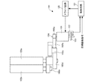
図4、図5は、本発明の一実施の形態に係る画像形成装置の原稿搬送装置のローラ駆動部の概略構成を示す図である。 4 and 5 are diagrams showing a schematic configuration of a roller driving unit of the document conveying device of the image forming apparatus according to the embodiment of the present invention.
図4、図5において、駆動装置151は、図3に示す原稿搬送装置150の何れかの駆動ローラを駆動するモータおよびその制御回路等からなるものである。
4 and 5, the driving
駆動装置151において、駆動源であるモータ101は、インナーロータ型DCブラシレスモータとして構成されており、出力軸124に固定されたギヤ102a、減速ギヤ102b、102c、102d、102e、102fを介し、ローラ104を回転させるようになっている。このローラ104は、例えば、図3における原稿搬送装置150の読取入口ローラ56、読取出口ローラ63、またはCIS出口ローラ67である。なお、ローラ104は、例えば、図1における画像形成装置100本体の給紙ローラ27等であってもよい。
In the
また、エンコーダディスク123は、周方向に所定の角度間隔で所定数のスリットを有し、出力軸124に対して垂直かつ同心にて固定され、出力軸124の回転とともに回転するようになっている。
The
光学センサであるフォトセンサ122は、エンコーダディスク123を挟み込む状態でモータ101に取り付けられ、エンコーダディスク123のスリットにより光路の伝達・遮断がなされ、パルス信号を制御回路121へと伝達するようになっている。
The
制御回路121では、フォトセンサ122からのパルス信号を計測することで、モータ101の回転量および回転速度を導出し、ローラ104の位置および速度情報から、用紙99の位置および速度情報を得ることが可能となる。
The
なお、フォトセンサ122は、2組の発光素子と受光素子を有し、各々のパルス信号の位相差が所定量(本実施の形態ではπ/2[rad])となるように配置されている。
Note that the
制御回路121は、図示しない目標駆動信号生成装置およびフォトセンサ122からの信号に基づいて、モータ101の動作信号を生成し、ドライバ回路125に動作信号を送り、その後、ドライバ回路125から動作信号に合った電流をモータ101に流すことで、ローラ104を駆動させる。
The
図6は、本発明の一実施の形態に係る画像形成装置の原稿搬送装置の駆動装置の概略構成を示す図である。 FIG. 6 is a diagram showing a schematic configuration of a driving device of the document conveying device of the image forming apparatus according to the embodiment of the present invention.
図6において、駆動装置151は、図3に示す原稿搬送装置150の何れかの駆動ローラを駆動するモータおよびその制御回路等からなるものである。
In FIG. 6, a
駆動装置151において、ローラ対103a、103bに挟まれながら用紙99(図3参照)が搬送されていく。このローラ対103a、103bは、例えば、図3における原稿搬送装置150の読取入口ローラ56、読取出口ローラ63、またはCIS出口ローラ67である。なお、ローラ104は、例えば、図1における画像形成装置100本体の給紙ローラ27等であってもよい。
In the
モータ101は、出力軸124に固定されたギヤ102a、減速ギヤ102b、102c、102d、102eを介し、ローラ対103a、103bを回転させる。
The
また、エンコーダディスク123は、周方向に所定の角度間隔で所定数のスリットを有し、出力軸124に垂直かつ同心にて固定され、出力軸124の回転とともに回転する。
The
光学センサであるフォトセンサ122は、エンコーダディスク123を挟み込む形でモータ101に取り付けられ、エンコーダディスク123のスリットにより光路の伝達・遮断がなされ、フォトセンサ122の受光素子にてパルス信号となって制御回路121へと伝達する。
A
制御回路121では、このパルス信号を計測することで、モータ101の回転量および回転速度を導出し、ローラ対103a、103bの位置および速度情報から、用紙99の位置および速度情報を得ることが可能となる。
By measuring this pulse signal, the
なお、フォトセンサ122は、2組の発光素子と受光素子を有し、各々のパルス信号位相差が所定量(本実施の形態ではπ/2[rad])となるように配置されている。
Note that the
制御回路121は、図示しない目標駆動信号生成装置およびフォトセンサ122からの信号に基づいて、モータ101の動作信号を生成し、ドライバ回路125に動作信号を送り、その後、ドライバ回路125から動作信号に合った電流をモータ101に流すことで、ローラ対103a、103bを駆動させる。
The
図7は、本発明の一実施の形態に係る画像形成装置の原稿搬送装置の駆動装置の概略構成を示す図である。 FIG. 7 is a diagram showing a schematic configuration of the driving device of the document conveying device of the image forming apparatus according to the embodiment of the present invention.
図7において、駆動装置151は、図3に示す原稿搬送装置150の何れかの駆動ローラを駆動するモータおよびその制御回路等からなるものである。
In FIG. 7, a
駆動装置151において、ローラ対103a、103bに挟まれながら用紙99(図3参照)が搬送されていく。このローラ対103a、103bは、例えば、図3における原稿搬送装置150の読取入口ローラ56、読取出口ローラ63、またはCIS出口ローラ67である。なお、ローラ104は、例えば、図1における画像形成装置100本体の給紙ローラ27等であってもよい。
In the
モータ101は、出力軸124に固定されたギヤ102a、減速ギヤ102b、102c、102d、102eを介し、ローラ対103a、103bを回転させる。
The
また、エンコーダディスク123は周方向に所定の角度間隔で所定数のスリットを有し、出力軸124とカップリング126を介してモータ101の軸に対して垂直かつ同心にて固定され、出力軸124の回転とともに回転する。
The
光学センサであるフォトセンサ122は、エンコーダディスク123を挟み込む形で図示しない固定部材に取り付けられ、エンコーダディスク123のスリットの無い箇所にて光の反射がおき、フォトセンサ122の受光素子にて光を検知する、この検知の有無でパルス信号を生成し、このパルス信号を制御回路121へと伝達する。
The
制御回路121では、このパルス信号を計測することで、モータ101の回転量および回転速度を導出し、ローラ対103a、103bの位置および速度情報から、用紙99の位置および速度情報を得ることが可能となる。
By measuring this pulse signal, the
なお、フォトセンサ122は、2組の発光素子と受光素子を有し、各々のパルス信号位相差が所定量(本実施の形態ではπ/2[rad])となるように配置されている。
Note that the
制御回路121は、図示しない目標駆動信号生成装置およびフォトセンサ122からの信号に基づいて、モータ101の動作信号を生成し、ドライバ回路125に動作信号を送り、その後、ドライバ回路125は、制御回路121からの動作信号に合った電流をモータ101に流すことで、ローラ対103a、103bを駆動させる。
The
図8は、本発明の一実施の形態に係る画像形成装置の駆動装置の構成を示す図である。 FIG. 8 is a diagram showing the configuration of the drive device of the image forming apparatus according to the embodiment of the present invention.
図8において、駆動装置151は、図1に示す画像形成装置100または図3に示す原稿搬送装置150の何れかの駆動ローラを駆動するモータおよびその制御回路等からなるものである。
In FIG. 8, a
駆動装置151において、外部の目標駆動信号生成手段130から、制御回路121内の目標位置・速度計算回路131に、回転方向信号と移動パルス数の信号が渡されるようになっている。すなわち、制御回路121内の目標位置・速度計算回路131は、外部の目標駆動信号生成手段130から、目標駆動信号としての回転方向信号と移動パルス数の信号を取得するようになっている。
In the
目標位置・速度計算回路131では、得られた情報と図示しないオシレータの時間情報から、目標位置および目標速度を導出し、位置・速度追従制御器133へと信号を伝達するようになっている。
The target position /
また、制御回路121内のモータ位置・速度計算回路132では、2チャンネルフォトセンサとして構成されたフォトセンサ122にて、エンコーダディスク123のパルスを計測している。フォトセンサ122およびエンコーダディスク123は、2チャンネルロータリエンコーダとして構成されている。
In addition, the motor position /
エンコーダディスク123の1周当りのパルス数は、本実施の形態では100パルスとしている。エンコーダディスク123の1周当りのパルス数は、安価にモータ101の出力軸124の回転を検出するために、200パルス以下であることが好ましい。
In the present embodiment, the number of pulses per revolution of the
また、エンコーダディスク123の1周当りのパルス数は、ステッピングモータからインナーロータ型DCブラシレスモータへの置き換えを容易にするために、12×Nパルス(Nは自然数)または50×Nパルスとすることが好ましい。
Also, the number of pulses per revolution of the
ここで、2チャンネルフォトセンサとして構成されたフォトセンサ122は、2組の発光素子と受光素子を有し、各々のパルス信号位相差が所定量(本実施の形態ではπ/2[rad])となるように配置されている。そのため、モータ位置・速度計算回路132ではその位相差を利用して、回転方向を知ることができる。
Here, the
モータ位置・速度計算回路132では、得られた情報と図示しないオシレータの時間情報から、モータ位置およびモータ速度を導出し、位置・速度追従制御器133へと信号を伝達するようになっている。
The motor position /
位置・速度追従制御器133では、目標位置とモータ位置が一致するよう、また目標速度とモータ速度が一致するよう制御し、必要に応じてPWM出力、回転方向、スタートストップ、ブレーキといった信号をドライバ回路125へと送るようになっている。
The position /
ドライバ回路125は、4象限ドライバとして構成されており、位置・速度追従制御器133から得られた信号およびホールIC135からのホール信号から、モータ電流およびPWM電圧を制御するようになっている。
The
すなわち、駆動装置151においては、制御回路121が、目標駆動信号から単位時間当りの目標回転量ΔXtおよび目標総回転量Xtを求めるとともに、フォトセンサ122、エンコーダディスク123からの出力信号から単位時間当りのモータ回転量ΔXmおよびモータ総回転量Xmを求め、その後、目標総回転量Xtとモータ総回転量Xmが等しく、且つ、単位時間当りの目標回転量ΔXtと単位時間当りのモータ回転量ΔXmが等しくなるようドライバ回路125への信号を変化させることで、モータ101の回転速度を制御するようになっている。
That is, in the
本実施の形態では、ドライバ回路125がモータ101に搭載されていない形式で示しているが、ドライバ回路125をモータ101上の基板に搭載した場合は、ハーネス本数の削減が図れるため、コストダウンにつながる。
In the present embodiment, the
なお、本実施の形態では、目標駆動信号生成手段130は、駆動装置151には含まれず、画像形成装置100の図示しない本体制御部や原稿搬送装置150の図示しないADF制御部等に設けられているが、目標駆動信号生成手段130が駆動装置151内に含まれていてもよい。
In the present embodiment, the target drive
図9(a)、図9(b)は、本発明の一実施の形態に係る画像形成装置のモータの構成を示す斜視図である。 FIG. 9A and FIG. 9B are perspective views showing the configuration of the motor of the image forming apparatus according to the embodiment of the present invention.
図9(a)、図9(b)に示すように、モータ101の出力軸124にギヤ102aを直接歯切りすることで、モータ初段の減速比を大きくすることができ、コストダウンも実現できるようになっている。
As shown in FIGS. 9A and 9B, the
また、出力軸124の駆動伝達部であるギヤ102aと逆側の端部には、エンコーダディスク123が同軸上に固定されている。また、フォトセンサ122は、モータ101に取り付けられ、ドライバ回路125(図8参照)もモータ101上の基板に取り付けられている。モータ101上の基板には、コネクタ127が取り付けられており、モータ信号とエンコーダ信号の入出力がなされるようになっている。
An
また、モータ101の軸受け部には、玉軸受けが用いられており、これにより、焼結軸受け等を用いた場合と比較して摩擦力が低減するので、DCモータであるモータ101を用いることによる高効率化を更に高められるとともに、高耐久化を図ることができるようになっている。
In addition, since a ball bearing is used for the bearing portion of the
図10(a)、図10(b)は、本発明の一実施の形態に係る画像形成装置のエンコーダディスクの構成を示す斜視図である。 FIGS. 10A and 10B are perspective views showing the configuration of the encoder disk of the image forming apparatus according to the embodiment of the present invention.
図10(a)は、エンコーダディスク123を溝穴タイプとしたものである。図10(a)において、エンコーダディスク123は、金属板にエッチング加工等により周方向(回転方向)に等間隔にスリット形状の穴123aを開けたものから構成されており、このようにエンコーダディスク123がスリット形状を有することにより、このスリット形状の穴の有無により、フォトセンサ122の受光素子が信号の有無を検知し、パルス検知をするようになっている。
FIG. 10A shows the
図10(b)は、エンコーダディスク123をフォトエッチングタイプとしたものである。図10(b)において、エンコーダディスク123は、フィルム上に黒インクでスリット123bを印刷したものから構成されており、この黒インクの有無により、フォトセンサ122の受光素子が信号の有無または光量の差異を検知し、パルス検知をするようになっている。図10(b)に示すエンコーダディスク123では、黒インクを用いているが、光量の差異(有無を含む)が検知できれば、黒インクでなくても構わない。
FIG. 10B shows the
なお、本実施の形態において、原稿搬送装置150は、画像形成装置100の一部として位置付けて取り扱っており、駆動装置151は、画像形成装置100の駆動ローラや画像形成装置100の一部としての原稿搬送装置150の駆動ローラを駆動するものとして説明しているが、原稿搬送装置150を画像形成装置100の周辺装置として位置付ける場合は、駆動装置151は、画像形成装置100の駆動ローラや画像形成装置100の周辺装置としての原稿搬送装置150の駆動ローラを駆動することとなる。
In the present embodiment, the
図11(a)、図11(b)、図12は、変形例として、アウターロータ型ブラシレスモータにエンコーダを取付けた構成を示している。図11(a)、図11(b)にその前面および背面をそれぞれ示すように、アウターロータ型ブラシレスモータをモータ101として用いるとともに、透過型センサをフォトセンサ122として用いて、このフォトセンサ122によってモータ101のアウターロータに一体的に形成した穴123aを検知する構成としたり、図12に示すように、アウターロータ型ブラシレスモータをモータ101として用いるとともに、反射型センサをフォトセンサ122として用いて、このフォトセンサ122によってモータ101のアウターロータに一体的に形成したスリット123bを検知する構成としてもよい。なお、図11(a)、図11(b)、図12のようにモータ101のアウターロータに直接的に穴123aやスリット123b等のスケールを形成する他に、図10(a)、図10(b)に示すエンコーダディスク123をモータ101に取り付け、エンコーダディスク123をフォトセンサ122で読取るように構成してもよい。
FIG. 11A, FIG. 11B, and FIG. 12 show a configuration in which an encoder is attached to an outer rotor type brushless motor as a modification. As shown in FIG. 11A and FIG. 11B, the front and back surfaces of the outer rotor type brushless motor are used as the
本実施の形態では、図4〜図9に示すインナーロータ型DCブラシレスモータとして構成されたモータ101、または図11(a)、図11(b)、図12に示すアウターロータ型ブラシレスモータとして構成されたモータ101の回転量と回転方向を検知し、制御回路121によりこのモータ101の回転速度または回転位置の少なくとも一方を制御するようになっている。
In the present embodiment, the
以上のように、本実施の形態に係る駆動装置151は、駆動源としてのインナーロータ型DCブラシレスモータであるモータ101と、モータ101の出力軸124の回転量と回転方向を検知するフォトセンサ122、エンコーダディスク123と、モータ101の回転を制御する制御回路121と、制御回路121からの信号に基づいてモータ101に駆動電力を供給するドライバ回路125と、を備える駆動装置151において、制御回路121が、外部から取得したモータ101の目標駆動信号と、フォトセンサ122、エンコーダディスク123から検出される検出信号とに基づいて、ドライバ回路125への信号(動作信号)を変化させることで、モータ101の回転速度または回転位置の少なくとも一方を制御することを特徴とする。
As described above, the driving
この構成により、モータ101としてインナーロータ型DCブラシレスモータを用いることにより、ステッピングモータを用いる場合よりエネルギー効率を高く、モータ重量を削減することができるとともに、アウターロータ型と比較してイナーシャが小さくなることから、ステッピングモータと同等の加減速時間にすることができ、また、ブラシ付モータと比較して、ブラシ磨耗が無いので高耐久にすることができる。
With this configuration, by using an inner rotor type DC brushless motor as the
また、仮にフォトセンサ122やエンコーダディスク123等の回転検出手段がモータ101の出力軸124の回転ではなく被駆動体(ローラ104等)の回転を検知するように構成した場合には、モータ1回転当りの被駆動体の移動量等を考慮した制御設計をしなければならないという不都合や、伝達系や被駆動体の構成が変わったり別の箇所に同じ駆動装置を適用する場合に制御手段の設計を変えなければならないという不都合が生じるが、フォトセンサ122やエンコーダディスク123でモータ101の出力軸124の回転量と回転方向を検知する構成とすることにより、これらの不都合を回避でき、設計を容易にすることができる。
Further, if the rotation detection means such as the
したがって、高効率であるとともにステッピングモータと同等の加減速時の追従性やモータ101の耐久性を得ることができる。
Accordingly, it is possible to obtain high efficiency and followability during acceleration / deceleration equivalent to that of a stepping motor and durability of the
また、本実施の形態に係る駆動装置151は、制御回路121が、目標駆動信号から単位時間当りの目標回転量ΔXtおよび目標総回転量Xtを求めるとともに、フォトセンサ122、エンコーダディスク123からの出力信号から単位時間当りのモータ回転量ΔXmおよびモータ総回転量Xmを求め、その後、目標総回転量Xtとモータ総回転量Xmが等しく、且つ、単位時間当りの目標回転量ΔXtと単位時間当りのモータ回転量ΔXmが等しくなるようドライバ回路125への信号を変化させることで、モータ101の回転速度を制御することを特徴とする。
In the
この構成により、目標駆動信号とフォトセンサ122、エンコーダディスク123からの出力信号から、位置・速度情報を取得し、差分によってドライバ回路125への信号を変化することで、モータ101の位置・速度・Hold制御を行うことができる。
With this configuration, position / velocity information is acquired from the target drive signal and the output signal from the
また、本実施の形態に係る駆動装置151は、ドライバ回路125として4象限ドライバを用いることを特徴とする。
Further, the driving
この構成により、4象限ドライバを用いない場合は、回生電流を流すことができず、機械的な負荷等により自然に止まるのを待つしかなく、無制御状態になってしまうが、4象限ドライバを用いることにより、回生電流を流して停止させること、すなわち、制御しながらの停止を行うことができるので、モータ101をステッピングモータと同様に用いることができる。
With this configuration, when a four-quadrant driver is not used, a regenerative current cannot be passed, and there is no choice but to wait for it to stop naturally due to a mechanical load or the like. By using it, the regenerative current can be applied to stop, that is, the control can be stopped while being controlled, so that the
また、本実施の形態に係る駆動装置151は、回転検出手段としてエンコーダディスク123を有する2チャンネルロータリエンコーダを用い、エンコーダディスク123の1周当りのパルス数が200パルス以下であることを特徴とする。
Further, the driving
この構成により、2チャンネルロータリエンコーダを用いることで、回転方向を判別することができ、また、1周200パルス以下のエンコーダディスク123を用いることで、安価にモータ101の出力軸124の回転を検出することができる。
With this configuration, the rotation direction can be determined by using a two-channel rotary encoder, and the rotation of the
また、本実施の形態に係る駆動装置151は、エンコーダディスク123の1周当りのパルス数が、12×Nパルス(Nは自然数)または50×Nパルスであることを特徴とする。
Further, the
この構成により、一般に、PMモータは2相励磁にて1周48パルス、HBモータは2相励磁にて1周200パルスとなっているが、エンコーダにて検出される値あるいはその2逓倍・4逓倍の値を用いることで、モータ101の1回転当りの検出パルス数を、ステッピングモータの1回転当りのパルス数に合わせ、ステッピングモータからインナーロータ型DCブラシレスモータであるモータ101への置換え時に目標駆動信号生成手段130の出力信号を変えずに、そのまま制御回路121への目標駆動信号に使用することができる。
With this configuration, PM motors generally have 48 pulses per revolution with two-phase excitation, and HB motors have 200 pulses per revolution with two-phase excitation. By using the multiplication value, the number of detected pulses per one rotation of the
また、本実施の形態に係る駆動装置151は、回転検出手段であるエンコーダディスク123を、モータ101の出力軸124の駆動伝達部とは逆側の端部に固定したことを特徴とする。
Further, the
この構成により、エンコーダディスク123を、モータ101の出力軸124の駆動伝達部とは逆側の端部に固定したことにより、エンコーダディスク123が出力軸124と一体構成となり、ハーネス経路を簡略化でき、設置スペースを小さく、また、エンコーダディスク123の取付精度の向上による1回転偏芯成分を少なくすることができる。
With this configuration, the
また、本実施の形態に係る駆動装置151は、エンコーダディスク123が金属製であることを特徴とする。
In addition, the driving
この構成により、エンコーダディスク123を金属製とすることにより、プラスチックやフィルム等を用いる場合と比較し、モータ101等の熱源による発熱の影響を抑えることができる。
With this configuration, the
また、本実施の形態に係る駆動装置151は、エンコーダディスク123はスリット形状を有し、フォトセンサ122は、スリット形状の有無を検知することで、移動量を検出することを特徴とする。
The
この構成により、スリット形状を設けずに反射率の違いにより検知する場合や、透過率の違いにより検出する場合と比較し、エンコーダディスク123へのゴミの付着等による誤検知を減らすことができる。
With this configuration, it is possible to reduce false detection due to dust adhering to the
また、本実施の形態に係る駆動装置151は、モータ101の軸受け部に、玉軸受けを用いることを特徴とする。
Further, the driving
この構成により、玉軸受けを用いることにより、焼結軸受け等を用いた場合と比較して摩擦力が低減するので、DCモータであるモータ101を用いることによる高効率化を更に高められるとともに、高耐久化を図ることができる。
With this configuration, by using a ball bearing, the frictional force is reduced as compared with the case where a sintered bearing or the like is used. Therefore, high efficiency can be further improved by using the
また、本実施の形態に係る駆動装置151は、モータ101に、ホールIC135を用いることを特徴とする。
Further, the driving
この構成により、ホール素子は、一般にホール信号が低電圧のアナログ信号で出力されるためノイズに弱いという性質があり、ドライバ回路125がモータ101の近傍に配置されている場合はノイズの影響を受けにくいが、ドライバ回路125がモータ101から離れた場所にある場合にその経路の途中でノイズを拾ってしまって誤検知する可能性が高くなるが、ホールIC135を用いることにより、High・Lowのデジタル信号で出力されるため、ノイズに強くすることができる。
With this configuration, the Hall element is generally susceptible to noise because the Hall signal is output as a low-voltage analog signal. When the
また、本実施の形態に係る駆動装置151は、モータ101の出力軸124にギヤ102aの歯を直接設けることを特徴とする。
Further, the
この構成により、インナーロータ型DCブラシレスモータであるモータ101は、ステッピングモータと比較して高回転域で高効率となる特性があり、ステッピングモータより高回転で用いることが多いが、被駆動体までの減速比を多くするのに、出力軸124に圧入する等してギヤを設ける場合と比較して、1周の歯数を少なくすることにより減速比を多くすることができる。また、モータ101の出力軸124とは別にギヤを設ける場合と比較して、コストダウン・重量ダウンを図ることができる。
With this configuration, the
また、本実施の形態に係る画像形成装置100は、上記の駆動装置151を備えることを特徴とする。
Further, the
この構成により、駆動装置151を備える画像形成装置100において、高効率であるとともにステッピングモータと同等の加減速時の追従性やモータ101の耐久性を得ることができる。
With this configuration, in the
また、本実施の形態に係る原稿搬送装置150は、上記の駆動装置151を備えることを特徴とする。
Further, the
この構成により、駆動装置151を備える原稿搬送装置150において、高効率であるとともにステッピングモータと同等の加減速時の追従性やモータ101の耐久性を得ることができる。
With this configuration, in the
図13は、本発明の一実施の形態に係る画像形成装置の駆動装置の他の例を示す図である。 FIG. 13 is a diagram illustrating another example of the driving device of the image forming apparatus according to the embodiment of the present invention.
図13において、駆動装置151は、図8で示す構成においてモータ101にモータFG136を設けるとともに制御回路121にPLL制御器137を設けた構成とすることにより、モータ101の回転条件によってFG信号に基づくPLL制御に切り替えることで回転安定度を高めるようにしたものである。なお、図8と同様の構成部材には同一の符号を付して説明を省略する。
In FIG. 13, the driving
制御回路121内のPLL制御器137では、モータ101に設けたモータFG(周波数ジェネレータ)136から出力されるFG信号から得られた情報と、図示しないオシレータの時間情報からモータ速度を導出し、目標速度とモータ速度が一致するよう制御し、必要に応じてPWM出力、回転方向、スタートストップ、ブレーキといった信号をドライバ回路125へと送るようになっている。
The
図13の構成では、モータ101を制御方法として、モータFG136からのFG信号に基づいた制御も行うようになっている。このため、モータの回転安定度を高くすることが可能となる。
In the configuration of FIG. 13, control based on the FG signal from the
また、制御回路121は、モータFG136から検出される検出信号に基づいてモータ101の回転速度を制御するときには、PLL制御を行うようになっている。このため、定常時(モータ101を速度変更することなく一定速度で回転させるとき)にPLL制御とすることで、回転安定度を高くすることが可能となる。
The
また、制御回路121は、目標駆動信号から求められる目標速度変更時においては、フォトセンサ122とエンコーダディスク123から検出される検出信号に基づいてモータ101の回転速度を制御するとともに、一定速度回転時においては、モータFG136から検出される検出信号に基づいてモータ101の回転速度を制御するようになっている。
Further, the
このため、定常時にFG信号を用いることで速度安定性が特に求められる一定速度回転時に速度安定度を高くできる。また、速度変動時にはPI制御、PID制御などのFB制御を用いることで、加速時の立ち上げをなだらかにすることができる。これにより、PLL制御での立ち上げのように、急加速する場合と比較し、加速時、特に停止からの立ち上げ時におけるギヤへの衝撃負荷を低減することができ、ギヤ寿命を向上することが可能となる。 For this reason, by using the FG signal in the steady state, the speed stability can be increased during the constant speed rotation in which speed stability is particularly required. In addition, when the speed varies, FB control such as PI control and PID control can be used to smoothly start up the vehicle during acceleration. This makes it possible to reduce the impact load on the gear at the time of acceleration, especially at the time of start-up from a stop, and improve the life of the gear, compared with the case of sudden acceleration as in the case of start-up by PLL control. Is possible.
また、制御回路121は、モータ101が500rpm以下の一定速度回転時であるときは、フォトセンサ122とエンコーダディスク123から検出される検出信号に基づいて、モータ101の回転速度を制御するようになっている。このため、定常時にPLL制御とすることで、回転安定度を高くすることが可能となる。
Further, when the
また、フォトセンサ122とエンコーダディスク123が検知する1周当りの分解能をN1、モータFG136が検知する1周当りの分解能をN2、とすると、N1≧N2となっている。このため、モータFG136が検知する1周当りの分解能(N2)を小さくすることができるため、コストダウンが可能となる。
Further, assuming that the resolution per rotation detected by the
また、フォトセンサ122とエンコーダディスク123が検知する1周当りの分解能をN1、モータFG136が検知する1周当りの分解能をN2、Aを自然数、とすると、N1=A・N2となっている。このため、N1=A・N2とすることで、制御回路121における変換が容易となり、制御プログラムの簡素化が可能となる。特に、N1=N2(A=1)の場合は変換を不要とすることができる。
Further, assuming that the resolution per rotation detected by the
以上のように、本実施の形態に係る駆動装置151は、モータ101のFG信号を取得するモータFG136を更に備え、制御回路121が、外部から取得した目標駆動信号と、フォトセンサ122とエンコーダディスク123から検出される検出信号またはモータFG136から検出される検出信号の何れかに基づいて、ドライバ回路125への信号を変化させることで、モータ101の回転速度または回転位置の少なくとも一方を制御することを特徴とする。なお、本実施の形態におけるフォトセンサ122およびエンコーダディスク123は、本発明における回転検出手段を構成する。
As described above, the
この構成により、FG信号を用いることでモータ101の回転安定度を高くすることが可能となる。
With this configuration, it is possible to increase the rotational stability of the
また、本実施の形態に係る駆動装置151は、制御回路121が、モータFG136から検出される検出信号に基づいてモータ101の回転速度を制御するときには、PLL制御器137を用いたPLL制御を行うことを特徴とする。
In addition, the
この構成により、定常時にPLL制御とすることで、回転安定度を高くすることが可能となる。 With this configuration, it is possible to increase the rotational stability by performing PLL control in a steady state.
また、本実施の形態に係る駆動装置151は、制御回路121が、目標駆動信号から求められる目標速度変更時においては、フォトセンサ122とエンコーダディスク123から検出される検出信号に基づいて、モータ101の回転速度を制御するとともに、一定速度回転時においては、モータFG136から検出される検出信号に基づいて、モータ101の回転速度を制御することを特徴とする。
Further, in the
この構成により、定常時にFG信号を用いることで、速度安定性が特に求められる一定速度回転時に速度安定度を高くすることができる。また、速度変動時にはPI制御PID制御などのFB制御を用いることで、加速時の立ち上げをなだらかにすることができる。これにより、PLL制御での立ち上げのように、急加速する場合と比較し、加速時、特に停止からの立ち上げ時におけるギヤへの衝撃負荷を低減することができ、ギヤ寿命を向上することが可能となる。 With this configuration, by using the FG signal in a steady state, the speed stability can be increased during constant speed rotation where speed stability is particularly required. Further, when the speed fluctuates, by using FB control such as PI control PID control, the startup at the time of acceleration can be made smooth. This makes it possible to reduce the impact load on the gear at the time of acceleration, especially at the time of start-up from a stop, and improve the life of the gear, compared with the case of sudden acceleration as in the case of start-up by PLL control. Is possible.
また、本実施の形態に係る駆動装置151は、制御回路121が、モータ101が500rpm以下の一定速度回転時であるときは、フォトセンサ122とエンコーダディスク123から検出される検出信号に基づいて、モータ101の回転速度を制御することを特徴とする。
Further, in the
この構成により、定常時にPLL制御とすることで、回転安定度を高くすることが可能となる。 With this configuration, it is possible to increase the rotational stability by performing PLL control in a steady state.
また、本実施の形態に係る駆動装置151は、フォトセンサ122とエンコーダディスク123が検知する1周当りの分解能をN1、モータFG136が検知する1周当りの分解能をN2、とすると、N1≧N2であることを特徴とする。
Further, in the
この構成により、モータFG136が検知する1周当りの分解能(N2)を小さくすることができるため、コストダウンが可能となる。 With this configuration, it is possible to reduce the resolution per revolution (N2) detected by the motor FG136, so that the cost can be reduced.
また、本実施の形態に係る駆動装置151は、フォトセンサ122とエンコーダディスク123が検知する1周当りの分解能をN1、モータFG136が検知する1周当りの分解能をN2、Aを自然数、とすると、N1=A・N2であることを特徴とする。
Further, the driving
この構成により、N1=A・N2とすることで、制御回路121における変換が容易となり、制御プログラムの簡素化が可能となる。特に、N1=N2(A=1)の場合は変換を不要とすることができる。
With this configuration, by setting N1 = A · N2, conversion in the
以上説明したように、本発明に係る駆動装置および画像形成装置は、高効率であるとともにステッピングモータと同等の加減速時の追従性やモータの耐久性を得ることができるという効果を有し、複写機、ファクシミリ、プリンタ等の画像形成装置、画像形成装置の駆動装置および画像形成装置の周辺装置として有用である。 As described above, the drive device and the image forming apparatus according to the present invention have an effect of being able to obtain high efficiency and followability at the time of acceleration / deceleration equivalent to that of a stepping motor and motor durability. It is useful as an image forming apparatus such as a copying machine, a facsimile machine, and a printer, a driving device for the image forming apparatus, and a peripheral device for the image forming apparatus.
100 画像形成装置
101 モータ
102a ギヤ
102b、102c、102d、102e、102f 減速ギヤ
103a、103b ローラ対
104 ローラ
121 制御回路(制御手段)
122 フォトセンサ
123 エンコーダディスク
123a 穴
123b スリット
124 出力軸
125 ドライバ回路(ドライバ)
126 カップリング
127 コネクタ
130 目標駆動信号生成手段
131 目標位置・速度計算回路
132 モータ位置・速度計算回路
133 位置・速度追従制御器
135 ホールIC
136 モータFG(FG信号検出手段)
137 PLL制御器
150 原稿搬送装置(画像形成装置の周辺装置)
151 駆動装置
DESCRIPTION OF
122
126
136 Motor FG (FG signal detecting means)
137
151 Drive device
Claims (13)
前記インナーロータ型DCブラシレスモータの回転軸と同軸に取り付けられたエンコーダディスクと、
前記エンコーダディスクの回転に応じてエンコーダ信号を出力するセンサと、
前記駆動装置の外部の制御手段から出力される駆動信号に基づいて前記インナーロータ型DCブラシレスモータに電流を供給するドライバ回路と、
前記基板に設けられた入出力部と、を備え、
前記エンコーダ信号は前記入出力部を介して前記制御手段へ出力され、
前記制御手段の外部から入力された信号と前記エンコーダ信号とに基づいて前記制御手段から出力された前記駆動信号は、前記入出力部を介してドライバ回路へ入力されることを特徴とする駆動装置。 A driving device comprising: an inner rotor type DC brushless motor for driving a load; and a substrate provided on the opposite side of the load with respect to the inner rotor type DC brushless motor,
An encoder disk mounted coaxially with the rotating shaft of the inner rotor type DC brushless motor;
A sensor that outputs an encoder signal according to the rotation of the encoder disk;
A driver circuit for supplying a current to the inner rotor type DC brushless motor based on a driving signal output from a control means external to the driving device;
An input / output unit provided on the substrate,
The encoder signal is output to the control means via the input / output unit,
The driving signal output from the control means on the basis of the outside from the input signal and the encoder signal and said control means, driving apparatus characterized by being inputted to the driver circuit through the input-output unit .
前記エンコーダ信号と外部から入力された信号とに基づいて前記駆動信号を出力する、前記駆動装置外部の制御手段と、
を有するモータシステム。 The drive device according to any one of claims 1 to 9,
Control means external to the drive device for outputting the drive signal based on the encoder signal and an externally input signal ;
A motor system.
Priority Applications (1)
| Application Number | Priority Date | Filing Date | Title |
|---|---|---|---|
| JP2011097262A JP5899648B2 (en) | 2010-07-27 | 2011-04-25 | Drive device, image forming apparatus, and peripheral device of image forming apparatus |
Applications Claiming Priority (5)
| Application Number | Priority Date | Filing Date | Title |
|---|---|---|---|
| JP2010168368 | 2010-07-27 | ||
| JP2010168368 | 2010-07-27 | ||
| JP2011060078 | 2011-03-18 | ||
| JP2011060078 | 2011-03-18 | ||
| JP2011097262A JP5899648B2 (en) | 2010-07-27 | 2011-04-25 | Drive device, image forming apparatus, and peripheral device of image forming apparatus |
Related Child Applications (1)
| Application Number | Title | Priority Date | Filing Date |
|---|---|---|---|
| JP2016043046A Division JP6354775B2 (en) | 2010-07-27 | 2016-03-07 | Drive device, image forming apparatus, and peripheral device of image forming apparatus |
Publications (3)
| Publication Number | Publication Date |
|---|---|
| JP2012213308A JP2012213308A (en) | 2012-11-01 |
| JP2012213308A5 JP2012213308A5 (en) | 2014-11-06 |
| JP5899648B2 true JP5899648B2 (en) | 2016-04-06 |
Family
ID=44857718
Family Applications (6)
| Application Number | Title | Priority Date | Filing Date |
|---|---|---|---|
| JP2011097262A Ceased JP5899648B2 (en) | 2010-07-27 | 2011-04-25 | Drive device, image forming apparatus, and peripheral device of image forming apparatus |
| JP2016043046A Active JP6354775B2 (en) | 2010-07-27 | 2016-03-07 | Drive device, image forming apparatus, and peripheral device of image forming apparatus |
| JP2017218369A Active JP6551493B2 (en) | 2010-07-27 | 2017-11-13 | Drive device, image forming apparatus, and peripheral device of image forming apparatus |
| JP2018210379A Active JP6888599B2 (en) | 2010-07-27 | 2018-11-08 | Drive device, image forming device and peripheral device of image forming device |
| JP2018210382A Active JP6888600B2 (en) | 2010-07-27 | 2018-11-08 | Drive device, image forming device and peripheral device of image forming device |
| JP2019125215A Active JP6888647B2 (en) | 2010-07-27 | 2019-07-04 | Drive device, image forming device and peripheral device of image forming device |
Family Applications After (5)
| Application Number | Title | Priority Date | Filing Date |
|---|---|---|---|
| JP2016043046A Active JP6354775B2 (en) | 2010-07-27 | 2016-03-07 | Drive device, image forming apparatus, and peripheral device of image forming apparatus |
| JP2017218369A Active JP6551493B2 (en) | 2010-07-27 | 2017-11-13 | Drive device, image forming apparatus, and peripheral device of image forming apparatus |
| JP2018210379A Active JP6888599B2 (en) | 2010-07-27 | 2018-11-08 | Drive device, image forming device and peripheral device of image forming device |
| JP2018210382A Active JP6888600B2 (en) | 2010-07-27 | 2018-11-08 | Drive device, image forming device and peripheral device of image forming device |
| JP2019125215A Active JP6888647B2 (en) | 2010-07-27 | 2019-07-04 | Drive device, image forming device and peripheral device of image forming device |
Country Status (2)
| Country | Link |
|---|---|
| US (2) | US8796962B2 (en) |
| JP (6) | JP5899648B2 (en) |
Families Citing this family (17)
| Publication number | Priority date | Publication date | Assignee | Title |
|---|---|---|---|---|
| US8928270B2 (en) | 2011-09-26 | 2015-01-06 | Ricoh Company, Ltd. | Electric motor system and motor control method |
| JP2013219871A (en) * | 2012-04-05 | 2013-10-24 | Canon Inc | Motor control device |
| JP5729361B2 (en) | 2012-08-08 | 2015-06-03 | 株式会社リコー | Motor control device, drive device, conveyance device, image processing device, motor control method, and motor control program |
| JP6123477B2 (en) * | 2013-03-14 | 2017-05-10 | 株式会社リコー | Conveying device, control method and control program for conveying device |
| JP6252239B2 (en) | 2013-05-13 | 2017-12-27 | 株式会社リコー | Paper processing apparatus and image forming system |
| JP2015019563A (en) | 2013-06-10 | 2015-01-29 | 株式会社リコー | Control device, drive device, and image forming apparatus |
| WO2016104378A1 (en) | 2014-12-22 | 2016-06-30 | 日本電産株式会社 | Position estimation method and position control device |
| US20170187321A1 (en) * | 2015-12-28 | 2017-06-29 | Ricoh Company, Ltd. | Motor control device, motor control system, image forming apparatus, conveyance apparatus, and motor control method |
| JP6604221B2 (en) * | 2016-02-03 | 2019-11-13 | コニカミノルタ株式会社 | Driving device, fixing device and image forming apparatus |
| DE102016106581A1 (en) * | 2016-04-11 | 2017-10-12 | Bühler Motor GmbH | electric motor |
| EP3296063B1 (en) | 2016-06-24 | 2020-03-25 | Black & Decker Inc. | Control scheme for power tool having a brushless motor |
| JP2018007532A (en) | 2016-07-08 | 2018-01-11 | 株式会社リコー | Motor control device, motor drive device, motor drive system, image formation device, and transport device |
| US10053317B2 (en) | 2016-08-08 | 2018-08-21 | Ricoh Company, Ltd. | Contact-and-separation system, image forming apparatus, and contact-and-separation method |
| US10637331B2 (en) * | 2016-10-28 | 2020-04-28 | UBTECH Robotics Corp. | Servo |
| JP6934394B2 (en) * | 2017-11-02 | 2021-09-15 | ローム株式会社 | DC motor drive circuit, drive method and electronic equipment using it |
| US20230155467A1 (en) * | 2020-04-08 | 2023-05-18 | Nidec Servo Corporation | Single-phase brushless dc motor |
| JP2022142651A (en) | 2021-03-16 | 2022-09-30 | 株式会社リコー | Electrical unit and image forming apparatus |
Family Cites Families (41)
| Publication number | Priority date | Publication date | Assignee | Title |
|---|---|---|---|---|
| JPS60176477A (en) | 1984-02-22 | 1985-09-10 | Nippon Electric Ind Co Ltd | Controller of dc motor |
| JPS627387A (en) * | 1985-06-28 | 1987-01-14 | Matsushita Electric Ind Co Ltd | Ac servo motor encoder |
| JPH0349685A (en) | 1989-07-18 | 1991-03-04 | Kirin Brewery Co Ltd | Novel dna chain and its use |
| US5130710A (en) * | 1989-10-18 | 1992-07-14 | Pitney Bowes Inc. | Microcomputer-controlled electronic postage meter having print wheels set by separate D.C. motors |
| JPH04213707A (en) * | 1990-12-12 | 1992-08-04 | Canon Inc | Angular positioning device |
| JPH04197091A (en) * | 1990-11-28 | 1992-07-16 | Fuji Xerox Co Ltd | Motor controller |
| JPH05252688A (en) * | 1992-03-04 | 1993-09-28 | Yokogawa Electric Corp | Intelligent motor |
| JPH0775369A (en) * | 1993-06-29 | 1995-03-17 | Yamamoto Denki Kk | Method and apparatus for controlling phase angle of brushless motor |
| US5912541C1 (en) * | 1994-11-30 | 2002-06-11 | Animatics Corp | Integrated servo motor and controller |
| JP3293435B2 (en) | 1995-11-20 | 2002-06-17 | セイコーエプソン株式会社 | Motor drive |
| JP3503429B2 (en) | 1997-07-08 | 2004-03-08 | 富士ゼロックス株式会社 | Motor control device |
| JP4128249B2 (en) * | 1997-10-06 | 2008-07-30 | オリエンタルモーター株式会社 | Control device for position control motor |
| JP2000116173A (en) * | 1998-10-06 | 2000-04-21 | Kokusan Denki Co Ltd | Brushless dc motor and its speed-control method |
| US6459225B1 (en) * | 1999-04-27 | 2002-10-01 | Canon Kabushiki Kaisha | Servo-control apparatus for motor |
| JP3570617B2 (en) * | 1999-09-06 | 2004-09-29 | セイコーエプソン株式会社 | DC motor control device and control method |
| JP2001119914A (en) * | 1999-10-15 | 2001-04-27 | Yamaha Motor Co Ltd | Detector for rotor position of motor |
| EP1124320B1 (en) * | 2000-02-09 | 2008-09-10 | Seiko Epson Corporation | Motor control method and motor control apparatus |
| JP2002010664A (en) | 2000-06-15 | 2002-01-11 | Ricoh Co Ltd | Rotation-control unit for dc motor |
| JP3542032B2 (en) | 2000-12-11 | 2004-07-14 | 株式会社ダイヘン | Servo control method and apparatus for DC motor |
| EP1408607A1 (en) * | 2001-07-06 | 2004-04-14 | Seiko Epson Corporation | Motor controller |
| JP4191437B2 (en) * | 2002-06-26 | 2008-12-03 | 並木精密宝石株式会社 | Board-integrated brushless motor |
| JP4213946B2 (en) * | 2002-08-19 | 2009-01-28 | 日本電産シンポ株式会社 | Electric wheeling device |
| JP4481137B2 (en) * | 2003-11-13 | 2010-06-16 | アスモ株式会社 | Motor, rotation control device, and rotation detection circuit |
| JP4685371B2 (en) * | 2004-05-18 | 2011-05-18 | セイコーエプソン株式会社 | Relative drive |
| JP2006067736A (en) | 2004-08-27 | 2006-03-09 | Asmo Co Ltd | Motor and its manufacturing method |
| JP2006292724A (en) * | 2005-03-17 | 2006-10-26 | Ricoh Co Ltd | Rotation angle detector, apparatus and method for manufacturing the detector, recording medium and image forming apparatus |
| US7633256B2 (en) * | 2005-05-04 | 2009-12-15 | Lexmark International, Inc. | Encoder eccentricity correction for motion control systems |
| JP2006349072A (en) * | 2005-06-16 | 2006-12-28 | Nidec Shibaura Corp | Geared motor |
| JP5039357B2 (en) * | 2006-02-14 | 2012-10-03 | 株式会社リコー | Brushless motor drive control apparatus, image reading apparatus, and image forming apparatus |
| JP2007282298A (en) * | 2006-04-03 | 2007-10-25 | Nissan Motor Co Ltd | Motor controller |
| JP4218730B2 (en) * | 2006-04-26 | 2009-02-04 | 双葉電子工業株式会社 | Servo device |
| JP5056069B2 (en) * | 2007-02-27 | 2012-10-24 | ブラザー工業株式会社 | Motor control method and motor control apparatus |
| JP2008222002A (en) * | 2007-03-12 | 2008-09-25 | Jtekt Corp | Electric power steering device |
| US8068766B2 (en) | 2007-07-12 | 2011-11-29 | Ricoh Company, Ltd. | Rotary drive device and image forming apparatus |
| JP5107011B2 (en) | 2007-12-12 | 2012-12-26 | 株式会社リコー | Drive control apparatus and image forming apparatus having the same |
| US8064802B2 (en) | 2007-12-28 | 2011-11-22 | Ricoh Company, Ltd. | Driving-force transmission device and image forming apparatus |
| JP5277992B2 (en) * | 2008-01-30 | 2013-08-28 | 株式会社リコー | Belt drive control device and image forming apparatus |
| JP5558670B2 (en) * | 2008-02-08 | 2014-07-23 | キヤノン株式会社 | MOTOR DRIVE CONTROL DEVICE, ITS CONTROL METHOD, AND IMAGING DEVICE |
| JP2009223177A (en) | 2008-03-18 | 2009-10-01 | Ricoh Co Ltd | Belt drive controller, belt device, and image forming device |
| JP5234412B2 (en) | 2008-04-08 | 2013-07-10 | 株式会社リコー | Belt drive device and image forming apparatus |
| JP5322501B2 (en) * | 2008-05-29 | 2013-10-23 | キヤノン株式会社 | Drive device and electronic device |
-
2011
- 2011-04-25 JP JP2011097262A patent/JP5899648B2/en not_active Ceased
- 2011-07-08 US US13/067,940 patent/US8796962B2/en active Active
-
2014
- 2014-07-01 US US14/321,237 patent/US9263978B2/en active Active
-
2016
- 2016-03-07 JP JP2016043046A patent/JP6354775B2/en active Active
-
2017
- 2017-11-13 JP JP2017218369A patent/JP6551493B2/en active Active
-
2018
- 2018-11-08 JP JP2018210379A patent/JP6888599B2/en active Active
- 2018-11-08 JP JP2018210382A patent/JP6888600B2/en active Active
-
2019
- 2019-07-04 JP JP2019125215A patent/JP6888647B2/en active Active
Also Published As
| Publication number | Publication date |
|---|---|
| JP2018057262A (en) | 2018-04-05 |
| JP2019054725A (en) | 2019-04-04 |
| JP6551493B2 (en) | 2019-07-31 |
| US20140312819A1 (en) | 2014-10-23 |
| US20110266990A1 (en) | 2011-11-03 |
| US9263978B2 (en) | 2016-02-16 |
| JP6888600B2 (en) | 2021-06-16 |
| JP6888647B2 (en) | 2021-06-16 |
| JP2019024316A (en) | 2019-02-14 |
| JP6888599B2 (en) | 2021-06-16 |
| US8796962B2 (en) | 2014-08-05 |
| JP2016123269A (en) | 2016-07-07 |
| JP2012213308A (en) | 2012-11-01 |
| JP2019165632A (en) | 2019-09-26 |
| JP6354775B2 (en) | 2018-07-11 |
Similar Documents
| Publication | Publication Date | Title |
|---|---|---|
| JP6551493B2 (en) | Drive device, image forming apparatus, and peripheral device of image forming apparatus | |
| US9187280B2 (en) | Sheet feeding device, control method for the sheet feeding device, and image forming apparatus incorporating the sheet feeding device | |
| JP5729361B2 (en) | Motor control device, drive device, conveyance device, image processing device, motor control method, and motor control program | |
| JP5742025B2 (en) | DC motor with driver board, motor system, conveyance device, and image forming apparatus | |
| JP6028321B2 (en) | Driving device and image forming apparatus having the same | |
| JP5867811B2 (en) | Sheet conveying apparatus and image forming apparatus | |
| JP5896273B2 (en) | Motor driving device, sheet conveying device, and image forming apparatus | |
| JP2014030922A (en) | Driving device and image forming apparatus including the same | |
| JP5142855B2 (en) | Image forming apparatus | |
| JP6390341B2 (en) | Sheet conveying apparatus, image forming apparatus, sheet characteristic estimating method, and sheet characteristic estimating program | |
| JP6071032B2 (en) | Motor driving device, motor driving system, sheet conveying device, and image forming apparatus | |
| JP2015146728A (en) | Motor drive device, sheet transport device, and image forming device | |
| JP2011059460A (en) | Medium conveying device and image forming apparatus | |
| JP2012105466A (en) | Driving device and image formation device | |
| JP6281355B2 (en) | Paper feeding device and image forming apparatus | |
| JP2017218313A (en) | Sheet conveyance device, image formation apparatus and sheet conveyance method | |
| JP4484207B2 (en) | Image forming apparatus | |
| JP6657840B2 (en) | Sheet conveying device, image forming device, sheet characteristic estimating method | |
| JP6175747B2 (en) | Driving device and image forming apparatus | |
| JP2007078997A (en) | Image forming apparatus | |
| JP2002108168A (en) | Image forming device | |
| JP2016175744A (en) | Sheet conveyance device, image formation device, sheet conveyance method and sheet conveyance program | |
| JP2010122571A (en) | Conveying device, image forming device and program |
Legal Events
| Date | Code | Title | Description |
|---|---|---|---|
| A621 | Written request for application examination |
Free format text: JAPANESE INTERMEDIATE CODE: A621 Effective date: 20140407 |
|
| A521 | Request for written amendment filed |
Free format text: JAPANESE INTERMEDIATE CODE: A523 Effective date: 20140922 |
|
| A871 | Explanation of circumstances concerning accelerated examination |
Free format text: JAPANESE INTERMEDIATE CODE: A871 Effective date: 20140922 |
|
| A975 | Report on accelerated examination |
Free format text: JAPANESE INTERMEDIATE CODE: A971005 Effective date: 20150128 |
|
| A131 | Notification of reasons for refusal |
Free format text: JAPANESE INTERMEDIATE CODE: A131 Effective date: 20150203 |
|
| A521 | Request for written amendment filed |
Free format text: JAPANESE INTERMEDIATE CODE: A523 Effective date: 20150406 |
|
| A131 | Notification of reasons for refusal |
Free format text: JAPANESE INTERMEDIATE CODE: A131 Effective date: 20150804 |
|
| A521 | Request for written amendment filed |
Free format text: JAPANESE INTERMEDIATE CODE: A523 Effective date: 20151002 |
|
| TRDD | Decision of grant or rejection written | ||
| A01 | Written decision to grant a patent or to grant a registration (utility model) |
Free format text: JAPANESE INTERMEDIATE CODE: A01 Effective date: 20160209 |
|
| A61 | First payment of annual fees (during grant procedure) |
Free format text: JAPANESE INTERMEDIATE CODE: A61 Effective date: 20160222 |
|
| RVOP | Cancellation by post-grant opposition |