JP5889879B2 - Ophthalmic lens disinfection base - Google Patents
Ophthalmic lens disinfection base Download PDFInfo
- Publication number
- JP5889879B2 JP5889879B2 JP2013511297A JP2013511297A JP5889879B2 JP 5889879 B2 JP5889879 B2 JP 5889879B2 JP 2013511297 A JP2013511297 A JP 2013511297A JP 2013511297 A JP2013511297 A JP 2013511297A JP 5889879 B2 JP5889879 B2 JP 5889879B2
- Authority
- JP
- Japan
- Prior art keywords
- base unit
- unit according
- radiation
- ophthalmic lens
- disinfecting
- Prior art date
- Legal status (The legal status is an assumption and is not a legal conclusion. Google has not performed a legal analysis and makes no representation as to the accuracy of the status listed.)
- Expired - Fee Related
Links
Images


Classifications
-
- A—HUMAN NECESSITIES
- A61—MEDICAL OR VETERINARY SCIENCE; HYGIENE
- A61L—METHODS OR APPARATUS FOR STERILISING MATERIALS OR OBJECTS IN GENERAL; DISINFECTION, STERILISATION OR DEODORISATION OF AIR; CHEMICAL ASPECTS OF BANDAGES, DRESSINGS, ABSORBENT PADS OR SURGICAL ARTICLES; MATERIALS FOR BANDAGES, DRESSINGS, ABSORBENT PADS OR SURGICAL ARTICLES
- A61L12/00—Methods or apparatus for disinfecting or sterilising contact lenses; Accessories therefor
- A61L12/02—Methods or apparatus for disinfecting or sterilising contact lenses; Accessories therefor using physical phenomena, e.g. electricity, ultrasonics or ultrafiltration
- A61L12/06—Radiation, e.g. ultraviolet or microwaves
- A61L12/063—Ultraviolet radiation
-
- A—HUMAN NECESSITIES
- A61—MEDICAL OR VETERINARY SCIENCE; HYGIENE
- A61L—METHODS OR APPARATUS FOR STERILISING MATERIALS OR OBJECTS IN GENERAL; DISINFECTION, STERILISATION OR DEODORISATION OF AIR; CHEMICAL ASPECTS OF BANDAGES, DRESSINGS, ABSORBENT PADS OR SURGICAL ARTICLES; MATERIALS FOR BANDAGES, DRESSINGS, ABSORBENT PADS OR SURGICAL ARTICLES
- A61L12/00—Methods or apparatus for disinfecting or sterilising contact lenses; Accessories therefor
- A61L12/02—Methods or apparatus for disinfecting or sterilising contact lenses; Accessories therefor using physical phenomena, e.g. electricity, ultrasonics or ultrafiltration
- A61L12/06—Radiation, e.g. ultraviolet or microwaves
-
- A—HUMAN NECESSITIES
- A45—HAND OR TRAVELLING ARTICLES
- A45C—PURSES; LUGGAGE; HAND CARRIED BAGS
- A45C11/00—Receptacles for purposes not provided for in groups A45C1/00-A45C9/00
-
- A—HUMAN NECESSITIES
- A45—HAND OR TRAVELLING ARTICLES
- A45C—PURSES; LUGGAGE; HAND CARRIED BAGS
- A45C11/00—Receptacles for purposes not provided for in groups A45C1/00-A45C9/00
- A45C11/005—Contact lens cases
Description
(関連出願の相互参照)
本出願は、その内容が依拠され、参照により組み込まれる、2010年12月7日出願の米国特許出願第12/961,616号、及び2010年5月19日出願の、「OPHTHALMIC LENS DISINFECTING BASE」と題された、米国特許仮出願第61/346,162号の優先権を主張する、非仮出願である。
(Cross-reference of related applications)
This application is based on US patent application Ser. No. 12 / 961,616 filed Dec. 7, 2010 and “OPHTHALMIC LENS DISINFECTING BASE” filed May 19, 2010, the contents of which are relied upon and incorporated by reference. Is a non-provisional application claiming priority from US Provisional Patent Application No. 61 / 346,162.
(発明の分野)
本発明は、眼用レンズを保管するためのケースを説明し、より具体的には、一部の実施形態では、コンタクトレンズなどの眼用レンズを保管する間の消毒機能を有するケースを、受容するためのベース部を説明する。
(Field of Invention)
The present invention describes a case for storing an ophthalmic lens, and more specifically, in some embodiments, accepts a case having a disinfecting function while storing an ophthalmic lens such as a contact lens. The base part for doing is demonstrated.
コンタクトレンズを使用して、視力を改善することができることは、周知である。長年にわたって、様々なコンタクトレンズが、商業的に生産されている。初期設計のコンタクトレンズは、硬質材料から作リ出された。これらのレンズは、一部の用途では、現在でも依然として使用されるが、その低い快適性、及び酸素に対する比較的低い透過性のために、全ての患者に関して好適であるとは限らない。この分野での後の開発によって、ハイドロゲルに基づく、ソフトコンタクトレンズが生み出された。 It is well known that contact lenses can be used to improve vision. Over the years, various contact lenses have been produced commercially. Early designs of contact lenses were made from hard materials. These lenses are still used in some applications today, but due to their low comfort and relatively low permeability to oxygen, they are not suitable for all patients. Later developments in this field have produced soft contact lenses based on hydrogels.
今日、ハイドロゲルコンタクトレンズは、極めて一般的である。これらのレンズは、硬質材料で作製されるコンタクトレンズよりも、装用が快適である場合が多い。多くのハイドロゲルコンタクトレンズは、2日以上にわたって装用することができる。しかしながら、レンズ上の微生物及びバクテリアの蓄積により、一般的には、レンズを定期的に取り外して消毒することが、望ましいものとなる。 Today, hydrogel contact lenses are very common. These lenses are often more comfortable to wear than contact lenses made of hard materials. Many hydrogel contact lenses can be worn for more than two days. However, due to the accumulation of microorganisms and bacteria on the lens, it is generally desirable to periodically remove and disinfect the lens.
コンタクトレンズの消毒は、従来より、容器又はケース内にコンタクトレンズを定置して、化学消毒剤にコンタクトレンズを晒すことを伴う。しかしながら、化学消毒剤は、必ずしも、所望し得るほど有効であるとは限らない。往々にして、バクテリア、カビ、菌類、又は他のタイプの有害な生命体を有するコンタクトレンズが、ユーザーの眼の中に再挿入され、その結果として疾病眼となる。更には、消毒溶液は高価であり、視力矯正又は美容増進のための、コンタクトレンズの使用の総費用を増大させる傾向がある。それゆえ、コンタクトレンズを消毒するための新たな方法及び手法が必要とされる。 Contact lens disinfection conventionally involves placing the contact lens in a container or case and exposing the contact lens to a chemical disinfectant. However, chemical disinfectants are not always as effective as desired. Often, contact lenses with bacteria, mold, fungi, or other types of harmful organisms are reinserted into the user's eye, resulting in a diseased eye. Furthermore, disinfecting solutions are expensive and tend to increase the total cost of using contact lenses for vision correction or cosmetic enhancement. Therefore, there is a need for new methods and techniques for disinfecting contact lenses.
したがって、本発明は、再使用可能コンタクトレンズを保管して、保管中にそのレンズを消毒するための、眼用レンズ保管ケースに関する、ベース部を含む。このレンズ保管ケースは、コンタクトレンズ上の不要なバクテリア、ウイルス、カビ、菌類などを、死滅させるために好適な波長及び強度で、消毒放射線を受けることが可能である。このベース部は、コンタクトレンズ上の不要なバクテリア、ウイルス、カビ、菌類などを、死滅させるために好適な波長及び強度で、消毒放射線を提供することが可能である。 Accordingly, the present invention includes a base for an ophthalmic lens storage case for storing a reusable contact lens and disinfecting the lens during storage. The lens storage case is unnecessary bacteria on contact lenses, viruses, molds, fungi and the like, in a suitable wavelength and intensity to kill, it is possible to receive a disinfecting radiation. The base unit is unnecessary bacteria on contact lenses, viruses, molds, fungi and the like, in a suitable wavelength and intensity to kill, it is possible to provide a disinfecting radiation.
更には、一部の実施形態では、このベース部は、死滅した微生物を効果的に位置転換させ、死滅していない微生物の、生物死滅放射線への曝露の増大を提供するために、機械的に十分な振動周波数を提供する。 Furthermore, in some embodiments, the base portion, killed microbes effectively positioned transform, microorganisms not killed, in order to provide an increase in exposure to biological killing radiation, mechanical Provide sufficient vibration frequency.
別の態様では、一部の実施形態では、消毒放射線ベース部は、その消毒放射線ベース部内に載置された保管ケース内に保管される、眼用レンズに向けて、消毒放射線を反射するための、鏡などの、1つ又は2つ以上の反射表面を含む。 In another aspect, in some embodiments, the disinfecting radiation base portion is stored in a storage case that is placed on the disinfecting radiation base portion, toward the ophthalmic lens, reflecting the disinfecting radiation To include one or more reflective surfaces, such as a mirror.
本発明は、眼用レンズを消毒するための方法及び装置を含む。更には、本発明は、眼用レンズを保持する間に、その眼用レンズを消毒放射線で消毒するための、保管ケースを含む。 The present invention includes a method and apparatus for disinfecting ophthalmic lenses. Furthermore, the present invention is, while retaining the ophthalmic lens, for disinfecting the ophthalmic lens disinfecting radiation, including storage case.
以下のセクションでは、本発明の実施形態の「発明を実施するための形態」が記載される。好ましい実施形態及び代替的実施形態の双方の説明は、単なる例示的実施形態に過ぎず、当業者には、変型、修正、及び変更が明白であり得ることが理解されよう。それゆえ、上述の例示的実施形態が、根底にある発明の範囲を限定するものではないことを、理解するべきである。 In the following sections, “Modes for Carrying Out the Invention” of embodiments of the present invention are described. It will be appreciated that the description of both the preferred and alternative embodiments are merely exemplary embodiments, and that variations, modifications, and changes may be apparent to those skilled in the art. Therefore, it should be understood that the above-described exemplary embodiments do not limit the scope of the underlying invention.
用語
提示される発明を目的とする、本説明及び特許請求の範囲では、以下の定義が適用される、様々な用語を使用する場合がある。
消毒放射線:本明細書で使用するとき、消毒放射線線量を受ける生命体の、期待寿命を減少させるために十分な、放射線の周波数及び強度を指す。
消毒放射線線量:本明細書で使用するとき、生物の量を、対数目盛上で少なくとも2の対数、好ましくは3の対数以上で低減する、放射線の量を指し、その生物としては、少なくとも、バクテリア、ウイルス、カビ、及び菌類が挙げられる。
レンズ:眼内又は眼上に存在する、任意の眼用装置を指す。これらの装置は、光学補正を提供することができ、又は美容目的とすることもできる。例えば、レンズという用語は、コンタクトレンズ、眼内レンズ、オーバーレイレンズ、眼球挿入物、光学挿入物、あるいは、視力を矯正若しくは修正するか、又は視力を妨害することなく眼の生理機能を美容目的で増進させる(例えば、虹彩色)、他の同様の装置を指す場合がある。一部の実施形態では、本発明の好ましいレンズは、シリコーンエラストマー又はハイドロゲルから作製されるソフトコンタクトレンズであり、それらのシリコーンエラストマー又はハイドロゲルとしては、シリコーンハイドロゲル及びフルオロハイドロゲルが挙げられるが、これらに限定されない。
Terminology For purposes of the presented invention, various terms may be used in this description and the claims to which the following definitions apply.
Disinfection radiation: as used herein, the organism undergoing sterilization radiation dose refers to sufficient, frequency and intensity of the radiation to reduce life expectancy.
Disinfection radiation dose: When used herein, the amount of biological, at least two log on a logarithmic scale, preferably reduction at 3 log or more, refers to the amount of radiation, as the organism, at least , Bacteria, viruses, molds, and fungi.
Lens: refers to any ophthalmic device that resides in or on the eye. These devices can provide optical correction or can be for cosmetic purposes. For example, the term lens refers to contact lenses, intraocular lenses, overlay lenses, eyeball inserts, optical inserts, or to correct or correct vision or to improve eye physiology without disturbing vision. It may refer to other similar devices that are enhanced (eg, iris color). In some embodiments, preferred lenses of the present invention are soft contact lenses made from silicone elastomers or hydrogels, which include silicone hydrogels and fluorohydrogels. However, it is not limited to these.
ここで図1を参照すると、放射線消毒ベース部101、放射線消毒保管ケース(すなわち、眼用レンズ保管ケース)102、及び消毒放射線源103を含む、眼用レンズ消毒システム100が示される。本発明によれば、放射線消毒保管ケース102は、消毒放射線源103からの放射線の経路の範囲内に位置決めされることにより、放射線消毒保管ケース102内部に保管された1つ又は2つ以上の眼用レンズが、消毒放射線源103から発せられる放射線に曝露され、眼用レンズ上又は眼用レンズの近位に存在する生命体が、消毒放射線源によって提供される消毒放射線に曝露されて死滅し、その眼用レンズを本質的に消毒する。
Referring now to FIG. 1, an ophthalmic
図示のように、放射線消毒保管ケース102は、放射線消毒ベース部101及び蓋106と共に、開放状態で位置決めされる。一部の好ましい実施形態では、放射線消毒保管ケース102は、消毒放射線源103と放射線消毒保管ケース102とを位置合わせするための、位置決め加工構造105を含む。図示のように、位置決め加工構造105は、消毒放射線源103の環状の配置構成を受容するための、環状の陥凹部を含む。位置決め加工構造105は、ほぼ任意の多角形形状の陥凹部を含み得る。他の実施形態は、位置合わせ機構として1つ又は2つ以上の位置合わせピンを含み得る。更に他の実施形態では、位置決め加工構造105としては、スナップ、ネジ式接合、又は他の着脱可能に固定されるタイプの接合を挙げることができる。
As illustrated, the radiation
一部の実施形態では、位置決め加工構造105は、放射線消毒保管ケース102内部に保管されるコンタクトレンズの頂点と、概して直交する位置に、消毒放射線源103を位置合わせする。更なる実施形態では、位置決め加工構造105は、コンタクトレンズの底部周辺にわたって延在する平面と、概して直交する位置に、消毒放射線源103を位置合わせする。
In some embodiments, the
別の態様では、一部の実施形態では、位置決め加工構造はまた、放射線消毒ベース部101から、放射線消毒保管ケース102に、また最終的には、放射線消毒保管ケース102内部に保管されたレンズに、振動周波数を伝送することが可能な場合もある。この振動周波数は、死滅した生命体を、死滅していない生命体への放射線の経路の範囲内から移動させることが可能な周波数とすることができる。死滅した生命体を移動させることは、より多くの死滅していない生命体を、放射線の直接経路に曝露することによって、より有効な消毒を可能にする。
In another aspect, in some embodiments, the positioning processing structure also from radiation
消毒放射線源103は、1つ又は2つ以上の発光ダイオード(LED)を含み得る。一部の好ましい実施形態では、このLEDは、紫外(UV)発光LEDを含む。好ましい実施形態は、約250ナノメートルの光放射線〜約280ナノメートルの光放射線の波長で、光放射線を放出するLEDを含み、好ましくは、その波長は、250ナノメートル〜275ナノメートル、最も好ましくは、254ナノメートルである。 Disinfection radiation source 103 may include one or more light emitting diodes (LED). In some preferred embodiments, the LED comprises an ultraviolet (UV) light emitting LED. Preferred embodiment, the wavelength of the light radiation of about 250 nanometers of light radiation to about 280 nanometers, comprising an LED that emits light radiation, preferably, the wavelength is 250 nm to 275 nm Most preferably, it is 254 nanometers.
ここで図2を参照すると、ブロック図は、そのUVスペクトルでの消毒放射線202を、コンタクトレンズ201に向けて放射する、1つ又は2つ以上のUV−LEDなどの消毒放射線源200の、位置合わせの一部の実施形態を示す。一部の好ましい実施形態では、UV−LEDは、放射線消毒保管ケースが、コンタクトレンズ201に関連する特定の位置で位置合わせされるように、配置構成される。この位置合わせは、位置合わせ機構を介して維持される。一部の実施形態では、放射線消毒保管ケースは、UVスペクトルでの消毒放射線202を、放射線消毒保管ケース内に保定されるコンタクトレンズ201の頂点204に接する平面203と、本質的に直交する角度で方向付けるように位置合わせされる。
Referring now to FIG. 2, a block diagram shows the location of a
他の実施形態では、放射線消毒保管ケースは、1つ又は2つ以上のUV発光LED200Aからの消毒放射線202Aを、コンタクトレンズ201の周辺縁部207にわたる平面205と、本質的に直交する角度で方向付けるように位置合わせすることができる。
In other embodiments, the radiation sterilization storage case, one or more disinfecting
別の態様では、一部の実施形態では、1つ又は2つ以上の光学素子208を使用して、消毒放射線保管ケース内に保管されたレンズ上に消毒放射線を方向付けるか、または集束させることができる。光学素子は、ベース部内、又は保管ケースの一部分内に含めることができる。
In another aspect, in some embodiments, one or more
ここで図3を参照すると、例示的な放射線消毒保管ケース300が示される。放射線消毒保管ケース300は、1つ又は2つ以上のレンズ保管区画301を含む。保管区画301は、コンタクトレンズなどの、1つ又は2つ以上の眼用レンズを受容して、保管することが可能である。
Referring to Figure 3, an exemplary radiation
一部の実施形態は、放射線消毒保管ケース300内に含まれる、保管区画301内に保管される眼用レンズを位置決めするための、1つ又は2つ以上のレンズ位置合わせ機構302を含む。レンズ位置合わせ機構302は、例えば、眼用レンズの内部寸法と、概して同様のサイズ及び形状の弧状表面を有する台座を含み得る。凸状表面は、放射線消毒保管ケース300内部に保管される眼用レンズの、凹状表面の弧に概して対応する弧を含み得る。他の実施形態は、眼用レンズの外部寸法と、概して同様のサイズ及び形状のボウル部を含む、レンズ位置合わせ機構302を含み得る。
Some embodiments include included in radiation
好ましい位置決めは、保管されるレンズを、消毒放射線の直接経路内に位置合わせする。しかしながら、他の実施形態は、1つ又は2つ以上(one or)の反射表面306を含み得る。反射表面306は、本質的には、鏡を含み、ガラス、プラスチック、金属、又は、所望の方向で消毒放射線を反射するように機能するコーティングから形成することができる。一般的には、その方向は、ベース部内に位置決めされた保管ケース300内に保管される、レンズに向けたものとなる。一部の実施形態では、反射表面306は、保管されるレンズの表面に、概して近位であり、かつ/又は概して平行とすることができる。他の実施形態は、保管されるレンズの周辺部の概して周囲に、反射表面306を含み得る。
Preferred positioning the lens to be stored, to align in the direct path of the disinfection radiation. However, other embodiments may include one or more reflective surfaces 306. Reflective surface 306 is essentially comprises a mirror, glass, plastic, metal, or may be formed from a coating which functions to reflect disinfecting radiation in the desired direction. In general, the direction is toward the lens stored in the
1つ又は2つ以上の放射線窓303、304が、保管区画301内に含まれる。放射線窓303、304は、消毒放射線の波長に対して少なくとも部分的に透過性である、放射線消毒保管ケースの部分を提供する。好ましくは、放射線窓303、304は、保管区画301内に伝送される消毒放射線に対しては、可能な限り100%に近い透過性である。射出成形可能なプラスチックは、UV放射線に対して、90%以上の、又は更には98%以上の透過性とすることができる。具体的な波長としては、約254ナノメートル〜280ナノメートルを挙げることができる。
One or
一部の実施形態では、放射線窓はまた、保管区画301内に保管された眼用レンズの諸区域に向けて、消毒放射線を方向付けるための光学素子も含み得る。
In some embodiments, the radiation window is also toward the various zones of the ophthalmic lens that is stored in the
放射線窓303、304を形成することができる材料の例としては、例えば、環状オレフィン、TOPAS(登録商標)、ZEONOR(登録商標)、又は他の射出成形可能なプラスチックが挙げられる。他のプラスチック又はガラスもまた、放射線窓303、304用の材料として利用することができる。放射線窓303、304の区域は、保管区画301内に保管された眼用レンズ上に存在する生命体を死滅させるために十分な消毒放射線が、保管区画内に入ることを可能にするように、十分なものであるべきである。
Examples of materials which can form a
放射線消毒保管ケースの製造の好ましい一部の方法は、射出成形プロセスを含む。他の方法としては、例えば、旋盤加工、ステレオリソグラフィー、及び3次元印刷が挙げられる。 A preferred part of the process of the preparation of radiation sterilization storage case includes an injection molding process. Other methods include, for example, lathe processing, stereolithography, and three-dimensional printing.
別の態様では、放射線消毒保管ケース300は、キャップ308を保管区画307に固定し、保管区画307から取り外すための、締結機構305A、305Bを含み得る。締結機構305A、305Bとしては、キャップ308を、ユーザーの裁量で着脱可能にケースに固定するための、ネジ部分、スナップ、及び他の機構のテーパー接合部を挙げることができる。キャップ308が保管区画307に固定されている間は、そのキャップは、保管区画307から周囲大気を封鎖し、また区画307の内部に、眼用レンズ、及び一部の実施形態では、例えば食塩水などの溶液も収容する。
In another embodiment, radiation
ここで図4を参照すると、複数の消毒放射線源LED401、402を有する放射線消毒ベースユニット400が示される。図示のように、消毒放射線源LED401、402は、真上の消毒放射線源LED401、及び下部の消毒放射線源LED402の一方若しくは双方を含み得る。真上の消毒放射線源LED401、及び下部の消毒放射線源LED402に加えて、このベースユニットは、放射線消毒ベース部に関連する様々な態様を制御するための制御電子回路を有するプロセッサを含む、プロセッサボード403を含み得る。
Referring now to FIG. 4, the radiation
プロセッサボード403は、デジタル記憶装置408に結合することができる。このデジタル記憶装置は、コマンドに基づいて実行可能であるか、又は放射線消毒ベースユニット400の動作に基づいて自動的に実行可能である、実行可能ソフトウェアを含み得る。デジタル記憶装置408はまた、放射線消毒ベースユニット400の動作に関するデータも記憶することができる。動作データとしては、例えば、放射線消毒ベースユニット400が動作する期間、消毒されているレンズの通し番号、レンズが使用に供されていた期間、又は他の情報を挙げることができる。一部の実施形態では、放射線消毒ベースユニット400は、放射線消毒ベースユニット400内に保管されるレンズに関連する識別番号を入力するための、スキャナー409又は他の入力手段を含み得る。例えば、スキャナー409は、レンズのパッケージ上のバーコード又は他の表象を走査して、そのバーコード番号又は表象に関連する、消毒情報の記録を取ることができる。記録を取ることができる情報としては、例えば、レンズが消毒放射線に曝露された時間数、及びレンズが使用に供された日数を挙げることができる。
The
電気通信コネクタ404もまた、放射線消毒ベースユニット400内に含めることができる。電気通信コネクタ404としては、ユニバーサルシリアルバス(USB)コネクタ、又は他のタイプのコネクタを挙げることができる。このコネクタは、データ及び電力の一方若しくは双方を転送するための、端子を含み得る。一部の実施形態では、電気通信コネクタ404は、放射線消毒ベースユニット400を動作させるための電力を提供する。一部の実施形態はまた、蓄電装置、例えば1つ又は2つ以上のバッテリー405又は他の電力貯蔵装置も含み得る。一部の好ましい実施形態では、バッテリー405としては、1つ又は2つ以上のリチウムイオンバッテリー、又は他の再充電可能な装置が挙げられる。この電力貯蔵装置は、電気通信コネクタ404を介して、充電電流を受け取ることができる。好ましくは、放射線消毒ベースユニット400は、バッテリー405内の貯蔵電力を介して動作可能である。
A
一部の実施形態では、電気通信コネクタ404は、AC電流又はDC電流の単純供給源を含み得る。
In some embodiments, the
別の態様では、本発明は、振動発生装置406などの機械的運動の供給源を含み得る。振動発生装置406としては、例えば、圧電機構、特には圧電変換器を挙げることができる。圧電変換器により、機械的運動又は振動性運動を提供するための低出力安定装置が提供される。
In another aspect, the present invention may include a source of mechanical motion, such as
一部の実施形態では、この振動性運動は、放射線消毒ベースユニット400内の保管ケース内部に保管された死滅した微生物を、効果的に移動させる周波数に調整される。死滅した微生物の移動は、通常であれば消毒放射線からは隠されていた恐れがある、生存微生物を露出させる。
In some embodiments, the oscillatory motion is adjusted microorganism killing stored inside storage case in radiation
更に別の態様では、一部の実施形態では、プロセッサボード403又は他の電子回路は、消毒放射線源LED401、402によって放出される、光又は放射線のパターンを制御することができる。そのパターンとしては、例えば、設定周波数又は可変周波数のストロボを挙げることができる。
In yet another embodiment, in some embodiments, the
一部の実施形態はまた、ディスプレイ407も含み得る。ディスプレイ407は、プロセッサボード403と論理通信するものであり、放射線消毒ベースユニット400の動作に関するデータを、人間可読形式で伝達するために使用される。
Some embodiments may also include a
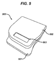
ここで図5を参照すると、放射線消毒ベースユニット500が閉鎖位置で示される。放射線消毒ベース部501は、図示の実施形態では、蓋502によって覆われており、蓋502は、放射線消毒ベース部501とヒンジ結合して、放射線消毒ベース部501の上面を覆って折り重ねられる。他の実施形態もまた、本発明の範囲内にある。図示のように、ディスプレイ503が、蓋502内に配置され、放射線消毒ベースユニット500によって実行されている消毒周期又は手順の表示を提供することができる。
Referring now to FIG. 5, radiation
結論
本発明は、上述のように、また以下の特許請求の範囲によって更に規定されるように、眼用レンズを消毒するための装置を提供する。
Conclusion The present invention provides an apparatus for disinfecting an ophthalmic lens as described above and as further defined by the following claims.
〔実施の態様〕
(1) 1つ又は2つ以上の眼用レンズを保管するための、眼用レンズ保管ケースを、受容するためのベース部であって、前記ベース部は、
眼用レンズ保管ケースを受容するための収容部と、
前記眼用レンズ保管ケース内の眼用レンズ保管区画に、消毒放射線を提供する、消毒放射線の供給源と、を含む、ベース部。
(2) 前記眼用レンズ保管区画に向けて、消毒放射線を反射するための反射表面を更に含む、実施態様1に記載のベース部。
(3) 前記消毒放射線の供給源と前記眼用レンズ保管区画とを位置合わせするための、位置合わせ機構を更に含む、実施態様1に記載のベース部。
(4) 前記位置合わせ機構が位置合わせ支柱を含む、実施態様3に記載のベース部。
(5) 前記位置合わせ支柱が、レンズ保管ケースのキャップの陥凹部内に適合する、環状の支柱を含む、実施態様4に記載のベース部。
(6) 前記位置合わせ支柱が、1つ又は2つ以上の消毒放射線の供給源を含む、実施態様5に記載のベース部。
(7) 前記1つ又は2つ以上の消毒放射線の供給源が、紫外発光ダイオードを含む、実施態様6に記載のベース部。
(8) 前記紫外発光ダイオードが、250ナノメートル〜280ナノメートルの周波数で放射を放出する、実施態様7に記載のベース部。
(9) 前記放出される消毒放射線が、前記保管区画内に保管された眼用レンズ上の微生物を死滅させるために十分である、実施態様1に記載のベース部。
(10) 前記保管ケース内に保管された眼用レンズに向けて、消毒放射線を方向付けるための光学素子を更に含む、実施態様1に記載のベース部。
Embodiment
(1) A base portion for receiving an ophthalmic lens storage case for storing one or more ophthalmic lenses, wherein the base portion includes:
A receiving portion for receiving the ophthalmic lens storage case;
Wherein the ophthalmic lens storage compartment intraocular lens storage case, comprising providing a disinfecting radiation, a source of disinfecting radiation, the base portion.
(2) the toward the ophthalmic lens storage compartment, further comprising a reflective surface for reflecting disinfecting radiation, the base portion of claim 1.
(3) the disinfection radiation for aligning the supply source and said ophthalmic lens storage compartment, further comprising an alignment mechanism, the base portion of claim 1.
(4) The base part according to embodiment 3, wherein the alignment mechanism includes an alignment column.
(5) The base portion according to embodiment 4, wherein the alignment strut includes an annular strut that fits within a recess in the cap of the lens storage case.
(6) the alignment post includes a source of one or more sterilization radiation, the base unit according to claim 5.
(7) the supply of one or more sterilization radiation comprises ultraviolet light-emitting diode, the base unit according to claim 6.
8. The base of embodiment 7, wherein the ultraviolet light emitting diode emits radiation at a frequency of 250 nanometers to 280 nanometers.
(9) The disinfectant radiation emitted is the is sufficient to kill microorganisms on ophthalmic lenses that are stored in the storage compartment, the base portion of claim 1.
(10) toward the ophthalmic lens that is stored in the storage case further comprises optical elements for directing disinfecting radiation, the base portion of claim 1.
(11) 前記消毒放射線の発生を制御するためのプロセッサを更に含む、実施態様1に記載のベース部。
(12) 前記消毒放射線が提供される期間が、前記プロセッサによって生成される論理制御信号に基づく、実施態様11に記載のベース部。
(13) 前記消毒放射線が提供される強度が、前記プロセッサによって生成される論理制御信号に基づく、実施態様11に記載のベース部。
(14) 前記消毒放射線の供給源の動作に基づいて、可聴信号を提供するように動作する、音響構成要素を更に含む、実施態様11に記載のベース部。
(15) 前記プロセッサによって伝送されるデジタルデータに基づいて、消毒プロセスの状況を表示するためのディスプレイを更に含む、実施態様11に記載のベース部。
(16) 前記消毒プロセスに関する情報を記憶するための、デジタル記憶装置を更に含む、実施態様11に記載のベース部。
(17) 保管ベース部内に定置された前記保管ケースに、機械的運動を提供するための、振動発生装置を更に含む、実施態様1に記載のベース部。
(18) 前記振動発生装置が圧電機構を含む、実施態様17に記載のベース部。
(19) 前記圧電機構がプロセッサによって生成される論理信号に基づいて動作する、実施態様17に記載のベース部。
(20) 前記プロセッサ及び前記デジタル記憶装置の一方若しくは双方と、個人用処理装置との間に、論理通信を提供するための、ユニバーサルシリアルバスコネクタを更に含む、実施態様16に記載のベース部。
(11) further includes a processor for controlling generation of the disinfecting radiation, the base portion of claim 1.
(12) period in which the disinfecting radiation is provided, based on the logic control signals generated by the processor, base portion according to claim 11.
(13) the intensity of the sterilization radiation is provided, based on the logic control signals generated by the processor, base portion according to claim 11.
(14) on the basis of the operation of the source of disinfecting radiation, operative to provide an audible signal, further comprising an acoustic component, base unit according to claim 11.
15. The base of embodiment 11, further comprising a display for displaying the status of the disinfection process based on the digital data transmitted by the processor.
16. The base of embodiment 11 further comprising a digital storage device for storing information regarding the disinfection process.
(17) The base part according to embodiment 1, further comprising a vibration generating device for providing mechanical movement to the storage case placed in the storage base part.
(18) The base part according to embodiment 17, wherein the vibration generating device includes a piezoelectric mechanism.
(19) The base unit according to embodiment 17, wherein the piezoelectric mechanism operates based on a logic signal generated by a processor.
20. The base of embodiment 16, further comprising a universal serial bus connector for providing logical communication between one or both of the processor and the digital storage device and a personal processing device.
(21) 保管ベース部を動作させるための電流を提供するための、ユニバーサルシリアルバスコネクタを更に含む、実施態様16に記載のベース部。
(22) 保管ベース部を動作させる電力を貯蔵するための、蓄電装置を更に含む、実施態様1に記載のベース部。
(23) 前記蓄電装置が、1つ又は2つ以上の再充電可能バッテリーを含む、実施態様22に記載のベース部。
(24) 前記蓄電装置が、1つ又は2つ以上のリチウムイオンバッテリーを含む、実施態様23に記載のベース部。
(25) 放射のパターンが、前記プロセッサからの信号に基づく、実施態様12に記載のベース部。
21. The base portion according to embodiment 16, further comprising a universal serial bus connector for providing a current for operating the storage base portion.
(22) The base unit according to embodiment 1, further comprising a power storage device for storing electric power for operating the storage base unit.
(23) The base unit according to embodiment 22, wherein the power storage device includes one or more rechargeable batteries.
(24) The base unit according to embodiment 23, wherein the power storage device includes one or more lithium ion batteries.
25. The base of embodiment 12, wherein the radiation pattern is based on a signal from the processor.
Claims (23)
眼用レンズ保管ケースを受容するための収容部を含むベース部と、
前記ベース部の上に折り重ねられるように前記ベース部にヒンジ結合される蓋と、
前記眼用レンズ保管ケース内の眼用レンズ保管区画に、消毒放射線を提供する、消毒放射線の供給源と、
前記消毒放射線の供給源と前記眼用レンズ保管区画とを位置合わせするための、位置合わせ機構とを含み、
前記位置合わせ機構が位置合わせ支柱を含み、前記位置合わせ支柱が、前記眼用レンズ保管ケースのキャップの陥凹部内に適合する環状の支柱を含む、ベースユニット。 For storing one or more ophthalmic lenses, the lens storage case for eye, a base unit for receiving the base unit,
A base including an accommodating portion for receiving an ophthalmic lens storage case;
A lid hinged to the base portion to be folded over the base portion;
A source of disinfecting radiation that provides disinfecting radiation to the ophthalmic lens storage compartment in the ophthalmic lens storage case;
An alignment mechanism for aligning the source of disinfecting radiation and the ophthalmic lens storage compartment;
The base unit , wherein the alignment mechanism includes an alignment column, and the alignment column includes an annular column that fits within a recess in the cap of the ophthalmic lens storage case.
請求項1〜21のいずれかに記載のベースユニットと、
1つ又は2つ以上の眼用レンズを保管するための、前記眼用レンズ保管ケースと、
を含む、システム。 A system for disinfecting ophthalmic lenses,
The base unit according to any one of claims 1 to 21 ,
The ophthalmic lens storage case for storing one or more ophthalmic lenses ;
Including the system.
Applications Claiming Priority (5)
| Application Number | Priority Date | Filing Date | Title |
|---|---|---|---|
| US34616210P | 2010-05-19 | 2010-05-19 | |
| US61/346,162 | 2010-05-19 | ||
| US12/961,616 | 2010-12-07 | ||
| US12/961,616 US20110284764A1 (en) | 2010-05-19 | 2010-12-07 | Ophthalmic lens disinfecting base |
| PCT/US2011/036826 WO2011146497A1 (en) | 2010-05-19 | 2011-05-17 | Ophthalmic lens disinfecting base |
Publications (3)
| Publication Number | Publication Date |
|---|---|
| JP2013532004A JP2013532004A (en) | 2013-08-15 |
| JP2013532004A5 JP2013532004A5 (en) | 2015-06-18 |
| JP5889879B2 true JP5889879B2 (en) | 2016-03-22 |
Family
ID=44971724
Family Applications (2)
| Application Number | Title | Priority Date | Filing Date |
|---|---|---|---|
| JP2013511298A Expired - Fee Related JP5989638B2 (en) | 2010-05-19 | 2011-05-17 | Light-emitting diode disinfection base for ophthalmic lenses |
| JP2013511297A Expired - Fee Related JP5889879B2 (en) | 2010-05-19 | 2011-05-17 | Ophthalmic lens disinfection base |
Family Applications Before (1)
| Application Number | Title | Priority Date | Filing Date |
|---|---|---|---|
| JP2013511298A Expired - Fee Related JP5989638B2 (en) | 2010-05-19 | 2011-05-17 | Light-emitting diode disinfection base for ophthalmic lenses |
Country Status (13)
| Country | Link |
|---|---|
| US (2) | US20110284764A1 (en) |
| EP (2) | EP2571538B1 (en) |
| JP (2) | JP5989638B2 (en) |
| KR (2) | KR101838871B1 (en) |
| CN (2) | CN102892436B (en) |
| AR (2) | AR084689A1 (en) |
| AU (2) | AU2011256273B2 (en) |
| BR (2) | BR112012029439B1 (en) |
| CA (2) | CA2799946C (en) |
| RU (2) | RU2577303C2 (en) |
| SG (4) | SG10201503900TA (en) |
| TW (2) | TW201200167A (en) |
| WO (1) | WO2011146497A1 (en) |
Cited By (1)
| Publication number | Priority date | Publication date | Assignee | Title |
|---|---|---|---|---|
| KR102041785B1 (en) * | 2018-07-20 | 2019-11-07 | (주)E.O.S | UV irradiation device for contact lenses |
Families Citing this family (12)
| Publication number | Priority date | Publication date | Assignee | Title |
|---|---|---|---|---|
| US20110284764A1 (en) | 2010-05-19 | 2011-11-24 | Pugh Randall B | Ophthalmic lens disinfecting base |
| US20110284773A1 (en) | 2010-05-19 | 2011-11-24 | Pugh Randall B | Germicidal bulb disinfection base for ophthalmic lenses |
| US9024276B2 (en) * | 2010-06-23 | 2015-05-05 | Johnson & Johnson Vision Care, Inc. | Contact lens storage case surface disinfection |
| US8969830B2 (en) | 2010-12-07 | 2015-03-03 | Johnson & Johnson Vision Care, Inc. | Ophthalmic lens disinfecting base unit with programmable and communication elements |
| US8942841B2 (en) | 2011-12-06 | 2015-01-27 | Johnson & Johnson Vision Care, Inc | Lens storage unit with programmable and communication elements for monitoring the condition of lenses and their response to geo-social phenomena |
| AU2013217066B2 (en) * | 2012-02-10 | 2016-08-11 | Johnson & Johnson Vision Care, Inc. | An Ophthalmic lens storing unit with programmable and communication elements for monitoring the use and automated ordering |
| CN102636883A (en) * | 2012-04-06 | 2012-08-15 | 珠海视光科技有限公司 | Automatic corneal contact lens cleaner |
| US20150366311A1 (en) * | 2014-06-19 | 2015-12-24 | Coopervision International Holding Company, Lp | Protection of Contact Lenses from Microbial Contamination Caused by Handling |
| US10180248B2 (en) | 2015-09-02 | 2019-01-15 | ProPhotonix Limited | LED lamp with sensing capabilities |
| CN106579703B (en) * | 2016-12-15 | 2018-01-12 | 济南市儿童医院 | A kind of pupil macrophotograph sterilization dipping storage device |
| EP3556243A1 (en) * | 2018-04-19 | 2019-10-23 | Cornelius Doniga | Contact lens storage and cleaning container |
| US11852899B2 (en) | 2020-10-06 | 2023-12-26 | International Business Machines Corporation | Ultrasound emitting contact lens |
Family Cites Families (82)
| Publication number | Priority date | Publication date | Assignee | Title |
|---|---|---|---|---|
| US3621855A (en) | 1969-09-30 | 1971-11-23 | Ellar Products Inc | Article cleaning and storage unit |
| US3852032A (en) | 1971-06-07 | 1974-12-03 | Uroptics Int Inc | Process for sterilizing hydrophilic gelatin lenses having ultraviolet stabilizers |
| CA1010224A (en) | 1973-02-12 | 1977-05-17 | Neville A. Baron | Asepticizing of contact lenses |
| US3978341A (en) | 1974-04-10 | 1976-08-31 | E. I. Du Pont De Nemours And Company | Short wavelength ultraviolet irradiation treatment of polymeric surfaces |
| US4270039A (en) * | 1979-08-17 | 1981-05-26 | Rincon Industries, Inc. | Heating unit with indicator for disinfecting soft lenses, or the like |
| US4412834A (en) | 1981-06-05 | 1983-11-01 | Baxter Travenol Laboratories | Antimicrobial ultraviolet irradiation of connector for continuous ambulatory peritoneal dialysis |
| US4529868A (en) | 1981-11-02 | 1985-07-16 | John G. Bowen | Soft contact lens disinfecting unit |
| US4545479A (en) * | 1984-08-13 | 1985-10-08 | Figari Alberto A | Contact lens carrying case with magnifying aid apparatus |
| FR2583531B1 (en) * | 1985-06-12 | 1988-11-04 | Ituarte Angel | METHOD AND APPARATUS FOR CLEANING AND STERILIZING CONTACT LENSES. |
| FR2599255B1 (en) * | 1986-05-30 | 1993-07-02 | Chartier Alain | PROCESS AND APPARATUS FOR CLEANING AND STERILIZATION OF PRODUCTS SENSITIVE TO THE EFFECTS OF HEAT AND CHEMICAL AGENTS, IN PARTICULAR CONTACT LENSES. |
| JPH0649059B2 (en) * | 1987-04-20 | 1994-06-29 | 株式会社豊振科学産業所 | Sanitary equipment |
| US4868397A (en) * | 1987-10-09 | 1989-09-19 | Tittel Paul G | Sterilizing apparatus for ophthalmological devices |
| US5387404A (en) * | 1988-04-21 | 1995-02-07 | Flexiclave, Inc. | Process and apparatus for heat disinfecting soft contact lenses |
| JPH0394758A (en) * | 1989-09-08 | 1991-04-19 | Nippon Contact Lens Kk | Method and device for sterilizing contact lens |
| JPH03100828A (en) | 1989-09-14 | 1991-04-25 | Matsushita Electric Ind Co Ltd | Addition circuit |
| JPH03131738A (en) | 1989-10-18 | 1991-06-05 | Hitachi Ltd | Monitoring device for electric car |
| US5120499A (en) * | 1990-01-11 | 1992-06-09 | U. V. Black Box Corporation | Method and system for asepticizing contact lenses and storing device |
| AU642768B2 (en) | 1990-10-02 | 1993-10-28 | Ciba-Geigy Ag | A method of surface-cleaning and/or sterilising optical components, especially contact lenses |
| US5144144A (en) * | 1991-07-19 | 1992-09-01 | American Vision, Inc. | Contact lens cleaning and disinfecting system |
| US5178173A (en) * | 1991-08-01 | 1993-01-12 | Robert J. Pace | Ultrasonic contact lens cleaning device |
| JP3100828B2 (en) | 1993-04-27 | 2000-10-23 | 帝人化成株式会社 | Modified aromatic polycarbonate resin and production method thereof |
| US5440458A (en) | 1993-11-02 | 1995-08-08 | Volk; Donald A. | Illuminated lens case |
| JP2754331B2 (en) * | 1994-03-31 | 1998-05-20 | 岡谷電機産業株式会社 | Washing machine |
| TW266267B (en) | 1994-08-23 | 1995-12-21 | Ciba Geigy | Process for sterilizing articles and providing sterile storage environments |
| JPH0866678A (en) * | 1994-08-30 | 1996-03-12 | Tadahide Iwashita | Small-sized sterilization device |
| DE29509210U1 (en) * | 1995-06-03 | 1995-08-24 | Leach James L | Device for disinfecting and cleaning objects |
| GB9606438D0 (en) * | 1996-03-27 | 1996-06-05 | Jenton R A & Co Ltd | Contact lens sterilisation |
| US5927304A (en) * | 1996-08-05 | 1999-07-27 | Wen; Sheree H. | Food article washer |
| JP3736587B2 (en) * | 1996-09-20 | 2006-01-18 | アタム技研株式会社 | Cleaning and disinfection unit |
| JPH11385A (en) | 1997-04-17 | 1999-01-06 | Menicon Co Ltd | Sterilizing method for intraocular lens |
| US6039928A (en) | 1998-01-28 | 2000-03-21 | Roberts; Jon L. | Writing implement sterilization apparatus |
| BR9916580A (en) * | 1998-12-23 | 2001-09-25 | Richard A Eckhardt | Process and apparatus for sterilizing small objects |
| AU1954600A (en) * | 1999-03-01 | 2000-09-07 | Johnson & Johnson Vision Care, Inc. | Method of sterilization |
| US7879288B2 (en) * | 1999-03-01 | 2011-02-01 | Johnson & Johnson Vision Care, Inc. | Method and apparatus of sterilization using monochromatic UV radiation source |
| US6592816B1 (en) * | 1999-03-01 | 2003-07-15 | Johnson & Johnson Vision Care, Inc. | Sterilization system |
| SG93245A1 (en) * | 1999-07-13 | 2002-12-17 | Johnson & Johnson Vision Care | Reflectors for uv radiation source |
| US6318151B1 (en) * | 1999-07-26 | 2001-11-20 | Abbott Laboratories | Self-contained sterilant monitoring assembly and method of using same |
| JP4481470B2 (en) | 1999-11-01 | 2010-06-16 | 株式会社メニコン | Contact lens disinfection method and disinfectant for the same |
| JP2001188207A (en) * | 1999-12-27 | 2001-07-10 | Seimoku Rin | Washing and sterilizing device for contact lens |
| KR20010092892A (en) | 2000-03-27 | 2001-10-27 | 임성묵 | Apparatus for washing contact lenses |
| US6652816B2 (en) * | 2000-09-23 | 2003-11-25 | Hyeon-Bae Hwang | Apparatus for generating ozone and anion |
| JP2002126050A (en) * | 2000-10-20 | 2002-05-08 | Nippon Optical:Kk | Disinfecting device for contact lens case and storage container for contact lens case |
| US20040234569A1 (en) | 2001-08-20 | 2004-11-25 | Kazuhiko Nakada | Disinfection method |
| JP2003093481A (en) * | 2001-09-25 | 2003-04-02 | Menicon Co Ltd | Sterilizing and disinfecting device for contact lens |
| TW519899U (en) | 2002-06-13 | 2003-02-01 | Chin-Liang Lin | Air screen device for eye examination instrument |
| JP2004159676A (en) * | 2002-11-08 | 2004-06-10 | Matsushita Electric Works Ltd | Sterilizer |
| JP2004275335A (en) * | 2003-03-14 | 2004-10-07 | Univ Nihon | Optical sterilization method by scintillation pulse and its apparatus |
| US6981946B2 (en) | 2003-04-17 | 2006-01-03 | J.D. Mueller Company, Llc | Load sensing applanation tonometer |
| US20050028848A1 (en) * | 2003-08-04 | 2005-02-10 | Jung-Hua Lai | Contact lens cleansing unit |
| CN2662285Y (en) * | 2003-08-25 | 2004-12-08 | 赖荣华 | Conserve device for contact lens |
| JP3100828U (en) * | 2003-10-02 | 2004-05-27 | 榮華 ▲頼▼ | Contact lens maintenance equipment |
| KR100423950B1 (en) | 2003-10-22 | 2004-03-22 | 오태환 | Portable toothbrush sterilizer that have USB port |
| TWM256699U (en) | 2003-11-07 | 2005-02-11 | Jr-Fang Luo | Mold structure for rapid producing shoe mold |
| BRPI0506680A (en) * | 2004-02-11 | 2007-05-02 | Barry Ressler | system and method for sterilization using UV light source (s) |
| JP4263213B2 (en) | 2004-03-17 | 2009-05-13 | 横浜ゴム株式会社 | Antenna device |
| KR100586927B1 (en) * | 2004-05-17 | 2006-06-09 | 황현철 | disinfection and washing apparatus of lens |
| US7993580B2 (en) * | 2004-08-24 | 2011-08-09 | Baxter International Inc. | Methods for the inactivation of microorganisms in biological fluids, flow through reactors and methods of controlling the light sum dose to effectively inactivate microorganisms in batch reactors |
| DE602006018909D1 (en) | 2005-03-31 | 2011-01-27 | Johnson & Johnson Vision Care | CONNECTION OF CONTACT LENS PACKAGES |
| KR101401833B1 (en) * | 2005-10-18 | 2014-05-29 | 도레이 카부시키가이샤 | Microporous film for power storage device separator and power storage device separator making use of the same |
| WO2007051276A1 (en) * | 2005-11-03 | 2007-05-10 | Uv Light Sciences Group, Inc. | Uv sterilizing wand |
| WO2007056591A1 (en) | 2005-11-09 | 2007-05-18 | Coopervision Inc. | Methods for sterilizing silicone hydrogel contact lenses |
| KR100803383B1 (en) | 2005-11-10 | 2008-02-15 | 국현민 | A sterilizer for toothbrush |
| US20090274576A1 (en) | 2006-01-18 | 2009-11-05 | Barry Ressler | System and method for container sterilization using UV light source |
| US20070206377A1 (en) * | 2006-03-06 | 2007-09-06 | Mark Borup | Contact lens case |
| RU57423U1 (en) | 2006-05-11 | 2006-10-10 | Юрий Афанасьевич Зыкин | INDIVIDUAL ACCUMULATOR LAMP |
| RU69323U1 (en) | 2007-07-25 | 2007-12-10 | Открытое акционерное общество "Аккумуляторная компания "Ригель" | LITHIUM ION BATTERY |
| TWM329760U (en) | 2007-08-30 | 2008-04-01 | Tai Ye Technology Co Ltd | Isothermal plate using wick structure for positioning supporting body |
| RU2010116725A (en) * | 2007-09-28 | 2011-11-10 | Джонсон Энд Джонсон Вижн Кэа, Инк. (Us) | METHODS OF STERILIZATION OF OPHTHALMIC LENSES BY UV RADIATION |
| US20090096351A1 (en) | 2007-10-12 | 2009-04-16 | Cabot Corporation | Reflective layers for electronic devices |
| EP2067491A1 (en) | 2007-12-04 | 2009-06-10 | Givaudan SA | USB-powered air-freshener |
| US8378324B2 (en) | 2008-02-07 | 2013-02-19 | William G. Gardner, III | Handheld portable multi purpose sterilizing wavelength transforming converter |
| US20090256085A1 (en) | 2008-04-11 | 2009-10-15 | Devaraj Thiruppathi | Ultra-violet sponge holder |
| US8277741B2 (en) * | 2008-10-28 | 2012-10-02 | Mccabe Colin Adam | Anti-germicidal and/or antimicrobial apparatus for reducing and/or eliminating germs and/or bacteria from the soles of footwear and method for use |
| US20100279124A1 (en) | 2008-10-31 | 2010-11-04 | Leybold Optics Gmbh | Hafnium or zirconium oxide Coating |
| US20100266445A1 (en) | 2009-04-21 | 2010-10-21 | Kenneth L. Campagna | Portable antimicrobial ultra violet sterilizer |
| TWM367032U (en) | 2009-06-25 | 2009-10-21 | zhi-xian Wu | Dual shockwave cleaning machine |
| US8528728B2 (en) * | 2010-05-19 | 2013-09-10 | Johnson & Johnson Vision Care, Inc. | Ophthalmic lens disinfecting storage case |
| US20110284764A1 (en) | 2010-05-19 | 2011-11-24 | Pugh Randall B | Ophthalmic lens disinfecting base |
| US9282796B2 (en) | 2010-05-19 | 2016-03-15 | Johnson & Johnson Vision Care, Inc. | UV radiation control for disinfecting of ophthalmic lenses |
| US20110284773A1 (en) * | 2010-05-19 | 2011-11-24 | Pugh Randall B | Germicidal bulb disinfection base for ophthalmic lenses |
| US8969830B2 (en) | 2010-12-07 | 2015-03-03 | Johnson & Johnson Vision Care, Inc. | Ophthalmic lens disinfecting base unit with programmable and communication elements |
| JP5628763B2 (en) | 2011-08-02 | 2014-11-19 | 日本電信電話株式会社 | Method and apparatus for fusion splicing of optical fiber by CO laser |
-
2010
- 2010-12-07 US US12/961,616 patent/US20110284764A1/en not_active Abandoned
-
2011
- 2011-05-17 AU AU2011256273A patent/AU2011256273B2/en not_active Ceased
- 2011-05-17 EP EP11724328.7A patent/EP2571538B1/en not_active Not-in-force
- 2011-05-17 SG SG10201503900TA patent/SG10201503900TA/en unknown
- 2011-05-17 WO PCT/US2011/036826 patent/WO2011146497A1/en active Application Filing
- 2011-05-17 CN CN201180024719.3A patent/CN102892436B/en not_active Expired - Fee Related
- 2011-05-17 SG SG10201503901RA patent/SG10201503901RA/en unknown
- 2011-05-17 SG SG2012084422A patent/SG185610A1/en unknown
- 2011-05-17 CN CN201180024794.XA patent/CN102905731B/en not_active Expired - Fee Related
- 2011-05-17 CA CA2799946A patent/CA2799946C/en not_active Expired - Fee Related
- 2011-05-17 EP EP11724329A patent/EP2571539A1/en not_active Withdrawn
- 2011-05-17 JP JP2013511298A patent/JP5989638B2/en not_active Expired - Fee Related
- 2011-05-17 JP JP2013511297A patent/JP5889879B2/en not_active Expired - Fee Related
- 2011-05-17 SG SG2012084455A patent/SG185613A1/en unknown
- 2011-05-17 RU RU2012155004/15A patent/RU2577303C2/en not_active IP Right Cessation
- 2011-05-17 RU RU2012154891/15A patent/RU2012154891A/en unknown
- 2011-05-17 CA CA2799950A patent/CA2799950A1/en not_active Abandoned
- 2011-05-17 BR BR112012029439-3A patent/BR112012029439B1/en not_active IP Right Cessation
- 2011-05-17 KR KR1020127032700A patent/KR101838871B1/en active IP Right Grant
- 2011-05-17 AU AU2011256277A patent/AU2011256277B2/en not_active Ceased
- 2011-05-17 BR BR112012029420A patent/BR112012029420A2/en not_active Application Discontinuation
- 2011-05-17 KR KR1020127032711A patent/KR20130079438A/en not_active Application Discontinuation
- 2011-05-18 TW TW100117318A patent/TW201200167A/en unknown
- 2011-05-18 TW TW100117317A patent/TW201206507A/en unknown
- 2011-05-19 AR ARP110101723A patent/AR084689A1/en unknown
- 2011-05-19 AR ARP110101722A patent/AR084688A1/en unknown
-
2016
- 2016-03-10 US US15/066,071 patent/US9795704B2/en active Active
Cited By (1)
| Publication number | Priority date | Publication date | Assignee | Title |
|---|---|---|---|---|
| KR102041785B1 (en) * | 2018-07-20 | 2019-11-07 | (주)E.O.S | UV irradiation device for contact lenses |
Also Published As
Similar Documents
| Publication | Publication Date | Title |
|---|---|---|
| JP5889879B2 (en) | Ophthalmic lens disinfection base | |
| US9833535B2 (en) | Contact lens storage case surface disinfection | |
| JP5992400B2 (en) | Sterilization valve disinfection base for ophthalmic lenses | |
| JP6316868B2 (en) | Ophthalmic lens disinfection storage case | |
| AU2015203093A1 (en) | Light emitting diode disinfection base for ophthalmic lens |
Legal Events
| Date | Code | Title | Description |
|---|---|---|---|
| A621 | Written request for application examination |
Free format text: JAPANESE INTERMEDIATE CODE: A621 Effective date: 20140422 |
|
| A977 | Report on retrieval |
Free format text: JAPANESE INTERMEDIATE CODE: A971007 Effective date: 20150113 |
|
| A131 | Notification of reasons for refusal |
Free format text: JAPANESE INTERMEDIATE CODE: A131 Effective date: 20150210 |
|
| A524 | Written submission of copy of amendment under section 19 (pct) |
Free format text: JAPANESE INTERMEDIATE CODE: A524 Effective date: 20150427 |
|
| A521 | Written amendment |
Free format text: JAPANESE INTERMEDIATE CODE: A523 Effective date: 20150428 |
|
| A131 | Notification of reasons for refusal |
Free format text: JAPANESE INTERMEDIATE CODE: A131 Effective date: 20151027 |
|
| A521 | Written amendment |
Free format text: JAPANESE INTERMEDIATE CODE: A523 Effective date: 20160120 |
|
| TRDD | Decision of grant or rejection written | ||
| A01 | Written decision to grant a patent or to grant a registration (utility model) |
Free format text: JAPANESE INTERMEDIATE CODE: A01 Effective date: 20160209 |
|
| A61 | First payment of annual fees (during grant procedure) |
Free format text: JAPANESE INTERMEDIATE CODE: A61 Effective date: 20160217 |
|
| R150 | Certificate of patent or registration of utility model |
Ref document number: 5889879 Country of ref document: JP Free format text: JAPANESE INTERMEDIATE CODE: R150 |
|
| R250 | Receipt of annual fees |
Free format text: JAPANESE INTERMEDIATE CODE: R250 |
|
| LAPS | Cancellation because of no payment of annual fees |