EP2571538B1 - Ophthalmic lens disinfecting base - Google Patents
Ophthalmic lens disinfecting base Download PDFInfo
- Publication number
- EP2571538B1 EP2571538B1 EP11724328.7A EP11724328A EP2571538B1 EP 2571538 B1 EP2571538 B1 EP 2571538B1 EP 11724328 A EP11724328 A EP 11724328A EP 2571538 B1 EP2571538 B1 EP 2571538B1
- Authority
- EP
- European Patent Office
- Prior art keywords
- disinfecting
- radiation
- storage case
- ophthalmic lens
- base unit
- Prior art date
- Legal status (The legal status is an assumption and is not a legal conclusion. Google has not performed a legal analysis and makes no representation as to the accuracy of the status listed.)
- Not-in-force
Links
- 230000000249 desinfective effect Effects 0.000 title claims description 106
- 230000005855 radiation Effects 0.000 claims description 116
- 238000003860 storage Methods 0.000 claims description 69
- 230000007246 mechanism Effects 0.000 claims description 9
- 238000004891 communication Methods 0.000 claims description 7
- 238000000034 method Methods 0.000 claims description 7
- 241000894006 Bacteria Species 0.000 description 5
- 239000000017 hydrogel Substances 0.000 description 5
- 241000233866 Fungi Species 0.000 description 4
- 239000000463 material Substances 0.000 description 4
- 239000004033 plastic Substances 0.000 description 4
- 229920003023 plastic Polymers 0.000 description 4
- 241000700605 Viruses Species 0.000 description 3
- 238000012937 correction Methods 0.000 description 2
- 239000002537 cosmetic Substances 0.000 description 2
- 239000000645 desinfectant Substances 0.000 description 2
- 239000011521 glass Substances 0.000 description 2
- 238000002347 injection Methods 0.000 description 2
- 239000007924 injection Substances 0.000 description 2
- 238000005304 joining Methods 0.000 description 2
- 230000003287 optical effect Effects 0.000 description 2
- 239000000243 solution Substances 0.000 description 2
- 239000000126 substance Substances 0.000 description 2
- WKBPZYKAUNRMKP-UHFFFAOYSA-N 1-[2-(2,4-dichlorophenyl)pentyl]1,2,4-triazole Chemical compound C=1C=C(Cl)C=C(Cl)C=1C(CCC)CN1C=NC=N1 WKBPZYKAUNRMKP-UHFFFAOYSA-N 0.000 description 1
- 238000010146 3D printing Methods 0.000 description 1
- 244000050403 Iris x germanica Species 0.000 description 1
- HBBGRARXTFLTSG-UHFFFAOYSA-N Lithium ion Chemical compound [Li+] HBBGRARXTFLTSG-UHFFFAOYSA-N 0.000 description 1
- 240000007320 Pinus strobus Species 0.000 description 1
- FAPWRFPIFSIZLT-UHFFFAOYSA-M Sodium chloride Chemical compound [Na+].[Cl-] FAPWRFPIFSIZLT-UHFFFAOYSA-M 0.000 description 1
- 230000002411 adverse Effects 0.000 description 1
- 230000004075 alteration Effects 0.000 description 1
- 238000013459 approach Methods 0.000 description 1
- QVGXLLKOCUKJST-UHFFFAOYSA-N atomic oxygen Chemical compound [O] QVGXLLKOCUKJST-UHFFFAOYSA-N 0.000 description 1
- 239000011248 coating agent Substances 0.000 description 1
- 238000000576 coating method Methods 0.000 description 1
- -1 cyclic olefins Chemical class 0.000 description 1
- 238000011161 development Methods 0.000 description 1
- 230000018109 developmental process Effects 0.000 description 1
- 238000010586 diagram Methods 0.000 description 1
- 230000004384 eye physiology Effects 0.000 description 1
- 238000001746 injection moulding Methods 0.000 description 1
- 229910001416 lithium ion Inorganic materials 0.000 description 1
- 238000001459 lithography Methods 0.000 description 1
- 238000004519 manufacturing process Methods 0.000 description 1
- 229910052751 metal Inorganic materials 0.000 description 1
- 239000002184 metal Substances 0.000 description 1
- 230000000813 microbial effect Effects 0.000 description 1
- 238000012986 modification Methods 0.000 description 1
- 230000004048 modification Effects 0.000 description 1
- NJPPVKZQTLUDBO-UHFFFAOYSA-N novaluron Chemical compound C1=C(Cl)C(OC(F)(F)C(OC(F)(F)F)F)=CC=C1NC(=O)NC(=O)C1=C(F)C=CC=C1F NJPPVKZQTLUDBO-UHFFFAOYSA-N 0.000 description 1
- 229910052760 oxygen Inorganic materials 0.000 description 1
- 239000001301 oxygen Substances 0.000 description 1
- 230000035699 permeability Effects 0.000 description 1
- 229920001296 polysiloxane Polymers 0.000 description 1
- 230000000717 retained effect Effects 0.000 description 1
- 229920002379 silicone rubber Polymers 0.000 description 1
- 238000004659 sterilization and disinfection Methods 0.000 description 1
- 238000002211 ultraviolet spectrum Methods 0.000 description 1
- 230000000007 visual effect Effects 0.000 description 1
Images

Classifications
-
- A—HUMAN NECESSITIES
- A61—MEDICAL OR VETERINARY SCIENCE; HYGIENE
- A61L—METHODS OR APPARATUS FOR STERILISING MATERIALS OR OBJECTS IN GENERAL; DISINFECTION, STERILISATION OR DEODORISATION OF AIR; CHEMICAL ASPECTS OF BANDAGES, DRESSINGS, ABSORBENT PADS OR SURGICAL ARTICLES; MATERIALS FOR BANDAGES, DRESSINGS, ABSORBENT PADS OR SURGICAL ARTICLES
- A61L12/00—Methods or apparatus for disinfecting or sterilising contact lenses; Accessories therefor
- A61L12/02—Methods or apparatus for disinfecting or sterilising contact lenses; Accessories therefor using physical phenomena, e.g. electricity, ultrasonics or ultrafiltration
- A61L12/06—Radiation, e.g. ultraviolet or microwaves
- A61L12/063—Ultraviolet radiation
-
- A—HUMAN NECESSITIES
- A45—HAND OR TRAVELLING ARTICLES
- A45C—PURSES; LUGGAGE; HAND CARRIED BAGS
- A45C11/00—Receptacles for purposes not provided for in groups A45C1/00-A45C9/00
-
- A—HUMAN NECESSITIES
- A45—HAND OR TRAVELLING ARTICLES
- A45C—PURSES; LUGGAGE; HAND CARRIED BAGS
- A45C11/00—Receptacles for purposes not provided for in groups A45C1/00-A45C9/00
- A45C11/005—Contact lens cases
Description
- This invention relates to a system for disinfecting ophthalmic lenses.
-
US2007/0206377A1 describes a contact lens case which includes a housing having at least one contact lens receiving receptacle, an electrical power source mounted to the housing; and at least one light emitting device mounted to the housing. At least a portion of the contact lens receiving receptacle is substantially light transmittable. When a contact lens is placed in a receptacle and light is emitted from the light emitting device, light is transferred through the receptacle and the contact lens is illuminated to improve visual detectability of the contact lens. - It is well known that contact lenses can be used to improve vision. Various contact lenses have been commercially produced for many years. Early designs of contact lenses were fashioned from hard materials. Although these lenses are still currently used in some applications, they are not suitable for all patients due to their poor comfort and relatively low permeability to oxygen. Later developments in the field gave rise to soft contact lenses, based upon hydrogels.
- Hydrogel contact lenses are very popular today. These lenses are often more comfortable to wear than contact lenses made of hard materials. Many hydrogel contact lenses may be worn for more than one day. However, a build-up of microbial life and bacteria on the lenses generally makes it desirable to periodically remove the lenses and disinfect them.
- Disinfection of contact lenses traditionally entails placing the contact lens in a container or case and subjecting the contact lens to a chemical disinfectant. However, chemical disinfectants are not always as efficacious as may be desired. From time to time, a contact lens with a bacterium, mold, fungus or other type of adverse life form is reinserted into a user's eye with the result being a diseased eye. In addition, disinfecting solutions tend to be expensive and add to the total cost of using contact lenses for vision correction or cosmetic enhancement. New methods and approaches are therefore needed to disinfect contact lenses.
- The invention is defined in the appended claims. The lens storage case is capable of receiving disinfecting radiation in a wavelength and intensity suitable to kill unwanted bacteria, viruses, molds, fungi and the like on a contact lens. The base is capable of providing disinfecting radiation in a wavelength and intensity suitable to kill the unwanted bacteria, viruses, molds, fungi and the like on a contact lens.
- In another aspect, in some embodiments, a disinfecting radiation base includes one or more reflective surfaces, such as a mirror, for reflecting disinfecting radiation towards an ophthalmic lens stored in a storage case mounted in the disinfecting radiation base.
-
-
FIG. 1 illustrates a lens storage case in a base unit according to some embodiments of the present invention. -
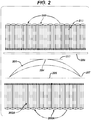
FIG. 2 illustrates some embodiments of alignment of a disinfecting radiation source with an ophthalmic lens in a lens storage case according to the present invention. -
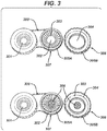
FIG. 3 illustrates a close up view of a storage case with one cap removed according to some embodiments of the present invention. -
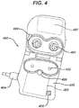
FIG. 4 illustrates aspects of a base unit according to some embodiments of the present invention. -
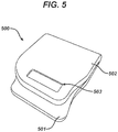
FIG. 5 illustrates a base unit in a closed state with a display. - The present invention includes methods and apparatus for disinfecting an ophthalmic lens. In addition, the present invention includes a storage case for holding an ophthalmic lens while it is disinfected with disinfecting radiation.
- In the following sections detailed descriptions of embodiments of the invention will be given. The description of both preferred and alternative embodiments are exemplary embodiments only, and it is understood that to those skilled in the art that variations, modifications and alterations may be apparent. It is therefore to be understood that said exemplary embodiments do not limit the scope of the underlying invention.
- In this description and claims directed to the presented invention, various terms may be used for which the following definitions will apply:
- Disinfecting Radiation: as used herein refers to a frequency and intensity of radiation sufficient to diminish the life expectancy of a life form receiving a Disinfecting Radiation Dose.
- Disinfecting Radiation Dose: as used herein refers to an amount of radiation to reduce an amount of life by at least two logs on a logarithmic scale and preferably three logs or more, wherein life includes at least bacteria, viruses, molds and fungi.
- Lens: refers to any ophthalmic device that resides in or on the eye. These devices can provide optical correction or may be cosmetic. For example, the term lens can refer to a contact lens, intraocular lens, overlay lens, ocular insert, optical insert or other similar device through which vision is corrected or modified, or through which eye physiology is cosmetically enhanced (e.g. iris color) without impeding vision. In some embodiments, the preferred lenses of the invention are soft contact lenses made from silicone elastomers or hydrogels, which include but are not limited to silicone hydrogels, and fluorohydrogels.
- Referring now to
Fig. 1 , an ophthalmic lens disinfecting system 100 is illustrated including a radiation disinfectingbase 101, a radiation disinfectingstorage case 102 and a disinfectingradiation source 103. According to the present invention, a radiation disinfectingstorage case 102 is positioned within the path of radiation from theradiation disinfecting source 103, such that one or more ophthalmic lenses stored within the radiation disinfectingstorage case 102 are exposed to radiation emanating from theradiation disinfecting source 103 and life forms existing on, or in proximity to, the ophthalmic lenses are exposed to the disinfecting radiation, provided by a radiation disinfecting source, and killed, essentially disinfecting the ophthalmic lens. - As illustrated, the radiation disinfecting
storage case 102 is positioned in an open state with a radiation disinfectingbase 101 and a lid 106. The radiation disinfectingstorage case 102 includes a positioning artifact 105 for aligning the disinfectingradiation source 103 with the radiation disinfectingstorage case 102. As illustrated, the positioning artifact 105 includes an annular depression for receiving an annular arrangement of disinfectingradiation source 103. Positioning artifacts 105 may include almost any polygon shaped depression. Other embodiments may include one or more alignment pins. In still other embodiments, a positioning artifact 105 may include a snap, a threaded joining or other removably fixed type of joining. - In some embodiments, the positioning artifact 105 aligns the radiation disinfecting
radiation source 103 in a position generally orthogonal to an apex of a contact lens stored within the radiation disinfectingstorage case 102. In additional embodiments, a positioning artifact 105 aligns the radiation disinfectingradiation source 103 in a position generally orthogonal to a plane extending across a bottom perimeter of a contact lens. - In another aspect, in some embodiments, the positioning artifact may also be capable of transmitting a vibrational frequency from a radiation disinfecting
base 101 to the radiation disinfectingstorage case 102 and ultimately to a lens stored within the radiation disinfectingstorage case 102. The vibrational frequency may be a frequency capable of causing expired life forms to be moved from within a path of radiation to an unexpired life form. Moving the expired life forms allows for more efficacious disinfecting by exposing more unexpired life forms to a direct path of radiation. - The radiation disinfecting
radiation source 103 may include one or more light emitting diodes (LEDs). In some preferred embodiments, the LEDs include ultraviolet (UV) emitting LEDs. Preferred embodiments include LEDs which emit light radiation with a wavelength of between about 250 nanometers of light radiation and about 280 nanometers of light radiation, preferably, the wavelength is between 250 nanometers and 275 nanometers, and most preferably 254 nanometers. - Referring now to
Fig. 2 , a block diagram illustrates some embodiments of alignment of a radiation disinfectingsource 200, such as one or more UV LEDs radiating disinfectingradiation 202 in the UV spectrum towards acontact lens 201. In some preferred embodiments, UV LEDs will be arranged such that a radiation disinfecting storage case will align in a specific position in relation to thecontact lens 201. The alignment is maintained via an alignment artifact. In some embodiments, a radiation disinfecting storage case is aligned todirect UV radiation 202 at an angle essentially orthogonal to aplane 203 touching anapex 204 of thecontact lens 201 retained in a radiation disinfecting storage case. - In other embodiments, radiation disinfecting storage case may be aligned to direct disinfecting
radiation 202A from one or more UV emitting LEDs 200A at an angle essentially orthogonal to aplane 205 across aperimeter edge 207 of thecontact lens 201. - In another aspect, in some embodiments, one or
more optics 208 may be used to focus disinfecting radiation onto a lens stored in a disinfecting radiation storage case. An optic may be included in a base or in a part of a storage case. - Referring now to
Fig. 3 , an exemplary a radiation disinfectingstorage case 300 is illustrated. The radiation disinfectingstorage case 300 includes one or more lens storage compartments 301. Astorage compartment 301 is capable of receiving and storing one or more ophthalmic lenses, such as a contact lens. - Some embodiments include one or more
lens alignment mechanisms 302 for positioning an ophthalmic lens stored in astorage compartment 301 included in a radiation disinfectingstorage case 300. Alens alignment mechanism 302 may include for example a pedestal with an arcuate surface generally of a similar size and shape as an inside dimension of an ophthalmic lens. A convex surface may include an arc generally equivalent to an arc of a concave surface of an ophthalmic lens to be stored within the radiation disinfectingstorage case 300. Other embodiments may include alens alignment mechanism 306 comprising a bowl generally of a similar size and shape as an outside dimension of an ophthalmic lens. - Preferred positioning aligns the stored lens in a direct path of disinfecting radiation. However, other embodiments may include one or
reflective surfaces 306. Areflective surface 306 may essentially include a mirror and be formed from a glass, a plastic, a metal or a coating that is functional to reflect disinfecting radiation in a direction desired. Generally, the direction will be towards a lens stored in astorage case 300 positioned in the base. In some embodiments,reflective surface 306 may be generally proximate to, and/or generally parallel to, a surface of a stored lens. Other embodiments may include areflective surface 306 generally around a perimeter of a stored lens. - One or more radiation windows 303-304 are included in the storage compartments 301. The radiation windows 303-304 provide portions of the radiation disinfecting storage case that are at least partially transparent to wavelengths of disinfecting radiation. Preferably the radiation windows 303-304 will be as close to 100% transparent as possible to disinfecting radiation transmitted into the
storage compartment 301. Plastics that are injection moldable may be 90 % or more or even 98% or more transparent to UV radiation. Specific wavelengths may include between about 254 nanometers to 280 nanometers. - In some embodiments, a radiation window may also include an optic for directing disinfecting radiation towards areas of an ophthalmic lens stored in the stored
compartment 301. - Examples of materials from which the radiation windows 303-304 may be formed include, for example: cyclic olefins, TOPAS, ZEONOR or other injection moldable plastic. Other plastics or glass may also be utilized as a material for the radiation window 303-304. The area of the radiation windows 303-304 should be sufficient to admit enough disinfecting radition into the storage compartments to kill life forms present on an ophthalmic lens stored in the
storage compartment 301. - Some preferred methods of manufacture of a radiation disinfecting storage case include injection molding processes. Other methods include, for example, lathing, stereo lithography, and three dimensional printing.
- Radiation disinfecting
storage case 300 includes afastening mechanism 305A-305B for securing and removing acap 306 from astorage compartment 307. Thefastening mechanism 305A-305B may include a threaded portion, a snap, and a tapered joint of other mechanism for removably securing the cap 308 to the case at the discretion of the user. While the cap 308 is secured to thestorage compartment 307, the cap seals off an ambient atmosphere from thestorage compartment 307 and also contains an ophthalmic lens and, in some embodiments, a solution, such as, for example a saline solution, within thecompartment 307. - Referring now to
Fig. 4 , a radiation disinfecting base unit 400 is illustrated with multiple disinfecting radiation source LEDs 401-402. As illustrated, the disinfecting radiation source LEDs 401-402 may include one or both of overhead disinfecting radiation source LEDs 401 and lower disinfectingradiation source LEDs 402. In addition to the overhead disinfecting radiation source LEDs 401 and lower disinfectingradiation source LEDs 402, the base unit may include a processor board 403 with control electronics for controlling various aspects associated with the radiation disinfecting base 400. - The processor board 403 may be coupled to a
digital storage 408. The digital storage may include executable software that is executable upon command or automatically upon operation of the radiation disinfecting base unit 400. Thedigital storage 408 may also store data related to operation of the radiation disinfecting case 400. Operational data may include for example, time periods during which a radiation disinfecting base unit 400 is operated; serial numbers of lenses being disinfected; a period of time that a lens has been placed in use, or other information. In some embodiments, a radiation disinfecting base unit 400 may include ascanner 409 or other input means to input an identification number associated with a lens stored in a radiation disinfecting base unit 400. For example, thescanner 409 may scan a bar code or other symbol on a lens package and log disinfecting information associated with the bar code number or symbol. Information that may be logged may include for example, a number of hours that a lens has been exposed to disinfecting radiation and a number of days that a lens has been placed into use. - An
electrical communication connector 404 may also be included in the radiation disinfecting base unit 400. Theelectrical communication connector 404 may include a universal serial bus (USB) connector or other type of connector. The connector may include a terminal for transferring one or both of data and electrical power. In some embodiments, theelectrical communication connector 404 provides power to operate the radiation disinfecting base unit 400. Some embodiments may also include one ormore batteries 405 or other power storage device. In some preferred embodiments, thebatteries 405 include one or more lithium ion batteries or other rechargeable device. The power storage devices may receive a charging electrical current via theelectrical communication connector 404. Preferably, the radiation disinfecting base unit 400 is operational via stored power in thebatteries 405. - In some embodiments, the
electrical communication connector 404 may include a simple source of AC or DC current. - In another aspect, the present invention may include a source of mechanical movement, such as a
vibration generation device 406. Thevibration generation device 406 may include, for example, a piezoelectric transducer. A piezoelectric transducer offers a low power reliable device to provide mechanical or vibrational movement. - In some embodiments, the vibrational movement will be adjusted to a frequency that effectively moves dead organisms stored within a storage case in the radiation disinfecting base unit 400. Movement of the dead organisms exposes live organisms that may have otherwise been sheltered from disinfecting radiation.
- In still another aspect, in some embodiments, the processor board 403 or other electronic circuitry may control a pattern of light or radiation emitted by the disinfecting radiation source LEDs 401-402. The pattern may include, for example, strobes of a set frequency or variable frequencies.
- Some embodiments may also include a
display 407. Thedisplay 407 will be in logical communication with the processor board 403 and be used to communicate, in human readable form, data relating to the operation of the radiation disinfecting base unit 400. - Referring now to
Fig. 5 , a radiationdisinfecting base unit 500 is illustrated in a closed position. Aradiation disinfecting base 501 is covered by alid 502, in the illustrated embodiments; thelid 502 is hinged to theradiation disinfecting base 501 and folds over on top of theradiation disinfecting base 501. Other embodiments are also within the scope of the invention. As illustrated, adisplay 503 is located in thelid 502 and may provide an indication of a disinfecting cycle or procedure being executed by the radiationdisinfecting base unit 500. - The present invention, as described above and as further defined by the claims below, provides apparatus for disinfecting an ophthalmic lens.
Claims (15)
- A system for disinfecting ophthalmic lenses, the system comprising:an ophthalmic lens storage case (102, 300) for storing one or more reusable ophthalmic lenses, the storage case (102, 300) comprising an ophthalmic lens storage compartment (307) and a cap (306), wherein the storage case (102, 300) includes a fastening mechanism (305A-305B) for securing and removing the cap (306) from the ophthalmic lens storage compartment (307) of the storage case (102, 300), such that when the cap (306) is secured to the storage compartment (307), the cap (306) seals off an ambient atmosphere from the storage compartment (307), and wherein one or more radiation windows (303, 304) are included in the storage case (102, 300) which provide portions of the storage case (102, 300) that are at least partially transparent to disinfecting radiation; anda base unit (100) for receiving the ophthalmic lens storage case (102, 300), the base unit (100) comprising:a base (101) comprising a receptacle for receiving the ophthalmic lens storage case (102, 300); anda lid (106) hinged to the base (101) so as to fold over on top of the base (101), the lid (106) comprising a source of disinfecting radiation (103) for providing disinfecting radiation to the storage compartment (307) in the storage case (102, 300);wherein the storage case (102, 300) includes a positioning artifact (105) for aligning the source of disinfecting radiation (103) with the storage case (102, 300) .
- The system of claim 1, wherein the base unit (100) additionally comprises a reflective surface for reflecting disinfecting radiation towards ophthalmic lens storage compartment (307).
- The system of claim 1 wherein the base (101) comprises an alignment mechanism for aligning the source of disinfecting radiation with the ophthalmic lens storage compartment, wherein the alignment mechanism comprises an alignment post.
- The system of claim 3 wherein the alignment post comprises an annular post fitting into a recess of the cap (306) of the storage case (102, 300).
- The system of claim 4 wherein the alignment post comprises one or more sources of disinfecting radiation.
- The system of claim 5 wherein the one or more sources of disinfecting radiation comprise an ultraviolet emitting diode.
- The system of claim 6 wherein the ultraviolet emitting diode emit radiation in a frequency of between 250 nanometers and 280 nanometers.
- The system of claim 1 wherein the emitted disinfecting radiation is sufficient to kill an organism on an ophthalmic lens stored in the storage compartment (307).
- The system of claim 1, wherein the base unit (100) additionally comprises an optic for directing disinfecting radiation towards an ophthalmic lens stored in the storage case.
- The system of claim 1, wherein the base unit (100) additionally comprises a processor (403, 1004) for controlling the generation of disinfecting radiation.
- The system of claim 10 wherein a time period that a disinfecting radiation is provided, or an intensity at which a disinfecting radiation is provided, is based upon a logical control signal generated by the processor.
- The system of claim 10, wherein the base unit (100) additionally comprises a display (104) for displaying a status of a disinfecting process based upon digital data transmitted by the processor.
- The system of claim 10, wherein the base unit (100) additionally comprises a digital storage for storing information related to a disinfecting process.
- The system of claim 13, wherein the base unit (100) additionally comprises a universal serial bus connector for providing logical communication between one, or both of: the processor and the digital storage; and personal processing device.
- The system of claim 13, wherein the base unit (100) additionally comprises a universal serial bus connector for providing an electrical current for operating the storage base.
Applications Claiming Priority (3)
| Application Number | Priority Date | Filing Date | Title |
|---|---|---|---|
| US34616210P | 2010-05-19 | 2010-05-19 | |
| US12/961,616 US20110284764A1 (en) | 2010-05-19 | 2010-12-07 | Ophthalmic lens disinfecting base |
| PCT/US2011/036826 WO2011146497A1 (en) | 2010-05-19 | 2011-05-17 | Ophthalmic lens disinfecting base |
Publications (2)
| Publication Number | Publication Date |
|---|---|
| EP2571538A1 EP2571538A1 (en) | 2013-03-27 |
| EP2571538B1 true EP2571538B1 (en) | 2017-05-03 |
Family
ID=44971724
Family Applications (2)
| Application Number | Title | Priority Date | Filing Date |
|---|---|---|---|
| EP11724329A Withdrawn EP2571539A1 (en) | 2010-05-19 | 2011-05-17 | Light emitting diode disinfection base for ophthalmic lenses |
| EP11724328.7A Not-in-force EP2571538B1 (en) | 2010-05-19 | 2011-05-17 | Ophthalmic lens disinfecting base |
Family Applications Before (1)
| Application Number | Title | Priority Date | Filing Date |
|---|---|---|---|
| EP11724329A Withdrawn EP2571539A1 (en) | 2010-05-19 | 2011-05-17 | Light emitting diode disinfection base for ophthalmic lenses |
Country Status (13)
| Country | Link |
|---|---|
| US (2) | US20110284764A1 (en) |
| EP (2) | EP2571539A1 (en) |
| JP (2) | JP5989638B2 (en) |
| KR (2) | KR101838871B1 (en) |
| CN (2) | CN102905731B (en) |
| AR (2) | AR084688A1 (en) |
| AU (2) | AU2011256277B2 (en) |
| BR (2) | BR112012029439B1 (en) |
| CA (2) | CA2799950A1 (en) |
| RU (2) | RU2577303C2 (en) |
| SG (4) | SG185610A1 (en) |
| TW (2) | TW201206507A (en) |
| WO (1) | WO2011146497A1 (en) |
Cited By (1)
| Publication number | Priority date | Publication date | Assignee | Title |
|---|---|---|---|---|
| US10180248B2 (en) | 2015-09-02 | 2019-01-15 | ProPhotonix Limited | LED lamp with sensing capabilities |
Families Citing this family (12)
| Publication number | Priority date | Publication date | Assignee | Title |
|---|---|---|---|---|
| US20110284764A1 (en) | 2010-05-19 | 2011-11-24 | Pugh Randall B | Ophthalmic lens disinfecting base |
| US9872933B2 (en) | 2010-05-19 | 2018-01-23 | Johnson & Johnson Vision Care, Inc. | Light emitting diode disinfection base for ophthalmic lenses |
| US9024276B2 (en) * | 2010-06-23 | 2015-05-05 | Johnson & Johnson Vision Care, Inc. | Contact lens storage case surface disinfection |
| US8969830B2 (en) * | 2010-12-07 | 2015-03-03 | Johnson & Johnson Vision Care, Inc. | Ophthalmic lens disinfecting base unit with programmable and communication elements |
| US8942841B2 (en) | 2011-12-06 | 2015-01-27 | Johnson & Johnson Vision Care, Inc | Lens storage unit with programmable and communication elements for monitoring the condition of lenses and their response to geo-social phenomena |
| EP2812035A1 (en) * | 2012-02-10 | 2014-12-17 | Johnson & Johnson Vision Care Inc. | An ophthalmic lens storing unit with programmable and communication elements for monitoring the use and automated ordering |
| CN102636883A (en) * | 2012-04-06 | 2012-08-15 | 珠海视光科技有限公司 | Automatic corneal contact lens cleaner |
| US20150366311A1 (en) * | 2014-06-19 | 2015-12-24 | Coopervision International Holding Company, Lp | Protection of Contact Lenses from Microbial Contamination Caused by Handling |
| CN106579703B (en) * | 2016-12-15 | 2018-01-12 | 济南市儿童医院 | A kind of pupil macrophotograph sterilization dipping storage device |
| EP3556243A1 (en) * | 2018-04-19 | 2019-10-23 | Cornelius Doniga | Contact lens storage and cleaning container |
| KR102041785B1 (en) * | 2018-07-20 | 2019-11-07 | (주)E.O.S | UV irradiation device for contact lenses |
| US11852899B2 (en) | 2020-10-06 | 2023-12-26 | International Business Machines Corporation | Ultrasound emitting contact lens |
Citations (1)
| Publication number | Priority date | Publication date | Assignee | Title |
|---|---|---|---|---|
| WO1998005438A1 (en) * | 1996-08-05 | 1998-02-12 | Wen Sheree H | Food article washer |
Family Cites Families (81)
| Publication number | Priority date | Publication date | Assignee | Title |
|---|---|---|---|---|
| US3621855A (en) | 1969-09-30 | 1971-11-23 | Ellar Products Inc | Article cleaning and storage unit |
| US3852032A (en) | 1971-06-07 | 1974-12-03 | Uroptics Int Inc | Process for sterilizing hydrophilic gelatin lenses having ultraviolet stabilizers |
| CA1010224A (en) * | 1973-02-12 | 1977-05-17 | Neville A. Baron | Asepticizing of contact lenses |
| US3978341A (en) | 1974-04-10 | 1976-08-31 | E. I. Du Pont De Nemours And Company | Short wavelength ultraviolet irradiation treatment of polymeric surfaces |
| US4270039A (en) * | 1979-08-17 | 1981-05-26 | Rincon Industries, Inc. | Heating unit with indicator for disinfecting soft lenses, or the like |
| US4412834A (en) | 1981-06-05 | 1983-11-01 | Baxter Travenol Laboratories | Antimicrobial ultraviolet irradiation of connector for continuous ambulatory peritoneal dialysis |
| US4529868A (en) | 1981-11-02 | 1985-07-16 | John G. Bowen | Soft contact lens disinfecting unit |
| US4545479A (en) * | 1984-08-13 | 1985-10-08 | Figari Alberto A | Contact lens carrying case with magnifying aid apparatus |
| FR2583531B1 (en) * | 1985-06-12 | 1988-11-04 | Ituarte Angel | METHOD AND APPARATUS FOR CLEANING AND STERILIZING CONTACT LENSES. |
| FR2599255B1 (en) * | 1986-05-30 | 1993-07-02 | Chartier Alain | PROCESS AND APPARATUS FOR CLEANING AND STERILIZATION OF PRODUCTS SENSITIVE TO THE EFFECTS OF HEAT AND CHEMICAL AGENTS, IN PARTICULAR CONTACT LENSES. |
| JPH0649059B2 (en) * | 1987-04-20 | 1994-06-29 | 株式会社豊振科学産業所 | Sanitary equipment |
| US4868397A (en) * | 1987-10-09 | 1989-09-19 | Tittel Paul G | Sterilizing apparatus for ophthalmological devices |
| US5387404A (en) * | 1988-04-21 | 1995-02-07 | Flexiclave, Inc. | Process and apparatus for heat disinfecting soft contact lenses |
| JPH0394758A (en) * | 1989-09-08 | 1991-04-19 | Nippon Contact Lens Kk | Method and device for sterilizing contact lens |
| JPH03100828A (en) | 1989-09-14 | 1991-04-25 | Matsushita Electric Ind Co Ltd | Addition circuit |
| JPH03131738A (en) | 1989-10-18 | 1991-06-05 | Hitachi Ltd | Monitoring device for electric car |
| US5120499A (en) * | 1990-01-11 | 1992-06-09 | U. V. Black Box Corporation | Method and system for asepticizing contact lenses and storing device |
| AU642768B2 (en) | 1990-10-02 | 1993-10-28 | Ciba-Geigy Ag | A method of surface-cleaning and/or sterilising optical components, especially contact lenses |
| US5144144A (en) * | 1991-07-19 | 1992-09-01 | American Vision, Inc. | Contact lens cleaning and disinfecting system |
| US5178173A (en) * | 1991-08-01 | 1993-01-12 | Robert J. Pace | Ultrasonic contact lens cleaning device |
| JP3100828B2 (en) | 1993-04-27 | 2000-10-23 | 帝人化成株式会社 | Modified aromatic polycarbonate resin and production method thereof |
| US5440458A (en) | 1993-11-02 | 1995-08-08 | Volk; Donald A. | Illuminated lens case |
| JP2754331B2 (en) * | 1994-03-31 | 1998-05-20 | 岡谷電機産業株式会社 | Washing machine |
| TW266267B (en) | 1994-08-23 | 1995-12-21 | Ciba Geigy | Process for sterilizing articles and providing sterile storage environments |
| JPH0866678A (en) * | 1994-08-30 | 1996-03-12 | Tadahide Iwashita | Small-sized sterilization device |
| DE29509210U1 (en) * | 1995-06-03 | 1995-08-24 | Leach James L | Device for disinfecting and cleaning objects |
| GB9606438D0 (en) * | 1996-03-27 | 1996-06-05 | Jenton R A & Co Ltd | Contact lens sterilisation |
| JP3736587B2 (en) * | 1996-09-20 | 2006-01-18 | アタム技研株式会社 | Cleaning and disinfection unit |
| JPH11385A (en) | 1997-04-17 | 1999-01-06 | Menicon Co Ltd | Sterilizing method for intraocular lens |
| US6039928A (en) | 1998-01-28 | 2000-03-21 | Roberts; Jon L. | Writing implement sterilization apparatus |
| AU770190B2 (en) * | 1998-12-23 | 2004-02-12 | Uv-Solutions, Llc | Method and apparatus for sterilizing small objects |
| CA2299692C (en) * | 1999-03-01 | 2007-09-18 | Johnson & Johnson Vision Care, Inc. | Method of sterilization |
| US6592816B1 (en) * | 1999-03-01 | 2003-07-15 | Johnson & Johnson Vision Care, Inc. | Sterilization system |
| US7879288B2 (en) * | 1999-03-01 | 2011-02-01 | Johnson & Johnson Vision Care, Inc. | Method and apparatus of sterilization using monochromatic UV radiation source |
| SG93245A1 (en) * | 1999-07-13 | 2002-12-17 | Johnson & Johnson Vision Care | Reflectors for uv radiation source |
| US6318151B1 (en) * | 1999-07-26 | 2001-11-20 | Abbott Laboratories | Self-contained sterilant monitoring assembly and method of using same |
| JP4481470B2 (en) | 1999-11-01 | 2010-06-16 | 株式会社メニコン | Contact lens disinfection method and disinfectant for the same |
| JP2001188207A (en) * | 1999-12-27 | 2001-07-10 | Seimoku Rin | Washing and sterilizing device for contact lens |
| KR20010092892A (en) | 2000-03-27 | 2001-10-27 | 임성묵 | Apparatus for washing contact lenses |
| US6652816B2 (en) * | 2000-09-23 | 2003-11-25 | Hyeon-Bae Hwang | Apparatus for generating ozone and anion |
| JP2002126050A (en) * | 2000-10-20 | 2002-05-08 | Nippon Optical:Kk | Disinfecting device for contact lens case and storage container for contact lens case |
| US20040234569A1 (en) | 2001-08-20 | 2004-11-25 | Kazuhiko Nakada | Disinfection method |
| JP2003093481A (en) * | 2001-09-25 | 2003-04-02 | Menicon Co Ltd | Sterilizing and disinfecting device for contact lens |
| TW519899U (en) | 2002-06-13 | 2003-02-01 | Chin-Liang Lin | Air screen device for eye examination instrument |
| JP2004159676A (en) * | 2002-11-08 | 2004-06-10 | Matsushita Electric Works Ltd | Sterilizer |
| JP2004275335A (en) * | 2003-03-14 | 2004-10-07 | Univ Nihon | Optical sterilization method by scintillation pulse and its apparatus |
| US6981946B2 (en) | 2003-04-17 | 2006-01-03 | J.D. Mueller Company, Llc | Load sensing applanation tonometer |
| US20050028848A1 (en) * | 2003-08-04 | 2005-02-10 | Jung-Hua Lai | Contact lens cleansing unit |
| CN2662285Y (en) * | 2003-08-25 | 2004-12-08 | 赖荣华 | Conserve device for contact lens |
| JP3100828U (en) * | 2003-10-02 | 2004-05-27 | 榮華 ▲頼▼ | Contact lens maintenance equipment |
| KR100423950B1 (en) | 2003-10-22 | 2004-03-22 | 오태환 | Portable toothbrush sterilizer that have USB port |
| TWM256699U (en) | 2003-11-07 | 2005-02-11 | Jr-Fang Luo | Mold structure for rapid producing shoe mold |
| AU2005211759A1 (en) | 2004-02-11 | 2005-08-25 | Barry Ressler | System and method for product sterilization using UV light source |
| WO2005087546A1 (en) | 2004-03-17 | 2005-09-22 | The Yokohama Rubber Co., Ltd. | Antenna device |
| KR100586927B1 (en) * | 2004-05-17 | 2006-06-09 | 황현철 | disinfection and washing apparatus of lens |
| US7993580B2 (en) * | 2004-08-24 | 2011-08-09 | Baxter International Inc. | Methods for the inactivation of microorganisms in biological fluids, flow through reactors and methods of controlling the light sum dose to effectively inactivate microorganisms in batch reactors |
| CA2603324C (en) | 2005-03-31 | 2014-11-18 | Johnson & Johnson Vision Care, Inc. | Interconnecting contact lens package |
| CN101292378B (en) * | 2005-10-18 | 2010-11-03 | 东丽株式会社 | Microporous film for power storage device separator and power storage device separator making use of the same |
| US20080260601A1 (en) * | 2005-11-03 | 2008-10-23 | Lyon Donald E | Uv Sterilizing Wand |
| TW200730203A (en) | 2005-11-09 | 2007-08-16 | Coopervision Inc | Methods for sterilizing silicone hydrogel contact lenses |
| KR100803383B1 (en) | 2005-11-10 | 2008-02-15 | 국현민 | A sterilizer for toothbrush |
| US20090274576A1 (en) | 2006-01-18 | 2009-11-05 | Barry Ressler | System and method for container sterilization using UV light source |
| US20070206377A1 (en) * | 2006-03-06 | 2007-09-06 | Mark Borup | Contact lens case |
| RU57423U1 (en) | 2006-05-11 | 2006-10-10 | Юрий Афанасьевич Зыкин | INDIVIDUAL ACCUMULATOR LAMP |
| RU69323U1 (en) | 2007-07-25 | 2007-12-10 | Открытое акционерное общество "Аккумуляторная компания "Ригель" | LITHIUM ION BATTERY |
| TWM329760U (en) | 2007-08-30 | 2008-04-01 | Tai Ye Technology Co Ltd | Isothermal plate using wick structure for positioning supporting body |
| KR20100074219A (en) | 2007-09-28 | 2010-07-01 | 존슨 앤드 존슨 비젼 케어, 인코포레이티드 | Methods of sterilizing ophthalmic lenses with uv radiation |
| US20090096351A1 (en) | 2007-10-12 | 2009-04-16 | Cabot Corporation | Reflective layers for electronic devices |
| EP2067491A1 (en) | 2007-12-04 | 2009-06-10 | Givaudan SA | USB-powered air-freshener |
| US8378324B2 (en) | 2008-02-07 | 2013-02-19 | William G. Gardner, III | Handheld portable multi purpose sterilizing wavelength transforming converter |
| US20090256085A1 (en) | 2008-04-11 | 2009-10-15 | Devaraj Thiruppathi | Ultra-violet sponge holder |
| US8277741B2 (en) * | 2008-10-28 | 2012-10-02 | Mccabe Colin Adam | Anti-germicidal and/or antimicrobial apparatus for reducing and/or eliminating germs and/or bacteria from the soles of footwear and method for use |
| US20100279124A1 (en) | 2008-10-31 | 2010-11-04 | Leybold Optics Gmbh | Hafnium or zirconium oxide Coating |
| US20100266445A1 (en) | 2009-04-21 | 2010-10-21 | Kenneth L. Campagna | Portable antimicrobial ultra violet sterilizer |
| TWM367032U (en) | 2009-06-25 | 2009-10-21 | zhi-xian Wu | Dual shockwave cleaning machine |
| US9872933B2 (en) | 2010-05-19 | 2018-01-23 | Johnson & Johnson Vision Care, Inc. | Light emitting diode disinfection base for ophthalmic lenses |
| US9282796B2 (en) | 2010-05-19 | 2016-03-15 | Johnson & Johnson Vision Care, Inc. | UV radiation control for disinfecting of ophthalmic lenses |
| US8528728B2 (en) * | 2010-05-19 | 2013-09-10 | Johnson & Johnson Vision Care, Inc. | Ophthalmic lens disinfecting storage case |
| US20110284764A1 (en) | 2010-05-19 | 2011-11-24 | Pugh Randall B | Ophthalmic lens disinfecting base |
| US8969830B2 (en) | 2010-12-07 | 2015-03-03 | Johnson & Johnson Vision Care, Inc. | Ophthalmic lens disinfecting base unit with programmable and communication elements |
| JP5628763B2 (en) | 2011-08-02 | 2014-11-19 | 日本電信電話株式会社 | Method and apparatus for fusion splicing of optical fiber by CO laser |
-
2010
- 2010-12-07 US US12/961,616 patent/US20110284764A1/en not_active Abandoned
-
2011
- 2011-05-17 SG SG2012084422A patent/SG185610A1/en unknown
- 2011-05-17 RU RU2012155004/15A patent/RU2577303C2/en not_active IP Right Cessation
- 2011-05-17 SG SG10201503901RA patent/SG10201503901RA/en unknown
- 2011-05-17 BR BR112012029439-3A patent/BR112012029439B1/en not_active IP Right Cessation
- 2011-05-17 SG SG10201503900TA patent/SG10201503900TA/en unknown
- 2011-05-17 CN CN201180024794.XA patent/CN102905731B/en not_active Expired - Fee Related
- 2011-05-17 CA CA2799950A patent/CA2799950A1/en not_active Abandoned
- 2011-05-17 WO PCT/US2011/036826 patent/WO2011146497A1/en active Application Filing
- 2011-05-17 AU AU2011256277A patent/AU2011256277B2/en not_active Ceased
- 2011-05-17 RU RU2012154891/15A patent/RU2012154891A/en unknown
- 2011-05-17 EP EP11724329A patent/EP2571539A1/en not_active Withdrawn
- 2011-05-17 CA CA2799946A patent/CA2799946C/en not_active Expired - Fee Related
- 2011-05-17 CN CN201180024719.3A patent/CN102892436B/en not_active Expired - Fee Related
- 2011-05-17 KR KR1020127032700A patent/KR101838871B1/en active IP Right Grant
- 2011-05-17 AU AU2011256273A patent/AU2011256273B2/en not_active Ceased
- 2011-05-17 JP JP2013511298A patent/JP5989638B2/en not_active Expired - Fee Related
- 2011-05-17 EP EP11724328.7A patent/EP2571538B1/en not_active Not-in-force
- 2011-05-17 BR BR112012029420A patent/BR112012029420A2/en not_active Application Discontinuation
- 2011-05-17 JP JP2013511297A patent/JP5889879B2/en not_active Expired - Fee Related
- 2011-05-17 SG SG2012084455A patent/SG185613A1/en unknown
- 2011-05-17 KR KR1020127032711A patent/KR20130079438A/en not_active Application Discontinuation
- 2011-05-18 TW TW100117317A patent/TW201206507A/en unknown
- 2011-05-18 TW TW100117318A patent/TW201200167A/en unknown
- 2011-05-19 AR ARP110101722A patent/AR084688A1/en unknown
- 2011-05-19 AR ARP110101723A patent/AR084689A1/en unknown
-
2016
- 2016-03-10 US US15/066,071 patent/US9795704B2/en active Active
Patent Citations (1)
| Publication number | Priority date | Publication date | Assignee | Title |
|---|---|---|---|---|
| WO1998005438A1 (en) * | 1996-08-05 | 1998-02-12 | Wen Sheree H | Food article washer |
Cited By (1)
| Publication number | Priority date | Publication date | Assignee | Title |
|---|---|---|---|---|
| US10180248B2 (en) | 2015-09-02 | 2019-01-15 | ProPhotonix Limited | LED lamp with sensing capabilities |
Also Published As
Similar Documents
| Publication | Publication Date | Title |
|---|---|---|
| US9833535B2 (en) | Contact lens storage case surface disinfection | |
| EP2571538B1 (en) | Ophthalmic lens disinfecting base | |
| US9789220B2 (en) | Ophthalmic lens disinfecting base | |
| US8528728B2 (en) | Ophthalmic lens disinfecting storage case | |
| AU2015203093A1 (en) | Light emitting diode disinfection base for ophthalmic lens |
Legal Events
| Date | Code | Title | Description |
|---|---|---|---|
| PUAI | Public reference made under article 153(3) epc to a published international application that has entered the european phase |
Free format text: ORIGINAL CODE: 0009012 |
|
| 17P | Request for examination filed |
Effective date: 20121219 |
|
| AK | Designated contracting states |
Kind code of ref document: A1 Designated state(s): AL AT BE BG CH CY CZ DE DK EE ES FI FR GB GR HR HU IE IS IT LI LT LU LV MC MK MT NL NO PL PT RO RS SE SI SK SM TR |
|
| DAX | Request for extension of the european patent (deleted) | ||
| REG | Reference to a national code |
Ref country code: HK Ref legal event code: DE Ref document number: 1182968 Country of ref document: HK |
|
| 17Q | First examination report despatched |
Effective date: 20140314 |
|
| GRAP | Despatch of communication of intention to grant a patent |
Free format text: ORIGINAL CODE: EPIDOSNIGR1 |
|
| INTG | Intention to grant announced |
Effective date: 20160623 |
|
| GRAJ | Information related to disapproval of communication of intention to grant by the applicant or resumption of examination proceedings by the epo deleted |
Free format text: ORIGINAL CODE: EPIDOSDIGR1 |
|
| GRAP | Despatch of communication of intention to grant a patent |
Free format text: ORIGINAL CODE: EPIDOSNIGR1 |
|
| INTG | Intention to grant announced |
Effective date: 20161125 |
|
| GRAS | Grant fee paid |
Free format text: ORIGINAL CODE: EPIDOSNIGR3 |
|
| GRAA | (expected) grant |
Free format text: ORIGINAL CODE: 0009210 |
|
| AK | Designated contracting states |
Kind code of ref document: B1 Designated state(s): AL AT BE BG CH CY CZ DE DK EE ES FI FR GB GR HR HU IE IS IT LI LT LU LV MC MK MT NL NO PL PT RO RS SE SI SK SM TR |
|
| REG | Reference to a national code |
Ref country code: GB Ref legal event code: FG4D |
|
| REG | Reference to a national code |
Ref country code: FR Ref legal event code: PLFP Year of fee payment: 7 |
|
| REG | Reference to a national code |
Ref country code: AT Ref legal event code: REF Ref document number: 889249 Country of ref document: AT Kind code of ref document: T Effective date: 20170515 Ref country code: CH Ref legal event code: EP |
|
| REG | Reference to a national code |
Ref country code: IE Ref legal event code: FG4D |
|
| REG | Reference to a national code |
Ref country code: DE Ref legal event code: R096 Ref document number: 602011037565 Country of ref document: DE |
|
| REG | Reference to a national code |
Ref country code: NL Ref legal event code: MP Effective date: 20170503 |
|
| REG | Reference to a national code |
Ref country code: AT Ref legal event code: MK05 Ref document number: 889249 Country of ref document: AT Kind code of ref document: T Effective date: 20170503 |
|
| REG | Reference to a national code |
Ref country code: LT Ref legal event code: MG4D |
|
| PG25 | Lapsed in a contracting state [announced via postgrant information from national office to epo] |
Ref country code: ES Free format text: LAPSE BECAUSE OF FAILURE TO SUBMIT A TRANSLATION OF THE DESCRIPTION OR TO PAY THE FEE WITHIN THE PRESCRIBED TIME-LIMIT Effective date: 20170503 Ref country code: GR Free format text: LAPSE BECAUSE OF FAILURE TO SUBMIT A TRANSLATION OF THE DESCRIPTION OR TO PAY THE FEE WITHIN THE PRESCRIBED TIME-LIMIT Effective date: 20170804 Ref country code: AT Free format text: LAPSE BECAUSE OF FAILURE TO SUBMIT A TRANSLATION OF THE DESCRIPTION OR TO PAY THE FEE WITHIN THE PRESCRIBED TIME-LIMIT Effective date: 20170503 Ref country code: FI Free format text: LAPSE BECAUSE OF FAILURE TO SUBMIT A TRANSLATION OF THE DESCRIPTION OR TO PAY THE FEE WITHIN THE PRESCRIBED TIME-LIMIT Effective date: 20170503 Ref country code: HR Free format text: LAPSE BECAUSE OF FAILURE TO SUBMIT A TRANSLATION OF THE DESCRIPTION OR TO PAY THE FEE WITHIN THE PRESCRIBED TIME-LIMIT Effective date: 20170503 Ref country code: LT Free format text: LAPSE BECAUSE OF FAILURE TO SUBMIT A TRANSLATION OF THE DESCRIPTION OR TO PAY THE FEE WITHIN THE PRESCRIBED TIME-LIMIT Effective date: 20170503 Ref country code: NO Free format text: LAPSE BECAUSE OF FAILURE TO SUBMIT A TRANSLATION OF THE DESCRIPTION OR TO PAY THE FEE WITHIN THE PRESCRIBED TIME-LIMIT Effective date: 20170803 |
|
| PG25 | Lapsed in a contracting state [announced via postgrant information from national office to epo] |
Ref country code: IS Free format text: LAPSE BECAUSE OF FAILURE TO SUBMIT A TRANSLATION OF THE DESCRIPTION OR TO PAY THE FEE WITHIN THE PRESCRIBED TIME-LIMIT Effective date: 20170903 Ref country code: NL Free format text: LAPSE BECAUSE OF FAILURE TO SUBMIT A TRANSLATION OF THE DESCRIPTION OR TO PAY THE FEE WITHIN THE PRESCRIBED TIME-LIMIT Effective date: 20170503 Ref country code: RS Free format text: LAPSE BECAUSE OF FAILURE TO SUBMIT A TRANSLATION OF THE DESCRIPTION OR TO PAY THE FEE WITHIN THE PRESCRIBED TIME-LIMIT Effective date: 20170503 Ref country code: SE Free format text: LAPSE BECAUSE OF FAILURE TO SUBMIT A TRANSLATION OF THE DESCRIPTION OR TO PAY THE FEE WITHIN THE PRESCRIBED TIME-LIMIT Effective date: 20170503 Ref country code: LV Free format text: LAPSE BECAUSE OF FAILURE TO SUBMIT A TRANSLATION OF THE DESCRIPTION OR TO PAY THE FEE WITHIN THE PRESCRIBED TIME-LIMIT Effective date: 20170503 Ref country code: BG Free format text: LAPSE BECAUSE OF FAILURE TO SUBMIT A TRANSLATION OF THE DESCRIPTION OR TO PAY THE FEE WITHIN THE PRESCRIBED TIME-LIMIT Effective date: 20170803 Ref country code: PL Free format text: LAPSE BECAUSE OF FAILURE TO SUBMIT A TRANSLATION OF THE DESCRIPTION OR TO PAY THE FEE WITHIN THE PRESCRIBED TIME-LIMIT Effective date: 20170503 |
|
| REG | Reference to a national code |
Ref country code: CH Ref legal event code: PL |
|
| PG25 | Lapsed in a contracting state [announced via postgrant information from national office to epo] |
Ref country code: CZ Free format text: LAPSE BECAUSE OF FAILURE TO SUBMIT A TRANSLATION OF THE DESCRIPTION OR TO PAY THE FEE WITHIN THE PRESCRIBED TIME-LIMIT Effective date: 20170503 Ref country code: EE Free format text: LAPSE BECAUSE OF FAILURE TO SUBMIT A TRANSLATION OF THE DESCRIPTION OR TO PAY THE FEE WITHIN THE PRESCRIBED TIME-LIMIT Effective date: 20170503 Ref country code: SK Free format text: LAPSE BECAUSE OF FAILURE TO SUBMIT A TRANSLATION OF THE DESCRIPTION OR TO PAY THE FEE WITHIN THE PRESCRIBED TIME-LIMIT Effective date: 20170503 Ref country code: RO Free format text: LAPSE BECAUSE OF FAILURE TO SUBMIT A TRANSLATION OF THE DESCRIPTION OR TO PAY THE FEE WITHIN THE PRESCRIBED TIME-LIMIT Effective date: 20170503 Ref country code: DK Free format text: LAPSE BECAUSE OF FAILURE TO SUBMIT A TRANSLATION OF THE DESCRIPTION OR TO PAY THE FEE WITHIN THE PRESCRIBED TIME-LIMIT Effective date: 20170503 |
|
| REG | Reference to a national code |
Ref country code: DE Ref legal event code: R097 Ref document number: 602011037565 Country of ref document: DE |
|
| PG25 | Lapsed in a contracting state [announced via postgrant information from national office to epo] |
Ref country code: SM Free format text: LAPSE BECAUSE OF FAILURE TO SUBMIT A TRANSLATION OF THE DESCRIPTION OR TO PAY THE FEE WITHIN THE PRESCRIBED TIME-LIMIT Effective date: 20170503 Ref country code: LI Free format text: LAPSE BECAUSE OF NON-PAYMENT OF DUE FEES Effective date: 20170531 Ref country code: CH Free format text: LAPSE BECAUSE OF NON-PAYMENT OF DUE FEES Effective date: 20170531 |
|
| PLBE | No opposition filed within time limit |
Free format text: ORIGINAL CODE: 0009261 |
|
| STAA | Information on the status of an ep patent application or granted ep patent |
Free format text: STATUS: NO OPPOSITION FILED WITHIN TIME LIMIT |
|
| PG25 | Lapsed in a contracting state [announced via postgrant information from national office to epo] |
Ref country code: LU Free format text: LAPSE BECAUSE OF NON-PAYMENT OF DUE FEES Effective date: 20170517 |
|
| 26N | No opposition filed |
Effective date: 20180206 |
|
| REG | Reference to a national code |
Ref country code: FR Ref legal event code: PLFP Year of fee payment: 8 |
|
| REG | Reference to a national code |
Ref country code: HK Ref legal event code: GR Ref document number: 1182968 Country of ref document: HK |
|
| REG | Reference to a national code |
Ref country code: BE Ref legal event code: MM Effective date: 20170531 |
|
| PG25 | Lapsed in a contracting state [announced via postgrant information from national office to epo] |
Ref country code: SI Free format text: LAPSE BECAUSE OF FAILURE TO SUBMIT A TRANSLATION OF THE DESCRIPTION OR TO PAY THE FEE WITHIN THE PRESCRIBED TIME-LIMIT Effective date: 20170503 |
|
| PG25 | Lapsed in a contracting state [announced via postgrant information from national office to epo] |
Ref country code: BE Free format text: LAPSE BECAUSE OF NON-PAYMENT OF DUE FEES Effective date: 20170531 |
|
| PG25 | Lapsed in a contracting state [announced via postgrant information from national office to epo] |
Ref country code: MT Free format text: LAPSE BECAUSE OF NON-PAYMENT OF DUE FEES Effective date: 20170517 |
|
| PG25 | Lapsed in a contracting state [announced via postgrant information from national office to epo] |
Ref country code: HU Free format text: LAPSE BECAUSE OF FAILURE TO SUBMIT A TRANSLATION OF THE DESCRIPTION OR TO PAY THE FEE WITHIN THE PRESCRIBED TIME-LIMIT; INVALID AB INITIO Effective date: 20110517 Ref country code: MC Free format text: LAPSE BECAUSE OF FAILURE TO SUBMIT A TRANSLATION OF THE DESCRIPTION OR TO PAY THE FEE WITHIN THE PRESCRIBED TIME-LIMIT Effective date: 20170503 |
|
| PGFP | Annual fee paid to national office [announced via postgrant information from national office to epo] |
Ref country code: IT Payment date: 20190527 Year of fee payment: 9 |
|
| PGFP | Annual fee paid to national office [announced via postgrant information from national office to epo] |
Ref country code: FR Payment date: 20190410 Year of fee payment: 9 |
|
| PG25 | Lapsed in a contracting state [announced via postgrant information from national office to epo] |
Ref country code: CY Free format text: LAPSE BECAUSE OF NON-PAYMENT OF DUE FEES Effective date: 20170503 |
|
| PGFP | Annual fee paid to national office [announced via postgrant information from national office to epo] |
Ref country code: GB Payment date: 20190515 Year of fee payment: 9 |
|
| PG25 | Lapsed in a contracting state [announced via postgrant information from national office to epo] |
Ref country code: MK Free format text: LAPSE BECAUSE OF FAILURE TO SUBMIT A TRANSLATION OF THE DESCRIPTION OR TO PAY THE FEE WITHIN THE PRESCRIBED TIME-LIMIT Effective date: 20170503 |
|
| PG25 | Lapsed in a contracting state [announced via postgrant information from national office to epo] |
Ref country code: TR Free format text: LAPSE BECAUSE OF FAILURE TO SUBMIT A TRANSLATION OF THE DESCRIPTION OR TO PAY THE FEE WITHIN THE PRESCRIBED TIME-LIMIT Effective date: 20170503 |
|
| PG25 | Lapsed in a contracting state [announced via postgrant information from national office to epo] |
Ref country code: PT Free format text: LAPSE BECAUSE OF FAILURE TO SUBMIT A TRANSLATION OF THE DESCRIPTION OR TO PAY THE FEE WITHIN THE PRESCRIBED TIME-LIMIT Effective date: 20170503 |
|
| PG25 | Lapsed in a contracting state [announced via postgrant information from national office to epo] |
Ref country code: AL Free format text: LAPSE BECAUSE OF FAILURE TO SUBMIT A TRANSLATION OF THE DESCRIPTION OR TO PAY THE FEE WITHIN THE PRESCRIBED TIME-LIMIT Effective date: 20170503 |
|
| GBPC | Gb: european patent ceased through non-payment of renewal fee |
Effective date: 20200517 |
|
| PG25 | Lapsed in a contracting state [announced via postgrant information from national office to epo] |
Ref country code: FR Free format text: LAPSE BECAUSE OF NON-PAYMENT OF DUE FEES Effective date: 20200531 Ref country code: GB Free format text: LAPSE BECAUSE OF NON-PAYMENT OF DUE FEES Effective date: 20200517 |
|
| PG25 | Lapsed in a contracting state [announced via postgrant information from national office to epo] |
Ref country code: IT Free format text: LAPSE BECAUSE OF NON-PAYMENT OF DUE FEES Effective date: 20200517 |
|
| PGFP | Annual fee paid to national office [announced via postgrant information from national office to epo] |
Ref country code: IE Payment date: 20220413 Year of fee payment: 12 Ref country code: DE Payment date: 20220329 Year of fee payment: 12 |
|
| REG | Reference to a national code |
Ref country code: DE Ref legal event code: R119 Ref document number: 602011037565 Country of ref document: DE |
|
| REG | Reference to a national code |
Ref country code: IE Ref legal event code: MM4A |
|
| PG25 | Lapsed in a contracting state [announced via postgrant information from national office to epo] |
Ref country code: IE Free format text: LAPSE BECAUSE OF NON-PAYMENT OF DUE FEES Effective date: 20230517 |