JP5888552B2 - Multi-core stranded wire manufacturing apparatus and multi-core stranded wire manufacturing method - Google Patents
Multi-core stranded wire manufacturing apparatus and multi-core stranded wire manufacturing method Download PDFInfo
- Publication number
- JP5888552B2 JP5888552B2 JP2011275431A JP2011275431A JP5888552B2 JP 5888552 B2 JP5888552 B2 JP 5888552B2 JP 2011275431 A JP2011275431 A JP 2011275431A JP 2011275431 A JP2011275431 A JP 2011275431A JP 5888552 B2 JP5888552 B2 JP 5888552B2
- Authority
- JP
- Japan
- Prior art keywords
- rotation
- electric wires
- holding
- holding member
- holding members
- Prior art date
- Legal status (The legal status is an assumption and is not a legal conclusion. Google has not performed a legal analysis and makes no representation as to the accuracy of the status listed.)
- Active
Links
Images

Landscapes
- Processes Specially Adapted For Manufacturing Cables (AREA)
Description
本発明は、2本以上の電線を撚り合わせて成る多心撚り合わせ線製造装置、及び多心撚り合わせ線製造方法に関する。 The present invention relates to a multi-core stranded wire manufacturing apparatus formed by twisting two or more electric wires, and a multi-core stranded wire manufacturing method.
上述した多心撚り合わせ線としてのツイストペア線は、電磁波の発生を抑制したり、電磁波を吸収したりすることができる電線であって、2本の電線を撚り合せることにより製造されている。このようなツイストペア線の製造は、例えば、図3(a)、(b)に示す製造装置101を用いて行われている(例えば、特許文献1参照)。この製造装置101は、2本の電線2の一端部をそれぞれ保持し、各電線2を該電線2の軸芯を中心として回転させて前記各電線2を捻る複数の第1の回転保持部材103と、2本の電線2の他端部を束ねて保持し、2本の電線2を該電線2の捻りを解消する方向に回転させて撚る第2の回転保持部材104と、2つの第1の回転保持部材103と第2の回転保持部材104との間に配置され、第2の回転保持部材104の近傍となる位置から第1の回転保持部材103側の終点位置へ向けてスライド移動し、第2の回転保持部材104との間で2本の電線2の撚り合わせを行う移動部材105と、図示しない制御装置と、を備えている。
The twisted pair wire as the above-described multi-core twisted wire is an electric wire that can suppress the generation of electromagnetic waves or absorb electromagnetic waves, and is manufactured by twisting two electric wires. Such twisted pair wires are manufactured using, for example, a
前記製造装置101において、2つの第1の回転保持部材103の各々は、1本の電線2の一端部を保持する第1保持部材106と、該第1保持部材106を回転させる駆動部107と、を備えている。このように、従来の製造装置101において、駆動部107は、第1保持部材106と同じ数だけ設けられている。また、第2の回転保持部材104は、2本の電線2の他端部を束ねて保持する第2保持部材108と、該第2保持部材108を回転させる駆動部109と、を備えている。
In the
移動部材105は、各第1保持部材106の回転速度、及び第2保持部材108の回転速度に応じた速度でスライドするように制御装置により制御されている。即ち、制御装置は、各第1保持部材106の回転と、第2保持部材108の回転と、移動部材105の移動と、を同時に行うとともに、各第1保持部材106の回転速度と、第2保持部材108の回転速度と、移動部材105の移動速度と、の同期をとるように、2つの第1保持部材106、第2保持部材108、及び移動部材105を制御している。
The moving
上述した従来の製造装置101は、2つの第1保持部材106が、2本の電線2の各々の一端部を保持した状態で回転し、これと同時に、第2保持部材108が、2本の電線2の他端部を束ねて保持した状態で回転し、さらに、移動部材105が、第2の回転保持部材104の近傍となる位置から第1の回転保持部材103側の終点位置へ向けてスライド移動することにより、移動部材105と第2の回転保持部材104との間で2本の電線2を撚り合わせている。また、撚り合わせの進行に応じて、移動部材105が第1の回転保持部材103側に移動することにより、移動部材105の第1の回転保持部材103側に2本の電線2を撚り合せる力が集中され、2本の電線2が均等なピッチで撚り合わされたツイストペア線を製造していた。
In the
しかしながら、上述した従来の製造装置101には、第1保持部材106の回転速度と、第2保持部材108の回転速度と、移動部材105の移動速度と、の同期をとるための制御装置を設けなければならず、製造装置101自体の価格が高くなってしまうという問題があった。また、従来の製造装置101において、駆動部107は、第1保持部材106と同じ数だけ設けられているため、製造装置101は、その構成が複雑かつ大型化してしまうという問題があった。
However, the above-described
本発明の目的は、設備を簡素な構成にすることにより、安価でかつ小型化を図った多心撚り合わせ線製造装置、及び多心撚り合わせ線製造方法を提供することにある。 An object of the present invention is to provide a multi-core stranded wire manufacturing apparatus and a multi-core stranded wire manufacturing method which are inexpensive and downsized by simplifying the equipment.
請求項1記載の本発明は、複数の電線の一端部をそれぞれ保持する第1の回転保持部材と、前記複数の電線の他端部を束ねて保持して回転する第2の回転保持部材と、を備え、前記第1の回転保持部材は、前記複数の電線の一端部をそれぞれ保持する複数の第1保持部材と、該複数の第1保持部材を回転させる第1の駆動部と、該第1の駆動部からの駆動力を前記複数の第1保持部材の各々に伝達し、前記複数の第1保持部材の各々を同じ方向に等速度で回転させる回転同期部材と、を備え、前記第2の回転保持部材の回転が停止した状態で、前記複数の第1保持部材が、前記第1の駆動部により前記電線の軸芯を中心とした方向に所定の回転数だけ回転されて前記各電線を捻じった後、前記第2の回転保持部材が、前記各第1保持部材と同じ方向に回転されて前記各電線の捻りを解消しつつ前記電線を撚ることを特徴とする。 The present invention according to claim 1, and a second rotary holding member rotating while holding a bundle of the first rotary holding member for holding one end of the plurality of electric wires respectively, the other ends of the plurality of electric wires The first rotation holding member includes a plurality of first holding members that respectively hold one end portions of the plurality of electric wires, a first drive unit that rotates the plurality of first holding members, the driving force from the first driving unit is transmitted to each of the plurality of first holding member, and a rotation synchronizing member that rotates at a constant speed each of the plurality of first holding member in the same direction, the In a state where the rotation of the second rotation holding member is stopped, the plurality of first holding members are rotated by a predetermined number of rotations in a direction around the axis of the electric wire by the first driving unit. After twisting each electric wire, the second rotation holding member is the same as each first holding member. Is rotated in a direction, characterized in that twisting the wire while eliminating the twist of the individual wires.
上記構成によれば、回転同期部材が、第1の駆動部からの駆動力を複数の第1保持部材の各々に伝達し、複数の第1保持部材の各々を同じ方向に等速度で回転させるので、従来のように、第1保持部材と同じ数の駆動部を用いずとも複数の第1保持部材を回転させるから、第1の駆動部の数を、第1保持部材の数よりも少数にすることができる。 According to the above configuration, the rotation synchronization member transmits the driving force from the first drive unit to each of the plurality of first holding members, and rotates each of the plurality of first holding members in the same direction at a constant speed. Therefore, unlike the prior art, the plurality of first holding members are rotated without using the same number of driving units as the first holding members, so the number of first driving units is smaller than the number of first holding members. Can be.
また、回転同期部材が第1保持部材の各々を同じ方向に等速度で回転させるので、複数の第1保持部材によって保持された複数の電線のうち一方が、他方に比べて大きく捻られることが防止される。 In addition, since the rotation synchronizing member rotates each of the first holding members in the same direction at the same speed, one of the plurality of electric wires held by the plurality of first holding members may be twisted more than the other. Is prevented.
請求項2記載の本発明は、複数の電線の一端部をそれぞれ保持し、前記複数の電線の各々を該電線の軸芯を中心として回転させて前記各電線を捻る第1の回転保持部材と、前記複数の電線の他端部を束ねて保持し、前記複数の電線を該電線の捻りを解消する方向に回転させて前記複数の電線を撚る第2の回転保持部材と、を備え、前記第1の回転保持部材は、前記複数の電線の一端部をそれぞれ保持する複数の第1保持部材と、該複数の第1保持部材を回転させる第1の駆動部と、該第1の駆動部からの駆動力を前記複数の第1保持部材の各々に伝達し、前記複数の第1保持部材の各々を同じ方向に等速度で回転させる回転同期部材と、を備え、前記回転同期部材が複数設けられ、前記複数の回転同期部材のうち一つには、前記第1の駆動部から駆動力が伝達され、前記駆動力を、前記第1の駆動部から他の回転同期部材に伝達する第1の伝達手段を有し、前記第2の回転保持部材は、前記複数の電線の他端部を束ねて保持する複数の第2保持部材と、該複数の第2保持部材を回転させる第2の駆動部と、前記複数の第2保持部材のうち一つに伝達された前記第2の駆動部からの駆動力を、前記第2の駆動部から他の第2保持部材に伝達する第2の伝達手段と、を有したことを特徴とする。 According to a second aspect of the present invention, there is provided a first rotation holding member that holds one end of each of the plurality of electric wires, rotates each of the plurality of electric wires about the axis of the electric wire, and twists the electric wires. A second rotation holding member that bundles and holds the other end portions of the plurality of electric wires, and rotates the plurality of electric wires in a direction to eliminate twisting of the electric wires to twist the plurality of electric wires, The first rotation holding member includes a plurality of first holding members that respectively hold one end portions of the plurality of electric wires, a first drive unit that rotates the plurality of first holding members, and the first drive. A rotation synchronization member that transmits a driving force from a portion to each of the plurality of first holding members, and rotates each of the plurality of first holding members in the same direction at a constant speed. A plurality of rotation synchronization members provided in the first drive unit; Driving force is transmitted, and the driving force is transmitted from the first driving unit to another rotation synchronizing member, and the second rotation holding member includes a plurality of electric wires. A plurality of second holding members that bundle and hold the other end portions, a second drive unit that rotates the plurality of second holding members, and the first transmitted to one of the plurality of second holding members. And a second transmission unit configured to transmit the driving force from the second driving unit to the other second holding member from the second driving unit.
上記構成によれば、第1の伝達手段が、第1の駆動部の駆動力を他の回転同期部材に伝達し、他の回転同期部材を回転させ、第2の伝達手段が、第2の駆動部の駆動力を他の第2保持部材に伝達し、他の第2保持部材を回転させるので、第1の駆動部の数を、回転同期部材の数よりも少数にすることができるとともに、第2の駆動部の数を、第2保持部材の数よりも少数にすることができる。 According to the above configuration, the first transmission unit transmits the driving force of the first drive unit to the other rotation synchronization member, rotates the other rotation synchronization member, and the second transmission unit includes the second transmission unit. Since the driving force of the driving unit is transmitted to the other second holding member and the other second holding member is rotated, the number of the first driving units can be made smaller than the number of the rotation synchronizing members. The number of second drive units can be made smaller than the number of second holding members.
請求項3記載の本発明は、請求項1又は請求項2記載の本発明において、前記回転同期部材はギア部を有して構成され、前記複数の第1保持部材の各々は、前記ギア部に噛合するギア噛合部を有し、前記複数の第1保持部材は、前記回転同期部材の回転軸周りに設けられていることを特徴とする。 According to a third aspect of the present invention, in the first or second aspect of the present invention, the rotation synchronization member includes a gear portion, and each of the plurality of first holding members includes the gear portion. The plurality of first holding members are provided around the rotation axis of the rotation synchronization member .
上記構成によれば、回転同期部材が回転すると、回転同期部材の回転による駆動力が、回転同期部材のギア部に噛合された、複数の第1保持部材の各ギア噛合部に伝達され、複数の第1保持部材を、同じ方向に等速度で回転させる。 According to the above configuration, when the rotation synchronization member rotates, the driving force generated by the rotation of the rotation synchronization member is transmitted to each gear meshing portion of the plurality of first holding members meshed with the gear portion of the rotation synchronization member. The first holding member is rotated at the same speed in the same direction.
請求項4記載の本発明は、複数の電線の両端部を保持した状態で、前記電線の一端部の
各々を前記電線の軸芯を中心とした同じ方向に等速度で所定の回転数だけ回転させ、前記各電線を捻る第1工程と、前記複数の電線の他端部を束ねた状態で前記電線の捻りを解消する方向に回転させ、前記複数の電線を撚る第2工程と、を順次行うことを特徴とする。
According to a fourth aspect of the present invention, in a state in which both ends of a plurality of electric wires are held, one end of each of the electric wires is rotated at a predetermined speed at a constant speed in the same direction around the axis of the electric wire. A first step of twisting each of the wires, and a second step of twisting the plurality of wires by rotating the wires in a direction in which the other ends of the plurality of wires are bundled and rotating in a direction to eliminate the twist of the wires. It is characterized by performing sequentially.
上記方法によれば、各電線を捻る第1工程が行われた後、複数の電線を、前記捻りを解消する方向に撚る第2工程が行われるので、従来のように、第1保持部材の回転速度と、第2保持部材の回転速度と、移動部材の移動速度と、の同期をとる必要が無くなる。 According to the above method, after the first step of twisting each electric wire is performed, the second step of twisting a plurality of electric wires in the direction to eliminate the twist is performed. There is no need to synchronize the rotation speed of the second holding member and the movement speed of the moving member.
また、各電線を捻る第1工程が行われた後、複数の電線を、前記捻りを解消する方向に撚る第2工程が行われるので、第1工程において、各電線は、捻られたことによる復元力が作用した状態となっており、第2工程において、複数の電線が、前記捻りを解消する方向に撚られることにより、各電線にかかる前記復元力が吸収されて、撚りピッチを安定させる。 In addition, after the first step of twisting each electric wire is performed, the second step of twisting a plurality of electric wires in the direction to eliminate the twist is performed. Therefore, in the first step, each electric wire is twisted. In the second step, a plurality of electric wires are twisted in the direction to eliminate the twist, so that the restoring force applied to each electric wire is absorbed and the twist pitch is stabilized. Let
請求項1記載の本発明によれば、回転同期部材が、第1の駆動部からの駆動力を複数の第1保持部材の各々に伝達し、複数の第1保持部材の各々を回転させるので、第1の駆動部の数を、第1保持部材の数よりも少数にすることができ、第1の駆動部の数を、第1保持部材の数よりも少数にできた分、設備を簡素な構成にすることにより、安価でかつ小型化を図った多心撚り合わせ線製造装置を提供することができる。 According to the first aspect of the present invention, the rotation synchronization member transmits the driving force from the first driving unit to each of the plurality of first holding members, and rotates each of the plurality of first holding members. The number of first drive units can be made smaller than the number of first holding members, and the number of first drive units can be made smaller than the number of first holding members. By adopting a simple configuration, it is possible to provide a multi-core stranded wire manufacturing apparatus that is inexpensive and downsized.
また、回転同期部材が第1保持部材の各々を同じ方向に等速度で回転させるので、複数の第1保持部材によって保持された複数の電線のうち一方が、他方に比べて大きく捻られることを防止できる。従って、多心撚り合わせ線が完成した後に、電線の一方が他方に比べて大きく撚り戻されるという撚り乱れの発生が防止され、撚りピッチが均等に形成された多心撚り合わせ線を製造できる。これにより、従来の製造装置のように、移動部材を用いずとも、撚りピッチが均等に形成された多心撚り合わせ線を製造することができるから、移動部材を省略できる分、設備を簡素な構成にすることにより、安価でかつ小型化を図った多心撚り合わせ線製造装置を提供することができる。 Also, since the rotation synchronization member rotates each of the first holding members in the same direction at the same speed, one of the plurality of electric wires held by the plurality of first holding members is twisted more than the other. Can be prevented. Therefore, after the multi-core stranded wire is completed, the occurrence of twisting disturbance in which one of the electric wires is largely twisted back compared to the other can be prevented, and a multi-core stranded wire having a uniform twist pitch can be manufactured. This makes it possible to manufacture a multi-core twisted wire having a uniform twist pitch without using a moving member as in the conventional manufacturing apparatus. By using the configuration, it is possible to provide a multi-core twisted wire manufacturing apparatus that is inexpensive and downsized.
請求項2記載の本発明によれば、第1の伝達手段が、第1の駆動部の駆動力を他の回転同期部材に伝達し、他の回転同期部材を回転させ、第2の伝達手段が、第2の駆動部の駆
動力を他の第2保持部材に伝達し、他の第2保持部材を回転させるので、第1の伝達手段、及び第2の伝達手段が設けられていることにより、回転同期部材と同じ数の駆動部、及び、第2保持部材と同じ数の駆動部を設けずとも、複数の多心撚り合わせ線を製造することができ、駆動部の数を回転同期部材の数よりも少数にした分、及び駆動部の数を第2保持部材の数よりも少数にした分、設備を簡素な構成にすることにより、安価でかつ小型化を図った多心撚り合わせ線製造装置を提供することができる。
According to the second aspect of the present invention, the first transmission means transmits the driving force of the first drive unit to the other rotation synchronization member, rotates the other rotation synchronization member, and the second transmission means. Is the drive of the second drive unit
Since the power is transmitted to the other second holding member and the other second holding member is rotated, the first transmission means and the second transmission means are provided, so that the same number of rotation synchronization members is provided. A plurality of multi-core twisted wires can be manufactured without providing the same number of drive units as the drive units and the second holding members, and the number of drive units is smaller than the number of rotation synchronization members. And providing a multi-core stranded wire manufacturing apparatus that is inexpensive and downsized by simplifying the equipment by making the number of drive units smaller than the number of second holding members. it can.
請求項3記載の本発明によれば、回転同期部材はギア部を有して構成され、複数の第1保持部材の各々は、ギア部に噛合するギア噛合部を有し、複数の第1保持部材は、回転同期部材の回転軸周りに設けられているので、撚り合せる電線の本数を増やす場合において、電線を保持するための第1保持部材のみを追加し、この第1保持部材を回転同期部材に噛合させることにより、容易に設備を改造することが可能となる。 According to the third aspect of the present invention, the rotation synchronization member is configured to include a gear portion, and each of the plurality of first holding members includes a gear meshing portion that meshes with the gear portion, and Since the holding member is provided around the rotation axis of the rotation synchronizing member, when increasing the number of electric wires to be twisted, only the first holding member for holding the electric wires is added, and the first holding member is rotated. By engaging with the synchronizing member, the facility can be easily modified.
請求項4記載の本発明によれば、各電線を捻る第1工程が行われた後、複数の電線を、前記捻りを解消する方向に撚る第2工程が行われるので、従来のように、第1保持部材の回転速度と、第2保持部材の回転速度と、移動部材の移動速度と、の同期をとる必要が無くなり、この同期をとるための制御装置がいらなくなった分、設備を簡素な構成にすることにより、安価でかつ小型化を図った多心撚り合わせ線製造装置、及び多心撚り合わせ線製造方法を提供することができる。 According to the fourth aspect of the present invention, after the first step of twisting each electric wire is performed, the second step of twisting the plurality of electric wires in the direction to eliminate the twist is performed, so that the conventional method is performed. The rotation speed of the first holding member, the rotation speed of the second holding member, and the movement speed of the moving member are no longer required to be synchronized. By adopting a simple configuration, it is possible to provide a multi-core stranded wire manufacturing apparatus and a multi-core stranded wire manufacturing method that are inexpensive and downsized.
また、各電線を捻る第1工程が行われた後、複数の電線を、前記捻りを解消する方向に撚る第2工程が行われるので、第1工程において、各電線は、捻られたことによる復元力が作用した状態となっており、第2工程において、複数の電線が、前記捻りを解消する方向に撚られることにより、各電線にかかる前記復元力が吸収されて、撚りピッチが安定した多心撚り合わせ線を製造する多心撚り合わせ線製造方法を提供することができる。 In addition, after the first step of twisting each electric wire is performed, the second step of twisting a plurality of electric wires in the direction to eliminate the twist is performed. Therefore, in the first step, each electric wire is twisted. In the second step, a plurality of electric wires are twisted in the direction to eliminate the twisting, so that the restoring force applied to each electric wire is absorbed and the twisting pitch is stable. It is possible to provide a multi-core stranded wire manufacturing method for manufacturing a multi-core stranded wire.
第1の実施形態
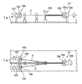
本発明の第1の実施形態にかかる多心撚り合わせ線製造装置について、図1を参照して説明する。本実施形態の多心撚り合わせ線製造装置1は、4本の電線2の一端部をそれぞれ保持し、各電線2を該電線2の軸芯を中心として回転させて各電線2を捻る第1の回転保持部材3と、4つの電線2の他端部を束ねて保持し、4本の電線2を該電線2の捻りを解消する方向に回転させて4本の電線2を撚る第2の回転保持部材4と、を備えている。
First Embodiment A multi-core stranded wire manufacturing apparatus according to a first embodiment of the present invention will be described with reference to FIG. The multi-core stranded wire manufacturing apparatus 1 of the present embodiment holds first ends of four
第1の回転保持部材3は、4本の電線2の一端部をそれぞれ保持する4つの第1保持部材5と、1つの第1の駆動部6と、該第1の駆動部6からの駆動力を4つの第1保持部材5の各々に伝達する1つの回転同期部材7と、を備えている。
The first
4つの第1保持部材5の各々は、円柱状に形成されているとともに、該第1保持部材5の軸方向と平行に切られた複数の歯を有する歯車から構成されている。即ち、各第1保持部材5は、複数の歯を有するギア噛合部51を有している。
Each of the four
また、第1保持部材5には、該第1保持部材5の端面から凹に形成されたチャック部5aが設けられている。各第1保持部材5は、チャック部5a内に1本の電線2の一端部が挿通され、電線2が該電線2の軸芯を中心として回転したり、その軸方向に動かぬように電線2を保持している。即ち、各第1保持部材5は、該第1保持部材5の軸方向と電線2の軸方向とが平行になるように電線2を保持している。4つの第1保持部材5は、回転同期部材7の回転軸周りに設けられている。4つの第1保持部材5は、各々のギア噛合部51が、回転同期部材7のギア部71(後述する)に噛合されている。4つの第1保持部材5の各々は、回転同期部材7が回転することにより、同じ方向に等速度で回転される。
In addition, the first holding
第1の駆動部6は、モータ本体8と、該モータ本体8の出力軸に固定された駆動ギア9と、該駆動ギア9の回転による駆動力を回転同期部材7(後述する)に伝達するベルト10と、を備えている。モータ本体8は駆動ギア9を、所定の回転数で所定の回数、回転させるように予め設定されている。駆動ギア9は、第1保持部材5の軸方向と平行に設けられ、この駆動ギア9には、第1保持部材5の軸方向と平行に切られた複数の歯が形成されている。
The
ベルト10は、第1保持部材5の軸方向と平行に切られた複数の歯が形成された、歯付きベルトである。これら複数の歯は、ベルト10の内周面上に形成されている。このベルト10は、駆動ギア9と回転同期部材7とに掛け渡され、駆動ギア9と回転同期部材7との双方に噛合されている。
The
回転同期部材7は、円柱状に形成されているとともに該回転同期部材7の軸方向と平行に切られた複数の歯を有する歯車から構成されている。即ち、回転同期部材7は、複数の歯を有するギア部71を有している。
The
このような構成の第1の回転保持部材3は、モータ本体8が回転し、このモータ本体8の回転による駆動力が、駆動ギア9、ベルト10を介して、回転同期部材7に伝達され、回転同期部材7を回転させる。回転同期部材7が回転すると、回転同期部材7の回転による駆動力が、回転同期部材7のギア部71に噛合された、4つの第1保持部材5の各ギア噛合部51に伝達され、4つの第1保持部材5を、同じ方向に等速度で回転させる。
In the first
第2の回転保持部材4は、4本の電線2の他端部を束ねて保持する第2保持部材11と、1つの第2の駆動部12と、を備えている。
The second rotation holding member 4 includes a second holding member 11 that holds the other ends of the four
第2保持部材11は、円柱状に形成されているとともに該第2保持部材11の軸方向と平行に切られた複数の歯を有する歯車から構成されている。また、第2保持部材11には、該第2保持部材11の端面から凹に形成された、図示しないチャック部が設けられている。第2保持部材11は、チャック部内に4本の電線2の他端部が束ねられた状態で挿通され、4本の電線2が該電線2の軸芯を中心として回転したり、その軸方向に動かぬように4本の電線2を保持している。即ち、第2保持部材11は、該第2保持部材11の軸方向と電線2の軸方向とが平行になるように電線2を保持している。
The second holding member 11 is formed of a gear having a plurality of teeth formed in a columnar shape and cut in parallel to the axial direction of the second holding member 11. Further, the second holding member 11 is provided with a chuck portion (not shown) that is recessed from the end surface of the second holding member 11. The second holding member 11 is inserted in a state where the other end portions of the four
第2の駆動部12は、モータ本体13と、該モータ本体13の出力軸に固定された駆動ギア14と、該駆動ギア14の回転による駆動力を第2保持部材11に伝達するベルト15と、を備えている。この第2の駆動部12は、前述した第1の駆動部6と同じ構成のため、その詳細な説明を省略する。第2の駆動部12のベルト15は、駆動ギア14と第2保持部材11とに掛け渡され、駆動ギア14と第2保持部材11との双方に噛合されている。
The
続いて、上述した多心撚り合わせ線製造装置1を用いて、多心撚り合わせ線を製造する製造方法について説明する。 Then, the manufacturing method which manufactures a multi-core twisted wire using the multi-core twisted-wire manufacturing apparatus 1 mentioned above is demonstrated.
まず、4本の電線2の一端部をそれぞれ、第1保持部材5のチャック部5a内に挿通し、各第1保持部材5によって各電線2の一端部を保持させる。4本の電線2の他端部を束ねて第2保持部材11のチャック部内に挿通し、第2保持部材11によって4本の電線2の他端部を保持させる。
First, one end portion of each of the four
この状態で、図1(A)に示すように、第1の駆動部6のモータ本体8を駆動して、駆動ギア9を回転させ、駆動ギア9に噛合されたベルト10によって、駆動ギア9の回転による駆動力を回転同期部材7に伝達し、回転同期部材7を回転させる。回転同期部材7が回転すると、回転同期部材7の回転による駆動力が、回転同期部材7のギア部71に噛合された、4つの第1保持部材5の各ギア噛合部51に伝達され、4つの第1保持部材5を、同じ方向に等速度で回転させ、各電線2を捻る(第1工程)。第1の駆動部6のモータ本体8が予め定められた回転数だけ回転すると、モータ本体8の回転を停止して、回転同期部材7及び各第1保持部材5の回転を停止する。この際、各電線2は、捻られたことによる復元力(以下、ストレスと記す)が作用した状態となっている。
In this state, as shown in FIG. 1A, the
このように、回転同期部材7が、第1の駆動部6からの駆動力を4つの第1保持部材5の各々に伝達し、4つの第1保持部材5の各々を回転させるので、多心撚り合わせ線製造装置1は、従来のように、第1保持部材106と同じ数、即ち4つの駆動部107を必要とすることがなくなり、第1の駆動部6の数を、第1保持部材5の数よりも少数にすることができ、第1の駆動部6の数を、第1保持部材5の数よりも少数にできた分、設備を簡素な構成にすることにより、安価でかつ小型化を図ることができる。
As described above, the
また、多心撚り合わせ線製造装置1は、回転同期部材7が第1保持部材5の各々を同じ方向に等速度で回転させるので、4つの第1保持部材5によって保持された4本の電線2のうち一方が、他方に比べて大きく捻られることを防止できる。従って、多心撚り合わせ線が完成した後に、電線2の一方が他方に比べて大きく撚り戻されるという撚り乱れの発生が防止され、撚りピッチが均等に形成された多心撚り合わせ線を製造することができる。これにより、従来の製造装置101のように、移動部材105を用いずとも、撚りピッチが均等に形成された多心撚り合わせ線を製造することができるから、移動部材105を省略できる分、設備を簡素な構成にすることにより、安価でかつ小型化を図った多心撚り合わせ線製造装置1を提供することができる。
Moreover, since the
次に、図1(B)に示すように、第2の駆動部12のモータ本体13を駆動して、駆動ギア14を回転させ、駆動ギア14に噛合されたベルト15によって、駆動ギア14からの駆動力を第2保持部材11に伝達し、第2保持部材11を、前記捻りを解消する方向に回転させ、4本の電線2を撚る(第2工程)。この際、第2保持部材11が前記捻りを解消する方向に回転することにより、4本の電線2が前記捻りを解消する方向に撚られて、各電線2にかかるストレスが吸収される。第2の駆動部12のモータ本体13が、予め定められた回転数だけ、回転すると、モータ本体13の回転を停止し、第2保持部材11の回転を停止する。そして、各電線2は前記ストレスが吸収された(抑制された)状態となり、各電線2において、前記ストレスによって撚り戻りを生じさせることを防止できる。これにより、撚り合わせによるストレスが抑制され、安定したピッチで撚り合わされた多心撚り合わせ線が完成する。
Next, as shown in FIG. 1B, the motor
上述した多心撚り合わせ線製造方法によれば、各電線2を捻る第1工程が行われた後、4本の電線2を、前記捻りを解消する方向に撚る第2工程が行われる。このように、第1工程と第2工程とが別々のタイミングで行われることにより、従来のように、第1保持部材106の回転速度と、第2保持部材108の回転速度と、移動部材105の移動速度と、の同期をとる必要が無くなり、この同期をとるための制御装置がいらなくなるので、制御装置がいらなくなった分、設備を簡素な構成にすることにより、安価でかつ小型化を図った多心撚り合わせ線製造装置1を提供することができる。
According to the multi-core twisted wire manufacturing method described above, after the first step of twisting each
なお、上述した実施形態では、4本の電線2を撚り合わせていたが、本発明はこれに限ったものではなく、多心撚り合わせ線は、2本以上の電線2を撚り合せることで構成されていてもよい。
In the above-described embodiment, the four
また、例えば、撚り合せるための電線2の本数を5本以上に増やす場合においては、電線2を保持するための第1保持部材5を追加し、この第1保持部材5を回転同期部材7に噛合させることにより、多心撚り合わせ線製造装置1の設備を容易に改造することが可能となる。
For example, in the case where the number of the
また、上述した実施形態では、第1の駆動部6がベルト10を備え、ベルト10が、モータ本体8の回転による駆動力を回転同期部材7に伝達しているが、本発明はこれに限ったものではなく、駆動ギア9が回転同期部材7の軸方向と平行となるように、駆動ギア9の先端部が回転同期部材7の軸芯に直接固定され、モータ本体8からの駆動力が回転同期部材7に伝達されていても良い。この場合、第1の駆動部6のベルト10は省略することができる。同様に、駆動ギア14が第2保持部材11の軸方向と平行となるように、駆動ギア14の先端部が第2保持部材11の軸芯に直接固定され、モータ本体13からの駆動力が第2保持部材11に伝達されていても良い。この場合、第2の駆動部12のベルト15は省略することができる。
In the above-described embodiment, the
第2の実施形態
本発明の第2の実施形態にかかる多心撚り合わせ線製造装置1Aについて、図2を参照して説明する。図2において、上述した第1実施形態と同一の構成の部分には、同一符号を付してその詳細な説明を省略する。
Second Embodiment A multi-core stranded
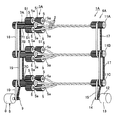
本実施形態の多心撚り合わせ線製造装置1Aは、各4本の電線2が撚り合せされることにより製造された多心撚り合わせ線を3本製造することができる装置である。この多心撚り合わせ線製造装置1Aは、第1の回転保持部材3Aと、第2の回転保持部材4Aと、を備えている。
The multi-core stranded
第1の回転保持部材3Aは、第1の回転保持部材3のうち、4つの第1保持部材5と、該4つの第1保持部材5の各々に噛合された回転同期部材7と、を3組ずつと、3つの回転同期部材7のうち1つを回転させる第1の駆動部6と、該第1の駆動部6からの駆動力を、該第1の駆動部6から離れる方向に隣接された他の回転同期部材7に伝達する第1のベルト16と、を備えている。3つの回転同期部材7は、電線2の径方向に沿って設けられている。
The first
第2の回転保持部材4Aは、第2の回転保持部材4のうち、第2保持部材11を3つと、3つの第2保持部材11のうち1つを回転させる第2の駆動部12と、該第2の駆動部12からの駆動力を、該第2の駆動部12から離れる方向に隣接された他の第2保持部材11に伝達する第2のベルト17と、を備えている。3つの第2保持部材11は、電線2の径方向に沿って設けられている。
4 A of 2nd rotation holding members are the
ここで、説明をわかり易くするために、3つの回転同期部材のうち、図2中の紙面方向の上側に位置する回転同期部材を符号7Aと記し、図2中の紙面方向の下側に位置する回転同期部材を符号7Cと記し、3つの回転同期部材のうち、真ん中に位置する回転同期部材7を符号7Bと記す。また、3つの第2保持部材のうち、図2中の紙面方向の上側に位置し、回転同期部材7Aに対応する第2保持部材を符号11Aと記し、図2中の紙面方向の下側に位置し、回転同期部材7Cに対応する第2保持部材を符号11Cと記し、3つの第2保持部材のうち、真ん中に位置し、回転同期部材7Bに対応する第2保持部材を符号11Bと記す。
Here, in order to make the explanation easy to understand, among the three rotation synchronization members, the rotation synchronization member located on the upper side in the paper surface direction in FIG. 2 is denoted by
第1のベルト16は、第1保持部材5の軸方向と平行に切られた複数の歯が形成された、歯付きベルトである。これら複数の歯は、第1のベルト16の内周面上に形成されている。第1のベルト16は2つ設けられている。1つの第1のベルト16は、回転同期部材7Cと回転同期部材7Bとに掛け渡され、回転同期部材7Cと回転同期部材7Bとの双方に噛合されている。他の第1のベルト16は、回転同期部材7Bと回転同期部材7Aとに掛け渡され、回転同期部材7Bと回転同期部材7Aとの双方に噛合されている。これら2つの第1のベルト16は、特許請求の範囲に記載された「第1の伝達手段」に相当する。
The
第2のベルト17は、第2保持部材11の軸方向と平行に切られた複数の歯が形成された、歯付きベルトである。これら複数の歯は、第2のベルト17の内周面上に形成されている。第2のベルト17は2つ設けられている。1つの第2のベルト17は、第2保持部材11Cと、第2保持部材11Bとに掛け渡され、第2保持部材11Cと第2保持部材11Bとの双方に噛合されている。他の第2のベルト17は、第2保持部材11Bと第2保持部材11Aとに掛け渡され、第2保持部材11Bと第2保持部材11Aとの双方に噛合されている。これら2つの第2のベルト17は、特許請求の範囲に記載された「第2の伝達手段」に相当する。
The
上述した多心撚り合わせ線製造装置1Aを用いることにより、第1の実施形態と同様の方法で、多心撚り合わせ線を3本製造することができる。
By using the multi-core twisted
上述した実施形態によれば、第1の伝達手段としての2つの第1のベルト16が、第1の駆動部6の駆動力を回転同期部材7Cから回転同期部材7B、回転同期部材7Bから回転同期部材7Aへと伝達し、回転同期部材7A、7Bを回転させ、第2の伝達手段としての2つの第2のベルト17が、第2の駆動部12の駆動力を第2保持部材11Cから第2保持部材11B、第2保持部材11Bから11Aへと伝達し、第2保持部材11A、11Bを回転させるので、第1のベルト16、及び第2のベルト17が設けられていることにより、回転同期部材7A,7B、7Cと同じ数、即ち3つの第1の駆動部6及び、第2保持部材11A、11B、11Cと同じ数、即ち3つの第2の駆動部12を設けずとも、3本の多心撚り合わせ線を製造することができ、第1の駆動部6の数を回転同期部材7A,7B、7Cの数よりも少数にした分、及び第2の駆動部12の数を第2保持部材11A、11B、11Cの数よりも少数にした分、設備を簡素な構成にすることにより、安価でかつ小型化を図った多心撚り合わせ線製造装置1Aを提供することができる。
According to the embodiment described above, the two
なお、上述した実施形態では、歯付きベルトであるベルト10は、回転同期部材7Cと駆動ギア9との双方に噛合されているが、本発明はこれに限ったのもではなく、ベルト10、回転同期部材7Cのベルト10が掛け渡される部分、及び駆動ギア9には、複数の歯はなくても良い。即ち、ベルト10は、回転同期部材7Cと駆動ギア9との双方に噛合されていなくても良い。
In the above-described embodiment, the
また、上述した実施形態では、歯付きベルトである第1のベルト16は、回転同期部材7A、7B、7Cに噛合されているが、本発明はこれに限ったのもではなく、第1のベルト16、回転同期部材7A、7B、7Cの第1のベルト16が掛け渡される部分には、複数の歯はなくても良い。即ち、第1のベルト16は、回転同期部材7A、7B、7Cに噛合されていなくても良い。
In the above-described embodiment, the
また、上述した実施形態では、歯付きベルトであるベルト15は、第2保持部材11Cと駆動ギア14との双方に噛合されているが、本発明はこれに限ったのもではなく、ベルト15、第2保持部材11C、及び駆動ギア14には、複数の歯はなくても良い。即ち、ベルト15は、第2保持部材11Cと駆動ギア14との双方に噛合されていなくても良い。第2保持部材11Cは、ベルト15がはめ込まれる溝が形成されたプーリ(滑車)であっても良い。
In the above-described embodiment, the
また、上述した実施形態では、歯付きベルトである第2のベルト17は、第2保持部材11A、11B、11Cに噛合されているが、本発明はこれに限ったのもではなく、第2のベルト17、第2保持部材11A、11B、11Cには、複数の歯はなくても良い。即ち、2のベルト17は、第2保持部材11A、11B、11Cに噛合されていなくても良い。第2保持部材11A、11B、11Cは、第2のベルト17がはめ込まれる溝が形成されたプーリ(滑車)であっても良い。
In the above-described embodiment, the
また、前述した実施形態は本発明の代表的な形態を示したに過ぎず、本発明は、実施形態に限定されるものではない。即ち、本発明の骨子を逸脱しない範囲で種々変形して実施することができる。 Further, the above-described embodiments are merely representative forms of the present invention, and the present invention is not limited to the embodiments. That is, various modifications can be made without departing from the scope of the present invention.
1、1A 多心撚り合わせ線製造装置
2 電線
3、3A 第1の回転保持部材
4、4A 第2の回転保持部材
5 第1保持部材
51 ギア噛合部
6 第1の駆動部
7、7A、7B,7C 回転同期部材
71 ギア部
11、11A、11B,11C 第2保持部材
12 第2の駆動部
16 第1のベルト(第1の伝達手段)
17 第2のベルト(第2の伝達手段)
DESCRIPTION OF
17 Second belt (second transmission means)
Claims (4)
前記複数の電線の他端部を束ねて保持して回転する第2の回転保持部材と、を備え、
前記第1の回転保持部材は、前記複数の電線の一端部をそれぞれ保持する複数の第1保持部材と、
該複数の第1保持部材を回転させる第1の駆動部と、
該第1の駆動部からの駆動力を前記複数の第1保持部材の各々に伝達し、前記複数の第1保持部材の各々を同じ方向に等速度で回転させる回転同期部材と、を備え、
前記第2の回転保持部材の回転が停止した状態で、前記複数の第1保持部材が、前記第1の駆動部により前記電線の軸芯を中心とした方向に所定の回転数だけ回転されて前記各電線を捻じった後、前記第2の回転保持部材が、前記各第1保持部材と同じ方向に回転されて前記各電線の捻りを解消しつつ前記電線を撚ることを特徴とする多心撚り合わせ線製造装置。 A first rotary holding member for holding one end of the plurality of electric wires respectively,
A second rotation holding member that rotates by bundling and holding the other ends of the plurality of electric wires,
The first rotation holding member includes a plurality of first holding members that respectively hold one end portions of the plurality of electric wires;
A first drive unit that rotates the plurality of first holding members;
A rotation synchronization member that transmits a driving force from the first driving unit to each of the plurality of first holding members, and rotates each of the plurality of first holding members in the same direction at a constant speed;
In a state where the rotation of the second rotation holding member is stopped, the plurality of first holding members are rotated by a predetermined number of rotations in a direction around the axis of the electric wire by the first drive unit. After twisting each electric wire, the second rotation holding member is rotated in the same direction as each first holding member to twist the electric wire while eliminating the twist of each electric wire. Multi-core twisted wire manufacturing equipment.
前記複数の電線の他端部を束ねて保持し、前記複数の電線を該電線の捻りを解消する方向に回転させて前記複数の電線を撚る第2の回転保持部材と、を備え、
前記第1の回転保持部材は、前記複数の電線の一端部をそれぞれ保持する複数の第1保持部材と、
該複数の第1保持部材を回転させる第1の駆動部と、
該第1の駆動部からの駆動力を前記複数の第1保持部材の各々に伝達し、前記複数の第1保持部材の各々を同じ方向に等速度で回転させる回転同期部材と、を備え、
前記回転同期部材が複数設けられ、
前記複数の回転同期部材のうち一つには、前記第1の駆動部から駆動力が伝達され、
前記駆動力を、前記第1の駆動部から他の回転同期部材に伝達する第1の伝達手段を有し、
前記第2の回転保持部材は、前記複数の電線の他端部を束ねて保持する複数の第2保持部材と、該複数の第2保持部材を回転させる第2の駆動部と、前記複数の第2保持部材のうち一つに伝達された前記第2の駆動部からの駆動力を、前記第2の駆動部から他の第2保持部材に伝達する第2の伝達手段と、を有したことを特徴とする多心撚り合わせ線製造装置。 A first rotation holding member that holds one end of each of the plurality of electric wires, and rotates each of the plurality of electric wires around the axis of the electric wire to twist each electric wire;
A second rotation holding member that bundles and holds the other end portions of the plurality of electric wires, and rotates the plurality of electric wires in a direction to eliminate twisting of the electric wires to twist the plurality of electric wires,
The first rotation holding member includes a plurality of first holding members that respectively hold one end portions of the plurality of electric wires;
A first drive unit that rotates the plurality of first holding members;
A rotation synchronization member that transmits a driving force from the first driving unit to each of the plurality of first holding members, and rotates each of the plurality of first holding members in the same direction at a constant speed;
A plurality of the rotation synchronization members are provided,
A driving force is transmitted from one of the plurality of rotation synchronization members to the first driving unit,
A first transmission means for transmitting the driving force from the first driving unit to another rotation synchronization member;
The second rotation holding member includes a plurality of second holding members that bundle and hold the other ends of the plurality of electric wires, a second driving unit that rotates the plurality of second holding members, and the plurality of the plurality of electric wires. And second transmission means for transmitting the driving force from the second driving unit transmitted to one of the second holding members to the other second holding member from the second driving unit. A multi-core stranded wire manufacturing apparatus characterized by that.
前記複数の第1保持部材の各々は、前記ギア部に噛合するギア噛合部を有し、
前記複数の第1保持部材は、前記回転同期部材の回転軸周りに設けられていることを特徴とする請求項1又は請求項2記載の多心撚り合わせ線製造装置。 The rotation synchronization member is configured to have a gear portion,
Each of the plurality of first holding members has a gear meshing portion that meshes with the gear portion,
The multi-core stranded wire manufacturing apparatus according to claim 1 or 2, wherein the plurality of first holding members are provided around a rotation axis of the rotation synchronization member.
芯を中心とした同じ方向に等速度で所定の回転数だけ回転させ、前記各電線を捻る第1工程と、
前記複数の電線の他端部を束ねた状態で前記電線の捻りを解消する方向に回転させ、前記複数の電線を撚る第2工程と、を備え、
前記第1工程を行った後、前記第2工程を行うことを特徴とした多心撚り合わせ線製造方法。 While holding both ends of the plurality of electric wires, each of the one end portions of the plurality of electric wires is rotated by a predetermined number of rotations at a constant speed in the same direction around the axis of the electric wire, and the electric wires are twisted. The first step;
A second step of twisting the plurality of electric wires by rotating in a direction to cancel the twist of the electric wires in a state where the other ends of the plurality of electric wires are bundled,
After the said 1st process is performed, the said 2nd process is performed, The multi-core twisted-wire manufacturing method characterized by the above-mentioned.
Priority Applications (1)
| Application Number | Priority Date | Filing Date | Title |
|---|---|---|---|
| JP2011275431A JP5888552B2 (en) | 2011-12-16 | 2011-12-16 | Multi-core stranded wire manufacturing apparatus and multi-core stranded wire manufacturing method |
Applications Claiming Priority (1)
| Application Number | Priority Date | Filing Date | Title |
|---|---|---|---|
| JP2011275431A JP5888552B2 (en) | 2011-12-16 | 2011-12-16 | Multi-core stranded wire manufacturing apparatus and multi-core stranded wire manufacturing method |
Publications (2)
| Publication Number | Publication Date |
|---|---|
| JP2013125727A JP2013125727A (en) | 2013-06-24 |
| JP5888552B2 true JP5888552B2 (en) | 2016-03-22 |
Family
ID=48776852
Family Applications (1)
| Application Number | Title | Priority Date | Filing Date |
|---|---|---|---|
| JP2011275431A Active JP5888552B2 (en) | 2011-12-16 | 2011-12-16 | Multi-core stranded wire manufacturing apparatus and multi-core stranded wire manufacturing method |
Country Status (1)
| Country | Link |
|---|---|
| JP (1) | JP5888552B2 (en) |
Families Citing this family (4)
| Publication number | Priority date | Publication date | Assignee | Title |
|---|---|---|---|---|
| JP2017045627A (en) * | 2015-08-27 | 2017-03-02 | 住友電装株式会社 | Twisted wire manufacturing apparatus and twisted wire manufacturing method |
| JP2017045628A (en) * | 2015-08-27 | 2017-03-02 | 住友電装株式会社 | Twisted wire manufacturing apparatus and twisted wire manufacturing method |
| CN106019660A (en) * | 2016-08-11 | 2016-10-12 | 京东方科技集团股份有限公司 | Metal wire twisting device |
| EP3349222A1 (en) * | 2017-01-13 | 2018-07-18 | Schleuniger Holding AG | Gripper jaw and line gripper for a pair of electrical or optical lines |
Family Cites Families (2)
| Publication number | Priority date | Publication date | Assignee | Title |
|---|---|---|---|---|
| JP4066753B2 (en) * | 2002-09-12 | 2008-03-26 | 住友電装株式会社 | Wire twisting device |
| JP5181895B2 (en) * | 2008-07-23 | 2013-04-10 | 住友電装株式会社 | Twisted wire manufacturing device, twisted wire manufacturing method, and twisted wire |
-
2011
- 2011-12-16 JP JP2011275431A patent/JP5888552B2/en active Active
Also Published As
| Publication number | Publication date |
|---|---|
| JP2013125727A (en) | 2013-06-24 |
Similar Documents
| Publication | Publication Date | Title |
|---|---|---|
| US9692283B2 (en) | Apparatus and method for forming coil members | |
| EP2849319B1 (en) | Manufacturing method for rotating electric machine | |
| JP5888552B2 (en) | Multi-core stranded wire manufacturing apparatus and multi-core stranded wire manufacturing method | |
| JP4884024B2 (en) | Twisted wire manufacturing method and manufacturing apparatus | |
| JP5848093B2 (en) | Metal wire connecting method and connecting device | |
| JP5936270B2 (en) | Winding device and winding method | |
| CN106415739B (en) | Twisted wire manufacture device and twisted wire manufacture method | |
| US20180331605A1 (en) | Coil forming device and coil forming method | |
| JP2012151996A (en) | Method for annularly arranging coil segment, device for annularly arranging coil segment and stator | |
| JP5420463B2 (en) | Stator coil manufacturing apparatus and manufacturing method | |
| JP5833954B2 (en) | Twisted wire manufacturing apparatus and twisted wire manufacturing method | |
| CN106463214A (en) | Stranded wire manufacturing device and twisted wire manufacturing method | |
| JP6259519B2 (en) | Twist wire manufacturing apparatus and twist wire manufacturing method | |
| JP2009183951A (en) | Connection method of metal wire body and connection device used for the same | |
| JP5875150B2 (en) | Twisted wire manufacturing apparatus and twisted wire manufacturing method | |
| JP5064700B2 (en) | Twisted wire manufacturing method and manufacturing apparatus | |
| JP2009013519A (en) | Twisting machine and method for producing strand wire by using the same | |
| JP6678049B2 (en) | Wire twisting device | |
| JP6678048B2 (en) | Wire twisting device | |
| JP2015001237A (en) | Drive device | |
| JP2020096026A (en) | Coil forming method and coil forming apparatus | |
| WO2017033721A1 (en) | Device for producing stranded electrical wire and method for producing stranded electrical wire | |
| JP2017045628A (en) | Twisted wire manufacturing apparatus and twisted wire manufacturing method |
Legal Events
| Date | Code | Title | Description |
|---|---|---|---|
| A621 | Written request for application examination |
Free format text: JAPANESE INTERMEDIATE CODE: A621 Effective date: 20141119 |
|
| A977 | Report on retrieval |
Free format text: JAPANESE INTERMEDIATE CODE: A971007 Effective date: 20150729 |
|
| A131 | Notification of reasons for refusal |
Free format text: JAPANESE INTERMEDIATE CODE: A131 Effective date: 20150825 |
|
| A521 | Request for written amendment filed |
Free format text: JAPANESE INTERMEDIATE CODE: A523 Effective date: 20150928 |
|
| TRDD | Decision of grant or rejection written | ||
| A01 | Written decision to grant a patent or to grant a registration (utility model) |
Free format text: JAPANESE INTERMEDIATE CODE: A01 Effective date: 20160126 |
|
| A61 | First payment of annual fees (during grant procedure) |
Free format text: JAPANESE INTERMEDIATE CODE: A61 Effective date: 20160203 |
|
| R150 | Certificate of patent or registration of utility model |
Ref document number: 5888552 Country of ref document: JP Free format text: JAPANESE INTERMEDIATE CODE: R150 |
|
| R250 | Receipt of annual fees |
Free format text: JAPANESE INTERMEDIATE CODE: R250 |
|
| R250 | Receipt of annual fees |
Free format text: JAPANESE INTERMEDIATE CODE: R250 |
|
| R250 | Receipt of annual fees |
Free format text: JAPANESE INTERMEDIATE CODE: R250 |
|
| R250 | Receipt of annual fees |
Free format text: JAPANESE INTERMEDIATE CODE: R250 |
|
| R250 | Receipt of annual fees |
Free format text: JAPANESE INTERMEDIATE CODE: R250 |
|
| S531 | Written request for registration of change of domicile |
Free format text: JAPANESE INTERMEDIATE CODE: R313531 |
|
| R350 | Written notification of registration of transfer |
Free format text: JAPANESE INTERMEDIATE CODE: R350 |
|
| R250 | Receipt of annual fees |
Free format text: JAPANESE INTERMEDIATE CODE: R250 |
|
| R250 | Receipt of annual fees |
Free format text: JAPANESE INTERMEDIATE CODE: R250 |
|
| R250 | Receipt of annual fees |
Free format text: JAPANESE INTERMEDIATE CODE: R250 |