JP5888198B2 - Sapphire single crystal manufacturing equipment - Google Patents
Sapphire single crystal manufacturing equipment Download PDFInfo
- Publication number
- JP5888198B2 JP5888198B2 JP2012213141A JP2012213141A JP5888198B2 JP 5888198 B2 JP5888198 B2 JP 5888198B2 JP 2012213141 A JP2012213141 A JP 2012213141A JP 2012213141 A JP2012213141 A JP 2012213141A JP 5888198 B2 JP5888198 B2 JP 5888198B2
- Authority
- JP
- Japan
- Prior art keywords
- single crystal
- raw material
- crucible
- sapphire single
- material melt
- Prior art date
- Legal status (The legal status is an assumption and is not a legal conclusion. Google has not performed a legal analysis and makes no representation as to the accuracy of the status listed.)
- Expired - Fee Related
Links
Images

Landscapes
- Crystals, And After-Treatments Of Crystals (AREA)
Description
本発明は、チョクラルスキー法によるサファイア単結晶の製造装置に関する。 The present invention relates to an apparatus for producing a sapphire single crystal by the Czochralski method.
サファイア単結晶は、酸化アルミニウムのコランダム構造を有する結晶体であり、優れた機械的および熱的特性、化学的安定性、光透過性を有することから、多くの分野ですでに利用されている。特に、サファイア単結晶は、半導体分野において、窒化ガリウム(GaN)系発光ダイオードの発光層を成長させるための基板として、あるいは、シリコン・オン・サファイア(SOS)デバイス用の基板などに用いられており、これらの用途の重要性が高まるに応じて、その需要が飛躍的に伸びてきている。 A sapphire single crystal is a crystal having a corundum structure of aluminum oxide, and has already been used in many fields because it has excellent mechanical and thermal properties, chemical stability, and light transmittance. In particular, sapphire single crystals are used in the semiconductor field as a substrate for growing a light emitting layer of a gallium nitride (GaN) light emitting diode or as a substrate for a silicon-on-sapphire (SOS) device. As the importance of these applications increases, the demand for them has increased dramatically.
サファイア単結晶を製造する主な方法として、サファイア原料を坩堝内で融解し、その原料融液表面に種結晶を接触させて徐々に引き上げることにより単結晶を育成するチョクラルスキー法(Cz法)やカイロポーラス法(Kyropulous法)などが知られている。なお、育成されたサファイア単結晶は、基板状に加工され、表面を研磨することによりサファイア基板とされる。 Czochralski method (Cz method) in which a sapphire single crystal is produced by melting a sapphire raw material in a crucible and bringing the seed crystal into contact with the surface of the raw material melt and gradually pulling it up. The Kyropulous method is also known. The grown sapphire single crystal is processed into a substrate shape, and the surface is polished to form a sapphire substrate.
サファイア原料融液からチョクラルスキー法によりサファイア単結晶を製造するには、図4に示すようなサファイア単結晶育成装置が用いられる(たとえば、特開2011−195423号公報参照)。このサファイア単結晶育成装置は、炉体7により形成されるチャンバ内に、サファイア原料が充填されるモリブデン製またはタングステン製の坩堝1と、坩堝1の外周面を加熱するカーボン製の円筒状ヒータ3と、坩堝1の底面を加熱するカーボン製の円盤状ヒータ4と、断熱空間15を構成するためのカーボン製の断熱材6とを備える。また、断熱材6の底面部16に設けられた開口に嵌入された酸化アルミニウム製の絶縁筒8を介して、断熱空間15の外側から内側に延在し、円筒状ヒータ3および円盤状ヒータ4のそれぞれに接続され、電力を供給するための2つの円筒状ヒータ電極5a、5bと、断熱材6の底面部16と円盤状ヒータ4の開口を貫通して、坩堝1を支持する支持軸2が設けられている。さらに、断熱材6の上面部17に設けられた開口を通じて、ホルダ9aを介して、先端に種結晶11が取り付けられた引き上げ軸9が挿入され、育成時に、坩堝1内の原料融液10からチョクラルスキー法によりサファイア単結晶12を育成できるようになっている。
In order to manufacture a sapphire single crystal from a sapphire raw material melt by the Czochralski method, a sapphire single crystal growing apparatus as shown in FIG. 4 is used (for example, refer to Japanese Patent Application Laid-Open No. 2011-195423). This sapphire single crystal growing apparatus includes a crucible 1 made of molybdenum or tungsten filled with a sapphire raw material in a chamber formed by a
ところで、融点が2040℃という2000℃を超える高い融点を有するサファイア単結晶をチョクラルスキー法により育成する場合、断熱空間15内は、当然のごとく2000℃を超える高温環境となる。したがって、サファイア単結晶の育成においては、断熱空間15内の熱伝達は輻射が主体となること、および、タンタル酸リチウム(LT)、ニオブ酸リチウム(LN)、または、イットリウム・アルミニウム・ガーネット(YAG)などの他の酸化物単結晶の融液と比較して、原料融液の粘度が非常に高く、対流が不安定であることに起因して、融液内の温度勾配の適正化が困難なものとなっている。また、LT、LNまたはYAGなどの酸化物単結晶の育成では、成長界面が、融液表面と略平行の状態を維持したまま、該融液表面に対して垂直方向下向きとなる方向に成長していくが、サファイア単結晶の育成においては、成長界面が、融液表面に対して大きな角度をもって、該融液表面に対して、ほぼ水平方向に成長していくという特性を有している。このため、融液内の温度勾配が不適切である場合、成長界面の形状、特に、その先端部が下凹となりやすい。成長界面の形状が下凹となると、育成結晶中に気泡、リネージなどのマクロな結晶欠陥を生じ、さらには、リネージが集積することにより多結晶となり、サファイア単結晶が得られなくなる場合がある。
By the way, when a sapphire single crystal having a melting point of 2040 ° C., which is higher than 2000 ° C., is grown by the Czochralski method, the
このような観点から、原料融液10の内部および表面近傍の垂直方向および水平方向の温度勾配が適正となるように制御する必要がある。従来、サファイア単結晶の結晶育成においては、原料融液の温度勾配を制御する1つの方法として、炉体内の雰囲気ガスであるArガスの対流(以下、「Arガス流」という)を利用することが行われている。すなわち、炉体7の坩堝1の外周部の上方には、ステー(支持部材)14を介してヒータシールド13が設置され、坩堝1の周囲を上昇する高温のArガス流を原料融液の表面に向かわせることにより、融液表面近傍の水平方向の温度勾配を、坩堝1の側壁付近が高温となり、中心付近が低温となるように制御している。
From such a viewpoint, it is necessary to control the temperature gradient in the vertical and horizontal directions inside and near the surface of the
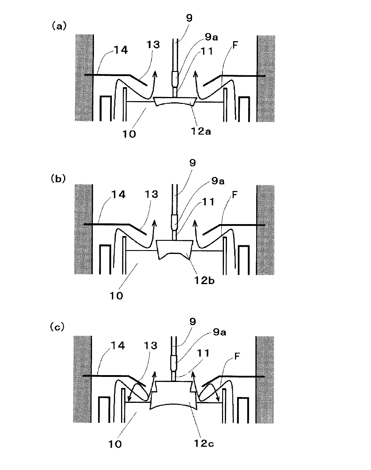
しかしながら、このような温度勾配の制御を行っても、得られるサファイア単結晶12aでは、特に、結晶の上半部において、気泡が取り込まれ、リネージが発生し、このリネージの集積によって多結晶化するなどの不具合が生じており、良品が得られるのが実質的に結晶の下半部に制限され、サファイア単結晶の収率を十分に向上できていないのが実情である。
However, even if such temperature gradient control is performed, in the sapphire
また、サファイア単結晶の育成における2000℃を超える高温環境下では、カーボン製の各ヒータ3、4やカーボン製の断熱材6からカーボンの昇華が起こる。このカーボン昇華により生じたカーボンガスは、ヒータで加熱され、高温となったArガス流とともに、断熱空間15内を対流し、原料融液と接触して、原料融液を還元する。これにより生成したアルミニウムやアルミニウム酸化物が坩堝1の材料と反応し、坩堝材が不純物として融液中に取り込まれ、それらがサファイア単結晶に混入し、その品質を低下させるという問題もある(特開2011-195423号公報参照)。
Further, in a high temperature environment exceeding 2000 ° C. in growing a sapphire single crystal, carbon sublimation occurs from the
温度勾配の制御、汚染などの問題を解決するための手段として、シリコン単結晶の育成におけるものであるが、坩堝の上端部に熱遮蔽板および熱反射板を設置することが提案されている(特開平5−294783号公報参照)。この技術では、坩堝の上縁に円筒状の熱遮蔽壁を設置して、原料融液からの輻射を制御するとともにArガス流の影響を排除している。しかしながら、この技術は、結晶の保温性を高め、結晶内の温度勾配を緩和するものであるため、この技術を、原料融液内の垂直方向および水平方向の温度勾配を十分に大きくする必要があるサファイア単結晶の育成に適用することはできない。 As a means for solving problems such as temperature gradient control and contamination, it is proposed to grow a silicon single crystal, and it has been proposed to install a heat shielding plate and a heat reflecting plate at the upper end of the crucible ( Japanese Patent Laid-Open No. 5-29483). In this technique, a cylindrical heat shield wall is installed at the upper edge of the crucible to control radiation from the raw material melt and eliminate the influence of Ar gas flow. However, since this technique increases the heat retention of the crystal and relaxes the temperature gradient in the crystal, it is necessary to sufficiently increase the temperature gradient in the vertical and horizontal directions in the raw material melt. It cannot be applied to the growth of a certain sapphire single crystal.
本発明は、上述のような問題に鑑み、チョクラルスキー法によるサファイア単結晶の結晶育成において、結晶欠陥のないサファイア単結晶を収率よく提供することを目的とする。 In view of the above-described problems, an object of the present invention is to provide a sapphire single crystal free of crystal defects in a high yield in crystal growth of a sapphire single crystal by the Czochralski method.
本発明のサファイア単結晶育成装置は、チョクラルスキー法によるサファイア単結晶の製造装置であって、炉体内に断熱空間を形成するカーボン製断熱材と、該断熱空間内に配置され原料融液を収容する坩堝と、該坩堝を前記断熱空間内に支持する支持軸と、前記断熱空間内まで伸長し、前記坩堝の上方に育成したサファイア単結晶を引き上げる引き上げ軸と、前記断熱空間内に配置され、前記坩堝の周囲に配置されるカーボン製ヒータを備える。 The sapphire single crystal growth apparatus of the present invention is a sapphire single crystal manufacturing apparatus using the Czochralski method, and a carbon heat insulating material that forms a heat insulating space in a furnace body, and a raw material melt disposed in the heat insulating space. A crucible to be accommodated, a support shaft for supporting the crucible in the heat insulation space, a pulling shaft for extending the sapphire single crystal grown above the crucible, and disposed in the heat insulation space. And a carbon heater disposed around the crucible.
特に、本発明のサファイア単結晶育成装置は、従来技術で設けられていた前記坩堝の外周部の上方で、該坩堝の外周部と前記断熱材の内周面との間に配置され、下方からのガス流を前記坩堝内の前記原料融液に向けて転向させるヒータシールドなどの障害物は設置されていない。 In particular, the sapphire single crystal growth apparatus of the present invention is disposed between the outer peripheral portion of the crucible and the inner peripheral surface of the heat insulating material above the outer peripheral portion of the crucible provided in the prior art, and from below. There is no obstacle such as a heater shield that turns the gas flow toward the raw material melt in the crucible.
その代わりに、坩堝の上方に配置され、前記原料融液および断熱空間の垂直方向の温度勾配を制御する手段と、前記坩堝の上端縁に設置され、前記下方からのガス流と、前記原料融液および育成中のサファイア単結晶の肩部側面との接触を防止する手段とを備える。 Instead, it is disposed above the crucible, and is disposed at the upper edge of the crucible, and is disposed at the upper edge of the crucible. And means for preventing contact between the liquid and the shoulder side surface of the growing sapphire single crystal.
前記断熱材と、前記坩堝と、前記原料融液および断熱空間の垂直方向の温度勾配を制御する手段とにより、前記断熱材の内周面に沿って、断熱空間の底面から上面まで略円筒状の前記下方からのガス流の流路が形成されることが好ましい。 A substantially cylindrical shape from the bottom surface to the top surface of the heat insulating space along the inner peripheral surface of the heat insulating material by the heat insulating material, the crucible, and means for controlling the temperature gradient in the vertical direction of the raw material melt and the heat insulating space. It is preferable that a gas flow path from below is formed.
前記原料融液および断熱空間の垂直方向の温度勾配を制御する手段が、原料融液からの輻射熱を反射する、少なくとも1枚以上の円輪状の熱反射板であることが好ましい。なお、この熱反射板は、水平方向の温度勾配を制御する手段としても機能する。 It is preferable that the means for controlling the temperature gradient in the vertical direction of the raw material melt and the heat insulating space is at least one annular heat reflecting plate that reflects radiant heat from the raw material melt. This heat reflecting plate also functions as a means for controlling the temperature gradient in the horizontal direction.
前記下方からのガス流と、前記原料融液および育成中のサファイア単結晶の肩部側面との接触を防止する手段が、前記坩堝上端縁から径方向内方に伸長するリッドであることが好ましい。さらに、このリッドの上面に該リッドから上方へ伸長する円筒状の突起部が設けられていることがより好ましい。 It is preferable that the means for preventing the gas flow from the lower side and the raw material melt and the shoulder side surface of the growing sapphire single crystal to extend radially inward from the upper edge of the crucible. . Furthermore, it is more preferable that a cylindrical protrusion that extends upward from the lid is provided on the upper surface of the lid.
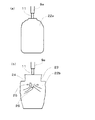
本発明の製造装置を使用して得られるサファイア単結晶は、クビレや二段肩のない、肩部の形状がなだらかであることを特徴とする。また、本発明の製造装置を使用して得られるサファイア単結晶は、上半部における結晶欠陥やリネージ不良、さらには、不純物の混入の発生がいずれも防止される。したがって、サファイア単結晶の下半部のみならず、サファイア単結晶の上半部まで良品の採取が可能となるため、本発明は、サファイア単結晶を収率よく製造することを可能とするものであり、その工業的意義はきわめて大きい。 The sapphire single crystal obtained by using the production apparatus of the present invention is characterized in that the shape of the shoulder portion is gentle and has no neck or double shoulder. Moreover, the sapphire single crystal obtained by using the manufacturing apparatus of the present invention can prevent any crystal defects and lineage defects in the upper half, and further contamination of impurities. Therefore, since it is possible to collect not only the lower half of the sapphire single crystal but also the upper half of the sapphire single crystal, the present invention makes it possible to produce the sapphire single crystal with high yield. Yes, its industrial significance is extremely great.
本発明者らは、上述の問題に鑑みて、坩堝1の外周部の上方にヒータシールド13を設置した構造について鋭意検討を行った。その結果、従来の円筒状ヒータ3および円盤状ヒータ4で加熱されたガスを融液の表面外周部に当てる、ガス対流制御による融液上方の温度勾配の制御では、融液表面の水平方向の温度勾配はある程度大きくすることはできるが、融液表面の垂直方向の温度勾配を大きくすることについては十分でないとの知見が得られた。
In view of the above-mentioned problems, the present inventors diligently studied a structure in which the
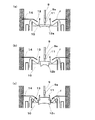
このため、結晶育成の初期段階で急速に結晶径が拡大し、平板状結晶が形成されやすくなる。このような形状の単結晶が形成された場合、引き上げ軸方向から放熱される固化潜熱量よりも、融液表面から露出した肩部より直接的に放熱される固化潜熱量が増大し、固液界面が結晶側に凹んだ凹界面となってしまう(図5(a)参照)。この凹界面に沿って、気泡が界面に滞留し、単結晶内に取り込まれることとなる。 For this reason, the crystal diameter rapidly expands at the initial stage of crystal growth, and a flat crystal is easily formed. When a single crystal having such a shape is formed, the amount of solidification latent heat radiated directly from the shoulder exposed from the melt surface is larger than the amount of solidification latent heat radiated from the pulling-up axis direction. The interface becomes a concave interface that is recessed toward the crystal side (see FIG. 5A). Along this concave interface, bubbles stay at the interface and are taken into the single crystal.
また、この状態のまま、サファイア単結晶12aの成長が進行すると、ヒータの近傍を通過して上昇する高温のArガスが、ヒータシールド13の作用により、結晶肩部側面に当たるようになるため、サファイア単結晶の結晶径が縮小することになる(クビレの発生、図5(b)参照)。さらに、サファイア単結晶12bの成長が進行すると、サファイア単結晶の引き上げに伴い、結晶肩部が、垂直方向の温度勾配が大きいヒータシールド13上方の空間に位置するようになるので、サファイア単結晶上部からの放射熱が大きくなり、結晶径が急激に拡大する現象が起こりやすくなる(二段肩の発生、図5(c)参照)。
Further, if the growth of the sapphire
このような二段肩が発生すると、育成されるサファイア単結晶12cは異方成長しやすくなり、引き上げ軸に対して大きく対称性がくずれた形状となる。これは、ヒータシールド13とサファイア単結晶12の肩部で原料融液が蓋をされた状態となるために融液表面に流れ込んできたArガスの流れが安定せず、サファイア単結晶12cの外周付近の温度分布が軸対称から外れるためと考えられる。このように形状の軸対称性が悪化した結晶では、結晶欠陥が発生しやすく、サファイア単結晶の収率を低下させる大きな原因となっている。
When such a two-step shoulder is generated, the sapphire
そこで、本発明者らは、Arガス流による温度勾配の制御に代替する手段を鋭意検討し、本発明に至ったものである。本発明では、Arガス流によらずに温度勾配を形成するため、図4のヒータシールド13に代えて、熱反射板により原料融液の温度勾配を形成する。具体的には、炉体の天井から下方に伸長する支柱を介して、少なくとも1枚以上の円輪状の熱反射板を設置する。
Therefore, the present inventors have intensively studied a means to replace the temperature gradient control by Ar gas flow, and have arrived at the present invention. In the present invention, in order to form a temperature gradient irrespective of the Ar gas flow, the temperature gradient of the raw material melt is formed by a heat reflecting plate instead of the
この結果、本発明の装置では、炉体の内壁と支柱との間に、高温に熱せられたArガスが上方の断熱空間に流通することを可能とする略円筒状の空間を確保することができ、これにより、Arガスがヒータシールド、または、熱反射板もしくは熱遮蔽板と原料融液の間に滞留することを防止することができる。さらに、カーボン蒸気を含んだArガスが原料融液に直接衝突して、カーボン蒸気と原料融液が反応することに起因する、不純物の混入が防止される。 As a result, in the apparatus of the present invention, it is possible to secure a substantially cylindrical space that allows Ar gas heated to a high temperature to flow through the upper heat insulating space between the inner wall of the furnace body and the support column. Thus, Ar gas can be prevented from staying between the heater shield or the heat reflecting plate or the heat shielding plate and the raw material melt. Furthermore, Ar gas containing carbon vapor directly collides with the raw material melt, thereby preventing impurities from being mixed due to the reaction between the carbon vapor and the raw material melt.
一方、温度勾配の制御を熱反射板により行うことにより、反射される輻射熱の進行方向を一定方向に制御することができるため、サファイア単結晶の育成における2000℃を超えるような高温環境下においても、原料融液内および表面、さらには断熱空間の温度勾配を高精度かつ容易に制御することができる。このように温度勾配を適正化することにより、引き上げ軸方向の放熱量を制御でき、かつ、サファイア単結晶の径方向の急速な成長を抑止することができるため、クビレや二段肩の発生を効果的に防止することが可能となる。 On the other hand, by controlling the temperature gradient with the heat reflector, the traveling direction of the reflected radiant heat can be controlled in a certain direction, so even under a high temperature environment exceeding 2000 ° C. in the growth of sapphire single crystals. In addition, the temperature gradient in the raw material melt and on the surface, and also in the heat insulating space can be controlled with high accuracy and ease. By optimizing the temperature gradient in this way, the amount of heat released in the pulling axis direction can be controlled, and rapid growth in the radial direction of the sapphire single crystal can be suppressed. It can be effectively prevented.
さらに、本発明の装置では、カーボン蒸気を含んだArガスと原料融液とが直接接触することを防止するため、坩堝1の上端部に、円輪状のリッド(蓋)を設置することにより、不純物の混入をほぼ完全に防止している。 Furthermore, in the apparatus of the present invention, in order to prevent Ar gas containing carbon vapor from directly contacting the raw material melt, by installing an annular lid (lid) on the upper end of the crucible 1, Impurities are almost completely prevented.
本発明は、このような構造上の特徴により、サファイア単結晶の上半部から下半部まで、結晶欠陥、リネージ不良、不純物の混入といった不具合を除去することができ、育成されたサファイア単結晶の大半から良品を得ることを可能としている。 The present invention can eliminate defects such as crystal defects, lineage defects, and impurity contamination from the upper half to the lower half of the sapphire single crystal due to such structural features. It is possible to obtain good products from the majority of people.
以下、(1)本発明のサファイア単結晶の製造装置、および、(2)本発明により得られるサファイア単結晶インゴットについて、さらに詳細に説明する。 Hereinafter, (1) the sapphire single crystal manufacturing apparatus of the present invention and (2) the sapphire single crystal ingot obtained by the present invention will be described in more detail.
(1)サファイア単結晶の製造装置
本発明は、チョクラルスキー法によるサファイア単結晶の製造装置に関し、本発明の製造装置は、従来のチョクラルスキー法によるサファイア単結晶の製造装置と同様の基本構造を備える。特に、坩堝の上方に配置され、原料融液および断熱空間の垂直方向の温度勾配を制御する手段(以下、「垂直方向温度勾配制御手段」という)と、坩堝の上端縁に設置され、下方からのガス流と、前記原料融液および育成中のサファイア単結晶の肩部側面との接触を防止する手段(以下、「接触防止手段」という)とを備えることを特徴とする。
(1) Sapphire single crystal manufacturing apparatus TECHNICAL FIELD This invention relates to the sapphire single crystal manufacturing apparatus by the Czochralski method, and the manufacturing apparatus of this invention is the same basic as the sapphire single crystal manufacturing apparatus by the conventional Czochralski method. Provide structure. In particular, it is disposed above the crucible, and controls the temperature gradient in the vertical direction of the raw material melt and the heat insulation space (hereinafter referred to as “vertical temperature gradient control means”), and is installed at the upper edge of the crucible from below. And means for preventing contact between the raw material melt and the shoulder side surface of the growing sapphire single crystal (hereinafter referred to as “contact prevention means”).
これらの手段を備えることにより、原料融液および断熱空間の垂直方向の温度勾配を適正に制御するとともに、Arガスと、原料融液およびサファイア単結晶との接触を防止することができるため、得られるサファイア単結晶にクビレや二段肩が発生することを効果的に防止することができるとともに、不純物の混入も抑制することができる。 By providing these means, it is possible to appropriately control the temperature gradient in the vertical direction of the raw material melt and the heat insulating space, and to prevent the Ar gas from contacting the raw material melt and the sapphire single crystal. As a result, it is possible to effectively prevent the occurrence of constrictions and double shoulders in the sapphire single crystal, and to suppress the mixing of impurities.
また、前記原料融液の径方向の温度勾配を制御する手段(以下、「径方向温度制御手段」という)をさらに備えることで、結晶育成の初期段階から、サファイア単結晶の成長界面の形状を下凸に維持することができるため、さらに高品質のサファイア単結晶を得ることが可能となる。 Further, by further providing means for controlling the temperature gradient in the radial direction of the raw material melt (hereinafter referred to as “radial temperature control means”), the shape of the growth interface of the sapphire single crystal can be changed from the initial stage of crystal growth. Since it can be maintained downwardly convex, it is possible to obtain a higher quality sapphire single crystal.
これらの手段の設計は、予めコンピュータによるシミュレーションに基づいて行うか、および/または、予備試験を行い、各ヒータの出力およびその比率、ヒータと坩堝の相対位置などと温度勾配の関係を、所定の放射型温度計や熱電対を用いて測定し、これによって得られたデータに基づいて行うことが好ましい。また、上記予備試験において、結晶肩部のみの育成を行い、温度勾配と単結晶の成長界面の形状も把握しておくことがより好ましい。 The design of these means is performed based on computer simulation in advance and / or a preliminary test, and the relationship between the output of each heater and its ratio, the relative position between the heater and the crucible, etc. It is preferable to perform measurement based on data obtained by measurement using a radiation thermometer or a thermocouple. In the preliminary test, it is more preferable to grow only the crystal shoulder and to grasp the temperature gradient and the shape of the growth interface of the single crystal.
(a)垂直方向温度勾配制御手段
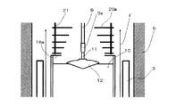
本発明では、ヒータシールドによるArガス流の制御によらずに、温度勾配制御手段を設けることで、原料融液および断熱空間の温度勾配を制御する。このような手段としては、ヒータ出力の調整、断熱材の選択、熱遮蔽板または熱反射板の設置などが挙げられる。この中でも、温度勾配の制御の容易性、安定性およびエネルギコストなどの観点から、熱反射板を用いて垂直方向の温度勾配を制御することが好ましい。特に、本発明では、図1に示されるように、原料融液の上方であって、坩堝と同軸上に、少なくとも1枚以上の円輪状の熱反射板を設置することにより温度勾配を制御することが好ましい。このように熱反射板を設置することにより、原料融液および断熱空間の垂直方向の温度勾配を大きくすることができ、育成中のサファイア単結晶が急成長することを防止することができ、もって、ボイドやリネージなどの結晶欠陥が発生することを防止することができる。
(A) Vertical Temperature Gradient Control Unit In the present invention, the temperature gradient of the raw material melt and the heat insulating space is controlled by providing the temperature gradient control unit without controlling the Ar gas flow by the heater shield. Examples of such means include adjustment of heater output, selection of a heat insulating material, installation of a heat shielding plate or a heat reflecting plate, and the like. Among these, it is preferable to control the temperature gradient in the vertical direction using a heat reflecting plate from the viewpoint of ease of control of the temperature gradient, stability, energy cost, and the like. In particular, in the present invention, as shown in FIG. 1, the temperature gradient is controlled by installing at least one or more annular heat reflectors above the raw material melt and coaxially with the crucible. It is preferable. By installing the heat reflecting plate in this way, the temperature gradient in the vertical direction of the raw material melt and the heat insulation space can be increased, and the sapphire single crystal being grown can be prevented from growing rapidly. It is possible to prevent the occurrence of crystal defects such as voids and lineage.
この熱反射板の設置枚数や配置は、使用する結晶育成装置のヒータ出力、断熱材の材質および厚さなどを総合的に判断して、所望の温度勾配を形成することができるように設計されるべきものであるが、予めシミュレーションにより得られたデータに基づいて設計することが好ましい。 The number and arrangement of the heat reflecting plates are designed so that a desired temperature gradient can be formed by comprehensively judging the heater output of the crystal growth apparatus to be used, the material and thickness of the heat insulating material, and the like. Although it should be, it is preferable to design based on data obtained by simulation in advance.
これらの手段を用いて形成される原料融液内の垂直方向の温度勾配は、原料融液の表面から下方に向かう方向に2℃/cm〜5℃/cmとなるように制御することが好ましく、3℃/cm〜4℃/cmとなるように制御することがより好ましい。また、原料融液上方の温度勾配は、該原料融液の表面から上方に向かう方向に1℃/cm〜4℃/cmとなるように制御することが好ましく、2℃/cm〜3℃/cmとなるように制御することがより好ましい。各温度勾配が、このような範囲にある場合には、原料融液の上方における垂直方向の温度勾配の急峻化が達成でき、結晶育成の初期段階から、成長界面の形状を下凸に維持しやすく、結晶欠陥の発生を抑制することができる。原料融液内および上方の垂直方向の温度勾配が上記下限値未満では、結晶成長速度の制御が困難となり、この場合、融液表面の温度が融点より2℃以上低いと、サファイア単結晶が急成長し、成長界面の形状が下凹となりやすくなり、一方、融液表面の温度が融点より2℃以上高いと、種結晶の融け上がり(種結晶の融解)が起こりやすくなる。また、これらの温度勾配が上記上限値を超えると、サファイア単結晶内の垂直方向の温度差が大きくなるために、転位などの結晶欠陥密度が高くなり、さらには、クラックの発生率が高くなる。いずれの場合であっても、サファイア単結晶の収率の低下の原因となる。 The temperature gradient in the vertical direction in the raw material melt formed by using these means is preferably controlled so as to be 2 ° C./cm to 5 ° C./cm in the downward direction from the surface of the raw material melt. It is more preferable to control the temperature to be 3 ° C / cm to 4 ° C / cm. The temperature gradient above the raw material melt is preferably controlled so as to be 1 ° C./cm to 4 ° C./cm in the upward direction from the surface of the raw material melt. It is more preferable to control to be cm. When each temperature gradient is within such a range, a steep vertical temperature gradient above the raw material melt can be achieved, and the shape of the growth interface can be maintained downward from the initial stage of crystal growth. It is easy to suppress the generation of crystal defects. If the temperature gradient in the raw material melt and in the upper vertical direction is less than the above lower limit value, it is difficult to control the crystal growth rate. In this case, if the temperature of the melt surface is 2 ° C. or more lower than the melting point, It grows and the shape of the growth interface tends to be concave and concave. On the other hand, if the temperature of the melt surface is 2 ° C. or higher than the melting point, the seed crystal is likely to melt (melt the seed crystal). When these temperature gradients exceed the upper limit, the temperature difference in the vertical direction in the sapphire single crystal increases, so that the density of crystal defects such as dislocations increases, and the rate of occurrence of cracks increases. . In either case, the yield of the sapphire single crystal is reduced.
このような原料融液表面近傍の垂直方向の温度勾配の制御は、熟練者のヒータ出力の調整やヒータと坩堝の相対位置の調整などでもある程度可能であるが、図1に示すような、多層型熱反射板を設け、熱反射板の数、形状などを制御して、原料融液からの輻射を制御することにより、この原料融液の垂直方向の温度勾配を制御することを容易に達成することができる。 Such control of the temperature gradient in the vertical direction in the vicinity of the surface of the raw material melt is possible to some extent by adjusting the heater output of the skilled worker or adjusting the relative position of the heater and the crucible, but as shown in FIG. Easily control the temperature gradient in the raw material melt by controlling the radiation from the raw material melt by controlling the number and shape of the heat reflectors. can do.
なお、多層型熱反射板とは、断熱空間内に支持される保持部材と、該保持部材に前記引き上げ軸の軸方向に所定間隔をもって配置固定され、径方向中央部に開口を有する円輪状の熱反射板を、少なくとも2枚以上積層したものをいう。このような多層型熱反射板を構成する各熱反射板および保持部材の材料としては、2000℃以上の高温環境下で容易に変形しないものであれば特に限定されることはなく、たとえば、モリブデン(Mo)、タングステン(W)またはこれらの合金を用いることができる。 The multi-layer heat reflecting plate is a holding member supported in the heat insulating space, and a ring-shaped member that is arranged and fixed to the holding member at a predetermined interval in the axial direction of the lifting shaft, and has an opening at a central portion in the radial direction. This refers to a laminate of at least two heat reflecting plates. The material of each heat reflecting plate and the holding member constituting such a multilayer heat reflecting plate is not particularly limited as long as it does not easily deform under a high temperature environment of 2000 ° C. or higher. For example, molybdenum (Mo), tungsten (W), or an alloy thereof can be used.
(b)接触防止手段
接触防止手段は、断熱空間内のArガスが、原料融液および育成中のサファイア単結晶の肩部側面と接触することを防止し、得られるサファイア単結晶にクビレや二段肩が生じたり、不純物(主に炭素、モリブデン、タングステンなどの炉内構成材に用いている元素)が混入したりすることを防止することを目的とするものである。
(B) Contact prevention means The contact prevention means prevents Ar gas in the heat-insulating space from coming into contact with the raw material melt and the shoulder side surface of the growing sapphire single crystal. The purpose is to prevent the occurrence of shoulders and the entry of impurities (mainly elements used in the in-furnace materials such as carbon, molybdenum, tungsten).
接触防止手段としては、特開平5−294783号公報のような円筒状の遮蔽壁や、後述するリッド(蓋)を坩堝の上縁に設置する手段が挙げられるが、上述したような熱反射板を設置する際に、炉体の天井から下方に伸張する支柱を介して、該熱反射板を支持することが好ましい。 Examples of the contact preventing means include a cylindrical shielding wall as disclosed in Japanese Patent Application Laid-Open No. 5-29483, and means for installing a lid (lid) described later on the upper edge of the crucible. When installing the heat reflecting plate, it is preferable to support the heat reflecting plate through a support column extending downward from the ceiling of the furnace body.
このような構成を有する装置では、原料融液の水平方向および垂直方向のいずれにおいても、温度勾配を大きく維持できる効果を得ながら、断熱材6の内側壁と、該熱反射板の外周部または支柱との間に略円筒状の空間を形成することができ、これにより、高温に熱せられたArガスを、原料融液表面近傍に滞留させることなく、断熱空間へ流通させることが可能となる。
In the apparatus having such a configuration, the inner wall of the
この断熱材6の内側壁と、熱反射板の外周部または支柱との間隔は、好ましくは熱反射板の外径の3%〜15%、より好ましくは熱反射板の外径の7%〜10%とする。この間隔が熱反射板の外径の3%未満では、Arガスの流通が阻害され、原料融液近傍に滞留することを十分に防止することができない。一方、熱反射板の外径の15%を超えると、熱反射板の反射部の形状または寸法が制限される場合があり、効率よく輻射を利用することができなくなるおそれがある。
The distance between the inner wall of the
また、各熱反射板の断面形状は、従来のヒータシールドのように略円錐形状ではなく、円盤状(径方向に直線状)であることが好ましい。これにより、これらの熱反射板に沿って、径方向内方に侵入してきたArガスが、原料融液の表面に向かって流れることはないため、カーボン蒸気を含むArガスと原料融液との直接接触を実質的に阻止することが可能となる。 Moreover, it is preferable that the cross-sectional shape of each heat reflecting plate is not a substantially conical shape like a conventional heater shield but a disc shape (linear shape in the radial direction). Thereby, since Ar gas which has penetrated radially inward along these heat reflecting plates does not flow toward the surface of the raw material melt, the Ar gas containing carbon vapor and the raw material melt It is possible to substantially prevent direct contact.
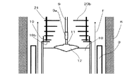
なお、原料融液とArガス流の接触を確実に防止するためには、図1に示すように円盤状のリッド(蓋)18aを坩堝の上端部に設置することが好ましく、図2に示すように該リッドの上面に突起部19を設けたものを設置することがより好ましい。
In order to reliably prevent contact between the raw material melt and the Ar gas flow, it is preferable to install a disc-shaped lid (lid) 18a at the upper end of the crucible as shown in FIG. 1, as shown in FIG. As described above, it is more preferable to install the lid provided with the
リッド18aの外径は、坩堝1の外径と同じか、これよりも1mm〜2mm程度大きいことが好ましい。また、その内径は、育成するサファイア単結晶と接触しない大きさであればよいが、シミュレーションにより予測されるArガス流を考慮して適宜調整することが好ましい。具体的には、リッド18aの内径は、坩堝1の内径の70%〜90%の範囲、すなわち、坩堝1の内径が300mmのときには、この坩堝1の内径より30mm〜90mm程度小さい内径とする。
The outer diameter of the
また、突起部19は、最下部の熱反射板と接触しないように調整すれば、その形状などについては特に限定されることはない。好ましくは、突起部19の高さは、坩堝1の高さの30%〜100%程度、すなわち、坩堝1の高さが300mmのときには、90mm〜300mm程度とする。
Moreover, if the
このようなリッドおよび突起部の構成材料としては、高温環境下で容易に変形しないことが重要であり、たとえば、モリブデン(Mo)、タングステン(W)、または、炭化タンタル(TaC)などで構成されか、あるいは、これらの材料でコーディングされることが好ましく、この中でもカーボンと反応することがない炭化タンタル(TaC)を用いることが好ましい。 As a constituent material of such a lid and a protrusion, it is important that the lid and the protrusion are not easily deformed in a high temperature environment. For example, the lid and the protrusion are made of molybdenum (Mo), tungsten (W), tantalum carbide (TaC), or the like. Alternatively, it is preferably coded with these materials, and among these, tantalum carbide (TaC) that does not react with carbon is preferably used.
(c)径方向温度勾配制御手段
上述のように垂直方向の温度勾配を適切に制御した場合であっても、原料融液の径方向の温度勾配を十分に大きくすることができない場合には、育成中、特に育成初期段階のサファイア単結晶の成長界面の形状が下凸に維持することが困難となる場合がある。これを防止するためには、上記製造装置に、径方向温度勾配制御手段をさらに加えることが好ましい。
(C) Radial temperature gradient control means Even when the temperature gradient in the vertical direction is appropriately controlled as described above, if the temperature gradient in the radial direction of the raw material melt cannot be sufficiently increased, During the growth, it may be difficult to keep the shape of the growth interface of the sapphire single crystal in the initial stage of growth particularly downward. In order to prevent this, it is preferable to further add a radial temperature gradient control means to the manufacturing apparatus.
このような手段として、具体的には、前記熱反射板の設置枚数や配置を設計する際に、原料融液の径方向の温度勾配を加味した上で設計すること、ヒータ出力の調整または断熱材の選択などが挙げられる。 As such means, specifically, when designing the number and arrangement of the heat reflecting plates, it should be designed taking into account the temperature gradient in the radial direction of the raw material melt, adjustment of the heater output or heat insulation. Examples include selection of materials.
いずれの手段を採用する場合であっても、原料融液の径方向の温度勾配は、その中心部から外周部に向かう方向に好ましくは2℃/mm〜5℃/mm、より好ましくは3℃/mm〜4℃/mmとする。上述の垂直方向の温度勾配と合わせて、径方向の温度勾配をこのような範囲に制御することで、サファイア単結晶の結晶径が急成長することを、効果的に防止することができる。前記温度勾配が2℃/mm未満ではサファイア単結晶の結晶径の急成長を抑制することができず、また、5℃/mmを超えるとクラック発生率が高くなるという問題が生じる。 Regardless of which means is employed, the temperature gradient in the radial direction of the raw material melt is preferably 2 ° C./mm to 5 ° C./mm, more preferably 3 ° C. in the direction from the center to the outer periphery. / Mm to 4 ° C./mm. By controlling the temperature gradient in the radial direction in such a range together with the above-described temperature gradient in the vertical direction, it is possible to effectively prevent the crystal diameter of the sapphire single crystal from growing rapidly. If the temperature gradient is less than 2 ° C./mm, rapid growth of the crystal diameter of the sapphire single crystal cannot be suppressed, and if it exceeds 5 ° C./mm, the crack generation rate increases.
以下、本発明を実施例により、さらに詳細に説明する。 Hereinafter, the present invention will be described in more detail with reference to examples.
なお、以下の実施例および比較例において、偏光検査は、得られたサファイア基板をヨウ化メチレンに浸して白色光源を照射することで行った。また、X線トポグラフは、大試料ラングカメラ(株式会社リガク製、LGL−8)により、表面平坦度は、光学式表面平坦度測定器(株式会社ニデック製、フタットネステスター FT−900)により評価した。 In the following Examples and Comparative Examples, the polarization inspection was performed by immersing the obtained sapphire substrate in methylene iodide and irradiating with a white light source. The X-ray topograph is measured with a large sample Lang camera (manufactured by Rigaku Corporation, LGL-8), and the surface flatness is measured with an optical surface flatness measuring instrument (manufactured by Nidec Co., Ltd., FT Nestester FT-900). evaluated.
(実施例1)
ヒータシールド13を除いて、図4に示す基本構成の結晶育成装置を使用して、サファイア単結晶の育成を行った。本実施例では、ヒータシールドの代わりに、図1に示すような多層型熱反射板を設置することにより、原料融液および断熱空間の垂直方向の温度勾配を制御するとともに、坩堝の上端縁から径方向内方に伸張するリッドを設置することにより、Arガス流と原料融液および育成中のサファイア単結晶の肩部側面との接触を防止した。このとき、断熱材の内側壁と熱反射板の外周部との間隔は、20mmとした。また、リッドとしては、坩堝の内径よりも60mm小さい内径を有するものを使用した。なお、育成方位はa軸方向とした。
Example 1
A sapphire single crystal was grown using the crystal growth apparatus having the basic configuration shown in FIG. 4 except for the
初めに、原料として酸化アルミニウム(Al2O3)粉末を、モリブデン(Mo)製の坩堝(直径300mm、高さ300mm)に挿入し、この坩堝を結晶育成装置の支持軸上に設置した。このとき、坩堝底の位置が、断熱空間15内において、カーボン製ヒータ3、4により最高温度となる位置と一致するように坩堝の垂直方向の位置を調整した。また、モリブデン(Mo)製の引き上げ軸に、モリブデン(Mo)製のホルダを介して種結晶を設置した。
First, aluminum oxide (Al 2 O 3 ) powder as a raw material was inserted into a crucible made of molybdenum (Mo) (diameter 300 mm, height 300 mm), and this crucible was placed on the support shaft of the crystal growth apparatus. At this time, the position of the crucible in the vertical direction was adjusted so that the position of the bottom of the crucible coincided with the position of the maximum temperature by the
その後、断熱部材を密閉し、断熱空間を形成した後、Arガス雰囲気とし、ヒータ3、4により酸化アルミニウム(Al2O3)粉末を2050℃以上に加熱し、該粉末を融解した。酸化アルミニウム(Al2O3)粉末が完全に融解したことを確認した後、先端に種結晶が取り付けられた引き上げ軸を5rpmで回転させた状態で下降させ、酸化アルミニウム(Al2O3)融液に接触させた。このとき、熱反射板と坩堝底間の平均温度勾配が3℃/cmとなるように、ヒータ3、4の出力を調整した。
Thereafter, the heat insulating member was sealed to form a heat insulating space, and then an Ar gas atmosphere was created. The aluminum oxide (Al 2 O 3 ) powder was heated to 2050 ° C. or higher by the
サファイア単結晶育成の初期段階、具体的には、結晶育成を開始してから肩部が形成されるまでの間の育成結晶の引き上げ速度は、1mm/hrに調整した。このとき、原料融液内の垂直方向の温度勾配は、該融液表面から下方に向かう方向に3℃/cm〜4℃/cm、原料融液上方の垂直方向の温度勾配は、該融液表面から上方に向かう方向に2℃/cm〜3℃/cmとなるように熱反射板の位置を調整した。このときの、原料融液表面の径方向の温度勾配は、中心部から外周部に向かう方向に3℃/cm〜4℃/cmであった。これらのパラメータの値は、サファイア単結晶の育成を開始する前に、予備試験として、ヒータ3、4の出力比やヒータと坩堝の相対位置などと、温度勾配との関係を、放射型温度計やタングステン−レニウム(W−Re)熱電対などを用いて測定して得られたデータに基づいて、調整されたものである。また、この予備試験において、結晶肩部のみの育成を行い、上記パラメータの値の下では、サファイア単結晶が急成長しないこと、および、成長界面の形状は下凸を保たれることを確認した。
The initial stage of sapphire single crystal growth, specifically, the pulling rate of the grown crystal between the start of crystal growth and the formation of the shoulder was adjusted to 1 mm / hr. At this time, the vertical temperature gradient in the raw material melt is 3 ° C./cm to 4 ° C./cm in the downward direction from the melt surface, and the vertical temperature gradient above the raw material melt is The position of the heat reflecting plate was adjusted so as to be 2 ° C./cm to 3 ° C./cm in the upward direction from the surface. At this time, the temperature gradient in the radial direction on the surface of the raw material melt was 3 ° C./cm to 4 ° C./cm in the direction from the center to the outer periphery. Before starting the growth of the sapphire single crystal, the values of these parameters are preliminarily tested as the relationship between the output gradient of the
育成中にモニターした結晶成長速度と育成後に取出した結晶内の欠陥観察から、結晶育成の初期段階では、予備試験の結果通りに結晶径の急成長は確認されず、サファイア単結晶の成長界面の形状は下凸を保っていたと考えられる。この状態を維持したまま、5日間の引き上げを行った。 From the crystal growth rate monitored during growth and the observation of defects in the crystal taken out after growth, in the initial stage of crystal growth, no rapid growth of the crystal diameter was confirmed as the result of the preliminary test, and the growth interface of the sapphire single crystal It is thought that the shape was maintaining a downward convexity. While maintaining this state, it was lifted for 5 days.
この結果、35kg(直径:200mm、長さ:280mm)のサファイア単結晶を得た。このサファイア単結晶は、肩部の形状がなだらかであり、また、偏光検査により観察した結果、その内部に、粒界、リネージはもちろんのこと、ボイドなどの結晶欠陥はほとんど確認されなかった。加えて、ICP法による不純物分析を実施したところ、モリブデン(Mo)濃度は検出下限(1ppm)程度であった。 As a result, a sapphire single crystal of 35 kg (diameter: 200 mm, length: 280 mm) was obtained. This sapphire single crystal has a gentle shoulder shape, and as a result of observation by polarization inspection, crystal defects such as voids as well as grain boundaries and lineage were not confirmed. In addition, when impurity analysis was performed by the ICP method, the molybdenum (Mo) concentration was about the lower limit of detection (1 ppm).
このサファイア単結晶に対して、スライス加工および研磨加工をすることにより、厚さ1mmの4inφのc面サファイア基板を200枚得た。X線トポグラフ、表面平坦度測定などで得られた基板を評価したところ、良品率は96%であった。この結果を表1に示す。 By subjecting this sapphire single crystal to slicing and polishing, 200 c-plane sapphire substrates having a thickness of 1 mm and 4 inφ were obtained. When the substrate obtained by X-ray topography, surface flatness measurement or the like was evaluated, the yield rate was 96%. The results are shown in Table 1.
(実施例2)
図2に示すような多層型熱反射板およびリッドを使用したこと以外は、実施例1と同様にして、サファイア単結晶の育成を行った。本実施例では、リッドとして、該リッドの上面から上方へ150mm(坩堝の高さの50%)伸長する円筒状の突起部が設けられているものを使用した。
(Example 2)
A sapphire single crystal was grown in the same manner as in Example 1 except that a multilayer heat reflecting plate and a lid as shown in FIG. 2 were used. In the present example, a lid provided with a cylindrical projection extending 150 mm (50% of the height of the crucible) upward from the upper surface of the lid was used.
この結晶育成の初期段階では、結晶径の急成長は確認されず、また、サファイア単結晶の成長界面の形状は下凸を保っていたと考えられる。この状態を維持したまま、5日間の引き上げを行った。育成開始時の原料融液内の垂直方向の温度勾配は、該融液表面から下方に向かう方向に3℃/mm〜4℃/mm、上方の垂直方向の温度勾配は、該融液表面から上方に向かう方向に2℃/mm〜3℃/mmとなるように調整した。また、原料融液表面の径方向の温度勾配は、その中心部から外周部に向かう方向に3℃/mm〜4℃/mmとなるように調整した。 In this initial stage of crystal growth, rapid growth of the crystal diameter was not confirmed, and it is considered that the shape of the growth interface of the sapphire single crystal remained downwardly convex. While maintaining this state, it was lifted for 5 days. The vertical temperature gradient in the raw material melt at the start of growth is 3 ° C./mm to 4 ° C./mm in the downward direction from the melt surface, and the upper vertical temperature gradient is from the melt surface. It adjusted so that it might become 2 degrees C / mm-3 degrees C / mm in the direction which goes upwards. Further, the temperature gradient in the radial direction on the surface of the raw material melt was adjusted to be 3 ° C./mm to 4 ° C./mm in the direction from the center to the outer periphery.
この結果、35kg(直径:200mm、長さ:280mm)のサファイア単結晶を得た。このサファイア単結晶は、肩部の形状がなだらかであり、また、偏光検査により観察した結果、その内部に、粒界、リネージはもちろんのこと、ボイドなどの結晶欠陥はほとんど確認されなかった。加えて、ICP法による不純物分析を実施したところ、モリブデン(Mo)濃度は検出下限(1ppm)以下であった。 As a result, a sapphire single crystal of 35 kg (diameter: 200 mm, length: 280 mm) was obtained. This sapphire single crystal has a gentle shoulder shape, and as a result of observation by polarization inspection, crystal defects such as voids as well as grain boundaries and lineage were not confirmed. In addition, when impurity analysis was performed by ICP method, the molybdenum (Mo) concentration was below the lower limit of detection (1 ppm).
このサファイア単結晶に対して、スライス加工および研磨加工をすることにより、厚さ1mmの4inφのc面サファイア基板を200枚得た。X線トポグラフ、表面平坦度測定などで得られた基板を評価したところ、良品率は98%であった。この結果を表1に示す。 By subjecting this sapphire single crystal to slicing and polishing, 200 c-plane sapphire substrates having a thickness of 1 mm and 4 inφ were obtained. When the substrate obtained by X-ray topography, surface flatness measurement or the like was evaluated, the yield rate was 98%. The results are shown in Table 1.
(比較例1)
図4に示されるようなヒータシールドを使用し、Arガスによる温度勾配の制御を行ったこと以外は、実施例1と同様にして、サファイア単結晶の育成を行った。本比較例では、結晶育成の初期段階で、結晶径が急成長し、育成後に取出した結晶内部の欠陥観察から、成長界面の形状を下凸に維持することができなかったことが確認された。その後、5日間の引き上げを行った。育成開始時の、原料融液内の垂直方向の温度勾配は1℃/mm〜2℃/mm、断熱空間の垂直方向の温度勾配は1℃/mm〜2℃/mm、原料融液表面の水平方向の温度勾配も1℃/mm〜2℃/mmであった。
(Comparative Example 1)
A sapphire single crystal was grown in the same manner as in Example 1 except that a heater shield as shown in FIG. 4 was used and the temperature gradient was controlled by Ar gas. In this comparative example, the crystal diameter grew rapidly in the initial stage of crystal growth, and it was confirmed from the observation of defects inside the crystal taken out after the growth that the shape of the growth interface could not be maintained downwardly convex. . After that, it was raised for 5 days. The temperature gradient in the vertical direction in the raw material melt at the start of growth is 1 ° C./mm to 2 ° C./mm, the temperature gradient in the vertical direction of the heat insulating space is 1 ° C./mm to 2 ° C./mm, The temperature gradient in the horizontal direction was also 1 ° C./mm to 2 ° C./mm.
この結果、35kg(直径:200mm、長さ:280mm)のサファイア単結晶を得た。このサファイア単結晶は、クビレや二段肩が発生しており、偏光検査による観察では、内部にボイド、粒界などの結晶欠陥は確認された。また、ICP法による不純物分析を実施したところ、不純物として金属モリブデン(Mo)粒子が混入していることも確認された。 As a result, a sapphire single crystal of 35 kg (diameter: 200 mm, length: 280 mm) was obtained. This sapphire single crystal has necks and double shoulders, and observations by polarization inspection confirmed crystal defects such as voids and grain boundaries inside. Further, when impurity analysis by ICP method was performed, it was also confirmed that metal molybdenum (Mo) particles were mixed as impurities.
このサファイア単結晶に対して、スライス加工および研磨加工をすることにより、厚さ1mmの4inφのc面サファイア基板を200枚得た。X線トポグラフ、表面平坦度測定などで得られた基板を評価したところ、良品率は65%であった。この結果を表1に示す。 By subjecting this sapphire single crystal to slicing and polishing, 200 c-plane sapphire substrates having a thickness of 1 mm and 4 inφ were obtained. When the substrate obtained by X-ray topography, surface flatness measurement or the like was evaluated, the yield rate was 65%. The results are shown in Table 1.
1 坩堝
2 支持軸
3 円筒状ヒータ
4 円盤状ヒータ
5a、5b ヒータ電極
6 断熱材
7 炉体
8 絶縁筒
9 引き上げ軸
9a ホルダ
10 原料融液
11 種結晶
12、12a、12b、12c サファイア単結晶
13 ヒータシールド
14 ステー(支持部材)
15 断熱空間
16 底面部
17 上面部
18a、18b リッド(蓋)
19 突起部
20a、20b 多層型熱反射板
21 支柱
22a、22b サファイア単結晶
23 クビレ
24 二段肩
25 気泡(ボイド)
26 粒界(多結晶)
F Arガス流
DESCRIPTION OF SYMBOLS 1
15
19
26 Grain boundary (Polycrystalline)
F Ar gas flow
Claims (6)
炉体内に断熱空間を形成するカーボン製断熱材と、該断熱空間内に配置され原料融液を収容する坩堝と、該坩堝を前記断熱空間内に支持する支持軸と、前記断熱空間内まで伸長し、前記坩堝の上方に育成したサファイア単結晶を引き上げる引き上げ軸と、前記断熱空間内に配置され、前記坩堝の周囲に配置されるカーボン製ヒータとを備えるとともに、
前記坩堝の外周部の上方で、該坩堝の外周部と前記断熱材の内周面との間には、下方からのガス流を前記坩堝内の前記原料融液に向けて転向させる障害物が設置されておらず、
前記断熱空間内において、前記坩堝の上方で、かつ、前記原料融液の上方に、前記坩堝と同軸上に配置され、少なくとも1枚以上の径方向中央部に開口を有する円輪状の熱反射板からなり、前記原料融液からの輻射を制御することにより、前記原料融液および断熱空間の垂直方向の温度勾配を制御する手段と、
前記坩堝の上端縁に設置され、前記下方からのガス流と、前記原料融液および育成中のサファイア単結晶の肩部側面との接触を防止する手段と、
をさらに備える、サファイア単結晶育成装置。 An apparatus for producing a sapphire single crystal by the Czochralski method,
A carbon heat insulating material that forms a heat insulating space in the furnace body, a crucible that is disposed in the heat insulating space and accommodates a raw material melt, a support shaft that supports the crucible in the heat insulating space, and extends into the heat insulating space. And a pulling shaft for pulling up the sapphire single crystal grown above the crucible, and a carbon heater disposed in the heat insulating space and disposed around the crucible,
Above the outer periphery of the crucible, between the outer periphery of the crucible and the inner peripheral surface of the heat insulating material, there is an obstacle that turns the gas flow from below toward the raw material melt in the crucible. Not installed,
In the heat insulation space, above the crucible and above the raw material melt, is arranged coaxially with the crucible and has an annular heat reflecting plate having an opening in at least one radial central portion. Means for controlling a temperature gradient in a vertical direction of the raw material melt and the heat insulation space by controlling radiation from the raw material melt,
Means installed on the upper edge of the crucible to prevent contact between the gas flow from below and the shoulder side surface of the raw material melt and the growing sapphire single crystal;
A sapphire single crystal growing device further comprising:
Priority Applications (1)
| Application Number | Priority Date | Filing Date | Title |
|---|---|---|---|
| JP2012213141A JP5888198B2 (en) | 2012-09-26 | 2012-09-26 | Sapphire single crystal manufacturing equipment |
Applications Claiming Priority (1)
| Application Number | Priority Date | Filing Date | Title |
|---|---|---|---|
| JP2012213141A JP5888198B2 (en) | 2012-09-26 | 2012-09-26 | Sapphire single crystal manufacturing equipment |
Publications (2)
| Publication Number | Publication Date |
|---|---|
| JP2014065639A JP2014065639A (en) | 2014-04-17 |
| JP5888198B2 true JP5888198B2 (en) | 2016-03-16 |
Family
ID=50742416
Family Applications (1)
| Application Number | Title | Priority Date | Filing Date |
|---|---|---|---|
| JP2012213141A Expired - Fee Related JP5888198B2 (en) | 2012-09-26 | 2012-09-26 | Sapphire single crystal manufacturing equipment |
Country Status (1)
| Country | Link |
|---|---|
| JP (1) | JP5888198B2 (en) |
Families Citing this family (4)
| Publication number | Priority date | Publication date | Assignee | Title |
|---|---|---|---|---|
| JP6451700B2 (en) * | 2016-06-29 | 2019-01-16 | 住友金属鉱山株式会社 | Oxide single crystal growth method |
| KR102227148B1 (en) * | 2019-02-14 | 2021-03-15 | 한국세라믹기술원 | Variable reflector for crystal growth device |
| CN111850687A (en) * | 2020-07-22 | 2020-10-30 | 哈尔滨秋硕半导体科技有限公司 | A kind of crucible cover structure for sapphire single crystal furnace by foaming method |
| CN116200802B (en) * | 2022-09-09 | 2026-01-13 | 浙江晶盛机电股份有限公司 | Heat insulation mechanism, single crystal furnace and re-casting method |
Family Cites Families (6)
| Publication number | Priority date | Publication date | Assignee | Title |
|---|---|---|---|---|
| DE2528585C3 (en) * | 1974-06-28 | 1979-10-11 | Union Carbide Corp., New York, N.Y. (V.St.A.) | Process for the production of doped a -alumina single crystals |
| DE2555610C3 (en) * | 1974-12-20 | 1979-11-22 | Union Carbide Corp., New York, N.Y. (V.St.A.) | Process for the production of A -alumina single crystals |
| JPS61247683A (en) * | 1985-04-23 | 1986-11-04 | Seiko Epson Corp | Single crystal sapphire pulling device |
| JPH11189487A (en) * | 1997-12-25 | 1999-07-13 | Toshiba Corp | Oxide single crystal manufacturing equipment |
| JP2003327490A (en) * | 2002-05-15 | 2003-11-19 | Mitsui Chemicals Inc | Method for producing oxide single crystal and production apparatus used in the same |
| JP2008007353A (en) * | 2006-06-28 | 2008-01-17 | Sumitomo Metal Mining Co Ltd | Sapphire single crystal growth apparatus and growth method using the same |
-
2012
- 2012-09-26 JP JP2012213141A patent/JP5888198B2/en not_active Expired - Fee Related
Also Published As
| Publication number | Publication date |
|---|---|
| JP2014065639A (en) | 2014-04-17 |
Similar Documents
| Publication | Publication Date | Title |
|---|---|---|
| CN109196144B (en) | Method and device for producing single crystal silicon | |
| KR101708131B1 (en) | SiC SINGLE CRYSTAL INGOT AND PRODUCTION METHOD THEREFOR | |
| KR101710814B1 (en) | Method for producing sic single crystal | |
| JP5888198B2 (en) | Sapphire single crystal manufacturing equipment | |
| JP6107308B2 (en) | Silicon single crystal manufacturing method | |
| JP2014162665A (en) | Production method of sapphire single crystal | |
| JP2016033102A (en) | Sapphire single crystal and manufacturing method thereof | |
| JP2016150877A (en) | Production method of sapphire single crystal | |
| JP2014162673A (en) | Sapphire single crystal core and manufacturing method of the same | |
| JP4830312B2 (en) | Compound semiconductor single crystal and manufacturing method thereof | |
| JP4844429B2 (en) | Method for producing sapphire single crystal | |
| JP5949601B2 (en) | Multi-layered heat reflector and oxide single crystal growth apparatus using the same | |
| JP2016130205A (en) | Method for producing sapphire single crystal | |
| JP2013256424A (en) | Apparatus for growing sapphire single crystal | |
| JP2006151745A (en) | Method for producing single crystal and oxide single crystal using them | |
| JP2010265150A (en) | Method for producing sapphire single crystal and method for producing seed crystal | |
| JP5651480B2 (en) | Method for producing group 3B nitride crystals | |
| JP2011057460A (en) | Method for growing silicon single crystal | |
| JP4940610B2 (en) | Sapphire single crystal growth method | |
| JP2013193942A (en) | Single crystal manufacturing apparatus and method for manufacturing single crystal using the same | |
| KR20140024140A (en) | Apparatus for growing sapphire single crystal | |
| JP4821623B2 (en) | Single crystal growth crucible and fluoride crystal grown by this crucible | |
| JP2013049608A (en) | Large-diameter sapphire single crystal substrate | |
| KR20190075411A (en) | Crucible Member Capable of Removing Lineage Defect, Apparatus and Method for Growing Sapphire Single Crystal of High Quality Using the Same | |
| JP2016169112A (en) | Method for producing sapphire single crystal |
Legal Events
| Date | Code | Title | Description |
|---|---|---|---|
| A621 | Written request for application examination |
Free format text: JAPANESE INTERMEDIATE CODE: A621 Effective date: 20141205 |
|
| A977 | Report on retrieval |
Free format text: JAPANESE INTERMEDIATE CODE: A971007 Effective date: 20150918 |
|
| A131 | Notification of reasons for refusal |
Free format text: JAPANESE INTERMEDIATE CODE: A131 Effective date: 20151027 |
|
| A521 | Written amendment |
Free format text: JAPANESE INTERMEDIATE CODE: A523 Effective date: 20151221 |
|
| TRDD | Decision of grant or rejection written | ||
| A01 | Written decision to grant a patent or to grant a registration (utility model) |
Free format text: JAPANESE INTERMEDIATE CODE: A01 Effective date: 20160119 |
|
| A61 | First payment of annual fees (during grant procedure) |
Free format text: JAPANESE INTERMEDIATE CODE: A61 Effective date: 20160201 |
|
| R150 | Certificate of patent or registration of utility model |
Ref document number: 5888198 Country of ref document: JP Free format text: JAPANESE INTERMEDIATE CODE: R150 |
|
| LAPS | Cancellation because of no payment of annual fees |