JP5886552B2 - Exhaust structure of construction machinery - Google Patents
Exhaust structure of construction machinery Download PDFInfo
- Publication number
- JP5886552B2 JP5886552B2 JP2011157830A JP2011157830A JP5886552B2 JP 5886552 B2 JP5886552 B2 JP 5886552B2 JP 2011157830 A JP2011157830 A JP 2011157830A JP 2011157830 A JP2011157830 A JP 2011157830A JP 5886552 B2 JP5886552 B2 JP 5886552B2
- Authority
- JP
- Japan
- Prior art keywords
- exhaust
- exhaust gas
- duct
- engine room
- gas pipe
- Prior art date
- Legal status (The legal status is an assumption and is not a legal conclusion. Google has not performed a legal analysis and makes no representation as to the accuracy of the status listed.)
- Active
Links
Images


Classifications
-
- E—FIXED CONSTRUCTIONS
- E02—HYDRAULIC ENGINEERING; FOUNDATIONS; SOIL SHIFTING
- E02F—DREDGING; SOIL-SHIFTING
- E02F9/00—Component parts of dredgers or soil-shifting machines, not restricted to one of the kinds covered by groups E02F3/00 - E02F7/00
- E02F9/08—Superstructures; Supports for superstructures
- E02F9/0858—Arrangement of component parts installed on superstructures not otherwise provided for, e.g. electric components, fenders, air-conditioning units
- E02F9/0866—Engine compartment, e.g. heat exchangers, exhaust filters, cooling devices, silencers, mufflers, position of hydraulic pumps in the engine compartment
-
- B—PERFORMING OPERATIONS; TRANSPORTING
- B60—VEHICLES IN GENERAL
- B60K—ARRANGEMENT OR MOUNTING OF PROPULSION UNITS OR OF TRANSMISSIONS IN VEHICLES; ARRANGEMENT OR MOUNTING OF PLURAL DIVERSE PRIME-MOVERS IN VEHICLES; AUXILIARY DRIVES FOR VEHICLES; INSTRUMENTATION OR DASHBOARDS FOR VEHICLES; ARRANGEMENTS IN CONNECTION WITH COOLING, AIR INTAKE, GAS EXHAUST OR FUEL SUPPLY OF PROPULSION UNITS IN VEHICLES
- B60K13/00—Arrangement in connection with combustion air intake or gas exhaust of propulsion units
- B60K13/04—Arrangement in connection with combustion air intake or gas exhaust of propulsion units concerning exhaust
-
- F—MECHANICAL ENGINEERING; LIGHTING; HEATING; WEAPONS; BLASTING
- F01—MACHINES OR ENGINES IN GENERAL; ENGINE PLANTS IN GENERAL; STEAM ENGINES
- F01N—GAS-FLOW SILENCERS OR EXHAUST APPARATUS FOR MACHINES OR ENGINES IN GENERAL; GAS-FLOW SILENCERS OR EXHAUST APPARATUS FOR INTERNAL-COMBUSTION ENGINES
- F01N13/00—Exhaust or silencing apparatus characterised by constructional features
- F01N13/08—Other arrangements or adaptations of exhaust conduits
- F01N13/082—Other arrangements or adaptations of exhaust conduits of tailpipe, e.g. with means for mixing air with exhaust for exhaust cooling, dilution or evacuation
-
- F—MECHANICAL ENGINEERING; LIGHTING; HEATING; WEAPONS; BLASTING
- F01—MACHINES OR ENGINES IN GENERAL; ENGINE PLANTS IN GENERAL; STEAM ENGINES
- F01N—GAS-FLOW SILENCERS OR EXHAUST APPARATUS FOR MACHINES OR ENGINES IN GENERAL; GAS-FLOW SILENCERS OR EXHAUST APPARATUS FOR INTERNAL-COMBUSTION ENGINES
- F01N3/00—Exhaust or silencing apparatus having means for purifying, rendering innocuous, or otherwise treating exhaust
- F01N3/02—Exhaust or silencing apparatus having means for purifying, rendering innocuous, or otherwise treating exhaust for cooling, or for removing solid constituents of, exhaust
- F01N3/05—Exhaust or silencing apparatus having means for purifying, rendering innocuous, or otherwise treating exhaust for cooling, or for removing solid constituents of, exhaust by means of air, e.g. by mixing exhaust with air
-
- B—PERFORMING OPERATIONS; TRANSPORTING
- B60—VEHICLES IN GENERAL
- B60K—ARRANGEMENT OR MOUNTING OF PROPULSION UNITS OR OF TRANSMISSIONS IN VEHICLES; ARRANGEMENT OR MOUNTING OF PLURAL DIVERSE PRIME-MOVERS IN VEHICLES; AUXILIARY DRIVES FOR VEHICLES; INSTRUMENTATION OR DASHBOARDS FOR VEHICLES; ARRANGEMENTS IN CONNECTION WITH COOLING, AIR INTAKE, GAS EXHAUST OR FUEL SUPPLY OF PROPULSION UNITS IN VEHICLES
- B60K11/00—Arrangement in connection with cooling of propulsion units
- B60K11/06—Arrangement in connection with cooling of propulsion units with air cooling
-
- B—PERFORMING OPERATIONS; TRANSPORTING
- B60—VEHICLES IN GENERAL
- B60Y—INDEXING SCHEME RELATING TO ASPECTS CROSS-CUTTING VEHICLE TECHNOLOGY
- B60Y2200/00—Type of vehicle
- B60Y2200/40—Special vehicles
- B60Y2200/41—Construction vehicles, e.g. graders, excavators
- B60Y2200/412—Excavators
-
- F—MECHANICAL ENGINEERING; LIGHTING; HEATING; WEAPONS; BLASTING
- F01—MACHINES OR ENGINES IN GENERAL; ENGINE PLANTS IN GENERAL; STEAM ENGINES
- F01N—GAS-FLOW SILENCERS OR EXHAUST APPARATUS FOR MACHINES OR ENGINES IN GENERAL; GAS-FLOW SILENCERS OR EXHAUST APPARATUS FOR INTERNAL-COMBUSTION ENGINES
- F01N2470/00—Structure or shape of exhaust gas passages, pipes or tubes
- F01N2470/02—Tubes being perforated
- F01N2470/04—Tubes being perforated characterised by shape, disposition or dimensions of apertures
-
- F—MECHANICAL ENGINEERING; LIGHTING; HEATING; WEAPONS; BLASTING
- F01—MACHINES OR ENGINES IN GENERAL; ENGINE PLANTS IN GENERAL; STEAM ENGINES
- F01N—GAS-FLOW SILENCERS OR EXHAUST APPARATUS FOR MACHINES OR ENGINES IN GENERAL; GAS-FLOW SILENCERS OR EXHAUST APPARATUS FOR INTERNAL-COMBUSTION ENGINES
- F01N2590/00—Exhaust or silencing apparatus adapted to particular use, e.g. for military applications, airplanes, submarines
- F01N2590/08—Exhaust or silencing apparatus adapted to particular use, e.g. for military applications, airplanes, submarines for heavy duty applications, e.g. trucks, buses, tractors, locomotives
-
- Y—GENERAL TAGGING OF NEW TECHNOLOGICAL DEVELOPMENTS; GENERAL TAGGING OF CROSS-SECTIONAL TECHNOLOGIES SPANNING OVER SEVERAL SECTIONS OF THE IPC; TECHNICAL SUBJECTS COVERED BY FORMER USPC CROSS-REFERENCE ART COLLECTIONS [XRACs] AND DIGESTS
- Y02—TECHNOLOGIES OR APPLICATIONS FOR MITIGATION OR ADAPTATION AGAINST CLIMATE CHANGE
- Y02T—CLIMATE CHANGE MITIGATION TECHNOLOGIES RELATED TO TRANSPORTATION
- Y02T10/00—Road transport of goods or passengers
- Y02T10/10—Internal combustion engine [ICE] based vehicles
- Y02T10/12—Improving ICE efficiencies
Landscapes
- Engineering & Computer Science (AREA)
- Chemical & Material Sciences (AREA)
- General Engineering & Computer Science (AREA)
- Combustion & Propulsion (AREA)
- Mechanical Engineering (AREA)
- Structural Engineering (AREA)
- Civil Engineering (AREA)
- Mining & Mineral Resources (AREA)
- Transportation (AREA)
- Health & Medical Sciences (AREA)
- Chemical Kinetics & Catalysis (AREA)
- Toxicology (AREA)
- Component Parts Of Construction Machinery (AREA)
- Exhaust Silencers (AREA)
- Exhaust Gas After Treatment (AREA)
Description
本発明は油圧ショベル等の建設機械において、エンジンの排ガス及び冷却空気をエンジンルーム外に排出するための排気構造に関するものである。 The present invention relates to an exhaust structure for discharging engine exhaust gas and cooling air to the outside of an engine room in a construction machine such as a hydraulic excavator.
油圧ショベルを例にとって背景技術を説明する。 The background art will be described using a hydraulic excavator as an example.
図9はミニショベルと称される小型の油圧ショベルを示している。 FIG. 9 shows a small hydraulic excavator called a mini excavator.
この油圧ショベルは、下部走行体1上に上部旋回体2が地面に対して鉛直となる軸(旋回中心軸)Oのまわりに旋回自在に搭載され、この上部旋回体2の前部に掘削装置Aが装着されて構成される。
The hydraulic excavator is mounted on the lower traveling body 1 so that the
下部走行体1は、上部旋回体2が搭載されるカーボディ(図示しない)の左右両側にクローラ式走行装置3(片側のみ示す)が取付けられて成っている。
The lower traveling body 1 includes a crawler traveling device 3 (only one side is shown) attached to both left and right sides of a car body (not shown) on which the upper revolving
上部旋回体2を構成するアッパーフレーム4の後部に、アッパーフレーム4、及びパネルやボンネット等のエンジンガード部材5で囲われたエンジンルーム6が設けられ、このエンジンルーム6内にエンジン7とその関連機器が設置される。
An engine room 6 surrounded by an
また、エンジンガード部材5上に運転席8と操作レバー(図示省略)が設けられ、オペレータが運転席8に着座した状態でレバー操作を行う。
A driver's seat 8 and an operation lever (not shown) are provided on the
図9中、9は運転席8を上方から覆うキャノピである。 In FIG. 9, 9 is a canopy that covers the driver's seat 8 from above.
この小型ショベルにおいて、エンジンから排出される高温の排ガスを排ガス管(尾管)によってエンジンルームから外部に直接上向きに排出すると、オペレータが排気熱と排気音を身近に受けるためオペレータの作業環境が悪くなるという問題があった。 In this small excavator, if the high-temperature exhaust gas discharged from the engine is discharged directly upward from the engine room through the exhaust pipe (tail pipe), the operator's working environment is poor because the operator receives exhaust heat and exhaust noise. There was a problem of becoming.
一方、排気構造に関する改良技術として、特許文献1に示されたものが公知である。 On the other hand, a technique disclosed in Patent Document 1 is known as an improved technique related to the exhaust structure.
この公知技術を図10によって説明する。 This known technique will be described with reference to FIG.
図10はエンジンルーム6を背面側から見た概略図である。 FIG. 10 is a schematic view of the engine room 6 as viewed from the back side.
エンジンルーム6には、エンジン7の一端側に、エンジン7で駆動される冷却用のファン10とラジエータ等の熱交換器11が設けられるとともに、同じ側の上面壁(エンジンガード部材5の上面壁)に吸気口12、反対側の上面壁(同)に排気口13がそれぞれ設けられ、ファン10の回転により、吸気口12から外気を導入して熱交換器11に通し、冷却済み空気(排風)を排気口13から排出するように構成されている。
In the engine room 6, a
一方、エンジン9の他端側には消音器(マフラー)14が設けられ、エンジン7から出る排ガスが、この消音器14、及びこれに接続された排ガス管(尾管)15を通って外部に排出される。
On the other hand, a silencer (muffler) 14 is provided on the other end side of the
ここで、公知技術においては、エンジンルーム6内における排気口13の下部に筒状のダクト16を、上端が排気口13に、下端がエンジンルーム6内にそれぞれ開口する状態で上下方向に設けるととともに、排ガス管15の先端部15aをダクト下方から上向きに折り曲げてダクト16内に挿入している。
Here, in the known technology, when a
こうすることにより、排風及び排ガスをダクト16内に導き、このダクト16内で両者を混合させることにより排ガス温度を低下させた上で外部に排出し、同時にダクト内で運転騒音を減音させることとしている。
By doing so, exhaust air and exhaust gas are guided into the
しかし、公知技術によると、排ガス温度及び運転騒音を従来構造よりは低下させ得るものの、排ガスと排風の混合気を上向きに排出する点で従来技術と変わらないため、とくに図9に示すキャビンの無い小型ショベルにおいて、なおオペレータに与える熱と騒音の悪影響が大きい。 However, according to the publicly known technology, although the exhaust gas temperature and the operating noise can be reduced as compared with the conventional structure, the exhaust gas and exhaust air mixture is not changed from the conventional technology in that the mixture is discharged upward. Even in a small excavator, there is still a great negative effect of heat and noise on the operator.
そこで本発明は、とくに小型ショベルにおいてオペレータに与える熱と音の悪影響を著しく低減することができる建設機械の排気構造を提供するものである。 Therefore, the present invention provides an exhaust structure for a construction machine that can significantly reduce the adverse effects of heat and sound on an operator, particularly in a small excavator.
上記課題を解決する手段として、本発明は、下部走行体と、その下部走行体上に旋回自在に搭載された上部旋回体とを備えていて、上記上部旋回体にエンジンルームが設けられ、このエンジンルームは、冷却用の空気を外部から当該エンジンルーム内に導入する吸気口と当該エンジンルーム内からの排風を外部に排出する排気口とを備え、上記下部走行体は、上記上部旋回体が搭載されるカーボディと、そのカーボディの左右両側に取り付けられた、クローラを備えたクローラ式走行装置とを有する建設機械において、上記エンジンルーム内にダクトが上記排気口と連通して設けられ、上記排風を上記ダクトを通じて上記エンジンルームの外部に排出する一方、上記エンジンの排ガスを排ガス管を通じて外部に排出するように構成された建設機械の排気構造であって、上記排気口及び上記ダクトの出口は、上記エンジンルームから下向きに開口し、上記排ガス管の先端側部分は、上記ダクト内に挿入されていて、上記排ガスを上記ダクト内で上記排風と混合させて上記排気口から下向きに排出させるように構成され、上記排気口は、上記エンジンルームにおける上記上部旋回体の旋回中心側の位置であって上記エンジンルームが左右片側の上記クローラ上に位置する上記上部旋回体の横向き旋回状態において上記左右片側のクローラの上面から上記下部走行体の内側に外れる位置で下向きに開口しているものである。 As means for solving the above problems, the present onset Ming, a lower traveling body, its comprise a pivotally mounted on the upper rotating body on a lower traveling body, an engine room is provided on the upper revolving body, the engine room, and an exhaust port for discharging the exhaust air from the intake port and within the engine room for introducing cooling air from outside into the engine room to the outside, the lower traveling body, the upper rotating a car body body is mounted, it is attached to the left and right sides of the car body, a construction machine having a crawler type traveling device having crawlers, provided the duct in the engine room in communication with the exhaust port It is, whereas the exhaust air is discharged to the outside of the engine room through the duct, which is one component of the exhaust gas of the engine so as to discharge to the outside through the exhaust gas pipe construction And an exhaust structure of OMRON will exit of the exhaust port and the duct is opened downward from the engine room, the distal portion of the exhaust gas pipe is being inserted into the duct, the duct and the exhaust gas in by mixing with the exhaust air inside it is configured to make discharged downward from the exhaust port, the exhaust port, the engine room is left on one side a position of the turning center side of the upper rotating body in the engine room The upper revolving unit located on the crawler is opened downward at a position deviating from the upper surface of the left and right crawlers to the inner side of the lower traveling body in the lateral turning state .
この構成によれば、排ガスと排風の混合気をエンジンルームから下向き、すなわち運転席と上下反対側に排出するため、とくに小型ショベルにおいてオペレータが受ける熱と騒音の悪影響を著しく低減することができる。また、この構成によれば、上部旋回体の横向き旋回状態で、混合気がクローラから外れた位置に排出されるため、とくに小型ショベルに一般的に採用されているゴムクローラの混合気熱による劣化を抑制することができる。また、この構成によれば、排気抵抗が少なくてすむため、排気の風量性能が良くなる。 According to this configuration, since the mixture of exhaust gas and exhaust air is discharged downward from the engine room, that is, upside down from the driver's seat, it is possible to significantly reduce the adverse effects of heat and noise received by the operator, particularly in a small excavator. . In addition, according to this configuration, since the air-fuel mixture is discharged to a position off the crawler when the upper revolving body is turned sideways, the deterioration of the rubber crawler generally adopted in a small excavator due to the heat of the air-fuel mixture is particularly achieved. Can be suppressed. Further, according to this configuration, the exhaust resistance can be reduced, so that the exhaust air flow performance is improved.
本発明においては、上記排ガス管の上記ダクト内への挿入部分には、排ガスを、上記ダクト内の排風方向と異なる方向に排出する排出穴が設けられているのが望ましい(請求項2)。 In the present invention, the insertion portion into the duct of the exhaust gas pipe, exhaust gas, the exhaust hole for discharging in a direction different from the air discharge direction in the duct is provided is preferable (claim 2) .
この構成によれば、公知技術のように排ガスが排風方向に噴射されるのではなく、ダクト内で排風方向と異なる方向に排出される。 According to this configuration, the exhaust gas is not injected in the exhaust direction as in the known technique, but is exhausted in a direction different from the exhaust direction in the duct.
ここで、排ガスは排風と比較して圧力と流速が格段に高いため、ダクト内で排風方向と異なる方向に噴射されることによって、この排ガスと排風がダクト断面の広い面積範囲で混合する。このため、混合効率が良くなり、排ガス温度低減効果を高めることができる。 Here, since the exhaust gas has a remarkably higher pressure and flow velocity than the exhaust air, it is injected in a direction different from the exhaust air direction in the duct, thereby mixing the exhaust gas and the exhaust air over a wide area of the duct cross section. To do. For this reason, the mixing efficiency is improved and the exhaust gas temperature reduction effect can be enhanced.
また、排ガスが排風方向と異なる方向に噴射してダクト内で拡散するため、ダクト内面での反射による音の減衰を含めてダクト内での減音効果を改善し、騒音低減効果をも高めることができる。 In addition, since the exhaust gas is injected in a direction different from the exhaust direction and diffuses in the duct, the sound reduction effect in the duct is improved, including the attenuation of sound due to reflection on the inner surface of the duct, and the noise reduction effect is also enhanced. be able to.
本発明において、排ガスをダクト内の広い範囲に排出するための具体的構成として、上記排ガス管の上記ダクト内への挿入部分には、排ガスを、上記排ガス管の長さ方向に分散して排出する排出穴が設けられていてもよいし(請求項3)、上記排ガス管の上記ダクト内への挿入部分には、排ガスを、上記排ガス管の周方向に分散して排出する排出穴が設けられていてもよい(請求項5)。 In the present invention, as a specific configuration for discharging the exhaust gas to a wide range of duct, the insertion portion into the duct of the exhaust gas pipe, exhaust gas, dispersed in the length direction of the exhaust gas pipe discharge it ejection holes may be provided to (claim 3), in the insertion portion into the duct of the exhaust gas pipe is provided with an exhaust gas, the discharge hole for discharging distributed in the circumferential direction of the exhaust gas pipe It is which may be (claim 5).
これらの構成によれば、ダクト内で排ガスが排ガス管の長さ方向または周方向に分散して排出されるため、排ガスと排風の混合効率と減音効果を高め、排ガス温度低減効果及び騒音低減効果を高めることができる。 According to these configurations, since the exhaust gas is dispersed and discharged in the length direction or circumferential direction of the exhaust pipe in the duct, the mixing efficiency of the exhaust gas and the exhaust air and the noise reduction effect are improved, and the exhaust gas temperature reduction effect and noise are increased. The reduction effect can be enhanced.
なお、これらを組み合わせ、排出穴を排ガス管の長さ方向及び周方向の双方に分散して排出する状態で設けてもよい。 In addition, these may be combined and the discharge holes may be provided in a state of being discharged in a distributed manner in both the length direction and the circumferential direction of the exhaust gas pipe.
また、請求項3の構成をとる場合、上記排出穴は、上記排ガス管の上記挿入部分における長さ方向の複数個所に設けられ、かつ、上記複数個所の排出穴から排出される排ガス量が上記挿入部分の長さ方向にほぼ均等となるように、排出穴の開口面積が上記排ガス管の挿入部分の先端に向かって漸減する状態で設けられているのが望ましい(請求項4)。
Moreover, when taking the structure of
この構成によれば、排ガスの流速が最も高い挿入部分の先端側は相対的に小開口面積となり、低速の反対側に向かって開口面積が漸増することで排ガスの排出量が排ガス管長さ方向で均等となるため、混合効率及び減音効果の点で有利となる。 According to this configuration, the distal end side of the insertion portion where the exhaust gas flow velocity is the highest has a relatively small opening area, and the opening area gradually increases toward the opposite side of the low speed, so that the exhaust gas emission amount is increased in the exhaust pipe length direction. Since it becomes equal, it is advantageous in terms of mixing efficiency and sound reduction effect.
さらに本発明においては、上記排ガス管の先端側部分は、上記ダクトと交差して上記ダクト内に挿入されているのが望ましい(請求項6)。 Further, in the present invention, the distal portion of the exhaust gas pipe, what is inserted into the duct and crossing the duct is desired (claim 6).
こうすれば、排ガス管の挿入部分を、ダクト内を横断する状態でダクト断面の広い範囲に亘って位置させることができるため、請求項2のように排ガスを排風方向と異なる方向に排出する構成をとる場合、及び請求項3〜5のように排ガスを排ガス管の長さ方向または周方向に分散して排出する構成をとる場合のいずれにおいても、排ガスをダクト内の広い範囲に噴射させることが容易となる。
By doing so, the insertion portion of the exhaust gas pipe can be positioned over a wide range of the cross section of the duct in a state of traversing the inside of the duct, so that the exhaust gas is discharged in a direction different from the exhaust air direction as in
この請求項6の構成をとる場合に、上記排ガス管の上記ダクト内への挿入部分における上記ダクト内の排風の風下側の半周部分には、排ガスを排出する排出穴が設けられているのが望ましい(請求項7)。 If taking the structure of the sixth aspect, in the leeward half portion of the exhaust air in the duct in the insertion portion into the duct above Symbol exhaust gas pipe, the discharge hole for discharging exhaust gas is provided (Claim 7 ).
こうすれば、ダクト内で排風と排ガスが衝突することによる音の発生を抑制できるとともに、排ガスによって通風が阻害されるおそれがない。 If it carries out like this, while the generation | occurrence | production of the sound by exhaust gas and exhaust gas colliding in a duct can be suppressed, there is no possibility that ventilation may be inhibited by exhaust gas.
本発明によると、とくに小型ショベルにおいてオペレータに与える熱と音の悪影響を著しく低減でき、作業環境を大幅に改善することができる。 According to the present invention, it is possible to significantly reduce the adverse effects of heat and sound on an operator, particularly in a small excavator, and greatly improve the work environment.
本発明の一実施形態、第1及び第2参考例を図1〜図8によって説明する。 An embodiment of the present invention, first and second reference examples will be described with reference to FIGS.
実施形態及び各参考例は小型ショベル(ミニショベル)を適用対象としている。 Implementation embodiments and reference examples are the application target small shovel (compact excavator).
実施形態及び各参考例において、次の点は図9,10に示す従来構造及び公知技術と同じである。 In implementation embodiments and reference examples, the following points are the same as the conventional structure and the known art shown in FIGS. 9 and 10.
(A) 下部走行体21上に上部旋回体22が地面に対して鉛直となる軸(旋回中心軸)Oのまわりに旋回自在に搭載され、この上部旋回体22の前部に掘削装置(図示省略)が装着されてショベルが構成される点。
(A) An
(B) 下部走行体21は、上部旋回体22が搭載されるカーボディ23の左右両側に、クローラ24,24を備えたクローラ式走行装置25,25が取付けられて構成される点。
(B) The
(C) 上部旋回体22を構成するアッパーフレーム26の後部に、アッパーフレーム26及びパネルやボンネット等のエンジンガード部材27で囲われたエンジンルーム28が設けられる点。
(C) The
(D) このエンジンルーム28にはエンジン29が収容され、かつ、図3に示すようにこのエンジン29の一端側に、ンジン29で駆動される冷却用のファン30とラジエータ等の熱交換器31が設けられるとともに、同じ側の上面壁(エンジンガード部材27の上面壁)に吸気口32、反対側に排気口33がそれぞれ設けられ、ファン30の回転により、吸気口32から外気を導入して熱交換器31に通し、冷却済み空気(排風)を排気口33から排出するように構成されている点。
(D) An
(E) エンジンルーム28におけるエンジン29の他端側には消音器(マフラー)34が設けられ、エンジン29から出る排ガスが、この消音器34、及びこれに接続された排ガス管(尾管)35を通って外部に排出される点。
(E) A silencer (muffler) 34 is provided on the other end side of the
なお、図1,6,8は、上部旋回体22を、下部走行体21の進行方向に対して90度旋回させた状態、すなわち、エンジンルーム28が片側クローラ24の上方に位置することになる横向き旋回状態を示す。
1, 6, and 8, the
実施形態(図1〜図5参照)
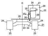
本実施形態において、排気口33は、図1,2に示すようにエンジンルーム28における上部旋回体22の旋回中心軸O側であって、上部旋回体22の横向き旋回状態でクローラ24の上面に対して内側に外れる位置で下面壁(アッパーフレーム26)に設けられ、この排気口33の上部に筒状のダクト36が設けられている。
Implementation form (see FIGS. 1 to 5)
In the present embodiment, the
このダクト36は、図示のように下端の出口側が排気口33に、上端の入口側がエンジンルーム28内にそれぞれ開口する状態で上下方向に設けられている。
As shown in the figure, the
排ガス管35は、中間部がダクト36に向かって折り曲げられ、その先端側部分(挿入部分)36aがダクト側壁を貫いてダクト36内に挿入されている。
The
すなわち、排ガス管35の先端側部分35aは、ダクト36と交差(望ましくは図示のように直交)してダクト36内をほぼ横断する状態で挿入されている。
That is, the front
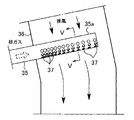
この排ガス管挿入部分35aには、図4,5に示すようにダクト36内を通る排風の風下側の半周部分(排風と直交する線より下側の半周部分)に、排ガスをダクト36内に噴射する複数の排出穴37が設けられている。 As shown in FIGS. 4 and 5, the exhaust gas pipe is inserted into the exhaust pipe 36 a into the half-circumferential part of the leeward side of the exhaust air passing through the duct 36 (the semi-circular part below the line perpendicular to the exhaust air). A plurality of discharge holes 37 for spraying into the inside are provided.
この排出穴37は、図示のように挿入部分35aの半周部分における周方向の複数個所に、かつ、挿入部分35aの長さ方向の複数個所にそれぞれ間隔を置いて設けられている。
As shown in the figure, the discharge holes 37 are provided at a plurality of locations in the circumferential direction of the half portion of the
また、この排出穴37…は、ここから排出される排ガス量が挿入部分35aの長さ方向にほぼ均等となるように、その開口面積が挿入部分35aの先端に向かって漸減する状態で設けられている。
Further, the discharge holes 37 are provided in a state in which the opening area gradually decreases toward the tip of the
具体的には、図4に示すように、排出穴37…の挿入部分長さ方向の間隔(密度)が挿入部分35aの先端に向かって漸次大きくなる(密度が疎になる)状態で設けられている。
Specifically, as shown in FIG. 4, the interval (density) in the insertion portion length direction of the discharge holes 37 is provided in a state of gradually increasing toward the tip of the
あるいは、排出穴37の大きさを先端に向かって漸次小さくしてもよい。
Or you may make the magnitude | size of the
なお、排出穴37は、図示の丸穴でもよいし、角穴でもよい。あるいは、挿入部分35aの長さ方向に長い溝穴としてもよい。溝穴とする場合は、その幅寸法を、先端に向かって漸次小さくすればよい。
The
また、本実施形態、及び後述する第1、第2両参考例において、排ガス管35の先端開口は閉塞され、または小開口面積に絞られる。
Further, in the present embodiment and first and second reference examples described later, the front end opening of the
本実施形態によると、排ガスと排風の混合気がエンジンルーム28から下向き、すなわち運転席と上下反対側に排出されるため、とくに実施形態で挙げた小型ショベルにおいてオペレータが受ける熱と騒音の悪影響を著しく低減することができる。
According to the present embodiment, since the mixture of exhaust gas and exhaust air is discharged downward from the
この場合、排気口33を、エンジンルーム28における上部旋回体22の旋回中心側であって、横向き旋回状態でクローラ24から内側に外れる位置で下向きに開口させているため、エンジンルーム28が片側クローラ上に位置する横向き旋回状態で、排出される混合気がクローラ24に直接かからない。
In this case, since the
このため、とくに小型ショベルに一般的に採用されているゴムクローラが混合気熱によって劣化し、耐久性が低下することを抑制することができる。 For this reason, it can suppress that the rubber crawler generally employ | adopted generally with a small shovel deteriorates by durability of mixed gas, and durability falls.
また、混合気を排気口33から直接排出するため、排気抵抗が少なくてすみ、排気の風量性能が良くなる。
Further, since the air-fuel mixture is directly discharged from the
さらに、本実施形態によると、排ガスが、図4,5に示すように挿入部分35aの風下側半周部分であってほぼ全長部分からダクト36内に、挿入部分35aの中心に対して放射状に噴射される。
Further, according to the present embodiment, the exhaust gas is injected radially from the almost full length portion into the
すなわち、排ガスが、
(i) ダクト36内の排風方向と異なる方向に、
(ii) 挿入部分35aの周方向及び長さ方向に分散して
噴射される。
That is, the exhaust gas
(i) In a direction different from the direction of exhaust air in the
(ii) The spray is dispersed in the circumferential direction and the length direction of the
この構成によると、第1に、上記(i)の異方向噴射作用により、圧力と流速が排風よりも高い排ガスがダクト断面の広い面積範囲に長くとどまるため、低圧、低速の排風と混ざり易くなる。 According to this configuration, firstly, due to the different direction injection action of (i) above, the exhaust gas whose pressure and flow velocity are higher than the exhaust air stays in a wide area range of the duct cross section, so it mixes with the low pressure and low speed exhaust air. It becomes easy.
第2に、上記(ii)の排ガスの周方向及び長さ方向拡散作用により、排ガスがダクト36内のさらに広い範囲で排風と混ざり合う。
Secondly, the exhaust gas is mixed with the exhaust air in a wider range in the
この二点の相乗効果により、排ガスと排風の混合効率を高め、排ガス温度を好ましい温度(たとえば500℃から100℃)まで確実に低下させた上でダクト36及び排気口33から外部に排出することができる。
Due to these two synergistic effects, the mixing efficiency of the exhaust gas and the exhaust air is increased, and the exhaust gas temperature is reliably lowered to a preferred temperature (for example, 500 ° C. to 100 ° C.) and then discharged from the
また、上記(i)(ii)の排ガス噴射作用によって排ガスの排出音(排気音)がダクト36の内面に接触し易くなること、及びエンジン7及び消音器14から発し排風に乗って外部に出ようとする音が排ガスとともにダクト16内で拡散・反射し易くなることにより、外部に排出される運転騒音を低減させることができる。
Further, the exhaust gas injection action (i) and (ii) makes it easy for the exhaust sound (exhaust sound) of the exhaust gas to come into contact with the inner surface of the
すなわち、排ガス温度低減効果及び騒音低減効果を公知技術よりも格段に高めることができる。 That is, the exhaust gas temperature reduction effect and the noise reduction effect can be remarkably enhanced as compared with known techniques.
なお、騒音低減効果をさらに向上させるためにダクト16の内面にグラスウール等の吸音材を設けるのが望ましい。
In order to further improve the noise reduction effect, it is desirable to provide a sound absorbing material such as glass wool on the inner surface of the
第1参考例(図6,7参照)
第1、第2両参考例については上記実施形態との相違点のみを説明する。
First reference example (see Figs. 6 and 7)
For the first and second reference examples , only differences from the above embodiment will be described.
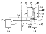
第1参考例においては、第1の相違点として、排気口33が、エンジンルーム28における旋回中心軸Oと反対側であって、上部旋回体22の横向き旋回状態で片側クローラ24の上面に対向する位置で下面壁(アッパーフレーム26)に設けられ、この排気口33の上部にダクト36が設けられるとともに、排気口33に風向部材としての風向板38が設けられている。
In the first reference example , the first difference is that the
この風向板38は、図7に拡大して示すように、混合気をクローラ上面から内側に外れる位置に向けて排出案内するための内向きに傾斜した複数の穴38a…を備え、この穴38a…によって混合気がクローラ24の上面よりも内側に排出案内される。
As shown in FIG. 7 in an enlarged manner, the
なお、風向部材として排気口33の外面(アッパーフレーム下面)に、傾斜した複数枚の風向板を設けてもよい。
A plurality of inclined wind direction plates may be provided on the outer surface (lower surface of the upper frame) of the
第2の相違点として、排ガス管35の先端側部分35aが、ダクト36の上方からダクト36内にまっすぐ下向きに挿入され、この挿入部分35aの長さ方向複数個所において全周部分に、排ガスを横向きに噴射する排出穴37…が間隔を置いて設けられている。
As a second difference, the
なお、この排出穴37…は、図では等径穴を長さ方向及び周方向に等間隔に設けているが、上記実施形態と同様に、排出される排ガス量が挿入部分35aの長さ方向にほぼ均等となるように、排出穴37…の長さ方向間隔(密度)が挿入部分35aの先端に向かって漸次大きくなる(密度が疎になる)状態で設けてもよいし、排出穴37…の大きさを先端に向かって漸次小さくしてもよい。
In the figure, the discharge holes 37 are provided with equal diameter holes at equal intervals in the length direction and the circumferential direction. However, as in the above embodiment, the amount of exhaust gas discharged is the length direction of the
この第1参考例によると、上記実施形態と同様に、混合気をクローラ上面から外れた位置に排出するため、熱によるゴムクローラの劣化を抑えることができるとともに、排気口33を設ける位置の自由度が高くなるため、機器レイアウトやダクトの形状、配置に関する設計、設置が容易となる。
According to the first reference example , as in the above embodiment, the air-fuel mixture is discharged to a position off the upper surface of the crawler, so that deterioration of the rubber crawler due to heat can be suppressed and the position where the
一方、排ガス管35の先端側部分35aをダクト36の上方から挿入しているため、先端側部分35aをダクト36の側壁に貫通させる必要も、そのための穴を設ける必要もなくなる。このため、排ガス管35及びダクト36の加工、設置が容易となる。
On the other hand, since the front
第2参考例
第2参考例においては、金属製クローラが用いられるショベルに適する構成として、第1参考例から風向板38を除去し、混合気が排気口33からそのまま下向き、すなわちクローラ24の上面に向けて排出される構成がとられている。他の構成は第1参考例と同じである。
Second reference example
In the second reference example , the
この構成によると、排気口33を設ける位置の自由度が高くなる点の利点を生かしながら、風向板38が不要となる分、構造が簡単ですむ。
According to this configuration, the structure can be simplified because the
なお、上記実施形態の、排気口33を、横向き旋回状態でクローラ上面から外れる位置でエンジンルーム下面壁に設ける構成と、第1、第2両参考例の、排ガス管先端側部分35aをダクト上方からまっすぐ挿入する構成を組み合わせてもよい。
In the above-described embodiment, the
また、上記実施形態の、排ガス管先端側部分35aをダクト側壁を貫通してダクト36内に挿入する構成と、排気口33を、横向き旋回状態でクローラ上面に対向する位置でエンジンルーム下面壁に設ける構成を組み合わせてもよい。
Further, in the above-described embodiment, the exhaust pipe distal
一方、本発明は油圧ショベルに限らず、エンジンルームを備え、冷却用空気と排ガスをこのエンジンルームから外部に排出する構成をとる他の建設機械にも上記同様に適用することができる。 On the other hand, the present invention is not limited to the hydraulic excavator, and can be similarly applied to other construction machines having an engine room and configured to discharge cooling air and exhaust gas from the engine room to the outside.
21 下部走行体
22 上部旋回体
O 旋回中心軸
23 下部走行体のカーボディ
24 同、クローラ
25 クローラ式走行装置
26 アッパーフレーム
27 エンジンガード部材
28 エンジンルーム
29 エンジン
32 吸気口
33 排気口
34 消音器
35 排ガス管
35a 排ガス管の先端側部分(挿入部分)
36 ダクト
37 排出穴
38 風向板
DESCRIPTION OF
36
Claims (7)
上記排気口及び上記ダクトの出口は、上記エンジンルームから下向きに開口し、
上記排ガス管の先端側部分は、上記ダクト内に挿入されていて、上記排ガスを上記ダクト内で上記排風と混合させて上記排気口から下向きに排出させるように構成され、
上記排気口は、上記エンジンルームにおける上記上部旋回体の旋回中心側の位置であって上記エンジンルームが左右片側の上記クローラ上に位置する上記上部旋回体の横向き旋回状態において上記左右片側のクローラの上面から上記下部走行体の内側に外れる位置で下向きに開口していることを特徴とする建設機械の排気構造。 A lower traveling body, provided with an upper rotating body mounted pivotally on its undercarriage, engine room provided in the upper rotating body, the engine room, the cooling air from the outside and an exhaust port for discharging exhaust air from the air inlet and the engine room is introduced into the engine room to the outside, the lower traveling body, the car body above the upper swing structure is mounted, the carbody attached to the right and left sides, in the construction machine having a crawler type traveling device having crawlers, ducts in the engine room is provided in communication with the exhaust port, the exhaust air of the engine room through the duct An exhaust structure for a construction machine configured to exhaust the exhaust gas of the engine to the outside through an exhaust gas pipe while discharging to the outside,
Outlet of the exhaust port and the duct is opened downward from the engine room,
The distal portion of the exhaust gas pipe is being inserted into the duct, the exhaust gas is mixed with the exhaust air in the duct is configured to make discharged downward from the exhaust port,
The exhaust port is a position on the turning center side of the upper swing body in the engine room, and the left and right crawlers of the upper swing body in the lateral swing state of the upper swing body in which the engine room is positioned on the left and right one side crawlers. An exhaust structure for a construction machine, wherein the exhaust structure is opened downward at a position deviating from the upper surface to the inside of the lower traveling body .
Priority Applications (6)
| Application Number | Priority Date | Filing Date | Title |
|---|---|---|---|
| JP2011157830A JP5886552B2 (en) | 2011-07-19 | 2011-07-19 | Exhaust structure of construction machinery |
| KR1020147003849A KR101610561B1 (en) | 2011-07-19 | 2012-07-11 | Construction machine |
| EP12815232.9A EP2735712B1 (en) | 2011-07-19 | 2012-07-11 | Construction machine |
| US14/233,322 US9027676B2 (en) | 2011-07-19 | 2012-07-11 | Construction machine |
| PCT/JP2012/004486 WO2013011666A1 (en) | 2011-07-19 | 2012-07-11 | Construction machine |
| CN201280035702.2A CN103688030B (en) | 2011-07-19 | 2012-07-11 | Engineering machinery |
Applications Claiming Priority (1)
| Application Number | Priority Date | Filing Date | Title |
|---|---|---|---|
| JP2011157830A JP5886552B2 (en) | 2011-07-19 | 2011-07-19 | Exhaust structure of construction machinery |
Publications (2)
| Publication Number | Publication Date |
|---|---|
| JP2013024078A JP2013024078A (en) | 2013-02-04 |
| JP5886552B2 true JP5886552B2 (en) | 2016-03-16 |
Family
ID=47557867
Family Applications (1)
| Application Number | Title | Priority Date | Filing Date |
|---|---|---|---|
| JP2011157830A Active JP5886552B2 (en) | 2011-07-19 | 2011-07-19 | Exhaust structure of construction machinery |
Country Status (6)
| Country | Link |
|---|---|
| US (1) | US9027676B2 (en) |
| EP (1) | EP2735712B1 (en) |
| JP (1) | JP5886552B2 (en) |
| KR (1) | KR101610561B1 (en) |
| CN (1) | CN103688030B (en) |
| WO (1) | WO2013011666A1 (en) |
Families Citing this family (22)
| Publication number | Priority date | Publication date | Assignee | Title |
|---|---|---|---|---|
| US9180891B2 (en) * | 2012-03-30 | 2015-11-10 | Electro-Motive Diesel, Inc. | HVAC system for heating and cooling a mobile machine cabin |
| JP2014163227A (en) * | 2013-02-21 | 2014-09-08 | Kobelco Contstruction Machinery Ltd | Exhaust structure of construction machine |
| JP6057808B2 (en) * | 2013-03-28 | 2017-01-11 | ヤンマー株式会社 | Engine equipment |
| US9662969B2 (en) | 2013-03-28 | 2017-05-30 | Yanmar Co., Ltd. | Engine device |
| JP5812038B2 (en) * | 2013-04-19 | 2015-11-11 | コベルコ建機株式会社 | Exhaust structure of construction machinery |
| JP5842887B2 (en) | 2013-09-19 | 2016-01-13 | コベルコ建機株式会社 | Work machine |
| JP5783216B2 (en) | 2013-10-15 | 2015-09-24 | コベルコ建機株式会社 | Exhaust structure of construction machinery |
| JP6268927B2 (en) * | 2013-10-30 | 2018-01-31 | コベルコ建機株式会社 | Exhaust structure of construction machinery |
| JP5850024B2 (en) * | 2013-10-31 | 2016-02-03 | コベルコ建機株式会社 | Work machine |
| JP5949730B2 (en) * | 2013-11-07 | 2016-07-13 | コベルコ建機株式会社 | Electrical equipment arrangement structure for construction machinery |
| US9302579B2 (en) * | 2014-05-20 | 2016-04-05 | Deere & Company | Flush mounted tractor exhaust outlet |
| US10377227B2 (en) * | 2014-08-21 | 2019-08-13 | Mitsubishi Logisnext Co., LTD. | Industrial vehicle |
| US10072900B2 (en) * | 2014-09-16 | 2018-09-11 | Mahle International Gmbh | Heat exchanger distributor with intersecting streams |
| EP4209860B1 (en) * | 2017-07-18 | 2024-05-22 | Kubota Corporation | Working machine |
| JP6664558B1 (en) * | 2019-02-04 | 2020-03-13 | 三菱電機株式会社 | Heat exchanger, air conditioner with heat exchanger, and refrigerant circuit with heat exchanger |
| NL1043254B1 (en) * | 2019-05-08 | 2020-11-30 | Rior Ind En Handelsonderneming B V | Service engine with exhaust cooling |
| JP7302365B2 (en) * | 2019-08-07 | 2023-07-04 | 株式会社豊田自動織機 | industrial vehicle |
| JP7373973B2 (en) * | 2019-11-18 | 2023-11-06 | 株式会社小松製作所 | working machine |
| JP7469962B2 (en) * | 2020-06-01 | 2024-04-17 | 日本車輌製造株式会社 | Construction Machinery |
| JP7585185B2 (en) | 2021-12-28 | 2024-11-18 | 株式会社クボタ | Work Machine |
| WO2022163304A1 (en) | 2021-01-27 | 2022-08-04 | 株式会社クボタ | Work machine |
| DE102022110879B3 (en) * | 2022-05-03 | 2023-03-02 | Liebherr-Werk Bischofshofen Gmbh | working machine |
Family Cites Families (20)
| Publication number | Priority date | Publication date | Assignee | Title |
|---|---|---|---|---|
| DE575150C (en) * | 1932-02-27 | 1933-04-25 | Humboldt Deutzmotoren Akt Ges | Cooling device for an internal combustion engine arranged on a support frame |
| JPH0337222U (en) * | 1989-08-23 | 1991-04-11 | ||
| JPH03229907A (en) | 1989-11-02 | 1991-10-11 | Komatsu Ltd | Engine intake and exhaust system built into the engine compartment |
| JPH07139369A (en) * | 1993-11-19 | 1995-05-30 | Mitsubishi Heavy Ind Ltd | Soundproofing/cooling/ventilating structure of enclosure |
| JPH11257045A (en) * | 1998-03-13 | 1999-09-21 | Hitachi Constr Mach Co Ltd | Exhaust device for construction machine |
| JP2001026944A (en) * | 1999-07-16 | 2001-01-30 | Kobelco Contstruction Machinery Ltd | Exhaust system structure for construction equipment |
| CN1201055C (en) * | 2000-12-01 | 2005-05-11 | 日立建机株式会社 | Construction machinery |
| JP2002174108A (en) * | 2000-12-07 | 2002-06-21 | Hitachi Constr Mach Co Ltd | Exhaust pipe structure of work vehicle |
| JP2002285858A (en) * | 2001-03-27 | 2002-10-03 | Asahi Denki Kk | Portable type or on-vehicle type power generator |
| JP2002317631A (en) * | 2001-04-23 | 2002-10-31 | Komatsu Ltd | Engine exhaust gas exhaust device |
| US6832872B2 (en) * | 2002-11-13 | 2004-12-21 | Blaw-Knox Construction Equipment Corporation | Gas discharge device for a construction vehicle |
| JP2004353461A (en) * | 2003-05-27 | 2004-12-16 | Nishishiba Electric Co Ltd | Package type power generator |
| JP2005264870A (en) * | 2004-03-19 | 2005-09-29 | Denyo Co Ltd | Soundproof engine driven work machine |
| JP4326479B2 (en) * | 2005-01-20 | 2009-09-09 | 本田技研工業株式会社 | Engine-driven work machine |
| JP4578336B2 (en) * | 2005-05-31 | 2010-11-10 | デンヨー株式会社 | Engine driven work machine |
| US8006489B2 (en) * | 2006-09-07 | 2011-08-30 | Volvo Group North America, Llc | Exhaust diffuser for a vocational truck |
| JP2009030559A (en) * | 2007-07-30 | 2009-02-12 | Caterpillar Japan Ltd | Exhaust structure in construction machine |
| JP5292534B2 (en) * | 2007-08-08 | 2013-09-18 | 日野自動車株式会社 | Exhaust purification device |
| JP5553562B2 (en) * | 2009-09-15 | 2014-07-16 | 日野自動車株式会社 | Exhaust purification device |
| JP2011106287A (en) * | 2009-11-12 | 2011-06-02 | Yanmar Co Ltd | Engine generator |
-
2011
- 2011-07-19 JP JP2011157830A patent/JP5886552B2/en active Active
-
2012
- 2012-07-11 KR KR1020147003849A patent/KR101610561B1/en not_active Expired - Fee Related
- 2012-07-11 CN CN201280035702.2A patent/CN103688030B/en not_active Expired - Fee Related
- 2012-07-11 US US14/233,322 patent/US9027676B2/en active Active
- 2012-07-11 WO PCT/JP2012/004486 patent/WO2013011666A1/en not_active Ceased
- 2012-07-11 EP EP12815232.9A patent/EP2735712B1/en not_active Not-in-force
Also Published As
| Publication number | Publication date |
|---|---|
| US9027676B2 (en) | 2015-05-12 |
| EP2735712A1 (en) | 2014-05-28 |
| EP2735712B1 (en) | 2016-04-06 |
| WO2013011666A1 (en) | 2013-01-24 |
| CN103688030A (en) | 2014-03-26 |
| KR101610561B1 (en) | 2016-04-07 |
| JP2013024078A (en) | 2013-02-04 |
| EP2735712A4 (en) | 2015-05-06 |
| CN103688030B (en) | 2016-01-27 |
| US20140144717A1 (en) | 2014-05-29 |
| KR20140048274A (en) | 2014-04-23 |
Similar Documents
| Publication | Publication Date | Title |
|---|---|---|
| JP5886552B2 (en) | Exhaust structure of construction machinery | |
| US9347202B2 (en) | Construction machine | |
| JP5699653B2 (en) | Construction machine cooling structure | |
| JP6530977B2 (en) | Air intake structure of construction machine | |
| JP2013039895A (en) | Cooler for construction machine | |
| EP2821608A1 (en) | Cooling structure for urea aqueous solution conduit | |
| WO2014065022A1 (en) | Ventilation structure for engine compartment | |
| WO2004113699A1 (en) | Construction machine engine hood, construction machine engine room construction, and construction machine cooling device | |
| JP5783216B2 (en) | Exhaust structure of construction machinery | |
| JP2012207490A (en) | Construction machine | |
| JP2002192960A (en) | Engine hood for construction machinery | |
| JP2009030559A (en) | Exhaust structure in construction machine | |
| US20140301839A1 (en) | Construction machine | |
| JP2017160639A (en) | Exhaust device for work machine | |
| JP2008155790A (en) | Work vehicle | |
| JP2004353539A (en) | Engine room structure and engine cooling device of construction machinery | |
| JPH11257045A (en) | Exhaust device for construction machine | |
| JP6700113B2 (en) | Engine equipment | |
| JP4983040B2 (en) | Wheeled work machine | |
| JP4436293B2 (en) | Sound absorption duct for construction machinery | |
| JP2005125951A (en) | Engine hood for construction machine, engine compartment for construction machine and cooling device for construction machine | |
| JP4777221B2 (en) | Engine room duct structure and construction machine having the same | |
| JP2011157796A (en) | Construction machine | |
| JP2011021449A (en) | Sound absorbing structure of engine room | |
| JP2005307489A (en) | Swing type work machine |
Legal Events
| Date | Code | Title | Description |
|---|---|---|---|
| A621 | Written request for application examination |
Free format text: JAPANESE INTERMEDIATE CODE: A621 Effective date: 20140611 |
|
| A131 | Notification of reasons for refusal |
Free format text: JAPANESE INTERMEDIATE CODE: A131 Effective date: 20150901 |
|
| A521 | Request for written amendment filed |
Free format text: JAPANESE INTERMEDIATE CODE: A523 Effective date: 20151102 |
|
| TRDD | Decision of grant or rejection written | ||
| A01 | Written decision to grant a patent or to grant a registration (utility model) |
Free format text: JAPANESE INTERMEDIATE CODE: A01 Effective date: 20160202 |
|
| A61 | First payment of annual fees (during grant procedure) |
Free format text: JAPANESE INTERMEDIATE CODE: A61 Effective date: 20160212 |
|
| R150 | Certificate of patent or registration of utility model |
Ref document number: 5886552 Country of ref document: JP Free format text: JAPANESE INTERMEDIATE CODE: R150 |
|
| R250 | Receipt of annual fees |
Free format text: JAPANESE INTERMEDIATE CODE: R250 |
|
| R250 | Receipt of annual fees |
Free format text: JAPANESE INTERMEDIATE CODE: R250 |
|
| R250 | Receipt of annual fees |
Free format text: JAPANESE INTERMEDIATE CODE: R250 |
|
| R250 | Receipt of annual fees |
Free format text: JAPANESE INTERMEDIATE CODE: R250 |
|
| R250 | Receipt of annual fees |
Free format text: JAPANESE INTERMEDIATE CODE: R250 |
|
| R250 | Receipt of annual fees |
Free format text: JAPANESE INTERMEDIATE CODE: R250 |