JP5884834B2 - Control device for internal combustion engine - Google Patents
Control device for internal combustion engine Download PDFInfo
- Publication number
- JP5884834B2 JP5884834B2 JP2013555065A JP2013555065A JP5884834B2 JP 5884834 B2 JP5884834 B2 JP 5884834B2 JP 2013555065 A JP2013555065 A JP 2013555065A JP 2013555065 A JP2013555065 A JP 2013555065A JP 5884834 B2 JP5884834 B2 JP 5884834B2
- Authority
- JP
- Japan
- Prior art keywords
- injection
- learning
- fuel
- amount
- executed
- Prior art date
- Legal status (The legal status is an assumption and is not a legal conclusion. Google has not performed a legal analysis and makes no representation as to the accuracy of the status listed.)
- Expired - Fee Related
Links
- 238000002485 combustion reaction Methods 0.000 title claims description 57
- 238000002347 injection Methods 0.000 claims description 523
- 239000007924 injection Substances 0.000 claims description 523
- 239000000446 fuel Substances 0.000 claims description 235
- 238000000520 microinjection Methods 0.000 claims description 36
- 230000009467 reduction Effects 0.000 claims description 2
- 238000000034 method Methods 0.000 description 15
- 230000007423 decrease Effects 0.000 description 14
- 239000007788 liquid Substances 0.000 description 12
- 230000006835 compression Effects 0.000 description 11
- 238000007906 compression Methods 0.000 description 11
- 238000012545 processing Methods 0.000 description 10
- 230000008859 change Effects 0.000 description 8
- 239000003054 catalyst Substances 0.000 description 6
- 238000012937 correction Methods 0.000 description 6
- 238000004891 communication Methods 0.000 description 5
- 238000010586 diagram Methods 0.000 description 5
- 230000008569 process Effects 0.000 description 5
- 230000004048 modification Effects 0.000 description 4
- 238000012986 modification Methods 0.000 description 4
- 230000003647 oxidation Effects 0.000 description 4
- 238000007254 oxidation reaction Methods 0.000 description 4
- 230000002093 peripheral effect Effects 0.000 description 3
- 238000011144 upstream manufacturing Methods 0.000 description 3
- 230000006872 improvement Effects 0.000 description 2
- 238000010792 warming Methods 0.000 description 2
- 230000033228 biological regulation Effects 0.000 description 1
- 230000003247 decreasing effect Effects 0.000 description 1
- 230000003111 delayed effect Effects 0.000 description 1
- 230000006866 deterioration Effects 0.000 description 1
- 230000000694 effects Effects 0.000 description 1
- 230000005284 excitation Effects 0.000 description 1
- 238000004519 manufacturing process Methods 0.000 description 1
- 230000001737 promoting effect Effects 0.000 description 1
- 239000000779 smoke Substances 0.000 description 1
- 239000004071 soot Substances 0.000 description 1
- 238000005507 spraying Methods 0.000 description 1
Images


Classifications
-
- F—MECHANICAL ENGINEERING; LIGHTING; HEATING; WEAPONS; BLASTING
- F02—COMBUSTION ENGINES; HOT-GAS OR COMBUSTION-PRODUCT ENGINE PLANTS
- F02D—CONTROLLING COMBUSTION ENGINES
- F02D41/00—Electrical control of supply of combustible mixture or its constituents
- F02D41/24—Electrical control of supply of combustible mixture or its constituents characterised by the use of digital means
- F02D41/2406—Electrical control of supply of combustible mixture or its constituents characterised by the use of digital means using essentially read only memories
- F02D41/2425—Particular ways of programming the data
- F02D41/2429—Methods of calibrating or learning
- F02D41/2441—Methods of calibrating or learning characterised by the learning conditions
-
- F—MECHANICAL ENGINEERING; LIGHTING; HEATING; WEAPONS; BLASTING
- F02—COMBUSTION ENGINES; HOT-GAS OR COMBUSTION-PRODUCT ENGINE PLANTS
- F02D—CONTROLLING COMBUSTION ENGINES
- F02D41/00—Electrical control of supply of combustible mixture or its constituents
- F02D41/24—Electrical control of supply of combustible mixture or its constituents characterised by the use of digital means
- F02D41/2406—Electrical control of supply of combustible mixture or its constituents characterised by the use of digital means using essentially read only memories
- F02D41/2425—Particular ways of programming the data
- F02D41/2429—Methods of calibrating or learning
- F02D41/2451—Methods of calibrating or learning characterised by what is learned or calibrated
- F02D41/2464—Characteristics of actuators
- F02D41/2467—Characteristics of actuators for injectors
-
- F—MECHANICAL ENGINEERING; LIGHTING; HEATING; WEAPONS; BLASTING
- F02—COMBUSTION ENGINES; HOT-GAS OR COMBUSTION-PRODUCT ENGINE PLANTS
- F02D—CONTROLLING COMBUSTION ENGINES
- F02D35/00—Controlling engines, dependent on conditions exterior or interior to engines, not otherwise provided for
- F02D35/02—Controlling engines, dependent on conditions exterior or interior to engines, not otherwise provided for on interior conditions
- F02D35/023—Controlling engines, dependent on conditions exterior or interior to engines, not otherwise provided for on interior conditions by determining the cylinder pressure
-
- F—MECHANICAL ENGINEERING; LIGHTING; HEATING; WEAPONS; BLASTING
- F02—COMBUSTION ENGINES; HOT-GAS OR COMBUSTION-PRODUCT ENGINE PLANTS
- F02D—CONTROLLING COMBUSTION ENGINES
- F02D41/00—Electrical control of supply of combustible mixture or its constituents
- F02D41/24—Electrical control of supply of combustible mixture or its constituents characterised by the use of digital means
- F02D41/2406—Electrical control of supply of combustible mixture or its constituents characterised by the use of digital means using essentially read only memories
- F02D41/2425—Particular ways of programming the data
- F02D41/2429—Methods of calibrating or learning
- F02D41/2451—Methods of calibrating or learning characterised by what is learned or calibrated
- F02D41/2464—Characteristics of actuators
- F02D41/2467—Characteristics of actuators for injectors
- F02D41/247—Behaviour for small quantities
-
- F—MECHANICAL ENGINEERING; LIGHTING; HEATING; WEAPONS; BLASTING
- F02—COMBUSTION ENGINES; HOT-GAS OR COMBUSTION-PRODUCT ENGINE PLANTS
- F02D—CONTROLLING COMBUSTION ENGINES
- F02D41/00—Electrical control of supply of combustible mixture or its constituents
- F02D41/30—Controlling fuel injection
- F02D41/38—Controlling fuel injection of the high pressure type
- F02D41/40—Controlling fuel injection of the high pressure type with means for controlling injection timing or duration
- F02D41/402—Multiple injections
-
- F—MECHANICAL ENGINEERING; LIGHTING; HEATING; WEAPONS; BLASTING
- F02—COMBUSTION ENGINES; HOT-GAS OR COMBUSTION-PRODUCT ENGINE PLANTS
- F02M—SUPPLYING COMBUSTION ENGINES IN GENERAL WITH COMBUSTIBLE MIXTURES OR CONSTITUENTS THEREOF
- F02M61/00—Fuel-injectors not provided for in groups F02M39/00 - F02M57/00 or F02M67/00
- F02M61/04—Fuel-injectors not provided for in groups F02M39/00 - F02M57/00 or F02M67/00 having valves, e.g. having a plurality of valves in series
- F02M61/10—Other injectors with elongated valve bodies, i.e. of needle-valve type
-
- F—MECHANICAL ENGINEERING; LIGHTING; HEATING; WEAPONS; BLASTING
- F02—COMBUSTION ENGINES; HOT-GAS OR COMBUSTION-PRODUCT ENGINE PLANTS
- F02M—SUPPLYING COMBUSTION ENGINES IN GENERAL WITH COMBUSTIBLE MIXTURES OR CONSTITUENTS THEREOF
- F02M61/00—Fuel-injectors not provided for in groups F02M39/00 - F02M57/00 or F02M67/00
- F02M61/16—Details not provided for in, or of interest apart from, the apparatus of groups F02M61/02 - F02M61/14
- F02M61/18—Injection nozzles, e.g. having valve seats; Details of valve member seated ends, not otherwise provided for
- F02M61/1806—Injection nozzles, e.g. having valve seats; Details of valve member seated ends, not otherwise provided for characterised by the arrangement of discharge orifices, e.g. orientation or size
-
- F—MECHANICAL ENGINEERING; LIGHTING; HEATING; WEAPONS; BLASTING
- F02—COMBUSTION ENGINES; HOT-GAS OR COMBUSTION-PRODUCT ENGINE PLANTS
- F02D—CONTROLLING COMBUSTION ENGINES
- F02D2200/00—Input parameters for engine control
- F02D2200/02—Input parameters for engine control the parameters being related to the engine
- F02D2200/10—Parameters related to the engine output, e.g. engine torque or engine speed
- F02D2200/101—Engine speed
-
- F—MECHANICAL ENGINEERING; LIGHTING; HEATING; WEAPONS; BLASTING
- F02—COMBUSTION ENGINES; HOT-GAS OR COMBUSTION-PRODUCT ENGINE PLANTS
- F02M—SUPPLYING COMBUSTION ENGINES IN GENERAL WITH COMBUSTIBLE MIXTURES OR CONSTITUENTS THEREOF
- F02M45/00—Fuel-injection apparatus characterised by having a cyclic delivery of specific time/pressure or time/quantity relationship
- F02M45/02—Fuel-injection apparatus characterised by having a cyclic delivery of specific time/pressure or time/quantity relationship with each cyclic delivery being separated into two or more parts
- F02M45/04—Fuel-injection apparatus characterised by having a cyclic delivery of specific time/pressure or time/quantity relationship with each cyclic delivery being separated into two or more parts with a small initial part, e.g. initial part for partial load and initial and main part for full load
-
- F—MECHANICAL ENGINEERING; LIGHTING; HEATING; WEAPONS; BLASTING
- F02—COMBUSTION ENGINES; HOT-GAS OR COMBUSTION-PRODUCT ENGINE PLANTS
- F02M—SUPPLYING COMBUSTION ENGINES IN GENERAL WITH COMBUSTIBLE MIXTURES OR CONSTITUENTS THEREOF
- F02M55/00—Fuel-injection apparatus characterised by their fuel conduits or their venting means; Arrangements of conduits between fuel tank and pump F02M37/00
- F02M55/02—Conduits between injection pumps and injectors, e.g. conduits between pump and common-rail or conduits between common-rail and injectors
- F02M55/025—Common rails
-
- Y—GENERAL TAGGING OF NEW TECHNOLOGICAL DEVELOPMENTS; GENERAL TAGGING OF CROSS-SECTIONAL TECHNOLOGIES SPANNING OVER SEVERAL SECTIONS OF THE IPC; TECHNICAL SUBJECTS COVERED BY FORMER USPC CROSS-REFERENCE ART COLLECTIONS [XRACs] AND DIGESTS
- Y02—TECHNOLOGIES OR APPLICATIONS FOR MITIGATION OR ADAPTATION AGAINST CLIMATE CHANGE
- Y02T—CLIMATE CHANGE MITIGATION TECHNOLOGIES RELATED TO TRANSPORTATION
- Y02T10/00—Road transport of goods or passengers
- Y02T10/10—Internal combustion engine [ICE] based vehicles
- Y02T10/40—Engine management systems
Landscapes
- Engineering & Computer Science (AREA)
- Chemical & Material Sciences (AREA)
- Combustion & Propulsion (AREA)
- Mechanical Engineering (AREA)
- General Engineering & Computer Science (AREA)
- Electrical Control Of Air Or Fuel Supplied To Internal-Combustion Engine (AREA)
- Combined Controls Of Internal Combustion Engines (AREA)
- Fuel-Injection Apparatus (AREA)
Description
この発明は、内燃機関の制御装置に係り、特に、筒内に燃料を直接噴射可能な燃料噴射弁を備える内燃機関の制御装置に関する。 The present invention relates to a control device for an internal combustion engine, and more particularly to a control device for an internal combustion engine including a fuel injection valve capable of directly injecting fuel into a cylinder.
従来、例えば特許文献1には、微小の燃料噴射量の学習制御を行う内燃機関の制御装置が開示されている。この微小噴射量の学習制御は、具体的には、減速時においてフューエルカットが行われる際に少量の燃料噴射を実施したうえで、この時の燃料噴射量と内燃機関の発生トルクとの関係に基づいて実行されるというものである。 Conventionally, for example, Patent Literature 1 discloses a control device for an internal combustion engine that performs learning control of a minute fuel injection amount. Specifically, the learning control of the minute injection amount is based on the relationship between the fuel injection amount at this time and the generated torque of the internal combustion engine after performing a small amount of fuel injection when fuel cut is performed during deceleration. It is executed based on.
ところで、内燃機関に用いられる燃料噴射弁として、次のような構成を備えるものが知られている。すなわち、先端部にシート当接部を有するニードル弁と、前記シート当接部が当接するシート部を有するノズルボディとを含む燃料噴射弁であって、かつ、当該ノズルボディが、シート部よりも下流側に形成された燃料溜まり部(いわゆるサックなどが該当)と、シート部よりも下流側に形成された少なくとも1つの噴孔とを備える燃料噴射弁が知られている。 By the way, what has the following structures is known as a fuel injection valve used for an internal combustion engine. That is, a fuel injection valve including a needle valve having a seat contact portion at a tip portion and a nozzle body having a seat portion with which the seat contact portion contacts, and the nozzle body is more than the seat portion. 2. Description of the Related Art There is known a fuel injection valve that includes a fuel reservoir portion (so-called sack or the like) formed on the downstream side and at least one injection hole formed on the downstream side of the seat portion.
上記構成を有する燃料噴射弁では、燃料溜まり部に充填された燃料量が多い状態(液密状態)と、燃料溜まり部に充填された燃料量が少ない状態(気密状態)とで、噴射量特性などの噴射特性が変化する。従って、上記構成を有する燃料噴射弁を備える内燃機関において特許文献1に記載の微小噴射量の学習制御を行った場合、燃料溜まり部の内部状態が液密状態であるか気密状態であるかによって、実際に噴孔から噴射される燃料噴射量が変動してしまう。その結果、燃料噴射量の学習精度が低下してしまうおそれがある。そして、このような課題は、上記学習制御のように微小な燃料噴射量についての学習制御を行う際において、より顕著となる。
尚、出願人は、本発明に関連するものとして、上記の文献を含めて、以下に記載する文献を認識している。In the fuel injection valve having the above-described configuration, the injection amount characteristic between a state where the amount of fuel filled in the fuel reservoir is large (liquid-tight state) and a state where the amount of fuel charged in the fuel reservoir is small (air-tight state). The injection characteristics such as change. Therefore, in the internal combustion engine including the fuel injection valve having the above-described configuration, when the learning control of the minute injection amount described in Patent Document 1 is performed, depending on whether the internal state of the fuel reservoir is a liquid-tight state or an air-tight state. The fuel injection amount actually injected from the nozzle hole will fluctuate. As a result, the learning accuracy of the fuel injection amount may be reduced. Such a problem becomes more conspicuous when performing learning control for a minute fuel injection amount as in the learning control described above.
The applicant has recognized the following documents including the above-mentioned documents as related to the present invention.
この発明は、上述のような課題を解決するためになされたもので、ニードル弁のシート当接部と当接するシート部よりも下流側に燃料溜まり部と少なくとも1つの噴孔を備えるノズルボディを有する燃料噴射弁が搭載された内燃機関において、運転中に実施される燃料噴射量の学習制御の精度を良好に向上させることのできる内燃機関の制御装置を提供することを目的とする。 The present invention has been made in order to solve the above-described problems. A nozzle body including a fuel reservoir portion and at least one injection hole downstream of a seat portion that contacts the seat contact portion of the needle valve is provided. An object of the present invention is to provide a control device for an internal combustion engine that can improve the accuracy of learning control of the fuel injection amount performed during operation in an internal combustion engine equipped with the fuel injection valve.
本発明は、先端部にシート当接部を有するニードル弁と、前記シート当接部が当接するシート部と、前記シート部よりも下流側に形成された燃料溜まり部と、前記シート部よりも下流側に形成された少なくとも1つの噴孔とを備えるノズルボディと、を含み、筒内に燃料を直接噴射可能な燃料噴射弁を備える内燃機関の制御装置であって、学習実行手段と学習前噴射実行手段とを備えている。
学習実行手段は、燃料噴射量を学習する燃料噴射量の学習制御を実行するものである。そして、学習前噴射実行手段は、前記学習制御のための燃料の学習用噴射の実施に先立って燃料の学習前噴射を実行するものである。前記学習前噴射は、前記燃料溜まり部を満たす燃料を噴射する充填用噴射である。前記充填用噴射により噴射される燃料の量は、前記学習用噴射により噴射される燃料の量以下である。
The present invention provides a needle valve having a seat abutting portion at a distal end portion, a seat portion with which the seat abutting portion abuts, a fuel reservoir portion formed on the downstream side of the seat portion, and the seat portion. A control device for an internal combustion engine comprising a fuel injection valve capable of directly injecting fuel into a cylinder, comprising: a nozzle body including at least one injection hole formed downstream; Injection execution means.
The learning execution means executes learning control of the fuel injection amount for learning the fuel injection amount. The pre-learning injection execution means executes fuel pre-learning injection prior to execution of fuel learning injection for the learning control. The pre-learning injection is a filling injection that injects fuel that fills the fuel reservoir. The amount of fuel injected by the filling injection is less than or equal to the amount of fuel injected by the learning injection.
本発明によれば、学習用噴射の実施に先立って学習前噴射を実行することにより、燃料溜まり部の内部を液密状態としたうえで、学習用噴射を実施できるようになる。これにより、噴孔から実際に噴射される燃料噴射量を安定させることができるので、燃料噴射量の学習制御による燃料噴射量の学習値のばらつきを抑制することができる。このため、燃料噴射量の学習精度を向上させることができる。さらに、本発明によれば、充填用噴射の利用により、燃料溜まり部の内部を確実に液密状態としたうえで、学習用噴射を実施できるようになる。これにより、燃料噴射量の学習精度を向上させることができる。 According to the present invention, the pre-learning injection is performed prior to the execution of the learning injection, so that the learning injection can be performed after the inside of the fuel reservoir is in a liquid-tight state. Thereby, since the fuel injection amount actually injected from the injection hole can be stabilized, variation in the learned value of the fuel injection amount due to the fuel injection amount learning control can be suppressed. For this reason, the learning accuracy of the fuel injection amount can be improved. Furthermore, according to the present invention, the injection for learning can be carried out by making sure that the inside of the fuel reservoir is in a liquid-tight state by using the injection for filling. Thereby, the learning accuracy of the fuel injection amount can be improved.
また、本発明における前記学習制御は、内燃機関の減速時において当該内燃機関のアイドル運転に必要となる燃料量よりも少ない量の燃料を前記学習用噴射として噴射し、前記学習用噴射を行った際の当該学習用噴射の量と前記内燃機関の回転変動との関係に基づいて行う微小噴射量の学習制御であってもよい。
これにより、燃料溜まり部の内部状態の変化によってより顕著に影響を受ける微小な燃料噴射量の学習制御を行う場合において、学習精度を向上させることができる。In the learning control according to the present invention, the learning injection is performed by injecting an amount of fuel smaller than that required for idle operation of the internal combustion engine as the learning injection during deceleration of the internal combustion engine. The learning control of the minute injection amount may be performed based on the relationship between the learning injection amount and the rotational fluctuation of the internal combustion engine.
Thereby, in the case of performing learning control of a minute fuel injection amount that is more significantly affected by a change in the internal state of the fuel reservoir, it is possible to improve learning accuracy.
また、本発明における前記学習実行手段は、前記充填用噴射を伴わずに前記学習用噴射が実行された際に当該学習用噴射により噴射される燃料噴射量についての第1学習パラメータを算出する第1学習パラメータ算出手段と、前記充填用噴射を伴って前記学習用噴射が実行された際に当該学習用噴射により噴射される燃料噴射量についての第2学習パラメータを算出する第2学習パラメータ算出手段と、前記第2学習パラメータと前記第1学習パラメータとの差分が所定値よりも小さい場合には、前記充填用噴射を伴わない前記学習用噴射が実行されるようにし、前記差分が前記所定値以上である場合には、前記充填用噴射を伴う前記学習用噴射が実行されるようにする噴射態様切替手段と、を含むものであってもよい。
これにより、上記差分の大きさに基づいて燃料溜まり部の内部状態を判定したうえで、学習値のばらつき(誤学習)の生ずる可能性があると判断できるときに限って、充填用噴射(学習前噴射)を伴う学習制御が実行されるようにすることができる。これにより、燃料溜まり部の内部状態が液密状態で安定している状況下において、不必要な充填用噴射が実行されるのを未然に防止することが可能となる。
Further, the learning execution means according to the present invention calculates a first learning parameter for a fuel injection amount injected by the learning injection when the learning injection is executed without the filling injection . 1 learning parameter calculation means and second learning parameter calculation means for calculating a second learning parameter for a fuel injection amount injected by the learning injection when the learning injection is executed with the filling injection When the difference between the second learning parameter and the first learning parameter is smaller than a predetermined value, the learning injection without the filling injection is executed, and the difference is the predetermined value. In the case of the above, it may include an injection mode switching means for executing the learning injection accompanied by the filling injection .
Thus, only when the internal state of the fuel reservoir is determined based on the magnitude of the difference and it can be determined that there is a possibility that a variation (learning) of the learning value may occur, the charging injection ( learning) can be made to the learning control with preinjection) is executed. This makes it possible to prevent unnecessary filling injection from being performed in a situation where the internal state of the fuel reservoir is stable in a liquid-tight state.
また、本発明は、前記燃料噴射弁を用いて、前記内燃機関のトルク発生のためのメイン噴射に加え、噴射される燃料が着火可能な時期において同じ燃料噴射量の指令値で実行される2回の微小噴射を実行するマルチ噴射実行手段を更に備えるものであってもよい。そして、前記学習前噴射実行手段は、前回のサイクルにおいて前記微小噴射としてのポスト噴射が実行されない場合に、1回目の前記微小噴射を前記充填用噴射として利用するものであってもよい。そして、前記学習実行手段は、1回目の前記微小噴射により噴射された燃料噴射量についての学習パラメータを前記第1学習パラメータとして使用し、2回目の前記微小噴射により噴射された燃料噴射量についての学習パラメータを前記第2学習パラメータとして使用するものであってもよい。
これにより、マルチ噴射に含まれる所定の微小噴射を利用して、燃料溜まり部の内部状態を判定することができる。
In addition to the main injection for generating the torque of the internal combustion engine, the present invention is executed with the same fuel injection amount command value at the time when the injected fuel can be ignited. Multi-injection execution means for executing the minute micro-injection may be further provided. Then, the learning before injection execution means, if the post injection as the small injection in the preceding cycle is not executed, may be configured to use the first of the small injection as the filling injection. Then, the learning execution means uses a learning parameter for the fuel injection amount injected by the first micro injection as the first learning parameter, and uses the learning parameter for the fuel injection amount injected by the second micro injection. A learning parameter may be used as the second learning parameter.
Thereby, the internal state of the fuel reservoir can be determined using a predetermined minute injection included in the multi-injection.
また、本発明は、前記燃料噴射弁を用いて、前記内燃機関のトルク発生のためのメイン噴射に加え、1サイクル中に1または複数回の微小噴射を実行するマルチ噴射実行手段を更に備えるものであってもよい。
そして、前記学習実行手段は、前記充填用噴射を伴わずに前記学習用噴射が実行された際に、当該学習用噴射により噴射された燃料噴射量の推定値を当該学習用噴射のための燃料噴射量の指令値と一致させるための第1学習値を算出する第1学習実行手段と、前記充填用噴射を伴って前記学習用噴射が実行された際に、当該学習用噴射により噴射された燃料噴射量の推定値を当該学習用噴射のための燃料噴射量の指令値と一致させるための第2学習値を算出する第2学習実行手段と、筒内圧力の低下率が高い膨張行程中の所定期間の経過後に最初に実行される前記微小噴射に対しては前記第1学習値を用い、前記所定期間の経過後に2回目以降において前記微小噴射が実行される場合には、当該2回目以降の前記微小噴射に対しては前記第2学習値を用いるように学習値を選択する学習値選択手段と、を含むものであってもよい。
このように、噴射順序に応じて学習値を使い分けることにより、学習実行時の燃料溜まり部の内部状態と実際の微小噴射の実行時の燃料溜まり部の内部状態とを合わせた状態で、微小噴射に対して適切な学習値を反映させられるようになる。これにより、微小噴射によって噴射される燃料量を精度良く制御することができる。
In addition to the main injection for generating the torque of the internal combustion engine, the present invention further includes a multi-injection executing means for executing one or a plurality of micro injections in one cycle using the fuel injection valve. It may be.
When the learning injection is executed without the charging injection , the learning execution means calculates an estimated value of the fuel injection amount injected by the learning injection as a fuel for the learning injection. First learning execution means for calculating a first learning value for matching with the command value of the injection amount, and when the learning injection is executed with the filling injection , the first injection is injected by the learning injection. A second learning execution means for calculating a second learning value for making the estimated value of the fuel injection amount coincide with the command value of the fuel injection amount for the learning injection; and during an expansion stroke in which the reduction rate of the in-cylinder pressure is high The first learning value is used for the first microinjection that is first executed after the elapse of the predetermined period, and the second injection is performed when the microinjection is executed for the second time and thereafter after the elapse of the predetermined period. For the subsequent micro-injection, the second A learning value selection means for selecting the learning value to use the 習値, it may include a.
In this way, by using the learning values properly according to the injection order, the microinjection is performed in a state where the internal state of the fuel reservoir at the time of learning execution and the internal state of the fuel reservoir at the time of actual microinjection are combined. It is possible to reflect an appropriate learning value for. Thereby, the fuel amount injected by micro injection can be controlled with high accuracy.
また、本発明における前記充填用噴射は、前記学習用噴射の実施に先立って、当該学習用噴射の実施を予定するサイクルの1つ前のサイクルにおける膨張行程中に筒内圧力が安定した時から、前記学習用噴射の実施を予定するサイクルにおいて当該学習用噴射の実施時期よりも所定時期早い時までの期間中に実行されるものであってもよい。
これにより、充填用噴射の実施後に燃料溜まり部が気密状態となるのを確実に防止することができる。
Further, the filling injection in the present invention is performed when the in-cylinder pressure is stabilized during the expansion stroke in the cycle immediately before the cycle in which the learning injection is scheduled to be performed prior to the execution of the learning injection. In the cycle in which the learning injection is scheduled to be performed, it may be executed during a period up to a predetermined time earlier than the learning injection execution time.
As a result, it is possible to reliably prevent the fuel reservoir from becoming airtight after the filling injection .
実施の形態1.
[内燃機関のシステム構成]
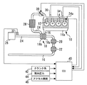
図1は、本発明の実施の形態1の内燃機関10のシステム構成を説明するための図である。図1に示すシステムは、内燃機関10を備えている。ここでは、内燃機関10は、4サイクルのディーゼルエンジン(圧縮着火式内燃機関)10であり、車両に搭載され、その動力源とされているものとする。本実施形態の内燃機関10は、直列4気筒型であるが、本発明における内燃機関の気筒数および気筒配置はこれに限定されるものではない。Embodiment 1 FIG.
[System configuration of internal combustion engine]
FIG. 1 is a diagram for explaining a system configuration of an
内燃機関10の各気筒には、燃料を筒内に直接噴射するための燃料噴射弁12が設置されている。燃料噴射弁12の噴射部の詳細な構成の一例については、図2を参照して後述する。各気筒の燃料噴射弁12は、共通のコモンレール14に接続されている。コモンレール14内には、サプライポンプ(図示省略)によって加圧された高圧の燃料が供給されている。そして、このコモンレール14から各気筒の燃料噴射弁12へ燃料が供給される。各気筒から排出される排気ガスは、排気マニホールド16aによって集合され、排気通路16に流入する。
Each cylinder of the
内燃機関10は、ターボ過給機18を備えている。ターボ過給機18は、排気ガスの排気エネルギによって作動するタービン18aと、連結軸を介してタービン18aと一体的に連結され、タービン18aに入力される排気ガスの排気エネルギによって回転駆動されるコンプレッサ18bとを有している。ターボ過給機18のタービン18aは、排気通路16の途中に配置されている。タービン18aよりも下流側の排気通路16には、排気ガスを浄化するために、酸化触媒20およびDPF(Diesel Particulate Filter)22が上流側から順に設置されている。
The
内燃機関10の吸気通路24の入口付近には、エアクリーナ26が設けられている。エアクリーナ26を通って吸入された空気は、ターボ過給機18のコンプレッサ18bで圧縮された後、インタークーラ28で冷却される。インタークーラ28を通過した吸入空気は、吸気マニホールド24aにより分配されて、各気筒に流入する。吸気通路24におけるインタークーラ28と吸気マニホールド24aとの間には、吸気絞り弁30が設置されている。
An
吸気通路24におけるエアクリーナ26の下流近傍には、吸入空気量を検出するためのエアフローメータ32が設置されている。コモンレール14には、コモンレール14内の燃料圧力を検出するためのコモンレール圧センサ34が設置されている。また、吸気マニホールド24aには、吸気マニホールド圧力(過給圧)を検出するための吸気圧力センサ36が設置されている。
An air flow meter 32 for detecting the amount of intake air is installed in the
更に、本実施形態のシステムは、ECU(Electronic Control Unit)40を備えている。ECU40の入力部には、上述したエアフローメータ32、コモンレール圧センサ34および吸気圧力センサ36に加え、エンジン回転数を検出するためのクランク角センサ42、および、筒内圧力を検出するための筒内圧センサ44等の内燃機関10の運転状態を検出するための各種センサが接続されている。また、ECU40には、内燃機関10を搭載する車両のアクセルペダルの踏み込み量(アクセル開度)を検出するためのアクセル開度センサ46が接続されている。更に、ECU40の出力部には、上述した燃料噴射弁12および吸気絞り弁30等の内燃機関10の運転を制御するための各種のアクチュエータが接続されている。ECU40は、それらのセンサ出力に基づいて、所定のプログラムに従って上記各種のアクチュエータを駆動することにより、内燃機関10の運転状態を制御するものである。
Furthermore, the system of the present embodiment includes an ECU (Electronic Control Unit) 40. In addition to the air flow meter 32, the common rail pressure sensor 34 and the
図2は、図1に示す燃料噴射弁12において燃料噴射が行われる側の先端部の構成を表した断面図である。
図2に示すように、燃料噴射弁12は、ノズルボディ12aを備えている。ノズルボディ12aの内部には、円錐状の先端部を有するニードル弁12bが往復移動自在に配置されている。ノズルボディ12aの内周面とニードル弁12bの外周面との間には、燃料が流通する内部燃料通路12cが形成されている。内部燃料通路12cには、図2における内部燃料通路12cの上方側から高圧の燃料が供給されるようになっている。FIG. 2 is a cross-sectional view showing the configuration of the tip portion on the side where fuel injection is performed in the
As shown in FIG. 2, the
ニードル弁12bの円錐状の先端部付近のノズルボディ12aの内周面には、ニードル弁12bのシート当接部12b1が着座可能なシート部12a1が形成されている。より具体的には、ニードル弁12bは、燃料噴射弁12が備える電磁石(図示省略)が磁力を発していない場合には、シート部12a1に着座するように構成されている。この場合には、シート部12a1の下流側に向けての燃料の流れが遮断される。一方、ニードル弁12bは、励磁電流の供給を受けて電磁石が磁力を発した場合には、シート部12a1から離座するように構成されている。その結果、シート部12a1の上流に蓄えられていた高圧の燃料がシート部12a1の下流側に供給される。
A seat portion 12a1 on which the seat contact portion 12b1 of the
また、ノズルボディ12aにおけるシート部12a1よりも下流側には、図2に示すように、燃料溜まり部(以下、「サック」とも称する)12dおよび複数の噴孔(図2においてそのうちの2つが図示)12eがそれぞれ形成されている。サック12dは、ニードル弁12bの開弁時に上流側から燃料が供給されることによって燃料が溜まり得る部位である。噴孔12eは、このようなサック12dとシート部12a1との間においてノズルボディ12aに形成されている。尚、複数の噴孔12eは、燃料噴射弁12の中心軸線を中心として、放射状に燃料が噴射できるように所定の角度間隔をおいて設置されている。
Further, on the downstream side of the seat portion 12a1 in the
更に、ニードル弁12bの先端部の一部は、図2に示すようにニードル弁12bがシート部12a1に着座した状態(閉弁状態)において、噴孔12eよりもサック12d側のノズルボディ12aの壁面12fと接触するように構成されている。これにより、ニードル弁12bがシート部12a1に着座した状態では、サック12dと各噴孔12eとの連通についても遮断されることになる。すなわち、本実施形態の燃料噴射弁12は、いわゆるVCO(Valve Covered Orifice)型の燃料噴射弁である。
Furthermore, a part of the tip of the
[微小噴射量の学習制御]
排気ガス規制が強化される中、パイロット噴射等の微小量での燃料噴射への要求精度が高まってきた。そこで、本実施形態の内燃機関10では、燃料噴射弁の個体差や経時劣化による微小噴射量の変化を補正するために、運転中に微小噴射量の学習制御を行うようにしている。[Learning control of minute injection amount]
As exhaust gas regulations are tightened, the required accuracy for fuel injection in minute quantities such as pilot injection has increased. Therefore, in the
具体的には、本学習制御では、減速時におけるフューエルカットの実行中にエンジン回転数が所定値に下がった時に、1気筒ずつ順に所定の微小な噴射量での燃料噴射が実行される。この燃料噴射は、燃焼が可能なタイミング(例えば、圧縮上死点近傍)において実行される。この微小な噴射量は、アイドル運転に必要となる燃料量よりも少ない量である。本学習制御では、このような噴射量での燃料噴射に伴うエンジン回転数の変動ΔNeを計測し、当該回転数変動ΔNeを生じさせるトルクに相当する推定噴射量Qvが算出される。そして、この推定噴射量Qvと、燃料噴射弁12に対して指令される噴射量との差を無くすために必要な燃料噴射量の補正量が学習値として算出され、ECU40に記憶される。そして、パイロット噴射等の微小噴射が実行される時に、上記補正量(学習値)に基づく補正後の噴射量で燃料噴射が行われるようにする。このようにして、微小噴射量の学習制御が実行される。
Specifically, in the present learning control, when the engine speed decreases to a predetermined value during execution of fuel cut at the time of deceleration, fuel injection with a predetermined minute injection amount is sequentially performed for each cylinder. This fuel injection is executed at a timing at which combustion is possible (for example, near the compression top dead center). This minute injection amount is an amount smaller than the amount of fuel required for idle operation. In the present learning control, the engine speed fluctuation ΔNe accompanying the fuel injection at such an injection quantity is measured, and the estimated injection quantity Qv corresponding to the torque that causes the engine speed fluctuation ΔNe is calculated. Then, the correction amount of the fuel injection amount necessary to eliminate the difference between the estimated injection amount Qv and the injection amount commanded to the
[実施の形態1における課題]
上述したように、VCO型の燃料噴射弁12では、ニードル弁12bのリフト終了時に、ニードル弁12bがシート部12a1に着座することによって内部燃料通路12cからの燃料供給が遮断されるとともに、ニードル弁12bの先端部が壁面12fと接触することによってサック12dと噴孔12eとの連通も遮断される。このため、閉弁中のサック12dの内部は、基本的には、液体で満たされた状態(以下、「液密状態」と称する)となることが予定されている。[Problems in Embodiment 1]
As described above, in the VCO type
しかしながら、燃料噴射弁12が新品状態である時には、ニードル弁12bとノズルボディ12aとの接触において機械的な馴染み(摺り合わせ)がとれていない。また、ニードル弁12bは、一般的に、ノズルボディ12aの内部において回転方向の変位は規制されていないため、リフト動作を行う毎にノズルボディ12aに対するニードル弁12bの回転位置が変化し得る。このような背景によって、新品状態においては、ニードル弁12bがシート部12a1に着座した際に、上記回転位置次第でニードル弁12bの先端部と壁面12fとの間に隙間が生じ、サック12dと噴孔12eとの連通が遮断されなくなることがある。
However, when the
また、燃料噴射弁12からは、何十から何百MPaという高圧の燃料が勢い良く噴射される。このため、上記隙間が生じているような場合には、ニードル弁12bがシート部12a1に着座した後においても、サック12d内の燃料の一部が慣性によって上記隙間を介して外部に出て行こうとする。その結果、実際にサック12dから出て行った燃料と入れ替わりでガスがサック12dに浸入し、サック12d内に気泡が生じ得る。
Further, from the
上記のようにサック12d内に気泡が生じている状況下において膨張行程が到来し、筒内圧力(すなわち、噴孔12eの外側の圧力)が低下していくと、サック12d内のガスが膨張する。その結果、膨張したガスによってサック12dの燃料が押し出されると、サック12dの内部が気体で満たされた状態(以下、「気密状態」と称する)となる。
As described above, when the expansion stroke comes under the condition where bubbles are generated in the
尚、本明細書中においては、サック12dの内部状態を分かり易く表現するために、上記のように定義された「液密状態」および「気密状態」という用語を使用する。ただし、本明細書でいう「液密状態」とは、サック12dの内部が厳密に100%液体で満たされた状態のみを指すものではなく、同様に、「気密状態」とは、サック12dの内部が厳密に100%気体で満たされた状態のみを指すものではない。すなわち、本明細書中においては、サック12dの内部に気泡の存在が認められるが大まかに見て液体で満たされているような状態をも想定して(対象として)「液密状態」と称し、同様に、サック12dの内部に液体の存在が認められるが大まかに見て気体で満たされているような状態をも想定して(対象として)「気密状態」と称している。つまり、本明細書における「液密状態」および「気密状態」という用語は、サック12dの内部に充填された燃料量が相対的に多い状態と少ない状態を区別するためにそれぞれ使用されるものである。
In the present specification, in order to express the internal state of the
図3は、サック12dの内部が液密状態である場合と気密状態である場合との間で、噴孔12eから噴射される燃料噴射量を比較して表した図である。また、図4は、サック12dの内部が液密状態である場合と気密状態である場合との間で、ニードル弁12bのリフト量を比較して表した図である。尚、図3および図4は、微小噴射を行った際のデータである。
FIG. 3 is a diagram comparing the fuel injection amounts injected from the nozzle holes 12e between the case where the inside of the
気密状態である時に微小噴射を行った場合には、液密状態である時に同様の噴射を行った場合と比べ、図3に示すように、噴孔12eから実際に噴射される燃料量が減少する。その理由の1つは、気密状態である時ではサック12d内への補充のために燃料が消費されるためである。また、更なる理由として、気密状態である時には、サック12d内の燃料によるニードル弁12bの押上げ力の低下によって、図4に示すように、液密状態である時と比べ、ニードル弁12bのリフト量が低下することが挙げられる。尚、ここでは、燃料噴射量の変化を例に挙げたが、燃料噴射開始時のサック12dの内部状態が液密状態であるか気密状態であるかの違いによって、燃料噴射量以外の噴射量特性や噴霧も大きく変化する。
When the minute injection is performed in the airtight state, the amount of fuel actually injected from the
また、上述したように、燃料噴射弁12が新品状態である時には、リフト動作を行う毎にノズルボディ12aに対するニードル弁12bの回転位置が変化し得る。このため、新品状態においては、上記回転位置次第で上記隙間が生ずることとなる。その結果、燃料噴射の開始時のサック12dの内部状態が液密状態と気密状態との間で変化するという現象が生ずることとなる。微小噴射量の学習制御の実行時に上記の現象が生ずると、実際に噴孔12eから噴射される燃料噴射量が変動してしまう。その結果、学習結果にばらつきが生じ得ることとなる、すなわち、誤学習が生じ得ることとなる。
Further, as described above, when the
[実施の形態1における特徴的な制御]
そこで、本実施形態では、微小噴射量の学習制御のための微小噴射(学習用噴射)の実施に先立って、サック12dの内部が液密状態となるように燃料を充填するための充填用噴射(学習前噴射)を実施するようにした。具体的には、この場合の充填用の燃料噴射量は、微小噴射量の学習制御の妨げにならないようにしつつサック12d内に燃料を充填するだけの超微小量(例えば、1mm3/st以下)でよい。また、この燃料噴射量は、例えば、サック12dの容積相当量としてもよい。[Characteristic Control in Embodiment 1]
Therefore, in the present embodiment, prior to the execution of the minute injection (learning injection) for learning control of the minute injection amount, the filling injection for filling the fuel so that the inside of the
図5は、学習用噴射と充填用噴射(学習前噴射)の実施時期を説明するための図である。
図5中に「従来」と付して示すように充填用噴射が行われない場合には、学習用噴射は、一般的に、圧縮上死点直前の所定タイミングにて行われる。一方、本実施形態の充填用噴射は、サック12dに充填した燃料が流出してサック12dの内部が気密状態とならないようにするために、充填用噴射を行った後に学習用噴射が始まる前に筒内圧力が低下しない時期とされている。FIG. 5 is a diagram for explaining the execution timing of the learning injection and the filling injection (pre-learning injection).
When the filling injection is not performed as indicated by “conventional” in FIG. 5, the learning injection is generally performed at a predetermined timing immediately before the compression top dead center. On the other hand, the filling injection of the present embodiment is performed before the learning injection starts after the filling injection is performed in order to prevent the fuel filled in the
具体的には、学習用噴射と同一サイクルにおいて充填用噴射を行う場合であれば、充填用噴射の実施時期は、図5に示すように、吸気行程および圧縮行程中の所望の時期とされる。ただし、この場合の学習用噴射は、充填用噴射による影響を受けないようにするために、充填用噴射の実施から所定間隔(例えば、90°CA程度)を経過した後に行われるようにする。充填用噴射による上記影響としては、充填用噴射の実施に伴う、エンジン回転数の変動およびコモンレール14内の燃料の圧力変動が考えられる。このため、上記影響が収束するまで、学習用噴射を待機させるようにする。充填用噴射が圧縮行程にて実施された場合には、この充填用噴射による燃焼が圧縮上死点付近で発生する可能性がある。このため、このような場合には、図5中の「例1」で示すように、学習用噴射の実施時期を通常よりも遅角するようにする。 Specifically, when the filling injection is performed in the same cycle as the learning injection, the filling injection is performed at a desired time during the intake stroke and the compression stroke, as shown in FIG. . However, in this case, the learning injection is performed after a predetermined interval (for example, about 90 ° CA) has passed since the filling injection is performed so as not to be affected by the filling injection. As the above-mentioned influence due to the injection for filling, the fluctuation of the engine speed and the pressure fluctuation of the fuel in the common rail 14 due to the implementation of the filling injection can be considered. For this reason, the injection for learning is made to wait until the said effect converges. When the filling injection is performed in the compression stroke, the combustion by the filling injection may occur near the compression top dead center. For this reason, in such a case, as shown in “Example 1” in FIG. 5, the execution timing of the learning injection is delayed more than usual.
また、学習用噴射を行うサイクルの1つ前のサイクルにおいて充填用噴射を行う場合であれば、充填用噴射の実施時期は、充填用噴射後に筒内圧力が低下していく期間(膨張行程の前期)を避け、筒内圧力の低下が収まって安定した後の時期(すなわち、膨張行程後期および排気行程)とされる。 Further, if the injection for filling is performed in the cycle immediately before the cycle for performing the learning injection, the timing of performing the injection for filling is the period during which the in-cylinder pressure decreases after the injection for filling (in the expansion stroke). The first period is avoided, and the period after the drop in the in-cylinder pressure is settled and stabilized (that is, the latter stage of the expansion stroke and the exhaust stroke).
以上のような手順で学習用噴射に先行する充填用噴射の実施時期を設定することによって充填用噴射と学習用噴射との間に膨張行程の前期を介在させないことで、サック12dの内部を確実に液密状態としたうえで、学習用噴射を実施できるようになる。
By setting the execution timing of the filling injection preceding the learning injection in the above-described procedure, the inside of the
図6は、本発明の実施の形態1における微小噴射量の学習制御を実現するために、本実施の形態1においてECU40が実行するルーチンを示すフローチャートである。尚、本ルーチンは、フューエルカットが実行される減速時にエンジン回転数が所定値以下に低下した時に起動されるものとする。
FIG. 6 is a flowchart showing a routine executed by the
図6に示すルーチンでは、先ず、クランク角センサ42を利用して、膨張行程(前期)ではないか否かが判定される(ステップ100)。既述したように、膨張行程の特に前期においては、筒内圧力が低下していく。ECU40には、そのような筒内圧力の低下が生ずるクランク角期間が予め記憶されている。本ステップ100では、現在のクランク角度が上記クランク角期間内に位置していないかどうかが判定される。
In the routine shown in FIG. 6, first, it is determined using the
上記ステップ100の判定が成立した場合には、充填用噴射が実行される(ステップ102)。具体的には、学習用噴射と同一サイクルにおいて行う場合であれば、充填用噴射は、吸気行程の開始から圧縮行程の終了までの期間中の所定の時期において実施される。また、学習用噴射の1つ前のサイクルにおいて行う場合であれば、充填用噴射は、上記クランク角期間の経過後の膨張行程から排気行程の終了までの期間中の所定の時期において実施される。
When the determination in
次に、上記ステップ102において実施された充填用噴射からの所定期間(例えば、90°CA)が少なくとも確保されるように、学習用噴射を待機する処理が実行される(ステップ104)。次いで、燃焼が可能な所定の実施時期において学習用噴射が実行される(ステップ106)。
Next, a process of waiting for the learning injection is performed so that at least a predetermined period (for example, 90 ° CA) from the filling injection performed in
次に、学習用噴射の実施に伴うエンジン回転数の変動ΔNeが計測される(ステップ108)。次いで、計測された回転数変動ΔNeを生じさせるトルクに相当する推定噴射量Qvが算出される(ステップ110)。次いで、微小噴射量の学習処理が実行される(ステップ112)。具体的には、算出された推定噴射量Qvと、上記ステップ106において実行された学習用噴射の指令値との差を無くすために必要な燃料噴射量の補正量(学習値)が算出され、ECU40に記憶される。尚、このように算出された補正量は、パイロット噴射等の微小噴射が今後実行される時に使用される。
Next, the engine speed fluctuation ΔNe accompanying the learning injection is measured (step 108). Next, an estimated injection amount Qv corresponding to the torque that causes the measured rotation speed fluctuation ΔNe is calculated (step 110). Next, a learning process of the minute injection amount is executed (step 112). Specifically, a fuel injection amount correction amount (learning value) necessary to eliminate the difference between the calculated estimated injection amount Qv and the learning injection command value executed in
以上説明した図6に示すルーチンによれば、学習用噴射の実施に先立って、サック12dに燃料を充填するための充填用噴射(学習前噴射)が実行される。その結果、サック12dの内部を確実に液密状態としたうえで、学習用噴射を実施できるようになる。これにより、噴孔12eから実際に噴射される燃料噴射量を安定させることができるので、微小噴射量の学習制御による微小噴射量の学習値のばらつきを抑制することができる。このため、微小噴射量の学習精度を向上させることができる。更に付け加えると、サック12dの内部状態が液密状態であるか気密状態であるかの違いによる燃料噴射量の学習値のばらつきの影響は、本実施形態で行われるような微小噴射(パイロット噴射など)のための学習制御が行われる場合において、より顕著となる。つまり、学習用噴射の実施に先立つ充填用噴射の実施は、微小な噴射量の学習精度の向上を簡便な構成で実現する手法として極めて有効なものである。
According to the routine shown in FIG. 6 described above, the filling injection (pre-learning injection) for filling the
また、上記ルーチンによれば、膨張行程の前期、すなわち、筒内圧力が低下していく期間を避けつつ、充填用噴射が実行される。これにより、充填用噴射の実施によって確実な液密状態が得られたサック12dの内部が、学習用噴射が実行されるまでの間に気密状態に変化するのを防止することができる。
Further, according to the above routine, the filling injection is executed while avoiding the first half of the expansion stroke, that is, the period during which the in-cylinder pressure decreases. As a result, it is possible to prevent the inside of the
ところで、上述した実施の形態1においては、VCO型の燃料噴射弁12(図2参照)を例に挙げて、本実施形態の制御について説明を行った。このようなVCO型の燃料噴射弁12においては、既述したように、特に新品状態では、シート部12a1に対する着座時のニードル弁12bの回転位置次第で、ニードル弁12bの先端部と壁面12fとの間に隙間が生じ得る。その結果、燃料噴射の開始時のサック12dの内部状態が液密状態と気密状態との間で変化するという現象が生ずる。このため、本実施形態の充填用噴射を事前に実施しておかないと、微小噴射量の学習制御において学習ばらつきが生じ得る。しかしながら、本発明の対象となる燃料噴射弁の構成は、上述したVCO型のものに限られない。
By the way, in Embodiment 1 mentioned above, the control of this embodiment was demonstrated taking the VCO type fuel injection valve 12 (refer FIG. 2) as an example. In such a VCO type
すなわち、本発明の対象となる燃料噴射弁は、ニードル弁のシート当接部と当接するシート部の下流側に燃料溜まり部と少なくとも1つの噴孔とを備えるノズルボディを含むものであればよい。例えば、VCO型のように噴孔と燃料溜まり部(サック)との連通を遮断できるまでにはニードル弁の先端部が延びておらず、かつ、小容積のサック(燃料溜まり部)に噴孔が接続された構成を備える燃料噴射弁(いわゆる、MS(Mini Sac)ノズル型の燃料噴射弁)を用いるようにしてもよい。このような構成を有する燃料噴射弁であっても、噴射後にサック内に入っている気泡の量がばらつくことによって、膨張行程の前期において当該気泡の膨張によってサック内から押し出される燃料量が変化する。このことが、微小噴射量などの燃料噴射量の学習制御の実行時における学習値のばらつき要因となる。従って、このような構成を有する燃料噴射弁を備える内燃機関においても、上述した本実施形態の制御を適用することは有効である。 That is, the fuel injection valve that is the subject of the present invention only needs to include a nozzle body that includes a fuel reservoir portion and at least one injection hole on the downstream side of the seat portion that contacts the seat contact portion of the needle valve. . For example, the tip of the needle valve does not extend until the communication between the nozzle hole and the fuel reservoir (sac) can be cut off as in the VCO type, and the nozzle hole does not extend into the small-capacity sac (fuel reservoir). A fuel injection valve (so-called MS (Mini Sac) nozzle type fuel injection valve) having a configuration in which is connected may be used. Even in a fuel injection valve having such a configuration, the amount of fuel pushed out of the sac changes due to the expansion of the bubbles in the first half of the expansion stroke due to the variation in the amount of bubbles in the sac after injection. . This becomes a variation factor of the learning value when the learning control of the fuel injection amount such as the minute injection amount is executed. Therefore, it is effective to apply the above-described control of the present embodiment also to an internal combustion engine including a fuel injection valve having such a configuration.
尚、上述した実施の形態1においては、ECU40が上記ステップ106〜110の処理を実行することにより本発明における「学習実行手段」が実現され、ECU40が上記ステップ100〜104の処理を実行することにより本発明における「学習前噴射実行手段」が実現されている。
In the first embodiment described above, the “learning execution means” in the present invention is realized by the
実施の形態2.
次に、図7および図8を参照して、本発明の実施の形態2について説明する。
本実施形態のシステムは、図1に示すハードウェア構成を用いて、ECU40に図6に示すルーチンとともに後述の図7に示すルーチンを実行させることにより実現することができるものである。Embodiment 2. FIG.
Next, a second embodiment of the present invention will be described with reference to FIG. 7 and FIG.
The system of the present embodiment can be realized by causing the
既述したように、VCO型の燃料噴射弁12では、ニードル弁12bとノズルボディ12aとの接触において機械的な馴染みがとれていない新品状態においては、シート部12a1に対する着座時のニードル弁12bの回転位置次第で、サック12dの内部状態が液密状態と気密状態との間で変化し得る。しかしながら、膨張行程における筒内圧力の低下時におけるサック12d内からの燃料の流出の度合いは、経時的に変化し得るものである。例えば、VCO型の場合には、ニードル弁12bがリフト動作を繰り返すことによってニードル弁12bとノズルボディ12aとの馴染みがとれ、その結果、基本的には、閉弁時にサック12dと噴孔12eとの連通が安定して遮断されるようになる。そうすると、微小噴射量の学習時のサック12dの内部状態が液密状態で安定する。尚、VCO型ではなくても(例えば、MSノズル型であっても)、燃料噴射後にサック(燃料溜まり部)に流入する気泡の量が変化することで、サック12d内からの燃料の流出度合いが経時的に変化する可能性がある。
As described above, in the VCO type
そこで、本実施形態では、サック12dの内部状態が液密状態で安定しているか否か(微小噴射量の学習制御時に上述した実施の形態1の充填用噴射(学習前噴射)を実施する必要があるか否か)を判定するようにした。そして、サック12dの内部状態が液密状態で安定していると判断できる場合には、充填用噴射を伴わない通常の微小噴射量の学習制御を実行し、一方、サック12dの内部状態が液密状態で安定していないと判断できる場合には、充填用噴射を伴う実施の形態1の微小噴射量の学習制御を実行するようにした。
Therefore, in the present embodiment, whether or not the internal state of the
図7は、サック12dの内部状態の判定結果に応じて微小噴射量の学習制御の実行態様を切り替えるために、本実施の形態2においてECU40が実行するルーチンを示すフローチャートである。尚、本ルーチンの処理は、微小噴射量の学習制御を実施する前に毎回、或いは当該学習制御を所定の複数回実施する毎に1回行われるものである。
FIG. 7 is a flowchart showing a routine executed by the
図7に示すルーチンでは、先ず、通常学習(充填用噴射を伴わない微小燃料量の学習制御)を実行し、この場合の回転数変動ΔNeに基づいて推定噴射量Qvdefが算出される(ステップ200)。次いで、上記ステップ200と同一の運転条件下において、実施の形態1の学習(充填用噴射を伴う微小噴射量の学習制御)を実行し、この場合の回転数変動ΔNeに基づいて推定噴射量Qvctrlが算出される(ステップ202)。In the routine shown in FIG. 7, first, normal learning (learning control of a minute fuel amount without injection for filling) is executed, and an estimated injection amount Qv def is calculated based on the rotation speed fluctuation ΔNe in this case (step). 200). Next, the learning of the first embodiment (learning control of the minute injection amount accompanied by the injection for filling) is executed under the same operating conditions as in
次に、算出された2つの推定噴射量Qvctrlと推定噴射量Qvdefの差分ΔQvが算出される(ステップ204)。次いで、差分ΔQvが所定値aよりも小さいか否かが判定される(ステップ206)。Next, a difference ΔQv between the two calculated estimated injection amounts Qv ctrl and estimated injection amount Qv def is calculated (step 204). Next, it is determined whether or not the difference ΔQv is smaller than a predetermined value a (step 206).
実施の形態1の学習はサック12dの内部状態を液密状態にしたうえで実行されるのに対し、通常学習はサック12dの内部状態としては成り行きの状態(液密状態および気密状態の何れかであるか分からない状態)で実行される。仮に通常学習が液密状態下において実行された場合であれば、2つの推定噴射量Qvctrl、Qvdefは等しいもしくは近い値となる。一方、通常学習が気密状態下において実行された場合であれば、通常学習時の推定噴射量Qvdefは、図3および図4を参照して既述した理由により、推定噴射量Qvctrlよりも少なくなる。従って、この場合の上記差分ΔQvは正の値となる。本ステップ206の処理によれば、上記所定値aをこれらの2つの場合を判別し得る値として予め設定しておくことにより、上記差分Qvの大きさに基づいて、サック12dの内部状態が液密状態で安定しているか否かを判断することができる。尚、このような差分ΔQvに基づく判定は、1回の算出結果によるものに代え、過去の差分ΔQvの算出値の履歴をも参照して判断するものであってもよい。The learning in the first embodiment is performed after the internal state of the
上記ステップ206において上記差分ΔQvが所定値aよりも小さいと判定された場合、すなわち、経時変化(例えば、ニードル弁12bとノズルボディ12aとの馴染み)によってサック12dの内部状態が液密状態で安定していると判断できる場合には、充填用噴射を伴わない、単発噴射による通常学習が選択される(ステップ208)。一方、上記ステップ206において上記差分ΔQvが所定値a以上であると判定された場合、すなわち、サック12dの内部状態が液密状態で安定していないと判断できる場合には、充填用噴射を伴う実施の形態1の学習が選択される(ステップ210)。
If it is determined in
以上説明した図7に示すルーチンによれば、サック12dの内部状態が液密状態で安定しているか否かを判断することにより、学習値のばらつき(誤学習)の生ずる可能性があると判断できるときに限って、充填用噴射を伴う学習制御が実行されるようにすることができる。これにより、サック12dの内部状態が液密状態で安定している状況下において、不必要な充填用噴射が実行されるのを未然に防止することが可能となる。
According to the routine shown in FIG. 7 described above, it is determined that there is a possibility of variation in learning values (mislearning) by determining whether or not the internal state of the
ところで、上述した実施の形態2における2つの推定噴射量Qvdef、Qvctrlを取得するための燃料噴射は、以下のような態様で実行されるものであってもよい。すなわち、同一サイクルにおいて燃焼が可能な時期において、充填用噴射と学習用噴射とを同一の燃料噴射量の指令値で順に実行するようにする。そして、充填用噴射による燃料噴射量の推定値を上記推定噴射量Qvdefとして利用し、学習用噴射による燃料噴射量の推定値を上記推定噴射量Qvctrlとして利用するようにする。このような手法によっても、上記充填用噴射によって、サック12dの内部状態が成り行きの状態での推定噴射量Qvdefを取得することができ、その後の学習用噴射によって、サック12dの内部状態が液密状態であるときの推定噴射量Qvctrlを取得することができる。By the way, the fuel injection for obtaining the two estimated injection amounts Qv def and Qv ctrl in the second embodiment described above may be executed in the following manner. That is, at the time when combustion is possible in the same cycle, the filling injection and the learning injection are sequentially executed with the same fuel injection amount command value. Then, the estimated value of the fuel injection amount by the filling injection is used as the estimated injection amount Qv def , and the estimated value of the fuel injection amount by the learning injection is used as the estimated injection amount Qv ctrl . Also with such a method, it is possible to obtain the estimated injection amount Qv def in the state where the internal state of the
また、上述した実施の形態2における2つの推定噴射量Qvdef、Qvctrlを取得するための燃料噴射は、マルチ噴射を行う場合であれば、次の図8を参照して説明するような態様で実行されるものであってもよい。ここでいうマルチ噴射とは、トルク発生のためのメイン噴射と、当該メイン噴射の前後において適宜実行される所定の微小噴射とを含む燃料噴射のことである。In addition, the fuel injection for obtaining the two estimated injection amounts Qv def and Qv ctrl in the second embodiment described above is a mode described with reference to FIG. May be executed. The term “multi-injection” as used herein refers to fuel injection including main injection for generating torque and predetermined minute injection that is appropriately executed before and after the main injection.
図8は、本発明の実施の形態2におけるサック12dの内部状態の判定手法の変形例に相当するルーチンを示すフローチャートである。
図8に示すルーチンでは、先ず、マルチ噴射における1回目の燃料噴射に伴う回転数変動ΔNeに基づく推定噴射量Qv1が算出される(ステップ300)。ここでは、一例として、触媒(酸化触媒20等)の暖機のためのポスト噴射は行われずに、メイン噴射による燃料の着火性向上のために圧縮行程においてメイン噴射に先立って、例えば2回のパイロット噴射が実行されるケースを想定する。このようなケースにおいては、マルチ噴射における1回目の燃料噴射には、1回目のパイロット噴射が該当する。FIG. 8 is a flowchart showing a routine corresponding to a modification of the method for determining the internal state of the
In the routine shown in FIG. 8, first, an estimated injection amount Qv 1 based on the rotational speed fluctuation ΔNe accompanying the first fuel injection in the multi-injection is calculated (step 300). Here, as an example, post-injection for warming up the catalyst (
次に、マルチ噴射における2回目の燃料噴射に伴う回転数変動ΔNeに基づく推定噴射量Qv2が算出される(ステップ302)。上記のケースにおいては、マルチ噴射における2回目の燃料噴射には、2回目のパイロット噴射が該当する。ただし、これらの1回目および2回目のパイロット噴射における燃料噴射量の指令値は同じであることを条件とする。Next, an estimated injection amount Qv 2 based on the rotational speed fluctuation ΔNe accompanying the second fuel injection in the multi-injection is calculated (step 302). In the above case, the second pilot injection corresponds to the second fuel injection in the multi-injection. However, the command values for the fuel injection amounts in the first and second pilot injections are the same.
次に、算出された2つの推定噴射量Qv2と推定噴射量Qv1の差分ΔQvが算出される(ステップ304)。本ステップ304よりも後の処理は、上記図7に示すルーチンのものと同様であるので、ここでは詳細な説明を省略する。Next, two putative injection amount Qv 2 and the estimated injection amount Qv 1 differential ΔQv calculated is calculated (step 304). Since the processing after
以上説明した図8に示すルーチンの処理において、上記マルチ噴射における1回目の燃料噴射は、サック12dの内部状態としては成り行きの状態(液密状態および気密状態の何れかであるか分からない状態)で実行されるものである。そして、上記マルチ噴射における2回目の燃料噴射は、1回目の燃料噴射によってサック12dの内部状態が液密状態とされたうえで実行されるものである。このため、上記ルーチンの処理によれば、排気エミッションや燃費改善のために実行されるマルチ噴射中の所定の微小噴射を利用して、サック12dの内部状態を判定することができる。そして、その判定結果に基づいて、学習ばらつき(誤学習)が生ずる可能性があると判断されたときに限定して、実施の形態1の充填用噴射が実施されるようにすることができる。
In the processing of the routine shown in FIG. 8 described above, the first fuel injection in the multi-injection is in the state of the internal state of the
また、上述した実施の形態2においては、2つの推定噴射量Qvdef、Qvctrlの差分ΔQvの大きさに基づいて、サック12dの内部状態が液密状態で安定しているか否かを判断するようにしている。しかしながら、本発明における第1および第2学習パラメータは、上述した推定噴射量Qvdef、Qvctrlに用いる例に限定されない。すなわち、上記学習パラメータとしては、推定噴射量Qvdef、Qvctrlに代え、例えば、微小噴射量の学習制御における上述した学習値(補正量)を用いるようにしてもよい。In the second embodiment described above, it is determined whether or not the internal state of the
尚、上述した実施の形態2においては、ECU40が上記ステップ200の処理を実行することにより本発明における「第1学習パラメータ算出手段」が実現され、ECU40が上記ステップ202の処理を実行することにより本発明における「第2学習パラメータ算出手段」が実現され、ECU40が上記ステップ204〜210の処理を実行することにより本発明における「噴射態様切替手段」が実現されている。
また、上述した実施の形態2においては、推定噴射量Qvdefが本発明における「第1学習パラメータ」に相当し、推定噴射量Qvctrlが本発明における「第2学習パラメータ」に相当する。
また、上述した実施の形態2の変形例においては、ECU40が上記ステップ300および302における学習を伴う微小噴射を実行することにより本発明における「マルチ噴射実行手段」が実現されている。
また、上述した実施の形態2の変形例においては、推定噴射量Qv1が本発明における「第1学習パラメータ」に相当し、推定噴射量Qv2が本発明における「第2学習パラメータ」に相当する。In the second embodiment described above, the
In the second embodiment described above, the estimated injection amount Qv def corresponds to the “first learning parameter” in the present invention, and the estimated injection amount Qv ctrl corresponds to the “second learning parameter” in the present invention.
Further, in the above-described modification of the second embodiment, the “multi-injection executing means” in the present invention is realized by the
In the modification of the second embodiment, the estimated injection amount Qv 1 corresponds to the “first learning parameter” in the present invention, and the estimated injection amount Qv 2 corresponds to the “second learning parameter” in the present invention. To do.
実施の形態3.
次に、図9および図10を参照して、本発明の実施の形態3について説明する。
本実施形態のシステムは、図1に示すハードウェア構成を用いて、ECU40に図6に示すルーチンとともに後述の図10に示すルーチンを実行させることにより実現することができるものである。ただし、本実施形態では、VCO型の燃料噴射弁12に代え、上述したMSノズル型の燃料噴射弁が備えられているものとする。Embodiment 3 FIG.
Next, Embodiment 3 of the present invention will be described with reference to FIG. 9 and FIG.
The system of this embodiment can be realized by causing the
ニードル弁がノズルボディのシート部に着座している状態であってもサック(燃料溜まり部)と噴孔とが連通状態にあるMSノズル型の燃料噴射弁が用いられていると、燃料噴射の開始時のサックの内部状態は、液密状態と気密状態との間で定常的に変化する。その結果、マルチ噴射の実行時には、マルチ噴射における各微小噴射の実行順序によって、サックの内部状態が変化することになる。そうであるのに、サックの内部状態が液密状態であるか気密状態であるかを考慮せずに同じ学習値を使用することとすると、精度の良い燃料噴射量にて微小噴射を実行することができなくなる。 Even if the needle valve is seated on the seat part of the nozzle body, if an MS nozzle type fuel injection valve in which the sac (fuel reservoir) and the injection hole are in communication is used, The internal state of the sac at the start changes constantly between a liquid-tight state and an air-tight state. As a result, when the multi-injection is executed, the internal state of the sack changes depending on the execution order of each micro-injection in the multi-injection. Even so, if the same learning value is used without considering whether the internal state of the sack is a liquid-tight state or an air-tight state, minute injection is executed with a precise fuel injection amount. I can't do that.
具体的には、気密状態下においては、液密状態下と比べ、微小噴射量を増やすように学習が実行されることになる。このため、気密状態下において学習が実行された後に、液密状態下において微小噴射が実行されると、本来の適正な燃料噴射量よりも多い燃料噴射量を燃料噴射弁12に対して指令する結果となり、スモーク排出量の増加を招くこととなる。逆に、液密状態下において学習が実行された後に、気密状態下において微小噴射が実行されると、本来の適正な燃料噴射量よりも少ない燃料噴射量を燃料噴射弁12に対して指令する結果となり、失火の発生が懸念されることとなる。
Specifically, learning is executed in the airtight state so as to increase the minute injection amount as compared with in the liquidtight state. For this reason, when the minute injection is executed in the liquid-tight state after the learning is executed in the air-tight state, the fuel injection amount is commanded to the
そこで、本実施形態では、液密状態および気密状態のそれぞれの状態において微小噴射量の学習制御を実行するようにした。具体的には、液密状態における微小噴射量の学習制御は、学習用噴射の実施に先立って充填用噴射を実行する実施の形態1の手法を用いて実行される。もう一方の気密状態における微小噴射量の学習制御は、充填用噴射を伴わずに学習用噴射を単発で実行する通常の学習手法を用いて実行される。MSノズルを用いている場合において通常の学習制御における学習用噴射の開始時は、減速時のフューエルカットの開始前の最後の燃料噴射がなされた後にフューエルカット中に複数回の膨張行程を経過した後のタイミングである。このため、サック内の気泡が膨張して燃料を押し出すことによって、サックの内部状態は気密状態になっていると考えられる。このため、学習用噴射を単発で実行する通常の学習制御を行うことにより、気密状態にて微小噴射量を学習することができる。 Therefore, in the present embodiment, learning control of the minute injection amount is executed in each of the liquid-tight state and the air-tight state. Specifically, the learning control of the minute injection amount in the liquid-tight state is executed using the method of the first embodiment in which the filling injection is executed prior to the execution of the learning injection. The learning control of the minute injection amount in the other airtight state is executed using a normal learning method in which the learning injection is executed in a single shot without the filling injection. In the case of using the MS nozzle, at the start of learning injection in normal learning control, multiple expansion strokes have passed during the fuel cut after the last fuel injection before the start of the fuel cut during deceleration It is later timing. For this reason, it is considered that the internal state of the sac is in an airtight state by expanding the bubbles in the sac and pushing out the fuel. For this reason, by performing normal learning control in which the learning injection is executed in a single shot, the minute injection amount can be learned in an airtight state.
そして、本実施形態では、マルチ噴射が実行される場合には、筒内圧力の低下率が高い膨張行程中の期間(主に前期)の経過後(すなわち、筒内圧力が安定した後)に最初に実行される微小噴射に対しては、気密状態での微小噴射量の学習値を用いるようにし、上記期間の経過後に2回目以降において実行される微小噴射に対しては、液密状態での微小噴射量の学習値を用いるようにした。尚、ここでいう微小噴射量の学習値とは、学習用噴射に伴う回転数変動ΔNeに基づいて算出される推定噴射量Qvと学習用噴射の指令値との差を無くすために必要な燃料噴射量の補正量に相当する値である。 In the present embodiment, when the multi-injection is executed, after the passage of the period (mainly the previous period) during the expansion stroke in which the rate of decrease of the in-cylinder pressure is high (that is, after the in-cylinder pressure is stabilized). For the first micro-injection, the learning value of the micro-injection amount in the airtight state is used, and for the micro-injection that is executed for the second and subsequent times after the above period, the liquid-tight state The learning value of the minute injection amount is used. Note that the learning value of the minute injection amount here is the fuel necessary to eliminate the difference between the estimated injection amount Qv calculated based on the rotational speed variation ΔNe accompanying the learning injection and the learning injection command value. This value corresponds to the injection amount correction amount.
図9は、マルチ噴射の実施態様に応じた微小噴射量の学習値の使い分け手法を例示した図である。
図9に示すように、本実施形態では、マルチ噴射の例として、2回のパイロット噴射とアフター噴射とを実施する例1と、例1の各微小噴射に加えてポスト噴射を実施する例2を挙げている。パイロット噴射は、既述したように、メイン噴射による燃料の着火性向上のために圧縮行程においてメイン噴射に先立って実行される微小量の噴射であり、ここでは、2回行う例を挙げる。アフター噴射は、メイン噴射の後に当該メイン噴射に近接して実行される微小量の噴射であり、メイン噴射により生じたすすの再燃焼を促進することなどを目的として実行されるものである。ポスト噴射は、既述したように、触媒(酸化触媒20等)の暖機を目的として、これ自体は燃焼に付されずに排気通路16への未燃燃料の投入のために膨張行程の後期もしくは排気行程において実行されるものである。FIG. 9 is a diagram exemplifying a technique for properly using the learning value of the minute injection amount according to the multi-injection embodiment.
As shown in FIG. 9, in the present embodiment, as an example of multi-injection, Example 1 in which pilot injection and after-injection are performed twice, and Example 2 in which post-injection is performed in addition to the minute injections in Example 1 are performed. Cite. As described above, the pilot injection is a small amount of injection that is executed prior to the main injection in the compression stroke in order to improve the ignitability of the fuel by the main injection. After-injection is a small amount of injection that is performed in the vicinity of the main injection after the main injection, and is performed for the purpose of promoting the re-combustion of soot generated by the main injection. As described above, the post-injection is not performed on the combustion itself for the purpose of warming up the catalyst (the
図9において、ポスト噴射を伴わない例1のマルチ噴射の場合には、筒内圧力の低下率が高い膨張行程中の期間(主に前期)の経過後に最初に実行される微小噴射としては、1回目のパイロット噴射が該当する。従って、この場合には、1回目のパイロット噴射については、通常の学習制御によって得られた気密状態での微小噴射量の学習値が使用される。そして、残りの微小噴射である、2回目のパイロット噴射とアフター噴射については、直前の燃料噴射の経過後に、膨張行程における筒内圧力の低下を経験していないので、液密状態での微小噴射量の学習値が使用される。 In FIG. 9, in the case of the multi-injection of Example 1 that does not involve post-injection, the micro-injection that is first executed after the passage of the period (mainly the previous period) during the expansion stroke in which the rate of decrease in the cylinder pressure is high This corresponds to the first pilot injection. Therefore, in this case, for the first pilot injection, the learning value of the minute injection amount in the airtight state obtained by the normal learning control is used. In the second pilot injection and after injection, which are the remaining micro injections, since the in-cylinder pressure has not decreased in the expansion stroke after the previous fuel injection, the micro injection in the liquid-tight state is not performed. A quantity learning value is used.
一方、図9において、ポスト噴射を伴う例2のマルチ噴射の場合には、筒内圧力の低下率が高い膨張行程中の期間(主に前期)の経過後に最初に実行される微小噴射としては、ポスト噴射が該当する。従って、この場合には、ポスト噴射については、気密状態での微小噴射量の学習値が使用される。そして、残りの微小噴射である、合計2回のパイロット噴射とアフター噴射については、液密状態での微小噴射量の学習値が使用される。 On the other hand, in FIG. 9, in the case of the multi-injection of Example 2 with post-injection, the micro-injection that is executed first after the passage of the period (mainly the previous period) during the expansion stroke in which the rate of decrease in cylinder pressure is high Post-injection applies. Therefore, in this case, the learning value of the minute injection amount in the airtight state is used for the post injection. For the remaining two micro-injections, ie, pilot injection and after-injection, a learning value of the micro-injection amount in the liquid-tight state is used.
図10は、マルチ噴射に含まれる各微小噴射の噴射順序に応じて学習値を使い分ける制御を実現するために、本実施の形態3においてECU40が実行するルーチンのフローチャートである。尚、本ルーチンは、所定の制御周期毎に繰り返し実行されるものとする。
FIG. 10 is a flowchart of a routine executed by the
マルチ噴射における各微小噴射の噴射順序は、内燃機関10の運転条件に応じて予め設定されている。図10に示すルーチンでは、先ず、現在の内燃機関10の運転条件に対応した噴射順序を参照して、1回目のパイロット噴射のために燃料噴射弁12に指令を出す時期が到来したか否かが判定される(ステップ400)。
The injection order of each minute injection in the multi-injection is set in advance according to the operating conditions of the
上記ステップ400において1回目のパイロット噴射のための上記時期が到来したと判定された場合には、前回のサイクルにおいてポスト噴射が実行されていないか否かが判定される(ステップ402)。その結果、前回のサイクルにおいてポスト噴射が実行されていないと判定された場合、すなわち、1回目のパイロット噴射が筒内圧力の低下率が所定値よりも高い膨張行程中の期間(主に前期)の経過後に最初に実行される微小噴射に該当する場合には、1回目のパイロット噴射量を補正するために、気密状態での微小噴射量の学習値が選択される(ステップ404)。
If it is determined in
一方、上記ステップ402において前回のサイクルにおいてポスト噴射が実行されていると判定された場合、すなわち、1回目のパイロット噴射が上記期間の経過後に2回目以降において実行される微小噴射に該当する場合には、1回目のパイロット噴射量を補正するために、液密状態での微小噴射量の学習値が選択される(ステップ406)。
On the other hand, when it is determined in
上記ステップ400の判定が不成立である場合には、2回目のパイロット噴射のために燃料噴射弁12に指令を出す時期が到来したか否かが判定される(ステップ408)。その結果、2回目のパイロット噴射のための上記時期が到来したと判定された場合には、2回目のパイロット噴射量を補正するために、液密状態での微小噴射量の学習値が選択される(ステップ406)。
If the determination in
上記ステップ408の判定が不成立である場合には、アフター噴射のために燃料噴射弁12に指令を出す時期が到来したか否かが判定される(ステップ410)。その結果、アフター噴射のための上記時期が到来したと判定された場合には、アフター噴射量を補正するために、液密状態での微小噴射量の学習値が選択される(ステップ406)。
If the determination in
上記ステップ410の判定が不成立である場合には、ポスト噴射のために燃料噴射弁12に指令を出す時期が到来したか否かが判定される(ステップ412)。その結果、ポスト噴射のための上記時期が到来したと判定された場合には、前回の燃料噴射(この場合には同一サイクルのアフター噴射が該当)の経過後に膨張行程において筒内圧力の低下を経験するケースであるため、ポスト噴射量を補正するために、気密状態での微小噴射量の学習値が選択される(ステップ404)。尚、本ルーチンの処理では、メイン噴射に対しては、上述した学習値の使い分けが適用されない。しかしながら、メイン噴射に対しても、同様の思想に基づいて選択した学習値を反映させるようにしてもよい。
If the determination in
以上説明した図10に示すルーチンによれば、筒内圧力の低下率が高い膨張行程中の期間(主に前期)の経過後に最初に実行される微小噴射に対しては、気密状態での微小噴射量の学習値が用いられ、一方、上記期間の経過後に2回目以降において実行される微小噴射に対しては、液密状態での微小噴射量の学習値が用いられる。このように、噴射順序に応じて学習値を使い分けることにより、学習実行時のサックの内部状態と実際の各微小噴射の実行時のサックの内部状態とを合わせた状態で、それぞれの微小噴射に対して適切な学習値を反映させられるようになる。これにより、パイロット噴射等の各微小噴射によって噴射される燃料量を精度良く制御することができる。 According to the routine shown in FIG. 10 described above, the minute injection in the airtight state is performed for the minute injection that is first executed after the period (mainly the first period) during the expansion stroke in which the decrease rate of the in-cylinder pressure is high. On the other hand, the learning value of the injection amount is used, while the learning value of the minute injection amount in the liquid-tight state is used for the minute injection executed after the second period. In this way, by properly using the learning value according to the injection order, the internal state of the sack at the time of learning execution and the internal state of the sac at the time of execution of each actual micro-injection are combined to each micro injection. On the other hand, an appropriate learning value can be reflected. Thereby, the fuel amount injected by each minute injection such as pilot injection can be controlled with high accuracy.
尚、上述した実施の形態3においては、ECU40が上記図9に示された噴射順序でマルチ噴射を実行することにより本発明における「マルチ噴射実行手段」が実現され、ECU40が充填用噴射を伴わずに学習用噴射を単発で実行する通常の学習手法を用いて気密状態での学習値を算出することにより本発明における「第1学習実行手段」が実現され、ECU40が充填用噴射を伴う学習用噴射を実行する実施の形態1の学習手法を用いて液密状態での学習値を算出することにより本発明における「第2学習実行手段」が実現され、ECU40が上記図10に示すルーチンの一連の処理を実行することにより本発明における「学習値選択手段」が実現されている。
また、上述した実施の形態3においては、気密状態での微小噴射量の学習値が本発明における「第1学習値」に相当し、液密状態での微小噴射量の学習値が本発明における「第2学習値」に相当する。In the third embodiment described above, the
In the above-described third embodiment, the learning value of the minute injection amount in the airtight state corresponds to the “first learning value” in the present invention, and the learning value of the minute injection amount in the liquid tight state is in the present invention. This corresponds to the “second learning value”.
ところで、上述した実施の形態1乃至3においては、本発明の対象となる燃料噴射弁として、サック12dとしての燃料溜まり部を有するVCO型の燃料噴射弁12、および、同様にサックとしての燃料溜まり部を有するMSノズル型の燃料噴射弁を例に挙げて説明を行った。しかしながら、本発明における燃料噴射弁の燃料溜まり部は、ニードル弁のリフト時にシート部の下流側に導かれた燃料が溜まり得る部位であれば、燃料を一旦溜めてから噴射することを積極的に意図して形成されたもの(サック)に限らない。すなわち、本発明の燃料溜まり部は、例えば、本来的には燃料溜まり部として使用することは意図せずに、製造上(加工上)形成された空間であってもよい。
By the way, in the first to third embodiments described above, as the fuel injection valve to be the subject of the present invention, the VCO type
また、上述した実施の形態1乃至3においては、圧縮着火式内燃機関の一例としてディーゼルエンジンである内燃機関10を例に挙げて説明を行った。しかしながら、本発明の対象となる内燃機関は、圧縮着火式内燃機関に限定されるものではなく、本発明の対象となる燃料噴射弁を備えるものであれば、ガソリンエンジン等の火花点火式内燃機関であってもよい。
In the first to third embodiments described above, the
10 内燃機関
12 燃料噴射弁
12a 燃料噴射弁のノズルボディ
12a1 ノズルボディのシート部
12b 燃料噴射弁のニードル弁
12b1 ニードル弁のシート当接部
12c 内部燃料通路
12d サック
12e 噴孔
12f ノズルボディの壁面
14 コモンレール
16 排気通路
18 ターボ過給機
20 酸化触媒
22 DPF
24 吸気通路
26 エアクリーナ
28 インタークーラ
30 吸気絞り弁
32 エアフローメータ
34 コモンレール圧センサ
36 吸気圧力センサ
40 ECU(Electronic Control Unit)
42 クランク角センサ
44 筒内圧センサ
46 アクセル開度センサDESCRIPTION OF
24
42
Claims (6)
前記シート当接部が当接するシート部と、前記シート部よりも下流側に形成された燃料溜まり部と、前記シート部よりも下流側に形成された少なくとも1つの噴孔とを備えるノズルボディと、
を含み、筒内に燃料を直接噴射可能な燃料噴射弁を備える内燃機関の制御装置であって、
燃料噴射量を学習する燃料噴射量の学習制御を実行する学習実行手段と、
前記学習制御のための燃料の学習用噴射の実施に先立って燃料の学習前噴射を実行する学習前噴射実行手段と、
を備え、
前記学習前噴射は、前記燃料溜まり部を満たす燃料を噴射する充填用噴射であり、
前記充填用噴射により噴射される燃料の量は、前記学習用噴射により噴射される燃料の量以下であることを特徴とする内燃機関の制御装置。 A needle valve having a seat contact portion at the tip;
A nozzle body comprising: a seat portion with which the seat contact portion abuts; a fuel reservoir portion formed on the downstream side of the seat portion; and at least one injection hole formed on the downstream side of the seat portion; ,
An internal combustion engine control device comprising a fuel injection valve capable of directly injecting fuel into a cylinder,
Learning execution means for performing learning control of the fuel injection amount for learning the fuel injection amount;
Pre-learning injection execution means for performing pre-learning fuel injection prior to execution of fuel learning injection for the learning control;
With
The learning before injection, Ri filling injection der injecting fuel filling the fuel reservoir,
The control apparatus for an internal combustion engine , wherein an amount of fuel injected by the filling injection is equal to or less than an amount of fuel injected by the learning injection .
前記充填用噴射を伴わずに前記学習用噴射が実行された際に当該学習用噴射により噴射される燃料噴射量についての第1学習パラメータを算出する第1学習パラメータ算出手段と、
前記充填用噴射を伴って前記学習用噴射が実行された際に当該学習用噴射により噴射される燃料噴射量についての第2学習パラメータを算出する第2学習パラメータ算出手段と、
前記第2学習パラメータと前記第1学習パラメータとの差分が所定値よりも小さい場合には、前記充填用噴射を伴わない前記学習用噴射が実行されるようにし、前記差分が前記所定値以上である場合には、前記充填用噴射を伴う前記学習用噴射が実行されるようにする噴射態様切替手段と、
を含むことを特徴とする請求項1または2記載の内燃機関の制御装置。 The learning execution means includes
First learning parameter calculating means for calculating a first learning parameter for a fuel injection amount injected by the learning injection when the learning injection is executed without the filling injection ;
Second learning parameter calculating means for calculating a second learning parameter for a fuel injection amount injected by the learning injection when the learning injection is executed with the filling injection ;
When the difference between the second learning parameter and the first learning parameter is smaller than a predetermined value, the learning injection without the filling injection is executed, and the difference is not less than the predetermined value. In some cases, an injection mode switching means for causing the learning injection with the filling injection to be executed,
The control apparatus for an internal combustion engine according to claim 1 or 2 , characterized by comprising:
前記学習前噴射実行手段は、前回のサイクルにおいて前記微小噴射としてのポスト噴射が実行されない場合に、1回目の前記微小噴射を前記充填用噴射として利用し、
前記学習実行手段は、1回目の前記微小噴射により噴射された燃料噴射量についての学習パラメータを前記第1学習パラメータとして使用し、2回目の前記微小噴射により噴射された燃料噴射量についての学習パラメータを前記第2学習パラメータとして使用することを特徴とする請求項3記載の内燃機関の制御装置。 Using the fuel injection valve, in addition to the main injection for generating the torque of the internal combustion engine, two micro injections executed at the same fuel injection amount command value at the time when the injected fuel can be ignited are executed. Further comprising multi-injection execution means
The learning before injection execution means, if the post injection as the small injection in the preceding cycle is not performed, using a first of the small injection as the filling injection,
The learning execution means uses, as the first learning parameter, a learning parameter for the fuel injection amount injected by the first micro injection, and a learning parameter for the fuel injection amount injected by the second micro injection. The control device for an internal combustion engine according to claim 3 , wherein the second learning parameter is used as the second learning parameter.
前記学習実行手段は、
前記充填用噴射を伴わずに前記学習用噴射が実行された際に、当該学習用噴射により噴射された燃料噴射量の推定値を当該学習用噴射のための燃料噴射量の指令値と一致させるための第1学習値を算出する第1学習実行手段と、
前記充填用噴射を伴って前記学習用噴射が実行された際に、当該学習用噴射により噴射された燃料噴射量の推定値を当該学習用噴射のための燃料噴射量の指令値と一致させるための第2学習値を算出する第2学習実行手段と、
筒内圧力の低下率が高い膨張行程中の所定期間の経過後に最初に実行される前記微小噴射に対しては前記第1学習値を用い、前記所定期間の経過後に2回目以降において前記微小噴射が実行される場合には、当該2回目以降の前記微小噴射に対しては前記第2学習値を用いるように学習値を選択する学習値選択手段と、
を含むことを特徴とする請求項1乃至4の何れか1項記載の内燃機関の制御装置。 In addition to the main injection for generating the torque of the internal combustion engine using the fuel injection valve, it further comprises multi-injection execution means for executing one or a plurality of micro injections in one cycle,
The learning execution means includes
When the learning injection is executed without the filling injection , the estimated value of the fuel injection amount injected by the learning injection is matched with the fuel injection amount command value for the learning injection. First learning execution means for calculating a first learning value for:
To make the estimated value of the fuel injection amount injected by the learning injection coincide with the command value of the fuel injection amount for the learning injection when the learning injection is executed with the filling injection Second learning execution means for calculating the second learning value of:
The first learning value is used for the micro-injection that is first executed after the elapse of the predetermined period during the expansion stroke in which the reduction rate of the in-cylinder pressure is high, and the micro-injection is performed for the second and subsequent times after the elapse of the predetermined period. Is executed, learning value selection means for selecting a learning value so as to use the second learning value for the second and subsequent micro-injections;
The control apparatus for an internal combustion engine according to any one of claims 1 to 4 , further comprising:
Applications Claiming Priority (1)
| Application Number | Priority Date | Filing Date | Title |
|---|---|---|---|
| PCT/JP2012/051684 WO2013111306A1 (en) | 2012-01-26 | 2012-01-26 | Control device for internal combustion engine |
Publications (2)
| Publication Number | Publication Date |
|---|---|
| JPWO2013111306A1 JPWO2013111306A1 (en) | 2015-05-11 |
| JP5884834B2 true JP5884834B2 (en) | 2016-03-15 |
Family
ID=48873073
Family Applications (1)
| Application Number | Title | Priority Date | Filing Date |
|---|---|---|---|
| JP2013555065A Expired - Fee Related JP5884834B2 (en) | 2012-01-26 | 2012-01-26 | Control device for internal combustion engine |
Country Status (4)
| Country | Link |
|---|---|
| US (1) | US9624862B2 (en) |
| EP (1) | EP2808524A4 (en) |
| JP (1) | JP5884834B2 (en) |
| WO (1) | WO2013111306A1 (en) |
Families Citing this family (4)
| Publication number | Priority date | Publication date | Assignee | Title |
|---|---|---|---|---|
| JP6345415B2 (en) * | 2013-12-04 | 2018-06-20 | ローベルト ボッシュ ゲゼルシャフト ミット ベシュレンクテル ハフツング | Accumulated fuel injection control device and control method of accumulator fuel injection control device |
| JP2018013117A (en) * | 2016-07-22 | 2018-01-25 | 株式会社ニッキ | Fuel supply control system of v-shaped two-cylinder general purpose engine |
| JP6819424B2 (en) * | 2017-04-04 | 2021-01-27 | いすゞ自動車株式会社 | Internal combustion engine system |
| JP2020084851A (en) * | 2018-11-20 | 2020-06-04 | 株式会社デンソー | Fuel injection control device of internal combustion engine |
Family Cites Families (22)
| Publication number | Priority date | Publication date | Assignee | Title |
|---|---|---|---|---|
| US4991102A (en) * | 1987-07-09 | 1991-02-05 | Hitachi, Ltd. | Engine control system using learning control |
| JP2002317735A (en) * | 2001-04-23 | 2002-10-31 | Denso Corp | Fuel injection nozzle |
| JP2003148300A (en) * | 2001-11-08 | 2003-05-21 | Denso Corp | Fuel injection nozzle |
| JP4089244B2 (en) * | 2002-03-01 | 2008-05-28 | 株式会社デンソー | Injection amount control device for internal combustion engine |
| JP3966096B2 (en) * | 2002-06-20 | 2007-08-29 | 株式会社デンソー | Injection amount control device for internal combustion engine |
| US7219655B2 (en) * | 2003-02-28 | 2007-05-22 | Caterpillar Inc | Fuel injection system including two common rails for injecting fuel at two independently controlled pressures |
| JP4218496B2 (en) * | 2003-11-05 | 2009-02-04 | 株式会社デンソー | Injection quantity control device for internal combustion engine |
| JP4487874B2 (en) * | 2005-07-12 | 2010-06-23 | 株式会社デンソー | Fuel injection control device for internal combustion engine |
| JP2007064191A (en) * | 2005-09-02 | 2007-03-15 | Toyota Motor Corp | Fuel injection control device for diesel engine |
| JP4513757B2 (en) * | 2006-02-07 | 2010-07-28 | 株式会社デンソー | Fuel injection control device |
| JP2008298002A (en) | 2007-06-01 | 2008-12-11 | Toyota Motor Corp | Fuel injection nozzle |
| JP4349451B2 (en) * | 2007-08-23 | 2009-10-21 | 株式会社デンソー | Fuel injection control device and fuel injection system using the same |
| JP4442670B2 (en) * | 2007-09-19 | 2010-03-31 | 株式会社デンソー | Fuel injection control device for internal combustion engine |
| JP4877205B2 (en) | 2007-10-17 | 2012-02-15 | トヨタ自動車株式会社 | Control device for internal combustion engine |
| JP4525735B2 (en) | 2007-11-06 | 2010-08-18 | トヨタ自動車株式会社 | Throttle control device for a turbocharged diesel engine |
| JP4941246B2 (en) * | 2007-11-19 | 2012-05-30 | 株式会社デンソー | Fuel injection control device and fuel injection system using the same |
| JP4656198B2 (en) * | 2008-07-15 | 2011-03-23 | 株式会社デンソー | Fuel injection control device |
| DE102008043575A1 (en) * | 2008-11-07 | 2010-05-12 | Robert Bosch Gmbh | Method for calibrating injection amount of partial injection in fuel injection system under operating condition of internal-combustion engine, involves carrying single fuel injection and multiple fuel injections at individual cylinder |
| JP2010261334A (en) * | 2009-04-30 | 2010-11-18 | Denso Corp | Fuel injection control device |
| JP2010275989A (en) * | 2009-06-01 | 2010-12-09 | Denso Corp | Fuel injection control apparatus for internal combustion engine |
| JP2011226417A (en) | 2010-04-21 | 2011-11-10 | Toyota Motor Corp | Fuel injection valve |
| JP5807948B2 (en) * | 2011-03-17 | 2015-11-10 | ボッシュ株式会社 | Fuel injection amount correction method and common rail fuel injection control device in common rail fuel injection control device |
-
2012
- 2012-01-26 EP EP12866539.5A patent/EP2808524A4/en not_active Withdrawn
- 2012-01-26 US US14/373,114 patent/US9624862B2/en not_active Expired - Fee Related
- 2012-01-26 WO PCT/JP2012/051684 patent/WO2013111306A1/en active Application Filing
- 2012-01-26 JP JP2013555065A patent/JP5884834B2/en not_active Expired - Fee Related
Also Published As
| Publication number | Publication date |
|---|---|
| US9624862B2 (en) | 2017-04-18 |
| EP2808524A4 (en) | 2017-01-04 |
| EP2808524A1 (en) | 2014-12-03 |
| JPWO2013111306A1 (en) | 2015-05-11 |
| WO2013111306A1 (en) | 2013-08-01 |
| US20150204262A1 (en) | 2015-07-23 |
Similar Documents
| Publication | Publication Date | Title |
|---|---|---|
| JP5459443B2 (en) | Control device for internal combustion engine | |
| JP4462327B2 (en) | Cylinder characteristic variation detector | |
| US8175789B2 (en) | Combustion controller for compression-ignition direct-injection engine and engine control system for the same | |
| JP4525729B2 (en) | EGR distribution variation detection device | |
| JP4404111B2 (en) | Fuel injection control device for internal combustion engine | |
| JP2009103063A (en) | Internal combustion engine control device and internal combustion engine control system | |
| JP2009074499A (en) | Controller of internal combustion engine | |
| JP4640279B2 (en) | Fuel injection control device for internal combustion engine | |
| JP2013160194A (en) | Fuel injection control device for internal combustion engine | |
| JP5884834B2 (en) | Control device for internal combustion engine | |
| JP6439660B2 (en) | Combustion system estimation device and control device | |
| CN108397300B (en) | Engine system and method of controlling engine system | |
| JP4862873B2 (en) | Fuel injection control device and fuel injection control system for internal combustion engine | |
| JP4737320B2 (en) | Internal combustion engine control device and internal combustion engine control system | |
| US20130186071A1 (en) | Fuel supply method | |
| JP6087726B2 (en) | Fuel injection characteristic detection device | |
| JP4269913B2 (en) | Accumulated fuel injection system | |
| JP5278622B2 (en) | Fuel injection control device for internal combustion engine | |
| JP3972689B2 (en) | Fuel injection device for internal combustion engine | |
| JP5170317B2 (en) | Fuel injection control device for internal combustion engine | |
| JP2007016746A (en) | Fuel injection control device for variable cylinder engine | |
| JP7419143B2 (en) | Fuel injection control device and control method for the fuel injection control device | |
| WO2023026514A1 (en) | Solenoid valve control device | |
| JP2012159005A (en) | Device and method for controlling fuel injection of internal combustion engine | |
| JP6790793B2 (en) | Engine control |
Legal Events
| Date | Code | Title | Description |
|---|---|---|---|
| A131 | Notification of reasons for refusal |
Free format text: JAPANESE INTERMEDIATE CODE: A131 Effective date: 20150616 |
|
| A521 | Request for written amendment filed |
Free format text: JAPANESE INTERMEDIATE CODE: A523 Effective date: 20150807 |
|
| TRDD | Decision of grant or rejection written | ||
| A01 | Written decision to grant a patent or to grant a registration (utility model) |
Free format text: JAPANESE INTERMEDIATE CODE: A01 Effective date: 20160112 |
|
| A61 | First payment of annual fees (during grant procedure) |
Free format text: JAPANESE INTERMEDIATE CODE: A61 Effective date: 20160125 |
|
| R151 | Written notification of patent or utility model registration |
Ref document number: 5884834 Country of ref document: JP Free format text: JAPANESE INTERMEDIATE CODE: R151 |
|
| LAPS | Cancellation because of no payment of annual fees |