JP5882831B2 - Train and moving body display method, operation grasping device, and operation management system - Google Patents
Train and moving body display method, operation grasping device, and operation management system Download PDFInfo
- Publication number
- JP5882831B2 JP5882831B2 JP2012116723A JP2012116723A JP5882831B2 JP 5882831 B2 JP5882831 B2 JP 5882831B2 JP 2012116723 A JP2012116723 A JP 2012116723A JP 2012116723 A JP2012116723 A JP 2012116723A JP 5882831 B2 JP5882831 B2 JP 5882831B2
- Authority
- JP
- Japan
- Prior art keywords
- train
- display
- station
- moving body
- time
- Prior art date
- Legal status (The legal status is an assumption and is not a legal conclusion. Google has not performed a legal analysis and makes no representation as to the accuracy of the status listed.)
- Expired - Fee Related
Links
- 238000000034 method Methods 0.000 title claims description 100
- 238000010586 diagram Methods 0.000 claims description 53
- 239000010432 diamond Substances 0.000 claims description 16
- 229910003460 diamond Inorganic materials 0.000 claims description 15
- 239000003086 colorant Substances 0.000 claims description 7
- 230000001154 acute effect Effects 0.000 claims 1
- 238000012545 processing Methods 0.000 description 23
- 230000001174 ascending effect Effects 0.000 description 2
- 238000004891 communication Methods 0.000 description 2
- 238000012790 confirmation Methods 0.000 description 2
- 230000003111 delayed effect Effects 0.000 description 2
- 230000001133 acceleration Effects 0.000 description 1
- 229910052799 carbon Inorganic materials 0.000 description 1
- 238000007796 conventional method Methods 0.000 description 1
- 239000011159 matrix material Substances 0.000 description 1
- 238000003825 pressing Methods 0.000 description 1
- 238000012552 review Methods 0.000 description 1
- 238000011144 upstream manufacturing Methods 0.000 description 1
Images


Classifications
-
- B—PERFORMING OPERATIONS; TRANSPORTING
- B61—RAILWAYS
- B61L—GUIDING RAILWAY TRAFFIC; ENSURING THE SAFETY OF RAILWAY TRAFFIC
- B61L21/00—Station blocking between signal boxes in one yard
- B61L21/06—Vehicle-on-line indication; Monitoring locking and release of the route
-
- B—PERFORMING OPERATIONS; TRANSPORTING
- B61—RAILWAYS
- B61L—GUIDING RAILWAY TRAFFIC; ENSURING THE SAFETY OF RAILWAY TRAFFIC
- B61L27/00—Central railway traffic control systems; Trackside control; Communication systems specially adapted therefor
- B61L27/10—Operations, e.g. scheduling or time tables
- B61L27/14—Following schedules
-
- B—PERFORMING OPERATIONS; TRANSPORTING
- B61—RAILWAYS
- B61L—GUIDING RAILWAY TRAFFIC; ENSURING THE SAFETY OF RAILWAY TRAFFIC
- B61L27/00—Central railway traffic control systems; Trackside control; Communication systems specially adapted therefor
- B61L27/40—Handling position reports or trackside vehicle data
-
- B—PERFORMING OPERATIONS; TRANSPORTING
- B61—RAILWAYS
- B61L—GUIDING RAILWAY TRAFFIC; ENSURING THE SAFETY OF RAILWAY TRAFFIC
- B61L27/00—Central railway traffic control systems; Trackside control; Communication systems specially adapted therefor
- B61L27/50—Trackside diagnosis or maintenance, e.g. software upgrades
- B61L27/57—Trackside diagnosis or maintenance, e.g. software upgrades for vehicles or vehicle trains, e.g. trackside supervision of train conditions
Description
本発明は路線図上に列車及び移動体の位置及び走行状態を表示して列車及び移動体の運行を把握するための、列車及び移動体の表示方法、運行把握装置、及び運行管理システムに関する。 The present invention relates to a train and moving body display method, an operation grasping apparatus, and an operation management system for displaying the position and running state of a train and a moving body on a route map to grasp the operation of the train and the moving body.
列車の運行は、予め決められたダイヤにしたがって行われる。車両故障や悪天候、過度の混雑等に起因してダイヤが維持できなくなった場合は、運行計画を臨機応変に見直す運転整理が必要となる。このような運転整理を安全かつ確実に行うためには、列車の運行状況を素早く的確に把握して、列車の運行を変更する必要がある。 The train is operated according to a predetermined schedule. If the timetable cannot be maintained due to vehicle failure, bad weather, excessive congestion, etc., it is necessary to organize the operation to review the operation plan flexibly. In order to perform such operation arrangement safely and reliably, it is necessary to quickly and accurately grasp the operation status of the train and change the operation of the train.
鉄道はこれまで、鉄道事業者の運用の観点から、主に線区単位、また駅単位での運行が行われてきたため、列車運行状況の把握も主に、線区単位または駅単位での列車運行状況が把握できる装置が構築され利用されてきた。 Until now, railways have been operated mainly in line units and station units from the viewpoint of the operation of railway operators. Devices that can grasp the operation status have been constructed and used.
例えば、特許文献1には、列車が運行する路線の一部の線形を表示する画面において、列車を表示する装置が開示されている。
For example,
しかし、鉄道利用者の需要は多様化に応じた輸送を実施するためには線区を跨いだ列車運行を行う必要がある。線区を跨ぐ列車を適切に運用していくためには、これまでの線区単位での列車の把握だけでなく、複数線区の列車運行を同時に把握する必要がある。 However, in order to carry out transportation according to the diversification of the demand of railway users, it is necessary to operate trains across line sections. In order to properly operate trains that straddle line sections, it is necessary to grasp not only trains in units of conventional line sections but also train operations in multiple line sections at the same time.
特許文献1に開示された装置では、線区全域または複数線区全域の走行中あるいは停車中のすべての列車を同時に表示することは考慮されていない。仮に、線区全域または複数線区全域の列車走行状態を表示すると、列車が多数表示されることになり列車の見分けが難しく非常に見づらくなる。これにより、列車が走行しているのか、停車しているのかなど、運転整理や旅客案内を行うにあたって非常に重要な情報を得ることが難しくなる。
In the apparatus disclosed in
そこで本発明の目的は、線区全域または複数線区全域を走行する複数列車を同時に表示させた画面において、列車の走行状態を確認可能とすることを目的とする。 Therefore, an object of the present invention is to make it possible to confirm the running state of a train on a screen on which a plurality of trains traveling in the entire line section or the entire plurality of line sections are displayed simultaneously.
本発明の列車位置表示方法では、列車及び移動体の走行状態に応じて、列車及び移動体を表すシンボルの表示位置及び形状を変更する。より詳細には、走行状態として停止状態、走行状態に応じて、列車及び移動体を表すシンボルの形状を変更する。 In the train position display method of the present invention, the display position and shape of the symbols representing the train and the moving body are changed according to the running state of the train and the moving body. More specifically, the shape of the symbol representing the train and the moving body is changed according to the stop state and the travel state as the travel state.
また本発明の運行把握装置及び運行管理システムでは、記憶部として、列車ごとかつ列車が停車する駅ごとに発車時刻および到着時刻を記憶したダイヤ情報と、路線の順序に従って路線を構成する駅の位置を記憶した路線情報を備え、ダイヤ情報から列車が走行する駅間を算出する列車走行駅間算出部と、ダイヤ情報及び路線情報から列車位置を算出する列車位置形状算出部を備えた運行把握装置において、画面に表示する時刻を基準とする2つの異なる時刻の列車位置を、列車位置形状算出部によって算出し、算出した2つの列車位置から各列車の表示位置及び形状を決定し表示する列車位置表示部を備える。 Further, in the operation grasping device and the operation management system of the present invention, as the storage unit, the schedule information that stores the departure time and the arrival time for each train and for each station where the train stops, and the position of the station that configures the route according to the route order A train grasping device comprising a train travel station-to-station calculation unit for calculating the distance between stations on which the train travels from the schedule information, and a train position shape calculation unit for calculating the train position from the schedule information and the route information. , The train position at two different times based on the time displayed on the screen is calculated by the train position shape calculation unit, and the display position and shape of each train are determined from the calculated two train positions and displayed. A display part is provided.
本発明によれば、線区全域または複数線区全域を走行する複数列車を同時に表示させた画面において、列車の形状から列車の走行状態を確認することが可能となる。 ADVANTAGE OF THE INVENTION According to this invention, it becomes possible to confirm the driving | running | working state of a train from the shape of a train in the screen which displayed the several train which drive | works the whole line area or the whole multiple line area simultaneously.
本発明の列車及び移動体の表示方法、運行把握装置、及び運行管理システムの一実施例について、以下図を用いて説明する。なお、以下の説明では、列車及び移動体を、単に列車と略記することにする。 An embodiment of the train and moving body display method, operation grasping apparatus, and operation management system of the present invention will be described below with reference to the drawings. In the following description, a train and a moving body are simply abbreviated as a train.
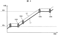
まず、本発明での列車の表示方法の特徴について説明する。図4は従来の列車表示方法について説明したものである。図5は本発明の列車表示方法について説明したものである。まず図4について説明し、その後比較する形で、図5について本発明の特徴的な表示方法を説明する。 First, the features of the train display method of the present invention will be described. FIG. 4 illustrates a conventional train display method. FIG. 5 explains the train display method of the present invention. 4 will be described first, and then the characteristic display method of the present invention will be described with reference to FIG.
図4は、物理的な列車形状に基づき列車の位置及び形状を標示する従来方法について示した図である。時刻を横軸に、位置を縦軸に表わしており、1003から1006はある時刻における列車位置及び形状を示す。図の例では駅αと駅β間の線路上に位置する停止あるいは走行中の列車が同一シンボルで表記されている。列車は同一形状、同一サイズの五角形のシンボルで表示され、五角形状の底辺部分(平らな側)をつなぐ実線L1は列車の末尾位置の移動軌跡、列車形状の先端部分(尖った側)をつなぐ点線L2は、列車の先頭位置の軌跡を表す。 FIG. 4 is a diagram showing a conventional method for marking the position and shape of a train based on the physical train shape. The time is represented on the horizontal axis and the position is represented on the vertical axis, and 1003 to 1006 indicate train positions and shapes at a certain time. In the example of the figure, a stopped or running train located on the track between the stations α and β is represented by the same symbol. The trains are displayed with pentagonal symbols of the same shape and size, and the solid line L1 that connects the bases (flat sides) of the pentagons connects the trajectory of the train end position and the tip of the train (pointed side). The dotted line L2 represents the trajectory of the top position of the train.
この図によれば、底辺部分が駅α、駅βに平行な位置に表示された記号1003、1005,1006で表示された列車などは、これらの駅に停車中であることを表す。また、駅αと駅β間に表記された記号1004の列車などは、この駅間の線路上に位置し、停止あるいは走行中の列車であることが分かる。なお、図4では、駅の位置を列車停止時の末尾位置で代表とし、時刻表の出発時間及び到着時間から算出した列車位置の軌跡とする。
According to this figure, the trains indicated by the
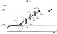
図5は、本発明の列車表示方法に基づき表示した列車の位置及び形状について示した図である。図4と同様に時刻を横軸に、位置を縦軸に表わしており、1014から1019のシンボルはある時刻における列車位置及び形状を示す。L1とL2は、図4と同様に列車の末尾位置の軌跡と、列車の先頭位置の軌跡である。
FIG. 5 is a diagram showing the position and shape of the train displayed based on the train display method of the present invention. As in FIG. 4, the time is represented on the horizontal axis and the position is represented on the vertical axis.
ここまでの表記は、図4のそれと同じであるが、本発明ではさらに以下の表記上の工夫がされている。第1点は、移動中の列車は図4と同様に列車先頭を尖らせて五角形のシンボルで表記するが、停車中では四角形のシンボルで表記する。1014,1019が停車中の列車を表す。これにより、駅間で停車している列車は四角形で表記されることになり、駅間走行中の列車と区別される。
The notation so far is the same as that shown in FIG. 4, but the present invention has the following notation. The first point is that the moving train is represented by a pentagonal symbol with the top of the train sharpened as in FIG. 4, but is represented by a square symbol when the vehicle is stopped.
第2点は、走行状態が五角形形状の長さに反映された点である。出発、到着時は、五角形形状の長さが加速、減速に伸縮し、駅間走行中は一定の長さで表される。第3点は、L1とL2以外に、L3としてダイヤの出発時間及び到着時間から算出した代表位置の軌跡を表示したことである。そのほかの特徴的な表示内容についてはその都度説明する。 The second point is a point where the running state is reflected in the length of the pentagonal shape. At the time of departure and arrival, the length of the pentagonal shape expands and contracts to accelerate and decelerate, and is expressed as a certain length during traveling between stations. The third point is that in addition to L1 and L2, the locus of the representative position calculated from the departure time and arrival time of the diamond is displayed as L3. Other characteristic display contents will be described each time.
なお、第1点と第2点の工夫は、要するに列車走行状態の変化を表示形状により表現したものということができる。ここでの表現事例では、列車走行状態が停止、駅間走行中、駅接近中、駅離脱中などが区別して表示される。これは、列車の先頭位置と末尾位置には常にΔtの時間差を持たせ、末尾位置から先頭位置までの時間幅Δtの移動軌跡により列車の表示形状を決定したことにより、列車走行状態の変化を表示形状により表現している。 In addition, it can be said that the device of the 1st point and the 2nd point expressed the change of a train running state with the display shape in short. In the expression example here, the train traveling state is stopped, traveling between stations, approaching a station, leaving the station, and the like are displayed separately. This is because there is always a time difference of Δt between the start position and the end position of the train, and the train display shape is determined by the movement trajectory of the time width Δt from the end position to the start position. It is expressed by the display shape.
図3は、図5に示した本発明の列車表示方法を用いて複数線区の列車運行状況を同時に示した図である。図3の列車位置表示画面は、例えば列車の運行管理室内のモニタなどに表示される。この図で、黒丸で示すSTは駅を示しており、Mは駅間の路線を示している。Tr1、Tr2、Tr3、Tr4は、列車の走行状態に応じて表示変更された列車のシンボルを表している。列車の走行状態は、ユーザあるいは装置が持つ表示時刻907及び、ダイヤによって決定される。
FIG. 3 is a diagram showing simultaneously the train operation status in a plurality of sections using the train display method of the present invention shown in FIG. The train position display screen in FIG. 3 is displayed on, for example, a monitor in a train operation management room. In this figure, STs indicated by black circles indicate stations, and M indicates a route between stations. Tr1, Tr2, Tr3, and Tr4 represent train symbols whose display has been changed according to the running state of the train. The running state of the train is determined by a
この表記によれば、停車中の列車Tr2(四角形表示)と走行中の列車(五角形表示)が識別可能であり、かつ列車シンボルの長さから速度などの列車走行状態の変化が表れており、その位置から駅間のおおよその位置が把握できる。かつこの表記では、当該時刻での列車運行の全体状況が容易に把握できる。 According to this notation, the stopped train Tr2 (rectangular display) and the running train (pentagonal display) can be identified, and the change of the train running state such as the speed from the length of the train symbol appears. The approximate position between stations can be grasped from that position. In this notation, the overall status of train operation at the time can be easily grasped.
本発明の列車表示方法では、列車の走行状態により表示形状を変化させている。これによって多数の列車が同時に表示された場合でも列車の表示形状から走行状態を確認することができる。線区全域の列車を同時に表示した場合でも、列車それぞれの走行状態により表示形状を変化させるため、同時に複数の列車の走行状態を確認することができる。 In the train display method of the present invention, the display shape is changed according to the running state of the train. Thereby, even when a large number of trains are displayed at the same time, the traveling state can be confirmed from the display shape of the trains. Even when the trains in the entire area are displayed simultaneously, the display shape is changed depending on the traveling state of each train, so the traveling states of a plurality of trains can be confirmed simultaneously.
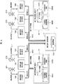
図1は本発明の列車表示方法を備えた列車の運行把握装置の構成を示している。図1を用いて列車の運行把握装置の構成について説明する。 FIG. 1 shows the configuration of a train operation grasping device provided with the train display method of the present invention. The configuration of the train operation grasping device will be described with reference to FIG.
列車の運行把握装置1は、列車位置表示部10、列車位置形状算出部11、列車走行駅間算出部12、列車情報取得部13で構成された演算部を備える。またこれらの演算に使用する入力情報や加工情報を蓄積するデータベースとして、路線情報データベースDB1、ダイヤ情報データベースDB2、列車遅延時間情報データベースDB3、列車乗車率情報データベースDB4の記憶部を有している。演算部及び記憶部はそれぞれ相互に接続されている。
The train
このうち列車位置表示部10は、路線情報データベースDB1から線区ごとの駅の並び及び駅の位置を取得し、路線図を表示する。例えば図3の路線構成をモニタ画面上に表記することを想定すると、路線情報データベースDB1は図7のような路線情報データを備えることになる。
Among these, the train
図7は、路線情報データベースDB1に記録されているデータについて示した図である。TB1は線区1、TB2は線区2の路線情報テーブルである。これらのテーブルTBには、当該線区内の駅名STと駅の位置512が記憶されている。この事例では、線区1は駅がA,B,C,D,E、Fの順に配置されて構成され、線区2はG,H,C,I,J,Kの順に配置され構成されている。また各駅の位置が例えば座標で記憶されている。
FIG. 7 is a diagram showing data recorded in the route information database DB1. TB1 is a route information table for
このようにTB1,TB2は、線区毎にその順序に従って路線を構成する駅の位置を記憶しており、少なくとも駅名と駅の位置を含む。駅の位置は、緯度・経度、または画面に駅を表示する簡易的な座標としてもよい。駅名とは、駅を一意に特定できる名称あるいはコードとする。 As described above, TB1 and TB2 store the positions of the stations constituting the route according to the order of each line section, and include at least the station name and the station position. The position of the station may be latitude / longitude or simple coordinates for displaying the station on the screen. The station name is a name or code that can uniquely identify the station.
路線情報データベースDB1から隣接する駅の位置が把握できるので、列車位置表示部10は、図3のモニタ画面のうち、駅の位置と駅間の線路を表示することができる。
Since the position of the adjacent station can be grasped from the route information database DB1, the train
図8は、ダイヤ情報データベースDB2に記憶されているダイヤ情報のデータの例を示している。図8において、TB3,TB4は列車ごとのダイヤ情報テーブルである。ここでダイヤ情報とは、列車が停車する駅ごとに出発時刻及び到着時刻を記憶した情報である。 FIG. 8 shows an example of diamond information data stored in the diamond information database DB2. In FIG. 8, TB3 and TB4 are schedule information tables for each train. Here, the diagram information is information that stores the departure time and arrival time for each station where the train stops.
TB3は例えば列車名316が「A701」である列車が、各駅に到着する時刻と出発する時刻をテーブル形式で記憶している。同様にTB4は列車名316が「A702」である列車が、各駅に到着する時刻と出発する時刻をテーブル形式で記憶している。図8の事例では、欄320にレコード番号、欄311に該当線区の通過駅の順に表記された駅名、312に到着/出発の区別、313に到着/出発の各時刻が記憶されている。
TB3 stores, for example, the time when a train whose
列車「A701」の事例だと、この列車は時刻07:10:00にA駅に到着して時刻07:10:32に出発し、次のB駅には時刻07:15:25にA駅に到着する予定である。なお、列車が通過するC駅については欄319のように出発時刻及び到着時刻は省略してもよい。
In the case of the train “A701”, this train arrives at the A station at the time 07:10:00 and departs at the time 07:10:32, and the next B station has the A station at the time 07:15:25. Is scheduled to arrive at. For station C through which the train passes, the departure time and arrival time may be omitted as in
ダイヤ情報テーブルTB3,TB4に記憶するダイヤ情報には種々のものが利用できる。例えば既に運行した列車の運行実績を記録した実績ダイヤ、または任意の予測時刻において、予測時刻以後の列車の運行を予測し記録した予測ダイヤのいずれを用いてもよい。また現時刻以前を実績ダイヤ、現時刻以後を予測ダイヤとして合わせて用いてもよい。 Various kinds of diamond information can be used for the diamond information stored in the diamond information tables TB3 and TB4. For example, either a performance diagram that records the operation results of trains that have already been operated, or a prediction diagram that predicts and records train operations after the prediction time at any predicted time may be used. Also, the time before the current time may be used as the actual schedule, and the time after the current time may be used as the prediction diamond.
列車位置表示部10は、さらに表示時刻tの情報を持つ。図1装置では、指定された表示時刻に基づき、ダイヤ情報テーブルTB3,TB4を参酌することにより、当該時刻の各列車の在線位置を知ることができる。これにより、図3のモニタ画面の上に、既に表示情報が得られている線路情報(駅の位置と駅間の線路)に重ねて当該時刻の各列車位置を表示することができる。
The train
但し、ダイヤ情報テーブルTB3,TB4に記憶されているダイヤ情報は、計画あるいは過去実績によるものであり、現実には当該時刻での遅れを考慮する必要がある。この点について、列車遅延時間情報データベースDB3に記録されている列車遅延時間のデータを参照する。 However, the diamond information stored in the diamond information tables TB3 and TB4 is based on a plan or a past record, and in reality, it is necessary to consider a delay at the time. Regarding this point, reference is made to train delay time data recorded in the train delay time information database DB3.
図9は、列車遅延時間情報データベースDB3に記録されている列車遅延時間のデータについて示した図である。列車遅延時間情報データベースDB3は、線区ごと、列車ごとかつ列車が停車する駅毎に列車遅延時間を記録した列車遅延時間テーブルTB5を備えている。図9の列車遅延時間テーブルTB5は、線区1の遅れ情報を記録しており、従って他の線区についても適宜同様の列車遅延時間テーブル作成記憶されている。
FIG. 9 is a diagram showing train delay time data recorded in the train delay time information database DB3. Train delay time information database DB3 is provided with train delay time table TB5 which recorded train delay time for every line section, every train, and every station where a train stops. The train delay time table TB5 of FIG. 9 records the delay information of the
この図で横方向の欄406、407、408は列車名であり、それぞれ「A701」、「A702」、「A703」、「A704」を表わしている。縦方向の欄402は、線区1内の駅名が通過順に記載されている。図のマトリクスの横方向の列車名と縦方向の駅名の交点の欄に、当該列車の当駅における遅れ時間が記載されている。
In this figure,
この図9の列車遅延時間テーブルTB5によれば、例えば列車名406が「A701」の列車は、A駅を定刻に発車したが、B駅では5秒、次のC駅では10秒、さらに次のD駅では15秒というように、遅れを増して運行されたことが見て取れる。
According to the train delay time table TB5 in FIG. 9, for example, a train with the
なお、ダイヤ情報データベースDB2が実績ダイヤであるとき、各列車遅延時間の値は、予め運行を計画していた出発時刻に対して列車の運行実績の出発時刻の遅れ時間を記録する。ダイヤ情報データベースDB2が予測ダイヤであるとき、各列車遅延時間の値は、予め運行を計画していた出発時刻に対して予測される列車運行の出発時刻の遅延時間を記録する。409に示すように通過駅についてはその列車遅延時間を省略してもよい。 When the diagram information database DB2 is a record diagram, the value of each train delay time records a delay time of the departure time of the train operation record with respect to the departure time planned for the operation in advance. When the diagram information database DB2 is a prediction diagram, the value of each train delay time records the delay time of the departure time of the train operation predicted with respect to the departure time planned for the operation in advance. As shown at 409, the train delay time may be omitted for the passing station.
列車位置表示部10において、図3の画面をモニタに表示するにあたり、当該時刻の列車位置の表示には、ダイヤ情報テーブルTB3,TB4に記憶されているダイヤ情報に、列車遅延時間テーブルTB5の各列車の遅れ情報が加味されることで、より正確な現在位置表示が行える。
When the train
列車位置表示部10において、図3の画面をモニタ表示するにあたり、さらに図10の列車乗車率情報データベースDB4に記録されているデータを考慮するのが良い。列車乗車率情報データベースDB4には、線区ごと、列車ごと、かつ列車が走行する駅間ごとに列車乗車率を記録した列車乗車率情報が、列車乗車率テーブルTB6として保持されている。
When the train
図10の列車乗車率テーブルTB6において、縦方向には駅間、横方向606、607、608の列には列車名を記載している。駅間602の欄は、左が出発駅、右が到着駅として列車が走行する駅間を表している。縦横のマトリクスの交点には、列車番号に対応した列車乗車率を表す。なお609に示すように通過駅の列車乗車率は省略してよい。
In the train occupancy rate table TB6 in FIG. 10, train names are described in the columns of the stations in the vertical direction and in the columns of the
図10の事例によれば、列車A701は、AB駅間の乗車率が最も高く、A駅から離れるほど乗車率が低下する傾向が見て取れる。 According to the example of FIG. 10, the train A701 has the highest boarding ratio between AB stations, and it can be seen that the boarding ratio tends to decrease as the distance from the A station increases.
図1の運行把握装置1では、以上の各種データベースに記憶された情報を利用して、指定された表示時刻に基づき、列車位置形状算出部11から列車の先頭位置及び末尾位置を取得し、列車情報取得部13から列車遅延時間及び列車乗車率を取得する。また先頭位置、末尾位置、列車遅延時間、及び列車乗車率を入力として、列車の表示位置及び形状、表示色を算出し、画面に図3に示した列車運行状況を表示する。
In the
係る画面表示のために、図1の運行把握装置の各部は、概略以下のように作動する。例えば列車位置表示部10は、ユーザからの入力を受け付けて表示時刻を任意に変更可能とする。また前回表示した表示時刻tから、任意の時間間隔で表示時刻tを自動で繰り返し進め、表示時刻tを進めると同時に画面の列車運行状況についても更新可能とする。
In order to display the screen, each part of the operation grasping device in FIG. 1 operates as follows. For example, the train
列車位置形状算出部11は、列車走行駅間算出部12から取得した列車が走行する駅間または停車駅と、表示時刻と路線情報データベースDB1を入力として、列車先頭位置及び末尾位置を算出する。
The train position shape calculation unit 11 calculates the train start position and the end position by inputting the inter-station or stop station on which the train acquired from the train traveling
列車走行駅間算出部12は、列車位置表示部10から表示時刻とダイヤ情報データベースDB2を入力として受け取り、列車が走行する駅間あるいは停車駅を出力として、列車位置表示部10に返す。
The train traveling
列車情報取得部13は、列車位置表示部11から列車を一意に識別できる列車番号と前記列車が走行する駅間または停車駅を入力として受け取り、列車遅延時間情報データベースDB3から列車遅延時間を取得し、列車乗車率情報データベースDB4から列車乗車率を出力として、列車位置表示部10に返す。
The train
次に、本実施例における運行把握装置1各部の処理の流れについて、図11、図12、図13を用いて説明する。まず図11は、列車位置表示部10の列車位置表示処理のフローチャートについて示した図である。
Next, the flow of processing of each part of the
ステップS101はループ処理であり、このループ1では、対象とする線区をSとして全線区に対して以下のステップS102〜ステップS112の対象となるステップを繰り返す。
Step S101 is a loop process. In this
なお、このループ1の処理は、ステップS101とステップS113が対(開始点と終了点)になっており、この間の処理を繰り返し実行することを意味している。同様のループ処理は、同図においてループ2としても定義されており、ステップS103とステップS112が対になって、この間の処理を繰り返し実行している。
Note that the processing of the
ステップS102では、線区Sの線区情報を読み込む。ここでは最初に線区1を読み込む。線区1についてのループ2の全てのステップでの処理が終了すると、次に線区2を選択して同様の一巡処理を完遂するまで、実行する。線区1の線区情報は、図7の線路情報テーブルTB1に保持されており、A駅からB,C,D,E,F駅の順に配置された複数駅の位置情報が取得される。
In step S102, the line area information of line area S is read. Here,
次にステップS103のループ2では、対象とする列車をnとして、線区S(ここでは最初に選択した線区1を対象とする)の全列車に対して以下のステップS104からステップS111の対象となるステップを繰り返す。
Next, in
ステップS104では、ダイヤ情報データベースDB1から列車nのダイヤ情報を読み込む。具体的には、ダイヤ情報データベースDB1について、最初にダイヤ情報テーブルTB3を参照して列車A701のダイヤ情報を読み込む。線区1を走行する列車は他にもあり、図8のテーブルは列車ごとに構築されているので、順次テーブルを参照して全ての列車のダイヤ情報を読み込む。
In step S104, the schedule information of train n is read from the schedule information database DB1. Specifically, with respect to the diagram information database DB1, first, the diagram information of the train A701 is read with reference to the diagram information table TB3. There are other trains traveling in the
ステップS105では、入力を表示時刻t、列車nとして、列車走行駅間算出処理を行う。この処理結果の出力として、時刻tに列車nが走行する駅間または停車駅を表わす駅αと駅βと、時刻Tα、時刻Tβを、列車走行駅間算出部12により算出する。
In step S105, the input between the display time t and the train n is performed, and a calculation process between train traveling stations is performed. As an output of this processing result, the inter-train traveling
たたしここで、駅αは列車nの時刻tより前で直近の出発駅または到着駅、Tαは列車nの時刻tより前で直近の出発の時刻または到着の時刻とする。駅βは列車nの時刻tより後で直近の出発駅または到着駅、Tβは列車nの時刻tより後で直近の出発の時刻または到着の時刻とする。 Here, the station α is the latest departure or arrival station before the time t of the train n, and T α is the latest departure time or arrival time before the time t of the train n. Station β is the latest departure or arrival station after time n of train n, and T β is the latest departure time or arrival time after time t of train n.
例えば図8の列車A701について、時刻tを07:12:00とする例で説明すると、駅αは時刻tより前で直近の出発駅Aであり、Tαは時刻tより前で直近の出発時刻7:10:32である。駅βは時刻tより後で直近の到着駅Bであり、Tβは時刻tより後で直近の到着時刻7:15:25である。この結果では、駅α≠駅βとなり、列車A701が走行中であることを示し、駅α(駅B)から駅β(駅A)の駅間で列車A701が走行していることが判明する。 For example, in the case of train A701 in FIG. 8, when time t is set to 07:12:00, station α is the latest departure station A before time t, and T α is the latest departure before time t. Time is 7:10:32. Station β is the latest arrival station B after time t, and T β is the latest arrival time 7:15:25 after time t. This result shows that the station α ≠ station β, indicating that the train A701 is traveling, and that the train A701 is traveling between the station α (station B) and the station β (station A). .
同様に例えば図8の列車A701について、時刻tを07:10:20とする例で説明すると、駅αは時刻tより前で直近の到着駅Aであり、Tαは時刻tより前で直近の到着時刻7:10:00である。駅βは時刻tより後で直近の出発駅Aであり、Tβは時刻tより後で直近の出発時刻7:10:32である。この結果では、駅α(駅A)=駅β(駅A)となり、列車A701が駅Aに停車していることを示し、駅α及び駅βは停車駅を表していることが判明する。 Similarly, for example, in the case of the train A701 in FIG. 8, when the time t is set to 07:10:20, the station α is the latest arrival station A before the time t, and T α is the latest before the time t. Arrival time of 7:10:00. Station β is the latest departure station A after time t, and T β is the latest departure time 7:10:32 after time t. This result shows that station α (station A) = station β (station A), indicating that the train A701 has stopped at the station A, and that the stations α and β represent the stop stations.
なお、時刻tが07:10:00よりも前の時刻が指定されたとき、駅α=不定または駅β=不定となり、この場合表示時刻tが列車の始発時刻以前または終着時刻以後であり列車nが運行していないことを示す。 When the time t is specified before 07:10:00, the station α = undefined or the station β = undefined, and in this case, the display time t is before the first departure time or after the last arrival time of the train. Indicates that n is not operating.
ステップS106では、列車が運行中のとき、つまり駅α≠不定かつ駅β≠不定のとき、ステップS107へと進む。一方、列車が運行中でないとき、駅α=不定または駅β=不定のとき、ステップS112へ進み列車nを対象とする処理を終了する。 In step S106, when the train is in operation, that is, when the station α is not constant and the station β is not constant, the process proceeds to step S107. On the other hand, when the train is not in operation, when the station α = indefinite or the station β = indefinite, the process proceeds to step S112 and the process for the train n is terminated.
ステップS107では、時刻tにおける列車nの先頭位置をp1、末尾位置をp2とし、先頭位置p1、末尾位置p2をそれぞれ列車位置形状算出部11から算出する。時間幅Δtの移動の変化(つまり列車速度)を列車形状に反映するため、先頭位置p1と末尾位置p2にはΔtの時間差を持つこととする。列車位置形状算出部11での処理については後述する。 In step S107, the start position of train n at time t is set as p 1 , the end position is set as p 2 , and the start position p 1 and the end position p 2 are respectively calculated from the train position shape calculation unit 11. In order to reflect the change in movement of the time width Δt (that is, the train speed) in the train shape, the head position p 1 and the tail position p 2 have a time difference of Δt. The processing in the train position shape calculation unit 11 will be described later.
ステップS108では、駅間または停車駅を表す駅α、駅βにおける列車nの列車遅延時間uと列車乗車率vを列車情報取得部13から取得する。列車遅延時間uは、列車遅延時間情報データベースDB3から取得し、列車乗車率vは列車乗車率情報データベースDB4から取得する。
In step S <b> 108, the train
列車遅延時間情報データベースDB3は駅毎に記録されているため、駅αに対応した列車遅延時間uを取得することとする。列車乗車率情報データベースDB4は駅間毎に記録されているため、駅間α、βに対応する列車乗車率を取得する。ただし、α=βのときには、駅間602の出発駅(左)と駅βが一致する列車乗車率を取得する。
Since the train delay time information database DB3 is recorded for each station, the train delay time u corresponding to the station α is acquired. Since the train boarding rate information database DB4 is recorded for each station, the train boarding rate corresponding to α, β between the stations is acquired. However, when α = β, the train boarding rate at which the departure station (left) of the station-to-
ステップS109では、列車nの表示色cを列車遅延時間uまたは列車乗車率vから算出する。表示色cの算出方法は後述する。 In step S109, the display color c of the train n is calculated from the train delay time u or the train boarding rate v. A method for calculating the display color c will be described later.
ステップS110では、列車nの表示サイズwを列車遅延時間uまたは列車乗車率vから算出する。表示サイズwの算出方法は後述する。 In step S110, the display size w of the train n is calculated from the train delay time u or the train boarding rate v. A method for calculating the display size w will be described later.
ステップS111では、前記表示サイズw、表示色c、先頭位置p1、末尾位置p2を用いて、列車nを画面に表示する。 In step S111, by using the display size w, display color c, head position p 1, the tail position p 2, and displays the train n the screen.
ステップS112で列車nを対象とする処理は終了し、ステップS103に戻り線区Sの全列車について処理を終えるまで繰り返し実行する。 In step S112, the process for the train n ends, and the process returns to step S103 and is repeated until the process is completed for all the trains in the line section S.
ステップS113で線区Sを対象とする処理は終了し、ステップS101に戻り全線区について処理を終えるまで繰り返し実施する。 In step S113, the process for line segment S ends, and the process returns to step S101 and is repeated until the process is completed for all line segments.
列車表示処理についての説明は以上である。 This is the end of the description of the train display process.
次に、列車の表示色及び形状を決定する手法について詳細に説明する。図6は列車の形状及び、列車の表示色を決める色モデルについて示した図である。 Next, a method for determining the display color and shape of the train will be described in detail. FIG. 6 is a diagram showing a color model that determines the shape of the train and the display color of the train.
図6において、1020は列車の先頭位置p1と列車の末尾位置p2の位置が同じでない場合の列車の表示形状を表し、1021は先頭位置p1、1022は末尾位置p2を表す。1020が走行中の列車シンボルとなる。
6, 1020 represents a train display shape when the position of the head position p 1 and the train tail position p 2 of the train is not the same, 1021
1026は列車の先頭位置p1及び末尾位置p2が同じ位置の時の列車の表示形状を表し、1025は先頭位置p1及び末尾位置p2を表す。1026が停車中の列車シンボルとなる。 1026 represents the display shape of the train when the start position p 1 and the end position p 2 of the train are the same position, and 1025 represents the start position p 1 and the end position p 2 . 1026 becomes a stopped train symbol.
1024は列車の表示サイズwを表す。表示サイズwは列車毎に算出し、列車乗車率vまたは、列車遅延時間uに比例させて大きくする。 1024 represents the display size w of the train. The display size w is calculated for each train and is increased in proportion to the train occupancy rate v or the train delay time u.
1023及び1027は表示色cで塗りつぶす領域を表す。表示色cは、列車遅延時間の色モデル1031または列車乗車率の色モデル1034から決定する。色モデル1031及び1034は一般に知られるHSB色空間モデルを基に、彩度及び明度を100%とし、色相を列車遅延時間または列車乗車率に応じて66%から0%へと色相を変化させることで表示色cを決定する。
列車遅延時間uによって表示色cを決定する場合には、1032に示すように遅れ時間が0分のときは色相66%の青とし、列車遅延時間uが大きくなるに従い色相の値も大きくし、1033に示すように列車遅延時間uが60分以上のときには色相0%の赤とする。 When the display color c is determined by the train delay time u, as shown by 1032, when the delay time is 0 minutes, the hue is 66% blue, and the hue value is increased as the train delay time u is increased. As shown in 1033, when the train delay time u is 60 minutes or more, the hue is 0% red.
列車乗車率vによって表示色cを決定する場合には、1035に示すように列車乗車率が0%のときは色相66%の青とし、列車乗車率vが大きくなるに従い色相の値も大きくなり、1036に示すように列車乗車率vが300%以上のときには色相0%の赤とする。 When the display color c is determined based on the train occupancy rate v, as shown by 1035, when the train occupancy rate is 0%, the hue is 66% blue, and the hue value increases as the train occupancy rate v increases. 1036, when the train occupancy rate v is 300% or more, the hue is 0% red.
図6の表示において、例えば列車の表示サイズwを列車乗車率vで定めた場合には、標示色cを列車遅延時間uで定めることになる。逆に、列車の表示サイズwを列車遅延時間uで定めた場合には、標示色cを列車乗車率vで定めることになる。モニタ画面表示上は、いずれかに統一しておけばよい。 In the display of FIG. 6, for example, when the display size w of the train is determined by the train boarding rate v, the marking color c is determined by the train delay time u. Conversely, when the train display size w is determined by the train delay time u, the marking color c is determined by the train boarding rate v. The display on the monitor screen should be unified.
列車表示形状の詳細についての説明は以上である。 This completes the description of the details of the train display shape.
本発明の列車表示方法では、列車の走行状態により表示形状及び表示色を変化させている。これによって多数の列車が同時に表示された場合でも列車の表示形状から走行状態を確認することができる。線区全域の列車を同時に表示した場合でも、列車それぞれの走行状態により表示形状を変化させるため、同時に複数の列車の走行状態を確認することができる。 In the train display method of the present invention, the display shape and display color are changed according to the running state of the train. Thereby, even when a large number of trains are displayed at the same time, the traveling state can be confirmed from the display shape of the trains. Even when the trains in the entire area are displayed simultaneously, the display shape is changed depending on the traveling state of each train, so the traveling states of a plurality of trains can be confirmed simultaneously.
図12は列車走行駅間算出部12の列車走行算出処理のフローチャートについて示した図である。
FIG. 12 is a diagram illustrating a flowchart of the train travel calculation process of the train travel station-to-
まずステップS201では、初期化処理として、ダイヤ情報のレコードNo.とした変数i=1とし、本列車走行駅間算出処理終了時に出力する前記の駅α、駅β、時刻Tα、時刻Tβをすべて不定として初期化する。 First, in step S201, as an initialization process, a record information record No. And the above-mentioned station α, station β, time T α, and time T β that are output at the end of the calculation process between train traveling stations are initialized as undefined.
ステップSTMでは、iがダイヤ情報(ダイヤ情報データベースDB2,図8のダイヤ情報テーブルTB3,TB4)のレコード数より小さいこと、つまりiがダイヤ情報のレコードNoに含まれることを繰り返し条件とし、繰り返し条件を満たす間、つまり全レコードを対象としてステップSTMからステップS206までのステップを繰り返す。 In step STM, the repetition condition is that i is smaller than the number of records in the diagram information (diagram information database DB2, diagram information table TB3, TB4 in FIG. 8), that is, i is included in the record number of the diagram information. Steps STM to S206 are repeated while satisfying the condition, that is, for all records.
ステップS203では、ダイヤ情報のレコードNo.がi−1の時刻をTi−1とし、ダイヤ情報のレコードNo.がiの時刻をTiとする。例えばレコードNo.iを図8の列車A701のダイヤ情報テーブルTB3の「3」、i−1を同テーブルの「2」としたとき、i−1の時刻Ti−1が07:10:32であり、iの時刻Tiが07:15:25とされる。 In step S203, a record information record No. Is set to T i-1, and the record information record No. Let i be the time of i . For example, record No. When i is “3” in the diagram information table TB3 of the train A701 in FIG. 8 and i-1 is “2” in the table, the time T i-1 of i-1 is 07:10:32, and i time T i of is the 07:15:25.
ステップS204では、列車n(A701)のダイヤ情報においてTi−1、Tiが任意の表示時刻tの前後直近の出発または到着の時刻となるとき、つまり、Ti−1<t<Tiのとき、ループ1を抜けステップS207に進み、それ以外のときステップS206へ進む。
In step S204, when T i-1 and T i are the latest departure or arrival time before and after the arbitrary display time t in the schedule information of train n (A701), that is, T i-1 <t <T i. At this time, the process exits
ステップS207では、ステップS204を満たすとき、レコードNo.i−1の駅は、駅αの条件(時刻t以前の直近の出発または到着駅)を満たすため、ダイヤ情報のNo.がi−1の駅名をαとし、その時刻Ti−1をTαとする。また、レコードNo.i−1の駅も、駅βの条件(時刻tより後の直近の出発または到着駅)を満たすため、ダイヤ情報のNo.がiの駅名をβとし、その時刻T iをTβとする。前記駅α、駅β、時刻Tα、時刻Tβを出力して終了する。 In step S207, when step S204 is satisfied, the record No. Since the station of i-1 satisfies the condition of the station α (the latest departure or arrival station before the time t), the station information No. But the i-1 of the station name and α, to the time T i-1 and T α. In addition, record No. Since the station of i-1 also satisfies the condition of the station β (the latest departure or arrival station after the time t), the station information No. Is the station name of i, and its time T i is T β . The station α, station β, time T α , and time T β are output and the process ends.
この判断によれば、例えばステップS204の具体事例の場合には、駅αとして駅A、駅βとして駅B、時刻Tαとして07:10:32、時刻Tβとして07:15:25が決定される。 According to this determination, the case of the specific case, for example, step S204 is the station A as the station-alpha, station B as the station-beta, as the time T α 07:10:32, as the time T β 07:15:25 decision Is done.
ステップS205では、i=i+1として、レコードiの値に1を加える。 In step S205, i = i + 1 and 1 is added to the value of record i.
ステップS206では、ステップSTMの繰り返し条件を満たす場合はステップSTMに戻り、ステップSTMの繰り返し条件を満たさない場合にはループ1を抜ける。駅α、駅βに該当するデータが存在しなかったため、駅α、駅β、時刻Tα、時刻Tβはすべて不定のままである処理を終了する。
In step S206, when the repetition condition of step STM is satisfied, the process returns to step STM, and when the repetition condition of step STM is not satisfied,
以上で、列車走行算出処理の説明を終了する。 Above, description of a train travel calculation process is complete | finished.
図13は列車位置形状算出部11の列車位置形状算出処理のフローチャートについて示した図である。列車位置形状算出部11では、時間幅Δtの列車の移動軌跡となるように、列車の先頭位置p1及び末尾位置p2を算出する処理を行う。 FIG. 13 is a diagram illustrating a flowchart of the train position shape calculation process of the train position shape calculation unit 11. The train position shape calculation unit 11 performs a process of calculating the start position p 1 and the end position p 2 of the train so as to be a movement trajectory of the train having the time width Δt.
ステップS301では、先頭位置の時刻t1と末尾位置の時刻t2を、表示時刻tを基準として、t1=t、t2=t−Δt=t1−Δtと算出する。 In step S301, the time t 1 at the head position and the time t 2 at the tail position are calculated as t 1 = t and t 2 = t−Δt = t 1 −Δt with reference to the display time t.
ステップS302では、駅α、βについて、それぞれの位置を路線情報から取得し、駅αの位置をPα、駅βの位置をPβとする。 In step S302, the positions of the stations α and β are acquired from the route information, the position of the station α is P α , and the position of the station β is P β .
ステップS303では、列車走行中の時、つまりα≠βのときステップS304へと進み、列車停止中のとき、つまりα=βのときにはステップS305へと進む。 In step S303, when the train is running, that is, when α ≠ β, the process proceeds to step S304, and when the train is stopped, that is, when α = β, the process proceeds to step S305.
ステップS304では、走行中の列車の先頭位置及び末尾位置をそれぞれ後述する(1)式から求める。ここでは、表示位置tを基準とする異なる2つの時刻t1、t2から先頭位置及び末尾位置を算出する。 In step S304, the starting position and the ending position of the running train are obtained from equation (1) described later. Here, the head position and the tail position are calculated from two different times t 1 and t 2 with reference to the display position t.

表示時刻tの先頭位置を時刻t1の位置p(n,t1)、表示時刻tの末尾位置を時刻t2の位置p(n,t2)として算出する。時間幅Δtの列車の移動軌跡となるように、(1)式は表示時刻tと先頭位置の関係を示した式とし、時刻t2は時刻t1からΔt遅らせた位置となるようにt2=t1−Δtとしている。(1)式の詳細については後述する。その後、処理を終了する。 Position at time t 1 the head position of the display time t p (n, t 1) , and calculates the end position of the display time t the position p (n, t 2) at time t 2 as. As the movement locus of the train duration Delta] t, (1) formula is display time t and the expression showing the relation between the head position, the time t 2 as is the position which is delayed Delta] t from the time t 1 t 2 = T 1 −Δt. Details of the expression (1) will be described later. Thereafter, the process ends.
ステップS305では、駅に停車中の列車の先頭位置及び末尾位置を、駅αの位置Pαとする。その後、処理を終了する。 In step S305, the start position and end position of the train parked at the station, as the position P α of the station α. Thereafter, the process ends.
なお、ステップS304の処理で得られる走行中列車のシンボルが図6の1020の五角形形状のものであり、走行中列車の先頭位置p1、及び末尾位置p2が決定された。またステップS305の処理で得られる停止中列車のシンボルが図6の1024の四角形形状のものであり、走行中列車の先頭位置、末尾位置が駅αの位置Pαとして決定された。以上で、列車位置形状算出処理の説明を終了する。
Note that the symbol of the traveling train obtained in the process of step S304 has a
本実施例での列車位置表示部10の画面に表示する列車の表示形状の詳細について図14を用いて説明する。
Details of the display shape of the train displayed on the screen of the train
図14は、本発明の列車表示方法に基づき列車の位置及び形状の表示について示した図である。時刻を横軸に、位置を縦軸に表わしている。なお、L1は列車の末尾位置の軌跡、L2は列車の先頭位置の軌跡、L3は時刻表の出発時間及び到着時間から算出した位置の軌跡を表している。 FIG. 14 is a diagram showing the display of the position and shape of the train based on the train display method of the present invention. The time is represented on the horizontal axis and the position is represented on the vertical axis. Note that L1 represents the trajectory of the end position of the train, L2 represents the trajectory of the start position of the train, and L3 represents the trajectory of the position calculated from the departure time and arrival time of the timetable.
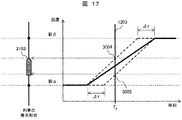
この図の表記によれば時刻T1のとき列車は駅αに停車中の状態であり、その表示形状の詳細を図15に示す。時刻T2のときの列車は駅αから出発直後の状態であり、その表示形状の詳細を図16に示す。時刻T3、T4のときの列車は駅αから駅βの駅間を走行中の状態であり、時刻T3の表示形状の詳細を図17に示す。時刻T5のときの列車は駅βに到着直前の状態であり、その表示形状の詳細を図18に示す。時刻T6のときの列車は駅βで停止中の状態であり、その表示形状の詳細を図19に示した。以下、順に説明する。 This train at time T 1 according to the representation of the figure is a state that is stopped on the station alpha, showing details of the display shape in FIG. Train when the time T 2, is in a state immediately after starting the station alpha, showing details of the display shape in FIG. The train at time T 3 and T 4 is in a state of traveling between the stations α to β, and FIG. 17 shows the details of the display shape at time T 3 . Train at time T 5 is a state of just before arriving at the station β, showing the details of the display shape in Figure 18. Train at time T 6 is the state of the stopped at the station beta, showing details of the display shape in FIG. Hereinafter, it demonstrates in order.
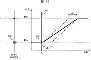
図15は、停車中の列車の表示形状として出発直前の時刻T1の表示形状について示した図である。停車中とは、ダイヤ上の到着時刻から出発時刻までの間の状態を指す。停車中の先頭位置及び末尾位置は駅α3001にあるので、表示形状は四角形の3101とする。図6で示したシンボル1026のように、駅の位置を中心とした幅・高さを表示サイズとした矩形となる。この形状によって停車中の状態を表現することができる。
Figure 15 is a diagram showing the display shape of the time T 1 of the immediately preceding starting as train display shape parked. Stopping refers to the state between the arrival time on the diamond and the departure time. Since the stop position and the start position are at the station α3001, the display shape is a square 3101. Like the
図16は、出発直後の列車の表示形状として時刻T2の表示形状について示した図である。出発直後とは、ダイヤ上の出発時刻からΔt秒後までの間の状態を指す。出発直後の先頭位置は3002となり駅αからは移動を開始しているが、末尾位置は3003となり駅αから移動を開始していない。そのため、出発直後の列車の表示は3102に示すように、時間経過とともに列車長が伸びる。この変化によって出発直後の状態を表現することができる。 Figure 16 is a diagram showing the display shape of the time T 2, as the display shape of the train immediately after starting. The term “immediately after departure” refers to a state between the departure time on the diagram and after Δt seconds. The start position immediately after departure is 3002, and movement starts from the station α, but the end position is 3003, and movement has not started from the station α. Therefore, as shown in 3102, the train length immediately after departure increases the train length with time. The state immediately after departure can be expressed by this change.
図17は、走行中の列車の表示形状として時刻T3の表示形状について示した図である。走行中とは、列車が出発時刻からΔt秒以上経過し、次の到着時刻までΔt秒以上である間の状態を指し、走行中の列車の表示は3103に示すように、列車長は伸びきって固定となる。この状態の列車先頭位置が3004、末尾位置は3005となり、この変化によって走行中の状態を表現することができる。 Figure 17 is a diagram showing the display shape of the time T 3 as train display shape during running. “Running” means a state in which the train has passed Δt seconds or more from the departure time and is longer than Δt seconds until the next arrival time. Fixed. In this state, the train head position is 3004 and the end position is 3005, and this change can express the running state.
図18は、到着直前の列車の表示形状として時刻T5の表示形状について示した図である。到着直前とは、列車が次の到着時刻までΔt秒以内である間の列車走行状態を指し、到着直前の列車の表示は3104に示すように、列車形状は到着時刻に近付くに従い列車長が徐々に短くなっていく。この状態の列車先頭位置が3006、末尾位置は3007となり、この変化によって到着直後の状態を表現することができる。この変化によって到着直前の状態を表現することができる。 Figure 18 is a diagram showing the display shape of the time T 5 as just before the arrival of the train of the display shape. The term “immediately before arrival” refers to the train running state while the train is within Δt seconds until the next arrival time. As shown in 3104, the train just before arrival arrives at the train length gradually toward the arrival time. It will become shorter. In this state, the train start position is 3006 and the end position is 3007. By this change, the state immediately after arrival can be expressed. The state immediately before arrival can be expressed by this change.
図19は、停止中の表示形状として到着直後の時刻T6の表示形状について示した図である。到着直後から、図15で示した出発直前の停止中の表示形状と同様になる。 Figure 19 is a diagram showing the display shape of the time T 6 immediately after arrival as the display shape of the stopped. Immediately after arrival, the display shape is the same as that shown in FIG.
以上で列車の表示形状の詳細についての説明を終了する。 This is the end of the description of the details of the train display shape.
本実施例の列車位置表示方法及び、列車運行把握装置により、停車中、出発直後、走行中、到着直前の4つの状態を列車位置及び形状から確認することができる。また同時に、列車の描画色C、幅Wによって列車の遅延時間や乗車率を可視化しているため、どのあたりの列車がどの程度遅延していたのか列車遅延時間をマクロにとらえることが可能となる。またどのあたりの列車がどの程度混雑していたのか列車乗車率をマクロにとらえることが可能となる。これにより効果的な列車の運行計画の立案あるいは運行計画の変更を実施することが可能となる。 With the train position display method and train operation grasping device of the present embodiment, four states immediately before stopping, immediately after departure, during traveling, and immediately before arrival can be confirmed from the train position and shape. At the same time, since the train delay time and boarding rate are visualized by the train drawing color C and width W, the train delay time can be captured in a macro as to which train was delayed. . In addition, it is possible to take the train occupancy rate as a macro based on how crowded the train is. This makes it possible to make an effective train operation plan or change the operation plan.
本発明の列車及び移動体の表示方法、運行把握装置の他の一実施例について説明する。 Another embodiment of the train and moving body display method and operation grasping apparatus of the present invention will be described.
本実施例の構成及び、使用するデータについては実施例1と同様であるため、その説明を省略する。 Since the configuration of this embodiment and the data to be used are the same as those of the first embodiment, description thereof is omitted.
本実施例における処理の流れについて、図20を用いて説明する。図20は列車位置表示部10の列車表示処理のフローチャートについて示した図である。実施例2の図20は、実施例1の図11に対応する列車表示処理であり、多くの部分の処理は同じものである。相違する処理ステップには二重枠表示したように、ステップS114からステップS117での処理が相違する。
The processing flow in the present embodiment will be described with reference to FIG. FIG. 20 is a diagram illustrating a flowchart of the train display process of the train
まずステップS101のループ1では、対象とする線区をSとして全線区に対して以下のステップS102〜ステップS107、およびステップS114〜ステップS117の対象となるステップを繰り返す。
First, in the
ステップS102では、線区Sの線区情報を読み込む。 In step S102, the line area information of line area S is read.
ステップS103のループ2は、対象とする列車をnとして線区Sの全列車に対して以下のステップS104〜ステップS107、およびステップS114〜ステップS117の対象となるステップを繰り返す。
The
ステップS104では、ダイヤ情報データベースDB1から列車nのダイヤ情報を読み込む。 In step S104, the schedule information of train n is read from the schedule information database DB1.
ステップS105では、入力を表示時刻t、列車nとして、列車走行駅間算出処理を行い、出力として、時刻tに列車nが走行する駅間または停車駅を表わす駅αと駅βと、時刻Tα、時刻Tβを、列車走行駅間算出部により算出する。 In step S105, the input is the display time t, the train n, and the calculation process between the train traveling stations is performed, and the output is the station α and the station β representing the distance between the stations where the train n travels at the time t or the stop station, and the time T. α and time T β are calculated by the train traveling station calculation unit.
駅αは列車nの時刻tより前で直近の出発駅または到着駅、Tαは列車nの時刻tより前で直近の出発の時刻または到着の時刻とする。駅βは列車nの時刻tより後で直近の出発駅または到着駅、Tβは列車nの時刻tより後で直近の出発の時刻または到着の時刻とする。 The station α is the nearest departure or arrival station before the time t of the train n, and T α is the latest departure time or arrival time before the time t of the train n. Station β is the latest departure or arrival station after time n of train n, and T β is the latest departure time or arrival time after time t of train n.
駅α≠駅βのとき、列車が走行中であることを示し、駅αから駅βの駅間が列車の走行する駅間を表す。駅α=駅βのとき、列車が駅に停車していることを示し、駅α及び駅βは停車駅を表す。駅α=不定または駅β=不定のとき、表示時刻tが列車の始発時刻以前または終着時刻以後であり列車nが運行していないことを示す。列車走行駅間処理については後述する。 When the station α is not equal to the station β, it indicates that the train is running, and the station between the station α and the station β represents the distance between the stations on which the train runs. When the station α = the station β, it indicates that the train is stopped at the station, and the stations α and β represent the stop stations. When the station α = indefinite or the station β = indefinite, the display time t is before the start time of the train or after the end time, and the train n is not operating. The train traveling station processing will be described later.
ステップS106では、列車が運行中のとき、つまり駅α≠不定かつ駅β≠不定のとき、ステップS107へと進む。一方、列車が運行中でないとき、駅α=不定または駅β=不定のとき、ステップS112へ進み列車nを対象とする処理を終了する。 In step S106, when the train is in operation, that is, when the station α is not constant and the station β is not constant, the process proceeds to step S107. On the other hand, when the train is not in operation, when the station α = indefinite or the station β = indefinite, the process proceeds to step S112 and the process for the train n is terminated.
ステップS107では、時刻tにおける列車nの先頭位置をp1、末尾位置をp2とし、先頭位置p1、末尾位置p2をそれぞれ列車位置形状算出部から算出する。時間幅Δtの移動の変化を列車形状に反映するため、先頭位置p1と末尾位置p2にはΔtの時間差を持つこととする。列車位置形状算出部での処理については後述する。 In step S107, the start position of train n at time t is p 1 , the end position is p 2 , and the start position p 1 and end position p 2 are calculated from the train position shape calculation unit. In order to reflect the change in the movement of the time width Δt in the train shape, the head position p 1 and the tail position p 2 have a time difference of Δt. Processing in the train position shape calculation unit will be described later.
実施例2の図20の上記の処理は、実施例1の図11と同じであり、以下において処理内容が相違する。 The above-described processing of FIG. 20 of the second embodiment is the same as that of FIG. 11 of the first embodiment, and the processing contents are different in the following.
まずステップS114では、駅間または停車駅を表す駅α、駅βにおける列車nの列車遅延時間uと列車乗車率の変化v1,v2を列車情報取得部13から取得する。列車遅延時間uは、列車遅延時間情報データベースDB3から取得し、列車乗車率v1,v2は列車乗車率情報データベースDB4から取得する。
First, in step S114, the train
なお列車遅延時間情報データベースDB3は、図9に示すように駅毎に列車遅延時間が記録されているため、駅αに対応した列車遅延時間uを取得することとする。列車乗車率情報データベースDB4は、図10に示すように駅間毎に記録されているため、駅間α、βに対応する列車乗車率を取得する。 Since the train delay time information database DB3 records the train delay time for each station as shown in FIG. 9, the train delay time u corresponding to the station α is acquired. Since the train boarding rate information database DB4 is recorded for each station as shown in FIG. 10, the train boarding rate information database DB4 acquires the train boarding rates corresponding to the stations α and β.
例えば駅αがB駅であるとき、列車遅延時間uとして「5秒」を列車遅延時間情報データベースDB3から取得し、列車乗車率v1,v2として「200%、190%」を列車乗車率情報データベースDB4から取得する。ただし、α=βのときには、駅間602の出発駅(左)と駅βが一致する列車乗車率を取得する。
For example, when the station α is B station, “5 seconds” is acquired from the train delay time information database DB3 as the train delay time u, and “200%, 190%” is set as the train boarding rates v 1 and v 2. Obtained from the information database DB4. However, when α = β, the train boarding rate at which the departure station (left) of the station-to-
ステップS115では、列車nの表示色c1,c2を列車遅延時間uまたは列車乗車率の変化v1,v2から算出する。表示色c1,c2の算出方法は後述する。 In step S115, the display colors c 1 and c 2 of the train n are calculated from the train delay time u or the changes in train ride rates v 1 and v 2 . A method of calculating the display colors c 1 and c 2 will be described later.
ステップS116では、列車nの表示サイズw1,w2を列車遅延時間uまたは列車乗車率の変化v1,v2から算出する。表示サイズw1,w2の算出方法は後述する。 In step S116, the display sizes w 1 and w 2 of the train n are calculated from the train delay time u or the changes in the train boarding rate v 1 and v 2 . A method of calculating the display sizes w 1 and w 2 will be described later.
ステップS117では、表示サイズw1,w2、表示色c1,c2、先頭位置p1、末尾位置p2を用いて、列車nを画面に表示する。このとき、表示サイズw1、表示色c1の組み合わせによる列車の表示と、表示サイズw2、表示色c2の組み合わせによる列車の表示とを、予め決めた一定の周期にしたがって交互に表示を切り替えて表示する。
At step S117, the
従って例えば、先の事例のように列車乗車率v1,v2として「200%、190%」を列車乗車率情報データベースDB4から取得したときには、あるタイミングでは200%での表示サイズw1、表示色c1の組み合わせによる列車の表示を行う。次の一定周期後には190%での表示サイズw2、表示色c2の組み合わせによる列車の表示をおこなう。これにより当該駅での列車乗車率の状態変化が視覚表示される。 Therefore, for example, when “200%, 190%” is acquired from the train occupancy rate information database DB4 as the train occupancy rates v 1 and v 2 as in the previous example, the display size w 1 at 200% is displayed at a certain timing. perform the display of the train due to a combination of color c 1. After the next fixed period, the train is displayed with a combination of the display size w 2 and the display color c 2 at 190%. Thereby, the state change of the train boarding rate at the station is visually displayed.
ステップS112で列車nを対象とする処理は終了し、ステップS103に戻り線区Sの全列車について処理を終えるまで繰り返し実行する。 In step S112, the process for the train n ends, and the process returns to step S103 and is repeated until the process is completed for all the trains in the line section S.
ステップS113で線区Sを対象とする処理は終了し、ステップS101に戻り全線区について処理を終えるまで繰り返し実施する。 In step S113, the process for line segment S ends, and the process returns to step S101 and is repeated until the process is completed for all line segments.
列車表示処理についての説明は以上である。 This is the end of the description of the train display process.
本実施例の列車表示方法により、列車の表示色及び表示サイズを点滅させて、列車乗車率及び列車遅延時間の変化を確認することができる。 With the train display method of the present embodiment, the display color and display size of the train can be blinked, and changes in the train boarding rate and train delay time can be confirmed.
次に、列車の表示色及び形状の詳細を説明する。図6は列車の形状及び、列車の表示色を決める色モデルについて示した図である。 Next, details of the display color and shape of the train will be described. FIG. 6 is a diagram showing a color model that determines the shape of the train and the display color of the train.
図6において、1020は列車の先頭位置p1と列車の末尾位置p2の位置が同じでない場合の列車の表示形状を表し、1021は先頭位置p1、1022は末尾位置p2を表す。
6, 1020 represents a train display shape when the position of the head position p 1 and the train tail position p 2 of the train is not the same, 1021
1026は列車の先頭位置p1及び末尾位置p2が同じ位置の時の列車の表示形状を表し、1025は先頭位置p1及び末尾位置p2を表す。 1026 represents the display shape of the train when the start position p 1 and the end position p 2 of the train are the same position, and 1025 represents the start position p 1 and the end position p 2 .
1024は表示サイズw1,w2を表す。表示サイズw1,w2は列車毎に算出する。表示サイズw1,w2を列車遅延時間uによって算出する場合には、表示サイズw1とw2は同じ値として、列車遅延時間uに比例した値とする。表示サイズw1,w2を列車乗車率の変化v1,v2によって算出する場合には、表示サイズw1を列車乗車率v1から算出し、表示サイズw2を列車乗車率v2から算出し、それぞれ表示サイズは列車乗車率に比例した値とする。
1023及び1027は表示色c1,c2で塗りつぶす領域を表す。表示色c1,c2は、列車遅延時間の色モデル1031または列車乗車率の色モデル1034から決定する。前記色モデル1031及び1034は一般に知られるHSB色空間モデルを基に、彩度及び明度を100%とし、色相を列車遅延時間または列車乗車率に応じて66%から0%へと色相を変化させることで表示色c1,c2を決定する。
列車遅延時間uによって表示色c1,c2を決定する場合には表示色c1,c2は同じ色とし、列車遅延時間uが1032に示すように0分のときはc1,c2を色相66%の青とし、列車遅延時間uが大きくなるに従い色相の値も大きくし、1033に示すように列車遅延時間uが60分以上の時はc1,c2を色相0%の赤とする。
The
列車乗車率v1,v2によって表示色c1,c2を決定する場合には、表示色c1を列車乗車率v1で決定し、表示色c2を列車乗車率v1で決定する。1035に示すように列車乗車率が0%のときは青とし、列車乗車率が大きくなるに従い色相の値も大きくなり、1036に示すように列車乗車率が300%以上のときには、色相0%の赤とする。
When determining the
列車表示形状の詳細についての説明は以上である。 This completes the description of the details of the train display shape.
本発明の列車表示方法では、列車の走行状態により表示形状及び表示色を周期的に変化させている。これによって多数の列車が同時に表示された場合でも列車の表示形状から走行状態を確認することができる。線区全域の列車を同時に表示した場合でも、列車それぞれの走行状態により表示形状を変化させるため、同時に複数の列車の走行状態を確認することができる。 In the train display method of the present invention, the display shape and display color are periodically changed according to the running state of the train. Thereby, even when a large number of trains are displayed at the same time, the traveling state can be confirmed from the display shape of the trains. Even when the trains in the entire area are displayed simultaneously, the display shape is changed depending on the traveling state of each train, so the traveling states of a plurality of trains can be confirmed simultaneously.
列車走行駅間算出部及び列車走行駅間算出処理と、列車位置形状算出部で行う列車位置形状算出処理については実施例1と同様であるため省略する。 Since it is the same as that of Example 1 about the train travel station calculation part, the train travel station calculation process, and the train position shape calculation process performed in a train position shape calculation part, it abbreviate | omits.
本発明の列車及び移動体の運行管理システムの一実施例について以下図を用いて説明する。 An embodiment of a train and mobile operation management system of the present invention will be described below with reference to the drawings.
図2は本発明に係る列車の運行管理システム2の構成について示した図である。運行管理システム2は、線区ごとに構成された運行管理装置3を複数線区について備え、さらに統合運行把握装置4を共通に備えたものである。
FIG. 2 is a diagram showing the configuration of the train
別の言い方をすると、運行管理システム2は、複数線区を管理する運行把握装置1であり、図1の運行把握装置1の機能を複数の運行管理装置3と共通の統合運行把握装置4に機能分散させたものということができる。
In other words, the
機能分散の考え方としては、図1の情報記憶部分は情報発生部分に近い現場配置(線区ごとに当該線区の情報を集約)とし、図1の演算機能(10,11,12,13)を統合運行把握装置4として共通に備え、これらの間を通信で結合する。ただし、線路情報データベースDB1は性格上、統合運行把握装置4内に配置されるのが好ましい。
The concept of function distribution is that the information storage part in FIG. 1 is on-site arrangement close to the information generation part (the information on the relevant line section is aggregated for each line section), and the calculation function (10, 11, 12, 13) in FIG. Are commonly provided as the integrated
具体的に説明すると、同図において3Aは線区1の運行管理装置、3Bは線区2の運行管理装置であり、それぞれ線区ごとに列車遅延時間情報データベースDB3、列車乗車率情報データベースDB4、ダイヤ情報データベースDB2を保持しており、該当するデータを記録し管理する。
More specifically, in FIG. 3, 3A is an operation management apparatus for
統合運行把握装置4は、実施例1で示した列車の運行把握装置1の演算機能(10,11,12,13)であり、線路情報データベースDB1を含む。また統合運行把握装置4は、線区1及び線区2の運行管理装置とそれぞれ接続している。
The integrated
上記のように構成された運行管理システム2に対して各種の端末TMが接続される。TM1は運転整理入力端末、TM2は列車在線表示端末、TM3は運行状況表示端末であり、線区1の運行管理装置3Aと接続する。
Various terminals TM are connected to the
運転整理入力端末TM1と列車在線表示端末TM2の画面は、運行管理装置3Aから出力され、運行状況表示端末TM3の画面は統合運行把握装置4から出力される。
The screens of the operation arrangement input terminal TM1 and the train line display terminal TM2 are output from the operation management device 3A, and the screen of the operation status display terminal TM3 is output from the integrated
TM6は運転整理入力端末、TM5は列車在線表示端末、TM4は運行状況表示端末であり、線区2の運行管理装置3Bと接続する。
TM6 is an operation arrangement input terminal, TM5 is a train presence line display terminal, TM4 is an operation status display terminal, and is connected to the operation management device 3B of the
運転整理入力端末TM6と列車在線表示端末TM5の画面は、運行管理装置3Bから出力され、運行状況表示端末TM4の画面は統合運行把握装置4から出力される。
The screens of the operation arrangement input terminal TM6 and the train line display terminal TM5 are output from the operation management device 3B, and the screen of the operation status display terminal TM4 is output from the integrated
OP1、OP2、OP3、OP4は列車運行を管理する指令員を表す。列車運行は線区ごとに複数人の指令員によりを管理する。特にOP1とOP2は線区1を管理する指令員、OP3とOP4は線区2を管理する指令員を表す。
OP1, OP2, OP3, and OP4 represent commanders that manage train operations. Train operation is managed by multiple commanders for each line section. In particular, OP1 and OP2 represent commanders who manage
統合運行把握装置4は、線区1の情報として、ダイヤ情報(DB2A)、列車遅延情報(DB3A)、列車乗車率情報(DB4A)を取得し、同様に線区2の情報として、ダイヤ情報(DB2B)、列車遅延情報(DB3B)、列車混雑情報(DB4B)を取得する。
The integrated
運行状況表示端末TM3、TM4は、端末のユーザである指令員OPが表示時刻を入力する手段を備え、統合運行把握装置4は入力された表示時刻に応じた画面を作成して、それぞれの端末TM3、TM4に出力する。
The operation status display terminals TM3 and TM4 are provided with means for the commander OP who is the terminal user to input the display time, and the integrated
線区1の指令員OP1、OP2は、主に線区1の列車運用を管理する。運行状況表示端末TM3から複数線区の列車運行の状況を取得し、列車在線表示端末TM2から線区1の列車運行の詳細な位置を取得し、運転整理入力端末TM1に線区1の列車運行の変更を入力する。
The commanders OP1 and OP2 in the
線区2の指令員OP3、OP4は、主に線区2の列車運用を管理する。列車在線表示端末TM5から線区2の列車運行の詳細な位置を取得し、運行状況表示端末TM6から複数線区の列車運行の状況を取得し、運転整理入力端末TM4に線区2の列車運行の変更を入力する。
Instructors OP3 and OP4 in
統合運行把握装置4は各線区の運行管理装置3A、3Bと通信線2012で接続され、ダイヤ情報(DB2A,DB2B)、列車遅延時間情報(DB3A,DB3B)、列車乗車率上報(DB4A,DB4B)と、路線情報(DB1)の情報を取得可能となっている。
The integrated
統合運行把握装置4におけるデータ及び処理については実施例1と同様であるため説明は省略する。
Since the data and processing in the integrated
次に統合運行把握装置を備えた運行管理システムにおける指令業務の流れについて図21、図22、図23を用いて説明する。 Next, the flow of command work in an operation management system provided with an integrated operation grasping device will be described with reference to FIGS.
図21は運行状況表示端末に表示される画面の一例を示し、運行状況について説明する。 FIG. 21 shows an example of a screen displayed on the operation status display terminal, and the operation status will be described.
同図において、Tr2,Tr3,Tr5、Tr6、Tr7、Tr9は線区上1の上り列車を表し、Tr1、Tr4、Tr8は線区1の下り列車を表す。711に遅延時間による列車の表示色の凡例を表し、712に乗車率による列車の表示サイズの凡例を表す。この表示事例によれば、このとき、下り列車の乗車率は高いが、それに比べて上り列車の乗車率が低く、また上り列車に比べて下り列車の本数が少なく、列車運行が乱れていることがわかる。
In the figure, Tr2, Tr3, Tr5, Tr6, Tr7, Tr9 represent the up train on the first line, and Tr1, Tr4, Tr8 represent the down train on the first line.
このような場合、上り列車の一部を折り返し、下り列車として運行させることで、上り列車と下り列車の本数が平準化でき、同時に乗車率の平準化も可能となる。このような列車運行を変更することを運転整理とする。 In such a case, by turning a part of the up train and operating as a down train, the number of up trains and down trains can be leveled, and the boarding rate can be leveled at the same time. Changing the train operation like this is the operation arrangement.
運行状況についての説明は以上で終了する。 This is the end of the explanation of the operation status.
次に、図21に示した運行状況の際に、指令員が行う列車を折り返す運転整理の流れについて、図22に示したシーケンス図に従って説明する。 Next, the flow of operation arrangement for turning back the train performed by the commander in the operation situation shown in FIG. 21 will be described according to the sequence diagram shown in FIG.
ステップS701では、運行状況表示端末TM3に表示された画面から、列車運行状況を確認する。 In step S701, the train operation status is confirmed from the screen displayed on the operation status display terminal TM3.
ステップS702では、画面の列車運行状況から、上り列車に折り返しの運転整理を実施する必要があることを指令員OPが判断する。 In step S <b> 702, the commander OP determines from the train operation status on the screen that it is necessary to organize the operation of returning to the upstream train.
ステップS703では、運行状況表示端末TM3に対して、指令員OPが運転整理を入力する。運転整理を入力する方法は、指令員OPが列車Trにマウスポインタ715を合わせてクリックすることで図21右下のポップアップメニュー712を表示させる。さらにポップアップメニュー712から運転整理721、折り返し722を選択して、折り返し運転整理のダイアログ714を表示させる。折り返しダイアログは、折り返し対象の列車723と、折り返す駅724、折り返し時刻725の入力欄を少なくとも備え、全入力欄を埋めて入力ボタン726を押すことで、折り返しの運転整理の入力は完了する。
In step S703, the commander OP inputs driving arrangement to the operation status display terminal TM3. As a method for inputting operation arrangement, the commander OP displays the pop-up
図22のステップS704では、運行状況表示端末TM3に入力した運転整理の内容を、運行状況表示端末TM3から自動で運転整理入力端末TM1へ入力する。 In step S704 of FIG. 22, the contents of the driving arrangement input to the operation status display terminal TM3 are automatically input from the operation status display terminal TM3 to the driving arrangement input terminal TM1.
ステップS705では、運転整理入力端末TM1に入力した運転整理の内容を、運転整理入力端末TM1から自動で運行管理装置3Aへ入力する。 In step S705, the contents of the driving arrangement input to the driving arrangement input terminal TM1 are automatically input from the driving arrangement input terminal TM1 to the operation management device 3A.
ステップS706では、運行管理装置3Aに入力された運転整理から、ダイヤの変更を実施する。 In step S706, the schedule is changed from the operation arrangement input to the operation management device 3A.
ステップS707、ステップS708では、運行管理装置3Aで変更したダイヤの変更内容を、運転整理入力端末TM1、運行状況表示端末TM3に送信し、それぞれ変更内容を反映した画面に更新する。 In step S707 and step S708, the change contents of the diamond changed by the operation management device 3A are transmitted to the operation arrangement input terminal TM1 and the operation status display terminal TM3, and updated to a screen reflecting the change contents, respectively.
運転整理業務の流れについての説明は以上である。 This completes the description of the flow of operation arrangement work.
本発明の運行管理システムにより、運行状況表示端末に列車の遅延時間、混雑状況を確認できる画面を表示することで、列車運行を管理する指令員が、列車運行状況を的確に把握することができ、また列車の運行状況に応じた運転整理を素早く入力、実施することができる。 With the operation management system of the present invention, by displaying a screen that can confirm the delay time and congestion status of the train on the operation status display terminal, the commander who manages the train operation can accurately grasp the train operation status. In addition, it is possible to quickly input and implement operation arrangements according to the train operation status.
本発明の列車及び移動体の表示方法、運行把握装置の他の一実施例について説明する。 Another embodiment of the train and moving body display method and operation grasping apparatus of the present invention will be described.
図23は本実施例の列車表示方法を備えた列車の運行把握装置3の構成を示している。図23を用いて列車の運行把握装置の構成について説明する。
FIG. 23 shows a configuration of a train
列車の運行把握装置3は、列車位置表示部10b、列車情報取得部13bで構成された演算部を備える。またこれらの演算に使用する入力情報や加工情報を蓄積するデータベースとして、路線情報データベースDB1、列車走行情報データベースDB5の記憶部を有している。演算部及び記憶部はそれぞれ相互に接続されている。
The train
このうち列車位置表示部10bは、路線情報データベースDB1から線区ごとの駅の並び及び駅の位置を取得し、路線図を表示する。例えば図3の路線構成をモニタ画面上に表記することを想定すると、路線情報データベースDB1は図7のような路線情報データを備えることになる。路線情報データベースDB1については実施例1と同様であるため、その説明を省略する。また,列車情報取得部13bにより,列車走行情報データベースDB5から列車の位置及び列車遅延時間及び列車乗車率を取得し,列車の走行状態を表示する。列車走行情報データベースDB5は図25のような列車走行情報データを備えることになる。
Among these, the train
図25は、列車走行情報データベースDB5に記録されているデータについて示した図である。TB7は列車n、TB8は列車mの路線情報テーブルである。これらのテーブルTBには、当該線区内の時刻と各時刻の列車のX座標、Y座標、及び列車遅延時間、列車乗車率が、列車ごとに記憶されている。 FIG. 25 is a diagram showing data recorded in the train travel information database DB5. TB7 is a route information table for train n and TB8 is a route information table for train m. In these tables TB, the time in the line section, the X coordinate and Y coordinate of the train at each time, the train delay time, and the train boarding rate are stored for each train.
本実施例における処理の流れについて、図24を用いて説明する。図24は列車位置表示部10bの列車表示処理のフローチャートについて示した図である。実施例4の図24は、実施例1の図11に対応する列車表示処理であり、一部処理は同じものである。図11と相違する処理ステップには二重枠表示したように、ステップS118からステップS119での処理が相違する。
The processing flow in the present embodiment will be described with reference to FIG. FIG. 24 is a diagram illustrating a flowchart of the train display process of the train
ステップS118では、列車走行情報データベースDB5から列車走行情報として、表示時刻tにおける列車位置を先頭位置p1、列車遅延時間をu、列車乗車率をv、時刻t-Δtの列車位置を末尾位置p2として読み込む。なお,対応する時刻の情報が存在しないとき,先頭位置p1、末尾位置p2、列車遅延時間u、列車乗車率vは不定とする。ただし,p2のみが不定であるとき,p2=p1とする。 In step S118, the train position at the display time t is the head position p 1 , the train delay time is u, the train boarding rate is v, and the train position at the time t−Δt is the end position p as train travel information from the train travel information database DB5. Read as 2 . When there is no corresponding time information, the head position p 1 , the tail position p 2 , the train delay time u, and the train boarding rate v are undefined. However, only when p 2 is indefinite, and p 2 = p 1.
ステップS119では、列車nが運行中かどうかを判断し,分岐する。列車nが運行中であれば,ステップS119に進み,運行中でなければステップS112へと進み次の列車について処理を進める。列車nが運行中であるかどうかは,例えばS118で読み込んだ列車位置p2が不定であるかどうかで判断することができる。 In step S119, it is determined whether or not the train n is operating, and the process branches. If the train n is in operation, the process proceeds to step S119. If the train n is not in operation, the process proceeds to step S112 to proceed with the process for the next train. Whether the train n is in service may be for example, train position p 2 read in S118 is judged by whether it is indeterminate.
列車表示処理についての説明は以上である。 This is the end of the description of the train display process.
本発明の列車表示方法では、列車の走行状態により表示形状及び表示色を変化させている。特に,列車の加速減速の状態を確認することができる。これによって多数の列車が同時に表示された場合でも列車の表示形状から走行状態を確認することができる。線区全域の列車を同時に表示した場合でも、列車それぞれの走行状態により表示形状を変化させるため、同時に複数の列車の走行状態を確認することができる。 In the train display method of the present invention, the display shape and display color are changed according to the running state of the train. In particular, the state of acceleration / deceleration of the train can be confirmed. Thereby, even when a large number of trains are displayed at the same time, the traveling state can be confirmed from the display shape of the trains. Even when the trains in the entire area are displayed simultaneously, the display shape is changed depending on the traveling state of each train, so the traveling states of a plurality of trains can be confirmed simultaneously.
1:運行把握装置
2:運行管理システム
3A:線区1の運行管理装置
3B:線区2の運行管理装置
4:統合運行把握装置
10:列車位置表示部
11:列車位置形状算出部
12:列車走行駅間算出部
13:列車情報取得部
DB1:路線情報データベース
DB2:ダイヤ情報データベース
DB3:列車遅延時間情報データベース
DB4:列車乗車率情報データベース
M:駅間の路線
L1:列車の末尾位置の軌跡
L2:列車の先頭位置の軌跡
L3:代表位置の軌跡
ST:駅
Tr:列車のシンボル
TB1、TB2:路線情報テーブル
TB3,TB4:ダイヤ情報テーブル
TB5:列車遅延時間テーブル
TB6:列車乗車率テーブル
1: Operation grasping device 2: Operation management system 3A: Operation management device 3B in
Claims (20)
前記表示装置と、列車及び移動体が走行する駅間または停車駅を算出する列車走行駅間算出部と、前記駅間または停車駅、前記路線情報、前記表示時刻から列車及び移動体の先頭と末尾の位置及び形状を算出する列車位置形状算出部と、前記表示装置の画面に表示する列車及び移動体を表すシンボルの表示位置及び形状を決定する列車位置表示部を備える運行把握装置を用いる列車及び移動体の表示方法であって、
前記列車位置表示部は、前記表示装置の画面に、列車及び移動体の走行状態に応じて、列車及び移動体を表すシンボルの表示位置及び形状を変更して表示するとともに、
前記列車位置形状算出部は、列車及び移動体の表示位置及び形状の変更を、前記表示装置の画面に表示する表示時刻における列車及び移動体の先頭位置及び末尾位置と、当該先頭位置及び末尾位置が前記駅間または停車駅のいずれに位置しているかの区別によって決定する列車及び移動体の表示方法。 For each train and moving body and for each station where the train and moving body stop, the schedule information that stores the departure time and arrival time, the route information that stores the position of the station that constitutes the route according to the order of the route, and the screen of the display device Enter the display time to be displayed on the
The display device, the inter-station travel station calculation unit for calculating the inter-station or stop station where the train and the mobile body travel, the inter-station or stop station, the route information, and the head of the train and the mobile body from the display time A train using an operation grasping device comprising a train position shape calculating unit for calculating the position and shape of the end, and a train position display unit for determining a display position and shape of a symbol representing a train and a moving body displayed on the screen of the display device And a display method of the moving body,
The train position display unit changes the display position and shape of the symbols representing the train and the moving body on the screen of the display device according to the running state of the train and the moving body, and displays it.
The train position shape calculation unit is configured to display a change in the display position and shape of the train and the moving body on the screen of the display device, and the start position and the end position of the train and the mobile body at the display time . A display method of a train and a moving body that is determined by distinguishing between the station and the stop station .
前記列車及び移動体の先頭位置及び末尾位置は、任意の予測時刻において、列車及び移動体ごとかつ列車及び移動体が停車する駅に到着すると予測される到着時刻と出発すると予測される出発時刻を記録した予測ダイヤから算出することを特徴とする列車及び移動体の表示方法。 A display method for a train and a moving body according to claim 1,
Top position and the end position of the train and moving body, in any of the predicted time, the train and the moving body your door and departure time of the train and the moving body is expected to departure and arrival time that is expected to arrive at the station to stop A train and moving body display method characterized in that the train and the moving body are calculated from the recorded prediction diagram.
列車及び移動体を表すシンボルの形状は、列車及び移動体の駅間走行時と、先頭位置及び末尾位置が前記駅の位置にある時とで異なる形、大きさとされることを特徴とする列車及び移動体の表示方法。 The train and moving body display method according to claim 1 or 2,
Train and shape of the symbol representing the moving body is a train and a time of the inter-station traveling of the moving body, the start position and different forms in the case where the end position is the position of the station, is sized train, wherein Rukoto And display method of moving object.
列車及び移動体を表すシンボルの形状は、列車及び移動体の駅間走行時と、先頭位置及び末尾位置が前記駅の位置にある時とで異なる形、大きさとされ、かつ先頭位置及び末尾位置を区別できるように、形状を変化させることを特徴とする列車及び移動体の表示方法。 A display method for a train and a moving body according to any one of claims 1 to 3,
The shape of the symbol representing the train and the moving body is different in shape and size when traveling between stations of the train and the moving body and when the head position and the end position are at the station position, and the head position and the end position. as can distinguish, the display method of the train and the moving body characterized by changing the shape.
列車及び移動体ごとかつ列車及び移動体が停車する駅ごとに発車時刻および到着時刻を記憶したダイヤ情報と、路線の順序に従って路線を構成する駅の位置を記憶した路線情報と、前記表示装置の画面に表示する表示時刻を入力として、
前記表示装置と、列車及び移動体が走行する駅間または停車駅を算出する列車走行駅間算出部と、前記駅間または停車駅、前記路線情報、前記表示時刻から列車及び移動体の位置及び形状を算出する列車位置形状算出部と、列車及び移動体を表すシンボルの表示位置及び形状を決定する列車位置表示部を備え、
前記列車位置形状算出部は、前記表示装置の画面に表示する時刻における列車及び移動体の先頭位置及び末尾位置と、当該先頭位置及び末尾位置が前記駅間または停車駅のいずれに位置しているかの区別から列車及び移動体を表すシンボルの表示位置及び形状を決定することを特徴とする運行把握装置。 It is an operation grasping device provided with a display device that displays the position of a train and a moving body,
And diagram information to the train and the mobile your bets and trains and the moving body stores a departure time and arrival time for each station to stop, and route information stored the position of the station that constitutes a route in the order of lines, the display device Using the display time displayed on the screen as input,
The display device, a train traveling station-to-station calculating unit that calculates between the stations where the train and the moving body travel or the stopping station, the inter-station or the stopping station, the route information, the position of the train and the moving body from the display time, and A train position shape calculation unit for calculating a shape, and a train position display unit for determining a display position and a shape of a symbol representing a train and a moving body,
The train position shape calculation unit is the start position and the end position of the train and the moving body at the time displayed on the screen of the display device, and whether the start position and the end position are located between the stations or the stop station. The operation grasping device characterized by determining the display position and shape of a symbol representing a train and a moving body from the distinction of the train.
前記ダイヤ情報は、既に運行した列車及び移動体について、列車及び移動体ごとかつ列車及び移動体が停車する駅に到着した実績の到着時刻と出発した実績の出発時刻を記録した実績ダイヤとすることを特徴とする運行把握装置。 The operation grasping device according to claim 5,
The diamond information, about the already operated the train and moving body, be a train and a mobile your door and the train and track record diamonds mobile has recorded the departure time of the track record of departure and arrival time of the track record of arriving at the station to stop The operation grasping device characterized by.
前記ダイヤ情報は、任意の予測時刻において、列車及び移動体ごとかつ列車及び移動体が停車する駅に到着すると予測される到着時刻と出発すると予測される出発時刻を記録した予測ダイヤとすることを特長とする運行把握装置。 The operation grasping device according to claim 5 ,
The diamond information is a prediction diagram that records the arrival time predicted to arrive at the station where the train and the moving body stop at each predicted time and the train and the moving body , and the departure time predicted to leave. The operation grasping device as a feature.
前記列車位置表示部による表示位置及び形状の決定は、前記列車及び移動体の駅間走行時と、先頭位置及び末尾位置が前記駅の位置にある時とで異なる表示位置及び形状とされることを特徴とする運行把握装置。 The operation grasping device according to claim 5 ,
The determination of the display position and shape due to the train position display unit, Rukoto is said train and the time of the inter-station traveling of the moving body, the head position and different display positions and shapes as when end position is the position of the station The operation grasping device characterized by.
前記列車位置表示部による表示位置及び形状の決定は、前記列車及び移動体の駅間走行時と、先頭位置及び末尾位置が前記駅の位置にある時とで異なる表示位置及び形状とされ、かつ先頭位置及び末尾位置を区別できるように、形状を変化させることを特徴とする運行把握装置。 The operation grasping device according to claim 5 ,
The determination of the display position and shape by the train position display unit is a display position and a shape that are different between when the train and the moving body travel between stations and when the head position and the end position are at the station position, and An operation grasping device characterized by changing a shape so that a head position and a tail position can be distinguished.
列車位置表示部による表示位置及び形状の決定は、前記列車及び移動体の駅間走行時と、先頭位置及び末尾位置が前記駅の位置にある時とで異なる表示位置及び形状とされ、先頭位置側の端点を鋭角とすることを特徴とする運行把握装置。 The operation grasping device according to claim 5 ,
The determination of the display position and shape by the train position display unit is a display position and shape that are different between when the train and the moving body travel between stations, and when the head position and the tail position are at the station position. An operation grasping device characterized in that the end point on the side is an acute angle.
列車及び移動体ごとかつ列車及び移動体が走行する駅間ごとに列車遅延時間を記録した列車遅延時間情報と、該列車遅延時間情報から前記列車遅延時間を取得する列車情報取得部を備え、前記列車位置表示部は、前記列車情報取得部から取得した列車遅延時間に基づき、各列車及び移動体の表示サイズを決定し表示することを特徴とする運行把握装置。 The operation grasping device according to claim 5,
Comprising a train delay time information recorded train delay time between every station the train and the mobile your bets and trains and a mobile travels, the train information acquisition unit that acquires the train delay time from the train delay time information, the train position display unit, the train information on the basis of the train delay time acquired from the acquisition unit, operation assessment device and displaying determines the display size of each train and the mobile.
列車及び移動体ごとかつ列車及び移動体が走行する駅間ごとに列車乗車率を記録した列車乗車率情報と、列車乗車率情報から前記列車乗車率を取得する列車情報取得部を備え、前記列車位置表示部は、前記列車情報取得部から取得した前記列車乗車率に基づき、各列車の表示サイズを決定し表示することを特徴とする運行把握装置。 The operation grasping device according to claim 5 ,
Comprising a train occupancy information recorded train occupancy between every station the train and the mobile your bets and trains and a mobile travels, the train information acquisition unit that acquires the train occupancy from the train occupancy information, the train A position display part determines and displays the display size of each train based on the train boarding rate acquired from the train information acquisition part, The operation grasping device characterized by things .
列車及び移動体ごとかつ列車及び移動体が走行する駅間ごとに列車遅延時間を記録した列車遅延時間情報と、列車遅延時間情報から前記列車遅延時間を取得する列車情報取得部を備え、前記列車位置表示部は、前記列車情報取得部から取得した列車遅延時間に基づき、各列車の表示色を決定し表示する列車位置表示部を備えることを特徴とする運行把握装置。 The operation grasping device according to claim 5 ,
Comprising a train delay time information recorded train delay time between every station the train and the mobile your bets and trains and a mobile travels, the train information acquisition unit that acquires the train delay time from the train delay time information, the train The position display unit includes a train position display unit that determines and displays a display color of each train based on the train delay time acquired from the train information acquisition unit.
列車及び移動体ごとかつ列車及び移動体が走行する駅間ごとに列車乗車率を記録した列車乗車率情報と、列車乗車率情報から前記列車乗車率を取得する列車情報取得部を備え、前記列車位置表示部は、前記列車情報取得部から取得した前記列車乗車率に基づき、各列車の表示色を決定し表示する列車位置表示部を備えることを特徴とする運行把握装置。 The operation grasping device according to claim 5 ,
Comprising a train occupancy information recorded train occupancy between every station the train and the mobile your bets and trains and a mobile travels, the train information acquisition unit that acquires the train occupancy from the train occupancy information, the train The position display unit includes a train position display unit that determines and displays a display color of each train based on the train boarding rate acquired from the train information acquisition unit.
列車及び移動体ごとかつ列車及び移動体が走行する駅間ごとに列車乗車率を記録した列車乗車率情報と、列車乗車率情報から前記列車乗車率を取得する列車情報取得部を備え、前記列車位置表示部は、前記列車情報取得部から取得した前記列車乗車率に基づき、各列車の表示色を決定し表示する列車位置表示部を備えることを特徴とする運行把握装置。 The operation grasping device according to claim 5,
Comprising a train occupancy information recorded train occupancy between every station the train and the mobile your bets and trains and a mobile travels, the train information acquisition unit that acquires the train occupancy from the train occupancy information, the train The position display unit includes a train position display unit that determines and displays a display color of each train based on the train boarding rate acquired from the train information acquisition unit.
列車及び移動体ごとかつ列車及び移動体が走行する駅間ごとに列車乗車率を記録した列車乗車率情報と、列車乗車率情報から前記列車乗車率を取得する列車情報取得部を備え、前記列車位置表示部は、前記列車情報取得部から異なる2つの時刻の列車乗車率を取得し、前記異なる2つの時刻の列車乗車率に基づき2つの表示色を決定し、前記2つの表示色を交互に変えて表示させることを特徴とする運行把握装置。 The operation grasping device according to claim 5 ,
Comprising a train occupancy information recorded train occupancy between every station the train and the mobile your bets and trains and a mobile travels, the train information acquisition unit that acquires the train occupancy from the train occupancy information, the train The position display unit acquires the train boarding rates at two different times from the train information acquisition unit, determines two display colors based on the train boarding rates at the two different times, and alternately displays the two display colors. Operation grasping device characterized by changing and displaying.
列車及び移動体ごとかつ列車及び移動体が走行する駅間ごとに列車乗車率を記録した列車乗車率情報と、列車乗車率情報から前記列車乗車率を取得する列車情報取得部を備え、前記列車位置表示部は、前記列車情報取得部から異なる2つの時刻の列車乗車率を取得し、前記異なる2つの時刻の列車乗車率に基づき2つの表示サイズを決定し、前記2つの表示サイズを交互に変えて表示させることを特徴とする運行把握装置。 The operation grasping device according to claim 5 ,
Comprising a train occupancy information recorded train occupancy between every station the train and the mobile your bets and trains and a mobile travels, the train information acquisition unit that acquires the train occupancy from the train occupancy information, the train The position display unit acquires the train boarding rates at two different times from the train information acquisition unit, determines two display sizes based on the train boarding rates at the two different times, and alternately displays the two display sizes. Operation grasping device characterized by changing and displaying.
前記表示装置には、前記請求項1から請求項4のいずれか1項に記載された前記運行把握装置を用いる列車及び移動体の表示方法による前記列車及び移動体を表すシンボルにより列車の運行状況が表示されていることを特徴とする運行管理システム。 An operation management system comprising an operation management device configured for each line section, an operation grasping device provided in common to a plurality of operation management devices, and a display device for displaying the positions of trains and moving bodies,
In the display device, the train operation status is represented by a symbol representing the train and the moving body by the train and moving body display method using the operation grasping device according to any one of claims 1 to 4. Is an operation management system characterized by being displayed.
運行管理システムは、前記列車及び移動体の運行状況を表示する表示端末と、指令員が運転整理を実施するための条件を入力する運転整理入力端末を含むことを特徴とする運行管理システム。 The operation management system according to claim 18,
The operation management system includes a display terminal for displaying the operation status of the train and the moving body, and an operation arrangement input terminal for inputting a condition for the commander to carry out operation arrangement.
前記表示装置には、前記請求項5から請求項17のいずれか1項に記載された運行把握装置の列車位置表示部が決定した列車及び移動体を表すシンボルにより列車の運行状況が表示されていることを特徴とする運行管理システム。 An operation management system comprising an operation management device configured for each line section, an operation grasping device provided in common to a plurality of operation management devices, and a display device for displaying the positions of trains and moving bodies,
The operation status of the train is displayed on the display device by a symbol representing the train and the moving body determined by the train position display unit of the operation grasping device according to any one of claims 5 to 17. An operation management system characterized by
Priority Applications (5)
| Application Number | Priority Date | Filing Date | Title |
|---|---|---|---|
| JP2012116723A JP5882831B2 (en) | 2012-05-22 | 2012-05-22 | Train and moving body display method, operation grasping device, and operation management system |
| SG11201407730YA SG11201407730YA (en) | 2012-05-22 | 2013-04-10 | Method for displaying train and moving body, operation assessment device and operation control system |
| PCT/JP2013/060774 WO2013175883A1 (en) | 2012-05-22 | 2013-04-10 | Method for displaying train and moving body, operation assessment device and operation control system |
| AU2013264189A AU2013264189A1 (en) | 2012-05-22 | 2013-04-10 | Method for displaying train and moving body, operation assessment device and operation control system |
| EP13793247.1A EP2853467A4 (en) | 2012-05-22 | 2013-04-10 | Method for displaying train and moving body, operation assessment device and operation control system |
Applications Claiming Priority (1)
| Application Number | Priority Date | Filing Date | Title |
|---|---|---|---|
| JP2012116723A JP5882831B2 (en) | 2012-05-22 | 2012-05-22 | Train and moving body display method, operation grasping device, and operation management system |
Publications (3)
| Publication Number | Publication Date |
|---|---|
| JP2013241145A JP2013241145A (en) | 2013-12-05 |
| JP2013241145A5 JP2013241145A5 (en) | 2015-02-19 |
| JP5882831B2 true JP5882831B2 (en) | 2016-03-09 |
Family
ID=49623586
Family Applications (1)
| Application Number | Title | Priority Date | Filing Date |
|---|---|---|---|
| JP2012116723A Expired - Fee Related JP5882831B2 (en) | 2012-05-22 | 2012-05-22 | Train and moving body display method, operation grasping device, and operation management system |
Country Status (5)
| Country | Link |
|---|---|
| EP (1) | EP2853467A4 (en) |
| JP (1) | JP5882831B2 (en) |
| AU (1) | AU2013264189A1 (en) |
| SG (1) | SG11201407730YA (en) |
| WO (1) | WO2013175883A1 (en) |
Families Citing this family (10)
| Publication number | Priority date | Publication date | Assignee | Title |
|---|---|---|---|---|
| US9530316B2 (en) * | 2013-06-01 | 2016-12-27 | Apple Inc. | User interface tools for commute assistant |
| JP2015155221A (en) * | 2014-02-20 | 2015-08-27 | 東日本旅客鉄道株式会社 | Operation information providing system, operation information providing server, and operation information providing method |
| JP6351027B2 (en) * | 2014-02-20 | 2018-07-04 | 東日本旅客鉄道株式会社 | Operation information providing system, operation information providing server, and operation information providing method |
| US20170061794A1 (en) * | 2014-07-02 | 2017-03-02 | Mitsubishi Electric Corporation | Information display system |
| JP2016057482A (en) * | 2014-09-10 | 2016-04-21 | 公益財団法人鉄道総合技術研究所 | Geographic information system for evaluation of freight transport actual condition |
| SG10201705665PA (en) | 2017-07-10 | 2019-02-27 | Nec Corp | Method and apparatus for optimizing efficiency of a transport provider |
| JP7066365B2 (en) * | 2017-10-16 | 2022-05-13 | 株式会社日立製作所 | Timetable creation device and automatic train control system |
| EP3530547A1 (en) * | 2018-02-21 | 2019-08-28 | ALSTOM Transport Technologies | Method and system for performing a planning process of a railway service |
| JP7281300B2 (en) * | 2019-02-26 | 2023-05-25 | 株式会社日立製作所 | Diagram analysis support device |
| CN111003031B (en) * | 2019-12-30 | 2021-11-30 | 中国铁道科学研究院集团有限公司通信信号研究所 | Method for checking connectivity between access delivery port and station track in stage plan |
Family Cites Families (9)
| Publication number | Priority date | Publication date | Assignee | Title |
|---|---|---|---|---|
| DE4403037C2 (en) * | 1994-01-28 | 1998-08-27 | Siemens Ag | Process for operating a route network |
| JPH0858589A (en) * | 1994-08-24 | 1996-03-05 | Nippon Signal Co Ltd:The | Train-approach display device |
| JP2002067961A (en) * | 2000-08-31 | 2002-03-08 | Nippon Signal Co Ltd:The | Train information display system |
| JP4536388B2 (en) | 2004-01-30 | 2010-09-01 | 北海道旅客鉄道株式会社 | Client device |
| JP2007112321A (en) * | 2005-10-21 | 2007-05-10 | West Japan Railway Co | Train operation information providing system for station staff |
| JP2010030541A (en) * | 2008-07-31 | 2010-02-12 | Kenwood Corp | Train condition guide system |
| JP5243896B2 (en) * | 2008-09-16 | 2013-07-24 | 株式会社ゼンリンデータコム | Information display system, information display method, and computer program |
| JP5183535B2 (en) * | 2009-03-16 | 2013-04-17 | 株式会社日立製作所 | Data input support device and data input support method |
| US8774992B2 (en) * | 2010-01-18 | 2014-07-08 | Mitsubishi Electric Corporation | Operation support device and automatic operation device |
-
2012
- 2012-05-22 JP JP2012116723A patent/JP5882831B2/en not_active Expired - Fee Related
-
2013
- 2013-04-10 AU AU2013264189A patent/AU2013264189A1/en not_active Abandoned
- 2013-04-10 WO PCT/JP2013/060774 patent/WO2013175883A1/en active Application Filing
- 2013-04-10 EP EP13793247.1A patent/EP2853467A4/en not_active Withdrawn
- 2013-04-10 SG SG11201407730YA patent/SG11201407730YA/en unknown
Also Published As
| Publication number | Publication date |
|---|---|
| AU2013264189A1 (en) | 2014-12-11 |
| WO2013175883A1 (en) | 2013-11-28 |
| EP2853467A1 (en) | 2015-04-01 |
| EP2853467A4 (en) | 2016-02-17 |
| JP2013241145A (en) | 2013-12-05 |
| SG11201407730YA (en) | 2014-12-30 |
Similar Documents
| Publication | Publication Date | Title |
|---|---|---|
| JP5882831B2 (en) | Train and moving body display method, operation grasping device, and operation management system | |
| CN104040605B (en) | Traffic signal control method and traffic signal controller | |
| CN1695998B (en) | Train operation schedule displaying device | |
| CN108257416A (en) | The methods, devices and systems of path planning | |
| CN109074726B (en) | People flow evaluation system and people flow control detection method | |
| EA038089B1 (en) | Vehicle yard planner system and method | |
| JP6675860B2 (en) | Data processing method and data processing system | |
| KR101255029B1 (en) | RouteInformation providing system of complex public transport using public transportation schedules | |
| CN109671182A (en) | A kind of appraisal procedure and device of route or travel by vehicle | |
| Hampshire et al. | Analysis of parking search behavior with video from naturalistic driving | |
| EP2821314A2 (en) | Train operation control system, train operation simulation device, and train operation simulation method | |
| CN108444486A (en) | A kind of navigation routine sort method and device | |
| KR20150126212A (en) | Method for estimating route of passenger in a metro network | |
| JP5041952B2 (en) | Driving arrangement support system, method and program thereof | |
| US20120234986A1 (en) | Method and Device for Generating and Publishing a Railway Signaling Diagram | |
| JP7007836B2 (en) | Work status display control device, work status display control system, and program | |
| CN113291356A (en) | Dynamic train tracking interval calculation method | |
| CN115375184A (en) | Garden logistics automatic driving multi-vehicle scheduling method, device, equipment and storage medium | |
| JP2008126840A (en) | Train information visualization system | |
| JP2011168172A (en) | Train operation prediction system | |
| KR101051793B1 (en) | Methods and systems to help move the working train | |
| JP6432904B2 (en) | Train position output device, train position output method, and program | |
| JP4673138B2 (en) | Airport control system | |
| JP2018128893A (en) | Crew arrangement management support system | |
| Coor | Analysis of the short-turning strategy on high-frequency transit lines |
Legal Events
| Date | Code | Title | Description |
|---|---|---|---|
| A521 | Request for written amendment filed |
Free format text: JAPANESE INTERMEDIATE CODE: A523 Effective date: 20141226 |
|
| A621 | Written request for application examination |
Free format text: JAPANESE INTERMEDIATE CODE: A621 Effective date: 20141226 |
|
| A131 | Notification of reasons for refusal |
Free format text: JAPANESE INTERMEDIATE CODE: A131 Effective date: 20151104 |
|
| A521 | Request for written amendment filed |
Free format text: JAPANESE INTERMEDIATE CODE: A523 Effective date: 20151221 |
|
| TRDD | Decision of grant or rejection written | ||
| A01 | Written decision to grant a patent or to grant a registration (utility model) |
Free format text: JAPANESE INTERMEDIATE CODE: A01 Effective date: 20160119 |
|
| A61 | First payment of annual fees (during grant procedure) |
Free format text: JAPANESE INTERMEDIATE CODE: A61 Effective date: 20160204 |
|
| R150 | Certificate of patent or registration of utility model |
Ref document number: 5882831 Country of ref document: JP Free format text: JAPANESE INTERMEDIATE CODE: R150 |
|
| LAPS | Cancellation because of no payment of annual fees |