JP5875415B2 - Image synthesizer - Google Patents
Image synthesizer Download PDFInfo
- Publication number
- JP5875415B2 JP5875415B2 JP2012051291A JP2012051291A JP5875415B2 JP 5875415 B2 JP5875415 B2 JP 5875415B2 JP 2012051291 A JP2012051291 A JP 2012051291A JP 2012051291 A JP2012051291 A JP 2012051291A JP 5875415 B2 JP5875415 B2 JP 5875415B2
- Authority
- JP
- Japan
- Prior art keywords
- image
- base image
- overlay
- base
- signal
- Prior art date
- Legal status (The legal status is an assumption and is not a legal conclusion. Google has not performed a legal analysis and makes no representation as to the accuracy of the status listed.)
- Expired - Fee Related
Links
Images


Classifications
-
- G—PHYSICS
- G09—EDUCATION; CRYPTOGRAPHY; DISPLAY; ADVERTISING; SEALS
- G09G—ARRANGEMENTS OR CIRCUITS FOR CONTROL OF INDICATING DEVICES USING STATIC MEANS TO PRESENT VARIABLE INFORMATION
- G09G5/00—Control arrangements or circuits for visual indicators common to cathode-ray tube indicators and other visual indicators
- G09G5/36—Control arrangements or circuits for visual indicators common to cathode-ray tube indicators and other visual indicators characterised by the display of a graphic pattern, e.g. using an all-points-addressable [APA] memory
- G09G5/37—Details of the operation on graphic patterns
- G09G5/377—Details of the operation on graphic patterns for mixing or overlaying two or more graphic patterns
-
- G—PHYSICS
- G09—EDUCATION; CRYPTOGRAPHY; DISPLAY; ADVERTISING; SEALS
- G09G—ARRANGEMENTS OR CIRCUITS FOR CONTROL OF INDICATING DEVICES USING STATIC MEANS TO PRESENT VARIABLE INFORMATION
- G09G5/00—Control arrangements or circuits for visual indicators common to cathode-ray tube indicators and other visual indicators
- G09G5/14—Display of multiple viewports
-
- G—PHYSICS
- G09—EDUCATION; CRYPTOGRAPHY; DISPLAY; ADVERTISING; SEALS
- G09G—ARRANGEMENTS OR CIRCUITS FOR CONTROL OF INDICATING DEVICES USING STATIC MEANS TO PRESENT VARIABLE INFORMATION
- G09G5/00—Control arrangements or circuits for visual indicators common to cathode-ray tube indicators and other visual indicators
- G09G5/18—Timing circuits for raster scan displays
-
- H—ELECTRICITY
- H04—ELECTRIC COMMUNICATION TECHNIQUE
- H04N—PICTORIAL COMMUNICATION, e.g. TELEVISION
- H04N9/00—Details of colour television systems
- H04N9/64—Circuits for processing colour signals
- H04N9/74—Circuits for processing colour signals for obtaining special effects
- H04N9/75—Chroma key
-
- G—PHYSICS
- G09—EDUCATION; CRYPTOGRAPHY; DISPLAY; ADVERTISING; SEALS
- G09G—ARRANGEMENTS OR CIRCUITS FOR CONTROL OF INDICATING DEVICES USING STATIC MEANS TO PRESENT VARIABLE INFORMATION
- G09G2340/00—Aspects of display data processing
- G09G2340/04—Changes in size, position or resolution of an image
- G09G2340/0407—Resolution change, inclusive of the use of different resolutions for different screen areas
- G09G2340/0435—Change or adaptation of the frame rate of the video stream
-
- G—PHYSICS
- G09—EDUCATION; CRYPTOGRAPHY; DISPLAY; ADVERTISING; SEALS
- G09G—ARRANGEMENTS OR CIRCUITS FOR CONTROL OF INDICATING DEVICES USING STATIC MEANS TO PRESENT VARIABLE INFORMATION
- G09G2340/00—Aspects of display data processing
- G09G2340/12—Overlay of images, i.e. displayed pixel being the result of switching between the corresponding input pixels
-
- G—PHYSICS
- G09—EDUCATION; CRYPTOGRAPHY; DISPLAY; ADVERTISING; SEALS
- G09G—ARRANGEMENTS OR CIRCUITS FOR CONTROL OF INDICATING DEVICES USING STATIC MEANS TO PRESENT VARIABLE INFORMATION
- G09G2370/00—Aspects of data communication
- G09G2370/20—Details of the management of multiple sources of image data
-
- G—PHYSICS
- G09—EDUCATION; CRYPTOGRAPHY; DISPLAY; ADVERTISING; SEALS
- G09G—ARRANGEMENTS OR CIRCUITS FOR CONTROL OF INDICATING DEVICES USING STATIC MEANS TO PRESENT VARIABLE INFORMATION
- G09G5/00—Control arrangements or circuits for visual indicators common to cathode-ray tube indicators and other visual indicators
- G09G5/02—Control arrangements or circuits for visual indicators common to cathode-ray tube indicators and other visual indicators characterised by the way in which colour is displayed
- G09G5/026—Control of mixing and/or overlay of colours in general
Description
本発明は、画像合成装置に関し、特に、ベース画像上のクロマキー色の領域にオーバーレイ画像を重ね合わせて合成画像として出力する画像合成装置に関する。 The present invention relates to an image composition device, and more particularly to an image composition device that superimposes an overlay image on a chroma key color region on a base image and outputs the image as a composite image.
ベース画像の上に特定の色、即ちクロマキー(chromakey)色の画像領域を描画しておき、オーバーレイ画像に対して、前記画像領域のサイズや位置に合わせて、部分切り出し、拡大・縮小等の画像処理を行い、クロマキーを利用して前記画像領域上にオーバーレイ(overlay)する方式(クロマキーオーバーレイ方式と呼ぶ)の画像合成技術がある(例えば、特許文献1)。 An image area of a specific color, that is, a chroma key color is drawn on the base image, and an image such as partial cutout, enlargement / reduction, etc. is displayed on the overlay image in accordance with the size and position of the image area. There is an image composition technique that performs processing and overlays the image region using a chroma key (referred to as a chroma key overlay method) (for example, Patent Document 1).
この場合、ベース画像の一部をオーバーレイ用のクロマキー色に設定し、クロマキー色の部分の画素については、オーバーレイ画像を表示し、クロマキー色と一致しない部分の画素については、ベース画像をそのまま表示する。 In this case, a part of the base image is set to the chroma key color for overlay, the overlay image is displayed for the pixels of the chroma key color portion, and the base image is displayed as it is for the pixels of the portion not matching the chroma key color. .
また、ベース画像上に複数のオーバーレイ画像を表示する場合に、複数のオーバーレイ画像が相互に重なる部分については、予め決められた表示優先順位に従ってオーバーレイを行う方式(ハードオーバーレイ方式)の画像合成技術がある(例えば、特許文献2)。 In addition, when a plurality of overlay images are displayed on the base image, an image composition technique of a method (hard overlay method) that performs overlay according to a predetermined display priority for a portion where the plurality of overlay images overlap each other is used. There is (for example, Patent Document 2).
前記2つの技術を組み合わせた従来の画像合成装置として、PCのデスクトップをベース画像として、ベース画像上の任意の位置に任意のサイズで複数の画像をオーバーレイ表示する画像合成装置がある。 As a conventional image synthesizing apparatus that combines the two techniques, there is an image synthesizing apparatus that displays a plurality of images in an arbitrary size at an arbitrary position on a base image using a PC desktop as a base image.
この画像合成装置では、ハードオーバーレイ方式により、複数のオーバーレイ画像を合成した合成オーバーレイ画像を作り、然る後、前記合成オーバーレイ画像とベース画像を合成する際には、クロマキーオーバーレイ方式で合成する。 In this image synthesizing apparatus, a composite overlay image is created by synthesizing a plurality of overlay images by the hard overlay method, and then, when the synthesized overlay image and the base image are synthesized, they are synthesized by the chroma key overlay method.
クロマキー色はマウスカーソルの色と一致しないように選択されるため、PCのマウスカーソルが合成オーバーレイ画像と重なってもマウスカーソルの表示が消えることはない。 Since the chroma key color is selected so as not to match the color of the mouse cursor, even if the mouse cursor of the PC overlaps with the composite overlay image, the display of the mouse cursor does not disappear.
また、複数のオーバーレイ画像が重なった部分はハードオーバーレイ方式で合成されているため、所望の優先順位で複数のオーバーレイ画像を重ねて表示することができる。 In addition, since a portion where a plurality of overlay images overlap is synthesized by the hard overlay method, a plurality of overlay images can be displayed in a superimposed manner with a desired priority.
上述の、前記2つの技術を組み合わせた画像合成装置では、ベース画像とオーバーレイ画像の合成にクロマキーオーバーレイ方式を使っているため、ベース画像の信号が無信号になった場合、ベース画像が表示されなくなるのみでなく、全てのオーバーレイ画像も表示されなくなる問題があった。 In the above-described image synthesizing apparatus combining the two techniques, the chroma key overlay method is used for synthesizing the base image and the overlay image. Therefore, when the signal of the base image becomes no signal, the base image is not displayed. In addition, there is a problem that not all overlay images are displayed.
ベース画像とオーバーレイ画像を情報として使用者に提供することを目的とする画像合成装置において、ベース画像および全てのオーバーレイ画像が表示されなくなることは、目的とする機能を完全に失うことであり、この点において、従来の画像合成装置は運用上の大きなリスクを抱えていた。 In an image composition device that aims to provide a user with a base image and an overlay image as information, when the base image and all overlay images are not displayed, the target function is completely lost. On the other hand, the conventional image synthesizing apparatus has a large operational risk.
本発明は以上の課題を解決するためになされたものであり、オーバーレイ画像を合成するためのクロマキー色の領域を含んだベース画像の信号が無信号になった場合でも、継続してオーバーレイ画像を出力することが可能な画像合成装置の提供を目的とする。 The present invention has been made to solve the above-described problems. Even when the signal of the base image including the chroma key color region for synthesizing the overlay image becomes no signal, the overlay image is continuously displayed. An object of the present invention is to provide an image composition device capable of outputting.
なお、本発明において、画像信号はラスタスキャン方式で入出力されるとする。 In the present invention, it is assumed that image signals are input / output by a raster scan method.
本発明に係る画像合成装置は、ベース画像上のクロマキー色の領域にオーバーレイ画像を重ね合わせて合成画像として合成画像出力端子に出力する画像合成装置であって、オーバーレイ画像を表示する領域の位置およびサイズを記憶する記憶手段と、記憶手段の情報に従って、オーバーレイ画像の位置およびサイズを変更する画像位置・サイズ変更手段と、ベース画像の有無の判定を行うベース画像有無判定手段と、ベース画像のクロマキー色部分の判定を行うクロマキー判定手段と、合成画像出力端子へのベース画像およびオーバーレイ画像の出力を制御する制御回路とを備え、ベース画像有無判定手段によりベース画像ありと判定され、かつ、前記クロマキー判定手段によりクロマキー色部分であると判定された場合は、制御回路が、画像位置・サイズ変更手段により位置およびサイズが変更された前記オーバーレイ画像を合成画像出力端子に出力する制御を行い、ベース画像有無判定手段によりベース画像ありと判定され、かつ、クロマキー判定手段により、クロマキー色部分でないと判定された場合は、制御回路が、ベース画像を合成画像出力端子に出力する制御を行い、ベース画像有無判定手段により、ベース画像なしと判定された場合は、制御回路が、画像位置・サイズ変更手段により位置およびサイズが変更されたオーバーレイ画像を合成画像出力端子に出力する制御を行うことを特徴とする。
An image composition apparatus according to the present invention is an image composition apparatus that superimposes an overlay image on a chroma key color area on a base image and outputs it as a composite image to a composite image output terminal. A storage means for storing the size, an image position / size changing means for changing the position and size of the overlay image according to the information in the storage means, a base image presence / absence determining means for determining the presence / absence of the base image, and a chroma key for the base image A chroma key determining means for determining a color portion; and a control circuit for controlling the output of the base image and the overlay image to the composite image output terminal ; the base image presence determining means determines that there is a base image; and the chroma key If it is determined that the chroma key color portion by the determining means, the control circuitry, image Performs control for outputting the overlay image position and size is changed by the position and size changing means in the composite image output terminal, it is determined there base image and the base image presence determining means, and by chromakey judgment means, chroma key color When it is determined that the image is not a part, the control circuit performs control to output the base image to the composite image output terminal . When the base image presence / absence determination unit determines that there is no base image, the control circuit Control is performed to output the overlay image whose position and size have been changed by the size changing means to the composite image output terminal .
本発明に係る画像合成装置は、ベース画像有無判定手段によりベース画像なしと判定された場合であっても、画像位置・サイズ変更手段により位置およびサイズが変更されたオーバーレイ画像を出力することを特徴とするため、機器の故障等で、ベース画像信号が無信号となった場合でも、継続してオーバーレイ画像の出力を行うことが可能である。 The image composition device according to the present invention outputs an overlay image whose position and size have been changed by the image position / size changing unit even when the base image presence / absence determining unit determines that there is no base image. Therefore, even when the base image signal becomes no signal due to equipment failure or the like, it is possible to continuously output the overlay image.
<全体構成>
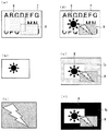
図1に、本発明の実施の形態に係る画像合成装置の回路構成を示す。また、図2に、ベース画像、オーバーレイ画像等の一例を示す。本実施の形態における画像合成装置は、ベース画像入力端子1aからベース画像信号として入力されるベース画像7(図2(a))のクロマキー色で塗られた領域に、オーバーレイ画像を重ねて合成画像として、合成画像出力端子6aに出力する。
<Overall configuration>
FIG. 1 shows a circuit configuration of an image composition apparatus according to an embodiment of the present invention. FIG. 2 shows an example of a base image, an overlay image, and the like. The image composition apparatus according to the present embodiment superimposes an overlay image on an area painted in chroma key color of a base image 7 (FIG. 2A) input as a base image signal from a base
クロマキー色の領域は、例えば、第1のウインドウ領域8と第2のウインドウ領域9から構成され、第1のウインドウ領域8には、第1のオーバーレイ画像入力端子2aから入力される第1のオーバーレイ画像(図2(b))が所定のサイズに拡大縮小して重ねられ、第2のウインドウ領域9には、第2のオーバーレイ画像入力端子3aから入力される第2のオーバーレイ画像(図2(c))が所定のサイズに拡大縮小して重ねられて、合成画像(図2(d))となる。合成画像の出力先は、例えば、PCのディスプレイなどの表示装置(図示せず)である。
The chroma key color area is composed of, for example, a
また、本実施の形態の画像合成装置は、後述するように、機器の故障等でベース画像信号が無信号になった場合であっても、少なくとも、所定のサイズに拡大縮小した第1のオーバーレイ画像および第2のオーバーレイ画像の出力を行うものである。 In addition, as will be described later, the image composition apparatus according to the present embodiment includes at least a first overlay that is enlarged or reduced to a predetermined size even when the base image signal becomes no signal due to equipment failure or the like. An image and a second overlay image are output.
なお、図2(a)に一例として示したベース画像は、例えばPCのデスクトップ画像であり、図中の破線は、各ウインドウ領域を示すためのもので、実際のベース画像には描かれていない。 Note that the base image shown as an example in FIG. 2A is a desktop image of a PC, for example, and the broken lines in the figure are for showing each window area and are not drawn in the actual base image. .
本実施の形態における画像合成装置は、図1に示すように、ベース画像のクロマキー色の部分の判定を行うクロマキー判定手段としてのクロマキー判定回路4と、ベース画像を処理して所定の信号を出力するベース画像処理回路1と、オーバーレイ画像処理部と、出力する画像信号を選択するセレクタ回路6、セレクタ回路6を制御するセレクタ制御回路5を備える。
As shown in FIG. 1, the image composition apparatus according to the present embodiment processes a base key and outputs a predetermined signal by processing a base key image and a chroma
オーバーレイ画像処理部は、第1のオーバーレイ画像を処理する第1のオーバーレイ画像処理回路2と、第2のオーバーレイ画像を処理する第2のオーバーレイ画像処理回路3とで構成される。
The overlay image processing unit includes a first overlay
<ベース画像処理回路の構成>
図3に、ベース画像処理回路1の構成を示す。ベース画像処理回路1は、ベース画像の有無の判定を行うベース画像有無判定手段としてのベース画像無し検出回路11と、入力されたベース画像信号を遅延させる遅延回路12と、同期信号回路部からなる。
<Configuration of base image processing circuit>
FIG. 3 shows the configuration of the base image processing circuit 1. The base image processing circuit 1 includes a base image
同期信号回路部は、ベース画像信号から映像同期信号を分離して、第1の映像同期信号13aとして出力する同期信号分離回路13と、予め用意された第2の映像同期信号を出力する同期信号生成回路14と、ベース画像無し信号1cに基づいて第1の映像同期信号13aと第2の映像同期信号14aのいずれかを選択して映像同期信号1dとして出力する、同期信号セレクタ回路15とから構成される。
The synchronization signal circuit unit separates the video synchronization signal from the base image signal and outputs it as the first video synchronization signal 13a, and the synchronization signal that outputs the second video synchronization signal prepared in advance. From the
<第1のオーバーレイ画像処理回路の構成>
図4に、第1のオーバーレイ画像処理回路2の構成を示す。第1のオーバーレイ画像処理回路2は、映像同期信号1dに従って第1のオーバーレイ画像信号を同期させてフレームレート変換するフレームレート変換回路21と、第1のオーバーレイ画像を表示する領域、即ち第1のウインドウ領域8の位置およびサイズを記憶する記憶手段としての第1のウインドウ位置・サイズレジスタ23と、第1のウインドウ位置・サイズレジスタ23の情報に従って、第1のオーバーレイ画像の位置およびサイズを変更する画像位置サイズ変更手段としての拡大縮小回路22を備える。
<Configuration of First Overlay Image Processing Circuit>
FIG. 4 shows the configuration of the first overlay
なお、第2のオーバーレイ画像処理回路3は、第1のオーバーレイ画像処理回路2と同様に、フレームレート変換回路、拡大縮小回路および第2のウインドウ位置・サイズレジスタを備える。ここで、第2のウインドウ位置・サイズレジスタには、第2のウインドウ領域9の位置およびサイズが記憶されている。
Similar to the first overlay
<セレクタ制御回路の構成>
図5に、セレクタ制御回路5の構成を示す。セレクタ制御回路5は、セレクタ回路6を切り替えるためのセレクタ切替信号5aを生成する、セレクタ切替信号生成回路51と、ウインドウの優先順位情報が記憶されたウインドウ優先順位レジスタ52と、オーバーレイ画像を表示する領域(即ち、第1のウインドウ領域8および第2のウインドウ領域9)の位置およびサイズを記憶する記憶手段としてのウインドウ位置・サイズレジスタ53を備える。ここで、前記優先順位情報とは、複数のウインドウ領域のうち、いずれのウインドウ領域のオーバーレイ画像を優先して表示するかを示す情報である。
<Configuration of selector control circuit>
FIG. 5 shows the configuration of the
<ベース画像処理回路の動作>
ベース画像入力端子1aから入力されたベース画像信号は、ベース画像無し検出回路11、遅延回路12、同期信号分離回路13にそれぞれ入力される。ベース画像無し検出回路11は、ベース画像の有無を判定し、その判定結果をベース画像無し信号1cとして、遅延回路12、同期信号セレクタ回路15、およびセレクタ制御回路5へ出力する。
<Operation of base image processing circuit>
The base image signal input from the base
遅延回路12は、ベース画像信号を一定時間遅延させてから、ベース画像出力端子1bへ出力する。この遅延は、クロマキー判定回路4における信号の遅延およびセレクタ制御回路5における信号の遅延を考慮したものである。この遅延を行うことで、セレクタ回路6において、適切なタイミングでベース画像出力端子1bの選択・非選択の切り替えを行うことができる。
The
また、遅延回路12には、ベース画像無し信号1cが入力されており、ベース画像無し信号1cがベース画像無しを示す場合は、遅延回路12に予め保存された背景画像7aを、ベース画像の代わりにベース画像出力端子1bに出力する。この場合の合成画像の一例を図2(e)に示す。
When the base image absence signal 1c is input to the
同期信号分離回路13は、ベース画像信号から映像同期信号を分離して、第1の映像同期信号13aとして同期信号セレクタ回路15へ入力する。また、同期信号生成回路14は、予め用意された映像同期信号を、第2の映像同期信号14aとして同期信号セレクタ回路15へ入力する。
The synchronization signal separation circuit 13 separates the video synchronization signal from the base image signal and inputs it to the synchronization
同期信号セレクタ回路15は、ベース画像無し信号1cに基づいて、第1の映像同期信号13aもしくは第2の映像同期信号14aを選択する。即ちベース画像無し信号1cがベース画像有りを示す場合は、第1の映像同期信号13aを選択し、一方ベース画像無し信号1cがベース画像無しを示す場合は、第2の映像同期信号14aを選択して、映像同期信号1dとして第1のオーバーレイ処理回路2、第2のオーバーレイ処理回路3およびセレクタ制御回路5へ出力する。
The synchronization
<第1のオーバーレイ画像処理回路の動作>
第1のオーバーレイ画像信号が、第1のオーバーレイ画像信号入力端子2aからフレームレート変換回路21に入力されると、フレームレート変換回路21は第1のオーバーレイ画像信号を映像同期信号1dに同期させてフレームレート変換を行い、拡大縮小回路22に出力する。拡大縮小回路22は、第1のウインドウ位置・サイズレジスタ23の情報に従って、第1のオーバーレイ画像の所定の部分を切り出し、所定のサイズに拡大または縮小して、第1のオーバーレイ画像出力端子2bに出力する。ここで、第1のオーバーレイ画像出力端子2bに出力するタイミングは、映像同期信号1dに従って決められる。
<Operation of First Overlay Image Processing Circuit>
When the first overlay image signal is input from the first overlay image
また、第2のオーバーレイ画像処理回路3は、第2のオーバーレイ画像入力端子3aから入力される第2のオーバーレイ画像信号に対して、第1のオーバーレイ画像処理回路2と同様の処理を行い、第2のオーバーレイ画像出力端子3bに出力する。
The second overlay image processing circuit 3 performs the same processing as the first overlay
<クロマキー判定回路の動作>
クロマキー判定回路4は、ベース画像入力端子1aから入力されたベース画像信号から、ベース画像のクロマキー色の部分を検出して、クロマキー色の領域であることを示すクロマキー信号4aを、セレクタ制御回路5へ出力する。
<Operation of chroma key determination circuit>
The chroma
<セレクタ制御回路およびセレクタ回路の動作>
セレクタ制御回路5には、クロマキー信号4a、ベース画像無し信号1c、および映像同期信号1dが入力される。セレクタ切替信号生成回路51は、これらの信号に従い、ウインドウ優先順位レジスタ52およびウインドウ位置・サイズレジスタ53の情報を参照してセレクタ切替信号5aを生成し、セレクタ回路6に出力する。
<Operation of selector control circuit and selector circuit>
The
セレクタ回路6は、セレクタ切替信号5aに従って、ベース画像出力端子1b、第1のオーバーレイ画像出力端子2b、第2のオーバーレイ画像出力端子3bのいずれかの端子を選択しながら、合成画像出力端子6aに合成画像信号を出力する。
The
以下で、ベース画像無し信号1cがベース画像有りを示す場合と、ベース画像無しを示す場合とに分けて、セレクタ制御回路5の動作を説明する。
Hereinafter, the operation of the
<ベース画像信号が有る場合>
ベース画像無し信号1cがベース画像有りを示す場合、即ちベース画像信号が有る場合には、ベース画像信号から分離された第1の同期信号13aを映像同期信号1dとして用いて、クロマキー信号4aを参照しながら制御を行う。
<When there is a base image signal>
When the base image absence signal 1c indicates the presence of a base image, that is, when there is a base image signal, the chroma key signal 4a is referred to using the first synchronization signal 13a separated from the base image signal as the video synchronization signal 1d. Control.
クロマキー信号4aがクロマキー色の部分を示す場合、映像同期信号1dを基準として決まる領域が、2つのウインドウが重なる領域、即ち第1のウインドウ領域8と第2のウインドウ領域9が重なる領域である場合には、ウインドウ優先順位レジスタ52を参照して、セレクタ回路6が、優先順位の高い方のオーバーレイ画像のオーバーレイ画像出力端子を選択するように、セレクタ切替信号5aを出力する。また、映像同期信号1dを基準として決まる領域が、第1のウインドウ領域8であって、2つのウインドウが重なる領域でない場合には、セレクタ回路6が第1のオーバーレイ画像出力端子2bを選択するように、セレクタ切替信号5aを出力する。また、映像同期信号1dを基準として決まる領域が、第2のウインドウ領域9であって、2つのウインドウが重なる領域でない場合には、セレクタ回路6が第2のオーバーレイ画像出力端子3bを選択するように、セレクタ切替信号5aを出力する。
When the chroma key signal 4a indicates a chroma key color portion, a region determined based on the video synchronization signal 1d is a region where two windows overlap, that is, a region where the
一方、クロマキー信号4aがクロマキー色の部分を示していない場合には、セレクタ回路6が、ベース画像出力端子1bを選択するようにセレクタ切替信号5aを出力する。
On the other hand, when the chroma key signal 4a does not indicate the chroma key color portion, the
以上の様にしてセレクタ回路6を制御することで、合成画像出力端子6aから合成画像(例えば、図2(d))が出力される。この合成画像の例では、第2のオーバーレイ画像の方が、第1のオーバーレイ画像よりも優先順位が高く設定されているので、2つのウインドウが重なる領域には第2のオーバーレイ画像が表示される。
By controlling the
<ベース画像信号が無信号の場合>
ベース画像無し信号1cがベース画像無しを示す場合、即ちベース画像信号が無信号の場合には、セレクタ制御回路5は、同期信号生成回路14から出力される、予め用意された第2の映像同期信号14aを映像同期信号1dとして用いて、セレクタ回路6の制御を行う。
<When base image signal is no signal>
When the base image absence signal 1c indicates that there is no base image, that is, when the base image signal is no signal, the
映像同期信号1dを基準として決まる領域に対して、ウインドウ位置・サイズレジスタ53の情報を参照してセレクタ切替信号5aを出力する。即ち、映像同期信号1dを基準として決まる領域が、2つのウインドウが重なる領域、即ち第1のウインドウ領域8と第2のウインドウ領域9が重なる領域である場合には、ウインドウ優先順位レジスタ52を参照して、セレクタ回路6が、優先順位の高い方のオーバーレイ画像のオーバーレイ画像出力端子を選択するように、セレクタ制御信号5aを出力する。
The selector switching signal 5a is output with reference to the information in the window position /
また、映像同期信号1dを基準として決まる領域が、第1のウインドウ領域8であって、2つのウインドウが重なる領域でない場合には、セレクタ回路6が第1のオーバーレイ画像出力端子2bを選択するように、セレクタ切替信号5aを出力する。
If the area determined based on the video synchronization signal 1d is the
また、映像同期信号1dを基準として決まる領域が、第2のウインドウ領域9であって、2つのウインドウが重なる領域でない場合には、セレクタ回路6が第2のオーバーレイ画像出力端子3bを選択するように、セレクタ切替信号5aを出力する。
If the area determined based on the video synchronization signal 1d is the
また、映像同期信号1dを基準として決まる領域が、第1のウインドウ領域8でも第2のウインドウ領域9でもない場合には、ベース画像出力端子1bを選択するように、セレクタ切替信号5aを出力する。
In addition, when the region determined based on the video synchronization signal 1d is neither the
以上で述べたようにセレクタ回路6を制御して、合成画像出力端子6aから合成画像信号を出力する。ベース画像信号が無信号の場合の合成画像の一例を図2(e)に示す。本実施の形態においては、ベース画像信号が無信号となった場合には、予め用意された背景画像7aが、ベース画像7の代わりとして遅延回路12からベース画像出力端子1bに出力される。従って、図2(e)のように、ベース画像7が無い場合でも、オーバーレイ画像の背景に背景画像7aが表示される。
As described above, the
一方、遅延回路12が背景画像7aを出力しない場合には、図2(f)に示すように、オーバーレイ画像のみが出力され、オーバーレイ画像の背景には、例えば黒色のラスタ画面7bの様な画像が表示される。
On the other hand, when the
なお、本実施の形態においては、オーバーレイ画像数を2系統としたが、必ずしも2系統である必要はなく、任意の系統数としてよい。 In this embodiment, the number of overlay images is two. However, the number of overlay images is not necessarily two, and may be any number.
<効果>
本実施の形態における画像合成装置は、ベース画像7上のクロマキー色の領域にオーバーレイ画像を重ね合わせて合成画像として出力する画像合成装置であって、オーバーレイ画像を表示する領域の位置およびサイズを記憶する記憶手段と、記憶手段の情報に従って、オーバーレイ画像の位置およびサイズを変更する画像位置・サイズ変更手段と、ベース画像7の有無の判定を行うベース画像有無判定手段と、ベース画像7のクロマキー色部分の判定を行うクロマキー判定手段とを備え、ベース画像有無判定手段によりベース画像ありと判定され、かつ、クロマキー判定手段により、クロマキー色部分であると判定された場合は、画像位置・サイズ変更手段により位置およびサイズが変更されたオーバーレイ画像を出力し、ベース画像有無判定手段によりベース画像ありと判定され、かつ、クロマキー判定手段により、クロマキー色部分でないと判定された場合は、ベース画像7を出力し、ベース画像有無判定手段により、ベース画像なしと判定された場合は、画像位置・サイズ変更手段により位置およびサイズが変更されたオーバーレイ画像を出力することを特徴とする。
<Effect>
The image composition apparatus according to the present embodiment is an image composition apparatus that superimposes an overlay image on a chroma key color area on a base image 7 and outputs the image as a composite image, and stores the position and size of the area in which the overlay image is displayed. Storing means, an image position / size changing means for changing the position and size of the overlay image in accordance with information in the storing means, a base image presence / absence determining means for determining presence / absence of the base image 7, and a chroma key color of the base image 7 A chroma key determining means for determining a portion, and if the base image presence / absence determining means determines that there is a base image and if the chroma key determining means determines that it is a chroma key color part, the image position / size changing means position and size outputs the overlay image that has been changed, the base image presence-size It is determined that there is the base image by means and by chromakey judgment means, if it is determined not to be chromakey color portion, and outputs the base image 7, the base image presence determining means, when it is determined that no base image An overlay image whose position and size have been changed by the image position / size changing means is output.
従って、ベース画像有無判定手段によりベース画像無しと判定された場合でも、画像位置・サイズ変更手段により位置およびサイズが変更されたオーバーレイ画像を出力するため、機器の故障等で、ベース画像信号が無信号となった場合でも、継続してオーバーレイ画像の出力を行うことが可能である。 Therefore, even when the base image presence / absence determining means determines that there is no base image, the overlay image whose position and size have been changed by the image position / size changing means is output. Even when it becomes a signal, it is possible to continuously output an overlay image.
また、本実施の形態における画像合成装置は、ベース画像有無判定手段により、ベース画像なしと判定された場合は、ベース画像の信号から取得していた第1の映像同期信号13aに代えて、予め用意された第2の映像同期信号14aを使用して、オーバーレイ画像を出力することを特徴とする。
In addition, in the image composition device according to the present embodiment, when the base image presence / absence determining unit determines that there is no base image, the image synthesizing device replaces the first video synchronization signal 13a acquired from the base image signal in advance. An overlay image is output using the prepared second
従って、ベース画像信号が無信号となり、ベース画像信号から第1の映像同期信号13aを取得できない場合であっても、その代わりに、予め用意された第2の同期信号14aを映像同期信号1dとして用いることにより、オーバーレイ画像の出力を続けることが可能である。
Therefore, even if the base image signal is no signal and the first video synchronization signal 13a cannot be obtained from the base image signal, the
また、本実施の形態における画像合成装置は、ベース画像有無判定手段としてのベース画像無し検出回路11により、ベース画像なしと判定された場合は、予め保存されている画像を背景画像7aとして、ベース画像に代えて出力することを特徴とする。
Further, in the image composition device according to the present embodiment, when it is determined that there is no base image by the base image
従って、ベース画像信号が無信号となった場合には、ベース画像の代わりに、遅延回路12に予め保存されている背景画像7aを出力することで、オーバーレイ画像の背景に、例えば、ベース画像が無信号になったことを知らせる色、文字、図形等の情報を含む画像を表示することが可能である。
Therefore, when the base image signal becomes no signal, by outputting the
なお、本発明は、その発明の範囲内において、実施の形態を適宜、変形、省略することが可能である。 In the present invention, the embodiments can be appropriately modified and omitted within the scope of the invention.
1 ベース画像処理回路、1a ベース画像入力端子、1b ベース画像出力端子、1c ベース画像無し信号、1d 映像同期信号、2 第1のオーバーレイ画像処理回路、2a 第1のオーバーレイ画像入力端子、2b 第1のオーバーレイ画像出力端子、3 第2のオーバーレイ画像処理回路、3a 第2のオーバーレイ画像入力端子、3b 第2のオーバーレイ画像出力端子、4 クロマキー判定回路、4a クロマキー信号、5 セレクタ制御回路、5a セレクタ切替信号、6 セレクタ回路、6a 合成画像出力端子、11 ベース画像無し検出回路、12 遅延回路、13 同期信号分離回路、13 第1の同期信号、14 同期信号生成回路、14a 第2の同期信号、15 同期信号セレクタ回路、21 フレームレート変換回路、22 拡大縮小回路、23 第1のウインドウ位置・サイズレジスタ、51 セレクタ切替信号生成回路、52 ウインドウ優先順位レジスタ、53 ウインドウ位置・サイズレジスタ、7 ベース画像、7a 背景画像、7b ラスタ画面、8 第1のウインドウ領域、9 第2のウインドウ領域。 DESCRIPTION OF SYMBOLS 1 Base image processing circuit, 1a Base image input terminal, 1b Base image output terminal, 1c No base image signal, 1d Video synchronization signal, 2 First overlay image processing circuit, 2a First overlay image input terminal, 2b First Overlay image output terminal, 3 second overlay image processing circuit, 3a second overlay image input terminal, 3b second overlay image output terminal, 4 chroma key determination circuit, 4a chroma key signal, 5 selector control circuit, 5a selector switching Signal, 6 selector circuit, 6a composite image output terminal, 11 base image absence detection circuit, 12 delay circuit, 13 synchronization signal separation circuit, 13 first synchronization signal, 14 synchronization signal generation circuit, 14a second synchronization signal, 15 Synchronization signal selector circuit, 21 frame rate conversion circuit, 22 Enlargement / reduction circuit, 23 First window position / size register, 51 Selector switching signal generation circuit, 52 Window priority order register, 53 Window position / size register, 7 Base image, 7a Background image, 7b Raster screen, 8 First Window area, 9 Second window area.
Claims (3)
前記オーバーレイ画像を表示する領域の位置およびサイズを記憶する記憶手段と、
前記記憶手段の情報に従って、前記オーバーレイ画像の位置およびサイズを変更する画像位置・サイズ変更手段と、
前記ベース画像の有無の判定を行うベース画像有無判定手段と、
前記ベース画像のクロマキー色部分の判定を行うクロマキー判定手段と、
前記合成画像出力端子への前記ベース画像および前記オーバーレイ画像の出力を制御する制御回路と、
を備え、
前記ベース画像有無判定手段によりベース画像有りと判定され、かつ、前記クロマキー判定手段により、クロマキー色部分であると判定された場合は、前記制御回路が、前記画像位置・サイズ変更手段により位置およびサイズが変更された前記オーバーレイ画像を前記合成画像出力端子に出力するように制御を行い、
前記ベース画像有無判定手段によりベース画像有りと判定され、かつ、前記クロマキー判定手段により、クロマキー色部分でないと判定された場合は、前記制御回路が、前記ベース画像を前記合成画像出力端子に出力するように制御を行い、
前記ベース画像有無判定手段により、ベース画像無しと判定された場合は、前記制御回路が、前記画像位置・サイズ変更手段により位置およびサイズが変更された前記オーバーレイ画像を前記合成画像出力端子に出力するように制御を行うことを特徴とする、
画像合成装置。 An image composition device that superimposes an overlay image on a chroma key color region on a base image and outputs a composite image to a composite image output terminal ,
Storage means for storing the position and size of the area for displaying the overlay image;
Image position / size changing means for changing the position and size of the overlay image according to the information of the storage means;
Base image presence / absence determining means for determining presence or absence of the base image;
Chroma key determination means for determining a chroma key color portion of the base image;
A control circuit for controlling the output of the base image and the overlay image to the composite image output terminal;
With
When it is determined that the base image is present by the base image presence / absence determining means, and the chroma key determining means determines that it is a chroma key color portion, the control circuit determines the position and size by the image position / size changing means. Is controlled to output the overlay image that has been changed to the composite image output terminal ,
When it is determined that the base image is present by the base image presence / absence determining means, and the chroma key determining means determines that it is not a chroma key color portion, the control circuit outputs the base image to the composite image output terminal . Control as
When the base image presence / absence determining unit determines that there is no base image, the control circuit outputs the overlay image whose position and size have been changed by the image position / size changing unit to the composite image output terminal . It is characterized by performing control as
Image composition device.
請求項1に記載の画像合成装置。 When the base image presence / absence determining unit determines that there is no base image, the control circuit uses a video synchronization signal prepared in advance instead of the video synchronization signal acquired from the signal of the base image. And controlling to output the overlay image to the composite image output terminal ,
The image composition device according to claim 1.
請求項1または2に記載の画像合成装置。 When the base image presence / absence determining unit determines that there is no base image , the image composition device outputs the composite image instead of the image stored in advance in the circuit inside the image composition device. Output to the terminal ,
The image composition device according to claim 1.
Priority Applications (5)
| Application Number | Priority Date | Filing Date | Title |
|---|---|---|---|
| JP2012051291A JP5875415B2 (en) | 2012-03-08 | 2012-03-08 | Image synthesizer |
| US13/720,619 US9613597B2 (en) | 2012-03-08 | 2012-12-19 | Apparatus and method for image compositing based on detected presence or absence of base image |
| EP13150453.2A EP2637411B1 (en) | 2012-03-08 | 2013-01-08 | Image compositing apparatus |
| CN201310049013.3A CN103313069B (en) | 2012-03-08 | 2013-02-07 | Image synthesizer |
| RU2013107805/08A RU2517266C1 (en) | 2012-03-08 | 2013-02-21 | Image construction device |
Applications Claiming Priority (1)
| Application Number | Priority Date | Filing Date | Title |
|---|---|---|---|
| JP2012051291A JP5875415B2 (en) | 2012-03-08 | 2012-03-08 | Image synthesizer |
Publications (3)
| Publication Number | Publication Date |
|---|---|
| JP2013187732A JP2013187732A (en) | 2013-09-19 |
| JP2013187732A5 JP2013187732A5 (en) | 2015-02-26 |
| JP5875415B2 true JP5875415B2 (en) | 2016-03-02 |
Family
ID=47630148
Family Applications (1)
| Application Number | Title | Priority Date | Filing Date |
|---|---|---|---|
| JP2012051291A Expired - Fee Related JP5875415B2 (en) | 2012-03-08 | 2012-03-08 | Image synthesizer |
Country Status (5)
| Country | Link |
|---|---|
| US (1) | US9613597B2 (en) |
| EP (1) | EP2637411B1 (en) |
| JP (1) | JP5875415B2 (en) |
| CN (1) | CN103313069B (en) |
| RU (1) | RU2517266C1 (en) |
Cited By (1)
| Publication number | Priority date | Publication date | Assignee | Title |
|---|---|---|---|---|
| JP2014137431A (en) * | 2013-01-16 | 2014-07-28 | Mitsubishi Electric Corp | Image display system |
Families Citing this family (5)
| Publication number | Priority date | Publication date | Assignee | Title |
|---|---|---|---|---|
| KR20140111736A (en) * | 2013-03-12 | 2014-09-22 | 삼성전자주식회사 | Display apparatus and control method thereof |
| CN104900204B (en) * | 2015-06-12 | 2017-05-17 | 武汉精测电子技术股份有限公司 | Logic frame overlapping device and method based on FPGA |
| US10386478B2 (en) * | 2016-05-18 | 2019-08-20 | International Business Machines Corporation | Range-independent resolution radar |
| RU190639U1 (en) * | 2019-04-04 | 2019-07-05 | Акционерное общество Научно-производственный центр "Электронные вычислительно-информационные системы" | SYSTEM OF GENERATION OF IMAGES CONTAINING TEXT |
| RU2717787C1 (en) * | 2019-04-04 | 2020-03-26 | Акционерное общество Научно-производственный центр "Электронные вычислительно-информационные системы" | System and method of generating images containing text |
Family Cites Families (15)
| Publication number | Priority date | Publication date | Assignee | Title |
|---|---|---|---|---|
| US4827344A (en) * | 1985-02-28 | 1989-05-02 | Intel Corporation | Apparatus for inserting part of one video image into another video image |
| US5241371A (en) * | 1991-10-30 | 1993-08-31 | Pioneer Electronic Corporation | Image display control apparatus and still picture reproducing system |
| JPH05207368A (en) | 1992-01-27 | 1993-08-13 | Hitachi Ltd | Overlap display device |
| IL109487A (en) * | 1994-04-29 | 1996-09-12 | Orad Hi Tec Systems Ltd | Chromakeying system |
| JP2000221960A (en) * | 1999-02-03 | 2000-08-11 | Mitsubishi Electric Corp | Overlay device |
| US8698840B2 (en) | 1999-03-05 | 2014-04-15 | Csr Technology Inc. | Method and apparatus for processing video and graphics data to create a composite output image having independent and separate layers of video and graphics display planes |
| US6903753B1 (en) * | 2000-10-31 | 2005-06-07 | Microsoft Corporation | Compositing images from multiple sources |
| JP2002271692A (en) | 2001-03-13 | 2002-09-20 | Canon Inc | Image processing method, image processing unit, studio apparatus, studio system and program |
| JP4855930B2 (en) * | 2003-05-02 | 2012-01-18 | アラン ロバート ステイカー、 | Interactive system and method for video composition |
| JP2004355391A (en) | 2003-05-29 | 2004-12-16 | Hitachi Ltd | Large screen supervision and control system |
| RU2282946C2 (en) * | 2003-12-25 | 2006-08-27 | Александр Александрович Сухов | Method for transferring visual information |
| JP2006129401A (en) | 2004-11-01 | 2006-05-18 | Matsushita Electric Ind Co Ltd | Image processing apparatus |
| JP2006222694A (en) | 2005-02-09 | 2006-08-24 | Yamaha Corp | Data processor and program for informing user of standing position |
| JP4939811B2 (en) | 2006-02-02 | 2012-05-30 | 三菱電機株式会社 | Image display device |
| RU2426172C1 (en) * | 2010-01-21 | 2011-08-10 | Корпорация "САМСУНГ ЭЛЕКТРОНИКС Ко., Лтд." | Method and system for isolating foreground object image proceeding from colour and depth data |
-
2012
- 2012-03-08 JP JP2012051291A patent/JP5875415B2/en not_active Expired - Fee Related
- 2012-12-19 US US13/720,619 patent/US9613597B2/en active Active
-
2013
- 2013-01-08 EP EP13150453.2A patent/EP2637411B1/en not_active Not-in-force
- 2013-02-07 CN CN201310049013.3A patent/CN103313069B/en not_active Expired - Fee Related
- 2013-02-21 RU RU2013107805/08A patent/RU2517266C1/en active
Cited By (1)
| Publication number | Priority date | Publication date | Assignee | Title |
|---|---|---|---|---|
| JP2014137431A (en) * | 2013-01-16 | 2014-07-28 | Mitsubishi Electric Corp | Image display system |
Also Published As
| Publication number | Publication date |
|---|---|
| CN103313069A (en) | 2013-09-18 |
| CN103313069B (en) | 2015-10-07 |
| US20130235059A1 (en) | 2013-09-12 |
| EP2637411A3 (en) | 2014-02-26 |
| JP2013187732A (en) | 2013-09-19 |
| US9613597B2 (en) | 2017-04-04 |
| RU2517266C1 (en) | 2014-05-27 |
| EP2637411B1 (en) | 2017-06-21 |
| EP2637411A2 (en) | 2013-09-11 |
Similar Documents
| Publication | Publication Date | Title |
|---|---|---|
| JP5875415B2 (en) | Image synthesizer | |
| US10733963B2 (en) | Information processing apparatus and image processing method | |
| JPWO2013175735A1 (en) | Display control apparatus and display control method | |
| JP2008244981A (en) | Video synthesis device and video output device | |
| JP2013187732A5 (en) | ||
| WO2017217011A1 (en) | Image processing device, and superimposed image generation method | |
| JP2005043695A (en) | Screen display apparatus | |
| JP2009276557A (en) | Video processing device, video processing lsi, display, car navigation system, mixing ratio information generating method, program, and recording medium | |
| JP5765963B2 (en) | Image processing apparatus and image processing method | |
| JP2016128893A (en) | Image processing device and image processing method | |
| JP2013171054A (en) | Display control device and display control method | |
| JP2006301029A (en) | On-screen display apparatus and on-screen display creating method | |
| JP2006303631A (en) | On-screen display device and on-screen display generation method | |
| JP5219646B2 (en) | Video processing apparatus and video processing apparatus control method | |
| JP4466117B2 (en) | Image synthesizer | |
| JP4565903B2 (en) | On-screen display device | |
| JP6470136B2 (en) | Screen image generator | |
| JP2005215557A (en) | Display device and method | |
| JP2010123067A (en) | Display controller and display control program | |
| JP2008191474A (en) | On-screen display circuit | |
| JP6622562B2 (en) | Information processing terminal | |
| JP2005338864A (en) | Image display device | |
| JP2008262102A (en) | Overlay image synthesizer | |
| JP2006350374A (en) | Image display apparatus | |
| KR20070079826A (en) | Display apparatus |
Legal Events
| Date | Code | Title | Description |
|---|---|---|---|
| A521 | Request for written amendment filed |
Free format text: JAPANESE INTERMEDIATE CODE: A523 Effective date: 20150107 |
|
| A621 | Written request for application examination |
Free format text: JAPANESE INTERMEDIATE CODE: A621 Effective date: 20150107 |
|
| A131 | Notification of reasons for refusal |
Free format text: JAPANESE INTERMEDIATE CODE: A131 Effective date: 20151020 |
|
| A521 | Request for written amendment filed |
Free format text: JAPANESE INTERMEDIATE CODE: A523 Effective date: 20151202 |
|
| TRDD | Decision of grant or rejection written | ||
| A01 | Written decision to grant a patent or to grant a registration (utility model) |
Free format text: JAPANESE INTERMEDIATE CODE: A01 Effective date: 20151222 |
|
| A61 | First payment of annual fees (during grant procedure) |
Free format text: JAPANESE INTERMEDIATE CODE: A61 Effective date: 20160119 |
|
| R150 | Certificate of patent or registration of utility model |
Ref document number: 5875415 Country of ref document: JP Free format text: JAPANESE INTERMEDIATE CODE: R150 |
|
| R250 | Receipt of annual fees |
Free format text: JAPANESE INTERMEDIATE CODE: R250 |
|
| R250 | Receipt of annual fees |
Free format text: JAPANESE INTERMEDIATE CODE: R250 |
|
| R250 | Receipt of annual fees |
Free format text: JAPANESE INTERMEDIATE CODE: R250 |
|
| LAPS | Cancellation because of no payment of annual fees |