JP5865287B2 - Electronic device and control method of electronic device - Google Patents
Electronic device and control method of electronic device Download PDFInfo
- Publication number
- JP5865287B2 JP5865287B2 JP2013073874A JP2013073874A JP5865287B2 JP 5865287 B2 JP5865287 B2 JP 5865287B2 JP 2013073874 A JP2013073874 A JP 2013073874A JP 2013073874 A JP2013073874 A JP 2013073874A JP 5865287 B2 JP5865287 B2 JP 5865287B2
- Authority
- JP
- Japan
- Prior art keywords
- electrode
- data
- detection
- application processor
- sensor
- Prior art date
- Legal status (The legal status is an assumption and is not a legal conclusion. Google has not performed a legal analysis and makes no representation as to the accuracy of the status listed.)
- Active
Links
- 238000000034 method Methods 0.000 title claims description 13
- 238000001514 detection method Methods 0.000 claims description 120
- 238000012545 processing Methods 0.000 claims description 48
- 230000004044 response Effects 0.000 claims description 8
- 239000011159 matrix material Substances 0.000 claims description 7
- 239000000758 substrate Substances 0.000 description 28
- 239000008186 active pharmaceutical agent Substances 0.000 description 25
- 238000010586 diagram Methods 0.000 description 13
- 239000004973 liquid crystal related substance Substances 0.000 description 8
- 239000003990 capacitor Substances 0.000 description 5
- 238000004891 communication Methods 0.000 description 5
- 101100224481 Dictyostelium discoideum pole gene Proteins 0.000 description 4
- 101150046160 POL1 gene Proteins 0.000 description 4
- 101150110488 POL2 gene Proteins 0.000 description 4
- 101100117436 Thermus aquaticus polA gene Proteins 0.000 description 4
- 239000000463 material Substances 0.000 description 4
- 239000011347 resin Substances 0.000 description 4
- 229920005989 resin Polymers 0.000 description 4
- 230000005684 electric field Effects 0.000 description 3
- 239000007772 electrode material Substances 0.000 description 3
- 239000003086 colorant Substances 0.000 description 2
- 239000011521 glass Substances 0.000 description 2
- 238000012546 transfer Methods 0.000 description 2
- 230000002950 deficient Effects 0.000 description 1
- 238000007599 discharging Methods 0.000 description 1
- 238000005401 electroluminescence Methods 0.000 description 1
- AMGQUBHHOARCQH-UHFFFAOYSA-N indium;oxotin Chemical compound [In].[Sn]=O AMGQUBHHOARCQH-UHFFFAOYSA-N 0.000 description 1
- 238000012986 modification Methods 0.000 description 1
- 230000004048 modification Effects 0.000 description 1
- 230000010287 polarization Effects 0.000 description 1
- 239000004065 semiconductor Substances 0.000 description 1
- YVTHLONGBIQYBO-UHFFFAOYSA-N zinc indium(3+) oxygen(2-) Chemical compound [O--].[Zn++].[In+3] YVTHLONGBIQYBO-UHFFFAOYSA-N 0.000 description 1
Images


Classifications
-
- G—PHYSICS
- G06—COMPUTING; CALCULATING OR COUNTING
- G06F—ELECTRIC DIGITAL DATA PROCESSING
- G06F3/00—Input arrangements for transferring data to be processed into a form capable of being handled by the computer; Output arrangements for transferring data from processing unit to output unit, e.g. interface arrangements
- G06F3/01—Input arrangements or combined input and output arrangements for interaction between user and computer
- G06F3/03—Arrangements for converting the position or the displacement of a member into a coded form
- G06F3/041—Digitisers, e.g. for touch screens or touch pads, characterised by the transducing means
- G06F3/0412—Digitisers structurally integrated in a display
-
- G—PHYSICS
- G06—COMPUTING; CALCULATING OR COUNTING
- G06F—ELECTRIC DIGITAL DATA PROCESSING
- G06F3/00—Input arrangements for transferring data to be processed into a form capable of being handled by the computer; Output arrangements for transferring data from processing unit to output unit, e.g. interface arrangements
- G06F3/01—Input arrangements or combined input and output arrangements for interaction between user and computer
- G06F3/03—Arrangements for converting the position or the displacement of a member into a coded form
- G06F3/041—Digitisers, e.g. for touch screens or touch pads, characterised by the transducing means
- G06F3/0416—Control or interface arrangements specially adapted for digitisers
- G06F3/04166—Details of scanning methods, e.g. sampling time, grouping of sub areas or time sharing with display driving
-
- G—PHYSICS
- G06—COMPUTING; CALCULATING OR COUNTING
- G06F—ELECTRIC DIGITAL DATA PROCESSING
- G06F3/00—Input arrangements for transferring data to be processed into a form capable of being handled by the computer; Output arrangements for transferring data from processing unit to output unit, e.g. interface arrangements
- G06F3/01—Input arrangements or combined input and output arrangements for interaction between user and computer
- G06F3/03—Arrangements for converting the position or the displacement of a member into a coded form
- G06F3/041—Digitisers, e.g. for touch screens or touch pads, characterised by the transducing means
- G06F3/0416—Control or interface arrangements specially adapted for digitisers
- G06F3/0418—Control or interface arrangements specially adapted for digitisers for error correction or compensation, e.g. based on parallax, calibration or alignment
- G06F3/04184—Synchronisation with the driving of the display or the backlighting unit to avoid interferences generated internally
-
- G—PHYSICS
- G06—COMPUTING; CALCULATING OR COUNTING
- G06F—ELECTRIC DIGITAL DATA PROCESSING
- G06F3/00—Input arrangements for transferring data to be processed into a form capable of being handled by the computer; Output arrangements for transferring data from processing unit to output unit, e.g. interface arrangements
- G06F3/01—Input arrangements or combined input and output arrangements for interaction between user and computer
- G06F3/03—Arrangements for converting the position or the displacement of a member into a coded form
- G06F3/041—Digitisers, e.g. for touch screens or touch pads, characterised by the transducing means
- G06F3/044—Digitisers, e.g. for touch screens or touch pads, characterised by the transducing means by capacitive means
- G06F3/0445—Digitisers, e.g. for touch screens or touch pads, characterised by the transducing means by capacitive means using two or more layers of sensing electrodes, e.g. using two layers of electrodes separated by a dielectric layer
-
- G—PHYSICS
- G06—COMPUTING; CALCULATING OR COUNTING
- G06F—ELECTRIC DIGITAL DATA PROCESSING
- G06F3/00—Input arrangements for transferring data to be processed into a form capable of being handled by the computer; Output arrangements for transferring data from processing unit to output unit, e.g. interface arrangements
- G06F3/01—Input arrangements or combined input and output arrangements for interaction between user and computer
- G06F3/03—Arrangements for converting the position or the displacement of a member into a coded form
- G06F3/041—Digitisers, e.g. for touch screens or touch pads, characterised by the transducing means
- G06F3/044—Digitisers, e.g. for touch screens or touch pads, characterised by the transducing means by capacitive means
- G06F3/0446—Digitisers, e.g. for touch screens or touch pads, characterised by the transducing means by capacitive means using a grid-like structure of electrodes in at least two directions, e.g. using row and column electrodes
Description
本発明の実施形態は、電子機器および電子機器の制御方法に関する。 Embodiments described herein relate generally to an electronic device and a method for controlling the electronic device.
携帯電話、スマートフォン、タブレッド端末、及び、ノート型パーソナルコンピュータ等の携帯可能な電子機器が普及している。これらの電子機器は、例えば表示パネルと一体となった入力パネルを有する。入力パネルは、例えばユーザが表示画面に接触したときに、接触した位置を検出する。入力パネルは、例えば静電容量の変化を検出するセンサを備えている。 Portable electronic devices such as mobile phones, smartphones, tabred terminals, and notebook personal computers are widespread. These electronic devices have, for example, an input panel integrated with a display panel. For example, when the user touches the display screen, the input panel detects the touched position. The input panel includes, for example, a sensor that detects a change in capacitance.
従来は、入力パネルを含むモジュールが接触した位置座標を計算していた。そのため、入力パネルを含むモジュールは、入力パネルにおける位置座標とその位置における物理量(電極間容量値あるいは検出電極電圧値)との情報を有する3次元情報をアプリケーションプロセッサに出力する必要性がなかった。 Conventionally, the position coordinates where the module including the input panel touched are calculated. For this reason, the module including the input panel does not need to output three-dimensional information including information on the position coordinates on the input panel and the physical quantity (interelectrode capacitance value or detection electrode voltage value) at the position to the application processor.
しかしながら、アプリケーションプロセッサがアプリケーションと連携して3次元情報を用いることができれば、電子機器の高性能化の期待が高まる。 However, if the application processor can use the three-dimensional information in cooperation with the application, the expectation of high performance of the electronic device is increased.
本発明の実施形態は、汎用性の高い電子機器および電子機器の制御方法を提供することを目的とする。 An object of an embodiment of the present invention is to provide a highly versatile electronic device and a method for controlling the electronic device.
実施形態に係る電子機器は、マトリクス状に配置された複数の第1電極と、前記第1電極と対向して配置され、第1方向に沿って延びるとともに前記第1方向と交差する第2方向に並んで配置された複数の電極パタンを含む第2電極と、前記第2電極と対向して配置され、前記第2方向に沿って延びるとともに前記第1方向に並んで配置された複数の電極パタンを含む第3電極と、を備えた表示デバイスと、前記第2電極の前記電極パタンに、順次センサ駆動信号を印加するディスプレイドライバ回路と、前記第2電極の前記電極パタンに前記センサ駆動信号が印加されるタイミング毎に前記第3電極の複数の電極パタンから得られる物理量データを含む検出データを順次出力する検出回路と、前記検出回路から受信した前記検出データを処理するアプリケーションプロセッサと、を有し、前記検出回路は、前記第3電極の複数の電極パタンから前記物理量データを検出する毎に、前記アプリケーションプロセッサに割り込み要求信号を出力し、前記アプリケーションプロセッサからの応答に対応して前記検出データを前記アプリケーションプロセッサに出力する電子機器。 An electronic apparatus according to an embodiment includes a plurality of first electrodes arranged in a matrix and a second direction that is disposed to face the first electrode and extends along the first direction and intersects the first direction. A second electrode including a plurality of electrode patterns arranged side by side, and a plurality of electrodes arranged opposite to the second electrode and extending along the second direction and arranged side by side in the first direction A display device including a third electrode including a pattern, a display driver circuit that sequentially applies a sensor drive signal to the electrode pattern of the second electrode , and the sensor drive signal to the electrode pattern of the second electrode treatment but a detection circuit for outputting detection data including the physical quantity data obtained from a plurality of electrodes patterns of the third electrode in every timing applied sequentially, the detection data received from the detection circuit Has an application processor for the said detection circuit, each for detecting the physical quantity data from the plurality of electrodes patterns of the third electrode, and outputs an interrupt request signal to the application processor, the response from the application processor Corresponding to the electronic device that outputs the detection data to the application processor .
以下、実施形態の電子機器および電子機器の制御方法について図面を参照して詳細に説明する。 Hereinafter, an electronic device and a control method of the electronic device of the embodiment will be described in detail with reference to the drawings.
図1は、一実施形態の電子機器の一構成例を概略的に示すブロック図である。 FIG. 1 is a block diagram schematically illustrating a configuration example of an electronic apparatus according to an embodiment.
本実施形態の電子機器は、センサ付き表示デバイス10と、検出回路20と、ディスプレイドライバ回路30と、アプリケーションプロセッサ40と、を備えている。なお、アプリケーションプロセッサ40は、携帯電話等の電子機器内に組み込まれている、たとえば半導体集積回路(LSI)であって、OS等のソフトウェアによってWebブラウジングやマルチメディア処理などの複数の機能処理を複合的に実行する役割を持つものである。これらアプリケーションプロセッサ40は、高速な演算処理を行うもので、デュアルコア、あるいはQuad−Coreのものであってもよい。動作速度としてたとえば500MHz以上、より好ましくは1GHzのものが好適である。
The electronic apparatus of the present embodiment includes a sensor-equipped
センサ付き表示デバイス10は、表示デバイスとセンサとを備えている。センサ付き表示デバイス10は、検出回路20へセンサの検出値Rxを出力するとともに、ディスプレイドライバ回路30から受信した映像表示信号Sigxに従って映像を表示しセンサ駆動信号Txに従ってセンサを駆動する。
The sensor-equipped
検出回路20は、センサ付き表示デバイス10から受信した検出値Rxを、各種情報を示すデータと合わせてデータセットDataを生成し、アプリケーションプロセッサ40へ出力する。また、検出回路20は、アプリケーションプロセッサ40から受信したテーブル選択信号(Table Sel.)に従ってディスプレイドライバ回路30へテーブル選択要求TRCRQを出力する。さらに、検出回路20は、アプリケーションプロセッサ40から受信したセンサ設定信号(TP setting)に従って、センサの駆動タイミングを制御する制御信号EXVCOMをディスプレイドライバ回路30へ出力する。
The
ディスプレイドライバ回路30は、アプリケーションプロセッサ40から受信したグラフィックデータを、表示デバイスで表示可能に処理して映像表示信号Sigxを出力する。また、ディスプレイドライバ回路30は、検出回路20から受信した制御信号EXVCOMに従って、センサ駆動信号Txを印加する。
The
アプリケーションプロセッサ40は、検出回路20から受信したデータセットDataから、センサ検出値Rxに基づくローデータ(Raw data)を用いて様々な処理を行う。ローデータについては、後述する。アプリケーションプロセッサ40は、データセットDataに含まれる信号からディスプレイドライバ回路30の状態を取得し、検出回路20を介してディスプレイドライバ回路30を制御して、検出回路20とディスプレイドライバ回路30との同期をとる。
The
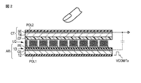
図2は、図1に示すセンサ付き表示デバイス10の一構成例を概略的に示す断面図である。なお、図2における第1方向Xと第2方向Yとは互いに略直交する方向であり、第3方向Zは、第1方向Xと第2方向Yとにより規定される平面と略直交する方向である。
FIG. 2 is a cross-sectional view schematically showing a configuration example of the sensor-equipped
センサ付き表示デバイス10は、表示デバイスとして液晶表示デバイスを用いると共に、この液晶表示デバイスに元々備えられている電極の一部(後述する共通電極CE)および表示用駆動信号(後述するコモン駆動信号VCOM)を兼用して静電容量型センサを構成したものである。
The sensor-equipped
センサ付き表示デバイス10は、アレイ基板ARと、対向基板CTと、アレイ基板ARと対向基板CTとの間に保持された液晶層LQと、を備えている。
The sensor-equipped
アレイ基板ARは、第1偏光板POL1と、TFT基板12と、共通電極CEと、画素電極PEと、を備えている。
The array substrate AR includes a first polarizing plate POL1, a
TFT基板12は、ガラス等の透明絶縁基板と、図示しないスイッチング素子と、ソース配線やゲート配線等の各種配線と、これらを覆う絶縁膜である平坦化層と、を備えている。スイッチング素子は、例えば第1方向Xを行方向とし第2方向Yを列方向としたマトリクス状に配置され、ゲート配線に供給される信号によりソース配線と画素電極PEとの接続を切り替える。
The
共通電極CEは、TFT基板12上に配置され絶縁層13に覆われている。共通電極CEは、例えば、第1方向Xに延びるとともに第2方向Yに複数並んで配置されている。共通電極CEは、例えばITO(Indium Tin Oxide)やIZO(Indium zinc oxide)等の透明電極材料によって形成されている。本実施形態では、共通電極CEは、センサ用駆動電極としても用いられる。
The common electrode CE is disposed on the
画素電極PEは、絶縁層13上に配置され図示しない配向膜に覆われている。画素電極PEは、例えば第1方向Xを行方向とし第2方向Yを列方向としたマトリクス状に並んで配置されている。複数行の画素電極PEが絶縁層13を介して1つの共通電極CEと対向している。画素電極PEは、例えばITOやIZO等の透明電極材料によって形成されている。
The pixel electrode PE is disposed on the
第1偏光板POL1は、TFT基板12の外側(共通電極CEと反対側)の主面に配置されている。 The first polarizing plate POL1 is disposed on the main surface outside the TFT substrate 12 (on the side opposite to the common electrode CE).
対向基板CTは、ガラス等の透明絶縁基板14と、カラーフィルタCFと、検出電極SEと、第2偏光板POL2と、を備えている。
The counter substrate CT includes a
カラーフィルタCFは、透明絶縁基板14上に格子状に配置されたブラックマトリクス(図示せず)を覆うように配置されている。カラーフィルタCFは、例えば複数の着色層を備え、第1方向Xに隣接する画素にそれぞれ配置されたカラーフィルタCFの着色層は、互いに色が異なっている。例えば、カラーフィルタCFは、赤色、青色、緑色といった3原色にそれぞれ着色された樹脂材料によって形成された着色層を備えている。赤色に着色された樹脂材料からなる赤色着色層(図示せず)は、赤色画素に対応して配置されている。青色に着色された樹脂材料からなる青色着色層(図示せず)は、青色画素に対応して配置されている。緑色に着色された樹脂材料からなる緑色着色層は、緑色画素に対応して配置されている。これらの着色層同士の境界は、ブラックマトリクスと重なる位置にある。カラーフィルタCFは、オーバーコート層(図示せず)に覆われている。オーバーコート層は、カラーフィルタCFの表面の凹凸の影響を緩和する。オーバーコート層は、図示しない配向膜に覆われている。
The color filter CF is arranged so as to cover a black matrix (not shown) arranged in a lattice pattern on the transparent
検出電極SEは、透明絶縁基板14の外側(カラーフィルタCFと反対側)の主面に配置されている。検出電極SEは、共通電極CEが延びた方向(第1方向X)と略直交する方向(第2方向Y)に延びるとともに、第1方向Xに複数並んで配置されている。検出電極SEは、例えばITOやIZO等の透明電極材料によって形成されている。
The detection electrode SE is disposed on the main surface on the outer side (opposite side to the color filter CF) of the transparent insulating
第2偏光板POL2は、検出電極SE上(透明絶縁基板14のカラーフィルタCFと反対側)に配置されている。第1偏光板POL1の第1偏光軸と、第2偏光板POL2の第2偏光軸とは、例えば、直交する位置関係(クロスニコル)にある。このとき、一方の偏光板は、例えば、その偏光軸が液晶分子の初期配向方向と平行または直交するように配置されている。
The second polarizing plate POL2 is disposed on the detection electrode SE (on the opposite side of the transparent insulating
図3は、図2に示すセンサ付き表示デバイスの共通電極CEと検出電極SEとの一構成例を説明するための斜視図である。 FIG. 3 is a perspective view for explaining one configuration example of the common electrode CE and the detection electrode SE of the sensor-equipped display device shown in FIG.
この例では、共通電極CEは、第2方向Y(図の左右方向)に延在する複数のストライプ状の電極パタンに分割されている。映像信号書込み時に、電極パタンには、ドライバによって共通電圧VCOMが順次印加(供給)され、時分割的に線順次走査駆動が行われる。また、センサ駆動時に、各電極パタン(または、複数の電極パタンを組とした各電極パタン群)には、ディスプレイドライバ回路30によってセンサ駆動信号Txが順次印加される。本実施形態では、各電極パタン(または、複数の電極パタンを組とした各電極パタン群)に順次印加されるセンサ駆動信号Txをセンサ駆動信号Tx1〜Txnと称す。Txの添え字「n」は、各電極パタンにセンサ駆動信号Txが順次印加される場合には電極パタンの数を表し、複数の電極パタンを組とした各電極パタン群にセンサ駆動信号Txが順次印加される場合には電極パタン群の数を表す。
In this example, the common electrode CE is divided into a plurality of stripe-shaped electrode patterns extending in the second direction Y (left-right direction in the figure). At the time of writing a video signal, a common voltage VCOM is sequentially applied (supplied) to the electrode pattern by a driver, and line-sequential scanning driving is performed in a time division manner. Further, when the sensor is driven, the
一方、検出電極SEは、共通電極CEの電極パタンの延在方向と直交する方向に延びる複数(m)のストライプ状の電極パタン1〜電極パタンmから構成されている。検出電極SEの各電極パタンそれぞれからは、センサ検出値Rxが出力され、図1に示した検出回路20へ入力される。本実施形態では、特に、電極パタン1〜電極パタンmそれぞれから出力されるセンサ検出値Rxを、センサ検出値Rx1〜Rxmと称す。
On the other hand, the detection electrode SE is composed of a plurality (m) of
図4は、静電容量型センサの駆動信号と検出信号との一例を示す図である。静電容量型センサは、誘電体を挟んで互いに対向配置された一対の電極(共通電極CEおよび検出電極SE)を備え、第1容量素子を構成する。 FIG. 4 is a diagram illustrating an example of a drive signal and a detection signal of the capacitive sensor. The capacitance type sensor includes a pair of electrodes (a common electrode CE and a detection electrode SE) disposed to face each other with a dielectric interposed therebetween, and constitutes a first capacitance element.
第1容量素子は、その一端が交流信号源に接続され、他端は抵抗を介して接地されると共に図1に示す検出回路20に接続される。交流信号源から共通電極CE(容量素子の一端)に所定の周波数(例えば数kHz〜十数kHz程度)の交流矩形波(センサ駆動信号Tx)を印加すると、検出電極SE(第1容量素子の他端)に、図4に示したような出力波形(センサ検出値Rx)が現れる。
One end of the first capacitive element is connected to an AC signal source, and the other end is grounded via a resistor and connected to the
指を接触していない状態では、第1容量素子に対する充放電に伴って、第1容量素子の容量値に応じた電流が流れる。このときの第1容量素子の他端の電位波形は、例えば図4の波形V0のようになり、これが検出回路20によって検出される。
In a state where the finger is not touched, a current corresponding to the capacitance value of the first capacitor element flows along with charge / discharge of the first capacitor element. The potential waveform at the other end of the first capacitive element at this time is, for example, a waveform V0 in FIG. 4, which is detected by the
一方、指を接触した状態では、指によって形成される第2容量素子が第1容量素子に直列に追加された形となる。この状態では、第1容量素子と第2容量素子とに対する充放電に伴って、それぞれ電流が流れる。このときの第1容量素子の他端の電位波形は、例えば図4の波形V1のようになり、これが検出回路20によって検出される。このとき、第1容量素子の他端の電位は、第1容量素子と第2容量素子とを流れる電流の値によって定まる分圧電位となる。このため、波形V1は、非接触状態での波形V0よりも小さい値となる。したがって、このセンサ検出値Rxと閾値Vthと比較することにより、センサに接触しているか否かを判断することが可能となる。
On the other hand, when the finger is in contact, the second capacitive element formed by the finger is added in series to the first capacitive element. In this state, current flows through charging and discharging of the first capacitor element and the second capacitor element, respectively. The potential waveform at the other end of the first capacitive element at this time is, for example, a waveform V1 in FIG. 4 and is detected by the
なお、上記説明ではセンサに接触しているか否かを検出する方法について説明したが、センサに接触していない状態でもセンサ検出値Rxは変化するものであるので、ホバリング検出等も可能である。 In the above description, the method for detecting whether or not the sensor is touched has been described. However, since the sensor detection value Rx changes even when the sensor is not touched, hovering detection or the like is possible.
本実施形態では、ローデータとは、共通電極CEの電極パタン(あるいは電極パタン群)と検出電極SEの電極パタンとが交差する位置座標とその位置におけるセンサ検出値Rxの物理量(電極間容量値あるいは検出電極電圧値)とが対応付けられた情報を有する3次元情報である。 In the present embodiment, raw data refers to the position coordinates at which the electrode pattern (or electrode pattern group) of the common electrode CE and the electrode pattern of the detection electrode SE intersect, and the physical quantity (interelectrode capacitance value) of the sensor detection value Rx at that position. Alternatively, it is three-dimensional information having information associated with the detection electrode voltage value).
検出電極SEからは、センサ駆動信号Tx1が印加されたタイミングで得られるm個のセンサ検出値Rx1〜Rxmで構成されるローデータ(ローデータTx♯1と称す)が出力される。同様に、検出電極SEからは、センサ駆動信号Tx2が印加されたタイミングで得られるm個のセンサ検出値Rx1〜Rxmで構成されるローデータ(ローデータTx♯2と称す)が出力される。以降同様に、検出電極SEからは、1検出期間(1フレーム期間)において、センサ駆動信号Txnが印加されたタイミングで得られるm個のセンサ検出値Rx1〜Rxmで構成されるローデータ(ローデータTx♯nと称す)が出力される。本実施形態では、ローデータTx♯1〜Tx♯nを合わせたローデータを特にローデータ群と称す。
From the detection electrode SE, raw data (referred to as raw data Tx # 1) composed of m sensor detection values Rx1 to Rxm obtained at the timing when the sensor drive signal Tx1 is applied is output. Similarly, the detection electrode SE outputs raw data (referred to as raw data Tx # 2) composed of m sensor detection values Rx1 to Rxm obtained at the timing when the sensor drive signal Tx2 is applied. Similarly, from the detection electrode SE, in one detection period (one frame period), raw data (low data) composed of m sensor detection values Rx1 to Rxm obtained at the timing when the sensor drive signal Txn is applied. Is referred to as Tx # n). In the present embodiment, the raw data combining the raw
図5は、図1に示す電子機器の検出回路20およびディスプレイドライバ回路30の一構成例を概略的に示すブロック図である。
FIG. 5 is a block diagram schematically showing a configuration example of the
ディスプレイドライバ回路30は、複数のテーブル(Table1、Table2、…)から1つのテーブルを選択するテーブル選択部TBを備えている。各テーブルには、センサの検出期間(センサ水平期間TSHDがHレベルとなる期間)、センサ駆動信号Txのパルス幅および、センサの駆動方法などの値が格納されている。ディスプレイドライバ回路30は、複数のテーブルのうちの1つを選択して格納された情報を用いて、映像表示信号Sigxおよびセンサ駆動信号Txのタイミングを制御する。例えば、センサによりホバリング動作を検出するときと、表示デバイスへの接触を検出するときとでは、センサ駆動信号Txのパルス幅を変更した方が望ましい。
The
検出回路20は、センサ処理部22、同期処理部24と、テーブルコントローラ26と、センサ駆動タイミングコントローラ28と、データセット処理部DSと、を備えている。
The
センサ処理部22は、比較器COMPと、A/D変換器222と、フィルタ224と、タイミングコントローラTCONとを備えている。
The
比較器COMPは、センサ付き表示デバイス10からセンサ検出値Rxを受信し、閾値Refとの差分を出力する。比較器COMPはその前段に配置されたスイッチSW1によりセンサ付き表示デバイス10との接続が切り替えられる。比較器COMPには、コンデンサとスイッチSW2とが並列に接続されている。比較器COMPの出力はスイッチSW2を切り替えることによりリセットされる。スイッチSW1およびスイッチSW2の切り替えはタイミングコントローラTCONにより制御される。
The comparator COMP receives the sensor detection value Rx from the sensor-equipped
A/D変換器222は、比較器COMPから出力された値を所定のタイミングでサンプリングするとともに所定期間保持して、デジタル信号としてフィルタ222へ出力する。フィルタ224は、例えばFIRフィルタ等のデジタルフィルタを含む。フィルタ224の演算では、アプリケーションプロセッサ40から送信されたセンサ設定信号(TP setting)に含まれている係数(FIR coefficient)を用いる。フィルタ224は、演算処理後の値をローデータとしてデータセット処理部DSへ出力する。すなわち、ローデータは、センサ検出値Rxと閾値Refとの差分値からノイズ成分を除去したデジタルデータである。
The A /
テーブルコントローラ26は、アプリケーションプロセッサ40から受信したテーブル選択信号(Table Sel.)に基づいて、テーブル選択要求TRCRQを生成し、ディスプレイドライバへ出力する。テーブル選択信号(Table Sel.)は、アプリケーションプロセッサ40から検出回路20へシリアル通信の規格、例えばSPIやI2C通信規格に基づく構造で送信される。テーブルコントローラ26は、受信したテーブル選択信号(Table Sel.)をパラレル信号に変換して出力する。
The
センサ駆動タイミングコントローラ28は、アプリケーションプロセッサ40からセンサ設定信号(TP setting)を受信する。センサ設定信号(TP setting)は、アプリケーションプロセッサ40から検出回路20へシリアル通信の規格、例えばSPIやI2C通信規格に基づく構造で送信される。センサ駆動タイミングコントローラ28は、センサ設定信号(TP setting)に含まれるセンサ駆動信号Txの周波数、センサ駆動信号Txのパルス数を用いてセンサ駆動タイミング信号EXVCOMを生成し、ディスプレイドライバ回路30へ出力する。
The sensor
なお、センサ駆動信号Txのパルス数および周波数は、ディスプレイドライバ回路30のテーブル毎に格納されたセンサの検出期間(水平期間TSHDがHレベルとなる期間)全体を使用するように変更されることが望ましい。そのため、アプリケーションプロセッサ40は、使用するテーブルに応じてセンサ設定信号(TP setting)に含まれるセンサ駆動信号Txの周波数、センサ駆動信号Txのパルス数の値を変更することが望ましい。
The number of pulses and the frequency of the sensor drive signal Tx may be changed to use the entire sensor detection period (period in which the horizontal period TSHD is at the H level) stored for each table of the
同期処理部24は、ディスプレイドライバ回路30からセンサ水平期間TSHDおよびセンサ垂直期間TSVDを受信し、何番目の電極パタン(あるいは電極パタン群)が駆動されたか、および、フレーム期間を区別して、電極パタンおよびフレーム期間に応じて予め設定された記号や番号等の識別値をデータセット処理部DSへ出力する。
The
データセット処理部DSは、センサ処理部22から受信したローデータと、アプリケーションプロセッサ40から受信したセンサ設定信号(TP setting)、ディスプレイドライバ回路30から受信したテーブル設定TSCSTに基づくディスプレイドライバ回路30による制御に関する情報、同期処理部24及びデータセット処理部22から得られる検出回路20による制御に関する情報を合わせてデータセットDataを生成する。データセットDataに含まれる情報については、後述する。データセット処理部DSは、アプリケーションプロセッサ40へ出力する。なお、データセット処理部DSは、データセットDataを例えばSPIやI2C等のシリアル通信規格に基づく構造で送信する。データセット処理部DSは、データセットDataをアプリケーションプロセッサ40へ出力する際に先立って、割り込み要求信号IRQをアプリケーションプロセッサ40へ出力する。
The data set processing unit DS is controlled by the
図6は、データセット処理部DSが生成するデータセットDataに含まれる内容の一例を示す図である。データセットDataは、これに含まれるローデータTxに応じて、異なるデータを含む。ローデータTx♯1を含むデータセットDataは、ローデータ、DDI状態、Touch IC状態、スタートフラグ、フレームインデックスを含む。フレームインデックスは、任意であってもよい。ローデータは、ローデータTx♯1である。DDI状態は、タッチ時間、タッチレポートレート(表示の分割数)、センサ駆動信号Txの電圧、センサ駆動信号Txのパルス幅等を含むディスプレイドライバ回路30による制御に関する情報である。Touch IC状態は、センサ駆動信号Txの周波数、センサ駆動信号Txパルス数、これらのパラメータに伴う検出部定数を含む検出回路20による制御に関する情報である。スタートフラグは、1検出期間中で最初(1ライン目)に印加されたセンサ駆動信号Tx1に応じたローデータTx♯1であることを示すフラグである。フレームインデックスは、データセットDataの欠損対策のデータである。なお、データセットDataは、少なくともローデータとスタートフラグが含まれていればよく、DDI状態、Touch IC状態、フレームインデックスが含まれていなくてもよい。
FIG. 6 is a diagram illustrating an example of contents included in the data set Data generated by the data set processing unit DS. The data set Data includes different data according to the raw data Tx included therein. The data set Data including the raw
ローデータTx♯2〜Tx♯nの何れか1つを含むデータセットDataは、ローデータ(ローデータTx♯2〜Tx♯nの何れか1つ)、DDI状態、Touch IC状態、Txナンバー(Tx number)、フレームインデックスを含む。DDI状態、Touch IC状態、Txナンバー、フレームインデックスは、任意であってもよい。なお、データセットDataは、少なくともローデータが含まれていればよく、DDI状態、Touch IC状態、Txナンバー、フレームインデックスが含まれていなくてもよい。Txナンバーは、1検出期間中で何番目(何ライン目)に印加されたセンサ駆動信号Txに応じたローデータであるのかを示すフラグである。Txナンバーは、データの抜け防止のためのフラグである。
A data set Data including any one of the row
図7は、検出回路20がアプリケーションプロセッサ40へH-Sync Modeで出力するデータセットDataの出力タイミングについて説明する図である。データセット処理部DSは、検出電極SEから1検出期間中の最初のローデータTx♯1を受けると、割り込み要求信号IRQをアプリケーションプロセッサ40へ出力する。アプリケーションプロセッサ40は、割り込み要求信号IRQに応答して、データセット処理部DSからデータセットDataを読み出そうとする。データセット処理部DSは、図6に示すローデータTx1を含むデータセットDataをアプリケーションプロセッサ40へ出力する。つまり、データセット処理部DSは、ローデータTx1(1検出期間中の最初の検出データ)をスタートフラグと共にアプリケーションプロセッサ40へ出力する。なお、データセット処理部DSは、共通電極CEに駆動電圧Tx2が印加されている間(つまり、ローデータTx2が得られようとしている間)に、ローデータTx1を含むデータセットDataをアプリケーションプロセッサ40へ出力することになる。
FIG. 7 is a diagram for explaining the output timing of the data set Data that the
データセット処理部DSからアプリケーションプロセッサ40へのデータセットDataの転送時間は、例えば、0.03ms以内である。データセットDataのデータサイズは、例えば、Txライン数×16bitである。Rxライン数は、検出電極SEの電極パタン数mに対応する。
The transfer time of the data set Data from the data set processing unit DS to the
同様に、データセット処理部DSは、検出電極SEからローデータTx♯2を受けると、割り込み要求信号IRQをアプリケーションプロセッサ40へ出力する。アプリケーションプロセッサ40は、割り込み要求信号IRQに応答して、検出回路20からデータセットDataを読み出そうとする。データセット処理部DSは、図6に示すローデータTx♯2を含むデータセットDataをアプリケーションプロセッサ40へ出力する。なお、データセット処理部DSがアプリケーションプロセッサ40へIRQを送信する間隔、つまり、データセット処理部DSがアプリケーションプロセッサ40へデータセットDataを送信する間隔(1Tx期間)は、例えば、0.1ms以上である。
Similarly, upon receiving raw
同様に、データセット処理部DSは、検出電極SEから1検出期間中の最後のローデータTx♯nを受けると、割り込み要求信号IRQをアプリケーションプロセッサ40へ出力する。アプリケーションプロセッサ40は、割り込み要求信号IRQに応答して、データセット処理部DSからデータセットDataを読み出そうとする。データセット処理部DSは、図6に示すローデータTx♯nを含むデータセットDataをアプリケーションプロセッサ40へ出力する。データセット処理部DSは、センサ駆動信号Tx単位で、つまり、ローデータTx♯1〜Tx♯nが得られる毎に、順次アプリケーションプロセッサ40へ出力する。つまり、検出回路20は、共通電極CEにセンサ駆動信号Txが印加されるタイミング毎に検出電極SEの電極パタンから得られる物理量データを含む検出データ(ローデータTx♯1〜Tx♯n)をアプリケーションプロセッサ40へ出力する。
Similarly, when receiving the last row data Tx # n during one detection period from the detection electrode SE, the data set processing unit DS outputs an interrupt request signal IRQ to the
データセット処理部DSは、次の1検出期間のローデータTx♯1〜Tx♯nについても上記同様、異なるローデータを含むデータセットDataを順次アプリケーションプロセッサ40へ出力する。なお、データセット処理部DSがアプリケーションプロセッサ40へ1検出期間中のローデータを全て送信する間隔(ローデータTx1を含むデータセットDataの出力開始時からローデータTxnを含むデータセットDataの出力開始時までの間隔)は、例えば、8.4msである。
Similarly to the above, the data set processing unit DS sequentially outputs data sets Data including different row data to the
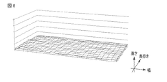
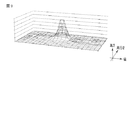
アプリケーションプロセッサ40は、1検出期間中のローデータTx♯1〜Tx♯nを順次メモリに保持する。アプリケーションプロセッサ40は、1検出期間中のローデータTx♯1〜Tx♯nが揃った後に、ローデータTx♯1〜Tx♯nを含むローデータ群を用いて、演算処理(3次元データ処理)を実行する。図8および図9は、ローデータ群に基づく3次元データの一例を示す図である。図8では、ユーザの指等がセンサの近傍にないときのローデータ群に基づく3次元データの一例を示している。図9では、ユーザの指等がセンサの近にあるときのローデータ群に基づく3次元データの一例を示している。なお、図8および図9では、幅方向(センサ駆動信号Txによるスキャン方向)および奥行方向に位置座標、高さ方向に物理量をとってローデータ群をプロットしている。
The
アプリケーションプロセッサ40は、演算処理により得られた3次元データを用いて各種アプリケーションによる処理(App. layer)を実行する。
The
なお、アプリケーションプロセッサ40は1検出期間中のローデータTx♯1〜Tx♯nのうち少なくとも1つのローデータに欠陥があった場合に、1検出期間中の全てのローデータ(ローデータTx♯1〜Tx♯n)を利用しないようにしてもよい。これは、アプリケーションプロセッサ40がローデータの欠如によって誤検出することを防止するためである。
Note that if at least one of the row
本実施形態によれば、検出回路20のアプリケーションプロセッサ40へのデータ転送を効率化し、待ち時間(latency)を改善する。また、本実施形態によれば、検出回路20は、簡易な構成でローデータTx♯1〜Tx♯nの何れか1つを含むデータセットDataを順次アプリケーションプロセッサ40へ出力できる。検出回路20は、ローデータTx♯1〜Tx♯nを順次メモリに保持する必要がないため、メモリの容量を大きくする必要がない。さらに、検出回路20が1検出期間中の最後にアプリケーションプロセッサ40へ出力するデータセットDataが含むローデータは、ローデータTx♯nのみである。そのため、アプリケーションプロセッサ40は、ローデータTx♯nを受信したらすぐにローデータ群を用いた演算処理を開始できる。つまり、検出回路20が1検出期間中の最後のデータセットDataの送信を開始した時からアプリケーションプロセッサ40がローデータ群を用いた演算処理を開始するまでの時間は、ローデータTx♯1〜ローデータTx♯n全てが1つのデータセットDataで送信される場合と比べて、短くなる。結果として、アプリケーションプロセッサ40は、表示画面の更新を早くできる。さらに、アプリケーションプロセッサ40は、センサにより検出された座標ではなく、座標位置と物理量とを含む3次元情報を含むローデータ群を用いて演算処理を実行し、3次元データを用いて各種アプリケーションを実行できる。そのため、電子機器の高性能化が期待できる。本実施形態は、センサが高精細化したとしても、検出回路20に特別な構成上の変更を必要とすることなく、適用できる。以上より、汎用性の高い電子機器および電子機器の制御方法を提供するができる。
According to this embodiment, the data transfer to the
本発明のいくつかの実施形態を説明したが、これらの実施形態は、例として提示したものであり、発明の範囲を限定することは意図していない。これら新規な実施形態は、その他の様々な形態で実施されることが可能であり、発明の要旨を逸脱しない範囲で、種々の省略、置き換え、変更を行うことができる。これら実施形態やその変形は、発明の範囲や要旨に含まれるとともに、特許請求の範囲に記載された発明とその均等の範囲に含まれる。 Although several embodiments of the present invention have been described, these embodiments are presented by way of example and are not intended to limit the scope of the invention. These novel embodiments can be implemented in various other forms, and various omissions, replacements, and changes can be made without departing from the scope of the invention. These embodiments and modifications thereof are included in the scope and gist of the invention, and are included in the invention described in the claims and the equivalents thereof.
なお、本実施形態では、アプリケーションプロセッサ40の構成はハードウェアで実現されてもよく、ソフトウェアで実現されてもよい。
In the present embodiment, the configuration of the
なお、上記の説明では、センサ付き表示デバイスが表示デバイスとして液晶表示デバイスを備えた構成について説明したが、有機エレクトロルミネッセンス表示デバイスなど他の表示デバイスを備えた構成であっても良い。また、図2などに示した例では、液晶表示デバイスは、画素電極PE及び共通電極CEの双方がアレイ基板ARに備えられた構成、すなわち、IPS(In−Plane Switching)モードやFFS(Fringe Field Switching)モードなどの主として横電界(フリンジ電界も含む)を利用する構成について説明したが、液晶表示デバイスの構成はこれらに限らない。少なくとも画素電極PEはアレイ基板ARに備えられ、共通電極CEはアレイ基板AR及び対向基板CTのいずれに備えられていても良い。TN(Twisted Nematic)モード、OCB(Optically Compensated Bend)モード、VA(Vertical Aligned)モードなどの主として縦電界を利用する構成の場合、共通電極CEは対向基板CTに備えられる。つまり、共通電極CEが配置される位置は、TFT基板12を構成する絶縁基板と対向基板CTを構成する絶縁基板14との間であれば良い。
In the above description, the sensor-equipped display device has been described as including a liquid crystal display device as a display device. However, a configuration including another display device such as an organic electroluminescence display device may be used. In the example shown in FIG. 2 and the like, the liquid crystal display device has a configuration in which both the pixel electrode PE and the common electrode CE are provided on the array substrate AR, that is, an IPS (In-Plane Switching) mode or an FFS (Fringe Field). Although a configuration using mainly a horizontal electric field (including a fringe electric field) such as a switching mode has been described, the configuration of the liquid crystal display device is not limited thereto. At least the pixel electrode PE may be provided on the array substrate AR, and the common electrode CE may be provided on either the array substrate AR or the counter substrate CT. In the case of a configuration that mainly uses a vertical electric field, such as a TN (Twisted Nematic) mode, an OCB (Optically Compensated Bend) mode, or a VA (Vertical Aligned) mode, the common electrode CE is provided in the counter substrate CT. That is, the position where the common electrode CE is disposed may be between the insulating substrate constituting the
X…第1方向、Y…第2方向、VCOM…共通電圧、Tx…センサ駆動信号、Rx…センサ検出値、Data…データセット、TPsetting…センサ設定信号、TSVD…センサ垂直期間、TSHD…センサ水平期間、TRCRQ…テーブル選択要求、TSCST…テーブル設定、10…センサ付き表示デバイス、AR…アレイ基板、CT…対向基板、12…TFT基板、13…絶縁層、14…透明絶縁基板、POL1、POL2…偏光板、LQ…液晶層、CE…共通電極(第2電極)、PE…画素電極(第1電極)、CF…カラーフィルタ、SE…検出電極(第3電極)、20…検出回路、22…センサ処理部、TCON…タイミングコントローラ、COMP…比較器、Ref…閾値、SW1…スイッチ(直列スイッチ)、SW2…スイッチ(リセットスイッチ)、222…A/D変換器、224…フィルタ、24…同期処理部、26…テーブルコントローラ、28…センサ駆動タイミングコントローラ、DS…データセット処理部、30…ディスプレイドライバ回路、TB…テーブル選択部、40…アプリケーションプロセッサ。 X ... first direction, Y ... second direction, VCOM ... common voltage, Tx ... sensor drive signal, Rx ... sensor detection value, Data ... data set, TPsetting ... sensor setting signal, TSVD ... sensor vertical period, TSHD ... sensor horizontal Period, TRCRQ ... Table selection request, TSCST ... Table setting, 10 ... Display device with sensor, AR ... Array substrate, CT ... Counter substrate, 12 ... TFT substrate, 13 ... Insulating layer, 14 ... Transparent insulating substrate, POL1, POL2 ... Polarizing plate, LQ ... liquid crystal layer, CE ... common electrode (second electrode), PE ... pixel electrode (first electrode), CF ... color filter, SE ... detection electrode (third electrode), 20 ... detection circuit, 22 ... Sensor processing unit, TCON ... timing controller, COMP ... comparator, Ref ... threshold, SW1 ... switch (series switch), SW2 ... switch ( Reset switch), 222 ... A / D converter, 224 ... filter, 24 ... synchronization processing unit, 26 ... table controller, 28 ... sensor drive timing controller, DS ... data set processing unit, 30 ... display driver circuit, TB ... table Selection unit, 40... Application processor.
Claims (6)
前記第2電極の前記電極パタンに、順次センサ駆動信号を印加するディスプレイドライバ回路と、
前記第2電極の前記電極パタンに前記センサ駆動信号が印加されるタイミング毎に前記第3電極の複数の電極パタンから得られる物理量データを含む検出データを順次出力する検出回路と、
前記検出回路から受信した前記検出データを処理するアプリケーションプロセッサと、を有し、
前記検出回路は、前記第3電極の複数の電極パタンから前記物理量データを検出する毎に、前記アプリケーションプロセッサに割り込み要求信号を出力し、前記アプリケーションプロセッサからの応答に対応して前記検出データを前記アプリケーションプロセッサに出力する電子機器。 A plurality of first electrodes arranged in a matrix and a plurality of first electrodes arranged opposite to the first electrodes, extending along the first direction and arranged side by side in a second direction intersecting the first direction A second electrode including an electrode pattern; a third electrode including a plurality of electrode patterns disposed to face the second electrode, extending along the second direction and arranged side by side in the first direction; A display device comprising:
A display driver circuit that sequentially applies a sensor drive signal to the electrode pattern of the second electrode;
A detection circuit that sequentially outputs detection data including physical quantity data obtained from a plurality of electrode patterns of the third electrode at each timing when the sensor drive signal is applied to the electrode pattern of the second electrode;
An application processor for processing the detection data received from the detection circuit ;
The detection circuit outputs an interrupt request signal to the application processor each time the physical quantity data is detected from a plurality of electrode patterns of the third electrode, and the detection data is output in response to a response from the application processor. Electronic equipment that outputs to the application processor .
前記第2電極の前記電極パタンに、順次センサ駆動信号を印加するディスプレイドライバ回路と、
前記第2電極の前記電極パタンに前記センサ駆動信号が印加されるタイミングで前記第3電極の複数の電極パタンから物理量データを検出する検出回路を備える電子機器の制御方法において、
前記第2電極の前記電極パタンに前記センサ駆動信号が印加されるタイミング毎に得られる前記物理量データを含む検出データを順次アプリケーションプロセッサへ送信し、
前記検出回路は、前記第3電極の複数の電極パタンから前記物理量データを検出する毎に、前記アプリケーションプロセッサに割り込み要求信号を出力し、前記アプリケーションプロセッサからの応答に対応して前記検出データを前記アプリケーションプロセッサに出力する、制御方法。 A plurality of first electrodes arranged in a matrix and a plurality of first electrodes arranged opposite to the first electrodes, extending along the first direction and arranged side by side in a second direction intersecting the first direction A second electrode including an electrode pattern; a third electrode including a plurality of electrode patterns disposed to face the second electrode, extending along the second direction and arranged side by side in the first direction; A display device comprising:
A display driver circuit that sequentially applies a sensor drive signal to the electrode pattern of the second electrode;
In a control method of an electronic device including a detection circuit that detects physical quantity data from a plurality of electrode patterns of the third electrode at a timing when the sensor driving signal is applied to the electrode pattern of the second electrode.
Sequentially transmitting detection data including the physical quantity data obtained at each timing when the sensor drive signal is applied to the electrode pattern of the second electrode to the application processor ;
The detection circuit outputs an interrupt request signal to the application processor each time the physical quantity data is detected from a plurality of electrode patterns of the third electrode, and the detection data is output in response to a response from the application processor. Control method to output to the application processor .
Priority Applications (5)
| Application Number | Priority Date | Filing Date | Title |
|---|---|---|---|
| JP2013073874A JP5865287B2 (en) | 2013-03-29 | 2013-03-29 | Electronic device and control method of electronic device |
| US14/182,432 US9746949B2 (en) | 2013-03-29 | 2014-02-18 | Electronic device for efficiently performing data transmission and method for controlling the same |
| TW103107077A TWI524246B (en) | 2013-03-29 | 2014-03-03 | Electronic device and method for controlling the same |
| KR1020140034457A KR101635260B1 (en) | 2013-03-29 | 2014-03-25 | Electronic device and method for controlling the same |
| CN201410119329.XA CN104076978B (en) | 2013-03-29 | 2014-03-27 | Electronic device and method for controlling the same |
Applications Claiming Priority (1)
| Application Number | Priority Date | Filing Date | Title |
|---|---|---|---|
| JP2013073874A JP5865287B2 (en) | 2013-03-29 | 2013-03-29 | Electronic device and control method of electronic device |
Related Child Applications (1)
| Application Number | Title | Priority Date | Filing Date |
|---|---|---|---|
| JP2015249879A Division JP6134775B2 (en) | 2015-12-22 | 2015-12-22 | Electronic device and control method of electronic device |
Publications (2)
| Publication Number | Publication Date |
|---|---|
| JP2014199497A JP2014199497A (en) | 2014-10-23 |
| JP5865287B2 true JP5865287B2 (en) | 2016-02-17 |
Family
ID=51598284
Family Applications (1)
| Application Number | Title | Priority Date | Filing Date |
|---|---|---|---|
| JP2013073874A Active JP5865287B2 (en) | 2013-03-29 | 2013-03-29 | Electronic device and control method of electronic device |
Country Status (5)
| Country | Link |
|---|---|
| US (1) | US9746949B2 (en) |
| JP (1) | JP5865287B2 (en) |
| KR (1) | KR101635260B1 (en) |
| CN (1) | CN104076978B (en) |
| TW (1) | TWI524246B (en) |
Families Citing this family (3)
| Publication number | Priority date | Publication date | Assignee | Title |
|---|---|---|---|---|
| SG11201703438YA (en) | 2014-11-18 | 2017-06-29 | Tactual Labs Co | System and method for timing input sensing, rendering, and display to minimize latency |
| TWI611322B (en) * | 2015-05-15 | 2018-01-11 | 瑞鼎科技股份有限公司 | In-cell touch panel |
| CN108900750B (en) * | 2018-07-19 | 2020-08-28 | 维沃移动通信有限公司 | Image sensor and mobile terminal |
Family Cites Families (36)
| Publication number | Priority date | Publication date | Assignee | Title |
|---|---|---|---|---|
| JPH11184630A (en) | 1997-12-22 | 1999-07-09 | Nec Corp | Liquid crystal display device provided with touch panel |
| US20060288185A1 (en) | 2005-06-17 | 2006-12-21 | Dell Products L.P. | System and method for implementing a common descriptor format |
| US8243027B2 (en) | 2006-06-09 | 2012-08-14 | Apple Inc. | Touch screen liquid crystal display |
| CN104484066B (en) * | 2006-06-09 | 2017-08-08 | 苹果公司 | Touch screen LCD |
| JP2008065730A (en) | 2006-09-11 | 2008-03-21 | Nec Corp | Portable communication terminal device, and coordinate input method and coordinate input device for portable communication terminal device |
| JP4816668B2 (en) | 2008-03-28 | 2011-11-16 | ソニー株式会社 | Display device with touch sensor |
| TWI356305B (en) | 2008-05-26 | 2012-01-11 | Via Tech Inc | Usb host controller and control method thereof |
| CN101661361A (en) * | 2008-08-27 | 2010-03-03 | 比亚迪股份有限公司 | Multipoint touch detection system |
| JP4683126B2 (en) * | 2008-12-26 | 2011-05-11 | ブラザー工業株式会社 | Input device |
| US8358285B2 (en) * | 2009-05-06 | 2013-01-22 | Silicon Laboratories Inc. | Method and apparatus for scanning a touchscreen with multi-touch detection using master/slave devices |
| JP5203291B2 (en) * | 2009-05-18 | 2013-06-05 | 株式会社ジャパンディスプレイウェスト | Display device and electronic device |
| JP2011002926A (en) * | 2009-06-17 | 2011-01-06 | Hitachi Ltd | Display device with tactile exhibition function |
| JP5513933B2 (en) * | 2009-06-30 | 2014-06-04 | 株式会社ジャパンディスプレイ | Touch sensor and display device |
| KR101442931B1 (en) * | 2009-09-02 | 2014-09-23 | 닛본 덴끼 가부시끼가이샤 | Display device |
| JP5278766B2 (en) * | 2009-09-07 | 2013-09-04 | Nltテクノロジー株式会社 | Touch position detection device, information input system, touch position detection method, touch position detection program |
| US8481873B2 (en) | 2009-09-30 | 2013-07-09 | Freescale Semiconductor, Inc. | Capacitive touch sensor device configuration systems and methods |
| TR201206796T1 (en) * | 2009-12-16 | 2013-01-21 | Sharp Kabushiki Kaisha | Coordinate sensor and display device. |
| JP2011170834A (en) | 2010-01-19 | 2011-09-01 | Sony Corp | Information processing apparatus, operation prediction method, and operation prediction program |
| JP2011175440A (en) * | 2010-02-24 | 2011-09-08 | Sony Corp | Apparatus and method for processing information and computer-readable recording medium |
| JP5429814B2 (en) | 2010-03-29 | 2014-02-26 | 株式会社ワコム | Indicator detection device and detection sensor |
| JP2011258143A (en) | 2010-06-11 | 2011-12-22 | Panasonic Corp | Touch panel device |
| JP5268118B2 (en) | 2010-08-20 | 2013-08-21 | 群創光電股▲ふん▼有限公司 | Touch panel, touch panel drive method, contact information acquisition program, and recording medium |
| US8963852B2 (en) | 2010-08-20 | 2015-02-24 | Innolux Corporation | Touch panel, driving method for the touch panel, program for getting touch information, and memory media |
| JP5722573B2 (en) * | 2010-08-24 | 2015-05-20 | 株式会社ジャパンディスプレイ | Display device with touch detection function |
| JP5198595B2 (en) | 2010-09-23 | 2013-05-15 | 奇美電子股▲ふん▼有限公司 | Input detection apparatus, input detection method, input detection program, and recording medium |
| JP5710449B2 (en) | 2011-04-13 | 2015-04-30 | 株式会社ジャパンディスプレイ | Display device, driving circuit, driving method, and electronic apparatus |
| KR101804316B1 (en) | 2011-04-13 | 2017-12-05 | 삼성디스플레이 주식회사 | Liquid crystal display |
| JP5659073B2 (en) | 2011-04-22 | 2015-01-28 | 株式会社ジャパンディスプレイ | Display panel with touch detector and electronic device |
| JP5823729B2 (en) | 2011-05-09 | 2015-11-25 | シナプティクス・ディスプレイ・デバイス合同会社 | Semiconductor device and data processing system |
| JP2012238210A (en) | 2011-05-12 | 2012-12-06 | Tokai Rika Co Ltd | Input device |
| JP2012252627A (en) * | 2011-06-06 | 2012-12-20 | Namco Bandai Games Inc | Program, information storage medium, and image generation system |
| JP2013003639A (en) | 2011-06-13 | 2013-01-07 | Tokai Rika Co Ltd | Electrostatic input device |
| KR101330809B1 (en) * | 2011-08-03 | 2013-12-19 | 주식회사 팬택 | Touch panel and electronic device including the touch panel |
| US9389716B2 (en) * | 2011-09-23 | 2016-07-12 | Sony Corporation | Mobile terminal apparatus |
| US8928609B2 (en) * | 2012-07-09 | 2015-01-06 | Stmicroelectronics International N.V. | Combining touch screen and other sensing detections for user interface control |
| JP5953258B2 (en) * | 2013-03-29 | 2016-07-20 | 株式会社ジャパンディスプレイ | Electronic device and control method of electronic device |
-
2013
- 2013-03-29 JP JP2013073874A patent/JP5865287B2/en active Active
-
2014
- 2014-02-18 US US14/182,432 patent/US9746949B2/en active Active
- 2014-03-03 TW TW103107077A patent/TWI524246B/en active
- 2014-03-25 KR KR1020140034457A patent/KR101635260B1/en active IP Right Grant
- 2014-03-27 CN CN201410119329.XA patent/CN104076978B/en active Active
Also Published As
| Publication number | Publication date |
|---|---|
| CN104076978B (en) | 2017-05-03 |
| KR20140118825A (en) | 2014-10-08 |
| US20140292677A1 (en) | 2014-10-02 |
| KR101635260B1 (en) | 2016-06-30 |
| TWI524246B (en) | 2016-03-01 |
| JP2014199497A (en) | 2014-10-23 |
| US9746949B2 (en) | 2017-08-29 |
| CN104076978A (en) | 2014-10-01 |
| TW201441905A (en) | 2014-11-01 |
Similar Documents
| Publication | Publication Date | Title |
|---|---|---|
| JP5845204B2 (en) | Electronic device and control method of electronic device | |
| US10345966B2 (en) | Touch integrated circuit using time-division and touch screen display device including the same | |
| JP5810121B2 (en) | Electronic device and control method of electronic device | |
| CN104423757A (en) | Touch integrated circuit and display device integrated with touch screen using the same | |
| US9823776B2 (en) | Electronic apparatus and method of controlling the same | |
| JP5865287B2 (en) | Electronic device and control method of electronic device | |
| JP5953258B2 (en) | Electronic device and control method of electronic device | |
| JP6082799B2 (en) | Electronic device, detection circuit control method, and detection circuit | |
| JP6055901B2 (en) | Electronics | |
| JP6134775B2 (en) | Electronic device and control method of electronic device | |
| JP6145485B2 (en) | Electronics | |
| US10627945B2 (en) | Touchscreen, method for touch detection, and wearable device |
Legal Events
| Date | Code | Title | Description |
|---|---|---|---|
| A621 | Written request for application examination |
Free format text: JAPANESE INTERMEDIATE CODE: A621 Effective date: 20150316 |
|
| A977 | Report on retrieval |
Free format text: JAPANESE INTERMEDIATE CODE: A971007 Effective date: 20150714 |
|
| A131 | Notification of reasons for refusal |
Free format text: JAPANESE INTERMEDIATE CODE: A131 Effective date: 20150721 |
|
| A521 | Request for written amendment filed |
Free format text: JAPANESE INTERMEDIATE CODE: A523 Effective date: 20150909 |
|
| TRDD | Decision of grant or rejection written | ||
| A01 | Written decision to grant a patent or to grant a registration (utility model) |
Free format text: JAPANESE INTERMEDIATE CODE: A01 Effective date: 20151201 |
|
| A61 | First payment of annual fees (during grant procedure) |
Free format text: JAPANESE INTERMEDIATE CODE: A61 Effective date: 20151225 |
|
| R150 | Certificate of patent or registration of utility model |
Ref document number: 5865287 Country of ref document: JP Free format text: JAPANESE INTERMEDIATE CODE: R150 |
|
| R250 | Receipt of annual fees |
Free format text: JAPANESE INTERMEDIATE CODE: R250 |
|
| R250 | Receipt of annual fees |
Free format text: JAPANESE INTERMEDIATE CODE: R250 |
|
| R250 | Receipt of annual fees |
Free format text: JAPANESE INTERMEDIATE CODE: R250 |
|
| R250 | Receipt of annual fees |
Free format text: JAPANESE INTERMEDIATE CODE: R250 |
|
| R250 | Receipt of annual fees |
Free format text: JAPANESE INTERMEDIATE CODE: R250 |
|
| R250 | Receipt of annual fees |
Free format text: JAPANESE INTERMEDIATE CODE: R250 |