JP5864929B2 - Imprint apparatus and article manufacturing method - Google Patents
Imprint apparatus and article manufacturing method Download PDFInfo
- Publication number
- JP5864929B2 JP5864929B2 JP2011157123A JP2011157123A JP5864929B2 JP 5864929 B2 JP5864929 B2 JP 5864929B2 JP 2011157123 A JP2011157123 A JP 2011157123A JP 2011157123 A JP2011157123 A JP 2011157123A JP 5864929 B2 JP5864929 B2 JP 5864929B2
- Authority
- JP
- Japan
- Prior art keywords
- substrate
- mold
- information
- scope
- imprint
- Prior art date
- Legal status (The legal status is an assumption and is not a legal conclusion. Google has not performed a legal analysis and makes no representation as to the accuracy of the status listed.)
- Active
Links
Images


Classifications
-
- G—PHYSICS
- G03—PHOTOGRAPHY; CINEMATOGRAPHY; ANALOGOUS TECHNIQUES USING WAVES OTHER THAN OPTICAL WAVES; ELECTROGRAPHY; HOLOGRAPHY
- G03F—PHOTOMECHANICAL PRODUCTION OF TEXTURED OR PATTERNED SURFACES, e.g. FOR PRINTING, FOR PROCESSING OF SEMICONDUCTOR DEVICES; MATERIALS THEREFOR; ORIGINALS THEREFOR; APPARATUS SPECIALLY ADAPTED THEREFOR
- G03F7/00—Photomechanical, e.g. photolithographic, production of textured or patterned surfaces, e.g. printing surfaces; Materials therefor, e.g. comprising photoresists; Apparatus specially adapted therefor
- G03F7/0002—Lithographic processes using patterning methods other than those involving the exposure to radiation, e.g. by stamping
-
- B—PERFORMING OPERATIONS; TRANSPORTING
- B82—NANOTECHNOLOGY
- B82Y—SPECIFIC USES OR APPLICATIONS OF NANOSTRUCTURES; MEASUREMENT OR ANALYSIS OF NANOSTRUCTURES; MANUFACTURE OR TREATMENT OF NANOSTRUCTURES
- B82Y10/00—Nanotechnology for information processing, storage or transmission, e.g. quantum computing or single electron logic
-
- B—PERFORMING OPERATIONS; TRANSPORTING
- B82—NANOTECHNOLOGY
- B82Y—SPECIFIC USES OR APPLICATIONS OF NANOSTRUCTURES; MEASUREMENT OR ANALYSIS OF NANOSTRUCTURES; MANUFACTURE OR TREATMENT OF NANOSTRUCTURES
- B82Y40/00—Manufacture or treatment of nanostructures
-
- B—PERFORMING OPERATIONS; TRANSPORTING
- B29—WORKING OF PLASTICS; WORKING OF SUBSTANCES IN A PLASTIC STATE IN GENERAL
- B29C—SHAPING OR JOINING OF PLASTICS; SHAPING OF MATERIAL IN A PLASTIC STATE, NOT OTHERWISE PROVIDED FOR; AFTER-TREATMENT OF THE SHAPED PRODUCTS, e.g. REPAIRING
- B29C59/00—Surface shaping of articles, e.g. embossing; Apparatus therefor
- B29C59/02—Surface shaping of articles, e.g. embossing; Apparatus therefor by mechanical means, e.g. pressing
- B29C59/022—Surface shaping of articles, e.g. embossing; Apparatus therefor by mechanical means, e.g. pressing characterised by the disposition or the configuration, e.g. dimensions, of the embossments or the shaping tools therefor
- B29C2059/023—Microembossing
Description
本発明は、インプリント装置及び該インプリント装置を用いて物品を製造する方法に関する。 The present invention relates to an imprint apparatus and a method for manufacturing an article using the imprint apparatus.
近年、半導体デバイスの微細化が進み、半導体デバイスを製造する方法として、ウエハ等の基板にレジストを塗布し、レジストに原版(型)を押し付けた状態でレジストを硬化させるインプリント技術が使われるようになった。インプリント技術の一つとして、光硬化法がある。光硬化法を適用したインプリント装置では、初めに、基板上のパターン形成領域(ショット領域)に光硬化レジストを塗布する。次に、型の大きさを補正する補正機構により、基板と型とのアライメント補正を行う。次に、このレジストに型を押し付ける。そして、紫外線を照射してレジストを硬化させたうえで型をレジストから離型する。これにより、基板上にレジストのパターンが形成される。特許文献1には、光硬化法のインプリント装置が開示されている。 In recent years, semiconductor devices have been miniaturized, and as a method for manufacturing a semiconductor device, an imprint technique is applied in which a resist is applied to a substrate such as a wafer, and the resist is cured in a state in which an original (mold) is pressed against the resist. Became. One of the imprint techniques is a photocuring method. In an imprint apparatus to which the photocuring method is applied, first, a photocuring resist is applied to a pattern formation region (shot region) on a substrate. Next, alignment correction between the substrate and the mold is performed by a correction mechanism that corrects the size of the mold. Next, a mold is pressed against the resist. Then, after the resist is cured by irradiating ultraviolet rays, the mold is released from the resist. As a result, a resist pattern is formed on the substrate. Patent Document 1 discloses an imprint apparatus using a photocuring method.
インプリント装置において、基板上に既に形成したパターンと型との位置合わせは、ダイバイダイアライメント方式を採用していた。ダイバイダイアライメント方式では、ショット領域毎に型を押し付けるときに、基板マーク及び型マークを、型を通して直接計測するTTM(Through The Mask)スコープを用いて観察し、その両者のずれ量を計測して補正する。しかしながら、ダイバイダイアライメント方式では、下地層の膜減りなどのプロセス要因によるマークずれがショット領域ごとに観察されるため、正しく位置合わせができない場合がある。 In the imprint apparatus, a die-by-die alignment method is used for alignment between a pattern already formed on a substrate and a mold. In the die-by-die alignment method, when pressing the mold for each shot area, the substrate mark and the mold mark are observed using a TTM (Through The Mask) scope that directly measures through the mold, and the amount of deviation between them is measured. to correct. However, in the die-by-die alignment method, mark misalignment due to process factors such as film thickness reduction of the underlayer is observed for each shot region, and thus there is a case where correct alignment cannot be performed.
これに対し、原版のパターンを投影光学系を介して基板に転写するフォトリソグラフィ技術を利用した従来の露光装置では、グローバルアライメント方式が主流となっている。グローバルアライメント方式は、代表的な数ショット領域のマークを計測し、その計測結果を処理して各ショットの位置を得るためのグローバル指標(係数)を求める。そして、グローバル指標を基に各ショット領域を位置合わせする。グローバルアライメント方式では、同一指標で位置合わせしているため、後工程で数ショット領域を抜き取り検査することで、その基板の全ショット領域の良否を判断することが可能となり、生産性の向上に繋がる。また、サンプルショット領域を適正に選択することにより、プロセス要因による異常な位置ずれの影響を回避(軽減)できるため、重ね合わせ精度の安定性の向上に繋がる。従来の露光装置では、グローバルアライメント方式には露光位置から離れた場所に設置されたオフアクシススコープ(OAS)を用いてきたが、インプリント装置では、TTMスコープを用いたグローバルアライメント方式も可能である。TTMスコープを用いたグローバルアライメント方式を採用することで、OASが不要となり、基板ステージの駆動範囲を縮小することが可能で、装置全体を小さく、低コストにすることが可能である。 On the other hand, in a conventional exposure apparatus using a photolithography technique for transferring an original pattern to a substrate via a projection optical system, a global alignment method is mainstream. In the global alignment method, marks in several representative shot areas are measured, and the measurement result is processed to obtain a global index (coefficient) for obtaining the position of each shot. Then, each shot area is aligned based on the global index. In the global alignment method, since alignment is performed with the same index, it is possible to judge the quality of all shot areas of the substrate by sampling several shot areas in the subsequent process, leading to improvement in productivity. . Further, by appropriately selecting the sample shot area, it is possible to avoid (reduce) the influence of an abnormal positional shift caused by a process factor, which leads to an improvement in the stability of overlay accuracy. In a conventional exposure apparatus, an off-axis scope (OAS) installed at a location distant from the exposure position has been used for the global alignment method. However, in the imprint apparatus, a global alignment method using a TTM scope is also possible. . By adopting a global alignment method using a TTM scope, OAS is not required, the driving range of the substrate stage can be reduced, and the entire apparatus can be reduced in size and cost.
インプリント装置において、TTMスコープを用いたグローバルアライメントを行う場合、型と基板の間には、ある程度の間隔をあけて計測することになる。この間隔は、通常、数十μm程度である。このように、型と基板とが非接触で間隔をあけて計測することを、プロキシミティ計測と称す。TTMスコープの光軸がインプリントヘッドの駆動方向に対し傾いていると、グローバルアライメントで位置合わせした位置にインプリントしたつもりでも、インプリントヘッドが数十μm駆動する間にTTMスコープの光軸に対してずれることになる。すなわち、本来マークが見えているところと異なるところにインプリントしてしまうことになり、オーバーレイ精度の低下の要因となる。 In the imprint apparatus, when global alignment using a TTM scope is performed, measurement is performed with a certain distance between the mold and the substrate. This interval is usually about several tens of μm. In this way, measuring with a space between the mold and the substrate in a non-contact manner is called proximity measurement. If the optical axis of the TTM scope is tilted with respect to the driving direction of the imprint head, the optical axis of the TTM scope will move to the optical axis of the TTM scope while the imprint head is driven by several tens of μm, even if it is intended to be imprinted at the position aligned by global alignment It will deviate from. That is, imprinting is performed in a place different from where the mark is originally visible, which causes a decrease in overlay accuracy.
ダイバイダイアライメント方式についても同様のことが言える。ダイバイダイアライメント方式は、型と基板との接触状態でTTMスコープによるアライメントを行うコンタクト方式と、型と基板との接触前にTTMスコープによってアライメントを行うプロキシミティ方式、又はこれらの組み合わせて用いる方式がある。コンタクト方式の場合には、TTMスコープの光軸とインプリントヘッドの駆動方向との間の傾きの差は問題にならない。しかし、型と基板とが接触した状態では、レジストがマーク位置に充填されることで、レジストの屈折率によっては、TTMスコープでマークを計測できなくなる場合がある。また、型と基板とが接触した状態では、TTMスコープにより型と基板との間のずれ量が計測できても、基板ステージをあまり大きく駆動させることができないなどの制約がある。そこで、ダイバイダイアライメント方式においても、プロキシミティ方式は有効である。しかし、グローバルアライメント方式と同様に、TTMスコープの光軸とインプリントヘッドの駆動方向との間の傾きの差が、インプリントしたときのオーバーレイ精度の低下の原因となる。 The same can be said for the die-by-die alignment method. The die-by-die alignment method includes a contact method in which alignment is performed by a TTM scope in a contact state between a mold and a substrate, a proximity method in which alignment is performed by a TTM scope before contact between the mold and the substrate, or a combination of these methods. is there. In the case of the contact method, the difference in inclination between the optical axis of the TTM scope and the driving direction of the imprint head is not a problem. However, when the mold and the substrate are in contact with each other, the mark may not be measured with the TTM scope depending on the refractive index of the resist because the resist is filled in the mark position. Further, when the mold and the substrate are in contact with each other, there is a restriction that the substrate stage cannot be driven so much even if the amount of deviation between the mold and the substrate can be measured by the TTM scope. Therefore, the proximity method is also effective in the die-by-die alignment method. However, as in the global alignment method, a difference in inclination between the optical axis of the TTM scope and the driving direction of the imprint head causes a decrease in overlay accuracy when imprinting.
本発明は、正確なオーバーレイの点で有利なインプリント装置を提供することを例示的目的とする。 An object of the present invention is to provide an imprint apparatus advantageous in terms of accurate overlay.
本発明は、基板上のインプリント材を型により成形してパターンを前記基板上に形成するインプリント装置であって、前記型を保持する型保持部と、前記基板を保持する基板保持部と、前記型と前記インプリント材とが互いに接触するように前記型保持部及び前記基板保持部のうち少なくとも一方を駆動軸に沿って移動させる第1駆動機構と、前記駆動軸に交差する方向において前記基板が前記型に対して位置決めされるように前記型保持部及び前記基板保持部のうち少なくとも一方を移動させる第2駆動機構と、前記型と前記インプリント材とが互いに接触していない状態で前記型に形成された型マークと前記基板に形成された基板マークとを前記型を介して検出するスコープを含み、前記型マークと前記基板マークとの間の位置ずれ量を計測する位置ずれ量計測器と、制御器と、を備え、前記制御器は、前記型マークと前記基板マークとの間の位置ずれ量と前記型保持部及び前記基板保持部のうち少なくとも一方の前記駆動軸に沿う移動量との間の関係の情報と、該移動量の情報と、前記位置ずれ量計測器により得られた前記位置ずれ量の情報とに基づいて、前記第2駆動機構を制御する、ことを特徴とする。 The present invention is an imprint apparatus for forming an imprint material on a substrate with a mold to form a pattern on the substrate, the mold holding portion holding the die, and the substrate holding portion holding the substrate. A first drive mechanism for moving at least one of the mold holding part and the substrate holding part along the drive axis so that the mold and the imprint material are in contact with each other, and in a direction intersecting the drive axis A state in which the second drive mechanism that moves at least one of the mold holding unit and the substrate holding unit so that the substrate is positioned with respect to the mold and the mold and the imprint material are not in contact with each other Including a scope for detecting a mold mark formed on the mold and a substrate mark formed on the substrate through the mold, and a positional deviation amount between the mold mark and the substrate mark is determined. A positional displacement amount measuring device for measuring, and a control unit, wherein the controller, the type marked at least one of the position displacement amount and the die holding unit and the substrate holder between the substrate mark Based on the information on the relationship between the amount of movement along the drive axis, the information on the amount of movement, and the information on the amount of displacement obtained by the position displacement amount measuring device, the second drive mechanism is It is characterized by controlling.
本発明によれば、例えば、正確なオーバーレイの点で有利なインプリント装置を提供することができる。 According to the present invention, for example, an imprint apparatus advantageous in terms of accurate overlay can be provided.
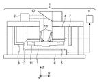
以下、添付図面を参照しながら本発明の実施形態を説明する。図1はインプリント装置の一例を示す。本実施形態のインプリント装置は、基板上に塗布されたインプリント材(レジスト)と型により成形してパターンを形成するインプリント処理を基板の複数のショット領域のそれぞれに行う、光硬化法のインプリント装置である。以下の図において、型に対する紫外線の照射軸(後述の照明系2の光路折り曲げ後の光軸)に平行にZ軸を取り、Z軸に垂直であって且つ互いに垂直な2つの方向にそれぞれX軸・Y軸を取って説明する。 Hereinafter, embodiments of the present invention will be described with reference to the accompanying drawings. FIG. 1 shows an example of an imprint apparatus. The imprint apparatus according to the present embodiment is a photo-curing method that performs imprint processing for forming a pattern by forming an imprint material (resist) applied on a substrate and a mold on each of a plurality of shot regions of the substrate. It is an imprint apparatus. In the following figures, the Z axis is taken in parallel with the irradiation axis of the ultraviolet rays on the mold (the optical axis after bending the optical path of the illumination system 2 described later), and each of the X directions is perpendicular to the Z axis and perpendicular to each other. A description will be given taking the axis and the Y axis.
インプリント装置1は、照明系2、型3を吸着力や静電力により引き付けて保持する型保持部4、基板5を保持する基板ステージ(基板保持部)6、塗布部7、型搬送機構8及び制御器9を備える。基板ステージ6は、基板の表面と平行な方向(第1方向)に位置決め可能である。照明系2は、インプリント処理の際に型3に対して紫外線10を照明する。照明系2は、光源と、該光源から射出された紫外線をインプリント処理に適切な光に調整するための複数の光学素子とを含む。型3は、基板5に対向するパターン面に所定のパターンが3次元状に形成されている。
The imprint apparatus 1 includes an illumination system 2, a
インプリント装置は、型3に力を加えることにより、型3に形成されたパターン面の少なくともX軸方向における寸法を補正する補正機構11と、スコープ13とを含む。スコープ13は、基板5に形成された基板マークと型3に形成された型マークとを型3を介して検出することによって基板5と型3との位置ずれ量を計測するTTM(Through The Mask)スコープであり、位置ずれ計測器を構成している。スコープ13により、基板5と型3とのX方向及びY方向における位置ずれ量を計測することができる。型保持部4は、基板5上に塗布されたレジスト18に型3を押し付ける押印動作を行うために、Z軸方向に駆動される。レジスト18を硬化後、型保持部4をZ軸方向に駆動することによって、基板5から型3を引き剥がす離型動作が行われる。押印動作及び離型動作は、型保持部4をZ方向に駆動して実現してもよいが、基板ステージ6をZ方向に駆動することで実現してもよい。型保持部4及び基板ステージ6の少なくとも一方を、型3とレジスト18とが互いに接触するように、駆動軸に沿って駆動する駆動機構を第1駆動機構と称する。型保持部4はその駆動機構を併せてインプリントヘッドとも称される。
The imprint apparatus includes a
基板ステージ6は、基板5を真空吸着により保持し、かつ、X方向、Y方向に位置決め可能である。基板ステージ6の駆動部は、ショット領域が型3に対して位置決めされるように基板ステージ6をX方向、Y方向に移動させる第2駆動機構を構成する。しかし、第2駆動機構は、基板ステージ6及び型保持部4の少なくとも一方を移動させればよい。塗布部7は、基板5上に未硬化のレジスト(インプリント材)18を塗布する。レジスト18は、照明系2からの紫外線10を受光することにより硬化する光硬化樹脂である。型搬送機構8は、型3を搬送し、型3を型保持部4に対して設置する。
The
制御器9は、インプリント装置1の各ユニットの動作を制御し、干渉計15,16の値などの取得を行う。制御器9は、インプリント装置1の各ユニットに回線により接続された、記憶部を有する不図示のコンピュータ又はシーケンサなどで構成される。本実施形態では、制御器9は、スコープ13により計測された基板5と型3との位置ずれ量を基にアライメント補正値を決定し、補正機構11及び基板ステージ6を制御して、アライメント補正を行う。制御器9はインプリント装置1内に構成してもよいし、もしくは、インプリント装置1とは別の場所に設置し、遠隔で制御する構成としても良い。
The controller 9 controls the operation of each unit of the imprint apparatus 1 and acquires the values of the
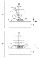
図2に、インプリント処理における型3及び基板5に着目した概念図を示す。基板ステージ6に基板5が搭載されると、スコープ13によるアライメント計測により、基板5上のショット領域の配列が計測される。アライメント方式は、グローバルアライメント方式とダイバイダイアライメント方式とに分類される。それぞれの詳細は、第1および第2実施形態に記す。スコープ13は、型3のパターン面と基板5上のレジスト18とを数十μm程度の間隔を開けて接触させない状態で型マークと基板マークとを計測する。この計測から、型3と基板5上のショット領域との位置ずれ量が計測される。このときのスコープの光軸を22として図示している。これは、型マークと基板マークとがともに矢印で示される光軸22上にあるときに、2つのマークが重なって見えるということを表している。通常、複数のスコープ13によって型マークおよび基板マークの複数対をそれぞれ検出することで、型3とショット領域との間のX方向、Y方向におけるシフトずれ、回転ずれ、さらには、倍率ずれなども計測する。ここでは便宜上、スコープ13によってX方向の位置ずれのみを計測するものとして説明する。
FIG. 2 shows a conceptual diagram focusing on the
インプリントヘッドは、通常、Z方向の駆動軸を持つ。基板ステージ6が目標位置に達すると、インプリントヘッドがZ方向に駆動し、型3をレジスト18に押し付ける。このインプリントを行った状態が、図2に状態2Cとして示される。スコープ13による計測によって、基板5上のショット領域と型3とが事前に位置合わせされているので、良好なオーバーレイ精度を得ることができる。
The imprint head usually has a drive shaft in the Z direction. When the
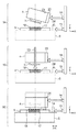
ここで、図3のように、スコープの光軸22が、インプリントヘッドの駆動軸に対して傾きを持っている場合を考える。図3の状態3Aでも、スコープ13によって、型マークと基板マークが位置合わせされていると計測される。ただし、この状態3Aは、あくまでスコープ13の光軸が傾いているためにそのように計測されてしまうものであり、実際には、基板5上のショット領域の中心と型3の中心との間には位置ずれ23が生じている。その結果、状態3Bのように、実際にインプリント処理を行うと、基板5上のショット領域とずれた位置にインプリントしてしまうことになる。これが、オーバーレイ精度の低下の原因となる。
Here, consider a case where the
なお、状態3Aでは、あくまで便宜上、スコープ13の光軸22が、Z軸に対して傾いていると仮定し、インプリントヘッドの駆動軸はZ軸と平行であると仮定した。スコープ13の光軸22がZ軸と平行であり、インプリントヘッドの駆動軸がZ軸に対して傾いている場合でも、まったく同様である。実際には、両者ともZ軸に対して少なからず傾きを持っている。オーバーレイ精度の低下の要因となるものは、あくまで、インプリントヘッドの駆動軸に対するスコープ13の光軸22の傾きであることに注意が必要である。
In the
そこで、良好なオーバーレイ精度を得るために、まず、実際に生産用の基板5を装置に投入する前や装置調整時やメンテナンス時に、インプリントヘッドの駆動軸に対するスコープ13の光軸22の傾きを求める。これを、図4を用いて説明する。基板ステージ6は、基板マークが形成された基板5を搭載している。また、インプリントヘッドは、型マークが形成された型3を搭載している。この状態で、基板マークと型マークとが重なるように、基板ステージ6を駆動させる。スコープ13によって基板マークと型マークとが重なって観察されるときのインプリントヘッドのZ位置をZ0とする。インプリントヘッドのZ位置がZ0であるときのスコープ13により計測された型マークと基板マークとの位置ずれ量は、0もしくは0付近である。
Therefore, in order to obtain good overlay accuracy, first, the inclination of the
この状態から、インプリントヘッドをZ方向に駆動する。駆動範囲は、スコープ13が計測可能な範囲で十分である。通常、プロキシミティ計測をするためのスコープ13は、NAがある程度低く、ある程度の焦点深度を持っている。この計測可能な範囲でインプリントヘッドをZ方向に駆動しながら、スコープ13により型マーク及び基板マークの計測を行う。インプリントヘッドのZ方向における位置とスコープ13による計測値との関係を、図5に示す。図5では、図4との関係が判り易いように、あえてZ軸を縦軸に配置している。また、Z値の+方向(紙面上方向)は、インプリントヘッドの移動方向が上方向、すなわち、型3と基板5が離れる方向である。Z0は、通常のスコープ13による計測時のインプリントヘッドのZ方向の位置とすると考えやすい。図4においても、最初の計測位置をZ0としている。
From this state, the imprint head is driven in the Z direction. As the drive range, a range that can be measured by the
ZUは、スコープ13による計測可能な範囲の、インプリントヘッドの最も上の位置(Z値が+方向)である。ZLは、型3と基板5の間隔を最も狭くしたとき、すなわち、型3と基板5が接触しない範囲でインプリントヘッドのZ位置を下(Z値を−方向)に駆動したときの位置である。この範囲内で、インプリントヘッドのZ位置を駆動し、スコープ13の計測を複数回実施する。こうして得られた図5のグラフ5Aにおいて、傾きCは、インプリントヘッドの駆動軸に対するスコープ13の光軸の傾きを示すことになる。
ZU is the uppermost position (Z value is in the + direction) of the imprint head within the range measurable by the
基板マークの代わりに基板ステージ6に搭載された基準マークを使用してもよい。これ以降の説明でも、便宜上、基板マークを計測することを前提に説明するが、これに限定するものではない。また、インプリントヘッドのZ位置がZ0のときのスコープ13の計測値を0近傍としたが、もちろん、これは必須の条件ではなく、ある値をもった状態から計測を開始してもよい。ただし、あまり計測値が大きい状態から始めると、インプリントヘッドをZ方向に駆動したときに、スコープ13の計測可能な範囲を超えてしまう場合や、計測値の信頼性が低下するなどの影響が考えられるため、計測値は0近傍がから開始するのが望ましい。さらに、傾きCは1次の傾きとしているが、もちろん、1次に限らず、高次関数や補正テーブルなどを用いてもよい。
A reference mark mounted on the
次に、傾きCからインプリント処理がなされたときに予想されるX方向における位置ずれ量ΔXを算出する。通常、傾きCはインプリントヘッドのZ位置に対して1次関数の傾きとなる。この場合、インプリントヘッドの各Z位置における型マークと基板マークとのX方向における位置ずれ量は、以下の式1で与えられる。ここで、ΔX(Z)は、インプリントヘッドのZ位置における型3と基板5のX方向における位置ずれ量の予測値である。ΔX(Z0)は、インプリントヘッドのZ位置がZ0のときのスコープ13の計測値である。Zは、インプリントヘッドの現在のZ位置であり、Z0は、スコープ13による計測時のインプリントヘッドのZ位置である。
ΔX(Z)=ΔX(Z0)+C×(Z−Z0)・・・(1)
Next, a positional deviation amount ΔX in the X direction expected when imprint processing is performed from the inclination C is calculated. Usually, the slope C is a slope of a linear function with respect to the Z position of the imprint head. In this case, the amount of positional deviation in the X direction between the mold mark and the substrate mark at each Z position of the imprint head is given by the following equation (1). Here, ΔX (Z) is a predicted value of the amount of positional deviation in the X direction between the
ΔX (Z) = ΔX (Z0) + C × (Z−Z0) (1)
インプリント時すなわち型3と基板5が接触するときのインプリントヘッドのZ位置がZIであるとすると、インプリント時に型3と基板5上のショット領域との位置ずれ量は、式2のようになる。ここで、ΔXiは、インプリント時の型3と基板5上のショット領域とのX方向における位置ずれ量であり、ZIは、インプリント時のインプリントヘッドのZ位置である。
ΔXi=ΔX(ZI)=ΔX(Z0)+C×(ZI−Z0)・・・(2)
Assuming that the Z position of the imprint head at the time of imprinting, that is, when the
ΔXi = ΔX (ZI) = ΔX (Z0) + C × (ZI−Z0) (2)
式1に従い、型3と基板5のX方向における位置ずれ量を予め予測し、その位置ずれ量だけ基板ステージ6を駆動して補正すればよい。つまり、スコープ13によって型3と基板5の位置ずれ量ΔX(Z0)が計測された後は、インプリントヘッドのZ位置の駆動に従って、ΔX(Z)を補正するように基板ステージ6をX方向に駆動する。この補正のための駆動は、できるだけリアルタイムに行うのが望ましい。インプリントヘッドのZ位置がインプリント位置ZIに達するときには、基板ステージ6の駆動量がΔXiになっているため、型3と基板5上のショット領域の位置がずれることなく、正しい位置にインプリントを行うことが可能である。
According to Equation 1, the amount of positional deviation in the X direction between the
Z0とZIが常に一定であるなら、ΔX(Z0)とΔX(ZI)の関係も常に一定であるため、基板ステージ6の補正のための駆動量も一定としてもかまわない。しかし、式2を用いれば、例えば図9のように基板5の表面に凹凸がありインプリント時のインプリントヘッドのZ位置がZIと異なった場合でも、正しい補正量ΔXを得ることが可能となり、より高精度のオーバーレイ精度を得ることが可能となる。図9の例では、基板5の表面の凹凸の影響により、あるショット領域Aでは、インプリント時のインプリントヘッドのZ位置がZIaである。また、あるショット領域Bではインプリント時のインプリントヘッドのZ位置がZIbである。このときの基板ステージ6のX方向の補正のための駆動量ΔXia,ΔXibは、下記の式2a、式2bで表される。
ΔXia=ΔX(ZIa)=ΔX(Z0a)+C×(ZIa−Z0)・・・(2a)
ΔXib=ΔX(ZIb)=ΔX(Z0b)+C×(ZIb−Z0)・・・(2b)
If Z0 and ZI are always constant, the relationship between ΔX (Z0) and ΔX (ZI) is also always constant, so the driving amount for correcting the
ΔXia = ΔX (ZIa) = ΔX (Z0a) + C × (ZIa−Z0) (2a)
ΔXib = ΔX (ZIb) = ΔX (Z0b) + C × (ZIb−Z0) (2b)
このように、式2を用いることで、基板5上の凹凸の影響を受けることなく、良好なオーバーレイ精度を得ることが可能である。ここで、ΔX(Z0a)及びΔX(Z0b)は、インプリント前に事前にスコープ13で計測した型3とショット領域A、BとのX方向における位置ずれ量である。図9の例では、ΔX(Z0a)及びΔX(Z0b)は、0近傍の値となる。また、詳細の説明は割愛するが、型3を交換することによって発生する型3の厚みの差による影響も、式1を用いることで問題なく補正することが可能である。なお、理解の助けのため、図5のグラフ5AのZ0とグラフ5BのZ0は同じであるとしたが、異なる位置でもまったく問題はない。
Thus, by using Formula 2, it is possible to obtain good overlay accuracy without being affected by unevenness on the
ここまでの説明は、インプリント時にインプリントヘッドをZ方向に駆動する方式についての説明である。しかし、インプリント時にインプリントヘッドではなく基板ステージ6をZ方向に駆動する方式も考えられる。その場合、図5のグラフ5AにおけるZ軸は、基板ステージ6のZ位置となり、傾きCは、基板ステージ6の駆動軸に対するスコープ13の光軸の傾きを表すことになる。そして、基板ステージ6のZ位置に応じて、基板ステージ6をX方向において補正駆動してやればよい。さらに、インプリントヘッドと基板ステージ6の両方をZ駆動してインプリントを行うこともできる。この場合、インプリントヘッドの駆動軸に対するスコープ13の光軸の傾きC1と、基板ステージ6の駆動軸に対するスコープ13の光軸の傾きC2との2つのパラメータを持てばよい。そして、インプリントヘッドのZ位置に依存する補正量と基板ステージ6のZ位置に依存する補正量の合算値で、基板ステージ6の位置を補正すればよい。
The description so far has been about the method of driving the imprint head in the Z direction during imprinting. However, a method of driving not the imprint head but the
図5のグラフ5Aにおいて、ZUとZLはある程度離れている方が、傾きCを精度よく算出するうえで望ましい。しかし、型3と基板5との間隔を十分小さくできない場合、つまりZLを十分に下位置にできない場合や、スコープ13の焦点深度が浅い場合などでは、ZUとZLを十分に離れた状態とすることができない。このような場合、まず通常通りに、インプリントヘッドのZ位置がZ0である位置においてスコープ13による計測を行う。その状態でインプリント処理を行う。そして、インプリントされたパターンと基板5上の下地のショット領域との重なり状態を外部の計測器を用いるなどして計測する。このときの位置ずれ量をΔXiとする。すると、傾きCは、以下の式3のように算出することが可能である。ここで、ΔXiは、インプリントされたパターンと基板5上のショット領域のX方向における位置ずれ量である。ZIは、インプリント処理がなされたときのインプリントヘッドのZ位置であり、Z0は、スコープ13による計測がなされたときのインプリントヘッドのZ位置である。(ZI−Z0)は、前記計測及び前記インプリント処理がそれぞれなされたときのインプリントヘッドと基板5との間の鉛直方向における間隔である。
C=ΔXi/(ZI−Z0)・・・(3)
このときのグラフは、図5のグラフ5Cのようになる。計測点が2点のみなので、複数のショット領域の平均値を用いるなどして、計測精度を向上させる必要がある。
In the
C = ΔXi / (ZI−Z0) (3)
The graph at this time is like a graph 5C in FIG. Since there are only two measurement points, it is necessary to improve measurement accuracy by using an average value of a plurality of shot areas.
これまでの説明では、インプリントヘッドのZ駆動の方向は、メカニカルに決まっている前提で記述してきた。しかし、実際には、メカニカルにナノメートルのオーダーで安定させることは困難である。とくに、グローバルアライメント方式においては、インプリントヘッドのZ駆動の方向がふらついていると、そのままオーバーレイ精度の低下につながる。そこで、図2の2Bに示されるように、インプリントヘッドにX方向、Y方向や回転方向の位置ずれを計測する干渉計16を配置することも考えられる。干渉計16によって、インプリントヘッドのX方向、Y方向、回転方向の位置を計測する。干渉計は、インプリントヘッドの側面の計測対象面に対してX方向に光を出射し、計測対象面で反射された光を受光することによってインプリントヘッドの基板ステージ6に対するX方向における相対位置を計測するセンサを構成している。干渉計のかわりにエンコーダを使用することもできる。図2の2Bでは、簡略化してX方向の干渉計16のみを図示している。基板ステージ6の位置を計測する干渉計15は、干渉計16と同じ基準から計測するのが望ましい。干渉計16の計測対象面25は、インプリントヘッドに搭載されている。同様に、干渉計15の計測対象24は、基板ステージ6に搭載されている。計測対象24、25は、反射ミラーが用いられる。つまり、インプリントヘッドのX方向、Y方向、回転方向の位置を、メカニカルに保証するのではなく、変動してしまった量を正確に計測し、その変動分を基板ステージ6を駆動することで補正するという考え方である。このような構成の場合、インプリントヘッドのZ駆動の方向は、メカニカルに決められた方向ではなく、インプリントヘッドに取り付けられた干渉計16が計測する対象面25の傾斜に依存することになる。干渉計15,16は、型保持部4、基板ステージ6の位置をそれらの側面を介して計測する位置計測器を構成している。
In the description so far, the Z drive direction of the imprint head has been described on the assumption that it is mechanically determined. However, in practice, it is difficult to mechanically stabilize on the nanometer order. In particular, in the global alignment method, if the Z drive direction of the imprint head fluctuates, the overlay accuracy is reduced as it is. Therefore, as shown in 2B of FIG. 2, it is conceivable to arrange an
この現象について図6を用いて説明する。スコープ13の光軸22は、Z軸に対して真っ直ぐであったと仮定する。また、インプリントヘッドの駆動軸も、Z軸の方向であったと仮定する。インプリントヘッドのX方向の位置を計測する干渉計16が計測する対象面25が、Z軸に対してある傾きを持っているとする。この状態で、インプリント処理を実施するためにインプリントヘッドがZ駆動を行う。すると、干渉計16の計測値は、対象面25の傾きとインプリントヘッドのZ駆動量の積に相当する値だけの誤差ΔXiを含むことになる。この誤差ΔXiは、インプリント装置の制御器9によって、基板ステージ制御系に送られ、ΔXiだけ基板ステージ6の補正駆動を行う。基板ステージ6の補正駆動は、本来、オーバーレイ精度の低下を防ぐための補正駆動であるが、インプリントヘッドのX方向の位置を計測する干渉計16の誤差分ΔXiに関しては、オーバーレイを損なう方向に働いてしまう。インプリントヘッドの駆動軸が、Z軸に対して傾きを持っていた場合、このX方向のずれ量は、インプリントヘッドのX方向の位置を計測する干渉計16で正しく計測される。したがって、インプリントヘッドの駆動軸の傾きに起因するX方向の位置ずれ分は正しく基板ステージ6の補正駆動に反映させることが可能である。干渉計16によってインプリントヘッドのX方向の位置を計測する構成においては、インプリントヘッドの駆動方向そのものは問題にならず、干渉計16が計測する対象面25の傾きに起因する位置ずれが、X方向における位置ずれのすべてになる。よって、この場合、傾きCは、干渉計16が計測する対象面25に対するスコープ13の光軸22の傾きを表すことになる。基板ステージ6は、干渉計16の値によって補正駆動が行われるため、干渉計16の値を補正してやればよいことになる。
This phenomenon will be described with reference to FIG. Assume that the
ここで気を付けなければならいのは、インプリントヘッドを傾斜させた成分も、干渉計16が計測する対象面25を傾斜させてしまうことである。図7の状態7Aは、スコープ13の光軸22、インプリントヘッドの駆動軸、干渉計16が計測する対象面25のすべてが、Z軸に対して平行である状態とする。すなわち、傾きCが0の状態であり、基板ステージ6を補正駆動しなくも、精度よくインプリントができる理想的な状態である。この状態7Aのインプリントヘッドにある型3を搭載するのであるが、この型3の表面が基板5の表面に対して傾斜した状態でインプリントヘッドに装着された場合を考える。このままインプリントヘッドをZ駆動してインプリント処理を行うと、型3の端面から基板5に接してしまう。そのため、型3の傾斜を是正するためにインプリントヘッドを傾斜させる必要がある。よって、型3の表面を計測する不図示の干渉計などを用いて型3の表面の傾斜を計測後、インプリントヘッドを傾斜させることで、型3の表面と基板5の表面を平行にする(状態7B)。この状態Bで、スコープ13によって型マーク及び基板マークの計測を行い、型3と基板5上のショット領域の位置が一致していることを確認する。その上で、インプリントヘッドをZ駆動し、インプリント処理を行う(状態7C)。インプリントヘッドのX位置を計測するための干渉計16が計測する対象面25は、インプリントヘッドの傾斜に伴い、傾斜成分をもってしまう。この状態でインプリントヘッドをZ駆動すると、干渉計16は、図6の状態6Bと同様に、ΔXiだけX方向の誤差を持つこととなる。すると、やはり状態6Bと同様に、基板ステージ6が間違った補正駆動を行ってしまうため、インプリントされたパターンは、基板5上のショット領域の位置とΔXiだけずれてしまうことになる。
Here, it should be noted that the component that tilts the imprint head also tilts the
図6のように、干渉計16が計測する対象面25が最初から傾斜成分をもっている場合は、この傾斜成分を計測することが可能であり、制御器9によって、その傾斜成分による位置ずれを補正し、より正確なオーバーレイを達成することができる。しかし、図7のようにインプリントヘッドの傾斜成分は、傾きCを求めた後に発生する成分である。よって、傾きCとは別に、この傾斜量を組み込む必要がある。このインプリントヘッドの傾斜成分を含んだ式が、以下の式4である。ここで、CIはインプリントヘッドの傾斜量である。
ΔX(Z)=ΔX(Z0)+(C+CI)×(Z−Z0)・・・(4)
以上のように、インプリントヘッドの傾斜量も加味して、インプリントヘッドのZ駆動に伴う誤差を補正することが可能で、良好なオーバーレイを実現することができる。
As shown in FIG. 6, when the
ΔX (Z) = ΔX (Z0) + (C + CI) × (Z−Z0) (4)
As described above, in consideration of the inclination amount of the imprint head, it is possible to correct an error accompanying the Z drive of the imprint head, and it is possible to realize a good overlay.
つづいて、本発明の実施のタイミングに関して述べる。型3と基板5との位置ずれの補正は、通常のインプリント時には常に行う。インプリントヘッド又は基板ステージ6の駆動軸に対するスコープ13の光軸22の傾きCの取得は、通常は、インプリント装置を起動若しくは再起動したときに行えばよい。その場合、取得された傾きCの値が変動しないことが前提となる。すなわち、スコープ13の光軸の傾きとインプリントヘッドのZ駆動方向の傾きがどちらも安定している必要がある。ところが、そのようなメカニカルな状態は、時間経過によって変動してしまう可能性が高い。また、装置状態に依存して変動してしまうこともある。傾きCが時間経過によって変動する場合、定期的に傾きCを取得し直す必要がある。傾きCが装置状態によって変動してしまう場合、装置状態が変動したときに、傾きCを取得し直す。
Next, the implementation timing of the present invention will be described. Correction of misalignment between the
スコープ13は、通常、ショット領域の基板マークの位置に応じてXY方向に移動できるように駆動軸を持たせている。つまり、サイズの異なるショット領域のインプリント処理を行う場合など、基板マークの位置も異なることになるので、それに合わせてスコープ13の位置をXY方向に駆動し、基板マークがスコープ13の視野に入るようにする。また、ダイバイダイアライメント方式において、基板5の周辺に存在するショット領域のように一部が欠けたショット領域にインプリント処理を行う場合、欠けのないショット領域で使用されていた基板マークが存在しない場合がある。このような場合、ショット領域内の別の基板マークを使用することになる。このときも、新たに使用したい基板マークの位置にスコープ13を移動させる必要がある。このようにスコープ13の移動が実施されると、スコープ13の光軸の傾きが、移動前後で変動する可能性がある。そこで、スコープ13を移動させたときに、傾きCを計測し直すこともできる。
The
同様に、装置の電源を入れる、あるいは、リセットを行った場合など、インプリントヘッドの原点出しを行った場合には、インプリントヘッドの駆動軸の傾きが変動する可能性が高い。ここでは考えやすいように、インプリントヘッドのXY位置を計測する干渉計がある場合を考える。装置の電源を入れた直後、インプリントヘッドの原点出しを行うが、そのとき、図8の状態8Aのように、インプリントヘッドが傾斜をもった状態をインプリントヘッドの傾斜の原点としてしまった場合を考える。この場合、図7の状態7A、7Bと同様に、型3の表面を基板5の表面と平行にするため、インプリントヘッドの傾斜駆動を行う。インプリントヘッドの傾斜駆動を行う駆動機構は、第3駆動機構を構成する。インプリントヘッドの傾斜駆動を行った後の状態8Bでインプリントするが、仮に、スコープ13の光軸及び干渉計16が計測する対象面25がZ軸に対して平行であれば、オーバーレイ精度の低下はないように見えてしまう。しかし、式4を用いている場合、図8の8Cに示されるように、基板ステージ6がインプリントヘッドを傾斜させた量に対応する分だけ余計な補正駆動を行ってしまい、正確なオーバーレイが達成できなくなってしまう。これは、式4において、型3と基板5上のショット領域の位置が合っているのでΔX(Z0)=0、C=0、インプリント時のZ位置Z=ZIを代入することになり、式4は式5に変形され、ΔXiだけ、誤差が生じることになる。
ΔXi=ΔX(ZI)=CI×(ZI−Z0)・・・(5)
Similarly, when the origin of the imprint head is determined such as when the apparatus is turned on or reset, the inclination of the drive shaft of the imprint head is likely to fluctuate. Here, for easy understanding, consider a case where there is an interferometer that measures the XY position of the imprint head. Immediately after turning on the power of the apparatus, the origin of the imprint head is determined. At that time, as shown in the state 8A of FIG. Think about the case. In this case, as in the
ΔXi = ΔX (ZI) = CI × (ZI−Z0) (5)
図8の8Cでは、一見、CIも0のように見えるが、インプリントヘッドの傾斜角CIは、インプリントヘッドの傾斜の原点(初期の傾斜角)からの傾斜量(傾斜角)である。したがって、図8の状態8Aのようにインプリントヘッドの傾斜の原点がずれている場合、図8の8Cで、CIはある値を持つことになる。そのため、ΔXiが0にならず、基板ステージ6が余計な補正駆動を行ってしまう。
In FIG. 8C, CI appears to be 0 at first glance, but the tilt angle CI of the imprint head is the tilt amount (slope angle) from the origin (initial tilt angle) of the tilt of the imprint head. Therefore, when the origin of the tilt of the imprint head is shifted as in the state 8A in FIG. 8, the CI has a certain value at 8C in FIG. Therefore, ΔXi does not become 0, and the
そこで、式4をインプリントヘッドの傾斜の原点を加味した式に直すと、式6のようになる。ここで、C0はインプリントヘッドの原点出し後の傾斜量、CIはインプリントヘッドの原点を基準とした駆動量である。
ΔX(Z)=ΔX(Z0)+(C+{CI−C0})×(Z−Z0)・・・(6)
Therefore, when
ΔX (Z) = ΔX (Z0) + (C + {CI−C0}) × (Z−Z0) (6)
したがって、インプリントヘッドの傾斜の原点C0を取得する必要がある。その対策の一つが、傾きCの算出をやり直すことである。すなわち、あたらしい傾きC’が計測されることで、式4は、以下の式6のようになる。
ΔX(Z)=ΔX(Z0)+(C’+CI)×(Z−Z0)
ここで、C’=C−C0 ・・・(7)
Therefore, it is necessary to obtain the origin C0 of the inclination of the imprint head. One countermeasure is to redo the calculation of the slope C. In other words, by measuring the new slope C ′,
ΔX (Z) = ΔX (Z0) + (C ′ + CI) × (Z−Z0)
Here, C ′ = C−C0 (7)
すなわち、新しい傾きC’は、インプリントヘッドの傾斜の原点のずれを含んだ値となる。新しい傾きC’が求まれば、傾きCは既知であるため、C0、つまり、インプリントヘッドの傾斜の原点のずれが分かることになる。つまり、装置の起動時やリセット時など、インプリントヘッドの傾斜の原点が変動してしまうようなタイミングでインプリントヘッドの原点出しを行った時に、新しい傾きC’を算出することで、良好なオーバーレイ精度を得ることができる。 That is, the new inclination C ′ is a value including the deviation of the origin of the imprint head inclination. If the new inclination C ′ is obtained, since the inclination C is known, C0, that is, the deviation of the origin of the inclination of the imprint head can be known. In other words, when the origin of the imprint head is determined at a timing at which the origin of the imprint head tilt fluctuates, such as when the apparatus is started or reset, it is possible to obtain a good result by calculating the new tilt C ′. Overlay accuracy can be obtained.
なお、基板マークが形成された基板を用いると説明したが、頻繁に傾きCの算出を行う場合には、基板ステージ6上に予めスコープ13計測用のマークを配置しておくことが望ましい。なお、インプリントヘッドの傾斜の概念を理解しやすいように、図2の2Bに示されるような干渉計16がある構成について説明した。しかし、干渉計16がない状態でも、まったく同様に扱うことができる。
In addition, although it demonstrated that the board | substrate with which the board | substrate mark was formed was used, when calculating inclination C frequently, it is desirable to arrange | position the mark for
以上、インプリントヘッドのZ駆動におけるX方向の位置ずれ補正に関する説明を行った。Y方向の補正に関しても同様である。また、スコープ13を複数含ませて、型3と基板5上のショット領域との間の形状の相違や回転を補正する場合、それらは、複数のマークのX方向の位置ずれ・Y方向の位置ずれから求まる量である。ショット領域の形状は、基板ステージ6の移動では補正できないため、図1に示されるパターン面の寸法を補正する補正機構11を用いる。これを、図10を用いて説明する。X方向の位置を計測するスコープ13を2つ(第1スコープおよび第2スコープ)用意することで、ショット領域のX方向の倍率も計測することが可能である。この2つのスコープ13の光軸22の傾きが同じであれば、インプリントヘッドのZ位置に依存したΔXの誤差として現れる。しかし、状態10Aのように、2つのスコープ13の傾きが異なる場合、補正機構11で型3のパターン面の寸法を小さくすることで、はじめて2つのスコープ13により型マークと基板マークが一致するように計測される。
In the foregoing, the description has been given regarding the positional deviation correction in the X direction in the Z drive of the imprint head. The same applies to the correction in the Y direction. When a plurality of
しかし、この状態のままでインプリントヘッドをZ駆動してインプリントすると、図10(B)のように基板5上のショット領域よりも、小さいパターンをインプリントしてしまうことになる。そこで、各スコープ13についてそれらの光軸の傾きを求め、全スコープ13の傾きに基づいて、インプリント時のXYずれや回転、倍率(ショット領域の形状)なども求め、補正する。状態10Aの場合、2つのスコープ13の光軸の傾きは異なっており、インプリントヘッドのZ位置に応じて、倍率ずれが発生する。そこで、式4と同様にして、インプリントヘッドのZ位置に応じて倍率を補正すればよい。すなわち、スコープ13が2つの場合、2つのスコープ13の光軸の傾きの平均値がXのずれ量の傾きとなり、両者の傾きの差が倍率の傾きとなるのである。他の成分もまったく同様であり、スコープ13の数を増やすことで、補正可能な型3の形状も増えることになる。例えば、型3の4隅にX方向、Y方向それぞれの型マークを用意することで、X方向、Y方向及び回転のずれ、さらに、ショット領域が平行四辺形や台形の形状を有している場合等へも対応可能となる。一般的には、X方向、Y方向及び回転のずれは、基板ステージ6の移動により、形状のずれは、補正機構11の駆動により補正する。しかし、X方向、Y方向のずれや回転方向のずれも、補正機構11を用いて型3の位置をずらしてもよいし、また、インプリントヘッド自体に、補正機構11以外に、X方向やY方向、回転方向の駆動機構があれば、それで補正を行ってもよい。以下に、インプリント装置によるインプリント処理における各アライメント方式について述べる。
However, if the imprint head is Z-driven in this state and imprinted, a pattern smaller than the shot area on the
〔第1実施形態〕
第1実施形態として、スコープ13を用いたグローバルアライメント方式の説明を行う。グローバルアライメント方式は、基板5上の複数のサンプルショット領域の位置を計測することで、基板5全体のショット領域の配列を算出し、このときの基準は、基板ステージ6の位置基準となる。そこで、基板ステージ6の位置計測には高精度が求められる。そのため、図2の2Bで示したような干渉計15を用いて基板ステージ6の位置を計測するのが一般的である。また、グローバルアライメント方式によって、サンプルショット領域を計測後に、インプリントヘッドの位置がXY方向にずれてしまうと、それによってオーバーレイが損なわれてしまう。そこで、干渉計16によって、インプリントヘッドのXY方向や回転方向の位置ずれを計測する方式が望ましい。干渉計16によって計測されたインプリントヘッドの位置情報は、制御器9に送られ、制御器9は、基板ステージ6の位置を補正することで、より正確なオーバーレイを実現する。
[First Embodiment]
As a first embodiment, a global alignment method using a
基板ステージ6に基板5が搭載されると、スコープ13によるグローバルアライメント計測により、基板5上のショット領域の配列が計測される。このとき、型3と基板5とは、数十um程度の間隔を開けて非接触の状態で計測される。これを、サンプルショット領域に対して行う。この情報を基に、基板5上のショット領域の配列を算出する。次に、実際にインプリントを行う場合は、先のショット領域の配列の情報から、インプリント対象のショット領域17の位置を算出し、対象のショット領域がインプリント位置へ来るように、基板ステージ6を移動させる。基板ステージ6が目標位置に達すると、インプリントヘッドがZ方向に駆動し、型3をレジスト18に押し付ける。このとき、レジスト18は、インプリント直前に塗布する方法と、予め基板5全体に塗布しておく方法とがある。型3をレジスト18に押し当てると、型3のパターンにレジスト18が充填されるのを待ち、光を照射して、レジスト18を硬化させる。この後、インプリントヘッドをZ上方向へ駆動し、型3と基板5を引きはがす。この一連の動作を、基板5上の全ショット領域に対して行う。このとき、インプリントを行った状態が、図2の2Cに示されている。
When the
通常、スコープ13の光軸22と、干渉計16が計測する対象面25との間には、図6の状態6Aに示されるように、傾きの差がある。状態6Aでは、便宜上、スコープ13の光軸22がZ軸に対して平行であり、干渉計16の計測対象面25がZ軸に対して傾いている様子を示している。この傾きがあると、正確なオーバーレイを妨げる要因となってしまう。そこで、両者の傾きの差を求め、補正する必要がある。グローバルアライメント方式においては、干渉計16の計測値を補正する。このとき、図7のように、型3の表面が傾いたり、基板5表面が傾いたりしている場合に、型3と基板5の表面を平行にするため、インプリントヘッドの傾斜駆動を行う場合がある。この時に、干渉計16の計測対象面25も傾くことになるため、干渉計16が誤差を持つことになる。そこで、このインプリントヘッドの傾斜量を含めて補正する必要がある。一般的なインプリント装置は、インプリントヘッドがZ駆動を行う機構であるが、基板ステージ6がZ駆動を行うことでインプリントを行う機構でもよい。通常、あるロットを装置で処理する場合、事前にロットを流して検査する工程がある。このため、ロットの事前検査時に、実際にインプリントを行い、そのときのオーバーレイ精度の検査結果の値を用いてインプリントヘッドの傾斜量を算出してもよい。すなわち、スコープ13でマークを計測した時のずれ量とインプリントした時のずれ量との差と、インプリントヘッドのZ方向の移動量とから、傾きCを求めることができる。また、グローバルアライメント計測時に、ショット領域内の複数点を計測することで、ショット領域の歪みを求めて補正することもできる。複数のスコープ13で複数のマークを計測する場合、インプリントヘッドのZ駆動における、インプリント位置のずれのみでなく、インプリントされるパターンの形状の補正を行うことができる。図10は、一例として、スコープ13を2つ使用した場合の、インプリント時の倍率誤差が発生する様子を示している。この倍率誤差も、本発明によって、精度よく補正することが可能である。
Normally, there is a difference in inclination between the
傾きCの取得は、装置調整時に行うものであるが、装置状態が変わってしまう可能性のある場合にも行うことが望ましい。つまり、ロットが変わった時に、型3や基板5上のマークの配置が変わると、スコープ13の位置もそのマーク配置に合わせて変える必要がある。また、インプリントヘッドの位置を計測する干渉計16の原点出しを行った場合に、スコープ13の光軸22と干渉計16の計測対象面25との間の傾きの関係が変わる可能性があるため、傾きCを算出し直すのが望ましい。
The acquisition of the inclination C is performed at the time of device adjustment, but it is also desirable to perform it when there is a possibility that the device state may change. That is, when the arrangement of the marks on the
〔第2実施形態〕
第1実施形態においては、グローバルアライメントを用いたインプリントについて述べた。本発明は、ダイバイダイアライメント方式を用いたインプリントに適用することが可能である。
[Second Embodiment]
In the first embodiment, the imprint using global alignment has been described. The present invention can be applied to imprinting using a die-by-die alignment method.
ダイバイダイアライメント方式の場合は、図2のように、インプリントの直前に、スコープ13によって、基板5上のショット領域と型3との間の位置合わせを行う方式が一般的である。スコープ13により、型3のマークと基板5上のショット領域のマークとが一致するように基板ステージ6を移動させる。その状態で、インプリントを行えば、ショット領域上に型3のパターンを重ね合わせることが可能である。この場合、インプリントヘッドのメカ的な位置ずれは、スコープ13によって計測可能であるため、グローバルアライメント方式のような干渉計16は必須ではない。
In the case of the die-by-die alignment method, as shown in FIG. 2, a method of performing alignment between the shot area on the
図3のように、スコープ13とインプリントヘッドのZ駆動の方向がそれぞれ傾きを持っている場合、スコープ13で位置合わせを行ってからインプリントを行っても、インプリントされたパターンは、基板5上のショット領域とずれてしまう。これが、正確なオーバーレイを妨げる要因となる。ショット領域内の形状を補正したい場合に、複数のスコープ13を用意し、それぞれについて傾きを求める。干渉計16は必須ではないが、もちろん、あった方が望ましい。その理由は、図3のようなインプリントヘッドのZ駆動の方向は、メカニカルな要因で決まるため、ある程度変動する可能性があるためである。図2の2Bのような構成であれば、インプリントヘッドのZ駆動の方向の影響は受けず、干渉計16の計測対象面25と、スコープ13の光軸との関係で傾きCが求まる。
As shown in FIG. 3, when the Z drive direction of the
ダイバイダイアライメント方式においては、基板5の周辺に位置する一部が欠けたショット領域においては、基板マークのうちのいくつかが使用できない可能性がある。その場合、スコープ13を駆動して、別の基板マークを計測する必要がある。このとき、スコープ13が駆動することによって、スコープ13の光軸22が変動してしまう可能性がある。そこで、傾きCを取得し直すことが望ましい。なお、基板5の周辺のショット領域の欠け方は一様ではないため、場合によっては、ショット領域毎にスコープ13を駆動する必要が生じる。そのたびに傾きCを取得し直すと時間がかかるため、基板5の周辺のショット領域は、欠けていないショット領域のインプリントが終わった最後に行うなどの対応が必要である。その他については、グローバルアライメント方式と同等であるため、詳細は割愛する。
In the die-by-die alignment method, there is a possibility that some of the substrate marks cannot be used in a shot region where a part of the periphery of the
以上述べたように、本実施形態のインプリント装置は、グローバルアライメント方式やダイバイダイアライメント方式にかかわらず、より正確なオーバーレイを達成して、生産性向上に寄与するものである。 As described above, the imprint apparatus according to this embodiment contributes to productivity improvement by achieving more accurate overlay regardless of the global alignment method or the die-by-die alignment method.
[物品の製造方法の実施形態]
物品としてのデバイス(半導体集積回路素子、液晶表示素子等)の製造方法は、上述したインプリント装置を用いて基板(ウエハ、ガラスプレート、フィルム状基板)5にパターンを転写(形成)する工程を含む。さらに、該製造方法は、パターンを転写された基板5をエッチングする工程を含みうる。なお、パターンドメディア(記録媒体)や光学素子などの他の物品を製造する場合には、該製造方法は、エッチングの代わりに、パターンを転写された基板5を加工する他の処理を含みうる。本実施形態の物品製造方法は、従来の方法に比べて、物品の性能・品質・生産性・生産コストの少なくとも一つにおいて有利である。以上、本発明の実施の形態を説明してきたが、本発明はこれらの実施の形態に限定されず、その要旨の範囲内において様々な変形及び変更が可能である。
[Embodiment of Method for Manufacturing Article]
A method of manufacturing a device (semiconductor integrated circuit element, liquid crystal display element, etc.) as an article includes a step of transferring (forming) a pattern onto a substrate (wafer, glass plate, film-like substrate) 5 using the above-described imprint apparatus. Including. Further, the manufacturing method may include a step of etching the
Claims (12)
前記型を保持する型保持部と、
前記基板を保持する基板保持部と、
前記型と前記インプリント材とが互いに接触するように前記型保持部及び前記基板保持部のうち少なくとも一方を駆動軸に沿って移動させる第1駆動機構と、
前記駆動軸に交差する方向において前記基板が前記型に対して位置決めされるように前記型保持部及び前記基板保持部のうち少なくとも一方を移動させる第2駆動機構と、
前記型と前記インプリント材とが互いに接触していない状態で前記型に形成された型マークと前記基板に形成された基板マークとを前記型を介して検出するスコープを含み、前記型マークと前記基板マークとの間の位置ずれ量を計測する位置ずれ量計測器と、
制御器と、
を備え、
前記制御器は、前記型マークと前記基板マークとの間の位置ずれ量と前記型保持部及び前記基板保持部のうち少なくとも一方の前記駆動軸に沿う移動量との間の関係の情報と、該移動量の情報と、前記位置ずれ量計測器により得られた前記位置ずれ量の情報とに基づいて、前記第2駆動機構を制御する、
ことを特徴とするインプリント装置。 An imprint apparatus for forming an imprint material on a substrate with a mold to form a pattern on the substrate,
A mold holding unit for holding the mold;
A substrate holder for holding the substrate;
A first drive mechanism that moves at least one of the mold holding part and the substrate holding part along a drive shaft so that the mold and the imprint material are in contact with each other;
A second drive mechanism that moves at least one of the mold holder and the substrate holder so that the substrate is positioned with respect to the mold in a direction intersecting the drive axis;
A scope for detecting, via the mold, a mold mark formed on the mold and a substrate mark formed on the substrate in a state where the mold and the imprint material are not in contact with each other; A misregistration measuring device for measuring a misregistration amount between the substrate mark;
A controller;
With
Wherein the controller, and information on the relationship between the positional deviation amount and the die holding unit and the amount of movement along at least one of the drive shaft of the substrate holder between the substrate mark and the type mark, Controlling the second drive mechanism based on the information on the amount of movement and the information on the amount of displacement obtained by the displacement amount measuring instrument;
An imprint apparatus characterized by that.
前記制御器は、前記関係の情報として、前記側面に対する前記スコープの光軸の傾きの情報を用いる、ことを特徴とする請求項1に記載のインプリント装置。 A position measuring device for measuring the position of the mold holding unit moved by the first driving mechanism and the second driving mechanism in the intersecting direction through a side surface of the mold holding unit ;
The imprint apparatus according to claim 1, wherein the controller uses information on an inclination of an optical axis of the scope with respect to the side surface as the information on the relationship.
前記制御器は、前記関係の情報として、前記側面に対する前記スコープの光軸の傾きの情報を用いる、ことを特徴とする請求項1に記載のインプリント装置。 The imprint apparatus according to claim 1, wherein the controller uses information on an inclination of an optical axis of the scope with respect to the side surface as the information on the relationship.
前記側面に対する前記スコープの光軸の傾きの情報は、前記第3駆動機構により前記型保持部を傾斜させた後の前記側面に対する前記スコープの光軸の傾きの情報である、
ことを特徴とする請求項3に記載のインプリント装置。 A third driving mechanism for tilting the mold holding portion such as the type of surface and the surface of the substrate are parallel to each other,
The information on the inclination of the optical axis of the scope with respect to the side surface is information on the inclination of the optical axis of the scope with respect to the side surface after the mold holding portion is inclined with the third drive mechanism.
The imprint apparatus according to claim 3.
前記側面に対する前記スコープの光軸の傾きの情報は、前記第3駆動機構により前記基板保持部を傾斜させた後の前記側面に対する前記スコープの光軸の傾きの情報である、 The information on the inclination of the optical axis of the scope with respect to the side surface is information on the inclination of the optical axis of the scope with respect to the side surface after the substrate holding portion is inclined with the third drive mechanism.
ことを特徴とする請求項4に記載のインプリント装置。The imprint apparatus according to claim 4.
前記制御器は、前記関係の情報と、該移動量の情報と、前記位置ずれ量計測器により得られた複数対の前記型マークおよび前記基板マークそれぞれの間の位置ずれ量の情報とに基づいて、前記補正機構を制御する、
ことを特徴とする請求項1乃至請求項9のうちいずれか1項に記載のインプリント装置。 A correction mechanism for correcting the dimensions of the mold;
The controller is based on the information on the relationship, the information on the amount of movement, and the information on the amount of misalignment between the plurality of pairs of the mold mark and the substrate mark obtained by the misalignment amount measuring device. Controlling the correction mechanism,
The imprint apparatus according to claim 1, wherein the imprint apparatus is any one of claims 1 to 9 .
前記工程で前記パターンを形成された前記基板を加工する工程と、
を含むことを特徴とする物品の製造方法。 A step of a pattern formed on a substrate using an imprint apparatus according to any one of claims 1 to 11,
Processing the substrate on which the pattern is formed in the step;
A method for producing an article comprising:
Priority Applications (4)
| Application Number | Priority Date | Filing Date | Title |
|---|---|---|---|
| JP2011157123A JP5864929B2 (en) | 2011-07-15 | 2011-07-15 | Imprint apparatus and article manufacturing method |
| TW101123501A TWI554378B (en) | 2011-07-15 | 2012-06-29 | Imprint apparatus and article manufacturing method |
| US13/541,899 US9810979B2 (en) | 2011-07-15 | 2012-07-05 | Imprint apparatus and article manufacturing method |
| KR1020120073634A KR101576118B1 (en) | 2011-07-15 | 2012-07-06 | Imprint apparatus and article manufacturing method |
Applications Claiming Priority (1)
| Application Number | Priority Date | Filing Date | Title |
|---|---|---|---|
| JP2011157123A JP5864929B2 (en) | 2011-07-15 | 2011-07-15 | Imprint apparatus and article manufacturing method |
Publications (3)
| Publication Number | Publication Date |
|---|---|
| JP2013026288A JP2013026288A (en) | 2013-02-04 |
| JP2013026288A5 JP2013026288A5 (en) | 2014-08-21 |
| JP5864929B2 true JP5864929B2 (en) | 2016-02-17 |
Family
ID=47518490
Family Applications (1)
| Application Number | Title | Priority Date | Filing Date |
|---|---|---|---|
| JP2011157123A Active JP5864929B2 (en) | 2011-07-15 | 2011-07-15 | Imprint apparatus and article manufacturing method |
Country Status (4)
| Country | Link |
|---|---|
| US (1) | US9810979B2 (en) |
| JP (1) | JP5864929B2 (en) |
| KR (1) | KR101576118B1 (en) |
| TW (1) | TWI554378B (en) |
Families Citing this family (14)
| Publication number | Priority date | Publication date | Assignee | Title |
|---|---|---|---|---|
| JP6333039B2 (en) * | 2013-05-16 | 2018-05-30 | キヤノン株式会社 | Imprint apparatus, device manufacturing method, and imprint method |
| JP6120678B2 (en) | 2013-05-27 | 2017-04-26 | キヤノン株式会社 | Imprint method, imprint apparatus and device manufacturing method |
| JP6271875B2 (en) * | 2013-06-18 | 2018-01-31 | キヤノン株式会社 | Imprint apparatus, imprint method, and article manufacturing method |
| JP6315904B2 (en) | 2013-06-28 | 2018-04-25 | キヤノン株式会社 | Imprint method, imprint apparatus, and device manufacturing method |
| JP2015170815A (en) * | 2014-03-10 | 2015-09-28 | キヤノン株式会社 | Imprint device, alignment method, and manufacturing method for article |
| JP6415120B2 (en) * | 2014-06-09 | 2018-10-31 | キヤノン株式会社 | Imprint apparatus and article manufacturing method |
| RU2701780C2 (en) | 2014-09-22 | 2019-10-01 | Конинклейке Филипс Н.В. | Transfer method, as well as device and computer program product for implementation thereof |
| JP6497938B2 (en) * | 2015-01-05 | 2019-04-10 | キヤノン株式会社 | Imprint apparatus, imprint method, and article manufacturing method. |
| US10248018B2 (en) * | 2015-03-30 | 2019-04-02 | Canon Kabushiki Kaisha | Imprint apparatus and method of manufacturing article |
| US10484971B2 (en) * | 2015-05-08 | 2019-11-19 | Lg Electronics Inc. | Method and device for transmitting/receiving data using transport block size defined for machine type communication terminal in wireless access system supporting machine type communication |
| JP6381721B2 (en) * | 2017-03-30 | 2018-08-29 | キヤノン株式会社 | Imprint method, imprint apparatus and device manufacturing method |
| US11175598B2 (en) | 2017-06-30 | 2021-11-16 | Canon Kabushiki Kaisha | Imprint apparatus and method of manufacturing article |
| JP6979845B2 (en) * | 2017-10-11 | 2021-12-15 | キヤノン株式会社 | Imprint device and article manufacturing method |
| JP6560736B2 (en) * | 2017-12-28 | 2019-08-14 | キヤノン株式会社 | Imprint apparatus, imprint method, and article manufacturing method |
Family Cites Families (36)
| Publication number | Priority date | Publication date | Assignee | Title |
|---|---|---|---|---|
| JPH04185941A (en) | 1990-11-20 | 1992-07-02 | Tochigi Fuji Ind Co Ltd | Differential device |
| US20060005657A1 (en) * | 2004-06-01 | 2006-01-12 | Molecular Imprints, Inc. | Method and system to control movement of a body for nano-scale manufacturing |
| US7027156B2 (en) * | 2002-08-01 | 2006-04-11 | Molecular Imprints, Inc. | Scatterometry alignment for imprint lithography |
| TW568349U (en) * | 2003-05-02 | 2003-12-21 | Ind Tech Res Inst | Parallelism adjusting device for nano-transferring |
| JP2005101201A (en) * | 2003-09-24 | 2005-04-14 | Canon Inc | Nano-imprint system |
| JP4574240B2 (en) * | 2004-06-11 | 2010-11-04 | キヤノン株式会社 | Processing apparatus, processing method, device manufacturing method |
| US7309225B2 (en) * | 2004-08-13 | 2007-12-18 | Molecular Imprints, Inc. | Moat system for an imprint lithography template |
| JP3958344B2 (en) * | 2005-06-07 | 2007-08-15 | キヤノン株式会社 | Imprint apparatus, imprint method, and chip manufacturing method |
| JP4290177B2 (en) * | 2005-06-08 | 2009-07-01 | キヤノン株式会社 | Mold, alignment method, pattern forming apparatus, pattern transfer apparatus, and chip manufacturing method |
| US7298495B2 (en) * | 2005-06-23 | 2007-11-20 | Lewis George C | System and method for positioning an object through use of a rotating laser metrology system |
| JP4533358B2 (en) * | 2005-10-18 | 2010-09-01 | キヤノン株式会社 | Imprint method, imprint apparatus and chip manufacturing method |
| JP2007173614A (en) * | 2005-12-22 | 2007-07-05 | Ricoh Co Ltd | Micro fabricating device |
| US7875866B2 (en) * | 2006-03-24 | 2011-01-25 | Pioneer Corporation | Beam recording apparatus and beam adjustment method |
| JP4185941B2 (en) * | 2006-04-04 | 2008-11-26 | キヤノン株式会社 | Nanoimprint method and nanoimprint apparatus |
| JP4795300B2 (en) * | 2006-04-18 | 2011-10-19 | キヤノン株式会社 | Alignment method, imprint method, alignment apparatus, imprint apparatus, and position measurement method |
| JP4958614B2 (en) * | 2006-04-18 | 2012-06-20 | キヤノン株式会社 | Pattern transfer apparatus, imprint apparatus, pattern transfer method, and alignment apparatus |
| JP4848832B2 (en) * | 2006-05-09 | 2011-12-28 | 凸版印刷株式会社 | Nanoimprint apparatus and nanoimprint method |
| JP5371349B2 (en) * | 2008-09-19 | 2013-12-18 | キヤノン株式会社 | Imprint apparatus and article manufacturing method |
| JP2010080631A (en) * | 2008-09-25 | 2010-04-08 | Canon Inc | Stamping device and method of manufacturing article |
| JP2010080630A (en) * | 2008-09-25 | 2010-04-08 | Canon Inc | Stamping device and method of manufacturing article |
| JP5361309B2 (en) | 2008-09-25 | 2013-12-04 | キヤノン株式会社 | Imprint apparatus and imprint method |
| NL2004281A (en) * | 2009-03-19 | 2010-09-20 | Asml Netherlands Bv | Lithographic apparatus and device manufacturing method. |
| JP2010283207A (en) * | 2009-06-05 | 2010-12-16 | Toshiba Corp | Pattern forming device and pattern forming method |
| NL2005092A (en) * | 2009-07-16 | 2011-01-18 | Asml Netherlands Bv | Object alignment measurement method and apparatus. |
| JP5662741B2 (en) * | 2009-09-30 | 2015-02-04 | キヤノン株式会社 | Imprint apparatus and article manufacturing method |
| JP2011124346A (en) * | 2009-12-09 | 2011-06-23 | Canon Inc | Imprint apparatus and article manufacturing method |
| JP5809409B2 (en) * | 2009-12-17 | 2015-11-10 | キヤノン株式会社 | Imprint apparatus and pattern transfer method |
| NL2006454A (en) * | 2010-05-03 | 2011-11-07 | Asml Netherlands Bv | Imprint lithography method and apparatus. |
| JP5539011B2 (en) * | 2010-05-14 | 2014-07-02 | キヤノン株式会社 | Imprint apparatus, detection apparatus, alignment apparatus, and article manufacturing method |
| JP5669466B2 (en) * | 2010-07-12 | 2015-02-12 | キヤノン株式会社 | Holding apparatus, imprint apparatus and article manufacturing method |
| WO2012016744A1 (en) * | 2010-08-05 | 2012-02-09 | Asml Netherlands B.V. | Imprint lithography |
| JP5395769B2 (en) * | 2010-09-13 | 2014-01-22 | 株式会社東芝 | Template chuck, imprint apparatus, and pattern forming method |
| JP6039222B2 (en) * | 2011-05-10 | 2016-12-07 | キヤノン株式会社 | Detection apparatus, detection method, imprint apparatus, and device manufacturing method |
| JP6066565B2 (en) * | 2012-01-31 | 2017-01-25 | キヤノン株式会社 | Imprint apparatus and article manufacturing method |
| JP6180131B2 (en) * | 2012-03-19 | 2017-08-16 | キヤノン株式会社 | Imprint apparatus and article manufacturing method using the same |
| JP5723337B2 (en) * | 2012-09-07 | 2015-05-27 | 株式会社東芝 | Pattern forming method and pattern forming apparatus |
-
2011
- 2011-07-15 JP JP2011157123A patent/JP5864929B2/en active Active
-
2012
- 2012-06-29 TW TW101123501A patent/TWI554378B/en active
- 2012-07-05 US US13/541,899 patent/US9810979B2/en active Active
- 2012-07-06 KR KR1020120073634A patent/KR101576118B1/en active IP Right Grant
Also Published As
| Publication number | Publication date |
|---|---|
| KR101576118B1 (en) | 2015-12-10 |
| TW201302419A (en) | 2013-01-16 |
| US9810979B2 (en) | 2017-11-07 |
| US20130015597A1 (en) | 2013-01-17 |
| TWI554378B (en) | 2016-10-21 |
| KR20130009630A (en) | 2013-01-23 |
| JP2013026288A (en) | 2013-02-04 |
Similar Documents
| Publication | Publication Date | Title |
|---|---|---|
| JP5864929B2 (en) | Imprint apparatus and article manufacturing method | |
| US11460768B2 (en) | Pattern formation method, lithography apparatus, lithography system, and article manufacturing method | |
| JP5809409B2 (en) | Imprint apparatus and pattern transfer method | |
| KR101965929B1 (en) | Imprint apparatus, imprint system, and method of manufacturing article | |
| JP6120678B2 (en) | Imprint method, imprint apparatus and device manufacturing method | |
| US8953175B2 (en) | Mark position detector, imprint apparatus, and article manufacturing method | |
| US8404169B2 (en) | Imprint apparatus and method of manufacturing article | |
| US9915868B2 (en) | Imprint apparatus, imprint method, and article manufacturing method | |
| US9910351B2 (en) | Imprint apparatus and article manufacturing method | |
| KR20110132238A (en) | Lithographic apparatus and manufacturing method of commodities | |
| KR20120038376A (en) | Imprint method and apparatus, and device manufacturing method | |
| US10241424B2 (en) | Imprint apparatus, imprint method, and article manufacturing method | |
| JP5930699B2 (en) | Imprint apparatus, imprint method, and device manufacturing method | |
| JP2017123493A (en) | Imprint method, imprint device, and device manufacturing method | |
| JP5687165B2 (en) | Proximity exposure apparatus, substrate positioning method for proximity exposure apparatus, and display panel substrate manufacturing method | |
| JP2019179926A (en) | Pattern formation method, lithographic apparatus, lithographic system, and article manufacturing method | |
| US10036967B2 (en) | Lithography apparatus, lithography method, and article manufacturing method | |
| JP2016021440A (en) | Imprint device, imprint method, and method of manufacturing article | |
| JP2014110384A (en) | Imprint device, imprint method, and device manufacturing method | |
| US20230182356A1 (en) | Imprint apparatus and article manufacturing method | |
| JP5166681B2 (en) | Step-type proximity exposure system |
Legal Events
| Date | Code | Title | Description |
|---|---|---|---|
| A521 | Written amendment |
Free format text: JAPANESE INTERMEDIATE CODE: A523 Effective date: 20140708 |
|
| A621 | Written request for application examination |
Free format text: JAPANESE INTERMEDIATE CODE: A621 Effective date: 20140708 |
|
| A977 | Report on retrieval |
Free format text: JAPANESE INTERMEDIATE CODE: A971007 Effective date: 20150410 |
|
| A131 | Notification of reasons for refusal |
Free format text: JAPANESE INTERMEDIATE CODE: A131 Effective date: 20150424 |
|
| A521 | Written amendment |
Free format text: JAPANESE INTERMEDIATE CODE: A523 Effective date: 20150623 |
|
| TRDD | Decision of grant or rejection written | ||
| A01 | Written decision to grant a patent or to grant a registration (utility model) |
Free format text: JAPANESE INTERMEDIATE CODE: A01 Effective date: 20151130 |
|
| A61 | First payment of annual fees (during grant procedure) |
Free format text: JAPANESE INTERMEDIATE CODE: A61 Effective date: 20151225 |
|
| R151 | Written notification of patent or utility model registration |
Ref document number: 5864929 Country of ref document: JP Free format text: JAPANESE INTERMEDIATE CODE: R151 |